

Page 1

Installation Guide for
the Model FE104 and
Model FE108 Fast
Ethernet Hubs
NETGEAR
4500 Great America Parkway
Santa Clara, CA 95054
USA
Phone: 1-888-NETGEAR
E-mail: support@NETGEAR.com
www.NETGEAR.com
M-FE100NA-1
September 2000
, Inc.
Page 2

© 2000 by NETGEAR, Inc. All rights reserved.
Trademarks
NETGEAR™ is a trademark of NETGEAR, Inc. Windows® is a registered trademark of Microsoft Corporation. Other
brand and product names are trademarks or registered trademarks of their respective holders. Information is subject to
change without notice. All rights reserved.
Statement of Conditions
In the interest of improving internal design, operational function, and/or reliability, NETGEAR reserves the right to
make changes to the products described in this document without notice.
NETGEAR does not assume any liability that may occur due to the use or application of the product(s) or circuit
layout(s) described herein.
Federal Communications Commission (FCC) Declaration of Conformity Statement
Note: This equipment has been tested and found to comply with the limits for a Class A digital device, pursuant to
Part 15 of the FCC rules. These limits are designed to provide reasonable protection against harmful interference when
the equipment is operated in a commercial environment. This equipment generates, uses, and can radiate radio frequenc y
energy. If it is not installed and used in accordance with the instruction manual, it may cause harmful interference to
radio communications. Operation of this equipment in a residential area is likely to cause harmful interference, in which
case users will be required to take whatever measures may be necessary to correct the interference at their own expense.
EN 55 022 Statement
This is to certify that the NETGEAR Model FE104 and Model FE108 Fast Ethernet Hubs are shielded against the
generation of radio interference in accordance with the application of Council Directive 89/336/EEC, Article 4a.
Conformity is declared by the application of EN 55 022 Class A (CISPR 22).
Warning:
interference, in which case, the user may be required to take appropriate measures.
This is a Class A product. In a domestic environment, this product may cause radio
Bestätigung des Herstellers/Importeurs
Es wird hiermit bestätigt, daß das NETGEAR Model FE104 and Model FE108 Fast Ethernet Hubs gemäß der im
BMPT -AmtsblVfg 243/1991 und Vfg 46/1992 aufgeführten Bestimmungen entstört ist. Das v orschriftsmäßige Betreiben
einiger Geräte (z.B. Testsender) kann jedoch gewissen Beschränkungen unterliegen. Lesen Sie dazu bitte die
Anmerkungen in der Betriebsanleitung.
Das Bundesamt für Zulassungen in der Telekommunikation wurde davon unterrichtet, daß dieses Gerät auf den Markt
gebracht wurde und es ist berechtigt, die Serie auf die Erfüllung der Vorschriften hin zu überprüfen.
ii
Page 3

Voluntary Control Council for Interference (VCCI) Statement
This equipment is in the first category (information equipment to be used in commercial and/or industrial areas) and
conforms to the standards set by the Voluntary Control Council for Interference by Data Processing Equipment and
Electronic Office Machines that are aimed at preventing radio interference in commercial and/or industrial areas.
Consequently, when this equipment is used in a residential area or in an adjacent area thereto, radio interference may be
caused to equipment such as radios and TV receivers.
Customer Support
For assistance with installing and configuring your NETGEAR system or with post-installation questions or problems,
contact your point of purchase representative.
To contact customer support or to purchase additional copies of this document and publications for other NETGEAR
products, you can contact NETGEAR at the following numbers:
Phone:
Australia 1800-787-638 Korea 00308-11-0319
Austria 00800-06384327 Netherlands 0800-023-0981
(00800-0-NETGEAR) New Zealand 00800-1233-4566
Denmark 808-82179 Norway 800-12041
Canada 1-888-NETGEAR Singapore 001-800-1233-4566
Finland 0800-111-036 Sweden 0200-298-298
France 0800-77-17-53 Switzerland 00800-0638-4327
Germany 00800-06384327 (00800-0-NETGEAR)
(00800-0-NETGEAR) United Kingdom 020-7216-0014
Hong Kong 001-800-1233-4566 United States 1-888-NETGEAR
Japan 0120-66-5402 All Other Countries +1 801-236-8499
W orld Wide Web
NETGEAR maintains a World Wide Web Home Page that you can access at the universal resource locator (URL)
http://www.NETGEAR.com. A direct connection to the Internet and a Web browser such as Mosaic
or Netscape are required.
iii
Page 4

iv
Page 5

Contents
Chapter 1
Introduction
Features .........................................................................................................................1-2
Chapter 2
Physical Description
Front Panel .....................................................................................................................2-1
LED Display .............................................................................................................2-2
RJ-45 100BASE-TX Ports ........................................................................................2-3
Normal/Uplink Push Button ......................................................................................2-4
Rear Panel ......................................................................................................................2-5
Chapter 3
Installation
Preparing the Site ...........................................................................................................3-1
Checking Package Contents ..........................................................................................3-2
Installing a NETGEAR 100BASE-TX Hub ......................................................................3-3
Installing the Hub on a Flat Surface .........................................................................3-3
Installing Multiple Hubs ............................................................................................3-4
V erifying Y our Installation ................................................................................................3-6
Chapter 4
Troubleshooting
Troubleshooting the Hub and the Network .....................................................................4-1
Chapter 5
Network Configuration
Configuration Examples .................................................................................................5-1
100BASE-TX Shared Repeater ...............................................................................5-2
Migrating to 100 Mbps Operation .............................................................................5-2
Multiport Switch with Fast Ethernet Backbone .........................................................5-4
Contents v
Page 6

Appendix A
Technical Specifications
General Specifications ................................................................................................... A-1
Appendix B
RJ-45 Connector Information
Appendix C
Fast Ethernet and Cabling Guidelines
Fast Ethernet Technology ..............................................................................................C-1
Fast Ethernet Cabling ....................................................................................................C-2
Cable Guidelines ..................................................................................................... C-2
Cable Lengths ......................................................................................................... C-3
Cable Specifications ................................................................................................C-3
Twisted Pair Cables ................................................................................................. C-4
Patch Panels and Cables ........................................................................................ C-5
Index
vi Contents
Page 7

Figures
Figure 2-1. Front panel of the Model FE104 Fast Ethernet Hub ................................2-1
Figure 2-2. Front panel of the Model FE108 Fast Ethernet Hub ................................2-2
Figure 2-3. Link/Rx and Part (partition) LEDs on the RJ-45 ports .............................2-4
Figure 2-4. Normal/Uplink push button ......................................................................2-4
Figure 2-5. Rear panel of the Model FE104 hub ........................................................2-5
Figure 2-6. Rear panel of the Model FE108 hub ........................................................2-6
Figure 3-1. Daisy-chaining two Model FE108 hubs ....................................................3-4
Figure 3-2. Connecting multiple hubs .........................................................................3-5
Figure 5-1. Model FE104 and Model FE108 hubs as standalone hubs .....................5-2
Figure 5-2. Using the Model FE104 hub to migrate your network to 100 Mbps .........5-3
Figure 5-3. Multiport switch with Fast Ethernet backbone ..........................................5-4
Figure B-1. RJ-45 connector ...................................................................................... B-1
Figure C-1. Straight-through twisted pair cable ......................................................... C-4
Figure C-2. Crossover twisted pair cable ...................................................................C-4
Figure C-3. Category 5 UTP patch cable with male RJ-45 connector at each end ... C-5
Figures vii
Page 8

viii Figures
Page 9

Tables
Table 2-1. LED descriptions ......................................................................................2-3
Table 3-1. Operating environment requirements ......................................................3-1
Table 4-1. Troubleshooting ........................................................................................4-1
Table B-1. RJ-45 connector pinouts ......................................................................... B-2
Table C-1. Electrical requirements of Category 5 cable ........................................... C-3
Tables ix
Page 10

Page 11

Chapter 1
Introduction
Congratulations on your purchase of the NETGEAR™ Model FE104 4-port Fast Ethernet Hub or
the NETGEAR Model FE108 8-port Fast Ethernet Hub. Both hubs are IEEE 802.3u-based Class II
repeaters that provide you with a low-cost, high-performance network solution and are designed to
support power workgroups operating at 100 Mbps.
Users who are operating network-intensive applications on powerful workstations require more
bandwidth than the conventional 10BASE-T network. By migrating these users to a 100 Mbps
network, you can increase the bandwidth and improve response times. By installing the Model
FE104 or Model FE108 hub in your network, you can create a power workgroup with many users
who can share access to centralized network devices (such as servers and printers) at 100 Mbps.
This guide describes how to install and use the hubs. It includes physical configuration guidelines
for connecting multiple hubs, connecting Fast Ethernet stations, and making network connections.
This guide is intended for individuals who have the following background and experience:
• Working knowledge of basic Ethernet
• Familiarity with the differences between the 10BASE-T and 100BASE-T specifications
Introduction 1-1
Page 12

Installation Guide for the Model FE104 and Model FE108 Fast Ethernet Hubs
Features
The Model FE104 and Model FE108 hubs have the following key features:
• IEEE 802.3u standard compliance allows interoperation with all 100BASE-TX Fast Ethernet
(100 Mbps) products.
• Class II compliance enables network expansion by daisy-chaining two hubs together.
• Easy Plug and Play installation with no software to configure saves time and minimizes the
potential for configuration errors.
• Each hub is equipped with:
— 4 or 8 100BASE-TX ports to provide fast information exchange, resource sharing, and
client or peer-to-peer communication using simple Category 5 unshielded twisted pair
(UTP) wiring.
— RJ-45 ports with built-in LEDs to clearly indicate the status of each port.
— Additional LEDs to provide network traffic status for the hub.
— Normal/Uplink push button to simplify network extension. In the uplink mode, two hubs
can be daisy-chained using simple, straight-through UTP cables.
• Compact, sturdy metal case design enables easy tabletop or under-desk installation.
1-2 Introduction
Page 13
Chapter 2
Physical Description
This chapter is divided into sections on the front and rear panel components of the Model FE104
and Model FE108 hubs. Use the key at the bottom of each illustration to identify the associated
component.
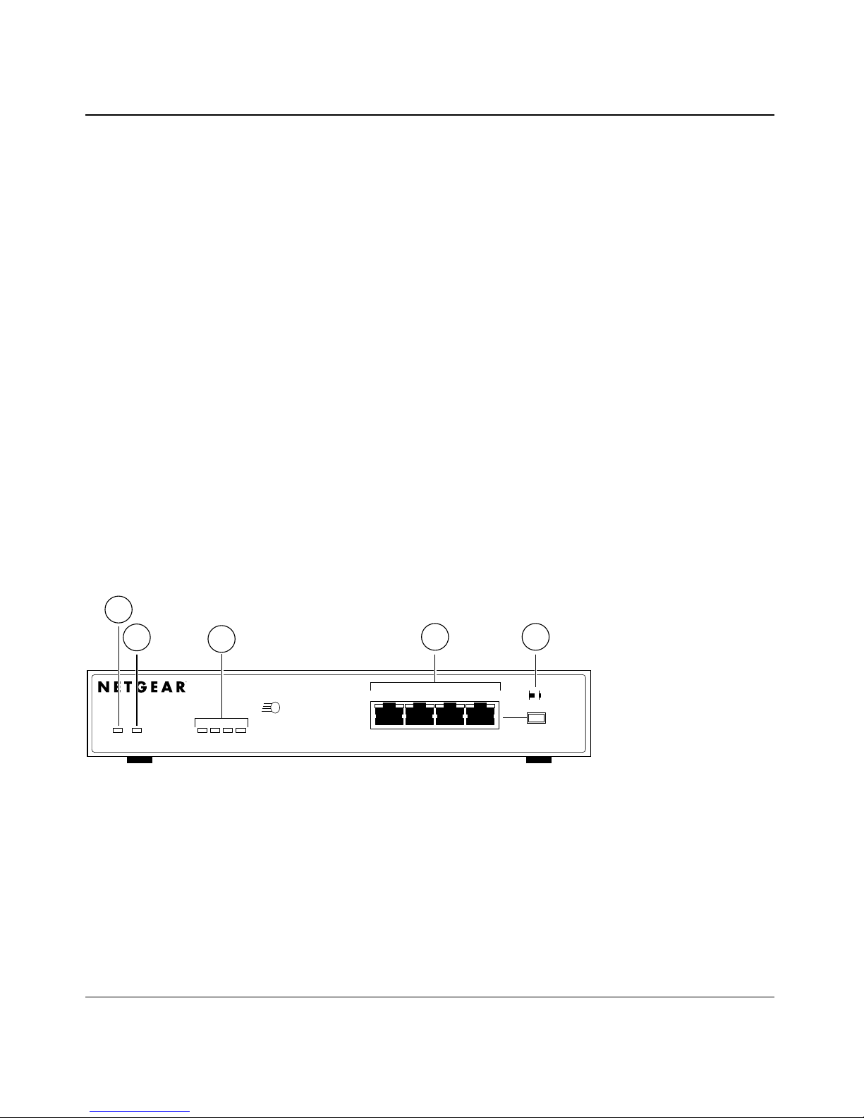
Front Panel
The front panel contains the LEDs, RJ-45 100BASE-TX port connectors, and Normal/Uplink push
button. Figure 2-1 shows the front panel of the Model FE104 hub, and Figure 2-2 shows the front
panel of the Model FE108 hub.
1
2
Pwr Col 1 10 20 >30
Key:
1 = Pwr (power) LED
2 = Col (collision) LED
3 = Utilization % LEDs
4 = RJ-45 ports with Link/Rx and Part (partition) LEDs on each port
5 = Normal/Uplink push button
3
100BASE-TX FAST ETHERNET HUB FE104
100 Mbps
Utilization %
F AST
123 4
4 5
Link/Rx Part
Normal/Uplink
186EA
Figure 2-1. Front panel of the Model FE104 Fast Ethernet Hub
Physical Description 2-1
Page 14
Installation Guide for the Model FE104 and Model FE108 Fast Ethernet Hubs
1
2
Pwr Col 1 10 20 >30
3
100BASE-TX FAST ETHERNET HUB FE108
Utilization %
100 Mbps
F AST
1234
4
Link/Rx Part
5668
5
Normal/Uplink
185EA
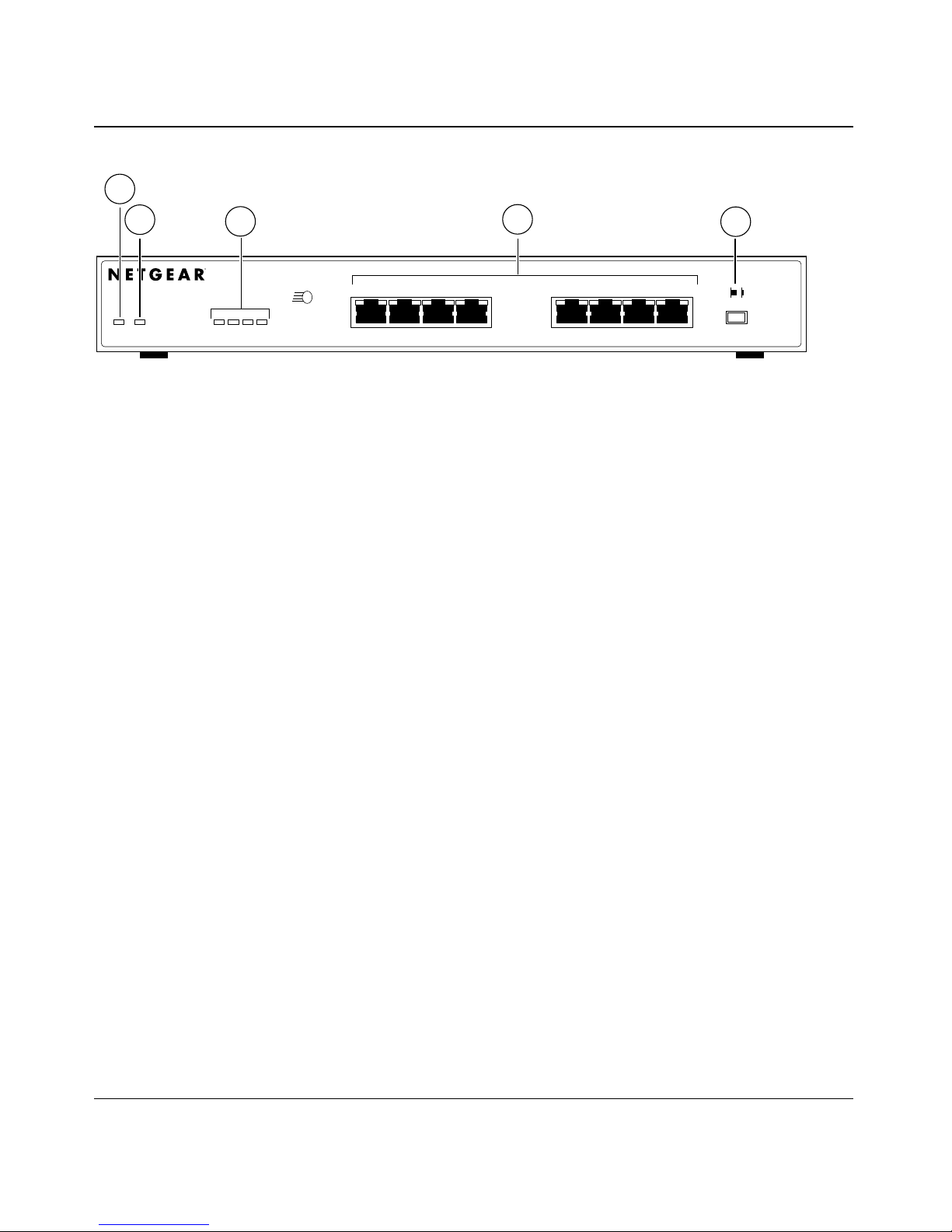
Key:
1 = Pwr (power) LED
2 = Col (collision) LED
3 = Utilization % LEDs
4 = RJ-45 ports with Link/Rx and Part (partition) LEDs on each port
5 = Normal/Uplink push button
Figure 2-2. Front panel of the Model FE108 Fast Ethernet Hub
LED Display
Three LEDs on the front panel of the hub and two on each port connector allow you to identify the
following information:
• Status of the hub power supply
• Collision occurrence on an Ethernet segment in a standalone hub or a stack of hubs
• Data utilization percentage of the Ethernet segment in a standalone hub or a stack of hubs
• Link and receive activity for all ports in the hub
• Partition status for all ports in the hub
2-2 Physical Description
Page 15

Installation Guide for the Model FE104 and Model FE108 Fast Ethernet Hubs
Table 2-1 describes each LED on the front panel of the hub.
Table 2-1. LED descriptions
Label Color Activity Description
Pwr Green On Power is supplied to the hub.
Col Yellow Blinking There is data collision on the network. Note that occasional
collisions are normal.
Link/Rx Green On
Blinking
Part Yellow On The port is being partitioned because of excessive collisions or
Utilization % Green On Four LEDs indicate whether the percentage of data utilization
The link between this port and the connecting port is good.
There is incoming data on the port.
jabber conditions.
on the hub or stack of hubs is 1%, 10%, 20%, or more than
30%.
RJ-45 100BASE-TX Ports
The front panel of the Model FE104 hub provides four RJ-45 100BASE-TX ports, and the Model
FE108 provides eight RJ-45 100BASE-TX ports. These standard RJ-45 connectors accept 2-pair
Category 5 UTP cable or 4-pair Category 5 UTP cable (100BASE-TX networks require only
2-pair wiring). The RJ-45 interface is an 8-pin connector.
Caution:
certified connector. Refer to Appendix C, “Fast Ethernet and Cabling Guidelines,” for
more information on cabling.
100 Mbps operation requires the use of Category 5 UTP cable with a 100 Mbps
An illustration of the RJ-45 connector and a table of pin assignments for the normal (MDI-X)
RJ-45 connector and the uplink (MDI) RJ-45 connector are in Appendix B, “RJ-45 Connector
Information.” Table B-1 provides the pinout information.
Physical Description 2-3
Page 16

Installation Guide for the Model FE104 and Model FE108 Fast Ethernet Hubs
As illustrated in Figure 2-3, two LEDs are positioned at the top corners of each RJ-45 connector.
The left indicator is the Link/Rx (receive) LED, and the right indicator is the P art (partition) LED.
Both LEDs are described in Table 2-1.
Link/Rx Part
184EA
Figure 2-3. Link/Rx and Part (partition) LEDs on the RJ-45 ports
Normal/Uplink Push Button
The Normal/Uplink push button on the front panel of the hub, as illustrated in Figure 2-4, allows
you to select uplink (MDI) or normal (MDI-X) wiring for Port 4 on the Model FE104 hub and Port
8 on the Model FE108 hub. Ports 4 and 8 are configured for normal wiring when the push b utton is
in the out position. When the push button is pressed in, Ports 4 and 8 are configured for uplink
wiring.
MODEL
Link/Rx Part
1234
Normal/Uplink
Model FE104 Model FE108
Figure 2-4. Normal/Uplink push button
FE104
Link/Rx Partition
12
Link/Rx Part
3
45678
Normal/Uplink
183EA
2-4 Physical Description
Page 17

Installation Guide for the Model FE104 and Model FE108 Fast Ethernet Hubs
The Normal/Uplink push button eliminates the need to use a crossover cable for daisy-chaining or
cascading. Use the following guidelines to configure Ports 4 and 8 for uplink or normal wiring:
• Configure Ports 4 and 8 for normal wiring if the port is to be connected to an uplink-wired
device, such as a network station or a PC.
• Configure Ports 4 and 8 for uplink wiring if the port is to be connected to a normal-wired
device, such as a 100 Mbps switch or another hub.
The remaining (normal) ports on the hubs cannot be configured for uplink wiring. If you are using
one of these ports to connect to another normal port, you must use an RJ-45 crossover cable to
connect the two ports (refer to Appendix C, “Fast Ethernet and Cabling Guidelines,” for
information on the crossover and straight-through cables).
Rear Panel
As illustrated in Figure 2-5 and Figure 2-6, the rear panel of each hub has a grounding clip and a
DC power receptacle that is provided for connection to the supplied DC power adapter.
Key:
1 = Grounding clip
2 = DC power receptacle
Figure 2-5. Rear panel of the Model FE104 hub
21
12 Vdc 1.2A
– +
196EA
Physical Description 2-5
Page 18

Installation Guide for the Model FE104 and Model FE108 Fast Ethernet Hubs
Key:
1 = Grounding clip
2 = DC power receptacle
Figure 2-6. Rear panel of the Model FE108 hub
21
12 Vdc 1.2A
– +
182EA
2-6 Physical Description
Page 19

This chapter provides information and procedures for:
• Preparing the site
• Checking package contents
• Installing a NETGEAR 100BASE-T hub
• Verifying your installation
Preparing the Site
Chapter 3
Installation
Before you begin installing the hub, prepare the installation site. Make sure the operating
environment meets the physical requirements of the equipment as listed in Table 3-1.
Table 3-1. Operating environment requirements
Characteristic Requirements
Temperature Ambient temperature between 0° and 40° C (32° F and 104° F).
No nearby heat sources such as direct sunlight, warm air exhausts, or heaters.
Humidity Between 5% and 85% noncondensing.
Ventilation Minimum 2 inches (5.08 cm) on all sides for cooling.
Adequate airflow in room or wiring closet.
Operating
conditions
Service access Minimum 12 inches (19.68 cm) front and back for service access and maintenance.
Power Adequate power source within 6 feet (1.83 m).
Wiring hardware Wiring hardware, such as punchdo wn bloc ks or patch panels, should be complete bef ore
At least 6 feet (1.83 m) to nearest source of electromagnetic noise (example is a
photocopy machine).
Front and back clearance for cables and wiring hardware such as punchdown blocks.
installing the hub.
Installation 3-1
Page 20

Installation Guide for the Model FE104 and Model FE108 Fast Ethernet Hubs
Checking Package Contents
This package should contain the following items:
• Model FE104 or Model FE108 Fast Ethernet Hub
• Rubber pads for tabletop installation
• DC power adapter
• Warranty and Owner Registration Card
• This manual
Call your reseller or customer support in your area if there are any wrong, missing, or damaged
parts. Refer to page iii for the location of customer support in your area.
Keep the carton, including the original packing materials. Use them to repack the hub if you need
to return it for repair.
To qualify for product updates and product warranty registrations, complete the Warranty and
Owner Registration Card within 30 days of purchase and return it to NETGEAR, Inc.
3-2 Installation
Page 21

Installation Guide for the Model FE104 and Model FE108 Fast Ethernet Hubs
Installing a NETGEAR 100BASE-TX Hub
This section provides information and instructions for installing the hub on a tabletop or any other
flat surface. For instructions on installing more than one hub, see “Installing Multiple Hubs” later
in this chapter.
There are certain guidelines to follow when installing 100 Mbps networks. The EIA/TIA 568-A
standard recommends the installation of Category 5 UTP cable to handle up to 100 MHz
bandwidth. Use the guidelines outlined in “Cable Guidelines” on page C-2 of Appendix C, “Fast
Ethernet and Cabling Guidelines,” to ensure that your cables perform to specifications.
Installing the Hub on a Flat Surface
To install the hub on a tabletop or another flat surface, follow these steps:
1.
Install self-adhesive pads on the bottom of the hub.
Peel off the protective backing from the rubber pads and apply one at each of the marked
locations on the bottom of the hub.
2.
Set the hub on a table or shelf so that it has at least 2 inches (5 cm) of space on all sides.
3.
Install any additional Fast Ethernet hubs in your stack.
The Model FE104 and Model FE108 hubs are Class II devices. Therefore, when stacking
hubs, connect the devices in daisy-chain style as illustrated in Figure 3-1. When connecting
more than two hubs, refer to “Installing Multiple Hubs.”
4.
Connect the devices to the ports on the hub using Category 5 UTP cable and connectors
to the RJ-45 connectors.
Refer to Appendix C, “Fast Ethernet and Cabling Guidelines,” for wiring rules and guidelines.
5.
Connect the DC power adapter cable when installation of each hub is complete.
Connect the DC power adapter cable to the power receptacle on the hub first and then connect
the power adapter to the wall.
6.
Continue with the steps in “Verifying Your Installation” later in this chapter.
Installation 3-3
Page 22

Installation Guide for the Model FE104 and Model FE108 Fast Ethernet Hubs
Installing Multiple Hubs
This section provides you with information about installing multiple hubs. As illustrated in
Figure 3-1, two hubs can be simply daisy-chained together. In Figure 3-2, multiple hubs are
connected to a server through the Model FS104 10/100 Mbps Fast Ethernet Switch.
After you have installed your hubs using one of the methods shown, connect the power adapter to
the wall, and proceed to “V erifying Y our Installation.”
1
Model FE108 hub
Key:
1 = Model FE108 Fast Ethernet Hub (Normal/Uplink push button set in Uplink position)
2 = Model FE108 Fast Ethernet Hub (Normal/Uplink push button set in Normal position)
3 = PCs with 100 Mbps connection
Model FE108 hub
3
Figure 3-1. Daisy-chaining two Model FE108 hubs
2
359EA
3-4 Installation
Page 23

Installation Guide for the Model FE104 and Model FE108 Fast Ethernet Hubs
2 3 41
Model FS104
switch
Model FE104 hub Model FE108 hub
5 5
7 9
Key:
1 = 100 Mbps connection
2 = Server
3 = FS104 10/100 Mbps switch (Normal/Uplink push button set in Normal position)
4 = 10 Mbps connection
5 = PCs with 100 Mbps connection to Fast Ethernet hub
6 = PCs with 10 Mbps connection to Ethernet hub
7 = Model FE104 Fast Ethernet Hub (Normal/Uplink push button set in Uplink position)
8 = Model FE108 Fast Ethernet Hub (Normal/Uplink push button set in Uplink position)
9 = Model EN108 Ethernet hub (Normal/Uplink push button set in Uplink position)
8
Model EN108 hub
Figure 3-2. Connecting multiple hubs
6
199EA
Installation 3-5
Page 24

Installation Guide for the Model FE104 and Model FE108 Fast Ethernet Hubs
Verifying Y our Installation
When installation is complete and power has been applied to the hub, the following conditions
should exist:
• The Pwr (power) LED on the front panel is on.
• The Link/Rx LED on each connected port is on.
• The Link/Rx LED on the connected port is blinking when data is being received by that port.
• The Utilization % LED on the front panel is on and shows the percentage of utilization when
data is being received by any port on the hub.
If there are any problems, refer to Chapter 4, “Troubleshooting.”
3-6 Installation
Page 25

Chapter 4
Troubleshooting
This chapter provides information about troubleshooting the Model FE104 and Model FE108
hubs.
Troubleshooting the Hub and the Network
To troubleshoot the hub and the network, refer to Table 4-1.
Table 4-1. Troubleshooting
Symptom Activity Check
No power at hub Pwr (power) LED off Check the power cord connections and make sure the ends
are properly plugged into the hub and the wall outlet.
Port connection
not functioning
Link/Rx LED off or
intermittent
If the Link/Rx LED is not lit on an active port, check the
attached device and make sure it is switched on and that
there is a proper connection at that end.
If the Link/Rx LED is intermittent, check the port termination
at both the hub and device ends. Check the crimp on the
RJ-45 connectors. In a F ast Ethernet operation, the quality of
the crimp on the connector is important. It is also important
that only Category 5 cable is used and that it is certified for
100 Mbps operation.
Check that the length of the UTP cable from the hub to the
device does not exceed 328 feet (100 m).
Note: Under normal operation, the Link/Rx LED will blink
when data is received on that port.
Troubleshooting 4-1
Page 26

Installation Guide for the Model FE104 and Model FE108 Fast Ethernet Hubs
Table 4-1. Troubleshooting (continued)
Symptom Activity Check
Port connection not
functioning
Problems with Port 4
on the Model FE104
hub or with Port 8 on
the Model FE108 hub
Col (collision) LED
blinking
Link/Rx LED off
or intermittent
Link/Rx LED off Check the Normal/Uplink push button on the front panel.
Col LED on Collisions are normal on Ethernet networks and occur when
Make sure that the network adapter card installed in the PC
is in working condition and that the computer and hub are
turned on. Verify that the network adapter card is100 Mbps
capable and that the 100 Mbps LED and Link LEDs are on at
the network adapter card in the PC.
If the Link/Rx LED is not lit after cabling has been installed,
check that the proper cable is installed, and check for
miswired cable pairs or loose connectors. Be sure that there
is power to both the hub and the connected PC.
If you are using a straight-through cable connected to a PC
or other MDI-wired device, make sure the Normal/Uplink
push button is set in the Normal position.
If you are using a straight-through cable connected to a
router or another hub, make sure the Normal/Uplink push
button is set in the Uplink position.
Try the alternate position of the Normal/Uplink push button to
turn the Link/Rx LED on.
two or more computers transmit data on the network
simultaneously. Computers that caused the collision retry
transmission at different intervals until the transmission
succeeds. Excessive collisions can result when multiple hubs
are connected and when many computers are connected on
the network. Incorrect cabling, connectors, and wiring
techniques are other causes for excessive collisions.
4-2 Troubleshooting
Page 27

Chapter 5
Network Configuration
This chapter provides an overview of the levels of service that are provided by incorporating
NETGEAR Ethernet hubs and switches into your network. Examples are given to illustrate the
function of the hubs and switches in several configurations that provide those different levels of
service to network users.
Combining 10BASE-T, 100BASE-T, and switching technology provides for four distinct le v els of
service:
• 10BASE-T hub provides shared bandwidth of 10 Mbps for the group of active users.
• 10BASE-T switch provides dedicated bandwidth of 10 Mbps for each user.
• 100BASE-TX hub provides shared bandwidth of 100 Mbps for the group of active users.
• 100BASE-TX switch provides dedicated bandwidth of 100 Mbps for each user.
These services can be combined to create customized network configurations.
Note:
that you use all Category 5 cabling so connections can be switched between 10 and 100
Mbps devices. NETGEAR also recommends that you use dual-speed (10/100) Ethernet
adapters in all devices so that they can be attached to any 10 or 100 Mbps hub or switch.
When integrating a 10 Mbps and a 100 Mbps network, NETGEAR recommends
Configuration Examples
The Model FE104 and Model FE108 hubs are designed to provide flexibility in configuring your
network connections. Each hub can be used as a standalone device or can be used with other 100
Mbps repeaters, switching hubs, or other interconnection devices in various configurations. These
configuration examples show the integration of the hub in network environments of all sizes and
types, whether in a network of a few PCs connected to a printer or in a segmented network with
multiple users or workgroups and other networking devices.
Network Configuration 5-1
Page 28

Installation Guide for the Model FE104 and Model FE108 Fast Ethernet Hubs
100BASE-TX Shared Repeater
In the configuration for 100BASE-TX shared repeaters, the Model FE104 and Model FE108 hubs
are used in a 100 Mbps network. As illustrated in Figure 5-1, the Model FE104 and Model FE108
hubs can be used in a standalone network with users attached directly to the hub.
21 3
Model FE104 hub
Key:
1 = PCs
2 = 100 Mbps connection
3 = Model FE104 Fast Ethernet Hub or Model FE108 Fast Ethernet Hub
(Normal/Uplink push button set in Normal position on both hubs)
4 = Server
4
21 3
Model FE108 hub
4
188EA
Figure 5-1. Model FE104 and Model FE108 hubs as standalone hubs
Migrating to 100 Mbps Operation
One of the more common problems affecting network performance is congestion. In many local
area network (LAN) environments, the primary problem is access to the server. When many users
are connected and accessing one server on a 10 Mbps link, congestion and collisions may occur
more frequently, resulting in low data throughput. As illustrated in Figure 5-2, adding a Model
FE104 or Model FE108 hub allows power users to be grouped together in the 100 Mbps Fast
Ethernet network, isolated from the 10 Mbps network users who need occasional server access. By
adding a NETGEAR Model SW502 Ethernet Switch that has one 10 Mbps port and one 100 Mbps
port, the existing 10 Mbps users can access the server through the 100 Mbps port on the Model
SW502 switch. This configuration forms a mixed-speed network and provides transparent
communication among 10 Mbps users and 100 Mbps users.
5-2 Network Configuration
Page 29

Installation Guide for the Model FE104 and Model FE108 Fast Ethernet Hubs
Model EN516 hub
217 3
Model FE104 hub
Model SW502 switch
Model EN516 hub
654
21
Model EN516 hub
8
7
7
8
217EA
Key:
1 = PCs with 100 Mbps connections
2 = 100 Mbps connection
3 = Model FE104 Fast Ethernet Hub (Normal/Uplink push button set in Normal position)
4 = Server
5 = Model SW502 switch (Normal/Uplink push button set in Uplink position on port connected to Model FE104 Fast
Ethernet Hub (Normal/Uplink push button set in Normal position on port connected to Model EN516 Ethernet Hub.)
6 = 10 Mbps connection
7 = Model EN516 Ethernet Hub (Normal/Uplink push button set in Uplink position)
8 = PCs with 10 Mbps connections
Figure 5-2. Using the Model FE104 hub to migrate your network to 100 Mbps
Network Configuration 5-3
Page 30

Installation Guide for the Model FE104 and Model FE108 Fast Ethernet Hubs
Multiport Switch with Fast Ethernet Backbone
If the 10 Mbps shared repeater portion of the network experiences congestion, you can use the
Model SW507 Ethernet Switch with six 10 Mbps ports and one 100 Mbps port to segment the
10 Mbps traffic on the hubs. As illustrated in Figure 5-3, adding the switch increases overall
bandwidth and throughput because the traffic from one 10 Mbps segment passes to the other
segment only when addressing a node on one of the other segments.
65421 3
Model FE108 hub
Model SW507 switch
Model EN516 hub Model EN516 hub Model EN516 hub
7 7 7
216EA
Key:
1 = PCs with 100 Mbps connection
2 = 100 Mbps connection
3 = Model FE108 Fast Ethernet Hub (Normal/Uplink push button set in Normal position)
4 = Server
5 = Model SW507 switch (Normal/Uplink push button set in Uplink position)
6 = 10 Mbps connection
7 = Model EN516 Ethernet Hubs (Normal/Uplink push button set in Uplink position)
Figure 5-3. Multiport switch with Fast Ethernet backbone
5-4 Network Configuration
Page 31

Appendix A
Technical Specifications
This appendix provides technical specifications for the NETGEAR Model FE104
and Model FE108 Fast Ethernet Hubs.
General Specifications
Network Protocol and Standards Compatibility
IEEE 802.3u 100BASE-TX, Fast Ethernet
IEEE 802.3 CSMA/CD
Data Rate
100 Mbps with 4B/5B encoding and MLT-3 physical interface for 100BASE-TX
Interface
RJ-45 connector for 100BASE-T Ethernet interface
Electrical Specifications
Power consumption: 4 W (Model FE104 hub)
8 W (Model FE108 hub)
Physical Specifications
Dimensions:
Width 6.2 inches (15.8 cm) (Model FE104 hub)
9.27 inches (23.5 cm) (Model FE108 hub)
Height 1.06 inch (2.7 cm)
Depth 4.1 inches (10.3 cm)
Weight: 17.5 ounces (495 g) (Model FE104 hub)
25.8 ounces (730 g) (Model FE108 hub)
Technical Specifications A-1
Page 32

Installation Guide for the Model FE104 and Model FE108 Fast Ethernet Hubs
Environmental Specifications
Operating temperature: 0° C to 40° C (32° F to 104° F)
Storage temperature: –25
°
C to 70° C (–13° F to 158° F)
Operating humidity: 80% maximum relative humidity, noncondensing
Storage humidity: 95% maximum relative humidity, noncondensing
Operating altitude: 10,000 ft (3,000 m) maximum
Storage altitude: 10,000 ft (3,000 m) maximum
Electromagnetic Emissions
Meets requirements of:
CE mark, commercial
FCC Part 15, Class A
EN 55 022 (CISPR 22), Class A
VCCI Class I ITE
Electromagnetic Susceptibility
CE mark, commercial
Electrostatic discharge (ESD): IEC 801-2, Level 2/3/4
Radiated electromagnetic field: IEC 801-3, Level 2
Electrical fast transient/burst: IEC 801-4, Level 2
Electrical surge: IEC 801-5, Level 2
Safety Agency Approvals
CE mark, commercial
UL listed (UL 1950)
CSA certified (CSA 22.2 #950)
TUV licensed (EN 60 950)
T-Mark
A-2 Technical Specifications
Page 33

Appendix B
RJ-45 Connector Information
This appendix provides information about the RJ-45 connectors used for the Model FE104 and
Model FE108 Fast Ethernet Hubs.
The IEC 603-7 8-pin modular connector, commonly called an RJ-45 connector, is used to connect
stations, hubs, and switches through unshielded twisted pair (UTP) cable and supports 100 Mbps
data transmission. The RJ-45 connector accepts 2- or 4-pair Category 5 UTP cable.
In a Fast Ethernet network, it is important that all 100BASE-T certified Category 5 cabling use
Category 5 RJ-45 connectors. It is common practice to use Category 5 UTP cable with Category 3
connectors. However, 100 Mbps operation is compromised when the mixed configuration is used.
Figure B-1 illustrates the RJ-45 connector used for port connections on hubs. Table B-1 provides
the pinout information for the normal (MDI-X) RJ-45 connector and for the uplink (MDI) port
(Port 4 on the Model FE104 and Port 8 on the Model FE108) RJ-45 connector.
18
7177
Figure B-1. RJ-45 connector
RJ-45 Connector Information B-1
Page 34

Installation Guide for the Model FE104 and Model FE108 Fast Ethernet Hubs
Table B-1. RJ-45 connector pinouts
Pin Normal (MDI-X) Uplink (MDI) *
1 Input Receive Data + Output Transmit Data +
2 Input Receive Data - Output Transmit Data 3 Output Transmit Data + Input Receive Data +
6 Output Transmit Data - Input Receive Data 4, 5, 7, 8 Internal termination, not used for data transmission
* Applicable to Port 4 on the Model FE104 hub and Port 8 on the Model FE108 hub, when the Normal/Uplink
push button is in the Uplink position.
B-2 RJ-45 Connector Information
Page 35

Appendix C
Fast Ethernet and Cabling Guidelines
This appendix discusses the Fast Ethernet technology and the cable specifications and guidelines
for Category 5 UTP cabling.
Fast Ethernet Technology
Fast Ethernet is conventional Ethernet but faster. Fast Ethernet, or 100BASE-TX, operates at
100 Mbps instead of 10 Mbps. The 100BASE-TX technology uses the same frame format and
length as Ethernet and does not require changes to the upper-layer protocols, applications, or
networking software that run on LAN workstations. You can switch and route data from 10 Mbps
to 100 Mbps without protocol translation and its associated delays. Fast Ethernet is based on the
proven CSMA/CD Media Access Control (MAC) Protocol.
The most popular cabling scheme in an Ethernet network today is star-wired topology, where the
hub is in a central wiring closet and individual cables run out to each tabletop device. This
topology is the same topology used by Fast Ethernet, although the maximum allowable network
diameter is smaller because of the increase in packet speed.
Fast Ethernet and Cabling Guidelines C-1
Page 36

Installation Guide for the Model FE104 and Model FE108 Fast Ethernet Hubs
Fast Ethernet Cabling
In a Fast Ethernet network, certain rules and regulations must be followed. This section discusses
the following aspects of cabling:
• Cable guidelines
• Cable lengths within a network
• Category 5 specifications
• Crossover and straight-through twisted pair cables
• Patch panels
• Near end crosstalk
Cable Guidelines
Fast Ethernet uses UTP cable, as specified in the IEEE 802.3u standard for 100BASE-T. The
specification recommends Category 5 UTP cable consisting of either 2-pair or 4-pair twisted
insulated copper conductors bound in a single plastic sheath. Category 5 cable is certified up to
100 MHz bandwidth. 100BASE-TX operation uses one pair of wires for transmission and the
other pair for receiving and for collision detection.
When installing Category 5 UTP cabling, use the following guidelines to ensure that your cables
perform to the following specifications:
• Certification. Make sure that your Category 5 UTP cable has completed the Underwriters
Laboratories (UL) or Electronic Testing Laboratories (ETL) certification process.
• Termination method. To minimize crosstalk noise, maintain the twist ratio of the cable up to
the point of termination; untwist at any RJ-45 connector or patch panel should not exceed
0.5 inch (1.5 cm).
C-2 Fast Ethernet and Cabling Guidelines
Page 37

Installation Guide for the Model FE104 and Model FE108 Fast Ethernet Hubs
Cable Lengths
Category 5 distributed cable that meets ANSI/EIA/TIA-568-A building wiring standards can be a
maximum of 328 feet (100 m) in length, divided as follows:
• 20 feet (6 m) between the hub and the patch panel (if used)
• 295 feet (90 m) from the wiring closet to the wall outlet
• 10 feet (3 m) from the wall outlet to the desktop device
The patch panel and other connecting hardware must meet the requirements for 100 Mbps
operation (Category 5). Workmanship quality is a must. Only 0.5 inch (1.5 cm) of untwist in the
wire pair is allowed at any termination point.
Cable Specifications
Table C-1 lists the electrical requirements of the Category 5 cable.
Table C-1. Electrical requirements of Category 5 cable
Specification Requirements
Number of pairs Two or Four
Impedance 100 Ω ± 15%
Mutual capacitance at 1 KHz 5.6 nF per 100 m
Maximum attenuation
(dB per 100 m, at 20°C) at 16 MHz: 8.2
at 31 MHz: 11.7
at 100 MHz: 22
NEXT loss (dB minimum) at 16 MHz: 44
at 31 MHz: 39
at 100 MHz: 32
Fast Ethernet and Cabling Guidelines C-3
Page 38

Installation Guide for the Model FE104 and Model FE108 Fast Ethernet Hubs
Twisted Pair Cables
For two devices to communicate, the transmitter of each device must be connected to the receiver
of the other device. The crossover function is usually implemented internally as part of the
circuitry in the device. Computers and workstation adapter cards are usually media-dependent
interface ports, called MDI or uplink ports. Most repeaters and switch ports are configured as
media-dependent interfaces with built-in crossover ports, called MDI-X or normal ports. Refer to
the instructions in Chapter 3, “Installation,” for appropriate cable use and connection.
Figure C-1 illustrates straight-through twisted pair cable connections, and Figure C-2 illustrates
crossover twisted pair cable connections.
1
Tx
2
1
3
Rx
6
Key:
1 = Uplink or MDI port
2 = Normal or MDI-X port
1
Rx
2
3
Tx
6
Figure C-1. Straight-through twisted pair cable
1
Rx
2
1
1
Rx
2
2
7181
2
3
Tx
6
Key:
1 = Normal or MDI-X port
2 = Normal or MDI-X port
Figure C-2. Crossover twisted pair cable
C-4 Fast Ethernet and Cabling Guidelines
3
Tx
6
7182
Page 39

Installation Guide for the Model FE104 and Model FE108 Fast Ethernet Hubs
Patch Panels and Cables
If you are using patch panels, make sure that they meet the 100B ASE-T requirements. NETGEAR
recommends Category 5 UTP cable for all patch cables and work area cables to ensure that your
UTP patch cable rating meets or exceeds the distribution cable rating.
To wire patch panels, you need two Category 5 UTP cables with an RJ-45 connector at each end,
as shown in Figure C-3.
1
87654321
Key:
1 = RJ-45 connector
2 = Category 5 UTP patch cable
2 1
87654321
5525.1
Figure C-3. Category 5 UTP patch cable with male RJ-45 connector at each end
Note: Flat “silver satin” telephone cable may have the same RJ-45 connector. However,
using telephone cable will result in excessive collisions and cause the attached port to be
partitioned or disconnected from the network.
Fast Ethernet and Cabling Guidelines C-5
Page 40

Page 41

Numerics
Index
100BASE-T hub installation 3-3
A
access requirements 3-1
C
cable
Category 5 UTP 5-1, C-2, C-3, C-5
Category 5 UTP, troubleshooting 4-1
crossover 2-5, C-4
guidelines C-3
specifications (table) C-3
straight-through 2-5, 4-2, C-4
termination method C-2
troubleshooting UTP 4-1
Category 5 UTP cable
length guidelines C-3
port connection problems with 4-1
specifications (table) C-3
troubleshooting 4-1
using for 100 Mbps migration 5-1
using with RJ-45 connector 2-3
Col (collision) LED 2-1, 2-2
configuration examples
100BASE-TX shared repeater 5-2
migrating to 100 Mbps 5-2
multiport switch 5-4
small organizations 5-2
crossover cable C-4
customer support iii
E
Ethernet
cabling guidelines C-2
technology C-1
F
features 1-2
front panel
Model FE104 hub 2-1
Model FE108 hub 2-2
H
humidity requirements 3-1
I
installation
100BASE-TX hub 3-3
multiple hubs 3-4
on a flat surface 3-3
verifying 3-6
Index 1
Page 42

Installation Guide for the Model FE104 and Model FE108 Fast Ethernet Hubs
L
LEDs
Col (collision) 2-3, 4-2
description (table) 2-3
Link/Rx 2-3, 2-4, 3-6
Link/Rx, troubleshooting 4-2
overview 1-2
Part (partition) 2-3, 2-4
Pwr (power) 2-3, 3-6
table 2-3 2-3
troubleshooting 4-2
Utilization % 2-3, 3-6
Link/Rx LED 2-3, 2-4, 3-6
M
MDI wiring. See normal wiring
MDI-X wiring. See uplink wiring
migration to 100 Mbps 1-1, 5-2
multiple hub installation 3-4
N
network adapter cards, troubleshooting 4-2
normal wiring 2-4, 2-5, 4-2, C-4
Normal/Uplink push button 1-2, 2-1, 2-2, 2-4,
4-2
O
operating conditions 3-1
P
package contents 3-2
Part (partition) LED 2-3, 2-4
patch panel C-3, C-5
Port 4
configuring 2-4
pinout information (table) B-2
troubleshooting 4-2
Port 8
configuring 2-4
pinout information (table) B-2
troubleshooting 4-2
ports, RJ-45 2-1, 2-2, 2-3, 2-4
power requirements 3-1
Pwr (power) LED 2-1, 2-3, 3-6
R
rear panel 2-5
requirements
access 3-1
cabling 2-3, 3-3, C-2
humidity 3-1
operating conditions 3-1
power 3-1
temperature 3-1
ventilation 3-1
wiring 3-1
RJ-45 connector
pinouts (table) B-2
troubleshooting 4-1
using for patch cables C-5
RJ-45 ports 2-3, 2-4
2 Index
Page 43

Installation Guide for the Model FE104 and Model FE108 Fast Ethernet Hubs
S
site preparation 3-1
straight-through cable 2-5, 4-2
T
technical specifications A-1
temperature requirements 3-1
troubleshooting
COL LED blinking 4-2
Link/Rx LED intermittent 4-1
Link/Rx LED off 4-1, 4-2
network adapter cards 4-2
Normal/Uplink push button 4-2
Port 4 4-2
Port 8 4-2
port connection 4-1, 4-2
Pwr LED off 4-1
RJ-45 connectors 4-1
UTP cable 4-1
U
unshielded twisted pair cable. See UTP cable
uplink wiring 2-4, B-1, C-4
Utilization % LED 2-3, 3-6
UTP cable
Category 5 C-2
troubleshooting 4-1
V
ventilation requirements 3-1
verifying installation 3-6
W
wiring requirements 3-1
W orld Wide Web iii
Index 3
Page 44

 Loading...