

Page 1
en
Service Manual Coffee Machine
EF 748
EF 749
1
01.2004 DOG
Page 2

Contents
Main Components ........................................................ 5
Overview ....................................................................................... 5
Jaw ................................................................................................ 6
Overview of rating plates .............................................................. 7
Water circuit .................................................................................. 8
Technical Data ............................................................................... 9
Operation .................................................................... 10
Preparation .................................................................................. 10
Making coffee ............................................................................... 11
Preparing hot water ..................................................................... 11
Frothing aids ............................................................................... 12
Heating with steam ..................................................................... 12
Frothing ....................................................................................... 12
LED status diagram .................................................................... 13
Troubleshooting ......................................................... 14
Checking the machine - receipt (1) ............................................ 14
Checking the machine - receipt (2) ............................................ 15
Coffee temperature too low ........................................................ 16
Coffee temperature too high ...................................................... 16
No function .................................................................................. 16
No outflow ................................................................................... 17
No steam function or too little steam ......................................... 18
No capsule ejection .................................................................... 18
Jaw does not close ..................................................................... 18
Water on the jaw ......................................................................... 18
Water on side of machine or below machine............................. 19
Pump noisy ................................................................................. 19
Not enough froth when frothing milk ......................................... 19
2
Page 3

Contents
Repair .......................................................................... 20
General disassembly (stage 1) ................................................... 20
General disassembly (stage 2) ................................................... 21
Replacing thermoblock .............................................................. 22
Replacing NTC ............................................................................ 22
Replacing pump .......................................................................... 23
Replacing fine-wire fuse ............................................................. 24
Replacing control board ............................................................. 25
Replacing main switch or steam switch .................................... 26
Replacing LED ............................................................................ 26
Replacing steam pipe ................................................................. 26
Replacing jaw .............................................................................. 27
Complete jaw disassembly ......................................................... 28
Complete jaw disassembly ......................................................... 29
Replacing heating PTC ............................................................... 30
Replacing pyramid plate ............................................................. 31
Replacing capsule cage ............................................................. 31
Electronic mainboard, wiring diagram ....................................... 32
Maintenance................................................................ 33
Descaling .................................................................................... 33
Measuring rate of flow ................................................................ 35
Checking for leaks and pump pressure (1) ................................ 36
Checking for leaks and pump pressure (2) ................................ 37
Checking extraction chamber for leaks ..................................... 38
Measuring coffee temperature ................................................... 39
Measuring closing force ............................................................. 40
Checking reed contact ................................................................ 41
Daily maintenance and final cleaning ........................................ 42
Spare parts ................................................................. 43
3
Page 4
Preface
The purpose of this Service Manual is to provide the service personnel with all necessary
information with regards to correct handling, maintenance and repair of the coffee machine
EF 748 and EF 749.
This manual should be used by the technicians as a valuable aid to guarantee the permanent
readiness for use of the machine. In order to take full advantage of all the functions, it is
absolutely necessary to follow the instructions in this manual.
Please keep this manual together with the corresponding service documentation. This way
you are assured to have the necessary information.
For fast access to information directly from the PC or MAC monitor, this manual is also
available on CD-ROM. The required utility (Adobe Acrobat), also on this CD-ROM, runs on PC
and MAC computers. At the Internet address www.adobe.com you can obtain the utility Adobe
Acrobat for additional platforms, free of charge.
4
Page 5
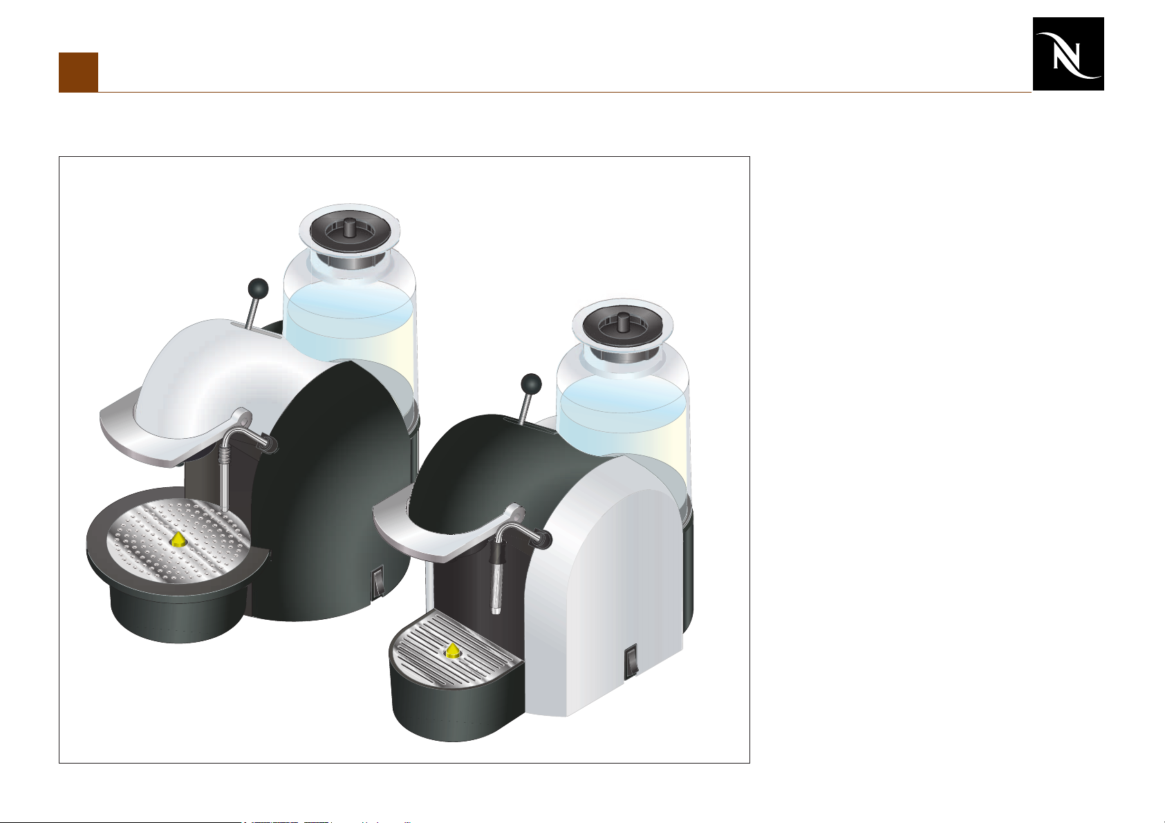
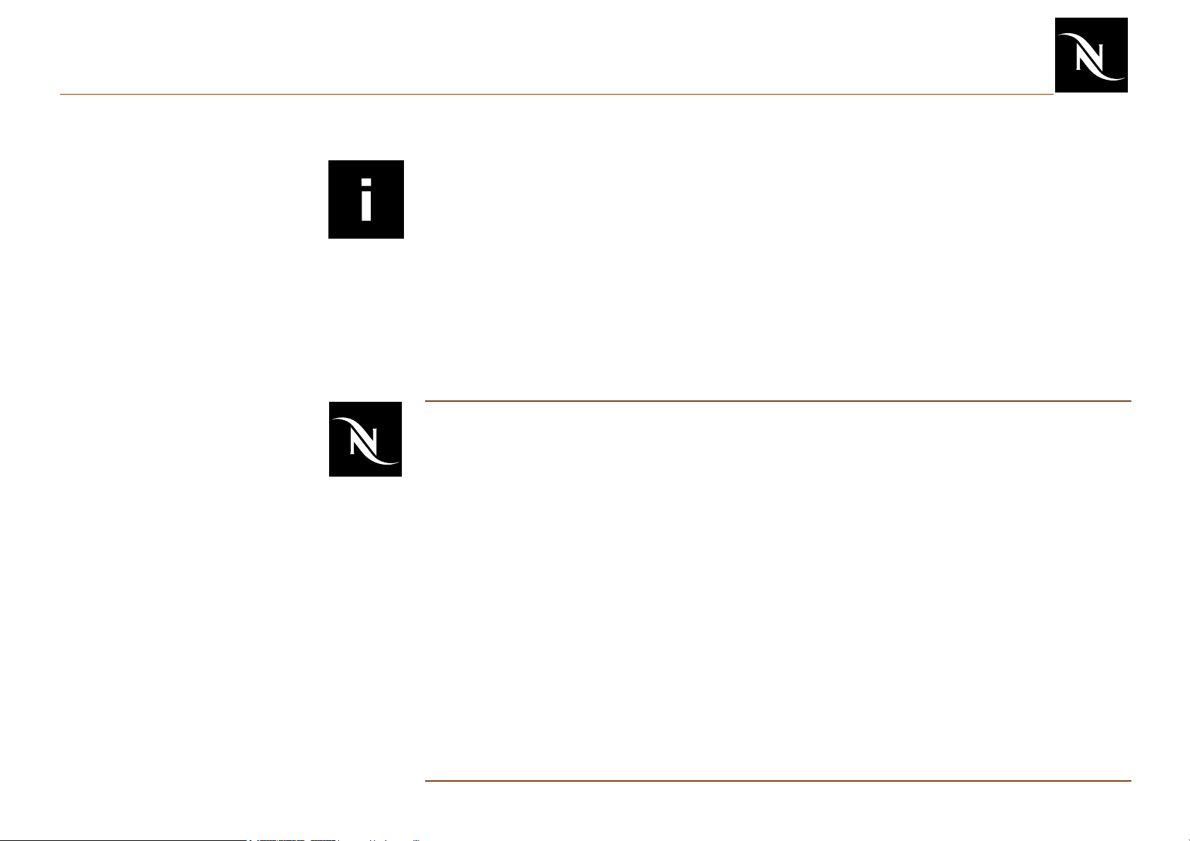
Main Components
Overview
1 Switch On/ Off
2 Switch steam
3 Upper part Jaw
4 Lower part Jaw
5 LED
6 Electronic mainboard
7 Steam pipe
8 Frothing aid
9 Floater
10 Drip tray
11 Drip grid
12 Closing handle
13 Jaw stick coffee / hot water
14 Water tank
15 Water tank connector
16 Condensation room
17 Thermoblock
18 Pump
19 Container for used capsules
12
1
3
4
5
7
6
13
14
16
15
11
10
8
9
19
17
18
2
5
Page 6
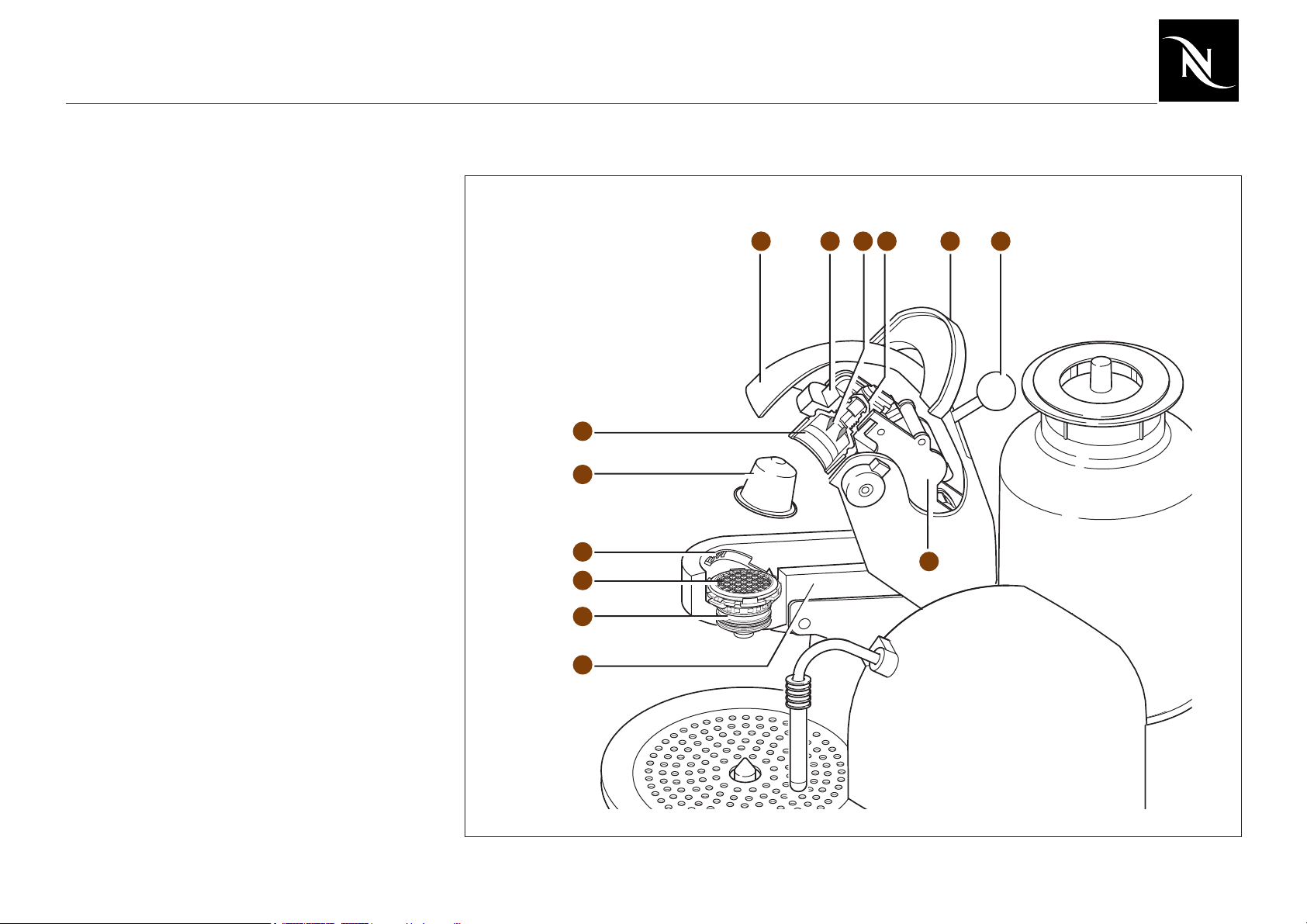
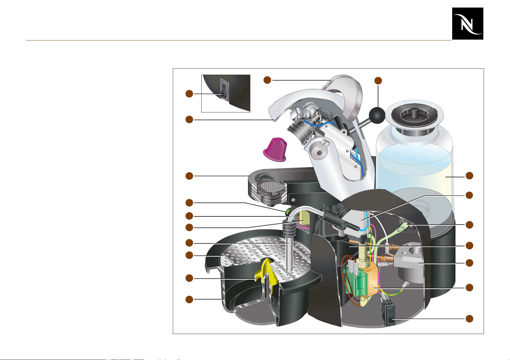
Main Components
Jaw
20 Support for brewing unit
21 Capsule cage
22 Closing handle
23 Jaw stick coffee, hot water/ steam
24 Blades
25 Cover
26 Heating PTC (until Sept. 2003 only)
27 Coffee capsule
28 Ejector
29 Pyramid plate (PPP, plastic)
30 Pyramid plate support
31 Brewing unit with ceramic valve and
reed contact board
32 Capsule cage connection
21
27
26
3225
22 2324
28
29
30
20
31
6
Page 7
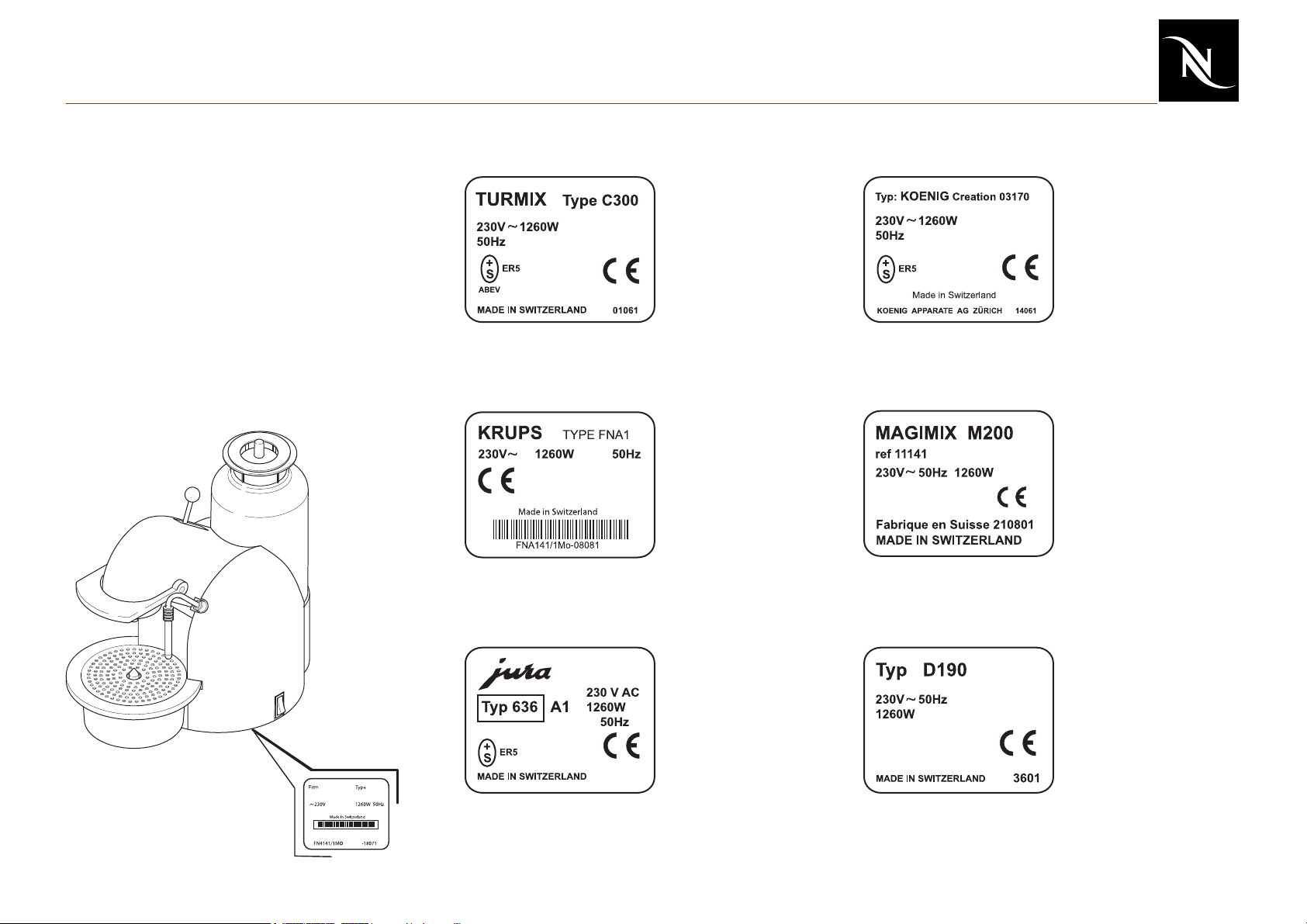
Main Components
Overview of rating plates
Depending on the brand, the rating plate may
be of varying design.
The rating plates carry the following
information:
Turmix
Date code
DDMMY
Krups
FNA141 = type
1M = factory
0 = internal number
08081 = Date code
DDMMY
König
03170 = Item number
with colour code
Date code DDMMY
Magimix
M200 = type code
Item number with colour
and country coding
Date code DDMMYY
Jura
636 = type
A = colour code
1 = Appliance
modification status
7
Saeco
Date code WWYY
Page 8
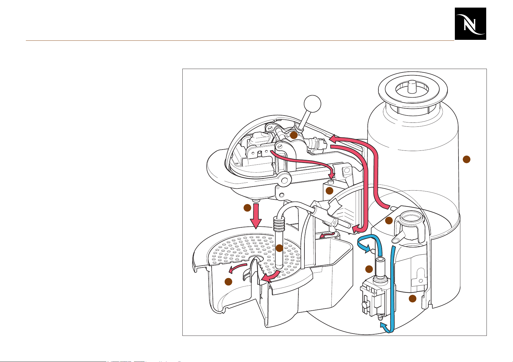
Main Components
Water circuit
1 Water tank
2 Water tank valve
3 Pump
4 Thermoblock
5 Ceramic valve
6 Coffee outlet
7 Steam pipe and frothing aid
8 Condensation room
9 Drip tray
5
1
8
6
2
7
3
9
4
8
Page 9
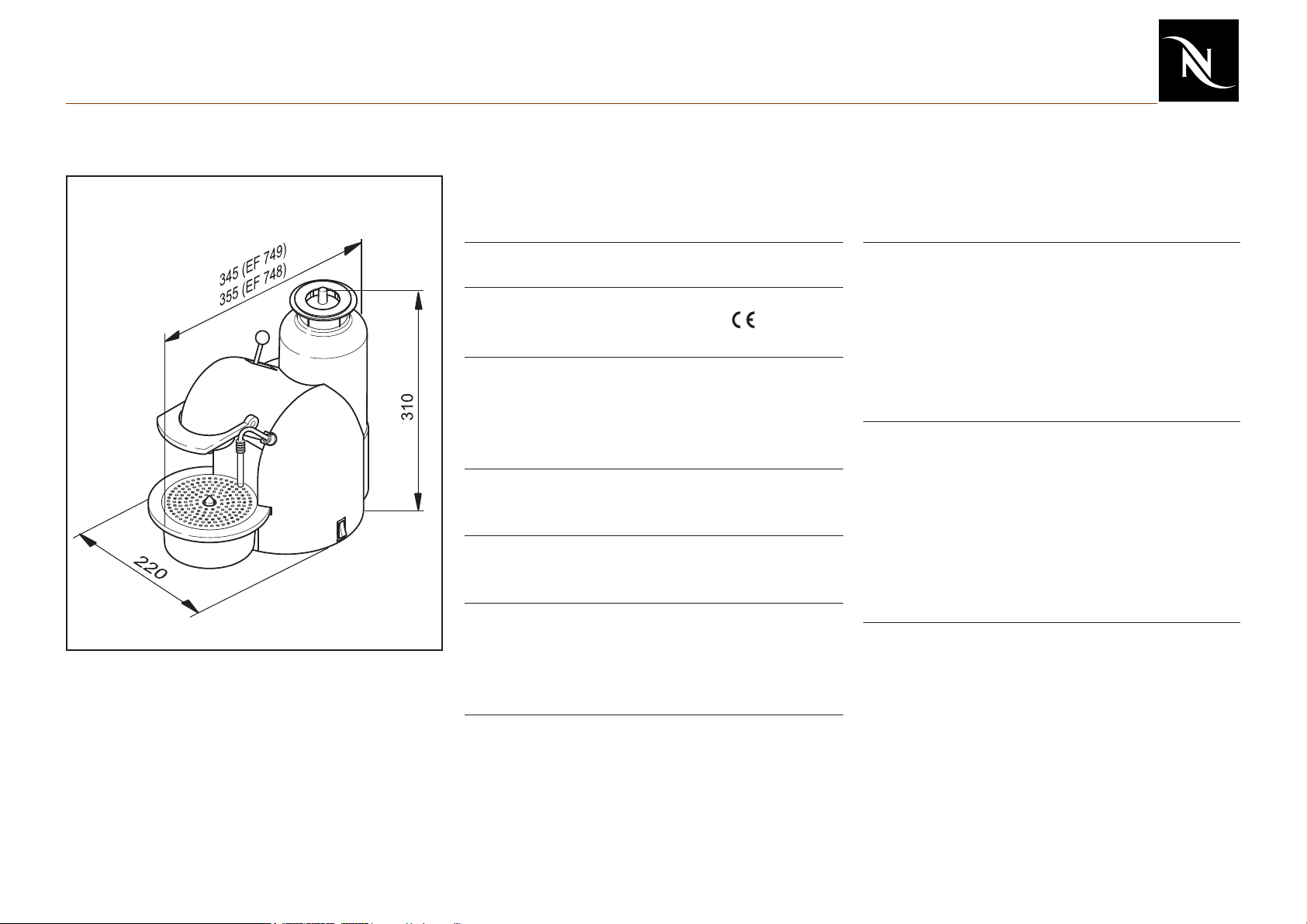
Main Components
Technical Data
Dimensions in mm
Mains EUR: 230V / 50 Hz
USA /CAN:120 V / 60 Hz
JAP: 110 V / 50-60 Hz
Cable length ~1,5 m
Approvals SEV, CENELEC, - conform
UL, CUL, MITI
Pump pressure:
- max. permissible 17,5 bar ±1,5 bar
- during coffee preparation 9 - 13 bar
(depending on brand of coffee)
Flow performance
100 - 240 ml/min. at 12 bar
Weight of machine 4,8 kg
(without water)
Capacities
Water tank 1.2 l
Drip tray 0.45 l
Capsule container 10-12 pcs.
Pre-heating time approx. ca. 45 s
Safety temperature (thermal cut-off) 184° C
Power consumption
(at all voltages and frequencies):
Heating 1’200 W
Pump 60 W
Heating PTC 15 W
Ratings:
Preheating 15.5 Wh
1 small cup (45ml) 5.5 Wh
1 large cup (110ml) 9 Wh
Stand-by mode (24 hours) 575 Wh
9
Page 10
Operation
Preparation
1 Switch on machine
2 Position pot underneath
3 LED flashes green
4 Fill with water
5 Flush JAW
1
2
3
4
10
5
Page 11
Operation
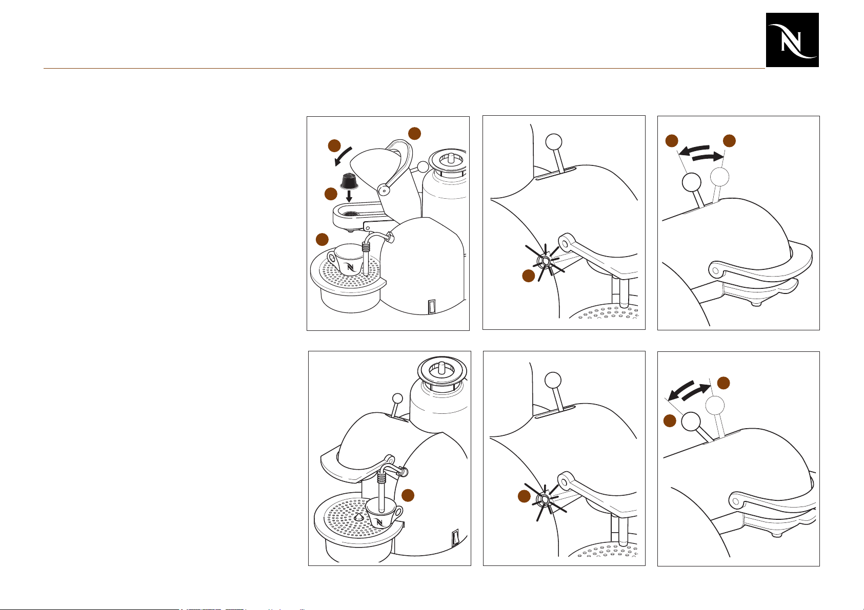
Making coffee
1 Open jaw
2 Insert capsule
3 Close jaw
4 Position cup
5 LED must be green
6 Place jaw stick in the front position,
coffee flows into the cup
7 Once the cup contains the required
amount, return the jaw stick to the
middle position
8 Briefly open jaw and eject capsule into
the capsule container
1
3
2
4
5
67
Preparing hot water
1 Position cup underneath steam pipe
2 LED illuminates green
3 Place jaw stick in the rear position, hot
water flows into the cup
4 Once the cup contains the required
amount, return the jaw stick to the
middle position
4
3
1
2
11
Page 12
Operation
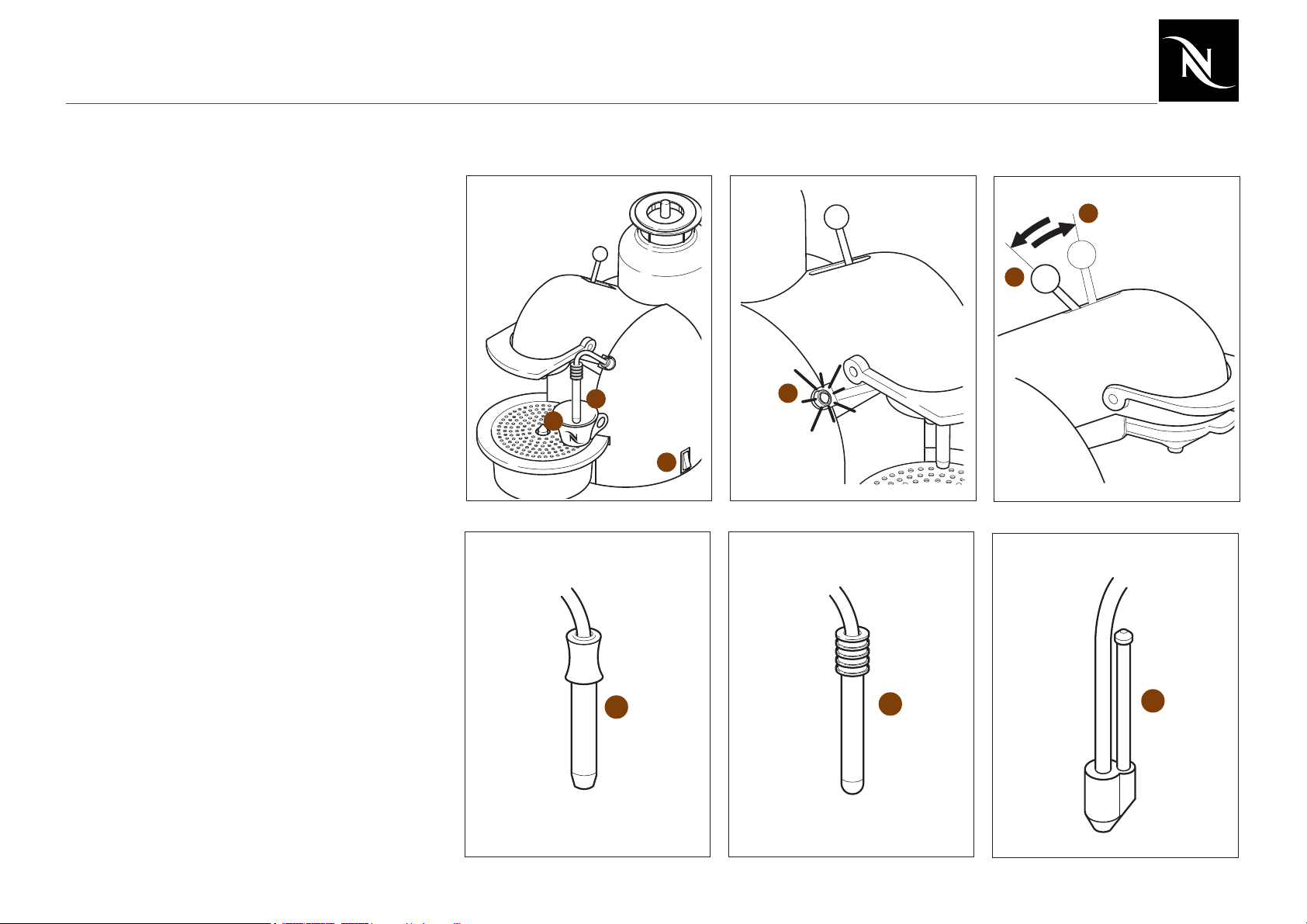
Heating with steam
1 Slide down frothing pipe (only frothing
aid A and B)
2 Press steam switch
3 LED flashes orange, wait until LED
illuminates orange
4 Immerse frothing pipe approx. 1cm
deep in the liquid
5 Place jaw stick in the rear position until
the required temperature is reached
6 Return jaw stick to the middle position
Frothing
6
5
1
4
3
1 Slide down frothing pipe (only frothing
aid A and B)
2 Press steam switch
3 LED flashes orange, wait until LED
illuminates orange
4 Immerse frothing pipe approx. 1cm
deep in the milk
5 Place jaw stick in the rear position until
the required foam is produced
6 Return jaw stick to the middle position
Frothing aids
There are three different types of frothing aid.
A) EF 749
B) EF 748 Turmix and Nespresso
C) EF 748 Krups
A
12
2
B
C
Page 13
Operation
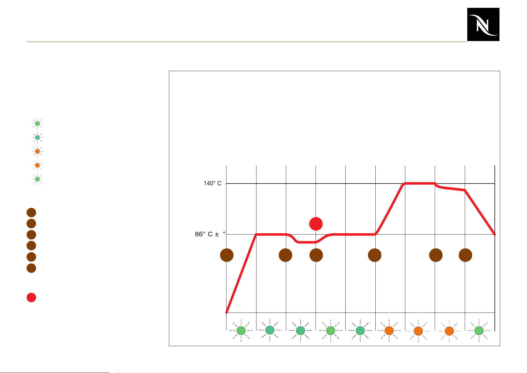
LED status diagram
The LED status diagram shows the
behaviour of the LED depending on
temperature and function.
LED-status
1 LED flashes green slowly
LED illuminates green
2
3 LED flashes orange slowly
4 LED illuminates orange
5 LED flashes green quickly
Operating sequence
A
Switch on main switch
B
Jaw stick forward or back
C
Jaw stick in middle
D
Operate steam switch
Jaw stick back
E
Jaw stick in middle
F
Note
After the preparation of coffee or hot
!
water, the green LED may flash
rapidly for a short time due to overtemperature.
Steam
preparation
Coffee and
hot water
preparation
Heating up
Ready
Coffee / hot water
preparation
Heating up
Ready
Heating up
Steam ready
Steam preparation
Cooling
!
3
A
1
2
CB E F
2
1
D
23
44
5
13
Page 14

Troubleshooting
Checking the machine - receipt (1)
The receipt check enables you to rapidly
locate faults on the machine and to initiate
appropriate repair action.
Keep to the order given in the table.
Repair any faults found and repeat the
repair routine to the end.
• Check appliance for visible damage
• Check mechanical elements
• Switch on
• Fill water tank
• Coffee preparation without capsule
- Parts of housing broken or damaged?
- Mains cable damaged?
- Has the customer opened the machine?
- Does the jaw stick engage?
- Does the closing handle work?
- Is the ejector mechanism in working order?
- LED flashes during heating up
- How long does the machine need for
heating up (typical time approx. 45s)?
- Water tank leaks?
- Does the reed contact work?
- Does the pump work?
- Does hot water escape?
• Hot water preparation
14
- Does the reed contact work?
- Does hot water escape?
Page 15
Troubleshooting
Checking the machine - receipt (2)
• Steam preparation
• De-scale
• Flow rate
• Check for leaks
• Temperature measurement
• Clean
- Does the steam switch work correctly?
LED must flash orange slowly during
heating up and then illuminate continuously.
- Does steam escape?
- See page 33
- See page 34
- See page 35 to 37
- See page 38
- See page 41
• Measure closing force
• Check reed contact
15
- See page 39
- See page 40
Page 16

Troubleshooting
Complaint:
Coffee temperature too low
Coffee temperature too high
No function
Cause?
• Jaw not preheated?
• Machine scaled (low outflow)?
• Faulty NTC temperature sensor?
• Faulty resistor in the thermoblock?
• Faulty heating PTC?
• Faulty NTC temperature sensor or
electronic mainboard?
• Machine not connected to mains?
Remedy!
- Preheat jaw, allow 2 large cups of water to
flow through without capsule
- De-scale machine (see page 33)
- Replace NTC (see page 22)
- Replace thermoblock (see page 22)
- Replace heating PTC (see page 30)
- Replace NTC temperature sensor (see
page 22)
- Replace electronic mainboard (see page 25)
- Check mains voltage and plug into mains
• Intermittent contact in cables?
• Faulty fine-wire fuse?
• Faulty main switch?
• Faulty NTC temperature sensor?
16
- Replace cable
- Replace - determine reason for fault (see
page 24)
- Replace main switch (see page 26)
- Replace NTC temperature sensor (see
page 22)
Page 17

Troubleshooting
Complaint:
No outflow
Cause?
• Water tank empty?
• Water tank fitted incorrectly?
• Top of brewing unit is clogged?
• Pyramid plate is clogged?
• Machine is scaled?
• Pump connected incorrectly, or faulty?
• Electronic mainboard fault?
Remedy!
- Fill
- Insert correctly
- Clean, de-scale or replace (see page 27
and 31)
- Replace (see page 31)
- De-scale (see page 33)
- Check pump connections
- Replace pump (see page 23)
- Replace electronic mainboard (see page 25)
17
Page 18

Troubleshooting
No steam function or too little steam
No capsule ejection
Cause?
• Steam and hot water pipe scaled?
• Steam and hot water pipe clogged?
• Steam switch faulty?
• Pump connected incorrectly?
• Reed contact faulty?
• Electronic mainboard faulty?
• Capsule ejector faulty?
• Capsule cage dirty or damaged?
Remedy!
- De-scale machine (see page 33)
- Clean pipe
- Replace steam switch (see page 26)
- Check electrical connections on pump (see
page 23)
- Check reed contact (see page 40)
- Replace reed contact (see page 29)
- Replace electronic mainboard (see page 25)
- Replace ejector (see page 31)
- Clean or replace capsule cage (see page 31)
Water on the jaw
Water runs out from the side of the jaw
Jaw does not close
• Pyramid plate dirty?
• Jaw poorly closed?
• Brewing unit leaks at the top?
• Not possible to close the jaw?
18
- Clean or replace (see page 31)
- Close jaw correctly
- Replace hose, seal or valve (see page 29)
- Screw capsule cage on fully
Page 19

Troubleshooting
Complaint:
Water on side of machine or below machine
Pump noisy
Cause?
• Thermoblock leaking?
• High pressure connections leaking?
• Silicon hoses torn?
• Valve on the water tank leaking?
• Internal manifold sleeve leaking?
• Water tank empty?
• Water tank not inserted correctly?
Remedy!
- Tighten connections on the thermoblock or
replace (see page 22)
- Replace seals or (and) hoses
- Check for leaks (see page 35)
- Replace silicone hoses
- Replace water tank
- Replace internal manifold sleeve
- Fill
- Insert correctly
Not enough froth when frothing milk
• Steam nozzle dirty or scaled?
• Frothing aid not correctly assembled?
• Milk not at fridge temperature?
• The temperature of the pot is too high?
• Heating element is scaled (temperature
loss)?
19
- Clean or de-scale (see page 33)
- Assemble correctly
- Only use milk at fridge temperature
- Use chrome-steel pot at fridge temperature
- De-scale machine (see page 33)
Page 20

Repair
General disassembly (stage 1)
Tools:
- Special screwdriver (oval)
General information:
The screws are labelled with letters (A, B and
C) in the figures.
These refer to the tightening torques for the
screws.
A = 0,5 to 0,9 Nm
B = 0,8 to 1,4 Nm
C = 1,3 to 1,8 Nm
A and B can be tightened by hand (A =
tighten lightly, B = tighten firmly).
For tightening screws labelled C it is imperative that a torque wrench is used.
Unplug from the mains before
disassembling machine appliance must be isolated!
Item no. 28087
Procedure:
1. Remove water tank, drip tray, and
capsule container.
2. Place machine on the disassembly jig
(item no. 28087).
3. Remove screws (13) on the underside
and rear of the side pieces.
4. Remove side pieces (2 and 3).
20
Page 21

Repair
General disassembly (stage 2)
Tools
- Torx screwdriver T10, T15
- Special screwdriver (oval)
Procedure
1. General disassembly stage 1.
2. Remove 3 bolts (13) on the cover at the
rear (9) on the underside.
3. Open jaw and remove screws (111) on
the cover.
4. Unscrew ball (80) on the jaw stick.
5. Remove screws (83) and closing lever
(84).
6. Move cover (81) a little to the side and
remove.
7. Remove 2 bolts (12) on the cover at the
rear on the top.
8. Remove cover at the rear (9).
21
Page 22

Repair
Replacing thermoblock
Tools / aids:
- Torx screwdriver T10, T15
- Flat nose pliers
- Open-ended spanner 8/10mm AF
- Pot to collect water
- Torque wrench
Procedure:
1. General disassembly stage 1 and 2 (see
page 20 and 21).
2. Remove bolt (47) on the thermoblock (66).
3. Remove all electrical connectors.
4. Remove fine-wire fuse clip (43).
5. Remove NTC temperature sensor (64).
Replacing NTC
Tools:
- Open-ended spanner 10mm AF
Procedure:
1. Remove connector on the logic board
2. Undo NTC temperature sensor (64)
replace
3. Assemble in reverse sequence. Only
tighten NTC temperature sensor lightly
until the spring washer is flat.
ATTENTION: Keep a pot at hand for
collecting the water left in the
thermoblock.
6. Remove water connections on the
thermoblock.
7. Replace thermoblock (66).
8. Assemble in reverse sequence. Only tighten
NTC temperature sensor lightly until the
spring washer is flat. Tighten bolt (46) to
torque C using torque wrench.
22
Page 23

Repair
Replacing pump
Tools / aids:
- Torx screwdriver T10
- Open-ended spanner 14mm AF
- Long-nose pliers
- Pot to collect water
Procedure:
1. General disassembly stage 1 (see page
20).
2. Remove all electrical connections
3. Remove steam switch (30, 63) on the
underside of the appliance to make it
easier to disassemble the pump (see page
25).
4. Remove clamp (45) and hose (65).
ATTENTION: Keep a pot at hand for
collecting the water left in the pump.
7. Remove seal (51) and angle (37).
8. Replace pump (61).
9. Insert seal (51) and tighten corner
connector (37).
10.Turn corner connector to the correct
position using open-ended spanner on
pump projection.
11.Remaining assembly in reverse sequence.
ATTENTION!
Check cable connection! If the
cables are reversed, it is not possible to
generate any steam.
Red cable
5. Remove angled hose (57).
6. Release pump first from bottom rubber
strap, then from the top rubber strap (54).
23
Page 24

Repair
Replacing fine-wire fuse
Tools:
- Torx screwdriver T15
- Long-nose pliers
- Torque wrench
Procedure:
1. General disassembly stage 1 and 2 (see
page 20 and 21).
2. Remove all connections with red cable.
3. Undo clamp (43).
4. Replace fault fine-wire fuse (998).
5. Assemble in reverse sequence. Tighten
bolt (46) to torque C using torque wrench.
24
Page 25

Repair
Replacing control board
Tools:
- Torx screwdriver T10
- Long-nose pliers
The service engineer must be
earthed using an earthing
strap!
Procedure:
1. General disassembly stage 1 (see page
20).
2. Place earthing strap around the wrist and
connect to the earthing cable on the unplugged machine! In this way a potential
difference is avoided.
3. Remove connections from the board.
4. Undo 2 screws (12) and remove the
control board.
5. Replace control board (59).
6. Assemble in reverse sequence (see wiring
diagram, p.32)
25
Page 26

Repair
Replacing main switch or steam switch
Tools:
- Torx screwdriver T10
- Long-nose pliers
Procedure:
1. General disassembly stage 1 (see page 20).
2. Remove screws (12) on underside of
appliance.
3. Remove connections
4. Replace main switch (62) or steam switch
(63).
5. Assemble in reverse sequence.
Replacing LED
Tools:
- Torx screwdriver T10
Procedure:
1. General disassembly stage 1 (see page 20).
2. Remove connector in the electronic
mainboard.
3. Remove screws (12) and cover (33).
4. Remove screw (48) on the LED board.
5. Replace LED board (58).
6. Assemble in reverse sequence.
Replacing steam pipe
Tools:
- Torx screwdriver T10
- Torque wrench
Procedure:
1. General disassembly stage 1 (see page 20).
2. Remove screws (12).
3. Remove cover (32).
4. Remove steam pipe (40) and replace.
5. Assemble in reverse sequence. Tighten
bolt (12) to torque C using torque wrench.
26
Page 27

Repair
Replacing jaw
Tools:
- Torx screwdriver T10, T15
- Cross-headed screwdriver
- Long-nose pliers
Procedure:
1. General disassembly stage 1 (see page 20).
2. Open jaw and remove screws (111) on the
cover.
3. Unscrew ball (80) on the jaw stick (134).
4. Remove screws (83) and closing lever
(84).
5. Move cover (81) a little to the side and
remove.
6. Disassemble hoses (85, 65) on the
ceramic valve and remove grounding wire
(115) on the support.
- Procedure on disassembly of the jaw when fitted.
7. Pull off hose (132) on the expansion
housing.
8. Unplug heating PTC (110) and reed
contact (86) on the control board.
9. Remove screws (131) on the support
module (126).
10. Remove complete jaw and replace.
27
Page 28

Repair
Complete jaw disassembly
Tools:
- Hammer (plastic head)
- Drift No. 4
- Torx screwdriver T10
- Torque wrench
Procedure:
1. General disassembly stage 1.
2. Disassemble jaw as per page 27.
3. Remove capsule cage (see page 31)
4. Remove cover (112).
5. Remove springs (98).
6. Remove shafts (108 +127).
- Procedure for complete disassembly of the jaw
7. Remove side closing lever (120), locking
lever (119) and shaft (113).
8. Remove screws on the control board.
9. Remove swivelling plate (97) with ejector
lever (94) and spring bearing (99).
28
Page 29

Repair
Complete jaw disassembly
Replacing reed contact
Perform points 1 to 9 (see page 28).
10.Remove screws (87).
11.Remove screws (96) and bearing (109).
12.Remove reed contact (86) and replace.
Attention!
The cover on the ceramic valve must
not be removed.
13.Assemble in reverse sequence.
Replacing connection to capsule cage
Perform points 1 to 9 (see page 28).
10.Remove screws (96) and bearing (109).
Replacing ceramic valve
Perform points 1 to 9 (see page 28).
10.Remove screws (96) and bearing (109).
11.Remove clamp (45) on the ceramic valve.
12.Remove connection (91) and hose (88).
13.Remove screws (87) on the ceramic valve.
14.Replace complete ceramic valve (incl.
reed contact, 86).
15.Assemble in reverse sequence. Fit new
seal (90) and tighten screws (87) to torque
C using torque wrench.
11.Remove clamp (45).
12.Replace connection (91) and fit new
seal (90).
13.Assemble in reverse sequence.
29
Page 30

Repair
Replacing heating PTC
Tools / aids:
- Torx screwdriver T10
Only pertains to machines
produced until sept. 2003.
Procedure:
1. General disassembly stage 1 and 2 (see
page 20 and 21).
2. Disassemble cover (112).
3. Remove connections on the electronic
mainboard.
4. Pull out cable.
5. Remove screws (96) and PTC clamp
(107).
6. Replace heating PTC (110).
7. Assemble in reverse sequence.
30
Page 31

Repair
Replacing pyramid plate
Refer to modification sheet
no. 2003-01.
Procedure:
1. Remove ejector (122).
2. Remove pyramid plate (123) with
receptacle (138).
3. Fit new pyramid plate with receptacle.
Ensure that the pyramid plate is inserted
in the correct position.
4. Fit ejector.
Replacing capsule cage
Tools / aids:
- Assembly tool (106)
Procedure:
1. Rotate capsule cage (137) from the cage
bracket using the assembly tool (106).
2. Fit new capsule cage.
31
Page 32

Repair
Electronic mainboard, wiring diagram
1) Reed contact
2) NTC temperature sensor
3) Board fastening
4) LED board
5) Steam switch (violet)
6) Steam switch (violet)
7) Pump (black)
8) Thermoblock (white)
9) Mains cable (blue)
10) Heating PTC (white)
11) Heating PTC (blue)
12) Fine-wire fuse and thermoblock (red)
1
2
4
3
5
6
3
7
9
8
10
11
12
32
Page 33

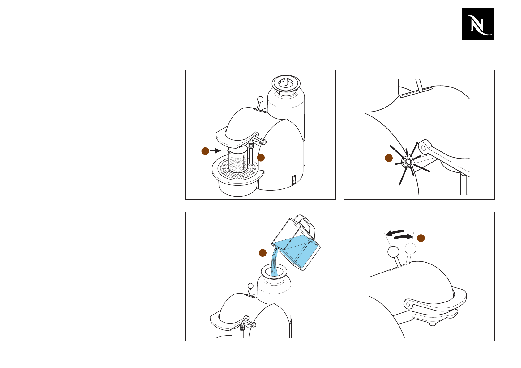
Maintenance
Descaling
Never use vinegar.
Decalcifier is aggressive to the
surface of the casing.
Preparation
1. Eject capsule, close jaw and place jaw
stick to middle position.
1
4
2. Remove steam nozzle and frothing pipe
and put them into a pot (min. 0.6 l capacity).
3. Remove drip grid and place pot on drip
tray.
Read safety instructions on side
of descaling sachet.
4. Fill water tank with 0.1 l descaling fluid
and 0.5 l water.
5. Switch on machine.
6. Wait till green indicator lights up.
Descaling
7. Place jaw stick in hot water position.
8. Let entire descaling solution pass through
steam pipe.
9. Place jaw stick to middle position.
2
3
Item no. 24361
9
7
10
6
8
10. Fill water tank again with descaling
solution from pot.
33
Page 34

Maintenance
Descaling
11. Place pot with steam nozzle and frothing
pipe on drip tray.
12. Place jaw stick in coffee position and let
pass the entire descaling solution through
coffee outlet.
13. Place jaw stick to middle position.
Rinsing
14. Empty pot. Rinse steam nozzle and
frothing pipe.
15. Flush water tank thoroughly and fill it with
fresh water.
16. Place pot on drip tray.
17. Place jaw stick in hot water position. Let
half a tank of water run through steam pipe.
18. Place jaw stick in coffee position and let
remaining water run through coffee outlet.
17
13
19
18
12
11
14
15
19. Place jaw stick to middle position.
20. Switch machine off – decalcification is
completed.
21. Mount steam nozzle and frothing pipe.
22. Insert drip grid.
23. Clean machine.
16
34
22
23
21
Page 35

Maintenance
Measuring rate of flow
1. Remove ejector
2. Remove pyramid plate support
3. Fit pressure gauge
4. Close jaw
5. Position measuring beaker underneath
6. Switch on machine
7. Open valve fully
8. Place jaw stick in the front position
9. Close valve until 12 bar are indicated
10. Perform measurement for approx.
30 sec.
11. There must be at least 60-120ml in the
measuring beaker
If the manometer indicates large
fluctuations during the
measurement (12 +/- 4 bar), this is an
indication that the pump is faulty.
Keep a watch for leaks!
12 bar
1
4
2
3
7
9
10
8
The manometer must be
observed continuously and the
pressure regulated using the valve if
necessary. With increasing temperature
the pressure also increases, if necessary
readjust the pressure to 12 bar.
60...120 ml
35
5
30 s
Page 36

Maintenance
Checking for leaks and pump pressure (1)
1) Preparation of the machine
1. General disassembly stage 1 (see
page 20).
2. Open jaw and remove screws (111) on
the cover.
84
83
134
3. Unscrew ball (80) on the jaw stick
(134).
4. Remove screws (83) and closing lever
(84).
5. Move cover (81) a little to the side and
remove.
6. Refit closing lever.
7. Fit pressure gauge.
8. Close jaw.
9. Position pot underneath.
81
111 (A)
36
Page 37

Maintenance
Checking for leaks and pump pressure (2)
The following components are checked for
leaks:
- Capsule cage
- Connections
- Thermoblock
- Pump
2) Check
1. Perform points 1 to 9 on page 35.
2. Jaw stick to the front (the valve on the
pressure gauge must be opened).
3. Switch on machine.
4. Leave water to run out for approx. 10 s.
5. Fully close valve. The pressure will
rise rapidly initially and stabilise
between 16-19 bar (pump pressure
check). The pressure will rise slowly
due to the temperature increase.
8. The needle on the display must not
drop below 12bar in 60 s.
9. Open valve, open jaw (pressure
gauge empties).
The residual pressure must be
released after the test by
opening the valve!
The pump is permitted to be in
operation for max. 50 sec.
without an outlet.
6. Visual and acoustic check on all
pressurised connections. The pump
must not be in operation for longer
than 50 s.
7. Switch off machine using the On-Off
switch (jaw stick remains in the front
position).
System: no leak leak
37
Page 38

Maintenance
Checking extraction chamber for leaks
1. Switch on machine.
2. Remove ejector.
3. Remove pyramid plate support.
4. Insert special pyramid plate support.
5. Insert capsule and close jaw.
6. Jaw stick to the front.
7. Check outflow. The coffee should flow out
evenly and without splashing to the side.
8. If the jet is not correct, replace capsule
cage.
Preparation of the special pyramid plate
support
Saw off the lower part of the pyramid plate
support such that the inner cone is not
damaged.
6
5
2
3
4
7
38
Page 39

Maintenance
Measuring coffee temperature
1. Switch on machine.
2. After warming up, leave 150ml of water to
flow through to heat the jaw.
3. Insert capsule (Cosi is the most suitable).
4. Close jaw.
5. Position a pot underneath.
6. Place jaw stick in front position.
7. Measure the temperature approx.
5 - 10 mm below the outlet opening.
8. Temperature should be approx.
86 °C ± 3 °C (187 °F ± 5.4 °F).
39
Page 40

Maintenance
Measuring closing force
1. Switch on machine
2. After warming up, leave 150ml of water to
flow through to heat up the jaw.
3. Insert capsule.
4. Attach spring balance to the middle of the
closing lever.
5. Press down closing lever with the aid of
the spring balance until the closing lever
is closed. Ensure that the spring action
of closing is not taken into account.
6. Read off value. Repeat measurement
several times as necessary.
Closing force for new appliance: 25N +/-5N
If the closing force is less than 10N,
replace capsule cage, pyramid plate and
support.
Art. Nr. 80005
Art. Nr. 4.004
Ordering information:
Spring balance (80005) and compression
force measuring tool (4.004) can be ordered
from the following address:
PESOLA AG
Rebmattli 19
CH-6340 Baar
Switzerland
Tel. +41 (0) 41 769 60 40
Fax +41 (0) 41 769 60 42
e-mail info@pesola.ch
www.pesola.ch
www.pesola.com
40
Page 41

Maintenance
Checking reed contact
1. Press the test button on the reed contact
tester - both LEDs must illuminate. If
necessary, replace battery.
2. General disassembly stage 1 (see page
20, only remove the side piece covering
electronic components).
3. Remove connection from reed contact to
the electronic mainboard and connect to
the reed contact tester.
4
5
4. Place the jaw stick at the front. The
“coffee” LED illuminates, otherwise the
reed contact is faulty.
5. Place the jaw stick at the rear: The
“steam” LED illuminates, otherwise the
reed contact is faulty.
During the test the machine
must be switched off and
unplugged from the mains!
3
1
41
Page 42

Maintenance
Daily maintenance and final cleaning
1. Clean water tank and fill with fresh water
2. Empty drip tray and clean
3. Empty capsule container
4. Flush jaw (min. 150 ml)
1
2
4
42
3
Page 43

Spare parts
Pos. EFR item Description
001 0025391 Support black
002A Side piece 748 right black
003A Side piece 748 left black
002B Side piece 748 right yellow
003B Side piece 748 left yellow
002C Side piece 748 right blue
003C Side piece 748 left blue
002D Side piece 749 right silver
003D Side piece 749 left silver
002E Side piece 749 right white
003E Side piece 749 left white
002F Side piece 749 right red
003F Side piece 749 left red
004A 0025394 Drip tray 748 black
004B 0026377 Drip tray 749 black
005 0025395 Capsule container black
006A 0025396 Cover 748
006B 0026378 Cover 749 black
007 0025427 Water tank cover black
008A 0027295 Float yellow
008B 0027120 Moulded plug black
009 0025404 Cover rear black
010 0026373 Centring ring water tank black
43
Page 44

Spare parts
Pos. EFR item Description
011 0023908 Valve flange 420 black to water tank
012 0016052 Cross panhead screw KST/PT 3.0x12 zinc plated blue Torx-10
013 0024863 Cross panhead screw locking washer zinc plated blue oval
KST/Remf.3.0x12
014 0010585 Locking washer 770 Inox
015 0010586 Grid 770 rust-free
016A 0025446 Drip plate 748
016B 0026374 Drip plate 749
017 0011933 IInternal manifold sleeve (M3) 22.22/15.87x4.76 black
018 0015890 Elastic stop 15.9 x 4.75mm black SJ-6115
019 0025463 Water tank transp. compl. welded/assembled
020 0025451 Base plate
44
Page 45

Spare parts
Pos. EFR item Description
030 0025417 Switch panel black
031 0025409 Receptacle steam pipe black
032 0025419 Panel steam pipe black
033 0025418 Panel LED black
035 0027429 Expansion housing cpl. welded, bare
036 0006517 Cap top D=16x10.6mm for heater cartridge
037 0005466 Connection angle black 770 (pump)
038 0001053 Strain relief transparent screwed
039 0001442 Sheet bracket 946 EX100/964
040 0025751 Steam pipe long, chrome-plated
041A 0001349 Steam nozzle 925 Ms chrome-plated M6x0.5 for screw fitting
041B 0012050 Protective rubber Turmix Nespresso
042A 0011970 Frothing aid Turmix Nespresso
042B 0002630 Frothing aid Krups 72mm compl. incl. brass pipe, body, cap
042C 0014622 Frothing aid 749 AE compl. with grill AE Ks nozzle, pipe, O-ring
043 0021542 Fine-wire fuse TB2001 0.5x10.0x21.0mm
044 0005245 Lock washer M5 zinc-plated blue
045 0005470 Clamp 770 pressure hose
046 0019799 Screw GF/Tapt.M4.0x 8 zinc plated panhead with lock ring Torx-20
047 0018121 Screw GF/Tapt.M4.0x40 zinc plated blue panhead Torx-20 waxed
048 0020151 Screw sheet 2.9x 9.5 zinc-plate black panhead Torx-10 point
049 0025452 Support TB2001
050 0008242 Washer 04.3x12.0x1.5 zinc plated blue M4
45
Page 46

Spare parts
Pos. EFR item Description
051 0024374 O-ring 003.40x1.90 silicone 70 Shore red, 2-comp. silicon
052 0001565 O-ring 005,28x1.78 EPDM 70 Shore black
053 0010629 O-ring 005.70x1.90 EPDM 70 Shore black
054 0025450 Pump supports AE grey 60 Shore 3 fastening holes 6.5mm
055 0009212 Hose silicon 05.0x2.00x090 75 Shore, transparent
056 0012440 Hose silicon 08.0x1.75x260 55 Shore white, cut
057 0005454 Angle hose 770 silicon
058 0025298 El.LED 748
059 0025299 El. control board 748 230-240V 50-60Hz
060A 0025449 Mains cable black HO5VVF-3G075 1,50 S1: Cebec S2: 140/90/40
060B 0025554 Mains cable black H05VVF-3G075 1.50 S1:GB S2:140/90/40
060C 0025555 Mains cable black H05VVF-3G075 1.50m S1: SEV/ S2: 140/90/40
061 0018526 Pump CP4/SP(CP2) 230V/50Hz without thermost./
without strap/with th. recept.
062 0004561 Switch B111C1121000 16A/250V black, making 0/I white
063 0025447 Switch B1A4C112K000 16A/250 black white
marking steam symbol
064 0015448 Temperature sensor with wires 230mm
065 0027345 Hose PFA D4.0/2.50x280mm
with 1 clamping ring/1 Sertokl’ ring/2 tubular rivets assembled
066 0026677 Replacement thermobl.2001 230V compl. with Serto fitting
and flange connector
46
Page 47

Spare parts
Pos. EFR item Description
080 0024394 Ball handle black for jaw stick
081A 0027886 Cover 748 silver painted symbols black
081B 0025401 Cover 749 black symbols silver
081C 0027884 Cover 748 yellow symbols black
081D 0027885 Cover 748 blue symbols black
082 0025432 Panel valve lever Inox
083 0024537 Cross cyl. head screw KST/PT 4.0x 8 Inox Torx-15
084 0025293 Closing lever chrome-plated cast zinc
085 0025278 Hose FEP D4.0/2.50x220mm with 2 clamping rings
with tubular rivets assembled
086 0024397 El. reed contact board
087 0022504 Screw KST/PT 3.5x16 zinc-plated blue panhead Torx-10
088 0025280 Hose FEP D4.0/2.50x 35mm
089 0024314 Support ring black profile seal
090 0024379 Seal black for capsule cage connection
091 0024301 Connection to capsule cage black
093 0005255 Washer 03.2x09.0x0.8 zinc-plated blue M3 DIN 9021/ISO 7093
094A 0024296 Ejector lever black first version
094B 0028218 Ejector lever 748/2 black
095 0027339 Spring (torsion spring) Inox D=1.0x12.0;Nt4.25
096 0020740 Cross panhead screw GF/Tapt.M3.0x 8 Torx-10, waxed
zinc-plated blue
097 0024288 Swivelling plate Inox to brewing unit
098 0024377 Spring for brewing unit D=0.70x6.0x29.4mm Inox
099 0024304 Spring bearing plain
102 0024387 O-ring 010.00x2.00 black
104 0024317 Plate Inox
105 0024318 Banjo bolt Inox
106 0024361 Assembly tool black for capsule cage
107 0024307 PTC clamp until Sept. 2003 only
47
Page 48

Spare parts
Pos. EFR item Description
108 0024298 Shaft for module support rear, Inox hardened
109 0024302 Bearing capsule cage aluminium
110 0024396 Heating PTC type 83/112/20/17,5 32-I, for brewing unit 748
111 0018904 Cross panhead screw KST/PT 3.0x16 zinc plated blue Torx-10
112 0024360 Cover swivelling piece black
113 0024300 Shaft for closing lever steel hardened
115 0025455 Si wire EU yellow-gr.480mm 0.75 1xFHL4.8- Ni/1xRKS4.3-Ni
116 0010997 Panhead screw M4.0x 8 zinc-plated black Torx-15
117 0024390 Connecting piece black for closing lever
118 0024388 Recessed disc size 6, for shafts / with slot, type KL, dacrometised
119 0024395 Closing lever plate Inox
120 0024291 Sealing plate Inox
121 0024295 Shaft sealing system for brewing unit Inox hardened
122 0024311 Ejector black
123 0036692 Plate pyramide Polymer black PPP
124A 0025676 Outlet compl. welded for brewing unit, black first version
124B 0029385 Outlet 748/2 compl. welding black
125 0011020 Seal black (OCS) for outlet
126A 0024312 Support module, black first version
126B 0028220 Support 748/2 module, black Brewing unit
127 0024299 Shaft for module support steel hardened
128 0024297 Supporting plate Inox
129 0025678 Cover spring
130 0025398 Panel brewing head black
131 0019504 Cross panhead screw KST/PT 3.0x20 zinc-plate blue Torx-10
132 0025287 Hose silicon 05.0x2.00x200 70 Shore black, cut
133 0026392 Hose silicon 08.0x1.75x190 55 Shore white, cut
48
Page 49

Spare parts
135 0026650 Replacement ceramic valve pre-assembled
Pos. EFR item Description
136 0026797 Replacement support ring with seal fitted
137 0026651 Replacement capsule cage fitted
138A 0026799 Replacement outlet with seal fitted first version
138B 0037590 Spare-Outlet 737 compl. with gasket assemb.
139 0026798 Replacement brewing unit without support assembled
140 0026801 Replacement brewing unit with support assembled
998A 0025461 EF wire EU 216°C (1xG4) brown 130/120/120/250mm
998B 0025456 Si wire EU black 310mm 0.75 1xFHL4.8- Ni/1xFLH6.3-Ni
998C 0025460 Si wire EU violet 260mm 0.75 1xFHL4.8-Ni/1xFHW4.8-Sn
49
Page 50

Spare parts
0027918
0028087
0027917
0024361
998D 0001219 Si wire EU white 130mm 0.75 2xFHL4.8-Ni
Pos. EFR item Pesola item Description
0027917 Pressure gauge
0027918 Reed contact tester
0028087 Machine assembly/disassembly
0024361 Assembly tool
0004872 Special (oval) screwdriver with Bit
0004878 Bit oval for screwdriver
80005 Spring balance 5kg. Pesola AG, Switzerland
4.004 Spring balance accessory
(compression force measuring tool) Pesola AG, Switzerland
80005
4.004
0004878
0004872
50
 Loading...