

Page 1
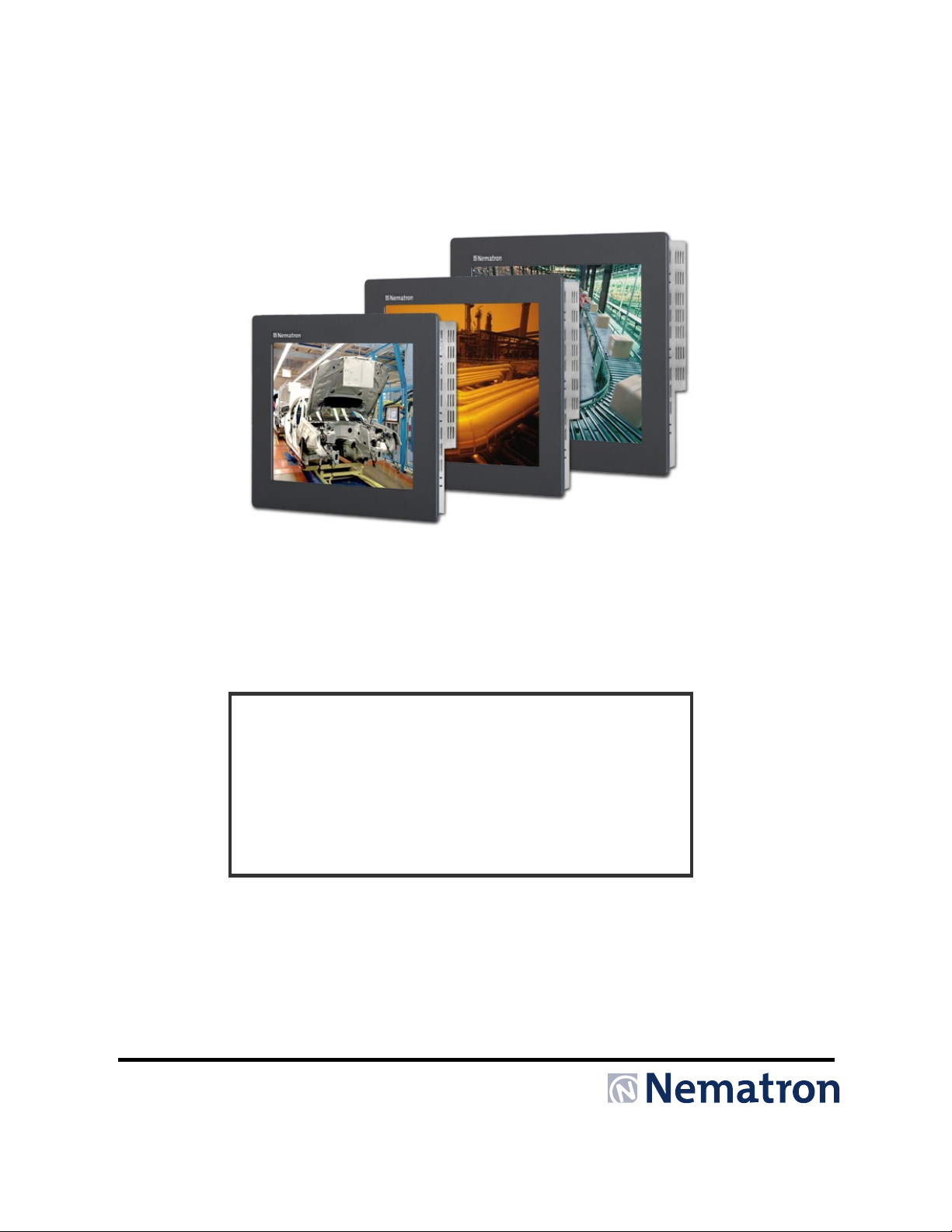
M-Series
Document No. DOC-MON-018,
M-Series User Manual, Rev H Rel. 9-2012
Industrial Flat Panel Monitor
User’s Guide
Page 2
2
Revision Number
Description of Change
Release Date
B
Added Windows Vista driver to list of supported drivers, Added
4-2007
C
Added DVI functionality, UL Hazardous Locations Notes and
6-2008
E
Revision for Field Wiring Requirements
5-2010
F
Combined all monitors into one, Added –EN options and M1200
9-2010
H
UL Required changes for UL 1604 to ANSI/ISA 12.12.01-2012
9-2012
Nematron reserves the right to make changes in specifications described herein at any time without
responsibility for damage caused by misuse or improper use of its products.
Revision List
A Initial Release 9-2006
notes to driver list, Changed Logo, Corrected H X W Reversals on
page 5
Warnings
D Replaced “Power” with “Display Power” on button description,
added IEC 60950-1& RoHS to Agency Approvals, Added Input
Source Select instructions, Changed input power to 25 Watts and
updated display specifications.
G Added M2200WT 12-2011
Conversion
8-2008
notice in order to improve design and r eliability. Nematron do es not assume any respons ibility for
the use of any circuitry de scribed; no circuit patent licenses ar e implied. Nematron assumes no
WARRANTY
Nematron warrants to Customer that the Products will be free from defects in material and
workmanship under norm al use and service for a period of two years from date of invoice. Custom er’s
exclusive remed y for breac h of this war rant y is th at Nematron will either (i) r epair or re place , at its o ption,
any Product which fails dur ing the warranty period because of s uch def ect (if Cus tom er prom ptly reported
the failure to Nematron in writing) or, (ii) if Nematron is unabl e to repair or rep lace, Nematron will refund
the purchase price of the Product upon its return to Nematron. This warranty does not apply to any
Product which has b een s ubj ected t o m isuse, ab norm al ser vice or han dling, or which has bee n altere d or
modified in design or construction, or which has been serviced by anyone other than Nematron. The
warranty set forth herein is in lieu of, and exclusive of, all other warranties, express or implied.
Document No. DOC-MON-018, M-Series User Manual, Rev H Rel. 9-2012
Page 3

3
Chapter 1 - Introduction
The M-Series are high performance TFT flat panel monitors specifically designed for harsh
industrial environments including Class I & II, Division 2 Hazardous Locations. The monitors accept
standard analog VGA or Digital DVI inputs. They can display VESA video m odes up to 1680 x 10 50 at
75Hz with 16 million color s. An optional 5-w ire analog touch scr een is available that offers both RS -232
and USB interface cap ability. The m onitor is housed in a heavy dut y steel chassis with a powder coate d
machined aluminum bezel. The monitor is c ertified to NEM A 4/4X/12 standar ds, is UL/CUL list ed, meets
CE requirements and is RoHS com pliant. Panel mounting is sim plified using convenient mount ing clips
instead of conventional studs. Options include: a 5-wire analog resistive touch screen or clear Lexan
window, a 304 stainless steel bezel, rack mount bezel (M1900 only), enclosed versions (M1500 and
M1900 only), and 24 volt DC in put power supply (not available on the enclosed o ptions). A ll monitors are
shipped with a power input wiring receptacle, VGA cable, touch screen cable (if equipped), mounting
hardware, manual and driver software.
Features
• UL 508 and ANSI/ISA 12.1 2.01-2012 listed for Hazardous Locations: Class I, Division 2, Groups
A, B, C, D and Class II, Division 2, Groups F and G, Class III hazardous locations when mounted
in a NEMA Type 1, 4, 4x, or 12 enclosure (does not include –EN options, -EN units only have UL
508 approvals only)
• NEMA 4/4X/12 front bezel (does not include –EN or –RM options)
• 2-Year warranty
• RoHS Compliant
• Integral 100 -240 VAC power supply
• Simplified installation with no studs
• Thin design – Only 2.7” behind bezel
• Accepts Analog Video or Digital Video (DVI) inputs
• VESA compliant – all modes up to WSXGA+, 75Hz
• Optional 5-wire resistive touch screen with both RS-232 and USB interface
• Optional 304 stainless steel front bezel
• Optional 24 VDC input power
• Optional Rack Mount front bezel on the M1900 (19”)
• Optional Rear NEMA 1 Enclosure (-EN)
Page 4
4
Mode
640 x 350 @ 70Hz
720 x 400 @ 70Hz
640 x 480 @ 60Hz
640 x 480 @ 72Hz
800 x 600 @ 56HZ
800 x 600 @ 60Hz
800 x 600 @ 72Hz
1024 x 768 @ 60Hz
1024 x 768 @ 70Hz
1024 x 768 @ 75Hz
1280 x 1024 @ 75Hz
1600 x 1050 @ 75Hz
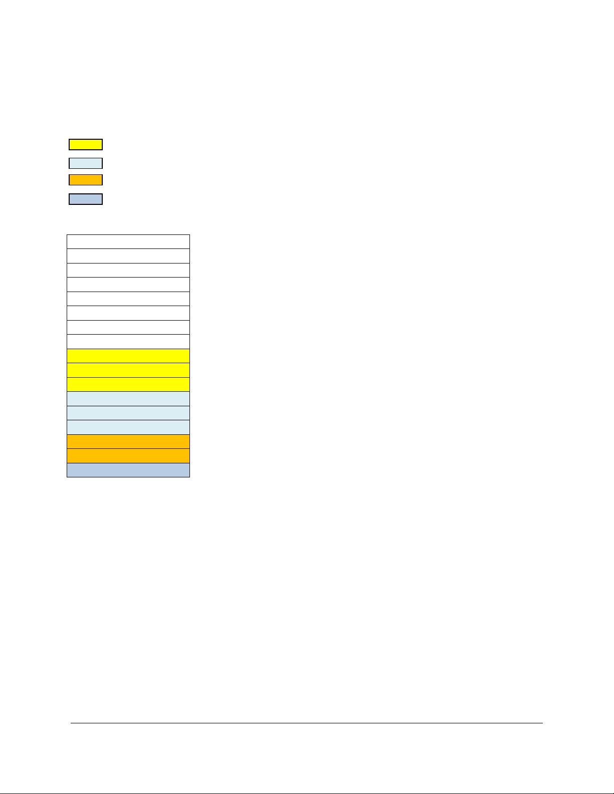
Supported PC Video Modes
The M-Series monitors support the following video modes:
Note: The highlighted PC display modes produce the best image quality on the size monitors as follows:
- M1200
- M1500
- M1700 & M1900
- M220W
640 x 400 @ 70Hz
640 x 480 @ 75Hz
800 x 600 @ 75Hz
1280 x1024 @ 60Hz
Page 5
5
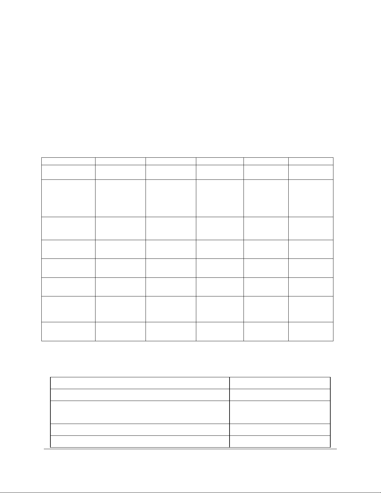
Specifications
M1200
M1500
M1700
M1900
M2200W
Front Panels
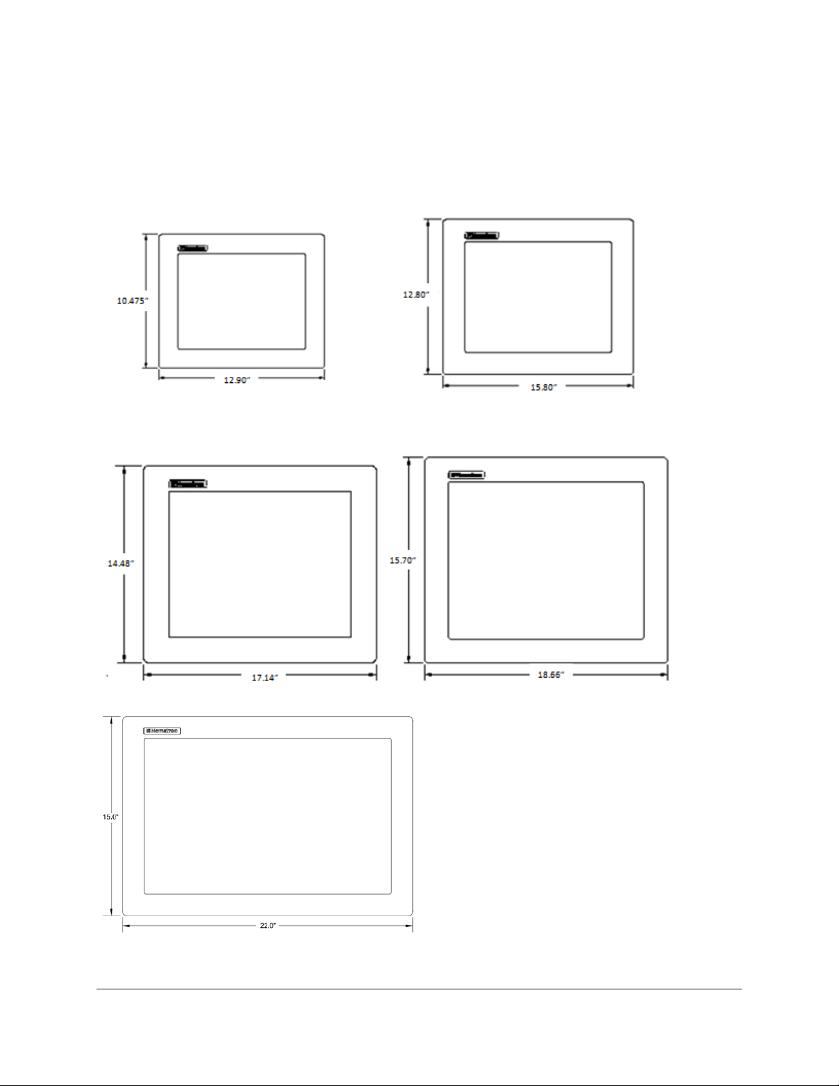
The M-Series monitors have NEMA 4/4X/12 sealed f ront panels when m ounted in an appropr iate
NEMA rated enclosure. See Chapter 2 for more details on installation and selection of an appropriate
enclosure. All five sizes have very similar front panels with different dimensions.
Figure 1.0: M-Series Front Panel Comparison
Page 6
6
The standard front p anels are p owder coated aluminum . The optiona l Stainless Steel front pa nel is t ype
M1200
M1500
M1700
M1900
M2200W
12.1”
(307.34mm)
15.0”
(381.0mm)
17.0”
(431.8mm)
19.0”
(482.6mm)
22.0”
(558.8mm)
304 and will not contain a logo pock et or logo on the f ront. T he window area is c lear pol ycarbo nate when
ordered without a to uchscreen. The touchsc reen option is chemicall y strengthened glass cover ed by a
polyester overlay. The polyester overlay has better resistance to chemicals than the polycarbonate
window. Depending on the chemicals involved in your application consideration should be given to
choosing the proper win dow m aterial. In add ition ther e is a Rack Mount front p anel opt ion for the M19 00
(19” unit) only. This f ront panel is powder coated alu minum and is 9U high wit h four rack mount s paced
counter-bored mounting holes on each side of the panel. This panel is not NEMA sealed when installed.
DISPLAY
Display Diagonal
Display Size
(Active Area
HxV)
Native
Resolution
Displayable
Colors
Brightness,
Typical
Contrast Ratio,
Typical
Horizon/Vertical
View Angle,
CR>5, Typical
Backlight Life,
Typical
TOUCH SCREEN (Optional)
Touch Screen Technology 5- Wire Analog Resistive
9.69” x 7.26”
(246.0mm x
184.5mm)
SVGA,
800 x 600
262K 16M 16M 16M 16M
400 Nit 300 Nit 380 Nit 300 Nit 300 Nit
500:1 800:1 1000:1 2000:1 1000:1
130°/110° 150°/145° 170°/170° 178°/178° 178°/178°
50,000 hrs 50,000 hrs 50,000 hrs 50,000 hrs 50,000 hrs
11.97” x 8.98”
(304.0mm x
228.1mm)
XGA,
1024 x 768
13.30” x
10.64”
(337.8mm x
270.3mm)
SXGA,
1280 x 1024
14.82” x
11.85”
(376.4mm x
301.0mm)
SXGA,
1280 x 1024
(360.68mm x
18.65” x
11.65”
538.48mm)
WSXGA+
1680 x 1050
Interface RS-232 or USB
Positional Accuracy (Maximum Error) 0.18” (0.19” M1900)
4.57mm (4.83mm M1900)
Positional Accuracy (Standard Deviation of Error) < 0.08” (< 2.0 mm)
Expected Life >35,000,000 Activations
Page 7
7
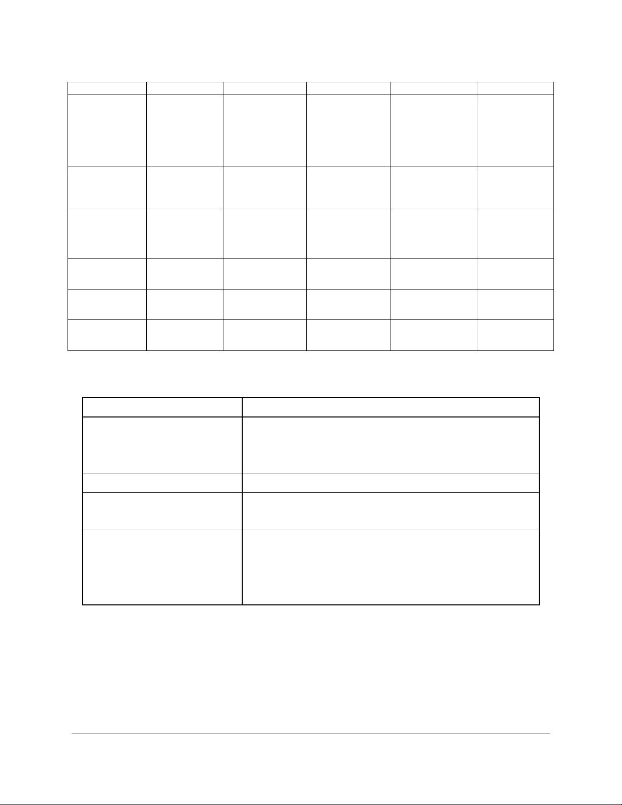
PHYSICAL
M1200
M1500
M1700
M1900
M2200W
10.475” x
Over All
Dimensions
(H x W x D)
Panel
Mounting
Depth
Cutout
Dimensions
(H x W)
Weight
Shipping
Weight
Option Weight
(-SS)
ELECTRICAL
AC Input Voltage 100 – 240 VAC, 50/60 Hz
12.9” x 2.65”
(266.1mm x
327.2mm x
67.3mm)
2.4”
(61.0mm)
9.68” x 12.10”
(245.9mm x
307.3mm)
9.5 lbs
(4.31kg)
14.0 lbs
(5.89kg)
+2.5 lbs
(1.13kg)
12.80” x 15.80”
x 2.65”
(325.1mm x
401.3mm x
67.3mm)
2.4”
(61.0mm)
12.00” x 15.00”
(305mm x
381mm)
14.0 lbs
(6.35kg)
19.0 lbs
(8.62kg)
+3.5 lbs
(1.58kg)
14.48” x 17.14”
x 2.85”
(367.8mm x
442.0mm x
72.4mm)
2.6”
(66.0mm)
13.70” x 16.35”
(348mm x
415.3mm)
18.5 lbs
(8.39kg)
23.5 lbs
(10.66kg)
+3.75 lbs
(1.70kg)
15.70” x 18.66”
(398.8mm x
474.0mm x
75.0mm)
(68.6mm)
14.90” x 17.75”
(378.5mm x
450.9mm)
(10.21kg)
(12.47kg)
+4.0 lbs (1.81kg) N/A
x 2.95”
2.7”
22.5 lbs
27.5 lbs
15.00” x 22.0”
x 2.95
(381mm x
558.8mm x
75.0mm)
2.7”
(68.6mm)
14.2” x 21.2”
9360.68mm x
538.48mm)
23.0 lbs
(10.43kg)
30.0 lbs
(13.60kg)
AC Input Current M1200 & M1500 – 0.5 A Maximum
M1700 & M1900 - 1.0 A M aximum
M2200W – 1.0 A Maximum
DC Input Voltage (Optional) 18 – 36 VDC
DC Input Current (Optional) M1200, M1500, M1700, & M1900 -2.0 A Max
M2200W – 4.5 A Max
Input Power M1200/M1500 - 25 W Typical*
M1700 – 30 W Typical*
M1900 – 35 W Typical*
M2200W – 60 W Typical*
* Typical Power is m easured witho ut an y add itional I/O or exp ansi on opt ions. An y addit ional I/ O ins talled
during application can increase this value.
Page 8
8
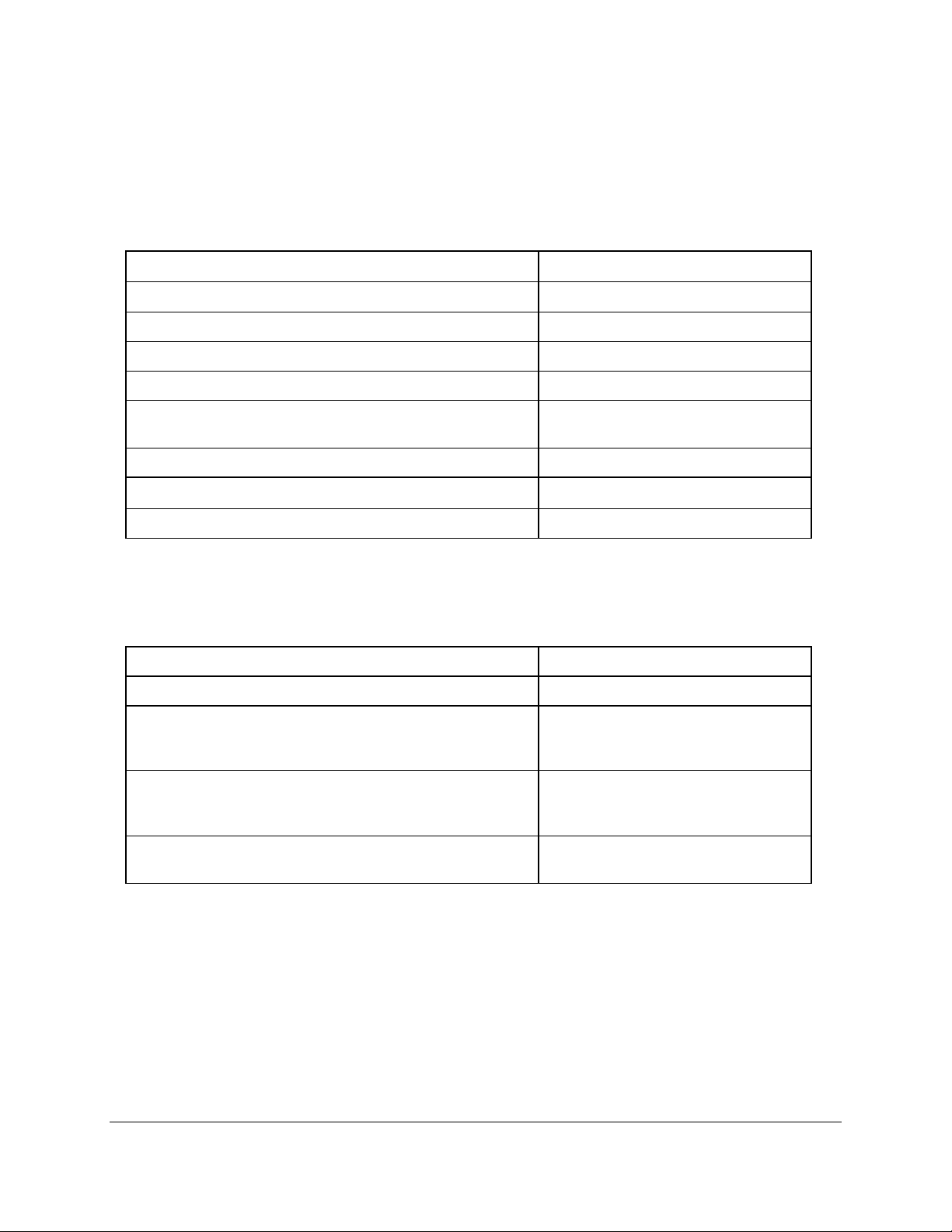
CE, EN 55022: Class A,
2: Class A,
2,
ENVIROMENTAL
Operating Temperature
0°C to 50°C
Non-Operating Temperature
Operating & Non-Operating Humidity 20% to 80% RH, non-condensing
Operating Shock* 15g peak acceleration, 11msec
Non-Operating Shock 30g peak acceleration 11msec
Operating Vibration (5-2000 Hz) 1 0.006” peak to peak displacement,
Non-Operating Vibration (5-2000 Hz) 1
Operating Altitude 2 Sea level – 10,000 feet
Non-Operating Altitude 2 Sea level – 40,000 feet
1 Shock and Vibration specifications are established using Solid State drives and non-rotating media.
2 Altitude Specification is established by using all internal component specifications.
AGENCY
Front Panel NEMA Rating NEMA 4/4X/12, IP65
FCC 47 CFR, Part 15, Class A
EU CE Marking Compliance
EN 61000-3-3, EN 61000-6-
-20°C to 60°C
1g maximum acceleration
EN 61000-3-
Safety Agency Approvals (panel mount versions only) UL 508 Listed, ANSI/ISA 12.12.01-
2012 Listed*, cUL Listed CSA C22.2,
#142, CSA C22.2, #143*
Safety Agency Approvals (enclosed versions only) UL 508 Listed, cUL Listed CSA
C22.2
* See appropriate note below for the applicable unit or option being utilized.
Page 9
9
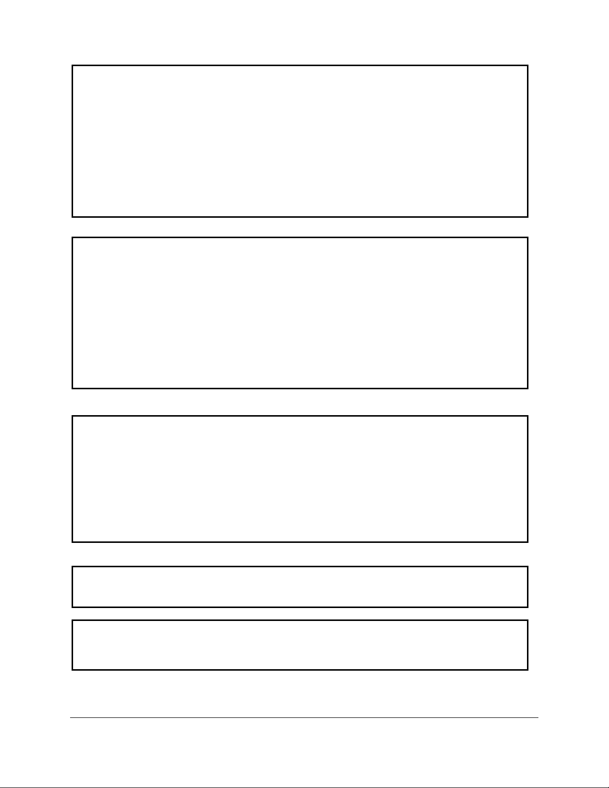
WARNING – EXPLOSION HAZARD – DO NOT DISCONNECT EQUIPMENT
OF IGNITABLE CONCENTRATIONS.
NOTE (RACK MOUNT VERSIONS):
UNT INSTALLATION ON A TYPE 1 ENCLOSURE WITH
NOTE: (ENCLOSED M-SERIES VERSIONS):
WARNING – EXPLOSION HAZARD – SUBSTITUTION OF ANY COMPONENTS
NOTE (PANEL MOUNT VERSIONS):
SUITABLE FOR USE IN CLASS I, DIVISION 2, GROUPS A, B, C AND D, CLASS
II DIVISION 2, GROUPS F AND G, CLASS III HAZARDOUS LOCATIONS, OR
NONHAZARDOUS LOCATIONS ONLY
FOR USE ON A FLAT SURFACE OF A TYPE 1, 4, 4X, OR 12 ENCLOSURE
WITH PROVISIONS FOR CLASS I DIVISION 2 WIRING METHODS
TEMPERATURE CODE: T5
SUITABLE FOR USE IN CLASS I, DIVISION 2, GROUPS A, B, C AND D, CLASS
II DIVISION 2, GROUPS F AND G, CLASS III HAZARDOUS LOCATIONS, OR
NONHAZARDOUS LOCATIONS ONLY
FOR RACK MO
PROVISIONS FOR CLASS I DIVISION 2 WIRING METHODS
TEMPERATURE CODE: T5
A LISTED VESA STYLE MOUNT SUITABLE W ITH A MINIMUM LOAD RATING
OF 35 POUNDS SHALL BE USED IN THE END INSTALLATION
FOR USE IN NONHAZARDOUS LOCATIO NS ONLY
TYPE 1 ENCLOSURE
MAY IMPAIR SUITABILITY FOR CLASS I, DIVISION 2
WHILE THE CIRCUIT IS LIVE OR UNLESS THE AREA IS KNOW TO BE FREE
Page 10
10
M1200
M1500
M1700
M1900
M2200WT
WARNING – EXPLOSION HAZARD – DO NOT DISCONNECT THE USB PORTS
UNLESS THE POWER HAS BEEN SWITCHED OFF AND THE AREA IS KNOWN
TO BE NON-HAZARDOUS
Chapter 2 - Installation of Computer
Panel Mount M-Series Unit installation
The panel m ount versions of the M-Series are intended to be m ounted in an d used where NEM A
1, NEMA 4/4x and NEM A 12 type enclosures are emplo yed. Enclosures made of heavier gaug e metal
work better because they won’t deform or bend as easily when the monitor’s sealing gasket is
compressed. The monitor meets NEMA 4/12 sealing specifications when properly installed in an
approved NEMA enc losure constructed from 14-gaug e or hea vier ste el. T he com puter uses “U”-shaped
clips and a special gasket to achieve the proper seal.
When selecting an enclos u re r em em ber to allo w ad eq uate s pace ar oun d t h e r ear of the computer
for good air flow. Do not bl oc k air flow from below or a bov e th e monitor. If possibl e mount the computer in
a vertical orientation. T he unit is designed t o work in env ironments up to 5 0 degrees Centigra de ambient
temperature inside the enc losure. Remember to account for heat diss ipated from other equipment that
may be installed inside the same enclosure.
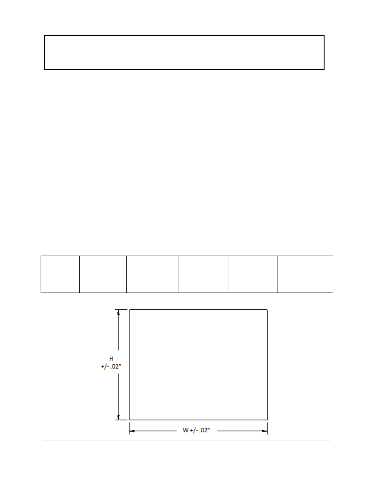
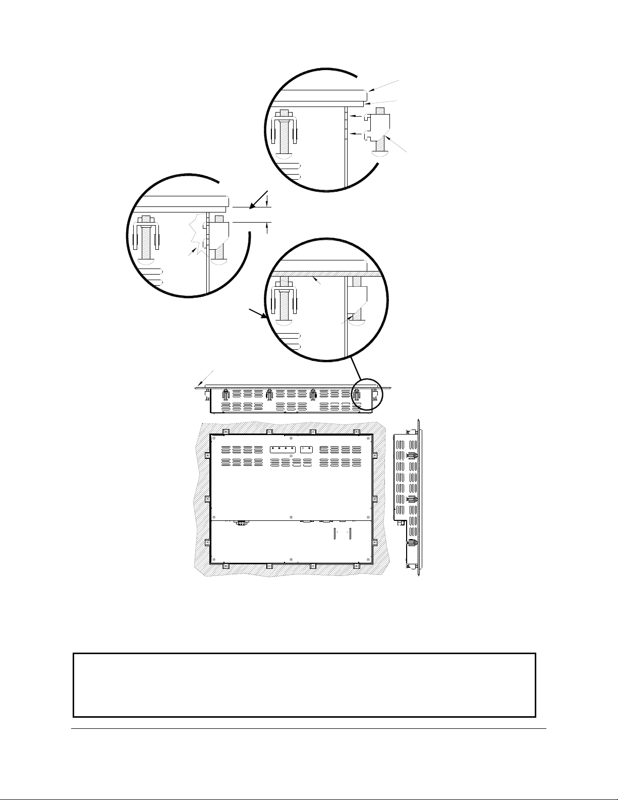
To install the computer , make a cutout accordin g to the diagrams below in one of the walls of
your NEMA enclosure. N ex t hold the u nit in p lace w hile you install t he m ounting clips. T ighten the c lips
to the point where the back of the unit’s front bezel just begins to contact the front of the NEMA
enclosure. The use of an adjustabl e torque driver is recomm ended. The screws s hould b e tightened to 8
inch-pounds. Tighten the clips in a cross pattern. This will help to develop an even pressure on the
sealing gasket. DO NOT OVER TIGHT EN AS DAMAGE CAN RESULT IN THE COM PUTER CAUSING
LOSS OF SEALING INTEGRITY.
Cutout
Dimensions
(H x W)
9.68” x 12.10”
(245.9mm x
307.3mm)
12.00” x 15.00”
(305mm x
381mm)
13.70” x 16.35”
(348mm x
415.3mm)
14.90” x 17.75”
(378.5mm x
450.9mm)
14.20” x 21.2”
(473.8mm x
296.1mm)
Page 11
11
UPMENU DOWNSELECT POWER
FRONT PANEL
OF NEMA
ENCLOSURE
TIGHTEN TO 8
INCH-POUNDS
COMPRESSABLE NEMA
SEALING GASKET
.25" THICK MONITOR
FRONT BEZEL
MAXIMUN ALLOWABLE
PANEL THICKNESS
CUT AWAY
.325"
FRONT PANEL OF
NEMA ENCLOSURE
MOUNTING CLIP
WITH 10x32 SCREW
Mounting Clip Installation
NOTE: WHEN INSTALLING THE MOUNTING CLIPS TIGHTEN THE SCREWS
BREAKAGE.
REAR VIEW OF PANEL
MOUNTED M-SERIES MONITOR
TO 8-10 INCH-POUNDS MAXIMUM. OVERTIGHTENING THE SCREWS WILL
RESULT IN A COMPRIMISED NEMA SEAL AND MAY CAUSE TOUCH SCREEN
Page 12
12
Rack Mount Unit Installation
The M1900 with a rack mount front panel is intended to be mounted to a 19.0” wid e rack in a
NEMA Type 1 or better enclos ure. The unit can be m ounted using standard rack mount hardware ( not
supplied) via the eight (4 each side) counter-bored holes in the front of the panel. The front panel is
intended to be mounted in a vert ic al height of 9 U (16.0”) on t he rac k. This unit is not NEM A s ealed when
mounted like the panel mount versions.
When selecting an enclosure remember to allow adequate space around the rear side of the
computer for good air flo w. The unit is designed to work in environm ents up to 50 degrees Centigrad e
ambient temperature inside the enclosure. Remember to account for heat dissipated from other
equipment that may be installed inside the same enclosure.
Enclosed Unit Installation
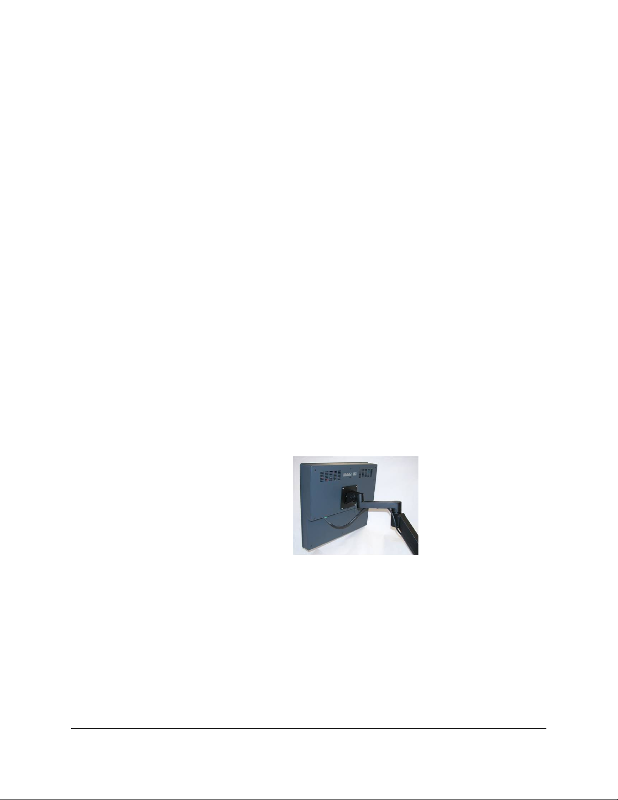
The enclosed M-Series products ar e intended t o be stand-a lone NEMA T ype 1 units. T hese are
required to be mounted to a VESA style mount with a minimum load rating of 35 pounds. A desktop
stand, wall mount, or articulat ing arms are examples of VESA style mounts that can be utilized. These
units are vented for air flow and ar e not dust or water proof. Care should be tak en to not utilize these
units in areas where h igh concentrat ion of part iculate m atter or moisture are pr esent. If these conditions
do exist then the us e of the pane l mount versions in an appropr iate NEMA 4, 4x, or 12 enc losure sh ould
be considered. The warranty may be voided if high levels of moisture or particulate matter are
determined to be the cause of a failure.
These units are designed to work in environments up to 50 degrees Centigrade ambient
temperature around th e enclosure. Impeding the airflo w around this unit or c logged filters will severely
affect the reliability of the unit by raising the internal tem perature. Assure that there is adequate airf low
around the unit.
NEMA Type 1 is not sealed against water and/or dust; it is simply provides protection from
operators shocking themselves. It also offers a certain amount of fire containment it the event of a
catastrophic failure ins ide the unit. As stated previous ly NEMA 1 is not waterproof or dust proof and is
not intended to be utilized in environments exhibiting high levels of these conditions.
Example of an Enclosed Unit Mounted
To an Articulating Arm
Page 13
13
321
31 2
TOP VIEW
FRONT VIEW
PHOENIX CONTACT P.N. 1777992
Connecting Power to the M-Series
3
1 2
Connecting power to the Panel Mount and Rack Mount M-Series units:
The M-Series units are powered from 100-240 VAC, 50/60 Hz or optionally from 24 VDC.
Damage will occur if 100-240 VAC power is co nnected to an M-Series unit equipped with the 24
VDC input power option. ePC-Series eq uipped units with the 24 VDC option wil l have a “-24” suf fix in
their model number such as M1500-24 or M1900T-24.
Because the M-Series units (not –EN option) are UL 1604 listed for Hazardous Location use,
(Class I Division2, Gr oups A, B, C, D; Class II Division 2 G roups F an d G , Cl as s III ), the units do not have
a power switch for switching off supplied power. Consideration should be give to the installation of an
appropriately rated external power switch if the application requires powering off the M-Series unit.
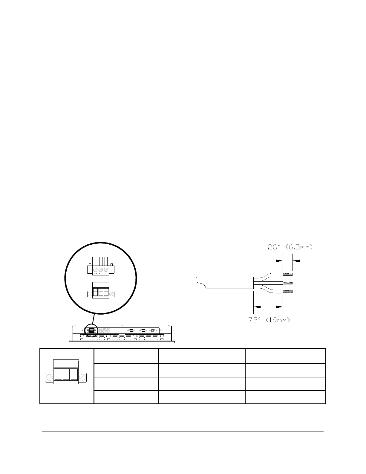
Power is connected to the units through a removable Phoenix Contact plug (Phoenix Contact
P.N. 1777992) that allows f or scr ew term ination of field wir ing. This p lug is includ ed with e ach unit and is
keyed to prevent insta llation in a unit with th e wrong input voltage ratin g. When Field Wiring to these
terminals the use of 18 AWG or greater (12 AWG maximum) copper w ire with 60ºC o r 60/75ºC w ire
insulation and the terminal tightening torque of 7.0 lb/in. (0.79 Nm) is required. The terminal screws
are shown in “T op View” below. Con nect the f ield w iring acc ording to the ap propr iate volt age i n the table
below. Strip the wire insula tion back on each conductor 6.5 mm (0.26 in) and assure that the r emaining
wire is twisted together, no t fra yed, and clea n. If an ou ter jack et over eac h condu ctor is utilized then stri p
the outer jacket back an additional 19.0 mm (0.75 in) as shown in figure below. When installing the
conductors take care t hat there ar e not a ny stray strands of wire that can c on tac t an adj oi ning c onn ec tio n.
Tinning of each lead can be utilized to pre vent frays if desired. Optionally the inc luded protective cover
can be utilized to prevent electr ical shocks when handling the power conn ector and provide strain relief
for each conductor connection (see the following section for installation instructions). After the
connections are made, m ake sure the plug retention screws (the two screws sho wn in the “Front View”
below) are securely tightened. This will prevent the plug from pulling out. The use of these screws is
mandatory when the unit is utilized in applications requiring hazardous locations approvals.
FRONT VIEW
PIN NUMBER 100 VAC – 240 VAC INPUT 18 VDC – 36 VDC INPUT
1 AC Line Input + DC Input
2 AC Neutral Return
- DC Return
3 Protective Earth Ground Protective Earth Ground
Page 14
14
WARNING – EXPLOSION HAZARD – DO NOT DISCONNECT EQUIPMENT
WARNING – EXPLOSION HAZARD – DO NOT DISCONNECT EQUIPMENT
OF IGNITABLE CONCENTRATIONS.
NOTE: TO PREVENT INADVERTENT DISCONNECTION OF VIDEO AND/OR
SUFFICIENTLY TIGHTENED.
NOTE: WHEN USING USB CONNECT ION FO R THE TOUCHSCREEN THE USE
OF THE USB RETENTION BRACKET IS REQUIRED FOR HAZARDOUS
LOCATIONS AND HIGHLY RECOMMENDED FOR NONHARDAOUS
SERIAL TOUCHSCREEN CABLES ASSURE THAT THE THUBSCREWS ARE
WHILE THE CIRCUIT IS LIVE OR UNLESS THE AREA IS KNOW TO BE FREE
UNLESS THE POWER HAS BEEN SWITCHED OFF OR THE AREA IS KNOWN
TO BE NON-HAZARDOUS. USB CONNECTIONS MUST BE SECURED WITH
INCLUDED RETENTION BRACKET – SEE INSTALLATION INSTRUCTIONS
Page 15
15
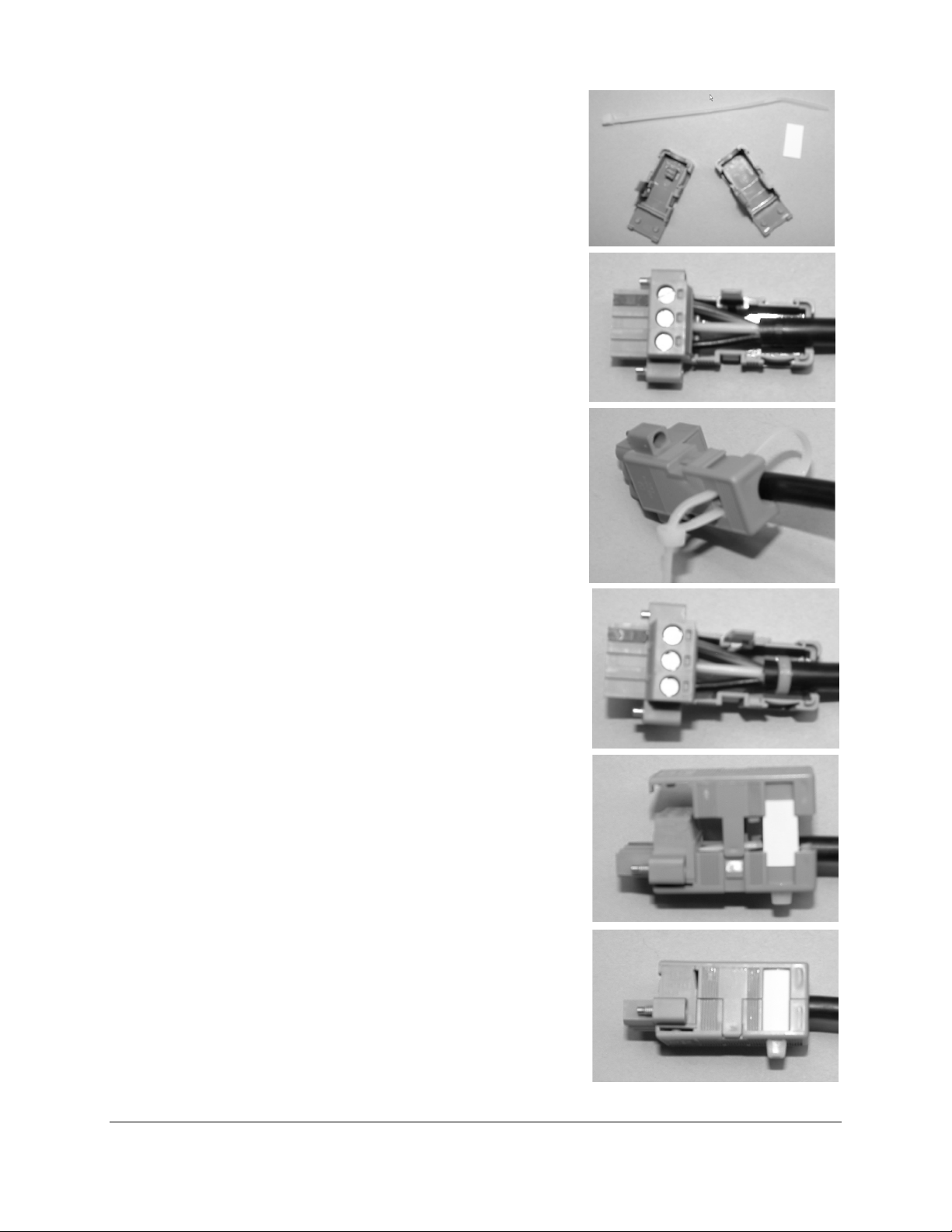
Protective Cover Installation
(Optional if desir e d)
Step 1: Gather the parts of the protective cover; top shell,
bottom shell, label insert, and wire tie. The
picture shows wire tie (top), label insert (right),
bottom shell (left), and top shell (lower right).
Step 2: Insert your pre-wired connector (with the screws
facing up) into the bottom shell. (See manual
for cable wiring instructions).
Step 3: Insert the wire tie from the bottom shell, loop around
the cable and come back out of the opposi te
hole in the bottom shell.
Step 4: Tighten the wire tie around the cable and the
bottom shell.
Step 5: Seat the top shell onto the bottom as shown. Insert
label strip (if desired) in slot on top shell and
bottom shell.
Step 6: Snap the top and bottom shells together.
Page 16
16
SERIAL
RS-232
VGA
USB
"B"
USB
RETENTION
BRACKET
DVI-D
TOUCH SCREEN
CABLES
VIDEO CABLES
(AUTO ADJ)
MENU
DOWN
SELECT UP
(VGA / DVI)
POWER
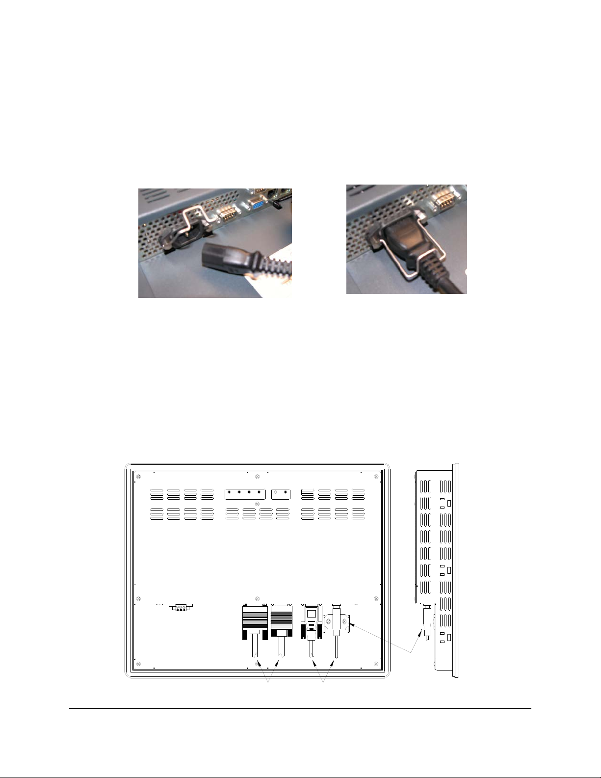
Connecting Power to Enclosed (-EN) units:
The enclosed M-Series units are powered from 100-240 VA C, 50/60 Hz only. Bec ause these are
stand alone Type 1 de vices and do not require an add it ional N EM A type enclosure, a dif f erent t ype pow er
connection is required. These units use a more standard IEC type power cord like found on most
computers. There is a retention clip that can b e utilized to help retain the cord from falling out. A US
three prong cord is suppli ed. If another country connection m ethod is required then an appropriate UL
recognized power cor d can be chosen locall y (not supplied by Nem atron). Optionall y available is an IEC
type connector that can be directly wired to for field wiring. This can be ordered separately from
Nematron and is part number PWR-AC-EN
Enc los ed M-Series IEC Power Cable Power Cable Retention Clip Installed
Connection of VGA and Touch Screen Cables
Connect either a 15-pin VGA or DVI -D cable and either an RS-232 or USB cable if the monitor is
equipped with a touch screen. All communication cables should include a chassis ground shield.
Hazardous location, Division 2, requires that all cables have adequate strain relief. For this reason,
tighten all connector thumb screws securely. If a USB cable is being used, install the provided USB
retention br acket. Insert th e USB c onnector thr ough t he square c utout i n the bas e of the brack et and p ull
the cable and body of the connector back through th e round hole in the bracket f lange. Now insert the
bracket into the two s lots o n t he re ar of the monitor and s ide it f orw ard s o th e c on nec tor is f ully inserted in
the mating bulkhead connector. Install and tighten two 4-40 x .25” Philips screws.
Page 17
17
WARNING – EXPLOSION HAZARD – DO NOT DISCONNECT EQUIPMENT
WARNING – EXPLOSION HAZARD – DO NOT DISCONNECT EQUIPMENT
OF IGNITABLE CONCENTRATIONS.
NOTE: TO PREVENT INADVERTENT DISCONNECTION OF VIDEO AND/OR
SUFFICIENTLY TIGHTENED.
NOTE: WHEN USING USB TOUCHSCREEN CONNECTION THE USE OF THE
AND HIGHLY RECOMMENDED FOR NONHARDAOUS LOCATIONS.
USB RETENTION BRACKET IS REQUIRED FOR HAZARDOUS LOCATIONS
SERIAL TOUCHSCREEN CABLES ASSURE THAT THE THUBSCREWS ARE
WHILE THE CIRCUIT IS LIVE OR UNLESS THE AREA IS KNOW TO BE FREE
UNLESS THE POWER HAS BEEN SWITCHED OFF OR THE AREA IS KNOWN
TO BE NON-HAZARDOUS. USB CONNECTIONS MUST BE SECURED WITH
INCLUDED RETENTION BRACKET – SEE INSTALLATION INSTRUCTIONS
Page 18

18
Turning on the Computer and Monitor
With power applied to the monitor and al l cables c onnected you may power up the com puter and
press the POWER button on the rear of the monitor. T he POWER LED will switch f rom off to green. T he
monitor will perfor m an autom atic self conf iguration and begin displa ying an im age. If no im age appears,
it may be because the monitor has the wrong video i nput s elected. Pr ess the U P butto n on the rear of the
monitor to change between VGA and DVI-D inputs. If the computer is subsequently powered off, the
monitor will rem ain on an d dis pl a y th e NO SIGNAL error message indefinitely. The POWER LED r emains
green. The touch screen r emains active during this ti me. When the computer is powere d on again, the
NO SIGNAL message disappears and normal image display resumes.
Selection of PC Video Settings
Although th e M-Series monitors can dis play several different video m odes, the optimum display
image performance oc curs when the PC’s video settings matc h the native resolution of monitor’s LCD.
For this reason it is rec omm ended that you s et the video m ode op timal f or the s ize M-Series unit that you
have. Refer to the table on Page 5 to determine the optimal resolution for your monitor.
This can be done using W indow’s control panel or by right clicking on t he desktop and choos ing
“Properties”. This will bring up the “Display Properties” menu. From this menu, select the “Setting” tab and
choose the optimal Screen res olution. From the Settin gs menu, c hoose “Advanc ed” and th en clic k on the
“Monitor” tab to set the Screen refresh rate.
Installing the Touch Screen Driver Software
Drivers for the following operating systems are located on the enclosed CD:
Windows 7
Windows Vista*
Windows XP
Windows 2000**
Windows Me
Windows 98
Windows 95
Windows NT 4.0**
DOS and Windows 3.x***
Notes: * The driver for Windows Vista only supports USB touchscreen connections. RS-232 Ser ial
touchscreen and multiple monitor connections are not supported.
** For Windows 2000 and NT 4.0 you must have adminis trator ac ces s rights to install the dr iver .
*** All of the drivers are self extracting and executing except for the DOS and Windows 3.x driver.
This has an install.exe file that will need to be run.
Page 19
19
Chapter 3 - Monitor OSD and Settings
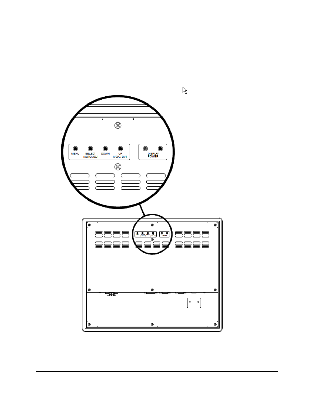
On Screen Display (OSD) Controls
The O SD controls are used for making adjustments to the m onitor’s settings a nd are located on
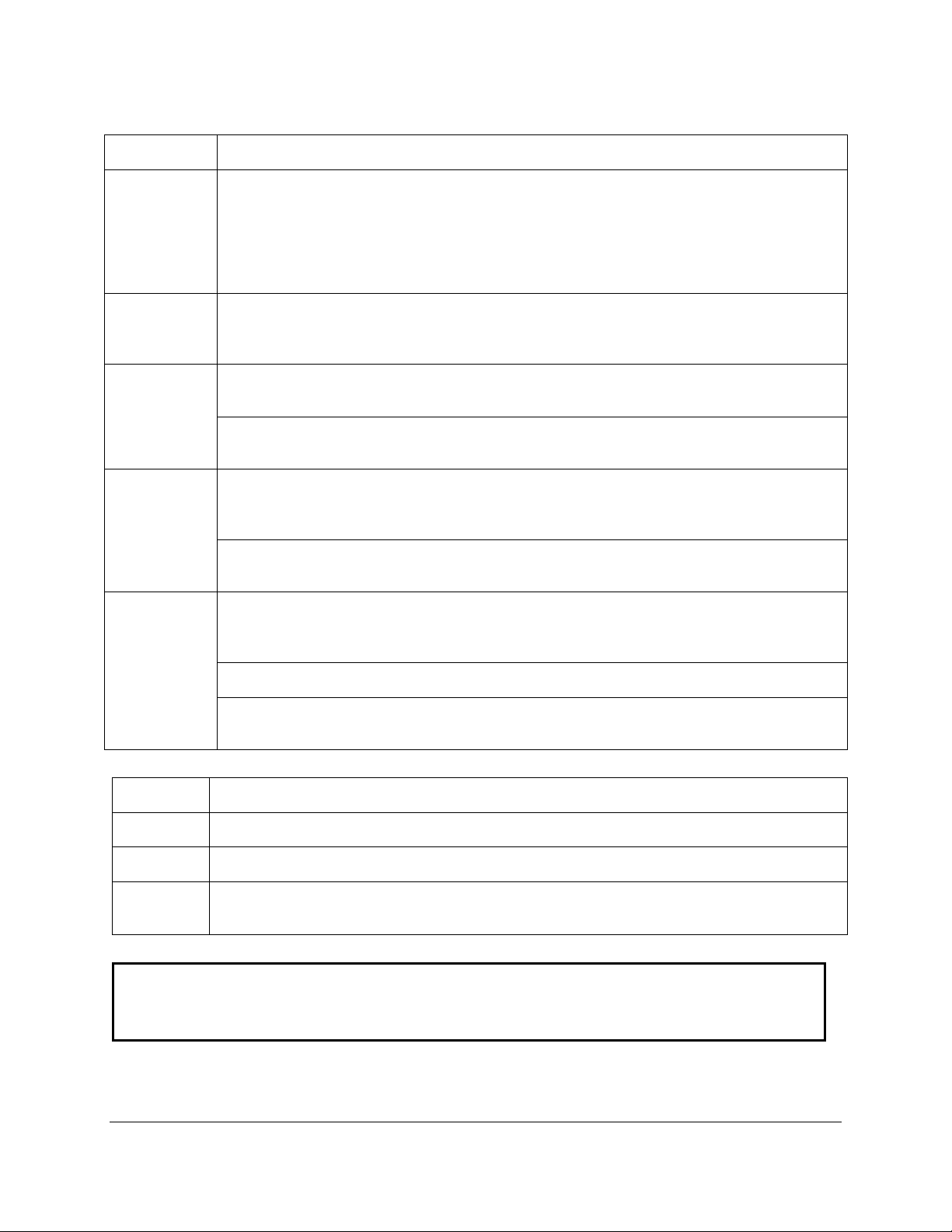
the back of the monitor. They consist of a single LED and five push buttons whose functions are
described in the tables below.
Page 20
20
Button and LED Functions
BUTTON
FUNCTION
monitor electronics and the optional touch screen controller.
main OSD menu will disappear after the set timeout period.
menus. Within a sub-menu, this button selects and deselects menu choices.
configuration and cause the “Processing Auto Configuration” message to be displayed.
for selection.
value.
selection.
When an item has been selected from a sub-menu, pressing this key increases its value.
monitor to switch between VGA (PC) and DVI (Digital) video inputs.
LED
FUNCTION
Not Lit
Power off mode.
Green
Monitor is on and receiving a normal video signal.
receiving a normal incoming video signal.
WARNING - PRESSING THE DISPLAY POWER ONLY REMOVES POW ER TO
DISPLAY POWER IS OFF.
DISPLAY
POWER
MENU Pressing this button causes the m ain OSD menu to be displayed. Pressi ng it again will
SELECT
(AUTO ADJ)
DOWN Within the main OSD menu and sub-menus, this button acts as an down cursor key,
UP
(VGA / DVI)
Pressing this button once wakes the monitor up. Pressing the POWER button again turns
off the back light invert er and puts the monitor in a reduc ed power state but the touch
screen remains activ e. It is impor tant to note that this switch does not d isconnect power
from the monitor. Power is al ways supplied to the internal AC/DC power suppl y (or the
optional 24V DC to DC con verter ) which in tur n, c on tin uall y su pp lies p o wer to t he inter n a l
cause the Main OSD menu to dis appear. If the butto n is not pressed a seco nd time, the
When the OSD main menu is displayed, pressing this button selects one of five sub-
HOT KEY: W hen the OSD is not d isplayed, pr essing t his button will initiat e an autom atic
moving the highlighted item for selection t o move downward to the n ext highlighted item
When an item has been selected from a sub-menu, pressing this key decreases its
Within the main OSD m enu and s ub-menus, this button ac ts as an up c ur sor key, moving
the highlighted item for selection to move upward to the next highlighted item for
HOT KEY: W hen the OSD main m enu is not displayed, press ing this button caus es the
Amber Monitor is on but in DPMS (Displa y Power Man agem ent Signa ling) m ode bec ause it is not
THE BACKLIGHT INVERTER. THE TOUCHSCREEN IS STILL ACTIVE WHEN
Page 21
21
OSD Menus and Settings
MAIN MENU
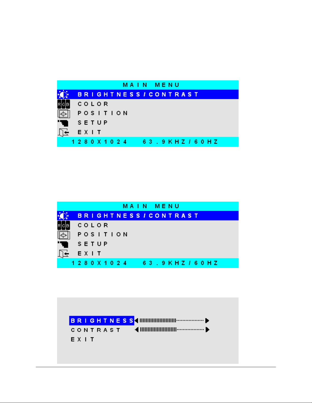
The following section describes the monitor’s OSD menus and settings. With the monitor
powered up and rec eiving a nor m al video signal, press ing the MENU butt on onc e w ill cause the f ollo wing
screen to appear:
Pressing M ENU again will turn this screen of f. Alternatively it will turn off after a time out period
that is set in the SET UP sub-menu. Finally it can be turned of f b y pressing the D OWN button to move the
blue highlighted band down to the EXIT sub-menu and pressing the SELECT button.
The bottom line on this screen displa ys the incoming video hori zontal and vertical resolutio n and
refresh rates.
BRIGHTNESS/CONTRAST
BRIGHTNESS
With BRIGHTNESS/CONTRAST highlighted on the MAIN MENU pressing SELECT will cause
the following screen to be displayed:
Page 22
22
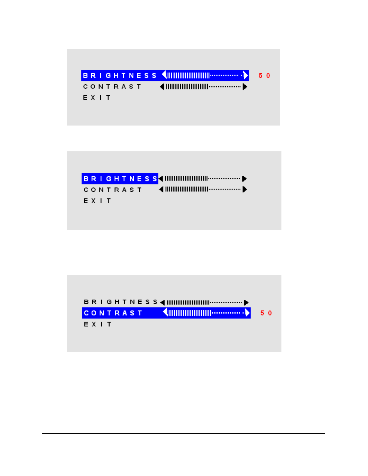
Pressing the SELECT button will cause the following screen to be displayed:
Pressing th e UP and D OWN but tons w ill adjust t he brightn ess ac cordingl y. Pres sing the SEL ECT
button again will deselect this function causing the following screen to appear:
CONTRAST
Pressing the DOW N butt on once and the SEL ECT but ton once will caus e the fol lowing s creen to
appear:
Pressing the UP and DOW N buttons will adjust the contr ast accordingly. Pressing the SELECT
button again will deselect this function. Press the DOWN button to highlight EXIT and then pressing
SELECT will return to the MIN MENU.
Page 23
23
COLOR
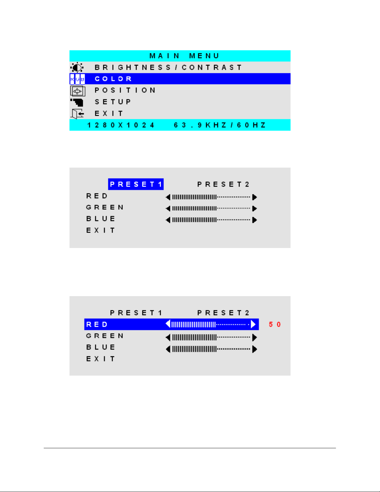
With COLOR highlight ed o n the M AIN MEN U pres s ing SE LE CT will cause the follo win g sc r een to
be displayed:
PRES ET1 and PRESET2 are preset c olor balances. PRES ET1 is produces a bluer scr een while
PRESET2 produces a more aqua screen. Use the UP and Down buttons to highlight PRESET1 or
PRESET2 and press SELE C T to m ak e your selection and return to the MAIN M E NU. I f you highlig ht RED
GREEN or BLU and press select, the following screen appears:
Pressing the UP and DOWN buttons causes the setting to change from the default of 50 to a
value between 0 and 100. Pressing SELECT again saves the setting and deselects the menu item.
Highlighting EXIT and pressing SELECT will return to the MAIN MENU.
Page 24
24
POSITION
A U T O A D J U S T
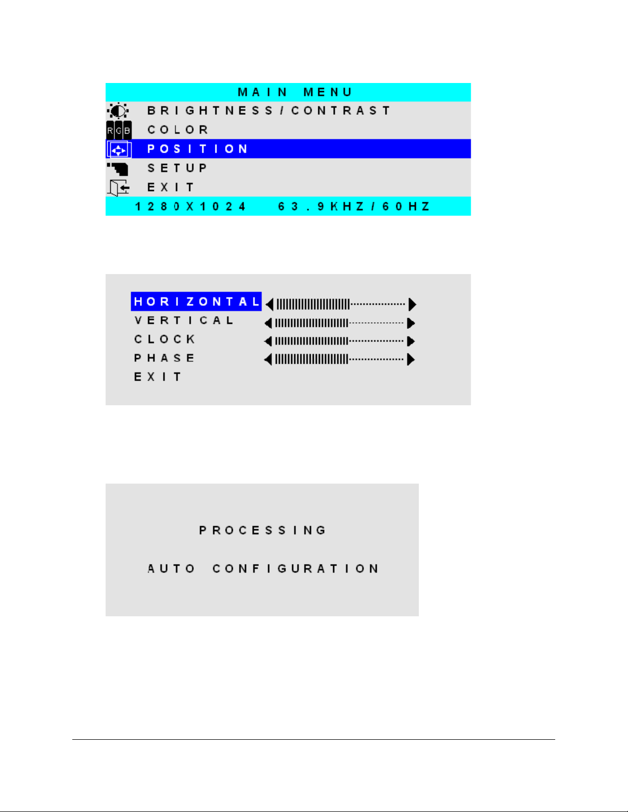
With POSITION highlighted on the MAIN MENU, pressing SELECT will cause the following
screen to be displayed:
AUTO ADJ UST
Highlighting AUTO ADJUST and pressing SELECT will initiate an automatic configuration and
cause the “Processing Auto Configuration” message to be displayed.
During th e auto configuration proces s, the monitor autom atically centers the screen hori zontally
and vertically, sets the clock and optimizes the phase. After the process is complete, the screen is
cleared of the OSD menu.
Page 25
25
HORIZONTAL
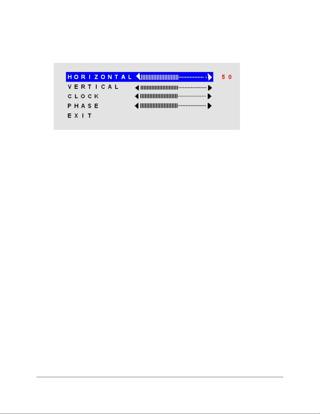
With HORIZONTAL highlighted on the POSITION menu, pressing SELECT will cause the
following screen to be displayed:
Pressing t he UP button caus es the screen to move to the r ight while pressin g the DOWN button
causes the screen t o move to the left. A setting number in th e range of 0 to 1 00 is displayed. Pres sing
SELECT again will deselect the HORIZONTAL menu option and the setting will be saved.
VERTICAL
With VERTICAL highlighted on the POSITION menu, pressing SELECT will display the
VERTICAL adjustm ent menu. Pressing UP will cause the scr een to move upward and pressing DOWN
will cause the screen to move downward. A setting number in the ran ge of 0 to 100 is displayed. Pressing
SELECT again will deselect the VERTICAL adjustment menu and the setting will be saved.
CLOCK
With CLOCK highlighted on the POSITION menu, pressing SELECT will display the CLOCK
adjustment menu. Pressing UP increases the CLOCK and causes the screen to increase in width.
Pressing the DOW N button causes the CLOCK to dec rease and the screen to r educe in width. A sett ing
number in the range of 0 to 100 is displayed. Pressing SELECT again will deselect the CLOCK
adjustment menu and t he setting w ill be saved. Adj ustment of this sett ing is norm ally not needed as it is
automatically set to its o ptim um s etting each tim e the m onitor is turned o n or wh en AUT O ADJ USTMENT
is selected.
PHASE
With PHASE highlighted on the POSITION menu, pressing SELECT will display the PHASE
adjustment menu. Press ing UP increases th e PHASE. Pres sing the DOW N button causes the PH ASE to
decrease. A setting number in the range of 0 to 100 is displa yed. Pressing SELECT again will deselect
the PHASE adjustment menu and the setting will be saved. Adjustment of this setting is normally not
needed as it is autom atically set to its optimum setting each tim e the m onitor is tur ned on or when AUTO
ADJUSTMENT is selected.
Page 26
26
0 1 2 3 4
SETUP
OSD POSITION
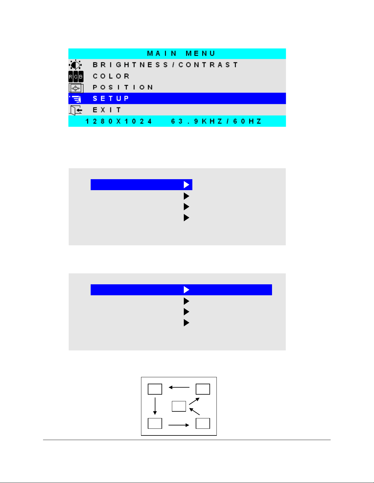
With SETUP highlighted on the MAIN MENU pressing SELECT will cause the following screen to
be displayed:
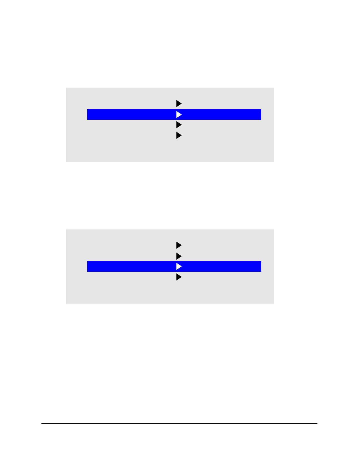
O S D P O S I T I O N
O S D T I M E
L A N G U A G E
3
2 0 S E C
E N G L I S H
I N P U T S O U R C E P C
E X I T
With the OSD POSITION highlighted on the SETUP menu, pressing SELECT will cause the
following screen to be displayed:
O S D P O S I T I O N
O S D T I M E
L A N G U A G E
3
2 0 S E C
E N G L I S H
I N P U T S O U R C E P C
E X I T
The default position of the OSD menu is 3 which is in the center of the screen. Pressing the UP or
DOWN buttons will cause the OSD to move in the pattern below:
Page 27
27
Pressing SELECT aga in will deselect the O SD POSITION adjustm ent menu and the setting will
be saved.
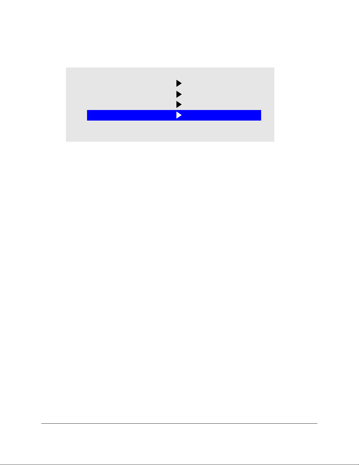
OSD TIME
With OSD TIME highlighted on the SETUP menu, pressing SELECT will cause the following
screen to be displayed:
O S D P O S I T I O N
O S D T I M E
L A N G U A G E
3
2 0 S E C
E N G L I S H
I N P U T S O U R C E P C
E X I T
Pressing t he UP and DOWN butto ns will the allow adj ustment of the O SD time out setting in the
range from 5 to 60 s econds. Pressing SELECT again will deselect the OSD TIME menu a nd save the
current setting.
LANGUAGE
With LANGUAGE highlighted on the SETUP menu, pressing SELECT will cause the following
screen to be displayed:
O S D P O S I T I O N
O S D T I M E
L A N G U A G E
3
2 0 S E C
E N G L I S H
I N P U T S O U R C E P C
E X I T
Pressing the UP and DOWN buttons allows the following LANGUAGE choices:
ENGLISH
FRANCAIS
DEUTSCHE
ITALIANO
ESPANOL
Pressing SELECT will deselect the LANGUAGE option menu and save the current selection.
Page 28
28
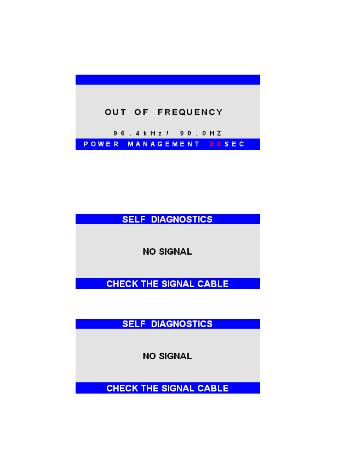
INPUT SOURCE
With INPUT POSITION highlighted on the SETUP menu, pressing SELECT will cause the
following screen to be displayed:
O S D P O S I T I O N
O S D T I M E
L A N G U A G E
3
2 0 S E C
E N G L I S H
I N P U T S O U R C E P C
E X I T
Pressing the UP and DOWN buttons switches between PC (the 15-pin analog VGA input
connector) and DIGITAL (the DVI-D input connector) Pressing SELECT will deselect the INPUT SOURCE
option menu and save the current selection.
Page 29
29
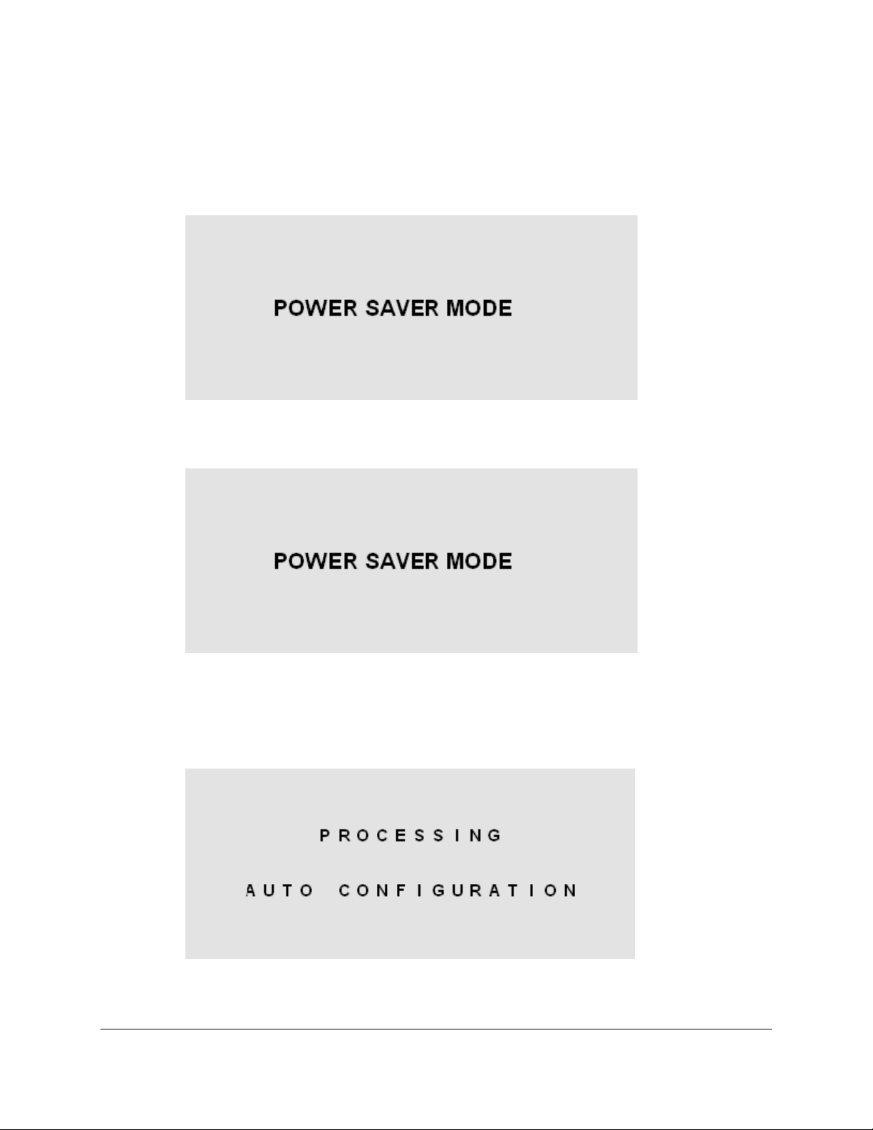
OSD Message Displays
PC
DIGITAL
OUT OF FREQUENCY The follo wing OSD message will appear if the hor izontal or vertical refresh rate of the incoming
video signal is outside the range of the monitor.
NO SIGNAL
When the monitor is first turned on it performs a set of self diagnostics. If no incoming video
signal is detected immediately following self diagnostics, the following message will appear. This
message will rem ain displayed indefinitel y until a valid signal is de tected. The LED rem ains green. The
“PC” NO SIGNAL mess age indicates the monitor is setup to receive incom ing video through the 15-pin
analog VGA input connector.
The “DIGITAL” NO SIGNAL message indicates the monitor is setup to receive incom ing video
through the DVI-D input connector.
Page 30
30
POWER SAVER MODE
PC
DIGITAL
The following message appears when the monitor is on but in DPMS (Display Power
Management Signaling) mode. This occurs after a valid incoming vide o s ig na l is no lon ger pr es et or whe n
the PC has signaled t he monitor to enter the POWER SAVER MOD E. The message is displayed f or 5
seconds and then removed. The LED remains amber. The “PC” POWER SAVER MODE message
indicates the monitor is setup to receive incoming video through the 15-pin analog VGA input connector.
The “DIGITAL” POWER SAVER MODE message indicates the monitor is setup to receive
incoming video through the DVI-D input connector.
PROCESSING AUTO CONFIGURATION
The f ollowing message appears when the m onitor is performing an autom atic self configuration.
An auto configuration can be initiated by pressing the SELECT button with no OSD screen being
displayed or by selecting the AUTO ADJUST option from the POSITION OSD menu.
Page 31
31
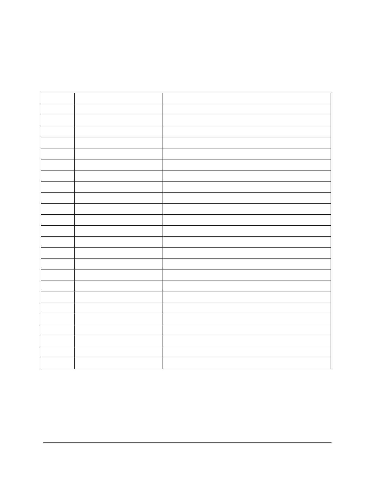
Appendix
Video Input Pin Assignment
DVI-D
Pin No. Name Description
1 TMDS DATA2- TMDS DATA2 Differential Negative Signal
2 TMDS DATA2+ TMDS DATA2 Differential Positive Signal
3 TMDS DATA2 Shield Shield for TMDS Channel #2
4 N.C. No Connection
5 N.C. No Connection
6 DDC Clock The Data Line for the DDC Interface
7 DDC Data The Clock Line for the DDC Interface
8 N.C. No Connection
9 TMDS DATA1- TMDS DATA1 Differential Negative Signal
10 TMDS DATA1+ TMDS DATA1 Differential Positive Signal
11 TMDS DATA1 Shield Shield for TMDS Channel #1
12 N.C. No Connection
13 N.C. No Connection
14 +5V Power +5 Volt signal for EDID
15 GND (+5V Return) Ground for +5 Volt Power
16 HPD Hot Plug Detect
17 TMDS DATA0- TMDS DATA0 Differential Negative Signal
18 TMDS DATA0+ TMDS DATA0 Differential Positive Signal
19 TMDS DATA0 Shield Shield for TMDS Channel #0
20 N.C. No Connection
21 N.C. No Connection
22 TMDS CLOCK Shield Shield for TMDS Clock Differential Pair
23 TMDS CLOCK+ TMDS CLOCK Differential Positive Signal
24 TMDS CLOCK- TMDS CLOCK Differential Negative Signal
Page 32
32
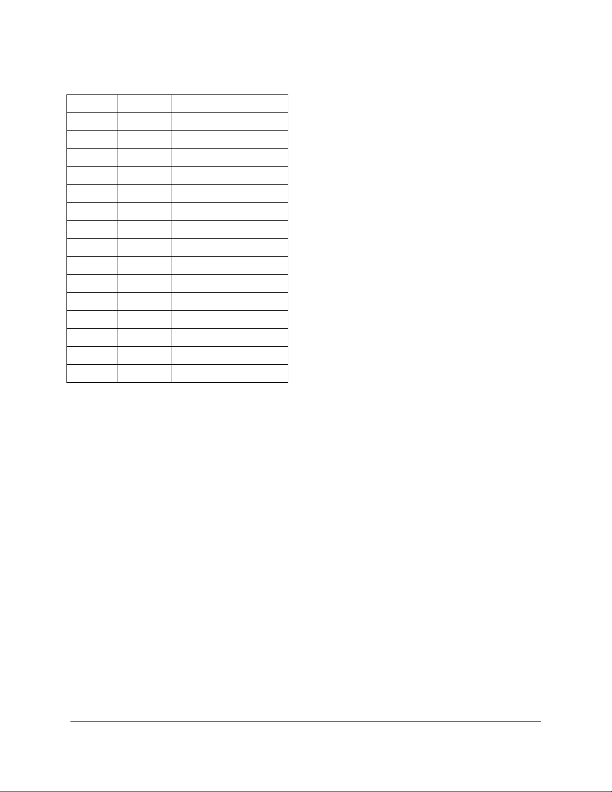
Analog 15- Pin D-Sub
Pin No. Name Description
1 Red Red Analog Data
2 Green Green Analog Data
3 Blue Blue Analog Data
4 GND Ground
5 GND Ground
6 GND Ground
7 GND Ground
8 GND Ground
9 N.C. No Connection
10 GND Ground
11 GND Ground
12 DSDA DDC Serial Data
13 HSYNC Horizontal Sync
14 VSYNC Vertical Sync
15 DSCL DDC Serial Clock
Page 33
33
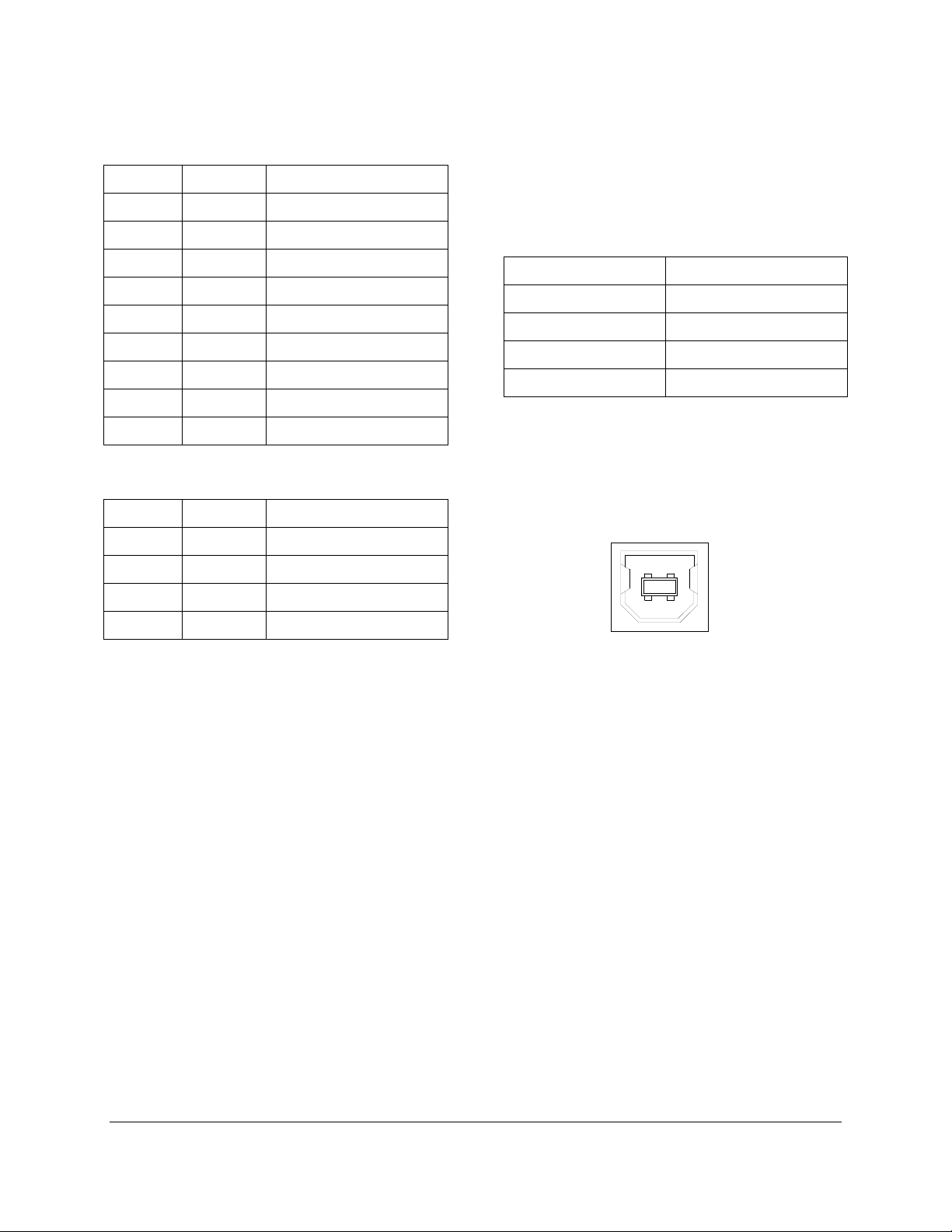
1 2
4
3
USB-B CONNECTOR ON
REAR OF MONITOR
Touch Screen Pin Assignment
Serial RS-232
Pin No. Name Description
1 DCD Data Carrier Detect
2 RX Receive Data
3 TX Transmit Data
4 DTR Data Terminal Ready
5 GND Ground
6 DSR Data Set R ea d y
7 RTS Request To Send
8 CTS Clear To Send
9 RI Ring Indicator
USB
Pin No. Name Description
1 VBUS +5V Power
2 USB_D− USB Data −
3 USB_D+ USB Data +
4 GND Ground
Baud Rate 9600
Data Size 8 Bits
Stop Bits 1 Bit
Parity No Parity (Only)
Handshaking Hardware CTS/RTS
Note: The touch controller receives it power from the monitor’s internal power supply – not through the USB conn
 Loading...