

Page 1
e
User’s Guide
Document No. DOC-IPC-002,
User Manual ePC-Plus & nPC200, Rev D Rel. 9-2012
High Performance Ultra-Thin
PC-Plus & nPC200
Industrial Computers
Page 2

2
Revision Number
Description of Change
Release Date
B
Revision for Field Wiring Requirements
5-2010
C
Added nPC200, -EN, and –RM options
12-2011
Nematron reserves the right to make changes in specifications described herein at any time without
responsibility for damage caused by misuse or improper use of its products.
Revision List
A Initial Release 7-2009
D UL Required changes for UL 1604 to ANSI/ISA 12.12.01-2012
Conversion
notice in order to improve design and r eliability. Nematron do es not assume any respons ibility for
the use of any circuitry de scribed; no circuit patent licenses are im plied. Nematron assumes no
9-2012
WARRANTY
Nematron warrants to Customer that the Products will be free from defects in material and
workmanship under norm al use and service for a period of two years f rom date of invoice. Customer’s
exclusive remed y for breac h of this war rant y is th at Nematron will either ( i) rep air or re place, a t its opti on,
any Product which fails dur ing the warranty period because of suc h defec t (if Custom er prompt ly reported
the f ailure to Nematron in wri ting) or, ( ii) if Nematron is unable to rep air or replac e, Nematron will ref und
the purchase price of the Product upon its return to Nematron. This warranty does not apply to any
Product which has b een s ubj ected t o m isuse, ab norm al servic e or handling , or which has bee n altered or
modified in design or construction, or which has been serviced by anyone other than Nematron. The
warranty set forth herein is in lieu of, and exclusive of, all other warranties, express or implied.
Document No. DOC-IPC-002, User Manual ePC-Plus & nPC200, Rev D Rel. 9-2012
Page 3

3
Chapter 1 - Introduction
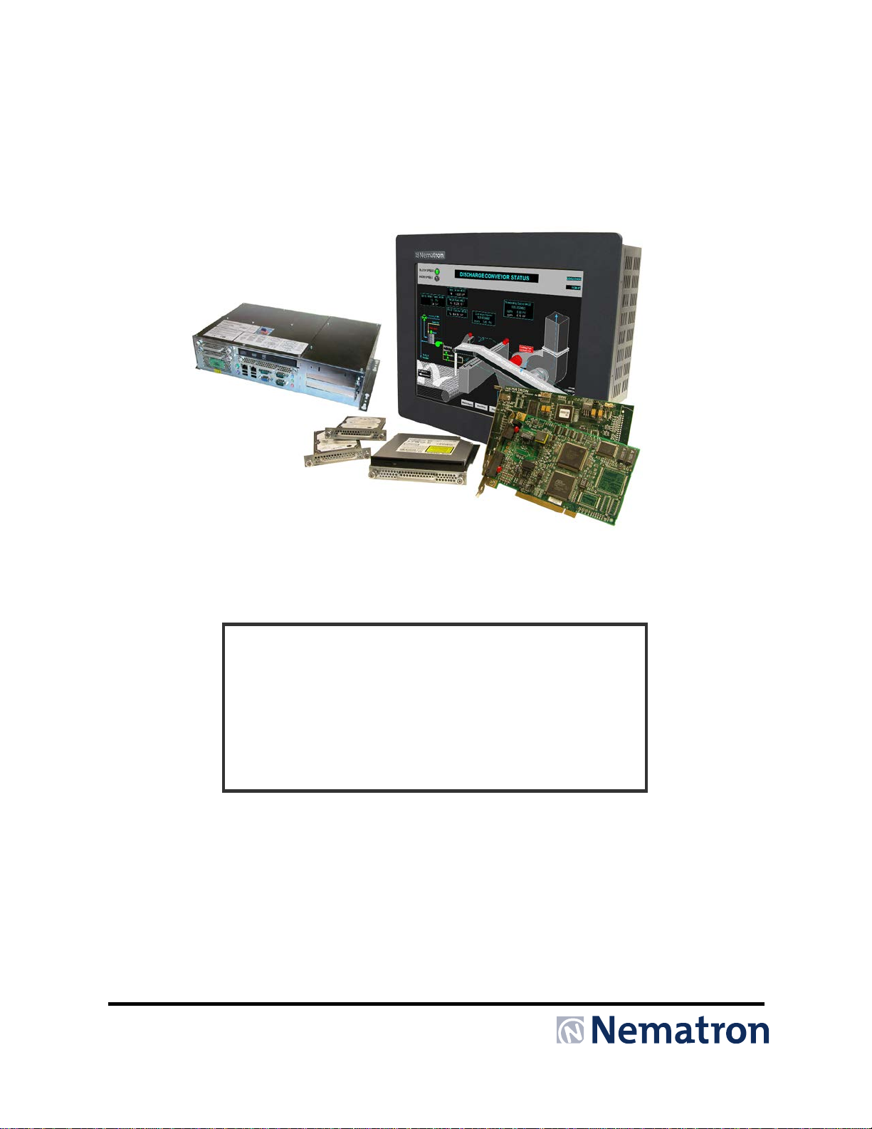
The ePC-Plus Series products are high performance color TFT embedded ultra-thin industrial
computers specif ical l y d es igned for harsh industri al en viro nments. This ser ies is an extension t o t he ePCSeries with added features including DVD-R/W, Dual hard drives, and PCI expansion.
The ePC-Plus Series off ers four versions with 15” XG A (1024 x 768), 17” SXGA (1280 x 1024),
19” SXGA (1280 x 1024) TFT Color LCD panels, or no attached LCD (nPC200). These high-performance
embedded industria l PCs offer processor options up t o a state of the art Int el Core 2 Duo Processor and
DRAM options up to 4 GB. W ith a multitude of I/O and 2 ¾-length PCI expansi on slots included on the
standard unit many automation applications are ideally suited for use with this series. The Ultra-Thin
panel depth (4.45”) also mak es this series ideal for space constrained ap plications. With Class I and II
Division 2 approvals this industrial PC makes installation in Hazardous Locations applications simple.
Features
• Processor Options up to Intel Core 2 Duo 2.2 GHz opt i ons
• DRAM Options up to 4 GB
• Up to two 250 GB (minimum) easily removable SATA hard drives
o Solid State SATA hard drive upgrade option
o High Reliability SATA options
• Numerous I/O Ports
o Two Gigabit Ethernet ports
o 4 USB 2.0 ports
o 2 RS-232 serial port
o 1 RS-422/485 Serial port
o PS/2 mouse and ke yboard por ts
o Audio (In/Out/Mic)
o Analog VGA port for dual screen applications (with attached LCD installed)
• UL 508 and ANSI/ISA 12.12.01-2012 listed for Hazardous Locations: Class I, Division 2, Groups
A, B, C, D and Class II, Division 2, Groups F and G, Class III when installed in a NEMA Type
1/4/4x/12 enclosure (does not include the optional enclosed (-EN) units)
• NEMA 4/4X/12 front bezel (panel mount versions only)
• Optional Vented back enclosure (-EN option)
o ePC1500 only.
• 2-Year warranty
• RoHS compliant
• European CE mark compliant
• Integral 100 -240 VAC power supply
• Simplified installation with no studs
• Ultra-Thin design – less than 4.45” behind front panel
• VESA compliant – all modes up to SXGA, 75Hz (XGA on 15” unit)
• Optional 5-wire resistive touch screen
• Optional 304 stainless steel front bezel
• Optional ePC1950 Rack Mount front bezel (not NEMA sealed)
• Optional 24 VDC input power
• Windows XP Professional (Windows Vista and Windows 7 are optional)
Page 4
4
Specifications
Front Panels
The ePC-Plus ser ies has NEMA 4/4X/12 sealed front panels when mounted in an appropriate
NEMA rated enclosure. See Chapter 2 for more details on installation and selection of an appropriate
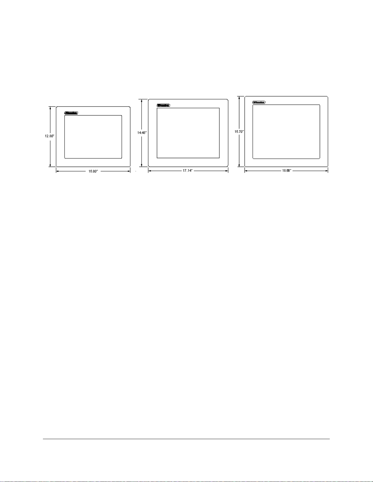
enclosure. All three sizes have very similar front panels with different dimensions.
ePC1550 ePC1750 ePC1950
Figure 1.0: ePC-Plus Series Front Panel Comparison
The standard front p anels are p owder coat ed aluminum . The optiona l Stainless Steel front panel is type
304 and will not contain a logo pock et or logo on the f ront. T he window area is c lear pol ycarbo nate when
ordered without a to uchscreen. The touchsc reen option is chemicall y strengthened glass covered by a
polyester overlay. The polyester overlay has better resistance to chemicals than the polycarbonate
window. Depending on the chemicals involved in your application consideration should be given to
choosing the proper window material.
In addition to the pane l m ounted versio ns ther e is a di spla y-less “node” vers ion, the nPC200. T his uni t is
essentially the sam e as the other ePC-Plus units wit hout a NEMA sealed front panel, touc hscreen, and
display. It is intended to be mounted inside a NEMA enclosure.
Page 5
5
I/O Panel
Feature
Description
Video Port
A standard 15-pin analog VGA is provided. This connection allows a second screen
for more details on this feature.
Com 1
Com 1 is a standard 9-pin RS-232 serial port.
Com 2
Com 2 utilizes a standard 9-pin serial port. The ePC default configuration for this
information on the configuration of this port.
Com 3
Com 3 is a standard 9-pin RS-232 serial port.
Gigabit Ethernet
Two Ethernet ports are provided that are both capable of 10/100/1000 Base-T
communications.
USB 2.0
Four ports capable of USB 1.1 and USB 2.0 are provided.
PS/2 Port
One PS/2 port is provided. This port is capable of being used singularly as a mouse
to the appropriately marked cable end.
Input Power
Input power, whether AC or DC, is supplied via a Phoenix connector. See Chapter 2
on Installation for more details on how to wire this connection.
SATA Hard Drive
An easily removable high speed Serial ATA hard drive is provided. The captive
drives an easy task.
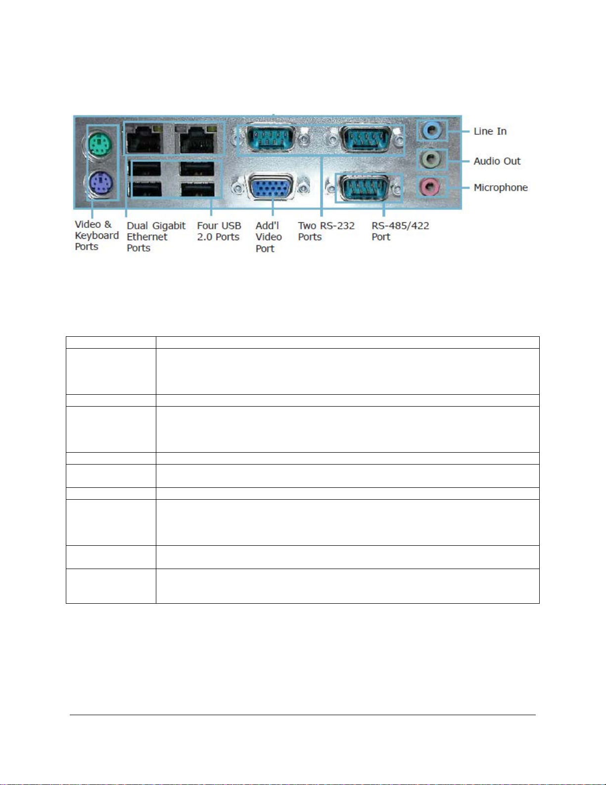
All three versions of the ePC-Plus ser ies have a common Input/ Output configuration. Figure 2.0 shows
the base configuration of the three units.
Figure 2.0: ePC-Plus Series I/O configuration
to be easily added to the ePC. In addition the ePC allows this second screen to be
utilized in an extended desktop configuration. See section on configuring the video
port is RS-485. Via a jumper this port can alternately be configured as RS-422. See
section on connector pin-outs and jumpers for more detailed instructions and
or keyboard port. If both devices are desired to be utilized simultaneously the
supplied Y-cable cable must be utilized. The keyboard or mouse must be connected
retention hardware, lack of cumbersome cables, and handle make changing hard
Page 6
6
ePC1550
ePC1750
ePC1950
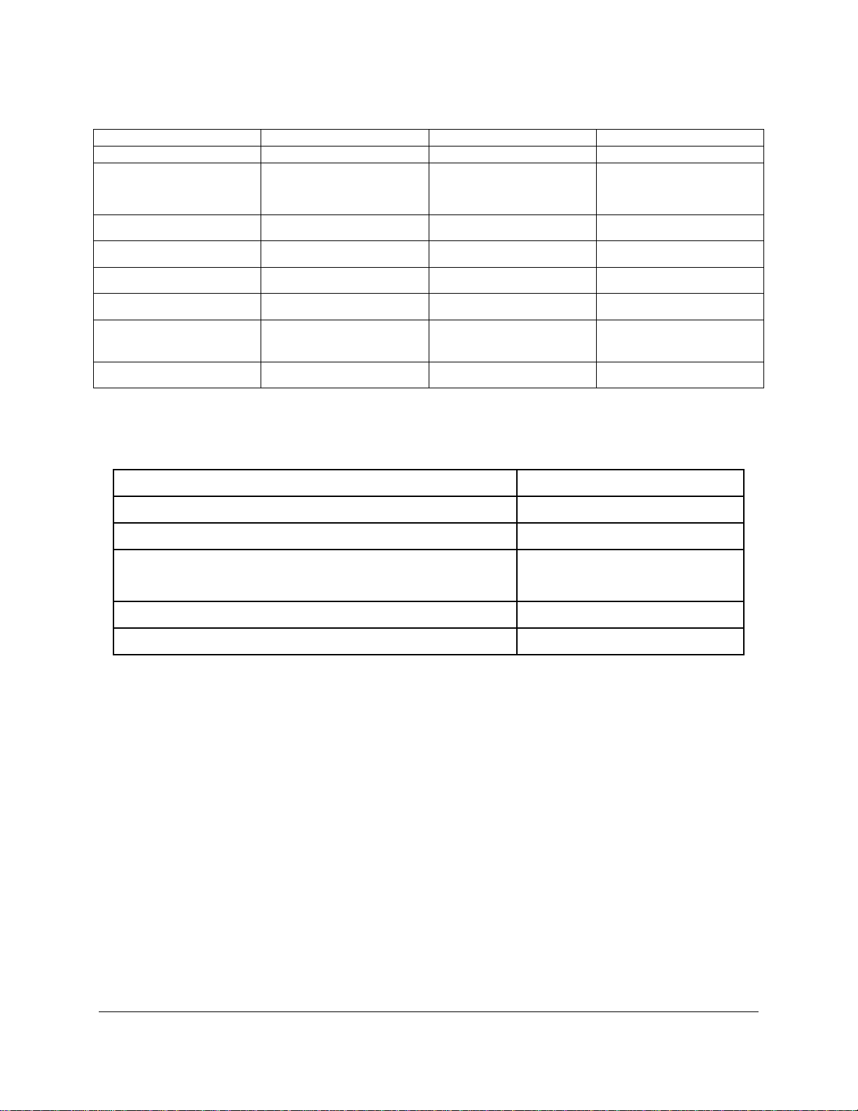
Display Diagonal
15.0” (381.0mm)
17.0” (431.8mm)
19.0” (482.6mm)
Display Size (Active
DISPLAY
11.97” x 8.98”
Area H x V)
Native Resolution XGA, 1024 x 768 SXGA, 1280 x 1024 SXGA, 1280 x 1024
Displayable Colors 16M 16M 16M
Brightness, Typical 300 Nit 380 Nit 300 Nit
Contrast Ratio, Typical 800:1 1000:1 2000:1
Horizon/Vertical View
Angle, CR>5, Typical
Backlight Life, Typical 50,000 hrs 50,000 hrs 50,000 hrs
TOUCH SCREEN (Optional)
Touch Screen Technology 5- Wire Analog Resistive
Interface Internally via USB
Resolution 4096 x 4096
Positional Accuracy (Maximum Error) 0.18” (0.19” ePC1900)
(304.0mm x 228.1mm)
150°/145° 176°/170° 178°/178°
13.30” x 10.64”
(337.8mm x 270.3mm)
14.82” x 11.85”
(376.4mm x 301.0mm)
4.57mm (4.83mm ePC1900)
Positional Accuracy (Standard Deviation of Error) < 0.08” (< 2.0 mm)
Expected Life >35,000,000 Activations
Page 7
7
PHYSICAL
ePC1550
ePC1750
ePC1950
Over All Dimensions
(H x W x D)
Panel Mounting Depth 4.3” (109.2mm) 4.3” (109.2mm) 4.45” (113.0mm)
Cutout Dimensions
(H x W)
Weight 20.0 lbs (9.07kg) 24.0 lbs (10.88kg) 28.0 lbs (12.7kg)
Shipping Weight 25.0 lbs (11.33kg) 29.0 lbs (13.25kg) 33.0 lbs (14.96kg)
Option Weight (SS)*
* Additioanl weight for Stainless Steel Front Panel option.
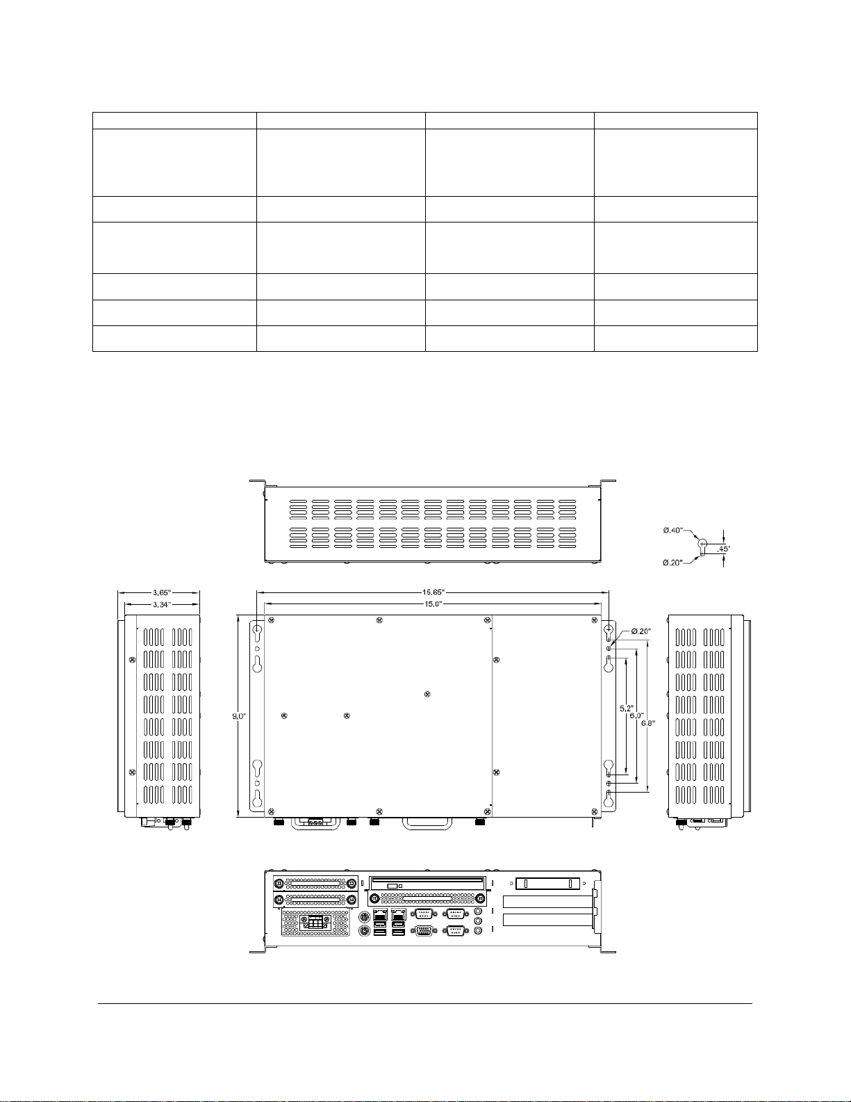
The nPC200 is essential ly the re ar of th e panel mount versions. It is s upplied with m ounting br ackets so
that it can be easily attached to wall or shelf in a NEMA 1 or better enclosure. The nPC200 is not a
standalone device as the –EN units and must be installed in an enclosure to protect operators.
The dimensions of the nPC200 unit are as follows:
12.80” x 15.80” x 4.55”
(325.1mm x 401.3mm x
115.6mm)
12.00” x 15.00”
(305mm x 381mm)
+3.5 lbs (1.58kg) +3.75 lbs (1.7kg) +4.0 lbs (1.81kg)
14.48” x 17.14” x 4.55”
(367.8mm x 435.4mm x
115.6mm)
13.70” x 16.35”
(348mm x 415.3mm)
15.70” x 18.66” x 4.70”
(398.8mm x 474.0mm x
119.4mm)
14.90” x 17.75”
(378.5mm x 450.9mm)
Page 8
8
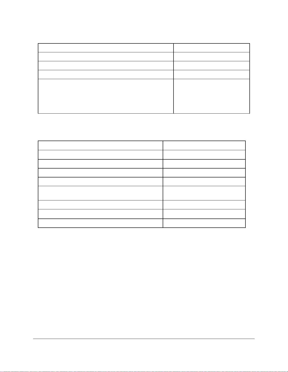
ELECTRICAL
AC Input Voltage 100 – 240 VAC, 47-63 Hz
AC Input Current 2.0 A Maximum
DC Input Voltage (Optional) 18 – 36 VDC
DC Input Current (Optional) 7.5 A Max
Input Power nPC200 – 60 W Typical*
ePC1550 - 70 W Typical*
ePC1750 – 80 W Typical*
ePC1950 – 90 W Typical*
* Typical Power is m easured witho ut an y add itional I/O or exp ansi on opt ions. An y addit ional I/ O ins talled
during application can increase this value.
ENVIROMENTAL
Operating Temperature
0°C to 50°C
Non-Operating Temeperature
Operating & Non-Operating Humidity 20% to 80% RH, noncondensing
Operating Shock* 15g peak acceleration, 11msec
Non-Operating Shock 30g peak acceleration 11msec
Operating Vibration (5-2000 Hz) 1 0.006” peak to peak displacement,
Non-Operating Vibration (5-2000 Hz) 1
Operating Altitude 2 Sea level – 10,000 feet
Non-Operating Altitude 2 Sea level – 40,000 feet
1 Shock and Vibration specifications are established using Solid State drives and non-rotating media.
2 Altitude Specification is established by using all internal component specifications.
-20°C to 60°C
1g maximum acceleration
Page 9

9
AGENCY
CE, EN 55022: Class A,
s A,
2,
NOTE (NPC200 UNITS): SUITABLE FOR USE IN CLASS I, DIVISION 2,
FOR USE ON A FLAT SURFACE OF A TYPE 1 ENCLOSURE WITH
NOTE (PANEL MOUNT VERSIONS):
Front Panel NEMA Rating NEMA 4/4X/12, IP65
FCC 47 CFR, Part 15, Class A
EU CE Marking Compliance
EN 61000-3-2: Clas
EN 61000-3-3, EN 61000-6-
Safety Agency Approvals UL 508 Listed, ANSI/ISA 12.12.01-
2012 Listed*, cUL Listed CSA C22.2,
#142, CSA C22.2, #143*
* See appropriate note below for the applicable unit or option being utilized.
SUITABLE FOR USE IN CLASS I, DIVISION 2, GROUPS A, B, C AND D, CLASS
II DIVISION 2, GROUPS F AND G, CLASS III HAZARDOUS LOCATIONS, OR
NONHAZARDOUS LOCATIONS ONLY
FOR USE ON A FLAT SURFACE OF A TYPE 1, 4, 4X, OR 12 ENCLOSURE
WITH PROVISIONS FOR CLASS I DIVISION 2 WIRING METHODS
TEMPERATURE CODE: T5
GROUPS A, B, C AND D HAZARDOUS LOCATIONS, OR NONHAZARDOUS
LOCATIONS ONLY
PROVISIONS FOR CLASS I DIVISION 2 WIRING METHODS
TEMPERATURE CODE: T5
Page 10

10
WARNING – EXPLOSION HAZARD – DO NOT DISCONNECT EQUIPMENT
WARNING – EXPLOSION HAZARD – DO NOT DISCONNECT EQUIPMENT
OF IGNITABLE CONCENTRATIONS.
NOTE: (ENCLOSED EPC VERSIONS):
NOTE (RACK MOUNT VERSIONS):
TALLATION ON A TYPE 1 ENCLOSURE WITH
WARNING – EXPLOSION HAZARD – SUBSTITUTION OF ANY COMPONENTS
MAY IMPAIR SUITABILITY FOR CLASS I, DIVISION 2
SUITABLE FOR USE IN CLASS I, DIVISION 2, GROUPS A, B, C AND D, CLASS
II DIVISION 2, GROUPS F AND G, CLASS III HAZARDOUS LOCATIONS, OR
NONHAZARDOUS LOCATIONS ONLY
FOR RACK MOUNT INS
PROVISIONS FOR CLASS I DIVISION 2 WIRING METHODS
TEMPERATURE CODE: T5
A LISTED VESA STYLE MOUNT SUITABLE WITH A MINIMUM LOAD RATING
OF 40 POUNDS SHALL BE USED IN THE END INS TALLATION
FOR USE IN NONHAZARDOUS LOCATIO NS ONLY
TYPE 1 ENCLOSURE
WHILE THE CIRCUIT IS LIVE OR UNLESS THE AREA IS KNOW TO BE FREE
UNLESS THE POWER HAS BEEN SWITCHED OFF OR THE AREA IS KNOWN
TO BE NON-HAZA RDOUS. PS/2 AND AUDIO CONNECTORS A RE FOR SETUP
AND MAINTENANCE ONLY, USB CONNECTIONS MUST BE SECURED WITH
INCLUDED RETENTION BRACKET – SEE INSTALLATION INSTRUCTIONS
Page 11

11
15.0"
±.02"
12.0"
±.02"
Chapter 2 - Installation of Computer
The panel mount versions of the ePC-Plus units are inten ded to be mounted in and used wher e
NEMA 1, NEMA 4/4x and NEMA 12 type enc losures are employed. Enclosures made of heavier gauge
metal work better because they won’t deform or bend as easily when the monitor’s sealing gasket is
compressed. The monitor meets NEMA 4/12 sealing specifications when properly installed in an
approved NEMA enc losure constructed from 14-gaug e or hea vier ste el. T he com puter uses “U”-shaped
clips and a special gasket to achieve the proper seal.
When selecting an enclos u re r em em ber to allo w ad eq uate s pace ar oun d th e r ear of the computer
for good air flow. Do not bl oc k air flow from below or a bov e th e monitor. If possible mount the computer in
a vertical orientation. T he unit is designed t o work in e nvironments up to 50 degrees Cent igrade ambient
temperature inside the enc losure. Remember to account for heat diss ipated from other equipment that
may be installed inside the same enclosure.
To install the computer , make a cutout accordin g to the diagrams below in one of the walls of
your NEMA enclosure. N ex t hold the u nit in plac e whi le you ins tall t he m ounting clips. T ighten the c lips
to the point were the b ack of the unit’s f ront bezel j ust begins to co ntact the f ront of the N EMA encl osure.
The use of an adjustable torque driver is recommended. The screws should be tightened to 8 inchpounds. Tighten the clips i n a cross pattern. This will help to develop an even pr essure on the sealing
gasket. DO NOT OVER T IGHTEN AS DAMAGE CAN RESULT IN THE COMPUTER C AUSING LOSS
OF SEALING INTEGRITY.
Cutout Pattern for ePC1550 / ePC1550T Industrial Computer
Page 12

12
16.35"
±.02"
13.70"
±.02"
14.90"
±.02"
17.75"
±.02"
Cutout Pattern for ePC1750 / ePC175 0T Industrial Computer
Cutout Pattern for ePC1950 / ePC1950T industrial Computer
Page 13

13
UPMENU DOWNSELECT POWER
FRONT PANEL
OF NEMA
ENCLOSURE
TIGHTEN TO 8
INCH-POUNDS
COMPRESSABLE NEMA
SEALING GASKET
.25" THICK MONITOR
FRONT BEZEL
MAXIMUN ALLOWABLE
PANEL THICKNESS
CUT AWAY
.325"
FRONT PANEL OF
NEMA ENCLOSURE
MOUNTING CLIP
WITH 10x32 SCREW
Mounting Clip Installation
NOTE: WHEN INSTALLING THE MOUNTING CLIPS TIGHTEN THE SCREWS
BREAKAGE..
REAR VIEW OF PANEL
MOUNTED ePC-Plus
TO 8-10 INCH-POUNDS MAXIMUM. OVERTIGHTENING THE SCREWS WILL
RESULT IN A COMPRIMISED NEMA SEAL A ND MAY CAUSE TOUCH SCREEN
Page 14

14
nPC200 Unit Installation
The nPC200 is inte nded to be mounte d on the f lat sur face on th e insi de of a NEMA T ype 1, 4/ 4x
or NEMA 12 enclosure. See the specifications section for the dimensions and mounting dimensions
required for mounting this unit.
When selecting an enclosu re remember to allow adequate space aro und the computer for good
air flow. Do not block air flo w around the unit except for the m ounting surface. The computer can be
mounted on a horizontally or vertically to a wall or shelf within th e enc l osur e. The unit is designed to work
in environments up to 50 degr ees Centigrade ambient temperatur e inside the enclosure. Remember to
account for heat dissipated from other equipment that may be installed inside the same enclosure.
Rack Mount Unit Installation
The ePC1950 with a rack m ount front panel is intended to be mounted to a 19. 0” wide rack in a
NEMA Type 1 or better enclos ure. The unit can be mounted using standard r ack mount hardware (not
supplied) via the eight (4 each side) counter-bored holes in the front of the panel. The front panel is
intended to be mounted in a vertical height of 9 U (16. 0”) on the r ack. This unit is not NEM A s eal ed when
mounted like the panel mount versions.
When selecting an enclosure remember to allow adequate space around the rear side of the
computer for good air flo w. The unit is designed to work in environm ents up to 50 degrees Centigrad e
ambient temperature inside the enclosure. Remember to account for heat dissipated from other
equipment that may be installed inside the same enclosure.
Enclosed Unit Installation
The enclosed ePC-Pl us products ar e intende d to be s tand-alone N EMA T ype 1 units. T hese are
required to be mounted to a VESA style mount with a m inimum load rating of 40 pou nds. A desktop
stand, wall mount, or articulat ing arms are examples of VESA style mounts that can be utilized. These
units are vented for air flow and ar e not dust or water proof. Care should be tak en to not utilize these
units in areas where h igh concentrat ion of part iculate m atter or moisture are pr esent. If these conditions
do exist then the us e of the pane l mount versions in an appropr iate NEMA 4, 4x, or 12 enc losure shou ld
be considered. The warranty may be voided if high levels of moisture or particulate matter are
determined to be the c a us e of a f ail ur e. T he eP C -Plus –EN units h ave filters on the rear to f i lter incoming
air. These filters should be c arefully removed and cl eaned periodicall y depending on service c onditions.
In some applications this may need to be checked and cleaned often.
These units are designed to work in environments up to 50 degrees Centigrade ambient
temperature around th e enclosure. Impeding the airflow arou nd this unit or clogged filters will sever ely
affect the reliability of the unit by raising the internal tem perature. Assure that there is adequate airf low
around the unit.
NEMA Type 1 is not sealed against water and/or dust; it is simply provides protection from
operators shocking themselves. It also offers a certain amount of fire containment it the event of a
catastrophic failure ins ide the unit. As stated previous ly NEMA 1 is not waterproof or dust proof and is
not intended to be utilized in environments exhibiting high levels of these conditions.
Example of an Enclosed Unit Mounted
To a Stand
Page 15
15
321
31 2
TOP VIEW
FRONT VIEW
PHOENIX CONTACT P.N. 1777992
Connecting Power to the ePC-Plus
31 2
Connecting power to the Panel Mount, Rack Mount, and nPC120 units:
The ePC-Plus and nPC200 un its are po wered f rom 100-240 VAC, 50/60 H z or op tionally fr om 24
VDC. Damage will occu r if 100-240 VAC power is connected to an
24 VDC input power option. ePC-Plus e quipped units with t he 24 VDC opt ion wil l have a “-D C” suf fix in
their model number such as ePC1550-MC5500-1GB-HD-DVD-XP-DC or ePC1550T-T7500-2GB-HD-
DVD-XP-DC.
Because the ePC-Plus (not –EN option) is UL 1604 listed for Hazardous Locat ion use, (Class I
Division2, Groups A, B, C, D; Class II D ivision 2 Grou ps F and G: Tem perature Code T4A), the u nits do
not have a power s witch fo r switchin g off s upplied po wer. Cons ideration s hould be give to t he insta llation
of an appropriatel y rated external power switch if the application r equires powering off the ePC-Series
unit.
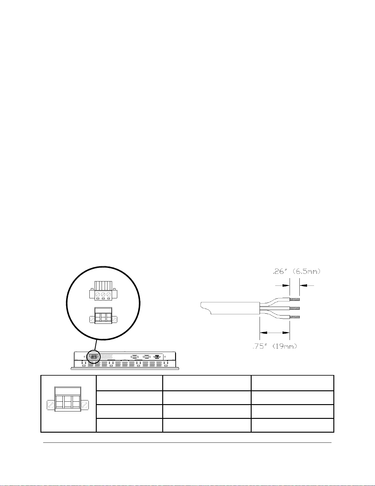
Power is connected to the units through a removable Phoenix Contact plug (Phoenix Contact
P.N. 1777992) that allows f or scr ew term ination of field wir ing. This p lug is includ ed with e ach unit and is
keyed to pr event installation in a u nit with the wrong input vo ltage rating. When Field Wiring to these
terminals the use of 18 AWG or greater (12 AWG maximum) copper w ire with 60ºC o r 60/75ºC w ire
insulation and the terminal tightening torque of 7.0 lb/in. (0.79 Nm) is required. The terminal screws
are shown in “T op View” below. Con nect the f ield wir ing acc ording to the ap propr iate volt age i n the table
below. Strip the wire insula tion back on each conductor 6.5 mm (0.26 in) and assure that the rem aining
wire is twisted toget her, not f rayed, and c lean. If an outer j acket over each co nduc tor is util ized then s trip
the outer jacket back an additional 19.0 mm (0.75 in) as shown in figure below. When installing the
conductors take care t hat there ar e not a ny stray strands of wire that can c on tac t an adj oi ni ng conn ec tio n.
Tinning of each lead can be utilized to pre vent frays if desired. Optionally the inc luded protective cover
can be utilized to prevent electr ical shocks when handling the power conn ector and provide strain relief
for each conductor connection (see the following section for installation instructions). After the
connections are made, m ake sure the plug retention screws (the two screws sho wn in the “Front View”
below) are securely tightened. This will prevent the plug from pulling out. The use of these screws is
mandatory when the unit is utilized in applications requiring hazardous locations approvals.
ePC-Plus unit equipped with the
FRONT VIEW
PIN NUMBER 100 VAC – 240 VAC INPUT 18 VDC – 36 VDC INPUT
1 AC Line Input + DC Input
2 AC Neutral Return
- DC Return
3 Protective Earth Ground Protective Earth Ground
Page 16

16
WARNING – EXPLOSION HAZARD – DO NOT DISCONNECT EQUIPMENT
WARNING – EXPLOSION HAZARD – DO NOT DISCONNECT EQUIPMENT
OF IGNITABLE CONCENTRATIONS.
NOTE: TO PREVENT INADVERTENT DISCONNECTION OF VIDEO AND/OR
SERIAL TOUCHSCREEN CABLES ASSURE THAT THE THUBSCREWS ARE
SUFFICIENTLY TIGHTENED.
NOTE: WHEN USING USB CONNECTIONS THE USE OF THE USB RETENTION
BRACKET IS REQUIRED FOR HAZARDOUS LOCATIONS AND HIGHLY
RECOMMENDED FOR NONHARDAOUS LOCATIONS.
WHILE THE CIRCUIT IS LIVE OR UNLESS THE AREA IS KNOW TO BE FREE
UNLESS THE POWER HAS BEEN SWITCHED OFF OR THE AREA IS KNOWN
TO BE NON-HAZARDOUS. THE PS/2, LINE IN, LINE OUT, AND MIC PORTS
ARE FOR SETUP AND MAINTE NANCE ONLY, USB CONNECTIONS MUST BE
SECURED WITH INCLUDED RETENTION BRACKET – SEE INSTALLATION
INSTRUCTIONS
Page 17
17
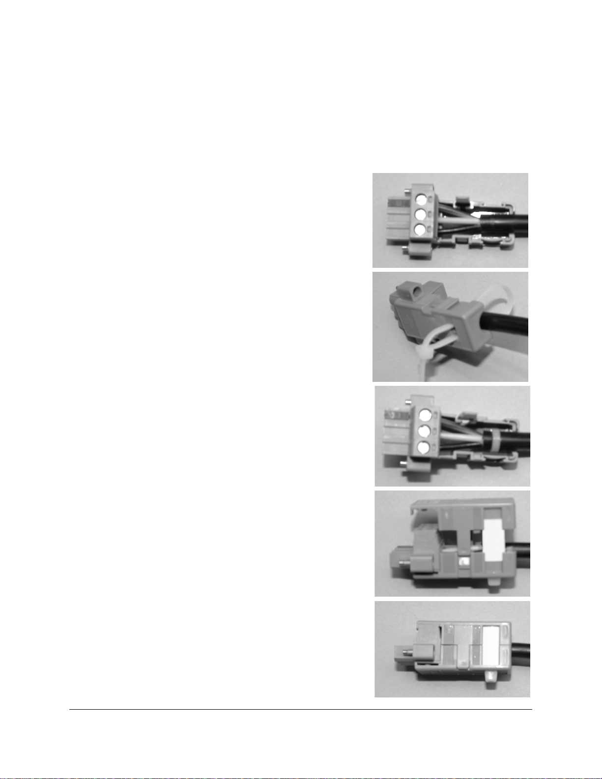
Protective Cover Installation
(Optional if desir e d)
Step 1: Gather the parts of the protective cover; top shell,
bottom shell, label insert, and wire tie. The
picture shows wire tie (top), label insert (right),
bottom shell (left), and top shell (lower right).
Step 2: Insert your pre-wired connector (with the screws
facing up) into the bottom shell. (See manual
for cable wiring instructions).
Step 3: Insert the wire tie from the bottom shell, loop around
the cable and come back out of the opposi te
hole in the bottom shell.
Step 4: Tighten the wire tie around the cable and the
bottom shell.
Step 5: Seat the top shell onto the bottom as shown. Insert
label strip (if desired) in slot on top shell and
bottom shell.
Step 6: Snap the top and bottom shells together.
Connecting Power to Enclosed (-EN) units:
Page 18
18
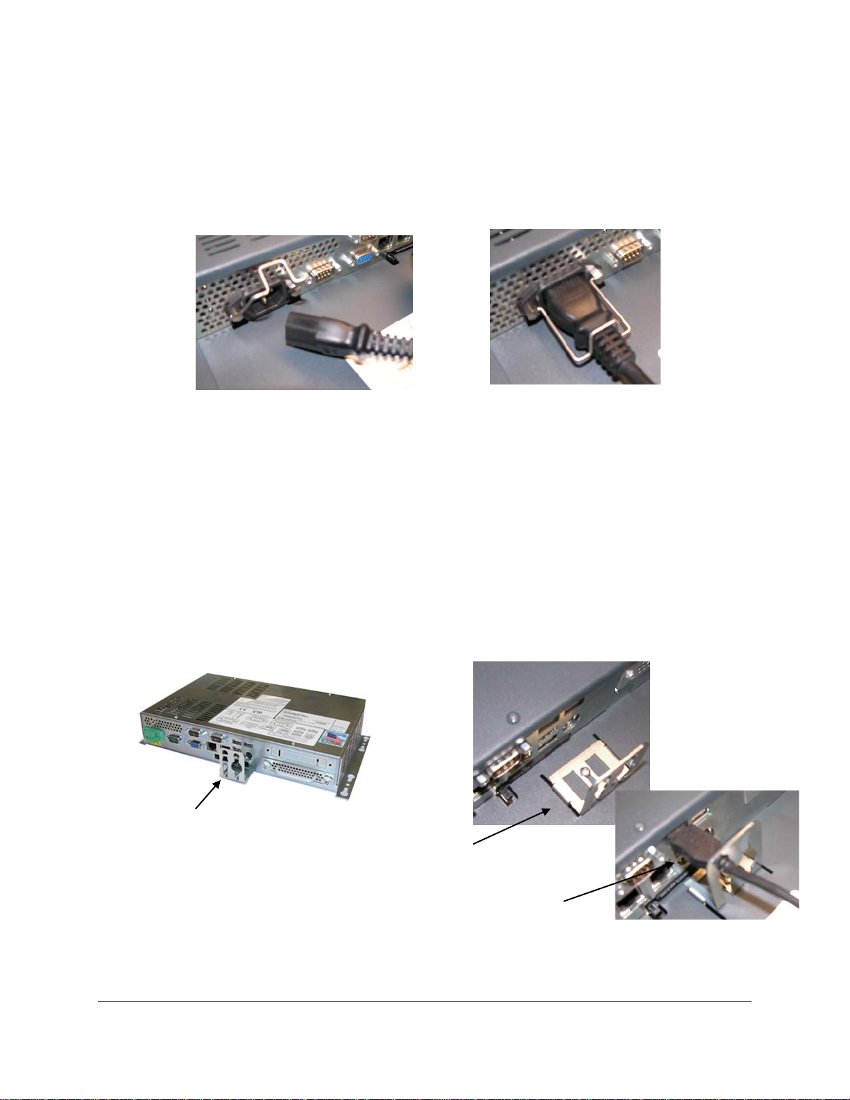
The enclosed ePC-Pl us units are powered f rom 100-240 VAC, 5 0/60 Hz on ly. Becaus e these are
stand alone Type 1 de vices and do not require an add i tion al N EM A type enclosure, a diff er ent t ype po wer
connection is required. These units use a more standard IEC type power cord like found on most
computers. There is a retention clip that can b e utilized to help retain the cord from falling out. A US
three prong cord is suppli ed. If another country connection m ethod is required then an appropriate UL
recognized power cord c an be chosen locall y (not supplied by Nem atron). Optionall y available is an IEC
type connector that can be directly wired to for field wiring. This can be ordered separately from
Nematron and is part number PWR-AC-EN
Enclosed ePC-Series IEC Power Cable Power Cable Retention Clip Installed
I/O Cable Management
The ePC-Plus units include a retention mechanism for securing USB connections. USB
connections are not secure and can easily fall out. The use of this mechanism is suggested for all
applications and is required for any ha zardous locations installat ions. Simply rem ove the bracket insert
your USB cables through the bracket. Connect your USB cables to the unit and m ove the bracket into
position. Snugly push the bracket toward the USB connector and secure with the screw provided.
On the ePC panel mount , Rack Mount, and Enclos ed units th e USB br ack et is a sim ple L s haped
bracket with cutouts to retain up to four USB cables and a mounting screw. On the nPC200 the bracket is
two pieces; one (flat piece) is s ec ured to t h e bott om of the unit using two #4-4 0 s cr e ws and th en th e oth er
functions the same as the ePC-Series USB retention bracket.
nPC200 USB Retention Bracket
ePC-Series USB Retention Bracket
With USB Cable Installed
Page 19
19
Video and the Serial connections have jack screws in the connectors that can be utilized to
WARNING – EXPLOSION HAZARD – DO NOT DISCONNECT EQUIPMENT
WARNING – EXPLOSION HAZARD – DO NOT DISCONNECT EQUIPMENT
OF IGNITABLE CONCENTRATIONS.
NOTE: TO PREVENT INADVERTENT DISCONNECTION OF VIDEO AND/OR
SERIAL TOUCHSCREEN CABLES ASSURE THAT THE THUBSCREWS ARE
SUFFICIENTLY TIGHTENED.
NOTE: WHEN USING USB CONNECTIONS THE USE OF THE USB RETENTION
REQUIRED FOR HAZARDOUS LOCATIONS AND HIGHLY
RECOMMENDED FOR NONHARDAOUS LOCATIONS.
secure your cable end to the un it. Ethernet connections have a plastic tab that pr events the connection
from falling out. The k eyboard/m ouse por t (splitter pr ovided) is not s ecured an d is intende d for s etup and
maintenance only when in an area that is known to be nonhazardous.
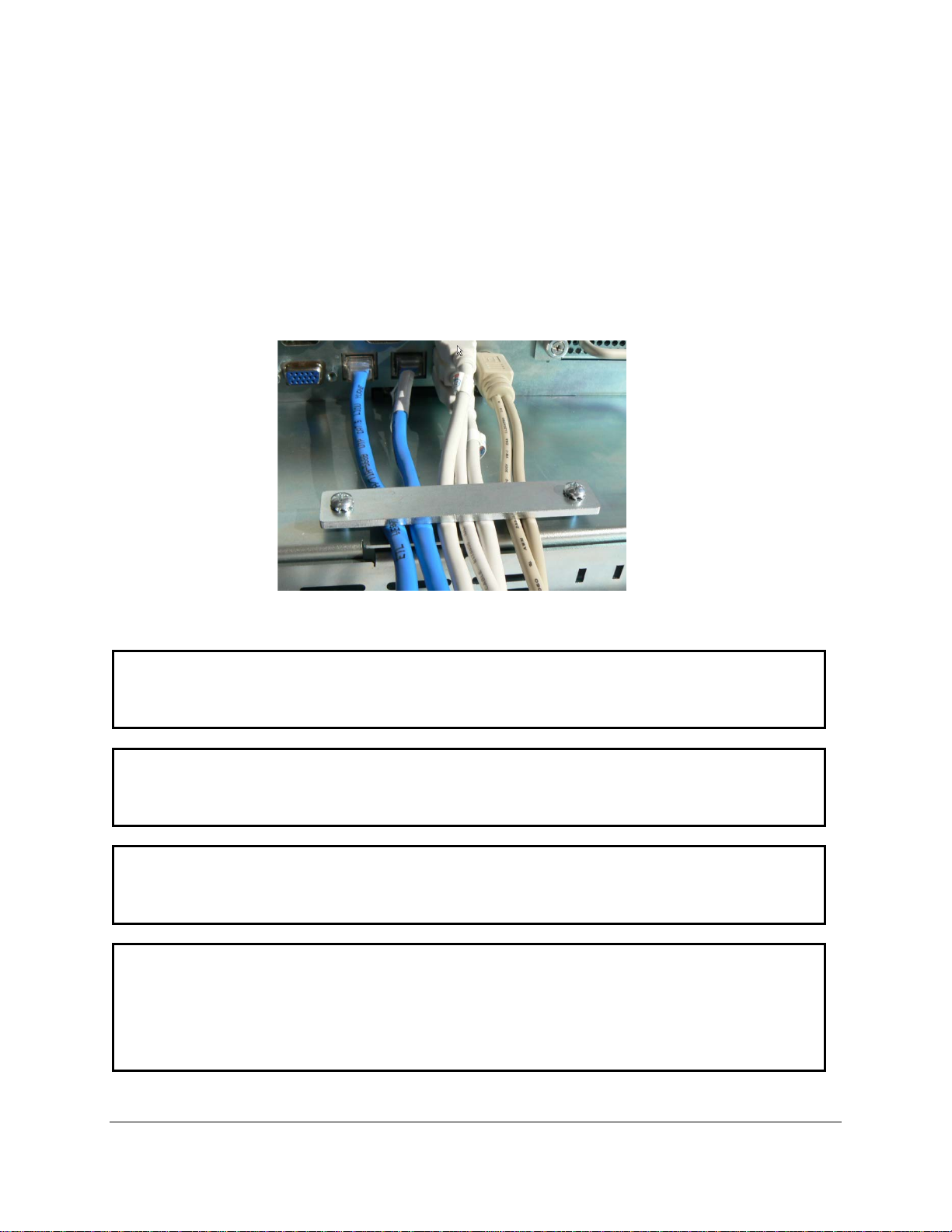
See the connecting p ower section for details o n securing the power c onnections. In addit ion to
the USB Bracket there is a n additional cable m anagem ent bracket at the bottom of the units that can b e
utilized to strain relief c ables. This is a flat bracket attached by 2 sc rews which can be utilized to hold
down cables or provides a n attachment poi nt for a cable tie to be us ed for securing cabl es. Care should
be taken to provide an ade quate radius for an y cable being utilized. Too t ight a radius can dam age the
conductors. When tighten ing this securing bar care should be t aken not to over crush cables; this can
damage conductors.
Cable Securing Bar Installed
BRACKET IS
WHILE THE CIRCUIT IS LIVE OR UNLESS THE AREA IS KNOW TO BE FREE
UNLESS THE POWER HAS BEEN SWITCHED OFF OR THE AREA IS KNOWN
TO BE NON-HAZA RDOUS . PS /2 A ND AUDI O CONNE CTORS ARE FOR SETUP
AND MAINTENANCE ONLY, USB CONNECTIONS MUST BE SECURED WITH
INCLUDED RETENTION BRACKET – SEE INSTALLATION INSTRUCTIONS
Page 20

20
Hard Drive Removal and Replacement
These products are equipped with an easily removable SATA hard drive. They are designed so
that there is no need to remove the cover on these units to change a hard drive. The only reason to
remove the cover will be to switch the configurable serial port from RS-485 to RS-422. See the
appropriate board manual included on the “Documentation and Driver” disk for procedure on changing
this port. The hard drive is simply removed by loosening the two thumbscrews and pulling the drive out.
Remove all power to the unit before removing the drive.
There are no cables to remove when pulling the drive from the chassis. Once the drive is
removed there are four screws on the back of the bracket that hold the drive. If the drive is being
replaced these screws secure the drive to the plate. To reinstall the drive simply insert the bracket with
hard drive attached into the chassis and slide forward. Completely push the drive in and secure the
thumbscrews before reapplying power to the unit.
Various hard drive options with a mounting bracket pre-installed are available for purchase from
Nematron. If a spare hard drive is required these are recommended. These spare hard drives can be
used with third party software to create complete system backups for your installation.
Hard Drive Removal
Page 21

21
Installing the Touch Screen Driver Software
If your ePC is ordered with a touchscreen and an operating system the drivers will be preinstalled. The ePC-Series utilizes a USB connection for the touchscreen, therefore the touchscreen will
only function with operating systems that can recognize and utilize USB connections. The driver
included with these units functions with Windows 2000, XP, VISTA, and Windows 7. If using the nPC200
with a touchscreen monitor the appro priat e driver w i ll be inc luded w ith the monitor.
Operating System Recovery
If for some reason your operating system needs to be reinstalled Nematron provides an
Operating System or Recovery disk. The procedure for this is dependent on the operating system.
Because this series does not have an integrated DVD you will need a US B DVD-ROM drive. In some
cases you will also need the “Documentation and Driver” disk that is included with each unit.
The ePC-Series products are only shipped with Windows XP Professional SP3, Windows Vista
Business Edition, and Windows 7 Professional. Use of other operating systems is not recommended and
not supported.
Windows XP Professional SP3 for Embedded Systems
Standard Windows XP operating system disks are no longer available from Microsoft. In order to
continue shipping Windows XP for Automation applications, Nematron had to switch to a different license
scheme, Windows XP Professional SP3 for Embedded Systems. This is not Embedded XP it is simply a
different license procedure. By switching to this license Nematron had to create a system recovery disk.
This disk is very specific to the platform and options that are included on your unit. Do not attempt to use
a recovery from one type of unit on another, it may not work. This recovery disk installs the factory image
with all drivers installed. On these units you will need an USB DVD-ROM. Follow the instructions on the
recovery DVD for installation. When installing the image from this DVD it will not be “Activated”, unlike
when you received the unit. You may need to set the video resolution after loading the image depending
on the unit you are loading.
Windows Vista and Windows 7
Windows Vista and Windows 7 are supplied with an OEM operating system license and disk. .In
order to reinstall these operating systems the operating system is installed first via the included disk and
then the “Documentation and Driver” disk must be utilized to install the approved drivers for chipset,
video, Ethernet, and touchscreen if not functional during operating system installation. Use of different
drivers than included on the disk are not recommended and not supported.
Page 22
22
Chapter 3. – ePC-Plus CPU and BIOS
Consult the ePC-Plus Series CPU Board User manual for more detailed specifications of the CPU board
and BIOS details. This section will concentrate on the features of the ePC-Plus Series units that are
externally accessible. In addition any internal details that may need adjusting will be discussed.
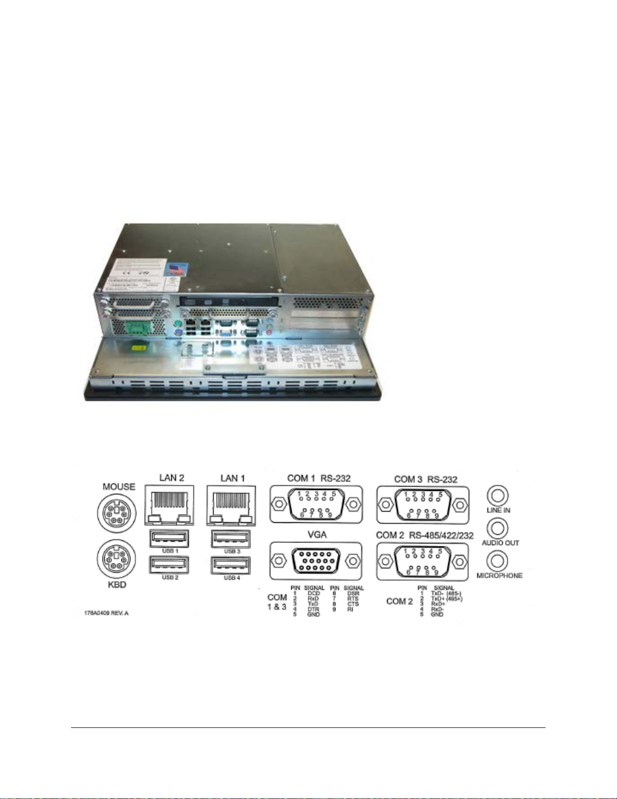
External I/O Connections
The following figure shows the externally accessible connections.
Pinouts
 Loading...