

MAKERS WARRANTY
Part No: W1980
Version B - 2006
COOKTOP MODEL
T2596NOAU
Installation instructions
User instructions
This cooktop is approved for use with Natural and Propane gases
Leave these instructions with the owner
Contents 3
Introducing your cooktop 4-6
❍ Dear customer
❍ Accessories
❍ Notes on disposal
❍ Gas supply
❍ Electrical supply
❍ What to do if you smell gas
❍ Safety considerations
Installation instructions 7-11
❍ Installer instructions
❍ Statutory requirements
❍ Overall dimensions
❍ Preparing to install
❍ Overhead clearances
❍ Side clearances
❍ Bottom clearance and heat barrier
❍ Bench top specifications
❍ Special considerations for installation over
under bench oven
❍ Installation procedure
❍ Electrical connection
❍ Gas connection
❍ Energy consumption
Gas conversion instructions 12-13
❍ Boiling burners main injector conversion
❍ Boiling burners turn down injector
conversion
❍ Outer wok burner main injector
conversion
❍ Inner wok burner main injector
conversion
Data plate
This appliance is imported and distributed by:
For service to this appliance
Please contact:
Sampford & Staff P/L
52-70 Sparks Avenue
Fairfield, Vic, 3078
Phone: 1300 727 421
Email service@sampford.com.au
User instructions 14-17
❍ Important information
❍ Burner location and control panel
❍ Boiling burners operation and ignition
❍ Wok burner assembly
❍ Wok burner operation
❍ Ventilation requirements
2 23
Contents
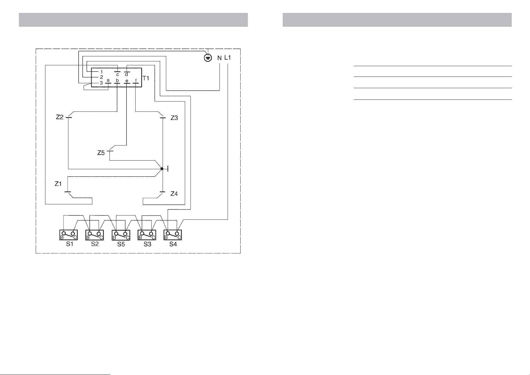
Wiring diagram
❍ Additional pan supports
❍ Recommended pan diameters
❍ Cooking recommendations
Do not & Do 18
Cleaning 19
Maintenance trouble shooting 20
Service 21-23
❍ To remove the hob
❍ To service gas control valves
❍ To replace the thermocouple
❍ To replace the electronic ignition module
❍ To replace internal wiring and the gas
control ignition micro switch
❍ Wiring diagram
❍ Data plate
❍ For service to this appliance
22
3
Introducing your cooktop Service
Dear customer
We thank you and congratulate you on your choice.
This carefully designed product, manufactured with the highest
quality materials, has been carefully tested to satisfy all your cooking
demands.
We therefore request that you read and follow these easy
instructions which will allow you to obtain excellent results right
from the start.
The cooktop is fitted with four boiling burners (one large, two medium and one simmer burner) and a wok burner. All burners are
fitted with electronic spark ignition and flame failure device. The
wok burner is supplied with a supplementary wire pan support for
smaller pans. An additional wire pan support is supplied to fit
over the boiling burner pan supports to support small vessels such
as a coffee pot.
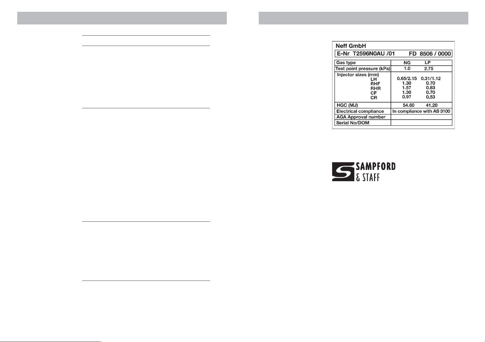
The cooktop’s data plate is accessible even with the cooktop fully
installed. It is positioned on the bottom of the unit. A duplicate
copy is supplied at the back of the instruction booklet. Always
quote the details from it to identify the appliance when ordering
spare parts or requesting a service.
In case of a malfunction, turn off the cooktop’s gas supply
before contacting the service centre for assistance.
Only an authorised person should connect and service
this appliance.
Accessories.
❍ Wok support trivet.
❍ Coffee pot support.
Notes on disposal
❍ Old appliances still have some residual value. An environ-
mentally friendly method of disposal will ensure that valuable
raw materials can be recovered and used again.
Before you dispose of your old appliance, make sure that it
has been rendered inoperable.
❍ Your new cooker was protected by suitable packaging while it
was on its way to you. All materials used for this purpose are
environmentally friendly and suitable for recycling. Please make
Warning:
Disconnect power and
gas supply before
servicing the unit.
Service and maintenance must only be carried out by an authorised person.
To replace parts such as injectors, gas control valves and ignition
switches, the ceramic hob, pan support, burner caps and burner
heads must be removed. The boiling burner heads are secured
with 2 fastening and the wok burner with 3 fastening screws.
To remove the hob:
1. Close isolation valve.
2. Remove the control knobs, anti-spillage gaskets, pan supports,
burner caps and burner heads.
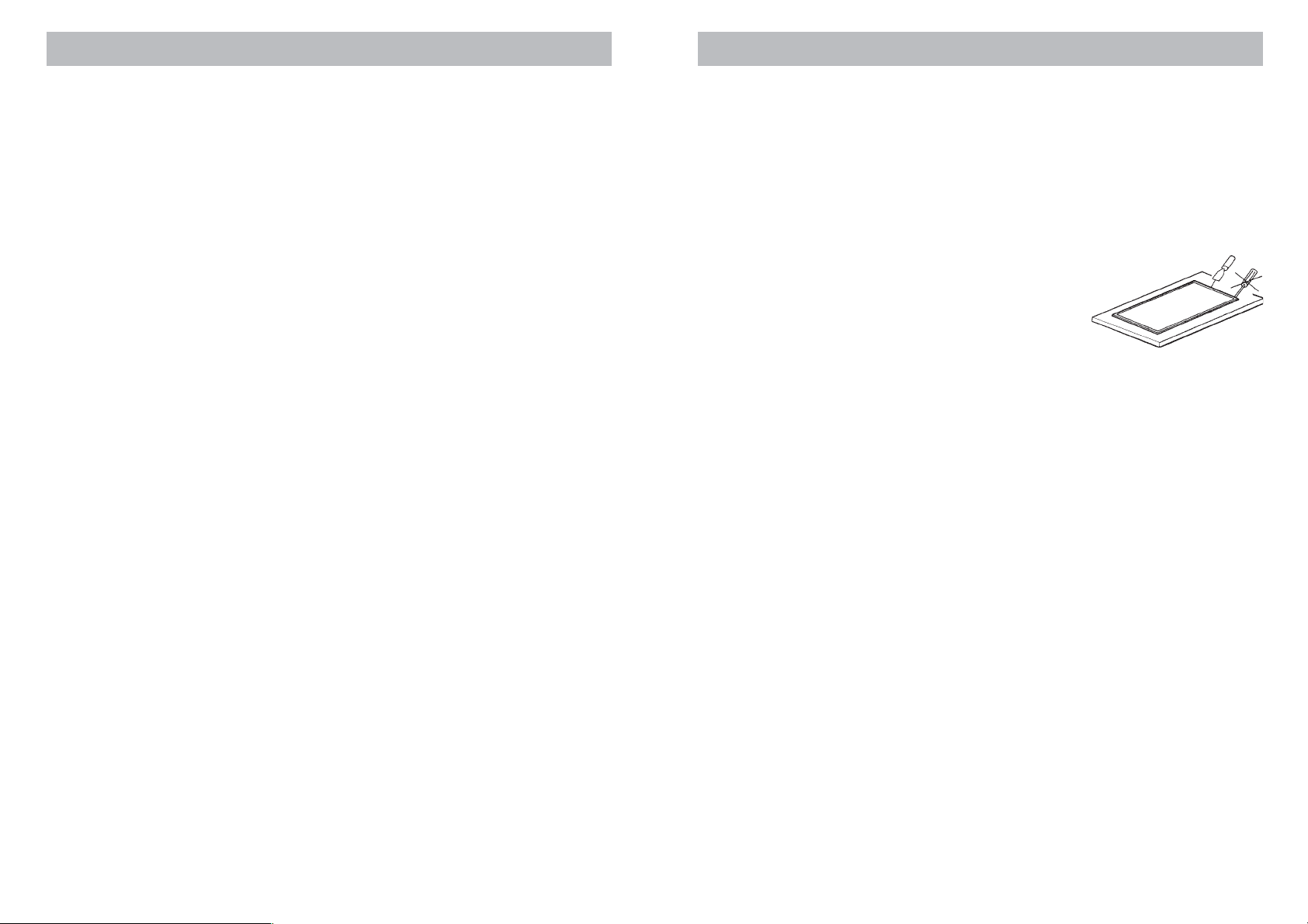
3. Using a flat bladed tool lift the
ceramic top and remove. Store
the ceramic top in a safe place.
To service gas control valves
Access to burner compartments is as per ’to remove the hob’. The
gas control valves are secured to the gas manifold by means of a
clamp fixed via two screws.
1. Remove the screws which secure the gas valve to the gas manifold.
2. Replace the defective part.
3. Replace in reverse order and open isolation valve.
To replace the thermocouple
Access to burner compartments is as per ’to remove the hob’.
1. Remove the retaining ring securing the thermocouple.
2. Remove connection from electronic ignition module.
3. Replace defective part.
4. Replace in reverse order.
To replace the electronic ignition module
Access to burner compartments is as per ’to remove the hob’.
1. Remove the metal cover.
2. Disconnect the leads from the thermocouples.
3. Loosen the 2 securing screws.
4. Replace in reverse order.
a contribution to protecting the environment by disposing of
the packaging appropriately.
To replace internal wiring and the gas control ignition
micro switch
Gas supply
Check that the data plate shows the appliance is suitable for the
available gas supply.
Access to burner compartments is as per ’to remove the hob’.
1. Disconnect wiring between ignition module and gas control.
2. Disconnect microswitch from gas control.
3. Replace in reverse order.
4
21

Maintenance trouble shooting
Important
Only authorised personnel from the Service
Agent are qualified to
work on the main gas and
electric systems.
What’s wrong Possible cause Solution
It is not always necessary to call the Service Agent. In some cases,
you may be able to solve the problem yourself. This table contains
some useful information.
If any of the fault finding procedures below do not rectify the
problem call Sampford & Staff. For contact details refer back page
of this booklet.
...If none of the electrical ❍ Power turned off. ❍ Turn power on.
systems work. ❍ Faulty fuse. ❍ Check the fuse in the main
fuse box and replace if faulty.
❍ The automatic safety ❍ Check the main fuse box to see
switch has been tripped whether the automatic trip
or a fuse has blown. switch or a differential switch
has tripped.
...If the electronic ignition ❍ There may be food or ❍ The gap between the spark
system does not work. cleaning product plug and the burner needs to
particles between the be cleaned carefully.
spark plugs and the
burners.
❍ The burners are wet. ❍ Dry the burner caps carefully.
❍ The burner covers are ❍ Make sure that the burner caps
not located correctly. are correctly located.
...If the flame on the ❍ The burner components ❍ Put the components in their
burners is not evenly have not been correct positions.
distributed. assembled properly.
❍ The gas ports on the ❍ Clean the gas ports on the
burners are dirty. burners.
...If the gas flow does not ❍ The isolation valve is ❍ Open the isolation valve.
seem normal or there closed.
is no gas flow at all. ❍ If the gas is supplied ❍ Replace the gas bottle with a
from a gas bottle, it full one.
may be empty.
...If the kitchen smells ❍ One of the valves has ❍ Check to see if a valve has
of gas. been left open. been left open.
❍ Possible leak on the ❍ Check that the coupling on
gas bottle coupling. the gas bottle is in order.
...If the safety shut off ❍ The control knob was ❍ Once the burner is lit, hold the
device on different not held down long control knob down a few
burners doesn’t work. enough. seconds longer.
❍ The burner ports are ❍ Clean the burner ports.
dirty.
Flames are normally blue and sharply defined. If flames are ever yellowish or noisy or if the gas
does not ignite within the period specified under ‘boiling burner operation’ abnormal operation
is indicated. Call your local Service Agent.
20
Never pour water on
burning fat or oil. Cover
with a damp cloth to
extinguish the fire and
disconnect the cooking
appliance.
Electrical supply
This appliance requires connection to a 10 Amp wall socket.
What to do if you smell gas
❍ Do not try to light the appliance.
❍ Do not touch any electrical switch; do not use a phone in your
building.
❍ Immediately call your gas supplier from a neighbour’s phone.
Follow the gas suppliers’s instructions.
❍ If you cannot reach your gas supplier, call the fire department.
Safety considerations
If the information in this manual is not followed exactly, a fire or
explosion may result causing property damage, personal injury
or death.
❍ Never leave the appliance unattended when cooking with fat
or oil. It could ignite if overheated.
❍ In case of a defect, switch electric power off at the mains.
❍ Never use an appliance that is not working correctly.
❍ Do not allow the flame to extend beyond the edge of the cook-
ing utensil. This instruction is based on safety considerations.
❍ Do not forget that the unit becomes hot when in use. Common
sense is important. Just because the flame is out, does not mean
parts cannot still be hot.
❍ Be sure to disconnect the electrical supply before disassembly
of the appliance.
❍ Keep the appliance area clear and free from combustible ma-
terials, gasoline and other flammable vapours and liquids.
❍ Note: To avoid jeopardising the electrical safety of the appli-
ance, it is forbidden to use high-pressure or steam jet cleaning
devices.
❍ Cabinets installed above the gas cooktop must have a mini-
mum clearance of 650 mm (24”).
❍ Important
When using a very large pot, leave a gap of at least 50 mm
(2”) to avoid damaging any parts in bench top wood, plastic
or other non-heat resistant materials. Never leave oil or hot fat
unattended.
❍ Never place unstable pans or containers on the cooking hob
or burners, as they may accidentally tip over.
❍ Never cover up the slots at the rear of the appliance.
5

Cleaning
DO NOT SPRAY AEROSOLS IN THE VICINITY OF THIS
APPLIANCE WHILE IT IS OPERATION.
WHERE THIS APPLIANCE IS INSTALLED IN A MARINE CRAFT OR
IN CARAVANS, FOR SAFETY REASONS IT SHALL NOT BE USED
AS A SPACE HEATER.
THIS APPLIANCE IS NOT INTENDED FOR THE USE BY YOUNG
CHILDREN OR INFIRM PERSONS WITHOUT SUPERVISION.
YOUNG CHILDREN SHOULD BE SUPERVISED TO ENSURE THEY
DO NOT PLAY WITH THIS APPLIANCE.
WARNING - THE UNDERSIDE OF THIS HOB MAY EXCEED 95˚C.
FIT A TIMBER BARRIER TO THE ENCLOSURE, REFER TO THE INSTALLATION INSTRUCTIONS.
Make sure you keep these instructions for use and assembly in
a safe place, so that you can hand them on with the appliance
if it ever changes owner
Important
Always allow the burner
caps to cool down before
cleaning then.
Clean vinegar, lemon or
tomato juice as soon as
posssible after spillage.
Please clean cooktop thoroughly before first use. Operate boiling burners and wok burners on HIGH for a few minutes to eliminate the ‘new’ smell.
Never use abrasive or caustic cleaners,
oven cleaning sprays or scourers that might
scratch the glass.
Never use sharp objects such as metal
scourers or knives to remove the hardened
remains of food from the ceramic surface
or burner.
Wipe grains of sand and other debree that
may drop from cleaning vegetables and
fruits. These particles will scratch the ceramic surface.
Clean the ceramic cooktop with a sponge
and a mild detergent or soapy water (or
specialist cleaning product) when cooktop
has cooled down completely.
Use a glass scraper for stubborn dirt and
always place it flat to the glass, taking special care not to get it too near to the trim
on the burners.
To keep the burners and pan supports
clean, you must clean them periodically by
washing them in soapy water and brushing them with a non-metallic brush to ensure that the port holes and grooves are
perfectly clean and can provide a perfect
flame. Always dry the burner caps and the
pan supports if they have become wet.
From time to time clean the thermocouple
and the spark igniter with a soft toothbrush.
6
19

Do not Do
Installation instructions
18
Do not use small pans on
large burners. The flames
should never come up the
side of the pan.
Never cook without a lid
or with the lid half off;
you are wasting energy.
Do not use pans with uneven bottoms, as they
make the food take longer
to cook and waste energy.
Do not place a pan on
one side of a burner, as it
could tip over.
Never place pans directly
on top of the burners.
Do not use large pots or
heavy weights which can
bend the pan support or
deflect the flame onto the
hotplate.
Avoid using griddles and
earthen ware pots etc. at
maximum heat for a long
time.
Do not remove the wok
pan support and enclose
the burner with a wok
stand as this will concentrate and deflect heat onto
the hotplate.
Do not place anything,
e.g. flame tamer, asbestos mat, between the pan
and the pan support as
serious damage to the
cooktop may result.
Use only wok support supplied or recommended by
the manufacturer of the
cooktop.
Always use pans that are
suitable for each burner,
so as avoid wasting gas
and discolouring the
pans.
Always place the lid on
the pan. Use pans, frying
pans and casserole dishes
with thick flat bottoms.
Always place the pan
centrally over the burner,
not to one side.
Place the pan on the pan
support. Ensure that the
burner’s pan support and
covers are properly in
place before use.
Handle pans with care
when they are on the
cooking hotplate.
Only use one burner per
pan. For concave vessels
use the supplementary
pan support on the large
wok burner.
Be careful handling the
supplementary pan supports. They are HOT after
use.
Installer instructions
❍ This appliance must be installed in a position with the proper
level of ventilation. Do not obstruct the flow of combustion and
ventilation air.
❍ The gas pressure regulator supplied with the appliance must
be installed in line with the gas pipe. (N.G. only)
❍ Before commencing any work, make sure that the power point
switches are turned off and the three in plug is removed.
❍ If the appliance cannot be adjusted to perform correctly con-
tact Sampford & Staff or the local gas utility. For service contact telephone number refer back page.
❍ Instruct the user in the operation of the appliance before leav-
ing.
❍ For pressure testing in excess of 3.5 kPa (1/2” psig) the appli-
ance and its individual shut-off valve must be disconnected
from the gas supply piping system. For pressure testing of the
gas piping system at test pressures equal to or less than 3.5
kPa (1/2”psig) the appliance must be isolated from the gas
supply system by closing its individual shut off valve during
any pressure testing.
❍ The data plate is attached to the bottom of the unit. A duplicate
copy is supplied at the back of the instruction booklet.
❍ This appliance should not be connected to a combustion prod-
uct evacuation device.
❍ Before installing your new cooktop make sure that the meas-
urements are all correct.
Statutory requirements
This appliance shall be installed in accordance with the manufacturer’s installation instructions, local gas fitting regulations, municipal building codes, electrical wiring regulations, the Installation Code for gas burning appliances, AS 5601 and any other
statutory regulations. Refer to the AGA Installation Code for piping size details.
Overall dimensions
7

Preparing to install
Only an authorised person should connect the appliance.
This built-in cooktop is intended to be inserted in a benchtop cut-
out. For cutout dimension refer figure below.
The small pot trivet is provided as an
additional support for pan diameters
less than 12cm.
Recommended pan diameters
Burner Min Ø of pan Max Ø of pan
Wok burner ≥ 22cm
Large boiling burner 22 cm 26 cm
Medium boiling burners 14 cm 20 cm
Simmer burner 12 cm 14 cm
Cooking recommendations
Very high /High Medium Low
Wok burner Boiling, grilling, Reheating and keeping
browning, and Asian things hot, cooked and
food (wok). pre-cooked dishes.
Large boiling Steaks, omelettes, Rice, white Steaming,
burner frying. sauce and and
ragout. vegetables.
Medium Steaming potatoes, Reheating, keeping
boiling fresh vegetables, things hot and making
burner stews and pasta. tasty casseroles.
Overhead clearances
A range hood fitted above the top must be installed according to
the installation instructions for the range hood. A minimum distance of 650 mm is required for a range hood and 750 mm for an
exhaust fan. Minimum clearance to an overhead cupboard is
600mm.
Side clearances
Simmer Casseroles, rice Defrosting Melting:
burner pudding and and slow butter,
caramels. cooking: chocolate
vegetables and jelly.
fruits and
frozen
products.
If the distance measured from the periphery of the nearest burner
to any vertical surface is less than 200 mm, the surface shall be
protected in accordance with clauses 5.12.1.1 & 5.12.1.2 of AS
5601.
Bottom clearance and heat barrier
Leave a space of at least 10mm between any drawer partition that
is installed underneath the cooktop.
8
17

Wok burner assembly
To assemble the wok burner and pan support place the burner
body onto the burner skirt and the burner head onto the burner
body so the anti-twisting lip fits into the notch in each case.
It is important that these parts are assembled in the correct
position. The cooktop may otherwise not function correctly or
might be damaged.
Wok burner operation
The wok control has 4 settings.
Largest flame = The outer and inner burners are both
operating on high flame.
Large flame = The outer burner burns low and the
inner burner burns high.
Small flame = Only the inner burner burns high.
Smallest flame = Only the inner burner burns low.
For ongoing cooking a variable setting between the flame sizes
can be used.
Ventilation requirements
The use of a cooktop produces heat and moisture in the kitchen.
For this reason make sure that the room is properly ventilated.
Keep natural ventilation openings, such as windows, open or
provide a mechanical ventilation device (e.g. a range hood or
overhead exhaust fan).
Additional pan supports
The wok burner is supplied with an additional pan support for pans larger than
26mm diameter, i.e. roasting dishes, earthenware pots and woks, etc.
Benchtop specification
This cooktop can be fitted to a benchtop of 18 - 30mm thickness.
Special considerations for installation over under bench
oven
If installing the cooktop over an under bench oven and connecting
the cooktop via a hose assembly, ensure that the hose assembly is
retained from accidental contact with the flue outlet of the under
bench oven.
Installation procedure
Before connecting the unit, check whether the local connection
conditions (type of gas) are compatible with the unit’s settings. The
model number, type of appliance, gas pressure, gas type, injector
size and total hourly gas consumption are noted on the data plate
attached to the underside of the cooktop base. A duplicate of this
data plate is at the rear of this booklet.
Observe any special conditions imposed by local suppliers (utilities).
1. For cutout dimensions and clearances refer drawing on previous page. Observe the minimum insertion gap. DANGER! combustion may be affected.
2. Slightly loosen the retaining
screws of the 4 clamping brackets positioned at the bottom of
the cooktop.
3. Insert the cooktop into the bench
cutout.
4. After insertion, from below, swivel the clamp brackets 90° and
tighten them against the bottom of the benchtop.
Electrical connection
An electrical 10 amp socket needs to be within 1 m of the hotplate
to allow electrical connection. The socket must remain accessible
after installation of the appliance.
Important note:
This appliance is connected to the mains (240 VAC) by means of
the connecting lead which must be fixed to the kitchen unit to prevent it from coming into contact with hot parts of the hob (or an
oven installed underneath) and remain accessible after installation of the cooktop.
16
9

10
When connecting the cooktop ensure that the earth wire is connected first and that all wires are connected to the correct terminals.
Gas connection:
The cooktop is adjusted to operate on the gas type specified on
the gas type label located on the
bottom of the unit. If in doubt as to
type of gas available contact the
network operator or gas supplier for
confirmation of gas type.
The cooktop must be connected to
the gas supply with upstream connection of an isolation valve in accordance with the respectively valid regulations. We recommend
that the isolation valve be fitted prior to the cooktop to enable
isolation of cooktop from gas supply. The valve must be easily
accessible at all times.
This appliance may be connected with a hose assembly, class B or
class D. If connected with a hose assembly ensure that the supply
connection point is accessible with the appliance installed.
The position of the inlet connection is measured from bottom RH
rear of unit, 45mm centre line from rear and 27mm centre line for
RH side.
1. Remove plastic cap from gas supply line prior to installation.
2. Fit regulator (N.G.) or Propane fitting (Propane) directly to the
R1/2” connection. Direction of gas flow is indicated on the
rear of the regulator.
Natural gas connection Propane gas connection
Burner location and control panel
The cooktop consists of a ceramic top fitted with four boiling burners and one wok burner. All burners are fitted with electronic ignition and safety shut off device.
1. Wok burner 4. Medium boiling burner
2. Small boiling burner 5. Medium boiling burner
3. Large boiling burner 6. 5 control knobs
Boiling burners operation and ignition
The boiling burners have two heat settings.
Large flame = highest setting
Small flame = lowest (simmer) setting
The highest flame setting is used for initial
boiling. For ongoing cooking a variable
setting between high and low flame can
be made.
To activate the burner depress the control
knob and turn to ‘high flame’ position.
Keep knob depressed for approx. 6-7 seconds to allow the safety
shut off to activate. The flame will extinguish if the knob is released
too soon.
If ignition fails depress knob and try again. If flame is not established in 15 seconds release the control knob and open a door and
wait 1 minute before attempting a new ignition procedure.
If the burner flames are extinguished - for whatever reason - turn
OFF the control knob and wait at least one minute before retrying
to ignite the burner.
Ensure that the flames do not extinguish when you reduce to low
flame quickly.
To turn off the gas supply to a burner return the control knob to the
‘OFF’ position.
15

User instructions
In the event of a fault
disconnect the electrical
power to the cooktop
and shut off the gas
supply.
Contact your local gas
supplier or service
agent. The service
agent contact details
are at the rear of this
booklet.
14
Important information
The top plate of the cooktop consists of a very resistant ceramic
and with proper handling will stand up to all household stresses.
Before using the cooktop for the first time, please read the following practical tips.
❍ This appliance is intended for domestic use only
❍ Do not use the ceramic top as a work surface or storage space.
❍ Do not let pans with rough or textured bottom surfaces rest on
the ceramic top. They can cause scratching when moved around
on the top.
❍ Do not drop hard or sharp objects onto the top. This may dam-
age it.
❍ Never use two burners to heat one single receptacle.
❍ The cooktop must be switched off immediately if the ceramic
top develops any cracks, splits or fractures. If this should happen, switch off the power and gas supply.
❍ Do not use the cooktop to heat a room.
❍ Never prepare food in aluminium foil or plastic containers on
the hob. The material melts on.
❍ Melted-on sugar or food containing sugar should be cleaned
off immediately using a glass scraper, otherwise they could
cause damage to the ceramic surface.
❍ The surfaces of the cooktop, trivets and burners will become
hot during operation. Small children must be kept at a safe
distance from the appliance.
❍ Do not use large-diameter pans on the burners nearest to the
control knobs, as the flames might reach them, making them so
hot that they could cause injury.
❍ Grease and oils are flammable if overheated. Always stay near
the oven when preparing food using grease and oil, e.g. french
fries.
❍ Never cover the ventilation openings at the rear of the cooktop,
e.g. with a tea towel.
❍ Only ignite the gas burners when all the burner components
are correctly assembled.
❍ Never flambe dishes while using a range hood or extractor
fan. The flames could set the range hood or extractor fan on
fire.
❍ Leads from electrical appliances must not touch the cooktop.
They will melt on and the cable insulation will be damaged.
❍ Always watch pressure cookers until they reach the correct pres-
sure. You should first set the burner to highest level and reduce
the heat when the required pressure has been reached.
3. Check for gas soundness at connections. NEVER use a naked
flame to check for leaks.
4. Check correct operation of each burner individually and in
combination. Burner flames should be clear blue, with no yellow tipping. If the burners show any abnormality check that
burner heads are correctly located and refer to the ‘maintenance trouble shooting’ chart on page 20. If satisfactory performance can not be obtained, contact Sampford & Staff or
the local gas utility. For service contact number refer back page
of this booklet.
Note: These burners have no aeration adjustment.
It should be expressly noted that we cannot accept any liability for
direct or indirect damage caused by wrong connection or improper
installation. When being repaired, the appliance must always be
disconnected from the main gas and electricity supply; if required,
notify our customer service.
Energy consumption
Natural Gas (1kPa)
Burner Main Turndown Hourly gas
injector size injector size consumption
(mm) (mm) (MJ/hr)
Left Front 1.30 0.68 8.10
Left Rear 0.97 0.98 4.80
Right Front 1.30 0.68 8.10
Right Rear 1.57 0.85 11.60
Wok- outer ring burner 2.15 1.30 22.00
Wok - inner burner spud size 0.65 1.70
Propane Gas (2.75 kPa)
Burner Main Turndown Hourly gas
injector size injector size consumption
(mm) (mm) (MJ/hr)
Left Front 0.70 0.68 6.00
Left Rear 0.53 0.98 3.50
Right Front 0.70 0.68 6.00
Right Rear 0.83 0.85 8.50
Wok- outer ring burner 1.12 1.30 17.20
Wok - inner burner spud size 0.31 1.10
11

Gas conversion instructions
Converting the cooktop from Natural Gas to Propane Gas can
only be carried out by an authorised person.
Boiling burners main injector conversion
Request change-over injectors from our customer service department (refer injector charts on previous page for sizes).
Before conversion the cooktop must be disconnected from the electricity and gas valves must be turned to the OFF position.
1 Remove the pan supports, 5 control knobs and anti-spillage
gaskets, burner caps and burner heads.
2. Conversion of main and turndown injectors requires the removal of the ceramic top. Use a flat bladed tool to lift the ceramic frame and remove. Store ceramic top in a safe position.
3 Change the injectors using a 7-mm socket wrench and be sure
to tighten them down properly so that they are fully airtight.
NOTE: it is not necessary to adjust the primary air control on these
burners.
Boiling burners turndown injector conversion
1. Undo burner burner heads fastening screws and remove boiling burner heads.
2. Disassemble wok pan supports and burner head. Undo the
three fastening screws and remove wok burner body.
.
3 Remove ceramic cooktop.
4 The turndown injector is incorporated in the gas tap as indi-
cated in figure above. Use a small screw driver to rotate anticlockwise to closed position.
5. Reassemble parts in reverse order. For replacement of wok
burner refer to adjacent figure.
Outer wok burner main injector conversion
1. Disassemble the wok burner pan supports and wok burner as
indicated in figure at left
2. Undo 3 wok burner head fastening screws and remove burner
head.
3. Unscrew and remove boiling burner heads.
4. Remove ceramic top. Refer previous page.
5. The main injector block is fixed to the throat of the mixing
tube. Use a size 10 spanner to unscrew the injector. At the
same time hold the injector block with a
size 13 spanner to anchor the connection
against movement.
6. Replace with relevant injector according
to the injector chart.
7. To adjust aeration release the locking screw
and shift the aeration sleeve 11mm for
Natural Gas or 12mm for Propane Gas.
(Refer ‘X’ dimension in figure).
Inner wok burner main injector conversion
1. Using a size 8 spanner unscrew fitting 3 from injector block 2
as indicated in figure below. At the same time hold the injector
block with a size 12 spanner to anchor the connection against
movement.
2. Remove the injector spud (4) and replace with relevant sized
spud according to the injector chart.
3. Aeration is provided by 2 circular holes (6). Leave in the fully
open position
4. Tighten all parts and check for
gas soundness before replacing
the ceramic top. Reassemble the
cooktop in reverse order.
5. Adhere the data plate for the
replacement injectors on top of
the previously valid data plate.
6. Check for flame stability by
turning the control knobs a few
times from large to small flame
whilst the burners are ignited.
The flames should not extinguish.
12
13
 Loading...