

Nedap N V XQMK2 Installation manual

manual
XQ MK2 Electronics
Januari, 2010
PRELIMINARY
Metal Detection Settings Only
- 1 -
Technical Support
E-Mail : support-rs@nedap.com
Safety precautions
CAUTION - RISK OF ELECTRIC SHOCK - DO NOT OPEN
CAUTION: TO REDUCE THE RISK OF ELECTRICAL SHOCK, DO NOT REMOVE COVER (OR BACK). NO USERSERVICEABLE PARTS INSIDE. REFER SERVICING TO QUALIFIED NEDAP SERVICE PERSONNEL.
Lightning ash with an arrowhead, enclosed in a triangle, alerts you to the presence of uninsulated
voltage points inside the product which could cause a serious electrical shock.
An exclamation mark enclosed in a triangle alerts you to important operating and maintenance instructions in the documentation provided with the product.
WARNING! To avoid the risk of re or electrical shock, never expose these products to water or operate in a high humidity environment.
EN 50419:2005 This European Standard species a marking
• of electrical and electronic equipment in accordance with Article 11(2) of Directive 2002/96/EC
(WEEE); This is in addition to the marking requirement in Article 10(3) of this Directive which
requires producers to mark electrical and electronic equipment put on the market after 13 August
2005 with a ‘crossed-out wheeled bin’ symbol.
• that applies to electrical and electronic equipment falling under Annex IA of Directive 2002/96/
EN 50419:2005
EC, provided the equipment concerned is not part of another type of equipment that does not fall
within the scope of this Directive. Annex IB of Directive 2002/96/EC contains an indicative list of
the products, which fall under the categories set out in Annex IA of this Directive;
• that serves to clearly identify the producer of the equipment and that the equipment has been put
on the market after 13 August 2005.
© 2009 Nedap Retail Support Netherlands Parallelweg 2d, 7141 DC Groenlo
The software / hardware described in this book / le is furnished under a license agreement and may be used only in accordance with the terms of the agreement.
Documentation version Manual XQ MK2 2010 1 PRELIMINARY
Copyright Notice
All Rights Reserved. Any technical documentation that is made available by Nedap Retail Support is the copyrighted work of Nedap Retail Support and is owned by Nedap Retail Support.
No warranty The technical documentation is being delivered to you and Nedap Retail Support makes no warranty as to its accuracy or use. Any use of the technical documentation or
the information contained therein is at the risk of the user. Documentation may include technical or other inaccuracies or typographical errors Nedap Retail Support the right to make
changes without prior notice. No part of this publication may be copied without the express written permission of Nedap Retail Support, Parallelweg 2d, 7141 DC Groenlo, Netherlands
Trademarks Nedap, the Nedap logo, Nedap EASi/Net and the Nedap EASi/Net are registered trademarks of Nedap N.V. Groenlo.
Other product names mentioned in this manual may be trademarks or registered trademarks of their respective companies and are hereby acknowledged.
- 2 -
Digital Printed in the Netherlands

Table of Contents
2 Technical Support
2 Safety precautions
2 Copyright Notice
4 1. Introduction
4 1.1 XQ MK2 RX (R2)
4 1.2 XQ MK2 Tx (T2)
4 1.3 | 4 Watt transmitter
5 1.3.1 Aisle Improvement Module
5 1.4 New Attenuator
5 1.5 Performance Indicator
6 2. Block diagrams
6 2.1 Network communication and
sync
6 2.1.1 Hand-terminal-connection
15 2 antennas XQ MK2 congura
tion
16 3 antennas XQ MK2 congura
tion
16 4 antennas XQ MK2 congura
tion
17 5 antennas XQ MK2 congura
tion
17 6 antennas XQ MK2 congura
tion
17 7 antennas XQ MK2 congura
tion
18 8 antennas XQ MK2 congura
tion
18 9 antennas XQ MK2 congura
tion
19 10 antennas XQ MK2 congura
tion
24 8.2.3 Sync Period
24 8.2.4 Sync Voltage
24 8.2.5 Frequency
24 8.2.6 Gain
24 8.2.7 Coupling
25 8.3 R2 Alarm
25 8.3.1 Alarm
25 8.3.2 Blocked
25 8.3.3 Sensitivity
25 8.3.4 Threshold
25 8.3.5 Noise level
25 8.3.6 Signal Level
25 8.3.7 Adjusting receiver settings
26 8.4 R2 Scope
27 9. Specications X2
(K100)
7 2.1.2 Data communication over
coax
7 2.2 Transmitter
7 2.2.1 Anti-deactivation regulation
7 2.2.2 Output multiplexer
7 2.2.3 Tx output power setting
8 2.3 Receiver
8 2.3.1 Input multiplexer
8 2.3.4 Processor
9 2.3.5 Customer counting
9 2.3.6 Test-connectors
9 2.4 Dummy loads
10 3. PCB Components overview
10 3.1 Connector overview XQ TX
19 11-16 antennas XQ MK2 congu
ration
20 30 antennas XQ MK2 congura
tion
21 7. Conguration Manager
22 8. Metal Detection
22 8.1 T2 settings
22 8.1.1 Tx Enable
22 8.1.2 Applicatien Version
22 8.1.3 Bootloader version
22 8.1.4 Sync Period
22 8.1.5 Frequency
22 8.1.6 Current
22 8.1.7 Power
23 8.1.8 Adjusting the transmitter
settings
12 3.2 Connector overview XQ RX
14 4. Unit address
14 5. Connection to PC / Laptop
15 6. Networking with NCC MK2
15 Overview of necessary NCC’s
24 8.2 R2 Settings
24 8.2.1 RxEnable
24 8.2.1 Applicatien Version
24 8.2.2 Bootloader version
- 3 -
1. Introduction
The XQ MK2 Units are the successors of the XQ series internal OS/T electronics. The complete redesign has many new
features:
• Powerful transmitter (4 watt)
• Attenuator setting can be done for every aisle separately
• Attenuation jumpers are replaced by a rmware setting
• Integral customer counting
• Integral Metal detection, fully (remote) congurable with OS/T congurator
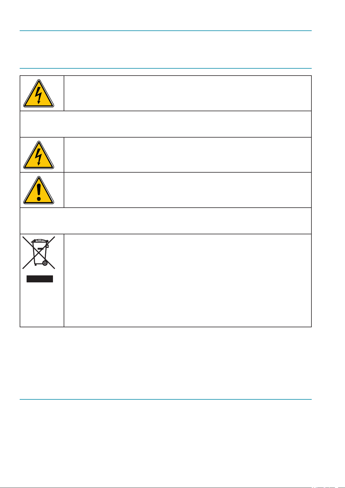
1.1 XQ MK2 RX (R2)
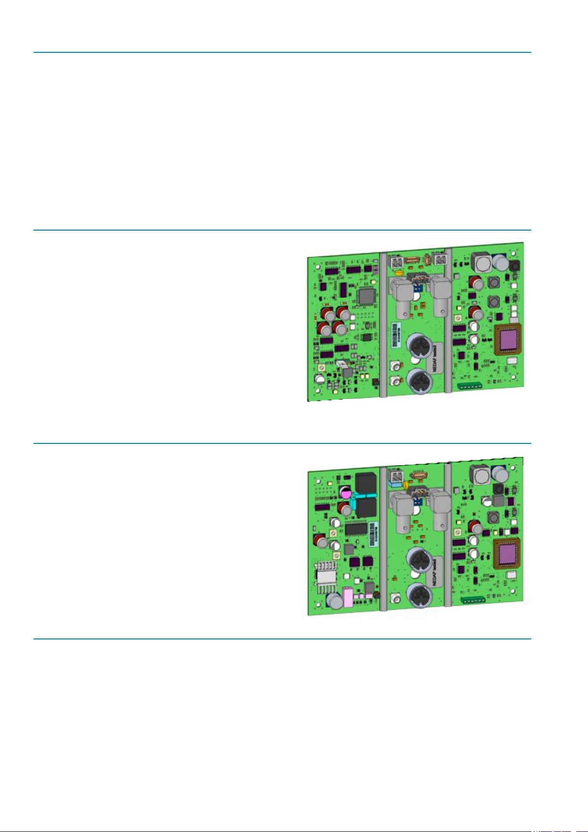
1.2 XQ MK2 Tx (T2)
The Tx units come with a 4 watt transmitter, which can be
switched on with a special functionality module.
1.3 | 4 Watt transmitter
The advantages of the new transmitter are:
• Aisle width between panels can be proximally 10 % more for the same label
OR
• Distance between the panels will be the same and smaller labels can be used
OR
• To suppress interference from other systems
- 4 -

In combination with an AIM module (Aisle Improvement Module) the full features of the transmitter can be used.
1.3.1 The AIM (Aisle Improvement Module)
The module increases the power up to 4Watt.
All antennas suitable for the XQ Mk2 internal units with metal detection will be suitable for 4 Watt (effective power). The
outside of the antenna will be marked with a ‘4W’ addition to the serial label. Inside the antenna the will be a label
“Suitable for 4 W “
1.4 New Attenuator
The advantages for the attenuator are:
• Easy installation
• Additional external attenuators are not necessary anymore
• Hardware jumper settings are replaced through software settings
• Useful for aisles with different aisle width, example system with 2 aisles
• First aisle width is 1.60 meters
• Second aisle width is 1.00 meters
1.5 Performance Indicator
Firmware version 1.8xx and up contains performance indicators. This means that it is possible to actually trace the delivered
system performance.
A Nedap EAS system contains several different signal processing functions, which are mapped to several different hardware
units. For example we have a power supply, a sweep generator, a transmitter, a receiver, and deactivation units. To moni-
tor the performance of the system from bird’s eye view we have to look at and integrate all performance indicators of each
comprising unit. The actual data integration is done off line, in the TOPserver and or Easinet.
For all OST units we need performance indicators:
1. Performance indicator for a power supply.
A measure which indicates in time the actual delivery of good power. In practice as long as the system is working the
power is considered to be good. So this performance is not separately monitored. System uptime is used as indicator.
2. Performance indicator for a sweep generator.
A measure which indicates in time the actual delivery of good sweeps to the system. In practice as long as the system is
working the sweep generator is considered to be good. This performance is not separately monitored. System uptime is
used as indicator.
3. Performance indicator for transmitters.
A measure which indicates in time the actual delivery of good sweeps to the transmitter panel. Interruptions of the
power delivery due to AGC actions are monitored. This is a new performance indicator.
4. Performance indicator for receivers.
A measure which indicates in time the actual reception of clean sweeps from the panel. This is not explicitly monitored.
And a measure which indicates in times the actual level of external noise. This level must contain all detection prohibit-
- 5 -

ing signals. This signal is monitored. This is the second new performance indicator.
With these performance indicators it should be possible to monitor accurately the performance of the system. These
indicators cover the primary detection function. Also the communication is checked continuously of course.
Altogether it is expected that the most frequent occurring disturbances and failures are covered. Some mechanical
failures are not covered, like receiver antennae wire failures. To cover these type of events it is sufcient to look at the
occurrence of label detection events at all. If alarm events occurs one can safely assume that the system is not dead yet.
The most important feature is the logging of EAS detection performance over time. Covered events are downtime due
to power outages, loss of transmit signal due to AGC events, occurrence of alarms, and environmental noise which
degrades the detection performance’s. Of course it is not possible to distinguish between false alarms and true label
alarms, because if that would be possible then all false alarms could be eliminated beforehand.
5. Performance indicator for standalone label deactivation units.
A measure which indicates in time:
• the actual delivery of good power
• the actual delivery of good sweeps to the system
• the actual delivery of good sweeps to the antenna
These parameters are covered by the system uptime indicator.
• the actual reception of clean sweeps from the panel
This parameter is monitored by the receiver (type) performance indicator.
2. Block diagrams
The XQ MK2 Transmitter with integral customer counting and metal detection.
2.1 Network communication and sync
The XQ units are slave-only, they need an RF signal originating from a master output . This could be an NCC, SQ unit or
TDC unit. The RF signal has a frequency of four times 8.2 MHz and sweeps between 30.... 36 MHz.
The RF signal is used to drive the transmitters as well as the receivers. The Coaxial cable between master-output and slave
input is also used to distribute DC power and data-communication
2.1.1 Hand-terminal-connection (K100)
A standard NEDAP RS handheld terminal (HT) may be connected to connector K100. With this HT you can edit the various
local settings. With this terminal all digital settings can be made, even if the network is nonfunctional.
Some settings can only be adjusted by using an OS/T Conguration Manager
Especially the Metal detection settings are only possible with the congurator
- 6 -

2.1.2 data communication over coax
One of the important features from the OS/T system is the data-com over the coax-cable. With this feature it’s no longer
necessary to use an extra data-cable between the units, which simplies the installation of the system. All the connected
units are interrogated periodically by the master. If there are messages like an alarm on a connected Rx unit, then the mas-
ter unit will process this and takes the necessary action: Sending a command to turn on the lamps on the activated aisle.
The XQ MK2 unit has two slave-sync connectors (K101 and K102) from which the unit can be driven from a NCC-4, SQ, or
TDC unit. DC supply is from the sync-connectors.
2.2 Transmitter
The Transmitter generates an 8.2 MHz RF signal with a maximum power level of 4 Watt to feed the transmitter antenna.
The transmitter receives its RF reference signal and conguration data from the local communication control section.
The start-pulse is distributed as a 1 microsecond break of the RF signal (32 periods) and indicates the start of the 1.6 ms
sweep. All timing of the OS/T-system is related to this start-pulse.
The RF signal (with a 30 till 36 MHz sweep) for the power amplier is divided by for 4 to create the 8.2 MHz transmitter sig-
nal. The power amplier consists of a class D MOSFET driver stage. The square wave output is ltered to achieve a cleaner
carrier. The 50 ohm output impedance is regulated by measuring output current and output voltage and adjusting the drive
signal of the MOSFET power stage accordingly. These two output parameters are measured with a current transformer and
a capacitive voltage divider circuit at the output stage. From these signals a phase control signal and the amplitude control
signal are derived. Both signals can be seen on the test connector. The signals are the feedback to the driver stage.
2.2.1 anti-deactivation regulation
If a RF label comes close to the antenna, it could be deactivated by the transmitter eld. To prevent this phenomenon a tag
detection circuit is used. A tag close to the antenna can be detected by looking at the antenna signal. A resonating tag in
proximity causes a small phase-disturbance in the antenna impedance, which can be seen on the phase control signal of the
transmitter. When in a sweep a tag pulse is found the processor can reduce the transmit power in the next sweep to prevent
deactivation of the tag. After the tag signal disappeared the transmit power is gradually increased to the desired power level.
2.2.2 output multiplexer
The transmitter can feed one antenna. The RF signal is switched during the y-back period of the RF sweep. The multiplexer
is a 1 out of 2 type build with PIN diodes. In the y-back-period the antenna is switched off.
The second output of the multiplexer goes to an internal dummy load. This is used for multiplexing when more than one
aisle is used. The “unused” phases can be dumped in the dummyload.
The antenna-output has his own lamp-control-circuit and can be switched on or off individually. The lamps are controlled
by software. The outputs have open, overload and short-circuit detection. These signals are under processor control.
The lamp control circuit is also used for driving the new-style (two-wire) buzzer.
2.2.3 tx output power setting
- 7 -

Default power setting is 2 Watts. This is suitable for almost every situation. With large aisle withs (2 meters or more) it can
be usefull to increase the power to 4 watts.
2.3 Receiver
The Receiver detects the tag signals generated by tags in the aisle formed by a transmitter panel and a receiver panel. Even
very small signals can be detected to achieve a very high pick rate. Aided by heavy use of digital signal processing the false
alarm rate is very low, even under difcult noise conditions. The receiver receives its RF reference signal and conguration
data from the local communication control section.
The antenna is connected to K202. Every sweep the antenna canl be connected to the receiver. This is done in the multiplex-
er circuit. After the multiplexer an attenuation stage can be used to reduce the level of direct feed through in case of very
close antenna distance. The attenuator can be selected as 0, -6dB, -12dB and -18dB. The setting is possible with the hand
terminal (under the sensitivity menu) or with the OS/T Conguration Manager.
A new feature is the possibility to set the attenuator per phase. The reference RF signal is split in four phases and fed to two
mixers together with antenna input. Each mixer generates a LF signal which is ltered, amplied and muted in the y back
period of the RF carrier. The mute circuitry consists of several stages which are controlled by software. The mixers are fed
with 90 degrees phase shift. The resulting LF signals are further processed by the digital signal processor (DSP).
The DSP uses digital memory to store the past quarter of a second to compare different sweeps and improve on noise level
and other unwanted signals components. The ltered signal after processing can be seen on the scope by looking at the
DAC signal.
2.3.1 input multiplexer
The receiver can process two antenna signals. This means that at most 2 antennas can be connected. The antenna signal
is switched during the y back period of the RF sweep. The multiplexer is a 1 out of 2 type build with PIN diodes. In the y
back period all antennas are switched off.
Antenna input 1 (K202) has his own lamp control circuit and can be switched on or off individually. The lamps are controlled
by software. The outputs have an open, overload, and short circuit detection. These signals are under processor control.
The secondairy antenna input (K201) is only meant for oor antennas and has no lamp/buzzer functionality.
2.3.4 processor
The XQ MK2 series boards (Tx and Rx) have only one processor for RX, TX and Communication control.
The processor has several different tasks. It must maintain the status of the transmitter and receiver and controls several
functions:
• lamp detection
• lamp/lamp overload
• multiplexer
• data communication
• handheld terminal communication
• customer-counting 1x2 inputs
- 8 -

• metal detection
All the processor software and all the settings (including the network address) are contained in ash memory. Software is
downloadable in runtime. A new version can be distributed over the network. After downloading, ashing and verifying a
new version the unit resets and is operational again. This can be done remotely.
2.3.5 customer counting
The XQ MK2 PCB has customer counting on board. Two sensors can be connected to monitor the entrance with direction
sensitivity.
The passage between sensors is shaped and buffered and processed by the processor. In this way incoming and outgoing
label alarms can be counted for separately.
The sensor power output is 12 V dc. It is possible to connect sensor with positive or negative going output signals.
2.3.6 test-connectors
K200: The receiver test-connector shows 3 analogue signals to aid in installing and servicing the receiver section. For easy
external triggering a start pulse is available.
The transmitter test connector shows the analogue signals needed to align and verify the transmitter.
2.4 Dummy loads
Dummy loads are no longer needed for the XQ MK2 PCB’s. Unused channels will be programmed as channel “0”.
- 9 -
 Loading...