

Page 1
September 19, 2002 Part no : 9875220
This information is furnished for guidance, and with no guarantee as to its accuracy or completeness; its publication conveys no license
under any patent or other right, nor does the publisher assume liability for any consequence of its use; specifications and availability of
goods mentioned in it are subject to change without notice; it is not to be reproduced in any way, in whole or in part, without the written
consent of the publisher.
TRANSIT-USA
INSTALLATION GUIDE
(For Extended and PS-270 versions)
Page 2

Version: 1.0, September 19, 2002 1 – Introduction.
© Nederlandsche Apparatenfabriek N.V. (IDEAS- AVI)
Parallelweg 2E
P.O. Box 103
NL - 7140 AC Groenlo
FCC ID : CGD TRANSIT
The device complies with part 15
of the FCC rules. Operation is
subject to the following conditions:
(1) This device may not cause
harmful interference, and (2) this
device must accept any interference
that may cause undesired
operation.
The products described in this document may be subject to modifications without corresponding updating of the document.
© Copyright 2002 Nederlandsche Apparatenfabriek N.V. (IDEAS- AVI)
© NEDAP IDEAS – AVI P.O. Box 103, NL-7140 AC GROENLO Page 2-41
Page 3

Version: 1.0, September 19, 2002 1 – Introduction.
Contents
1 INTRODUCTION................................................................................................................................................................4
1.1 Characteristics................................................................................................................................................................4
1.2 Versions..........................................................................................................................................................................5
1.3 Safety precautions. ........................................................................................................................................................6
2 INSTALLATION............................................................................................................................................................7
2.1 Installation...................................................................................................................................................................... 7
2.2 Basic connections.......................................................................................................................................................... 8
2.3 Transceiver unit DIP-switch settings and indications and adjustments. ...........................................................11
2.4 PS-270 connections, U-link & DIP-switch settings and indications. .................................................................14
2.5 Optional NX-500 board, TRANSIT Extended only........................................................................................... 22
3 COMMUNICATION INTERFACES. .................................................................................................................................25
3.1 Connections to inductive readers.............................................................................................................................25
3.2 Connections via the special code emulation outputs. ...........................................................................................25
3.3 Removing the optional communication boards.....................................................................................................25
3.4 RS 232 (RS 232 III, Art. No.: 7806434)..................................................................................................................26
3.5 RS 422 (CM-422, Art. No.: 7811730)...................................................................................................................... 27
3.6 Universal thin server. ( Art. No.: 7806434 ) ........................................................................................................... 28
3.7 Profibus DP (Art. No: 7817134)..............................................................................................................................29
4 APPLICATION INFORMATION ...........................................................................................................................30
4.1 Available embedded software. ..................................................................................................................................30
4.2 Coverage area...............................................................................................................................................................30
4.3 Speed limitations. ........................................................................................................................................................ 31
4.4 Using more systems at the same location. ..............................................................................................................31
4.5 Read range control TRANSIT-SUB. (Art. 7800150)............................................................................................32
4.6 Typical situations.........................................................................................................................................................34
4.7 Typical configurations................................................................................................................................................39
© NEDAP IDEAS – AVI P.O. Box 103, NL-7140 AC GROENLO Page 3-41
Page 4

Version: 1.0, September 19, 2002 1 – Introduction.
1 Introduction.
A high level of performance, security, reliability and convenience is required in various control and monitoring
systems. TRANSIT
a broad range of tags in all environmental conditions.
TRANSIT
is based on proven microwave technology in the 2.45 GHz ISM band and allows identification of
tags at a distance up to 10 meters, even at high speeding passage. The NEDAP TRANSIT
frequency identification equipment using modulated backscatter. In this method, the tags send there code to the
reader by modulating and reflecting the signal transmitted by the reader. To reduce the influence of unwanted
reflections, NEDAP applied circular polarization, which also allows orientation freedom of the tags.
TRANSIT
combines microwave identification and inductive identification in one unit. The system has the
possibility to identify vehicle and persons caring NEDAP XS-cards. For this purpose a small inductive antenna
can be connected to the reader. (Reflex-130) The combination of the small inductive antenna with TRANSIT
called the Gate-Master
TRANSIT
system has a wide range of tags for various applications. Lithium batteries energize the tag circuit,
which gives lifetimes up to 10 years. Heavy-duty tag is developed for vehicle applications. The Window-tags can
be mounted easily behind the windshield of a vehicle. The Booster-unit is a special Window-tag that can hold a
NEDAP inductive identification card. The booster reads this card after activation by the driver. The information
from the card is then transmitted to the microwave reader.
Combi-booster is a combination of the Window-tag and the Booster-unit, which makes the identification of
driver and vehicle possible. Pocket-tag is a microwave tag intended for the identification of people on large
distances.
1.1 Characteristics.
The TRANSIT
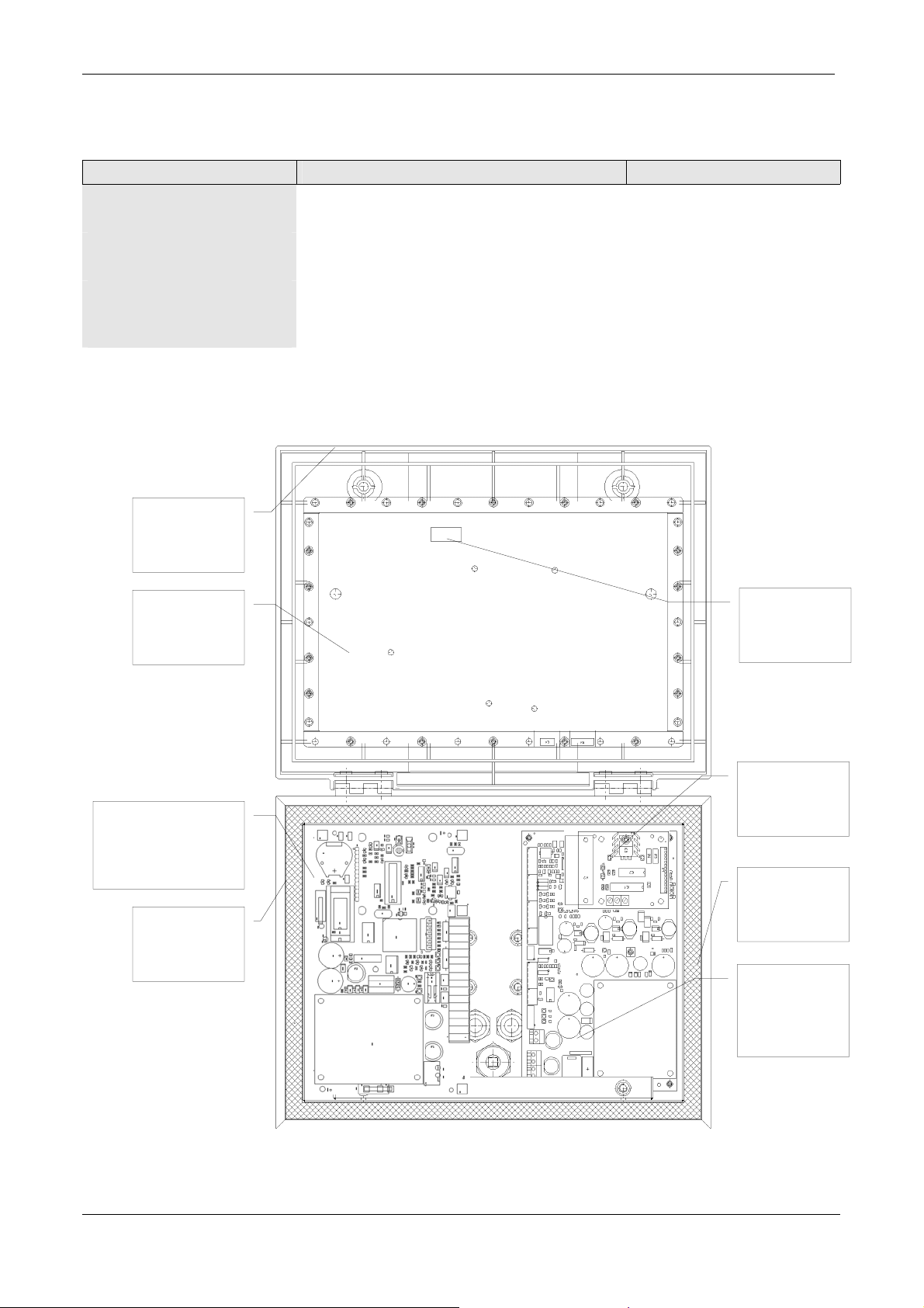
snake eye screws in the cover using a special tool can open this cover. After opening the unit the major
components of the system are becoming visible. In the cover the Transceiver-unit is located, on the bottom of
the stainless steel housing the Power-supply-unit is located. On the Power-supply-unit one of the optional
communication boards can be placed. The backside of the unit hosts three PG-adapters respectively two PG-9,
to be used for data communication cables, and one PG-13 adapter to be used for Mains connections.
is a long-range automatic identification system. The TRANSIT reader communicates with
system features radio
function. Special firmware will be needed see par 3.1
consists out of stainless steel housing, covered by a synthetic material cover. Removing the two
is
PG-adapters
for mains and
data
© NEDAP IDEAS – AVI P.O. Box 103, NL-7140 AC GROENLO Page 4-41
Page 5
Version: 1.0, September 19, 2002 1 – Introduction.
1.2 Versions.
Version Description Article number.
TRANSIT 120 Vac USA
PS-270
TRANSIT 120 Vac USA
Extended PS-270
Special version with PS-270 for parking systems 9875220
Extended version of TRANSIT for access
t.b.d.
control systems and parking systems.
Opened
Cover
Transceiver
unit
Optional NX-500
SimpleXS board.
Trans-IT Extended
ONLY
Stainless steel
housing
Frequency-
select DIP
switches
Location
optional com.
Board
Rubber seal
Power supply
unit PS-270
© NEDAP IDEAS – AVI P.O. Box 103, NL-7140 AC GROENLO Page 5-41
Page 6
Version: 1.0, September 19, 2002 1 – Introduction.
1.3 Safety precautions.
The following safety precautions shall be observed during normal use, service and repair.
• The TRANSIT shall be connected to safety ground.
• Disconnecting from main power supply before removing any parts.
• The TRANSIT shall only be installed and serviced by qualified personnel
• To be sure of safety, do not modify or add anything other than mentioned in this manual or indicated by
NEDAP NV.
• Replace fuses only with the same type and rating.
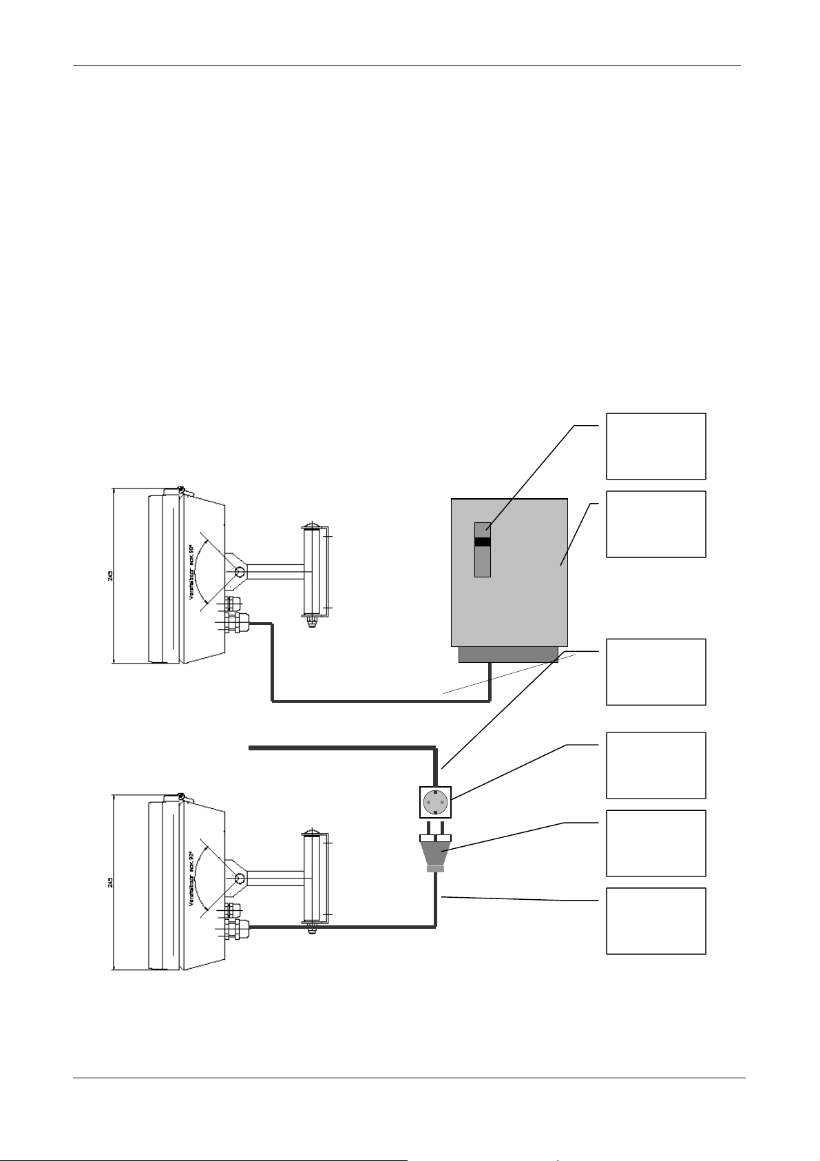
• Connecting the TRANSIT to the 120 Vac mains shall be in accordance with one of the two options shown
in the figures below.
• The safety switch shall be a two-pole switch, disconnecting the line and neutral, with a contact distance of at
least 3-mm.
Safety switch
120 Vac
Installation
connection
box
Fixed wiring
120 Vac
120 Vac wall
socket
120 Vac plug
Maximum
cable length
2 meters
© NEDAP IDEAS – AVI P.O. Box 103, NL-7140 AC GROENLO Page 6-41
Page 7
Version: 1.0, September 19, 2002 2 – INSTALLATION
t
T
2 INSTALLATION
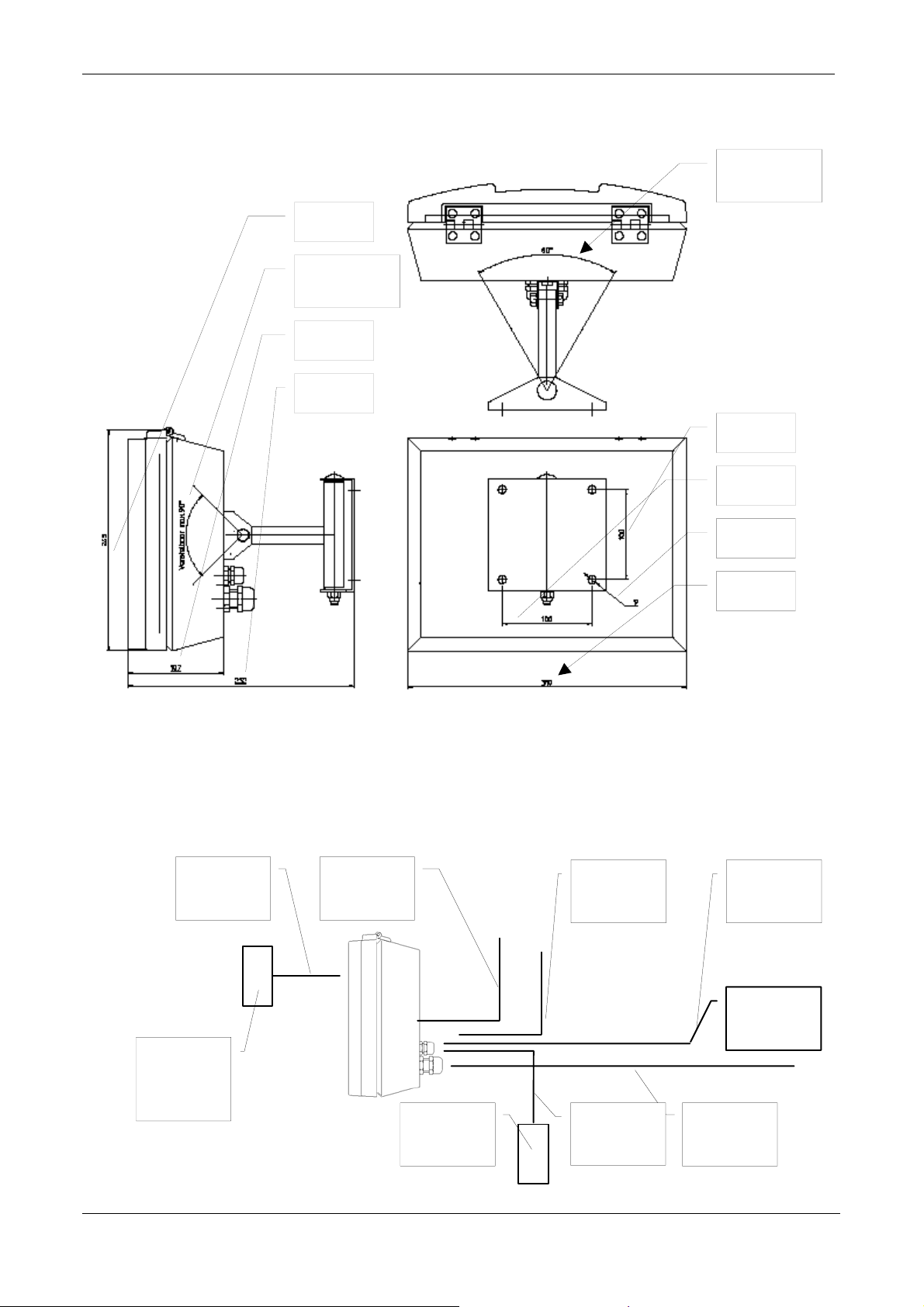
2.1 Installation.
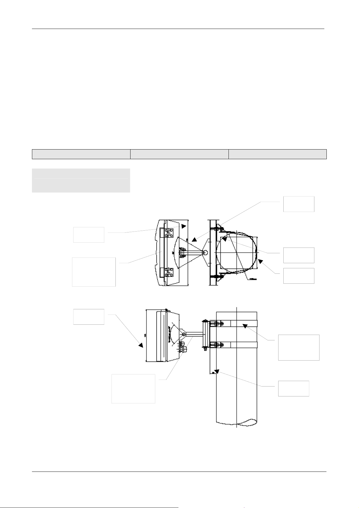
The TRANSIT reader can be installed in any position. Normally the reader shall be mounted in a horizontal
position, then the coverage area in the horizontal plane is maximized. In some applications a vertical installation
is required to make use of the smaller beam width in the vertical plane. The mounting brackets which make
rotation in the vertical and horizontal plane possible is standard included in every TRANSIT.
The following mast mounting part is available for the TRANSIT.
Part Description NEDAP article number
• Mast mounting set
2.1.1 Mast mounting.
310 mm
RANSIT
245 mm
Universal mast mounting set for
square and round masts. Max. 150
mm square and max. 190 mm round
Extension
bracket
5626595
+/- 30º
190 mm
max
150 mm
max
Mast
mounting
se
30 mm
© NEDAP IDEAS – AVI P.O. Box 103, NL-7140 AC GROENLO Page 7-41
Page 8
Version: 1.0, September 19, 2002 2 – INSTALLATION
2.1.2 Wall mounting.
Turn angle
+/- 30º
245 mm
Turn angle
+/- 45º
107 mm
252 mm
100 mm
100 mm
2.2 Basic connections.
120KHZ
MOD
RELAY
CONT
Reader
disable
9 mm
310 mm
HOST
COM
Host
system
Any
NEDAP
inductive
reader
© NEDAP IDEAS – AVI P.O. Box 103, NL-7140 AC GROENLO Page 8-41
External
antenna
Reflex-130
Reflex-130
INT
MAINS
Page 9
Version: 1.0, September 19, 2002 2 – INSTALLATION
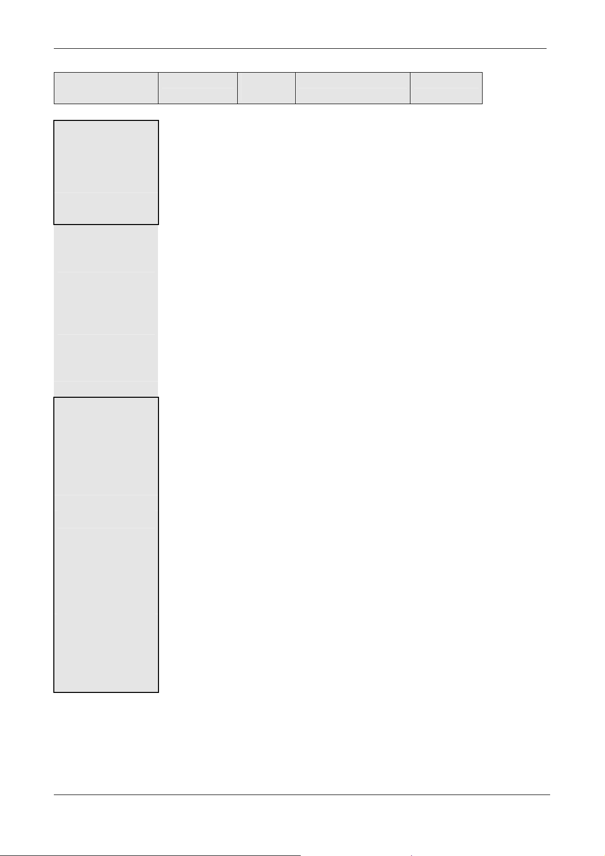
TRANSIT
Basic connections
Cable type Max
length
Functional description Signal names
MAINS
• MAINS-IN
3 * 0.75 mm2 N/A. System power supply.
The safety ground shall
be connected directly to
120VAC-L
120 VAC-N
Safety Ground
the chassis.
• DC-SUPPLY
2 * 1.5 mm2 N/A System power supply. +24VDC
GND
RELAY
CONT
3 * 0.75 mm2 25Vdc, 2 A
120Vac,
1A
Relay contacts normally
open, center contact and
normally closed.
COM
NC
NO
Reflex-130
INT
4 * 0.25 mm2
shielded
Maximum
15 meter
Connection to the
external inductive
antenna Reflex-130.
HF+
HF-
UL
GND
NA
HOST-COM
• B-W-O-OUT
4 * 0.25 mm2
shielded
Maximum
50 meter
Detected tag numbers
are packed according the
Bar-code-39, Wiegand26 or Omron-7811-2
protocol.
O-1
O-2
O-3
GND
Selected by EEPROM
• RS 232-C
3 * 0.25 mm2
shielded
cable capacity
Maximum
15 meter
When STANDARD
communication board is
placed.
TX
GND
RX
<= 100
pF/meter
• RS-422
4 * 0.25 mm2
shielded
cable capacity
<= 100
pF/meter
Maximum
1200 meter
When OPTIONAL
communication board is
placed.
TX-
TX+
RX-
RX+
GND
s
© NEDAP IDEAS – AVI P.O. Box 103, NL-7140 AC GROENLO Page 9-41
Page 10

Version: 1.0, September 19, 2002 2 – INSTALLATION
TRANSIT
Basic connections
Cable type Max
length
Functional description Signal names
Reader disable 2 * 0.25 mm2
shielded
Maximum
15 meter
Use always a relay
contact to connect the
internal 5 Vdc to the
Rdis
5V
Reader disable input.
Using an external
5 Vdc voltage can
damage the unit
120KHZ
MOD
Coax RG58U Maximum
100 meter
Connects any external
NEDAP inductive
reader to the TRANSIT.
The TRANSIT shall
modulate the received
tag data on the 120 kHz
signal from the inductive
reader. By doing this it
looks as if the
TRANSIT is an
inductive antenna for
the external inductive
reader.
HF+
HF-
© NEDAP IDEAS – AVI P.O. Box 103, NL-7140 AC GROENLO Page 10-41
Page 11

Version: 1.0, September 19, 2002 2 – INSTALLATION
2.3 Transceiver unit DIP-switch settings and indications and adjustments.
2.3.1 DIP switch settings.
FREQ
SEL
SW-1
DIP-switch
Transceiver unit
Switch
type
Function Description Switch
• SW-1
5 bit dip
switch
Frequency
selection.
LSB changes
results in 600 kHz
frequency
changes.
Channels select within sub band.
Channels select within sub band.
Channels select within sub band.
Channels select within sub band.
Sub band selection.
Frequency selection table.
SUBBAND 5
SW1 1 SW1 0
Frequency kHz S-1 S-2 S-3 S-4 Frequency kHz S-1 S-2 S-3 S-4
2.438.400 1 1 1 1 2.448.000 1 1 1 1
2.439.000 0 1 1 1 2.448.600 0 1 1 1
2.439.600 1 0 1 1 2.449.200 1 0 1 1
2.440.200 0 0 1 1 2.449.800 0 0 1 1
2.440.800 1 1 0 1 2.450.400 1 1 0 1
2.441.400 0 1 0 1 2.451.000 0 1 0 1
2.442.000 1 0 0 1 2.451.600 1 0 0 1
2.442.600 0 0 0 1 2.452.200 0 0 0 1
2.443.200 1 1 1 0 2.452.800 1 1 1 0
2.443.800 0 1 1 0 2.453.400 0 1 1 0
2.444.400 1 0 1 0 2.454.000 1 0 1 0
2.445.000 0 0 1 0 2.454.600 0 0 1 0
2.445.600 1 1 0 0 2.455.200 1 1 0 0
2.446.200 0 1 0 0 2.455.800 0 1 0 0
2.446.800 1 0 0 0 2.456.400 1 0 0 0
2.447.400 0 0 0 0 2.457.000 0 0 0 0
S-5 SUBBAND 6
S-5
number
S-1
S-2
S-3
S-4
S-5
© NEDAP IDEAS – AVI P.O. Box 103, NL-7140 AC GROENLO Page 11-41
Page 12
Version: 1.0, September 19, 2002 2 – INSTALLATION
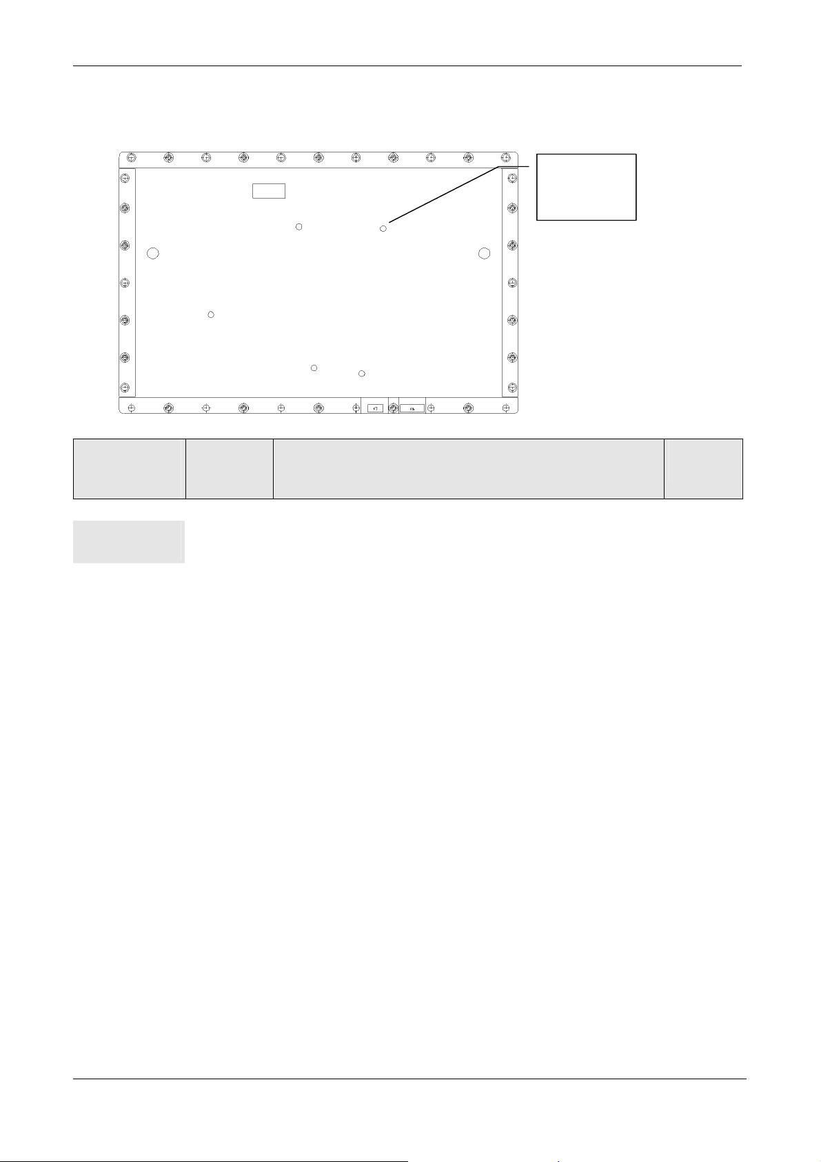
2.3.2 Transceiver unit indications.
PLL
LOCKED
D-7
Indications
Transceiver
unit
• PLL
LOCKED
Indication
type
Dual color
LED
Description Indication
Red indicates PLL is unlocked.
Green indicates PLL is locked.
number
D-7
© NEDAP IDEAS – AVI P.O. Box 103, NL-7140 AC GROENLO Page 12-41
Page 13
Version: 1.0, September 19, 2002 2 – INSTALLATION
T
R
A
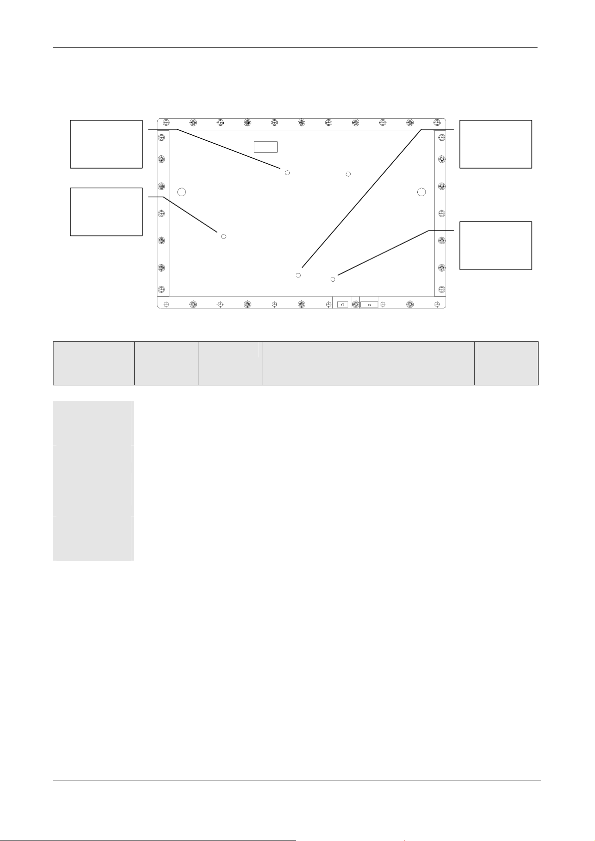
2.3.3 Transceiver unit adjustments.
FREQ
FINE
C-105
X-PW
ADJ
P-2
DD
ADJ
P-4
GC
LEVEL
P-3
Adjustments
Transceiver
Adjustment
type
Function Description Adjustment
number
unit
• FREQ -
FINE
Trim cap. Factory
setting
Fine tuning reference frequency for synthesizer. C-105
• TX-PWR
Trim pot. Customer
setting
Reduction transmitter power by maximum 20
dB. Maximum EIRP < 18 dBm .
P-2
• DD-ADJ
Trim pot. Factory
Received data duty cycle correction. P-4
setting
• AGC-
LEVEL
Trim pot. Factory
setting
AGC reference level adjustment. P-3
© NEDAP IDEAS – AVI P.O. Box 103, NL-7140 AC GROENLO Page 13-41
Page 14
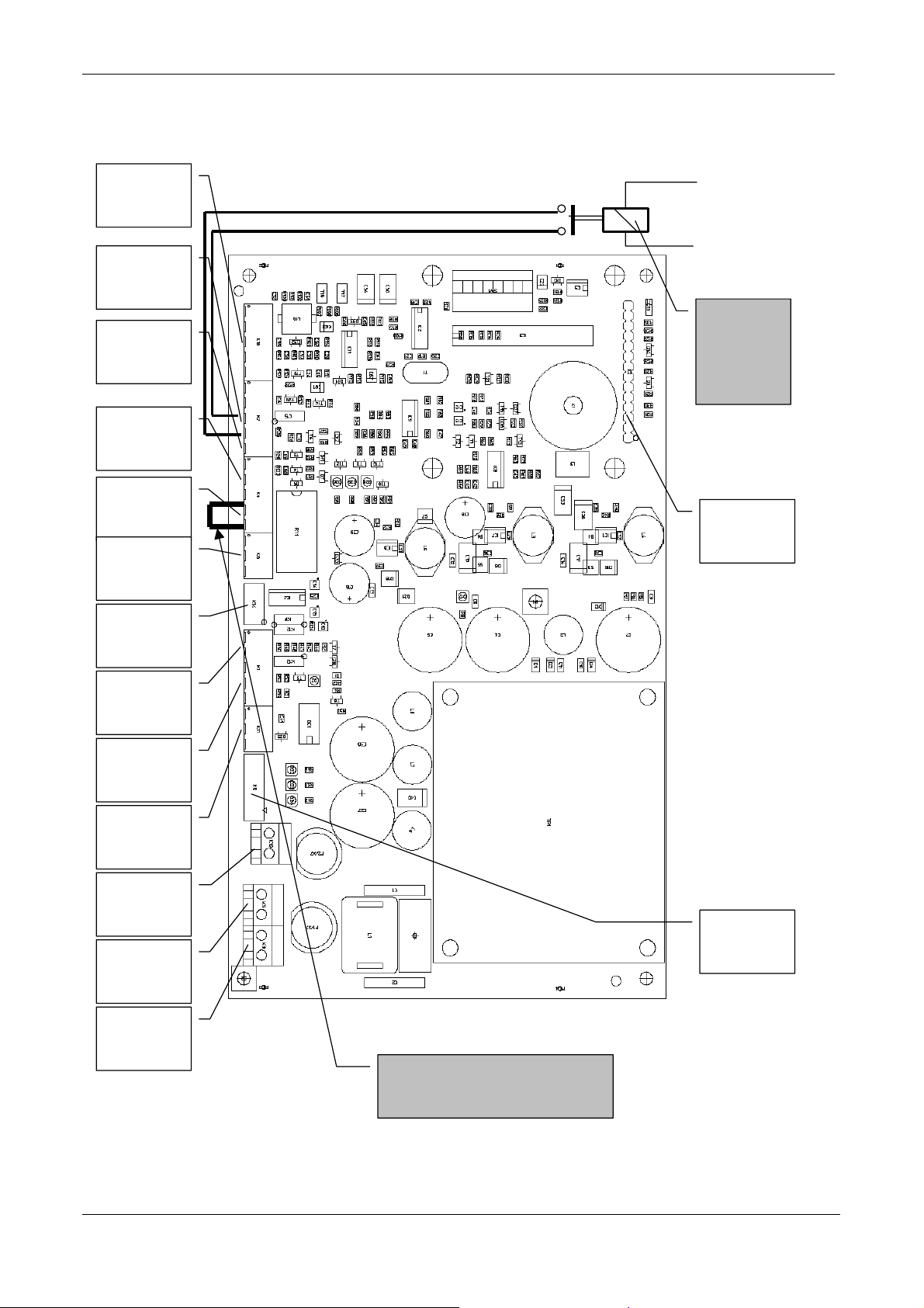
Version: 1.0, September 19, 2002 2 – INSTALLATION
TX
W
2.4 PS-270 connections, U-link & DIP-switch settings and indications.
Reflex-130
INT
K16
Reader disable
K7-3.K7-4
hen relay
B-W-O-OUT
GND
K7-5
B-W-O-OUT
K4-1..K-3
Door-contact
K4-4..K4-5
RELAY-
CONT
K6
is powered
the read
function is
disabled.
OPT COM
INT
K2
DATA-CNTL
K14
120 KHZ
MOD
K1-1..K1-2
-CONT
K1-3..K1-5
EXT-MOD-
UNIT
K11
DC-SUPPLY
K10
MAINS-OUT
K5
MAINS-IN
K3
DC-PWR
K8
PLACE THIS CONNECTION
WHEN DOOR CONTACT IS NOT
USED ! K4-4 -> K4-5
© NEDAP IDEAS – AVI P.O. Box 103, NL-7140 AC GROENLO Page 14-41
Page 15

Version: 1.0, September 19, 2002 2 – INSTALLATION
2.4.1 PS-270 connections.
PS-270
connections
• Reflex-130 INT
(K16)
• Reader disable
(K7-1..K7-4)
• B-W-O-OUT
(K7-5)
• B-W-O-OUT
(K4-1..K4-3)
• Door contact
(K4-4..K4-5)
• RELAY-CONT
(K6)
• DATA-CNTL
(K14)
• 120 KHZ-MOD
(K1-1..K1-2)
s
Connector
type
5-p mkds
phoenix
5-p mkds
phoenix
5-p mkds
phoenix
5-p mkds
phoenix
5-p mkds
phoenix
3-p mkds
phoenix
6 wire flat cable
PCB connector
Micro Match
2-p mkds
phoenix
Function Description Signal names Pin
number
External
connection
Reflex-130
Controls
the flow of
data to the
controller.
Code
emulation.
Code
emulation.
Door
contact
Floating
relay
contacts
Internal
connection
to
transceiver
unit
120 kHz
input from
120 kHz antenna con.
120 kHz antenna con.
LED cont. high pos. ID
Ground
LED cont. high neg. ID
Spare
Spare
Reader disable
+5 Vdc connection
Output for Omron,
Wiegand and Barcode.
Output for Omron,
Wiegand and Barcode
Ground
Door contact
Ground
Center contact
Normally closed contact
Normally open contact
Ground connection
Spare
TTL received tag data
Received signal strength
TTL signal PLL locked
TTL signal enable TX
120 kHz connection
120 kHz ground con.
HF+
HF-
UL
GND
NA
R-dis
5V
GND 5
O-1
O-2
O-3
Door
GND
COM
NC
NO
GND
Det-data-out
U-AGC
Locked
TX-enable
HF+
HF-
external
NEDAP
inductive
reader
1
2
3
4
5
1
2
3
4
1
2
3
4
5
1
2
3
1
2
3
4
5
6
1
2
© NEDAP IDEAS – AVI P.O. Box 103, NL-7140 AC GROENLO Page 15-41
Page 16

Version: 1.0, September 19, 2002 2 – INSTALLATION
PS-270
connections
Connector
type
Function Description Signal names Pin
number
• TX-CONT
(K1-3..K1-5)
2-p mkds
phoenix
Transmitter control
Ground for control sign.
TTL signal PPL locked
TTL input to enable TX
GND
LCK
TXD
3
4
5
• EXT-MOD-
UNIT
(K11)
3-p mkds
phoenix
Connects
received
tag data to
external
reader
Isolated ground.
Optical isolated current
loop connection.
5 Vdc supply optocoupler.
GND
CLS
+5V
1
2
3
• DC-SUPPLY
(K10)
2-p mkds
phoenix
External
DC power
connection
External 24 Vdc input
External DC supply
ground.
+24Vdc
GND
1
2
• MAINS-OUT
(K5)
2-p mkds
phoenix
Internal
connection
to NX-500
optional
120 Vac output line.
120 Vac output neutral
120Vac
120Vac
1
2
board.
• MAINS-IN
(K3)
2-p mkds
phoenix
External
AC power
120 Vac input line
120 Vac output neutral
120Vac
120Vac
1
2
connection
• DC-PWR
(K8)
10 wire flat
cable PCB
connector
Micro Match.
Internal
connection
to
transceiver
unit.
Ground connection.
+15 Vdc connection
+15 Vdc connection
Ground connection.
-15 Vdc connection
-15 Vdc connection
Ground connection.
+ 5 Vdc connection
+ 5 Vdc connection
Ground connection.
1
2
3
4
5
6
7
8
9
10
rr
© NEDAP IDEAS – AVI P.O. Box 103, NL-7140 AC GROENLO Page 16-41
Page 17

Version: 1.0, September 19, 2002 2 – INSTALLATION
PS-270
connections
Connector
type
Function Description Signal names Pin
number
• OPT COM INT
(K2)
14 pen male
connector 15.8
mm
Connection to
optional
communication
board.
Not connected.
TTL TX-data com.
TTL RX-data com.
Ready to send
Cleared to send.
Ground
Ground
5 Vdc output
RS 485 I/O toggle
signal.
Not connected.
Ground
24 Vdc output for com.
board.
Not connected.
Not connected
TX
RX
RTS
CTS
GND
GND
XV5P
I/O
GND
XV24P
1
2
3
4
5
6
7
8
9
10
11
12
13
14
© NEDAP IDEAS – AVI P.O. Box 103, NL-7140 AC GROENLO Page 17-41
Page 18
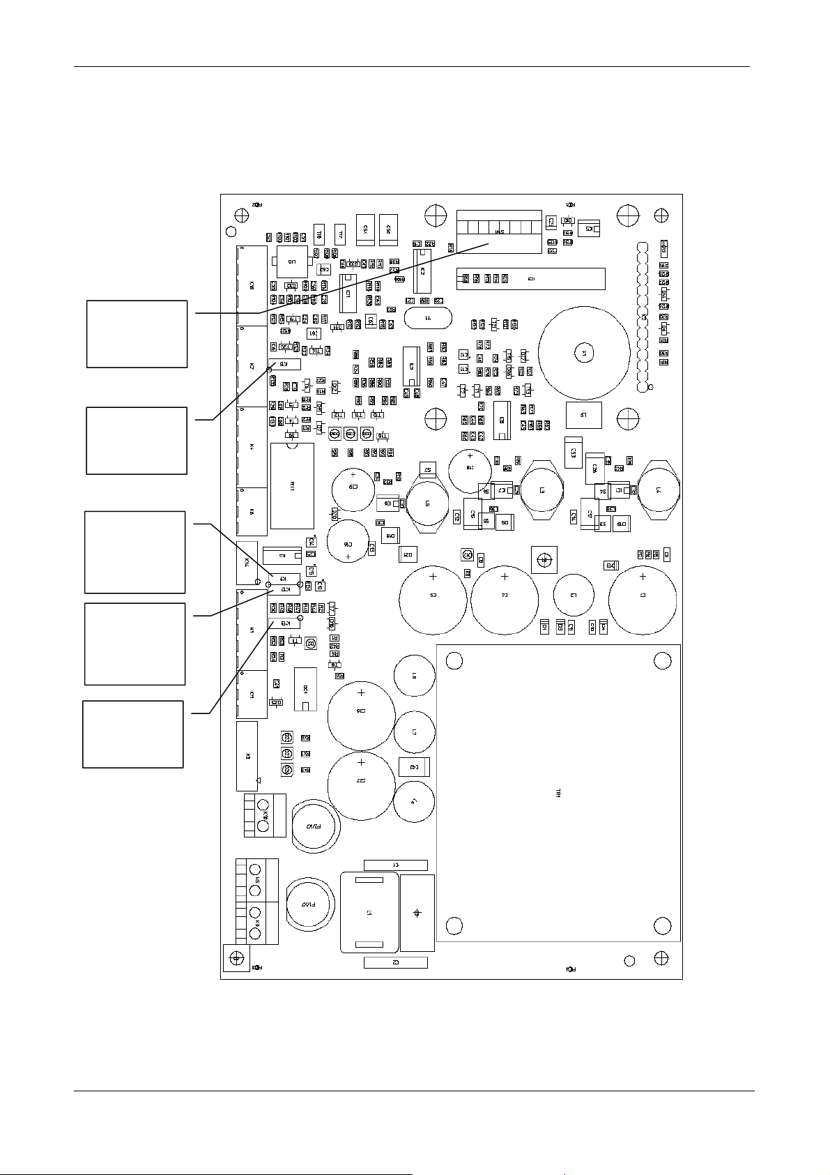
Version: 1.0, September 19, 2002 2 – INSTALLATION
2.4.2 PS-270 U-Link & DIP-switch settings.
2.4.2.1 U-links.
DIP SWITCH
SW-1
Range beep
on/off
K-15
DATA /
DATA*
controller
K-9
DATA /
DATA*
modulator
K-12
Inductive
Mod select
K-13
© NEDAP IDEAS – AVI P.O. Box 103, NL-7140 AC GROENLO Page 18-41
Page 19

Version: 1.0, September 19, 2002 2 – INSTALLATION
PS-270
U-link
U-link
position
Description U-link
number
settings
• Invert
microwave data
1 Inverts uWave TTL data (default position)
2 Inverts uWave TTL data.
K-9
• Range beep
function
1 Selects range beep function off. (default
position)
K-15
2 Selects range beep function on.
• Inverts
inductive
modulator data
1 Inverts TTL data from uW-receiver and
inductive-receiver to modulator. (default)
2 Inverts TTL data from uW-receiver and
K-12
inductive-receiver to modulator.
• Inductive
Mod select
1 Selects modulator setting for voltage
coupled receivers.
K-13
2 Selects modulator setting for current
coupled receivers. (As is needed for the
NX500 or SimpleXS) (default)
2.4.2.2 DIP-switch SW-1 settings.
Refer for the DIP-switch settings to the manual of the loaded firmware.
© NEDAP IDEAS – AVI P.O. Box 103, NL-7140 AC GROENLO Page 19-41
Page 20
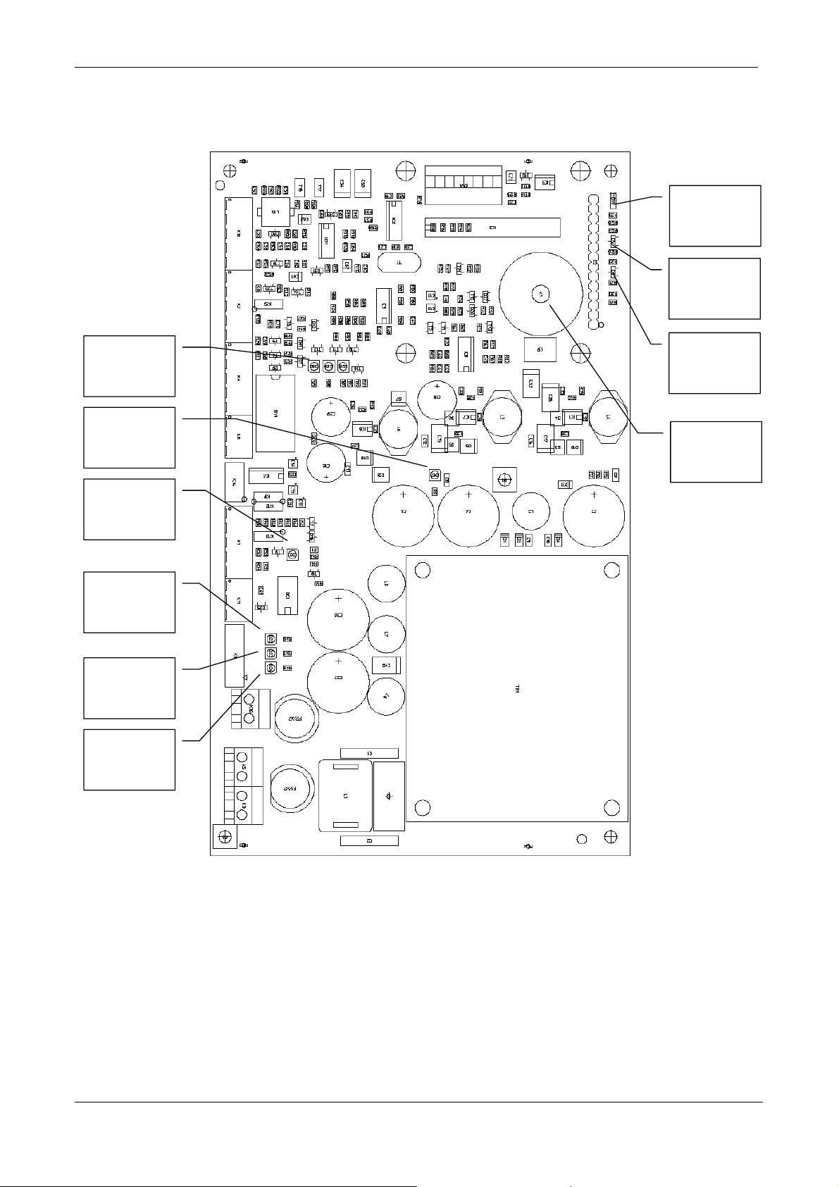
Version: 1.0, September 19, 2002 2 – INSTALLATION
R
2.4.3 PS-270 indications.
DOO
CLOSED
D-15
STS
ID
D-14
RX-
LEVEL
D-28..D-30
DCRAW
D-17
PLL
LOCKED
D-2
+5 Vdc
PRESENT
D-22
-15 Vdc
PRESENT
D-23
+15 Vdc
PRESENT
D-24
NA
UL
D-6
RANGE
BUZZER
X-1
© NEDAP IDEAS – AVI P.O. Box 103, NL-7140 AC GROENLO Page 20-41
Page 21

Version: 1.0, September 19, 2002 2 – INSTALLATION
PS-270
Indications
Indication
type
Description Indication
number
• RX-LEVEL
LED red LED bar indicating the received tag signal strength. D-28..D-
30
• DC-RAW
LED green LED active indicates that the DC supply is present. D-17
• PLL
LED green LED active indicates PLL is locked. D-2
LOCKED
• +5 Vdc
LED green LED active indicates that this voltage is present. D-22
PRESENT
• -15 Vdc
LED green LED active indicates that this voltage is present. D-23
PRESENT
• +15 Vdc
LED green LED active indicates that this voltage is present. D-24
PRESENT
• NA
• UL
Dual color
LED= red
Dual color
LED= green
LED indicates that the TRANSIT is standby and the door is
locked
LED indicates that a tag is detected, shall stay active during
unlock time. The door is unlocked.
D-6
D-6
• STS
• ID
Dual color
LED= red
Dual color
LED indicates that processor is running by showing heartbeat
D-14
(blinking).
LED active during tag recognition (fast blinking). D-14
LED= green
• DOOR
LED red LED active indicates door contact closed. D-15
CLOSED
• RANGE
BUZZER
Sound When activated by U-link K-15 and a valid tag is present the
beep repeat frequency gives an indication for the received signal
X-1
strength from the tag.
© NEDAP IDEAS – AVI P.O. Box 103, NL-7140 AC GROENLO Page 21-41
Page 22
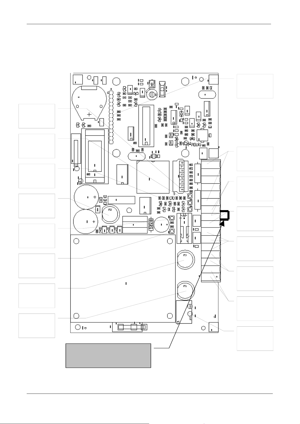
Version: 1.0, September 19, 2002 2 – INSTALLATION
A
2.5 Optional NX-500 board, TRANSIT Extended only.
D5
RELAY
CTIVATED
D4
DOOR
CONTACT
D3
PORTER
CONTACT
24 Vdc
FUSE
1A SB
D2
DETECTION
STATUS
D1
PROG.
STATUS
24 Vdc
FUSE
1A SB
MAINS
FUSE
0.3A SB
PLACE THIS CONNECTION
WHEN DOOR CONTACT IS
NOT USED! K2-9->K2-10
OPT COM
Reflex-130
K2-11..K2-16
DOOR
CONTACT
K2-9 .. K2-10
MANUAL
RELEASE
K2-8 .. K2-9
RELAY
CONT
K2-5 .. K2-7
24 Vdc OUT
K2-3 .. K2-4
24 VDC IN
K2-1..K2-2
MAINS-IN
INT
K4
INT
K1
© NEDAP IDEAS – AVI P.O. Box 103, NL-7140 AC GROENLO Page 22-41
Page 23

Version: 1.0, September 19, 2002 2 – INSTALLATION
2.5.1 Connections.
NX-500
Connections
MAINS-IN
(K1)
24 VDC IN
(K2-1 .. K2-2)
24 VDC OUT
(K2-3 .. K2-4)
RELAY
CONT
(K2-5 .. K2-7)
MANUAL
RELEASE
(K2-8 .. K2-9)
DOOR
CONTACT
(K2-9 .. K2-10)
Reflex-130
INT
(K2-11 .. K2-16)
Cable type Max
Functional description Pin
length
3 * 0.75 mm2 N/A. System power-supply.
The safety ground shall
be connected directly to
the chassis.
2 * 0.75 mm2 N/A System emergency
power-supply.
2 * 0.4 mm2 Maximum
100 meter
3 * 0.75 mm2 25Vdc, 2 A
120Vac,
1A
2 * 0.25 mm2 Maximum
100 meter
DC supply intended for
lock control
Relay contacts normally
open, center contact and
normally closed.
Connect to push button
to indicate manual door
release.
2 * 0.25 mm2 Maximum
100 meter
5 * 0.25 mm2
shielded
Maximum
50 meter
Connect to door contact
To indicate door closed
Connection to the
external inductive
antenna Reflex-130.
number
1
2
1
2
3
4
5
6
7
8
9
9
10
11
12
13
14
15
16
Signal names
120VAC-L
120 VAC-N
Safety Ground
+24VDC
GND
+24VDC
GND
NC
COM
NO
PORT
GND
GND
DOOR
HF+
GND
UL
GND
NA
IND
© NEDAP IDEAS – AVI P.O. Box 103, NL-7140 AC GROENLO Page 23-41
Page 24

Version: 1.0, September 19, 2002 2 – INSTALLATION
NX-500
Connections
Cable type Max
length
Functional description Pin
number
Signal names
OPT COM INT
(K2)
14 pin male
connector 15.8
mm.
Connection to
optional
communication
board.
Not connected.
TTL TX-data com.
TTL RX-data com.
Ready to send
Cleared to send.
Ground
Ground
5 Vdc output
RS 485 I/O toggle
signal.
Not connected.
Ground
24 Vdc output for com.
board.
Not connected.
Not connected
1
2
3
4
5
6
7
8
9
10
11
12
13
14
TX
RX
RTS
CTS
GND
GND
XV5P
I/O
GND
XV24P
2.5.2 Indications.
NX-500
Indications
PROG.
STATUS
DETECTION
STATUS
PORTER
CONTACT
DOOR
CONTACT
RELAY
ACTIVATED
Indication
type
LED red 1 sec on / 1 sec off : Program is operational
Description Indication
number
D-1
1 short flash: Not enough RAM.
2 short flashes: RAM failure.
3 short flashes: EPROM failure
LED green FLASH: Transponder/XS-card detected; authorized and not
D-2
authorized.
LED green Activated when manual door-release button activated. D-3
LED green Activated when door contact is closed. D-4
LED green Activated when relay is activated. D-5
© NEDAP IDEAS – AVI P.O. Box 103, NL-7140 AC GROENLO Page 24-41
Page 25

Version: 1.0, September 19, 2002 3 – Communication interfaces.
3 Communication interfaces.
3.1 Connections to inductive readers.
The TRANSIT features two ways to connect it to external inductive NEDAP readers.
• Bringing the 120 kHz antenna signal of the external inductive reader to the TRANSIT and connecting it to
120 kHz-MOD connector of the Power supply unit (K1-1 and K1-2). The TRANSIT will modulate the
received tag data on the 120 kHz antenna signal of the external inductive reader. The TRANSIT looks for
the external inductive reader as an antenna. This feature makes the application of the TRANSIT simple in
existing installations. To optimize the quality of the modulating signal the modulation depth can be selected
in accordance with the type of receiver used in the external inductive reader. The U-Link setting: “ Inductive
Mod select, K-13”, on the Power supply unit allows for the selection between voltage- or current coupled
receivers. Contact NEDAP when in doubt which kind of external inductive receiver you want to connect to
the TRANSIT system.
• Remember that when using the modulation function of the TRANSIT on the 120 kHz antenna signal of an
external inductive reader, to select external antenna (tuning) on this inductive reader. For the Accessor III-A
and Accessor III-B for example this shall be realized by setting J1 in the external position.
3.2 Connections via the special code emulation outputs.
• The outputs OUT-1, OUT-2 and OUT-3 used for the emulated output for Wiegand 26, Omron, Barcode
and others are vulnerable for large potential differences. Care shall be taken to connect always the ground of
the receiving system to the TransIT and use shielded cable.
3.3 Removing the optional communication boards.
• Remove the optional communication boards only when the TransIT is disconnected from the mains supply,
not doing this will damage the communication board.
© NEDAP IDEAS – AVI P.O. Box 103, NL-7140 AC GROENLO Page 25-41
Page 26
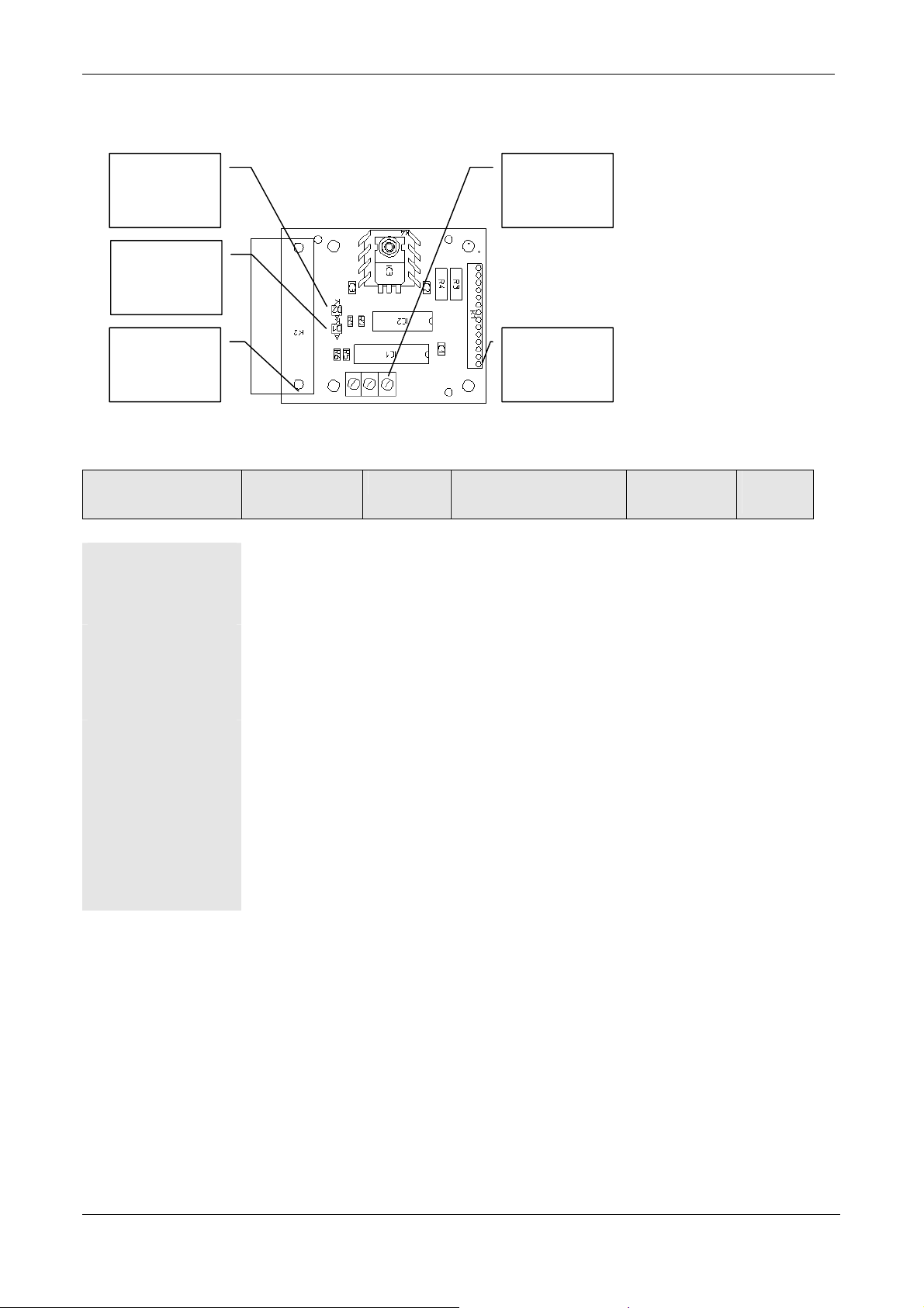
Version: 1.0, September 19, 2002 3 – Communication interfaces.
T
3.4 RS 232 (RS 232 III, Art. No.: 7806434)
RX-LED
X-LED
D25 CON
K-2
Internal interface
RS 232 III
Connector
type
Function Description Signal names Pin
• OPT COM INT
(K2)
14 pen male
connector 15.8
mm
Connection to
Powersupply unit.
See par 3.1.3.2
• RS232 3 pin
CON K-3
3 pin WECO
PCB
RS 232
connection
Transmit (output)
Ground
Receive (input)
• D25 CON K-2
D25 connector
female
RS 232
connection
Transmit (output)
Receive (input)
Do not connect.
Do not connect
Ground (shield)
Identifier (max 100 mA)
Do not connect
RS232 3 pin
CON
K-3
OPT-COM
INT
K-1
number
See par 3.1.3.2 See par
3.1.3.2
Tx
GND
Rx
Tx
Rx
RTS
CTS
GND
+5Vdc
DTR
1
2
3
2
3
4
5
7
9
20
© NEDAP IDEAS – AVI P.O. Box 103, NL-7140 AC GROENLO Page 26-41
Page 27
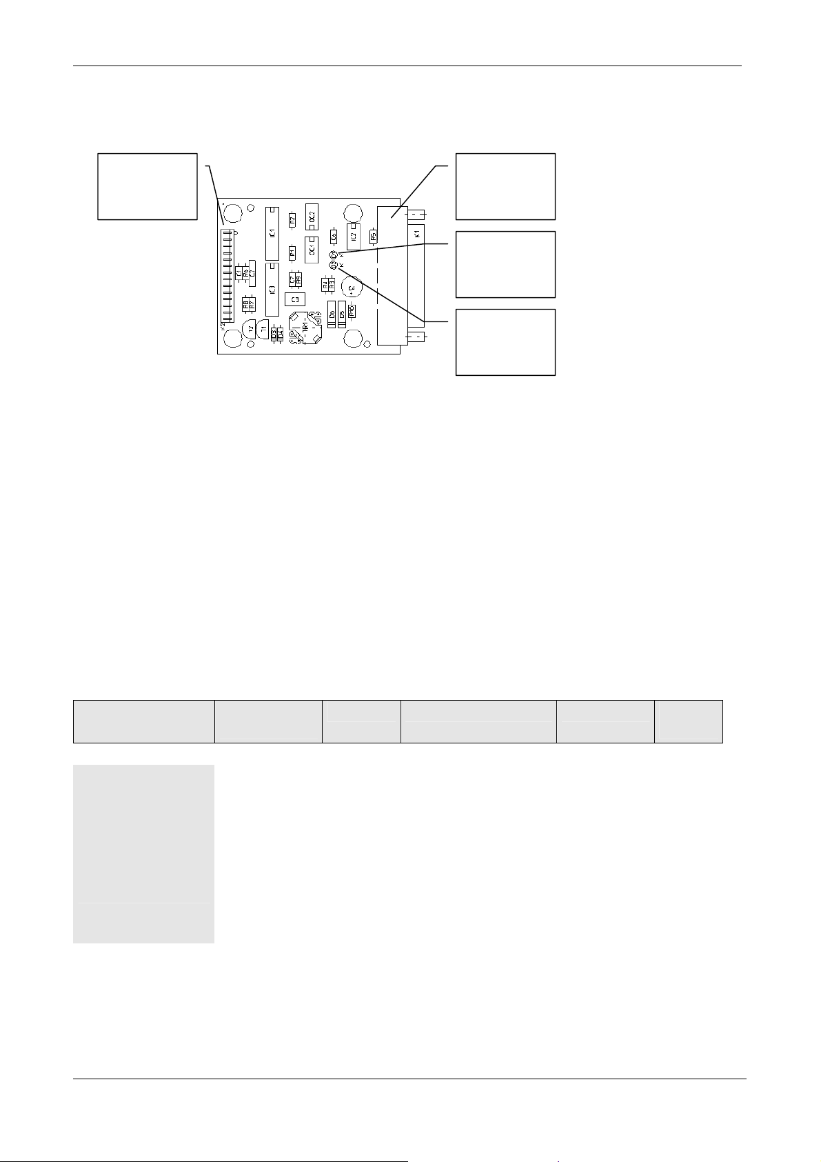
Version: 1.0, September 19, 2002 3 – Communication interfaces.
T
3.5 RS 422 (CM-422, Art. No.: 7811730)
OPT-COM
INT
K-2
D25 CON
K-1
X
LED
RX
LED
• The CM 422 board has galvanic isolation.
• Maximum data rate 9600 baud.
• The LED’s are indicating respectively that data is being transmitted (Tx) and data being received (Rx).
• The RX- and RX+ lines are always terminated with a 120 Ω resistor.
• The TX- and TX+ lines have to be terminated at the host side.
• Connection to host:
• RX+ => TX- (host)
• RX- => TX+ (host)
• TX+ => RX- (host)
• TX- => RX+ (host)
Internal interface
CM 422
Connector
type
Function Description Signal names Pin
number
• OPT COM INT
K-2
14 pen male
connector 15.8
mm
Connection to
Power
supply unit.
See par 3.1.3.2
See par 3.1.3.2 See par
3.1.3.2
• D 25 CON K-1
D25 connector
female
RS 422
connection
Receive* (input)
Receive (input)
Transmit* (output)
Transmit (output)
RX-
RX+
TX-
TX+
15
17
19
25
© NEDAP IDEAS – AVI P.O. Box 103, NL-7140 AC GROENLO Page 27-41
Page 28
Version: 1.0, September 19, 2002 3 – Communication interfaces.
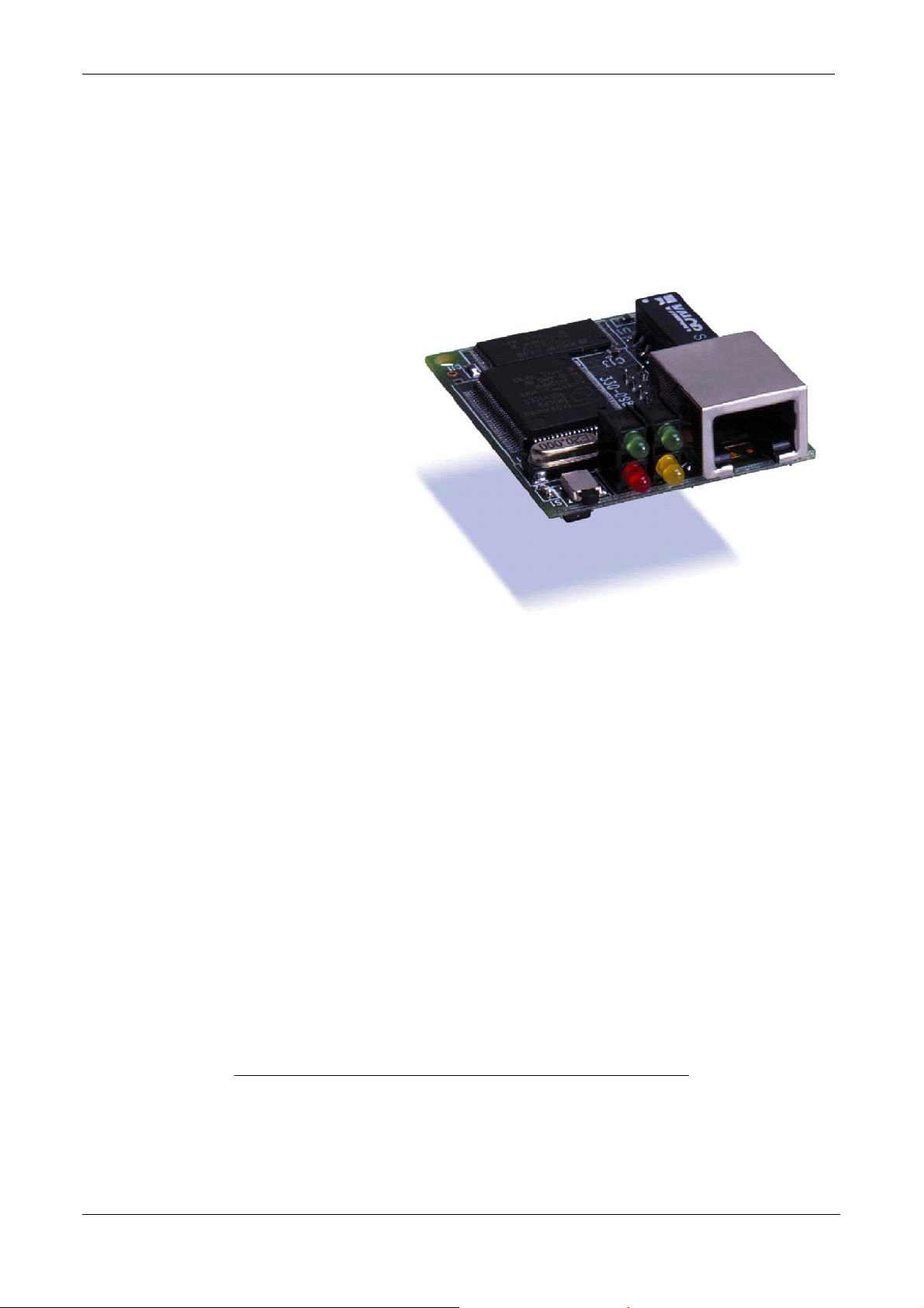
3.6 Universal thin server. ( Art. No.: 7806434 )
The Universal Thin Server (UTS) is designed to connect NEDAP RF-ID devices with a serial interface to an
Ethernet network using the TCP/IP protocol.
The Ethernet network interface speed is 10-Mbit.
3.6.1 LED Status Display
3.6.1.1 Yellow and Green LED
The green LED displays the status of the
serial channel (the red LED will be off
while in normal operation).
Stable color : Channel idle, no
connection
Blinking, 1 sec cycle : Connected over
the network
3.6.1.2 Red LED
If the red LED is on or blinking, the green LED will give a diagnostics code. There is a fatal error, and the UTS
is not working.
Red LED stable on, green LED blinking:
1x: EPROM-checksum error
2x: RAM-error
3x: Network controller error (Token Ring)
4x: E²PROM checksum error or bad
5x: IP address already used on network
Red LED blinking, green LED blinking:
4x: The network connection is faulty. This code should only appear after power up. Even though the
UTS is going into operation mode, the problem will potentially persist.
5x: No DHCP response was received.
See user manual Universal Thin Server for detailed information
© NEDAP IDEAS – AVI P.O. Box 103, NL-7140 AC GROENLO Page 28-41
Page 29
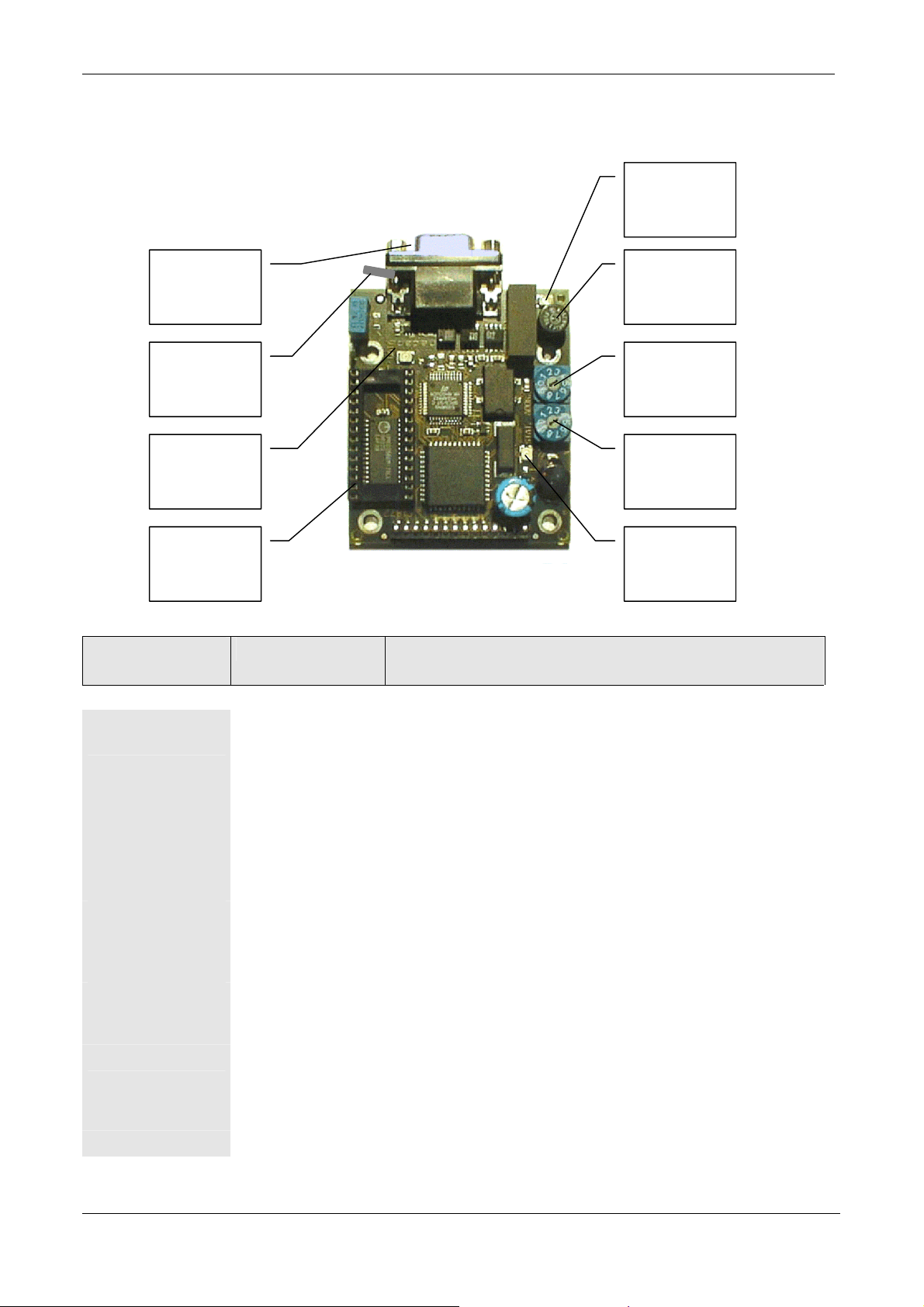
Version: 1.0, September 19, 2002 3 – Communication interfaces.
3.7 Profibus DP (Art. No: 7817134)
Power Led
(Red)
Profibus
Socket
Fuse
T315 mA
Grounding
Tab
Station
address
(X1)
Profibus Led
(Red)
Station
address
(X10)
EPROM
Socket
Status Led
(Green)
Profibus
Function Description
Indications
• Profibus
socket
• Station
address X1 and
X10
Connection for
Profibus Cable
Address setting With these two rotation switches a station address from 0 –99
Here the Profibus Cable must be connected
can be selected. Use switch X1 to select the units an x10 to
select the tens. Addresses lower then 3 are mostly used by the
Profibus master so it is recommended not to use the values 0 –
2.
• Power LED
Indication Red This LED indicates that power is available. This LED should
always be on as soon as power is turned on.
• Status LED
Indication Green This LED indicates the status of the Profibus DP Interface
Module and should always blink. The status is indicated by the
on and off time of the LED. See manual for all possible status
indications.
• Profibus LED
Indication Red This LED will be on when the Profibus master recognizes the
interface module. When this LED is off then this mostly
indicates an error at the Profibus master
• Grounding tab
Earth connection I connected to Profibus cable shield and must be connected to
ground.
• Fuse
Overload protection Protects the galvanic isolated Profibus circuit. Fuse is blown
when Power LED is off and status LED is still blinking.
• Eprom socket
Here the Eprom with the embedded software will be inserted.
© NEDAP IDEAS – AVI P.O. Box 103, NL-7140 AC GROENLO Page 29-41
Page 30

Version: 1.0, September 19, 2002 4 – APPLICATION INFORMATION
4 APPLICATION INFORMATION
4.1 Available embedded software.
The TRANSIT communication features are defined by the firmware loaded in to the micro controller located on
the Power supply unit PS-270. The micro controller is a Micro Chip PIC 16F876-20I / SP
(NEDAP Art. No.: 2802260).
For every firmware version an installation guide is available. The firmware can be loaded and upgraded in the
PIC using a special software tool.
Contact Nedap for the possibilities.
4.2 Coverage area.
Transponder
Maximum
range 10 m
Line of sight
45 °
5 m
The TRANSIT system operates in the 2.4 to 2.45 GHz ISM band. The labels used with the TRANSIT system
are all equipped with lithium battery’s to power the internal logic. The labels do not contain a transmitter but are
using the received power from the reader, after modification, for re-transmission to the reader. This principle is
called modulated backscatter The labels are so called field modifying devices. The received RF power from the
reader is modulated with the data from the chip containing the ID-number. To read a label there has to be a line
of side to the label from the reader. Most synthetic materials are transparent for RF energy with little attenuation
and are forming no obstruction. Snow and ice are no problem as long as it is in crystal form. Closed water films
are a problem for the detection range. Heavy rain shall be no problem as long as there is no closed water film on
the TRANSIT front cover or on the label. To reduce the influence of unwanted reflections circular polarization
is used, this brings also rotation freedom for the label. Placing the labels on metal surface is not influencing the
read range. One has to keep in mind that the misalignment is most of the time present in two planes. This makes
simple evaluation of the coverage area difficult. A computer model has been developed in which most
geometry’s can be evaluated. Contact Nedap when in doubt.
The antenna diagram of the TRANSIT has a vertical beam width of 40° and a horizontal beam width of 80°.
The labels are having a symmetrical diagram, 80° in the horizontal and vertical plane. The coverage area is based
on the combination of the two diagrams. When defining the reading range between reader and label one should
take in account the misalignment between reader and label. Good practice is to reduce the read range by a factor
of two when the label is on the –3 dB points of the reader antenna and the normal on the label still parallel to the
main axes of the reader.
One has to keep in mind that the misalignment is most of the time present in two planes. This makes simple
evaluation of the coverage area difficult. A computer model has been developed in which most geometries can
be evaluated. Contact Nedap when in doubt. In par. 4.5 the detection area for a number of practical situations is
given.
© NEDAP IDEAS – AVI P.O. Box 103, NL-7140 AC GROENLO Page 30-41
Page 31

Version: 1.0, September 19, 2002 4 – APPLICATION INFORMATION
4.3 Speed limitations.
The maximum speed a transponder can pass the reader antenna and the transponder can be read is depended on
the following factors:
Item Typical value
• Length of the detection trajectory.
• Distance between reader and tag.
• Number of valid frames needed for valid read.
• Length of code.
• Data rate
• Frame time
In this situation a maximum speed of 200 km/hour can be allowed. For every other geometry one should
carefully consider the above mentioned parameters before a specification on the maximum speed is defined.
This speed can ONLY be obtained with firmware in the 54 bit detection mode, see firmware user manuals.
6 meter
5 meter
3
64 bits
1.875 KBPS
34 msec
4.4 Using more systems at the same location.
When two or more systems are within a range of 15 meters, these systems should have a frequency offset of at
least 600 kHz with respect to each other. The frequency should be factory set. When in doubt or when two
readers are ‘looking’ to each other, frequency offset is recommended. This frequency offset has to stay within the
local radio regulations.
When two readers are heaving a frequency offset they can be mounted close together and they can read the same
label at the same time.
© NEDAP IDEAS – AVI P.O. Box 103, NL-7140 AC GROENLO Page 31-41
Page 32

Version: 1.0, September 19, 2002 4 – APPLICATION INFORMATION
4.5 Read range control TRANSIT-SUB. (Art. 7800150)
Until now to only possible way to reduce the reading distance of the TRANSIT in a controlled way was the use
of so called reference transponders. A transponder without the correct customer code was placed in the reading
area in such a way that only transponders which had a return signal stronger then this reference transponder
could be recognized by the TRANSIT.
Due to the fact that it is not always possible to find a good position for a reference transponder or due to the
fact that it is not possible to use a reference transponder from a cost or esthetical stand point the TRANSIT
SUB ( Squelch Upgrade Board) was developed.
TRANSIT SUB is a small PCB board which can be build into any TRANSIT.
TRANSIT SUB makes use of the already available AGC voltage (Automatic Gain Control Voltage) present in
the Transceiver unit. This AGC- voltage represents the received signal strength of a transponder in front of the
TRANSIT. When the orientation is fixed and no changes are present in the propagation path when the
transponder is approaching the TRANSIT, this AGC voltage is a good measure for the distance between
TRANSIT and transponder.
For the TRANSIT’s equipped with the PS-270 Power-supply and the firmware P-61, Q-70 and P-70 there is the
possibility to set the squelch reference level by means of commands via the serial data communication channel
when the DC2/DC4 asynchronous protocol is selected.
4.5.1 Content TRANSIT retrofit kit.
• 1x Printed circuit board TRANSIT SUB. (article 7800150)
• 3x Adhesive printed circuit board mounting supports.
• 1x 10 wire flat wire cable of approximately 100 mm.
• 1x 6 wire flat wire cable of approximately 100 mm.
• 3 colored wires for connecting the TRANSIT SUB to the PS-270 power supply unit.
WARNING:
When the TRANSIT SUB is placed and minimum squelch level is selected the maximum read range
can be shorter then without the TRANSIT SUB.
© NEDAP IDEAS – AVI P.O. Box 103, NL-7140 AC GROENLO Page 32-41
Page 33
Version: 1.0, September 19, 2002 4 – APPLICATION INFORMATION
4.5.2 Theory of operation.
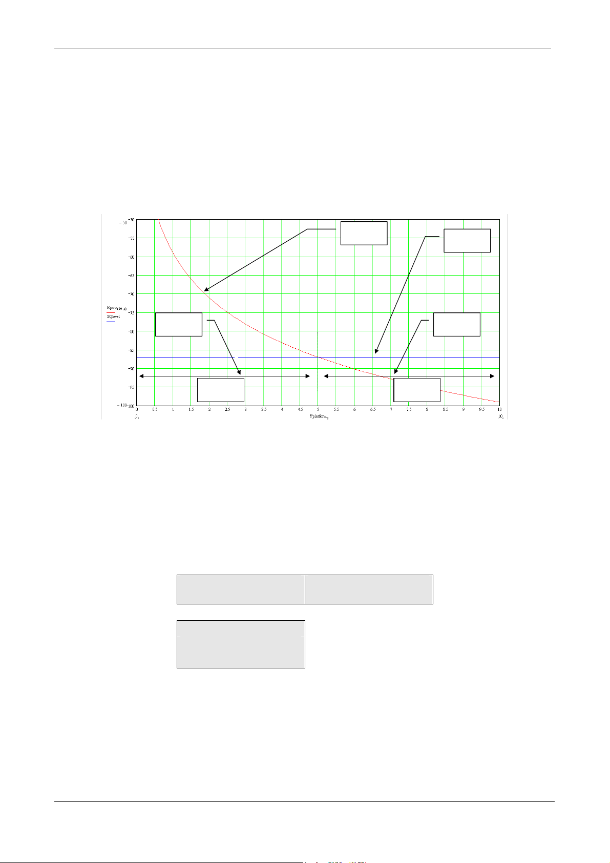
When a transponder is moving towards the TRANSIT the received signal strength will change as function of
distance. It should be clear that also tag orientation with respect to the TRANSIT reader determines the received
signal strength. The AGC voltage (U-agc, agc = automatic gain control) is proportional to the received signal
strength. TRANSIT SUB compares this voltage to an user settable reference voltage. This reference voltage is
called the squelch level (SQ-level). When U-agc < SQ-level the squelch is active (SQ-ON) and the received
transponder signals are suppressed. When Uagc > SQ-level the squelch is not active (SQ-OFF) and the received
transponder signals are normally processed.
U-agc
U-agc >
SQ-level
SQ-OFF SQ-ON
SQ-level
U-agc <
SQ-level
4.5.3 Squelch level setting.
The TRANSIT SUB has two ways of setting the squelch level (SQ-level); locally or remotely . Locally the squelch
level can be set by means of potentiometer P-2 when the U-links K-7 and K-6 are set for position 2. Remotely
the squelch level can be set by means of software commands, when the U-links K-7 and K-6 are set for position
1, which are controlling a so called DCP (digitally controlled potentiometer). The DCP has 100 positions and
controls in this way a dynamic range of approximately 70 dB which means per step 0.7 dB in transponder return
signal. Due to the fact that there is no linear relation between the transponder return signal and the distance the
following relation between DCP step and distance is valid.
Transponder Distance
meter
Change in distance for 1
step DCP in cm
2 10
4 15
8 25
The DCP rate of change when commanded up or down can be selected between fast and slow. Default is slow.
To step through the complete dynamic range (100 steps) between 100 and 50 seconds is needed in SLOW mode.
To step through the complete dynamic range (100 steps) between 20 and 17 seconds is needed in FAST mode.
For more detailed information refer to Manual TransIT-SUB
© NEDAP IDEAS – AVI P.O. Box 103, NL-7140 AC GROENLO Page 33-41
Page 34
Version: 1.0, September 19, 2002 4 – APPLICATION INFORMATION
4.6 Typical situations.
4.6.1 Introduction.
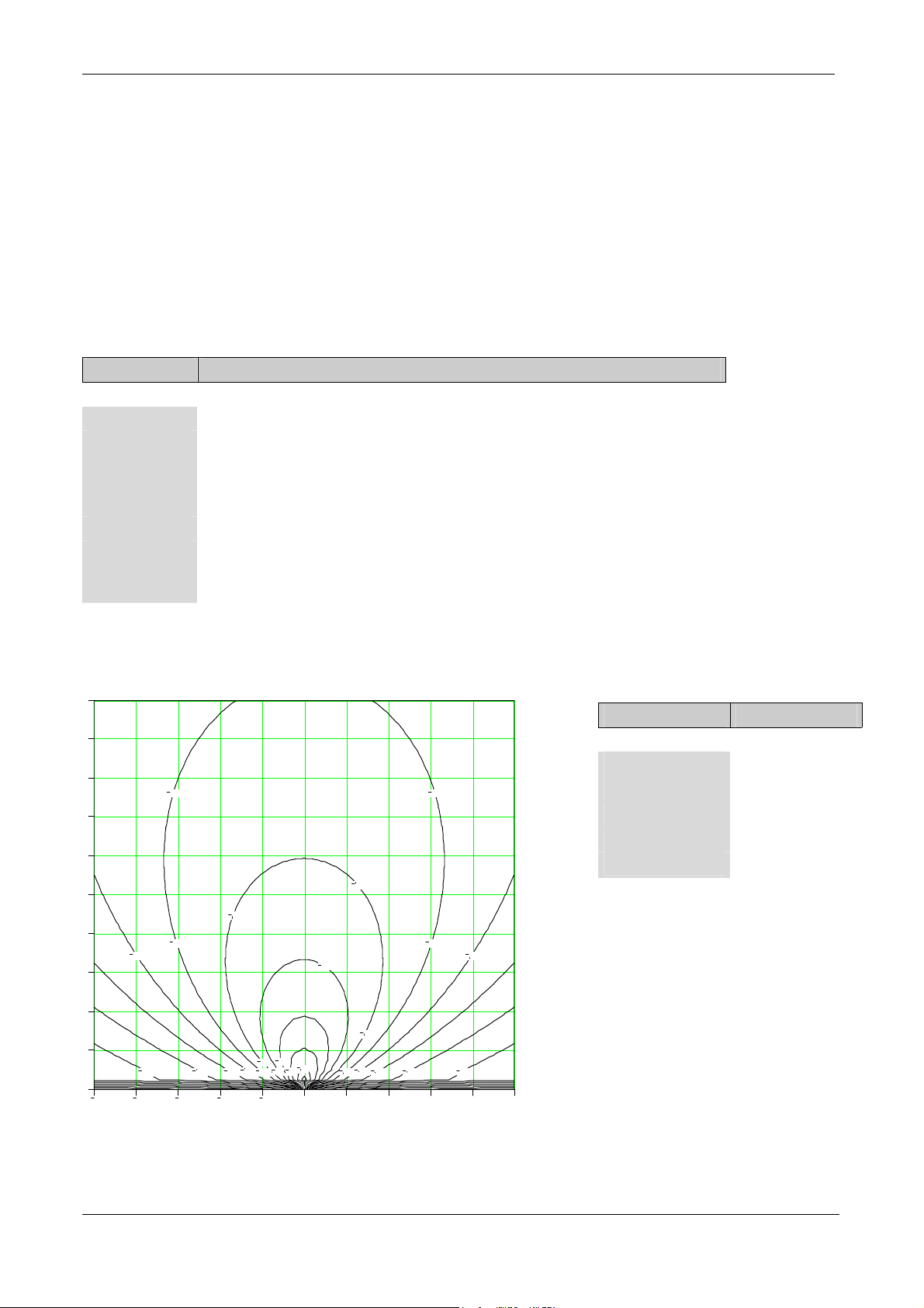
In the following diagrams a contour plot is shown of the received label signal. This contour plot gives always the
top view of the situation. The position of the reader is always at 0,0. The label is positioned in a area of 10 by 10
meter. The scale of the plot is such that every square has a dimension of 1 by 1 meter. The minimum signal
needed from the label is –100 dBm. This means that the area inside the –100 dBm contour represents the
detection area.
The following parameters are used within the examples:
Parameter Description.
R-height Mounting height of the TRANSIT reader with respect of the ground.
D-angle Angle over which the reader is rotated in the vertical plane. When D-angle is
0 degrees the reader ‘looks’ parallel to the ground. When D-angle is 90
degrees the reader is ‘looking’ straight down.
A-angle Angle over which the reader is rotated in the horizontal plane.
L-height Mounting height of the transponder with respect to the ground.
L-angle Angle over which the label is rotated in the vertical plane. When L-angle is 90
degrees the label is ‘looking’ parallel to the ground. When L-angle is 0 degrees
the label ‘looks’ straight up.
4.6.2 Example 1.
10
9
8
7
6
5
4
3
2
1
0
Rpow
Received power : -100 dBm minimum
100
90
90
100
110
90
110
100
120
140
5
4
130
3
2
1
80
90
70
50
60
80
0
110
100
120
1
100
100
110
130
2
140
3
4
Parameter Value
R-height 1
D-angle
A-angle
0°
0°
L-height 1
L-angle
90°
This example shows the ideal situation the
reader is positioned at the same height as the
label. This figure can be used for approaching
labels as for labels passing at certain distance
in front of the reader.
5
© NEDAP IDEAS – AVI P.O. Box 103, NL-7140 AC GROENLO Page 34-41
Page 35
Version: 1.0, September 19, 2002 4 – APPLICATION INFORMATION
4.6.3 Example 2.
10
140
9
8
7
130
6
5
4
120
120
110
3
130
2
140
150
1
0
5 4 3 2 1 0 1 2 3 4 5
Rpow
Received power : -100 dBm minimum
130
120
110
100
90
100
90
120
130
150
140
110
110
120
100
130
120
110
120
130
140
150
160 160 170 170 180 180 190 190
140
Parameter Value
R-height 3
D-angle
A-angle
L-height 1
L-angle
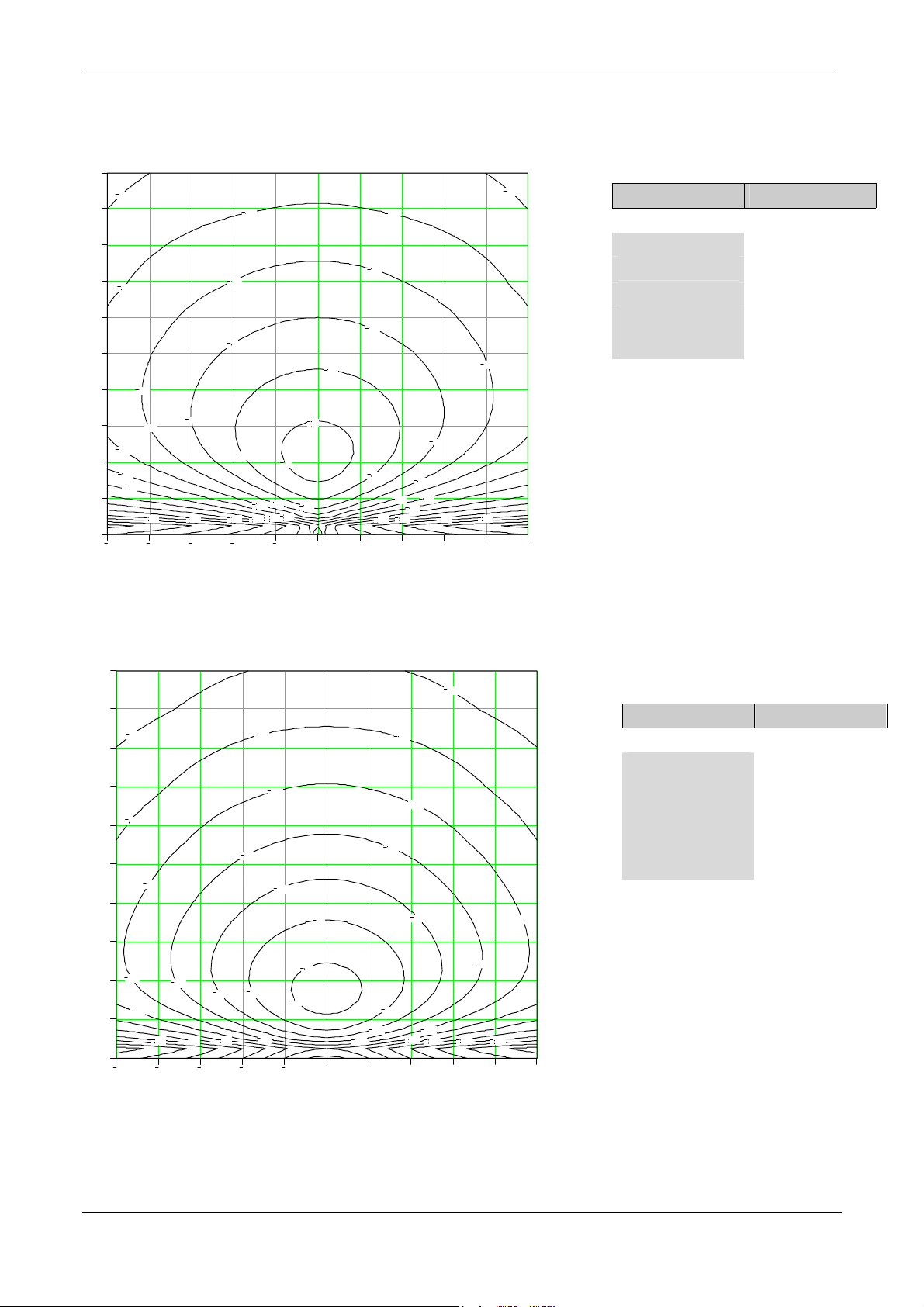
By placing the reader on a height of 3
meters and not adjusting the vertical angle
of the label, we see a strong reduction in
the detection area.
45°
0°
90°
4.6.4 Example 3.
10
9
140
8
Received power : -100 dBm minimum
130
140
130
Parameter Value
R-height 3
7
6
5
4
3
2
1
0
5
Rpow
120
130
110
120
100
90
120
110
100
By letting the label look up 45° the
120
detection area increases. Due to the
110
80
120
110
130
160
150
90
100
140
80
120
90
120
100
110
130
140
160
150
reader D-angle of 45° at a height of 3
meters and a label height of 1 meter the
maximum of energy is approximately 2
meters before the reader. This maximum
could be placed much further out to
improve the detection area.
5
4
3
2
1
0
1
2
3
4
D-angle
A-angle
45°
0°
L-height 1
L-angle
45°
© NEDAP IDEAS – AVI P.O. Box 103, NL-7140 AC GROENLO Page 35-41
Page 36
Version: 1.0, September 19, 2002 4 – APPLICATION INFORMATION
4.6.5 Example 4.
10
9
8
7
6
5
4
3
2
1
0
Rpow
Received power : -100 dBm minimum
110
105
110
115
120
125
135
145
150
160
180
175
165
5
140
155
170
160
155
3
4
105
100
100
95
100
95
105
110
115
130
135
145
140
150
2
90
90
95
100
110
125
120
125
115
110
130
120
1
105
1
0
105
110
105
100
110
115
105
120
120
135
145
115
125
140
130
125
130
135
145
140
150
3
2
160
155
175
170
160
155
165
4
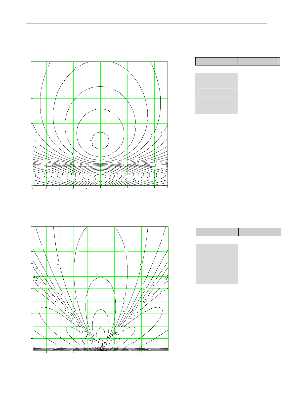
By reducing the reader down look angle (D-
150
angle) to 15° the range is again improved.
180
5
Parameter Value
R-height 3
D-angle
A-angle
15°
0°
L-height 1
L-angle
45°
4.6.6 Example 5.0
10
9
8
7
6
5
4
3
2
1
0
Rpow
Received power : -100 dBm minimum
120
110
140
160
150
140
130
5
150
130
160
150
140
4
100
120
140
150
150
130
3
90
100
110
80
140
130
130
120
110
120
100
1
2
70
80
90
90
60
0
100
110
150
120
130
90
100
110
150
140
130
120
130
130
130
110
120
100
2
1
160
140
150
140
4
3
Parameter Value
120
R-height 1
D-angle
A-angle
140
160
160
150
140
L-height 1
L-angle
130
This example shows the detection area
when the TRANSIT reader is placed 90
degrees rotated. This means that the smaller
beam width is in the horizontal plane. This
results in a much narrower detection area
which can be necessary in certain
applications.
5
0°
0°
90°
© NEDAP IDEAS – AVI P.O. Box 103, NL-7140 AC GROENLO Page 36-41
Page 37
Version: 1.0, September 19, 2002 4 – APPLICATION INFORMATION
4.6.7 Example 6.
10
9
8
7
6
5
4
3
2
1
0
Rpow
150
155
160
165
180
175
165
160
155
150
145
140
135
130
125
120
115
110
110
5
170
170
105
100
105
3
4
Received power : -100 dBm minimum
145
150
155
160
165
165
160
155
150
145
140
135
130
125
120
115
110
100
95
95
2
105
0
1
145
150
155
160
165
170
165
160
155
150
145
140
135
130
125
120
115
110
175
170
Parameter Value
180
R-height 8
D-angle
A-angle
90°
0°
L-height 1
L-angle
0°
105
100
95
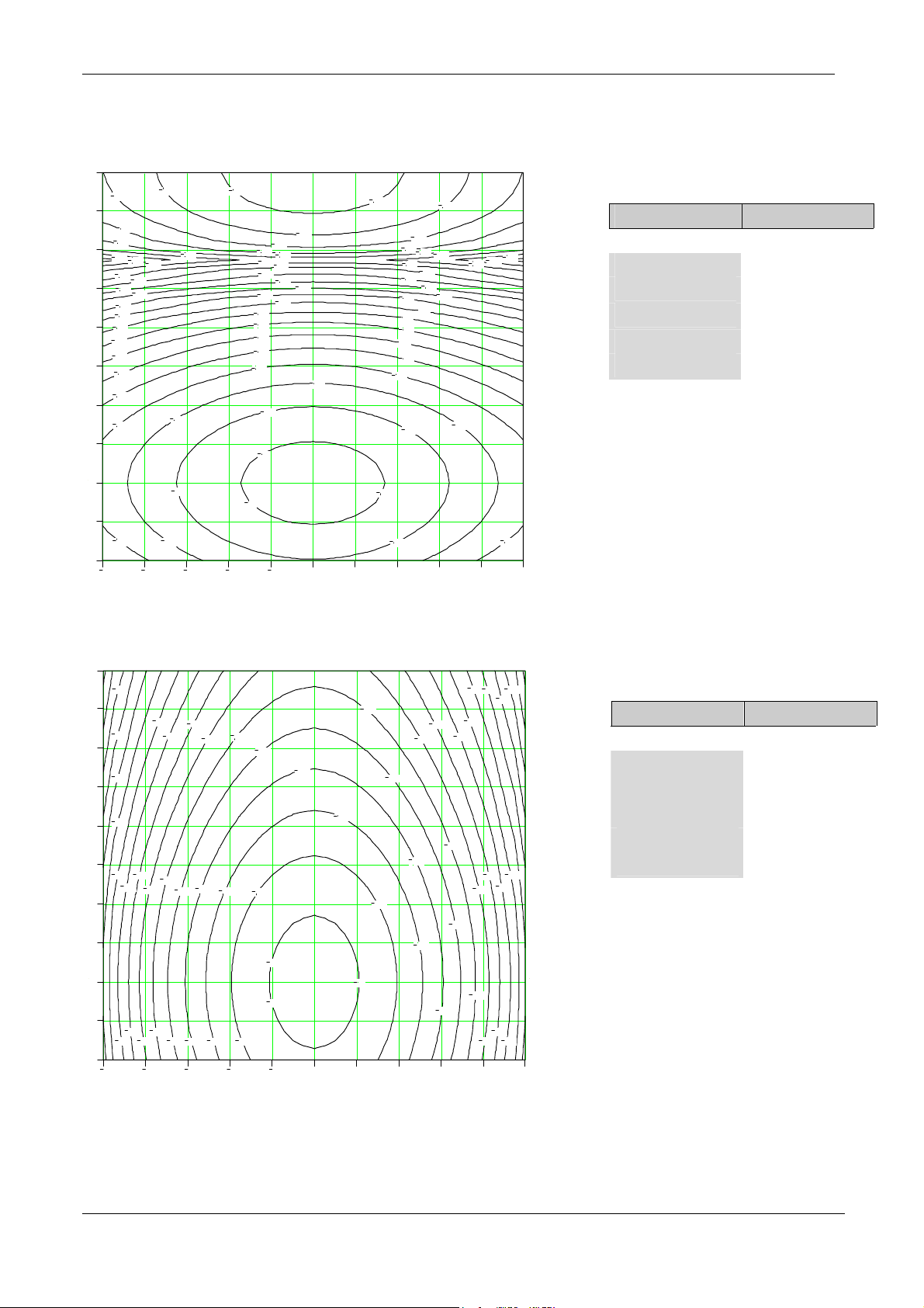
This is a situation were the reader sits on
the ceiling 8 meters above a door. The
reader position is 0, 2. The labels is at a
110
100
3
2
1
height of 1 meter and is looking straight up.
5
4
4.6.8 Example 7.
10
9
8
7
6
5
4
3
2
1
0
Rpow
Received power : -100 dBm minimum
145
160
120
140
130
155
150
145
140
130
135
130
135
125
5
135
120
125
115
120
115
3
4
120
125
110
110
105
115
110
105
100
95
95
100
0
1
2
125
115
105
110
100
105
95
2
1
150
140
130
135
120
130
125
115
120
110
130
125
4
3
160
155
Parameter Value
R-height 8
D-angle
A-angle
L-height 1
140
135
L-angle
This is a situation were the reader sits on
the ceiling 8 meters above a door. The
reader position is 0, 2. The labels is at a
height of 1 meter and is looking straight up.
The difference with example 6 is that the
reader is rotated 90 degrees to make use of
135
the smaller beam width
5
90°
0°
0°
© NEDAP IDEAS – AVI P.O. Box 103, NL-7140 AC GROENLO Page 37-41
Page 38
Version: 1.0, September 19, 2002 4 – APPLICATION INFORMATION
4.6.9 Example 8.
10
9
8
Received power : -105 dBm minimum
100
105
110
Parameter Value
R-height 3
7
6
5
95
100
105
110
115
120
D-angle
A-angle
15°
30°
L-height 1.25
L-angle
60°
4
3
2
1
0
Rpow
90
95
100
120
115
110
135
135
135
115
120
110
0
1
90
95
105
125
130
140
145
150
170
2
3
105
100
110
115
120
4
125
130
135
140
5
115
125
120
130
135
140
145
6
7
150
8
9
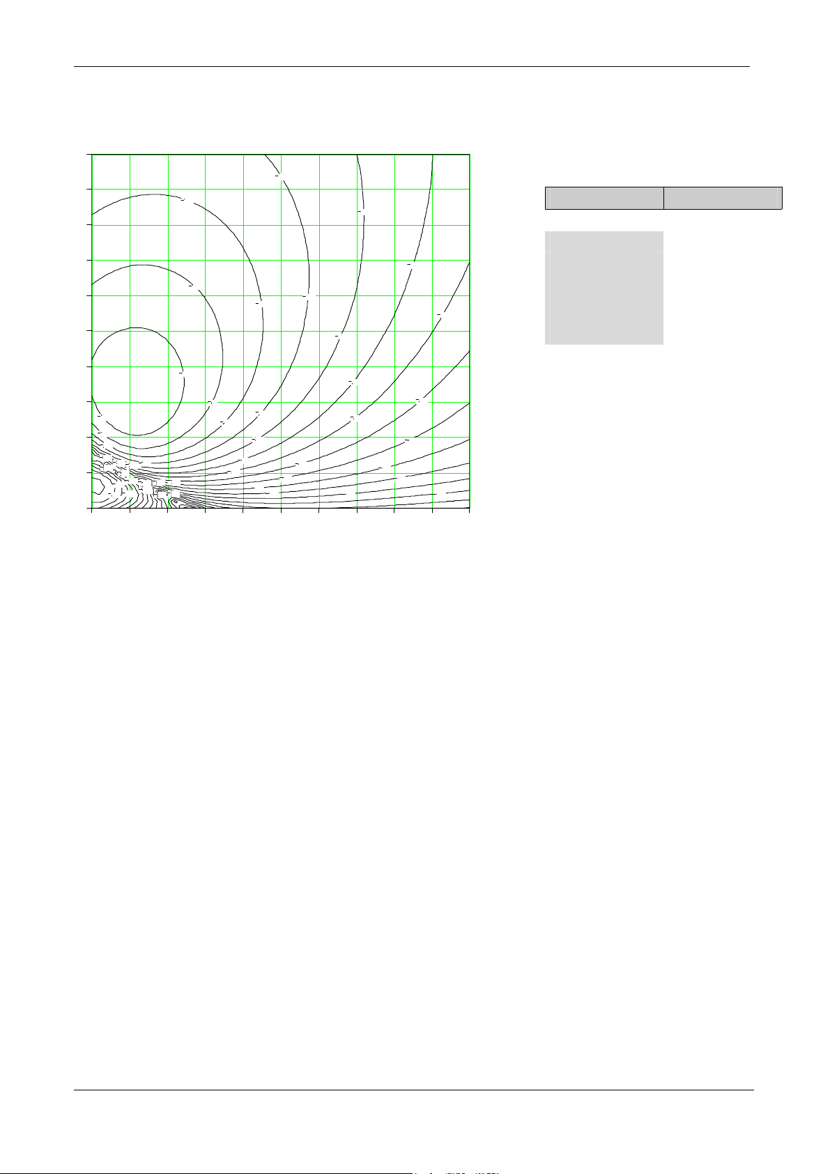
This example is typical for the situation
where a label is behind the windshield of a
car and the reader is placed along the road.
The reader is rotated 30° towards the road
in the horizontal plane.
10
© NEDAP IDEAS – AVI P.O. Box 103, NL-7140 AC GROENLO Page 38-41
Page 39
Version: 1.0, September 19, 2002 4 – APPLICATION INFORMATION
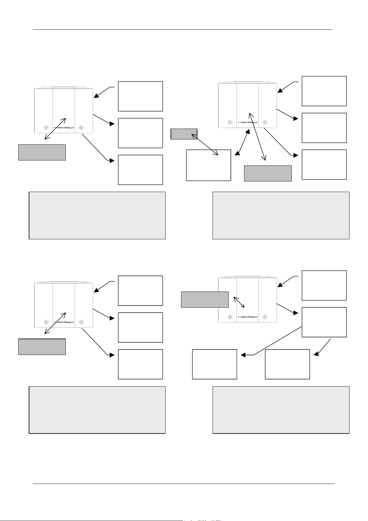
4.7 Typical configurations.
120 Vac or
24 Vdc
Communication
to Host
Transponder
Internal relay
controls gate
STAND ALONE
• Use of short authorization table possible.
• Profi-Bus or InterBus S network
connection optional.
Inductive
antenna
120 Vac or
24 Vdc
Communication
to Host
Internal relay
controls gate
Transponder
GATE MASTER
• Use of short authorization table possible.
• Reflex 130 as inductive antenna
• GATE MASTER firmware needed!
120 Vac or
Communication
WIN-GATE
Transponder
Internal relay
controls gate
TRANSIT Extended
• Max. 1000 tag’s in authorization table.
• Slave in multi drop loop. (32 slaves max)
• Loop control by means of WIN-GATE.
24 Vdc
to Host
Transponder
Internal relay
controls gate
• Max. 100.000 tag’s in authorization table.
• TRANSIT connected to antenna input.
• Connection to any inductive reader possible.
120 Vac or
24 Vdc
Inductive Nedap
reader.
(Accessor III)
Communication
to Host
WinXS
TRANSIT
© NEDAP IDEAS – AVI P.O. Box 103, NL-7140 AC GROENLO Page 39-41
Page 40

Version :- 1.0 September 19, 2002 Appendix A – Technical specification
Appendix A Technical specification
Item Specification Remarks
Housing Stainless steel
Dimensions 310 x 107 x 245
Weight < 5 kg
Protection class IP 65
Temperature
-30°C .. +55°C
operational
Temperature storage
-40°C .. +85°C
Relative humidity 10 .. 93% non-condensing.
Identification range Typical 10 meters Tag in line of sight.
Object speed 200 km/h Identification trajectory > 5 meter, 64 bit tag
Power supply 120 Vac +/- 10%, 200 mA, 50/60 Hz
24 Vdc +/- 10 %, 500 mA
Power consumption 30 VA (TRANSIT Extended)
only.
DC supply shall be capable of delivering a 1 A
inrush current.
18 VA (TRANSIT)
Frequency range 2438.4 MHz .. 2457.0 MHz Selected by DIP-switch, sealed in factory.
Number of channels 32
Channel spacing 600 kHz To be used when systems are close together.
Polarization Circular (LHC)
EIRP Max 18.7 dBm linear
Receiver sensitivity -100 dBm
Antenna gain > 8 dBi Valid for RX-array and TX-array
EMC In accordance with the 89/336/EEC
European directive
EN 50081-1, EN 50082-1
EN 50082-2, ETS 0908
Safety EN 60950
Complies to the
following regulations
FCC Part 15.245
ETS 300 440
© NEDAP IDEAS – AVI P.O. Box 103, NL-7140 AC GROENLO Page 40-41
Page 41

Version : 1.0 September 19, 2002 Appendix B – Nedap part numbers.
Appendix B Nedap part numbers.
ITEM Part number Description
• TRANSIT
• TRANSIT
Extended
• Booster XS-
card
• Booster ISO-
card
• Window tag
R/O.
• Window tag
R/W.
• Switched
Window tag
R/O
• Switched
Window tag
R/W
• Heavy duty tag
R/O
• Heavy duty tag
R/W 6
• Heavy duty tag
R/W 80
• Combi Booster
ISO
• Combi Booster
LCC
• Pocket-tag
R/O
• Pocket-tag
R/W 6
• RS 232 III
• CM422
• Current loop II
• Profi-Bus DP
• InterBus
9874801 Microwave identification system in stainless steel housing.
9873694 Microwave identification system in stainless steel housing
intended for access control.
9848827 Tag which can be placed behind the windshield of a vehicle and in
which a thick inductive card can be placed. Activation after
pressing the card.
9848819 Tag which can be placed behind the windshield of a vehicle and in
which a thin inductive card can be placed. Activation after
pressing the card.
9862897 Tag which can be placed behind the windshield of a vehicle. This
tag is always active. Number is factory programmed.
9866078 Tag which can be placed behind the windshield of a vehicle. This
tag is always active. This tag can also be read and programmed
inductively.
9866094 Tag which can be placed behind the windshield of a vehicle. This
tag is only active for a short time after activation by the driver.
Number is factory programmed.
9866086 Tag which can be placed behind the windshield of a vehicle. This
tag is only active for a short time after activation by the driver.
This tag can also be read and programmed inductively.
9875689 This tag is a heavy-duty tag that can be mounted at the outside of
many vehicles and is capable of exposure to harsh environmental
conditions. This tag has an EX approval (Eex ia IIC T4) Number
is factory programmed.
9849289 Programmable with 6 decimal number by customer. 64 bit frame
length including customer code.
9875697 Programmable with 20 hexadecimal numbers by customer. 128-
bit frame length
NO customer code.
9884025 This tag combines the functionality of a Window Tag and a
Booster. Vehicle-ID is fixed programmed into the CombiBooster. There are a number of operational modes. See CombiBooster manual.
9894017 As Combi Booster ISO but can hold the thicker XS-cards.
9882170 Credit Card sized microwave and inductive readable tag intended
for identifying people. Uses simple multi tag protocol.
9881670 Credit Card sized microwave and inductive readable tag intended
for identifying people. Uses simple multi tag protocol.
Programmable with 6 decimal number by customer. 64 bit frame
length including customer code.
7806434 Optional communication board.
7811730 Optional communication board. (RS422)
7803940 Optional communication board.
7817134 Optional communication board for Profi-Bus networks.
7817169 Optional communication board for InterBus networks.
© NEDAP IDEAS - AVI 41-41
Page 42
P61 firmware
for TRANS-IT (PS-270)
Installation Guide
®
28 June 2002 Part.no. 5268397
This information is furnished for guidance, and with no guarantee as to its accuracy or completeness; its publication
conveys no licence under any patent or other right, nor does the publisher assume liability for any consequence of its
use; specifications and availability of goods mentioned in it are subject to change without notice; it is not to be
reproduced in any way, in whole or in part, without the written consent of the publisher.
© Nedap IDEAS, P.O. Box 103, NL-7140 AC GROENLO Page 1 of 18
Page 43

P61 firmware
CONTENTS
1 INTRODUCTION..........................................................................................................................3
2 DIP SWITCH SETTINGS .............................................................................................................. 4
3 LED INDICATORS.......................................................................................................................4
4 APPLICATION INFORMATION......................................................................................................5
4.1 DC2/DC4 PROTOCOL........................................................................................................ 5
4.1.1 EVENT MESSAGES............................................................................................... 5
4.1.2 COMMAND MESSAGES.........................................................................................7
5 FIRMWARE UPGRADING.......................................................................................................... 12
6 FIRMWARE REVISION HISTORY............................................................................................... 12
A HARDWARE ............................................................................................................................. 13
B ASCII TABLE............................................................................................................................ 14
C DC2/DC4 PROTOCOL ............................................................................................................... 15
C.1 DATA FORMAT................................................................................................................ 15
C.2 PROTOCOL DESCRIPTION.............................................................................................. 15
C.3 SPECIAL CHARACTERS ................................................................................................. 15
C.4 DATA MESSAGE............................................................................................................. 16
C.5 CHECKSUM CALCULATION............................................................................................. 16
C.6 FLOWCHART.................................................................................................................. 17
D DECIMAL TO ASCII CONVERSION TABLE................................................................................. 18
© Nedap IDEAS, P.O. Box 103, NL-7140 AC GROENLO Page 2 of 18
Page 44

P61 firmware
1 INTRODUCTION
The P61 firmware is the standard TRANS-IT® (PS-270) firmware.
The TRANS-IT® is based on proven microwave technology in the 2.45 GHz ISM band and allows
identification of tags at a distance up to 10 meters, even at high speeding passage. The P61 firmware
combines microwave identification with inductive identification at 120 kHz.
The P61 firmware supports a wide range of transponders for various applications. The heavy duty tag is
developed typical for vehicle applications. The window-tags can be mounted easily behind the windshield of
a vehicle. The booster-unit is a special window tag, which is able to hold a NEDAP inductive identification
card. This card is read by the booster. The combi-booster combines the features of the window-tag with a
booster allowing to identify both vehicle and driver.
The P61 firmware supports the DC2/DC4 asynchronous communication protocol. This ASCII based
communication protocol supports software handshaking and error checking. Identified transponders are
automatically reported to any connected host computer in an event message, therefore no polling is
required.
Below the main features of the P61 firmware are summarised:
• Supports DC2/DC4 communication protocol
• Identifies microwave 2.45GHz transponders and (if enabled) inductive 120kHz transponders.
• Decodes NEDAP PM-transponders, NEDAP Combi-Boosters and EM Marin 400x transponders.
© Nedap IDEAS, P.O. Box 103, NL-7140 AC GROENLO Page 3 of 18
Page 45
P61 firmware
2 DIP SWITCH SETTINGS
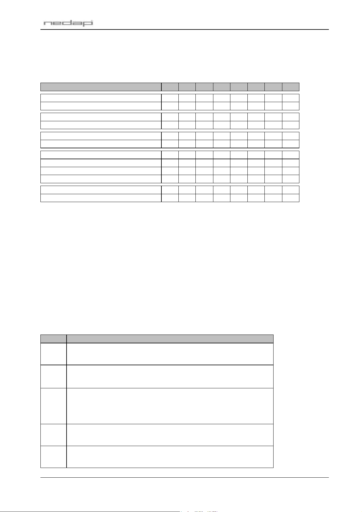
The TRANS-IT® (PS-270) has 8 DIP-switches, which are used by the P61 firmware as described in the
table below. Refer to appendix A when locating the DIP-switches.
VALUE 8 7 6 5 4 3 2 1
Use default antenna ON x x x x x x x
Microwave and inductive antenna OFF x x x x x x x
Framelength 128 bit x ON x x x x x x
Framelength 64 bit x OFF x x x x x x
Manchester decoding disabled x x ON x x x x x
Manchester decoding enabled x x OFF x x x x x
Baudrate 9600 x x x ON ON x x x
Baudrate 1200 x x x ON OFF x x x
Baudrate 19200 x x x OFF ON x x x
Baudrate 38400 x x x OFF OFF x x x
Data format 7/even/1 x x x x x ON x x
Data format 8/none/1 x x x x x OFF x x
Table 1: DIP-switch settings
Note1: Set DIP-switch 8 only to OFF when using a TRANS-IT® reader with an inductive (120kHz) antenna connected.
The P61 firmware then tries to identify transponders on both antennas (microwave and inductive). When on
one antenna a valid transponder is identified it sticks to that antenna source and does not identify anymore on
the other antenna. So, when a vehicle is identified with the microwave antenna and this vehicle stays in front of
the TRANS-IT®, nobody is identified at the inductive antenna.
When identifying vehicles at high speed it is recommended to keep DIP-switch 8 in ON position.
Note2: Set DIP-switch 7 to OFF when no combi-booster or EF-coded transponders are to be identified. This
increases the detection speed. DIP-switch 7 is only read during a startup.
Note3: Set DIP-switch 6 to OFF when manchester encoded transponders (e.g. EM Marin 400x) are to be identified.
3 LED INDICATORS
A number of LED's are used by the P61 firmware to indicate the current status. The table below describes
the function of each LED. Refer to appendix A when locating the LED's.
LED Description
STS Status LED.
Indicates that the power is on and the processor is running. The LED continuously
blinks like the system's heartbeat.
ID Identification LED.
This green LED starts to blink fast when a valid transponder is identified.
The LED stays off when no (valid) transponder is identified.
UL Unlock LED.
The unlock LED is normally off and goes on when a valid transponder is identified. The
LED is turned off when no transponder is identified anymore and the relay-hold-time
has elapsed. This LED can be connected to a Reflex or DC130 antenna.
There is also a relay contact present which has the same function.
NA Lock LED.
Red LED indicating system standby. This LED is normally on and goes off when the
unlock LED goes on. This LED can be connected to a Reflex of DC130 antenna.
INP /
DOOR
Table 2: LED indicators
Input status LED
This red LED is on when the input contact is closed. The input is not used in the P61
firmware.
© Nedap IDEAS, P.O. Box 103, NL-7140 AC GROENLO Page 4 of 18
Page 46

P61 firmware
4 APPLICATION INFORMATION
The main function of the reader is to detect NEDAP transponders and to transmit its identification number
to a host computer. The id-number will be sent to the host in a so-called event message. A detailed
description of each event message is given in chapter 4.1.1.
Command messages allow a host computer to change settings in the reader or to request information from
the reader. The command messages are described in chapter 4.1.2.
4.1 DC2/DC4 PROTOCOL
DC2/DC4 protocol is the standard Nedap protocol which supports two-way communications, error checking
and software handshaking.
This chapter describes the application layer of the DC2/DC4 protocol as it is implemented in the P61
firmware. Refer to appendix C for a description of the DC2/DC4 protocol details.
4.1.1 EVENT MESSAGES
Event messages are messages that report to the host computer that a specific event has occurred inside
the reader. There are different types of event messages that may be send by the reader, like the detection
event that is sent when a transponder is identified.
Event messages, when they occur, are stored locally in the reader in the event buffer. Once
communication is idle the reader will try to transmit the event message. A maximum of 3 event messages
can be stored. When the event buffer is full a new event will overwrite the oldest one. The event buffer is
located in RAM memory and its contents will be lost when the power is off.
The reader may send the following event messages. Protocol dependant characters are not shown here.
Spaces are added for clarity.
Spaces are only added for readability.
O-event: Reader restarted
Description: The reader sends this event message as soon as the reader is powered-up to
indicate that the system is active. Application settings stored in EEPROM were
not lost.
Syntax: 01 01 01 20 O [????????]
Where: [????????] Optional unused timestamp. Can be enabled with command
message 0265.
Notes: In case the P-event is sent the O-event is omitted.
P-event: Reader reset
Description: The reader sends this event message as soon as the reader is powered-up to
indicate that the system is active. Application settings stored in EEPROM were
reset to their factory default. EEPROM settings are not lost when the reader is
switched off. The EEPROM settings may be lost when the firmware is changed.
Syntax: 01 01 01 20 P [????????]
Where: [????????] Optional unused timestamp. Can be enabled with command
message 0265.
Notes: In case the P-event is sent the O-event is omitted.
© Nedap IDEAS, P.O. Box 103, NL-7140 AC GROENLO Page 5 of 18
Page 47
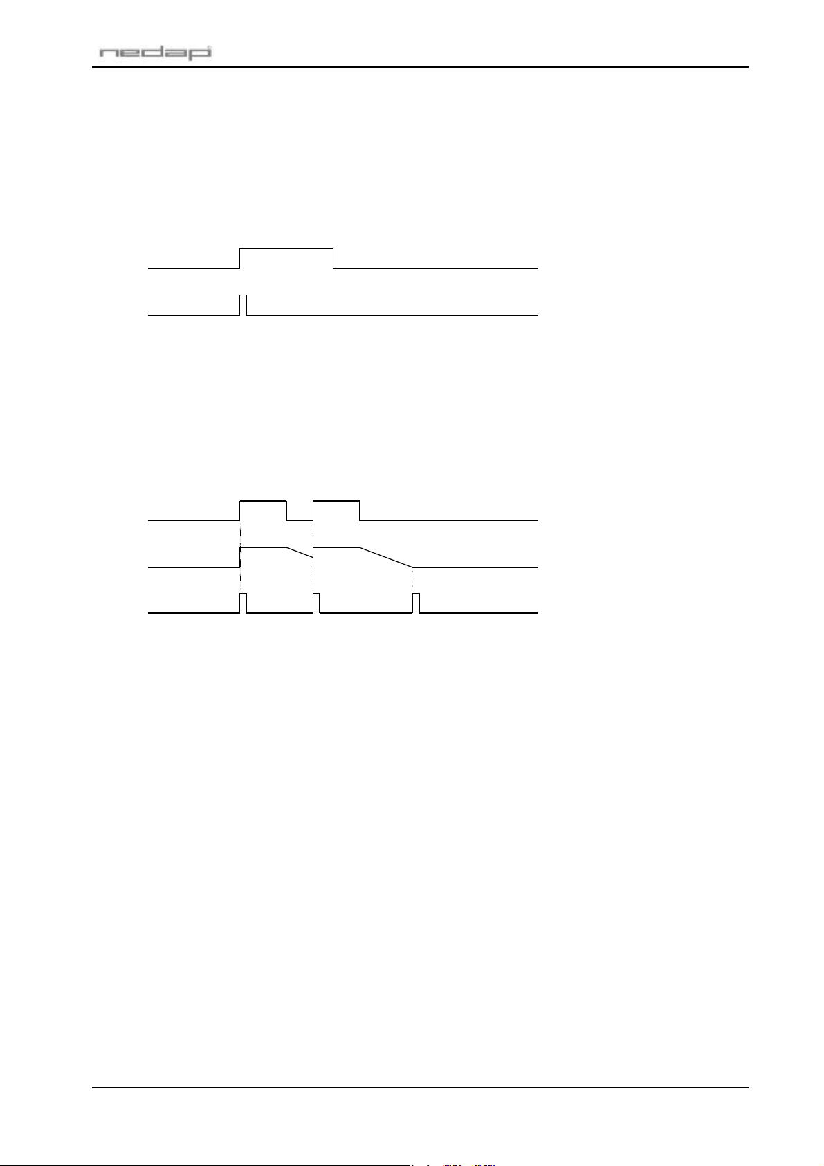
N-event: Transponder identified (6-digit CF/DF/GF-code)
Description: When a transponder is identified this event message reports its identification
number. This event is only sent when a 6-digit transponder is identified. See also
the timing diagram in Figure 1.
Syntax: 01 01 01 20 N [????????] nnnnnn
Where: [????????] Optional unused timestamp. Can be enabled with command
message 0265.
nnnnnn Identification number in range from 1 to 999999.
Detection
Event message
Figure 1: Timing diagram detection event
N-event: End of detection (6-digit CF/DF/GF-code)
Description: This event message is transmitted when a previously identified transponder is no
longer present. The event is not send until the holdtime has expired.
Syntax: 01 01 01 20 N [????????] 000000
Where: [????????] Optional unused timestamp. Can be enabled with command
message 0265.
Notes: Not every detection event has to be followed by a end-of-detection event. See the
timing diagram in Figure 2.
P61 firmware
Detection
Holdtime
Event message
ID-1 ID-2
ID-1 ID-2 End-of-detection
Figure 2: Timing diagram end-of-detection event
U-event: Combi-booster identified
Description: When a combi-booster is identified this event message reports both identification
numbers. The first identification number is from the combi-booster, the second
number is from the card which may be placed in the combi-booster.
Syntax: 01 01 01 20 U [????????] 0000aaaaaa bbbbbbbbbb
Where: [????????] Optional unused timestamp. Can be enabled with command
message 0265.
aaaaaa Combi-booster identification number in range from 1 to 999999.
bbbbbbbbbb Card identification number. Can be hexadecimal if a EM-Marin 400x
transponder card is used.
Notes: When no card is placed in the combi-booster the second identification number is
left blank (filled with zeros).
U-event: Transponder identified (80-bit EF-code)
Description: When a transponder is identified this event message reports its identification
number. This event is only sent when an 80-bit transponder is identified.
Syntax: 01 01 01 20 U [????????] xxxxxxxxxxxxxxxxxxxx
Where: [????????] Optional unused timestamp. Can be enabled with command
message 0265.
xxx...xxx Identification number 80 bit hexadecimal.
x Hexadecimal character made out of 4 bits (nibble) added with the
value of character '0'.
© Nedap IDEAS, P.O. Box 103, NL-7140 AC GROENLO Page 6 of 18
Page 48

U-event: EM-Marin 400x transponder identified
Description: When a EM-Marin 400x transponder is identified this event message reports its
identification number.
Syntax: 01 01 01 20 U [????????] 0000000000 xxxxxxxxxx
Where: [????????] Optional unused timestamp. Can be enabled with command
message 0265.
Notes: The EM-Marin 400x transponder may be identified by the inductive antenna (if
enabled by DIP-switch 8) or by the microwave antenna when placed in a booster.
U-event: End of detection
Description: This event message is transmitted when a previously identified transponder is no
longer present. The event is not send until the holdtime has expired.
Syntax: 01 01 01 20 U [????????] 00000000000000000000
Where: [????????] Optional unused timestamp. Can be enabled with command
message 0265.
Notes: Not every detection event has to be followed by a end-of-detection event. See the
timing diagram in Figure 2.
4.1.2 COMMAND MESSAGES
P61 firmware
The following command messages may be sent to the reader. Protocol dependent characters are not
shown here.
20 Check communication
Description: Command message can be used to check the communication with the TRANS-IT.
The TRANS-IT will always respond with an ACK.
Syntax: 01010120
Reply: -
0243 Request reader status
Description: Request the current status of the reader. The reply message contains the
transponder identification number.
Syntax: 0101010243
Reply: 0101010243nnnnnn or 0101010243xxxxxxxxxxxxxxxxxxxx
Where: nnnnnn Identification number 6-digit in range from 0 to 999999.
xxx...xxx Identification number 80 bit hexadecimal.
Example1: Window-tag number 12345
reply = 0101010243012345
Example2: Combi-booster number 666666 with no inductive card
reply = 010101024300006666660000000000
Example3: Combi-booster number 666666 with Em-Marin card 0100F246A8
reply = 010101024300006666660100?246:8
Example4: Booster with Em-Marin card 0100F246A8
reply = 010101024300000000000100?246:8
0293 Request firmware version
Syntax: 0101010293
Reply: 0101010293pppvvv
Where: ppp Firmware name (P61).
vvv Firmware Version (100 = version 1.00).
© Nedap IDEAS, P.O. Box 103, NL-7140 AC GROENLO Page 7 of 18
Page 49

0250 Clear event buffer
Description: Erase all events from the event buffer. Events are automatically erased from the
Syntax: 0101010250
Reply: -
0263 Restart reader
Description: Restart the reader. This is the same as turning the power-off and back on again,
Syntax: 01010163[W]
or: 0101010263[W]
Reply: Where: [W] Optional unused parameter to accept message compatible with other
Notes: See command message 02<>.
P61 firmware
event buffer when they are transmitted to the host computer. But it may be useful
to clear the event buffer when the host computer has been offline for a while to
remove 'old' events.
and will therefore be followed by an O-event (reader restart). All EEPROM settings
are unaffected by this command.
NEDAP readers.
02<> Reset reader
Description: Restart the reader and reset all EEPROM settings to their factory defaults. The
Syntax: 01010102<>[W]
Reply: Where: W Optional unused parameter to accept messages compatible with
Notes: See command message 0263.
reader will generate a P-event (reader reset).
other NEDAP readers.
© Nedap IDEAS, P.O. Box 103, NL-7140 AC GROENLO Page 8 of 18
Page 50
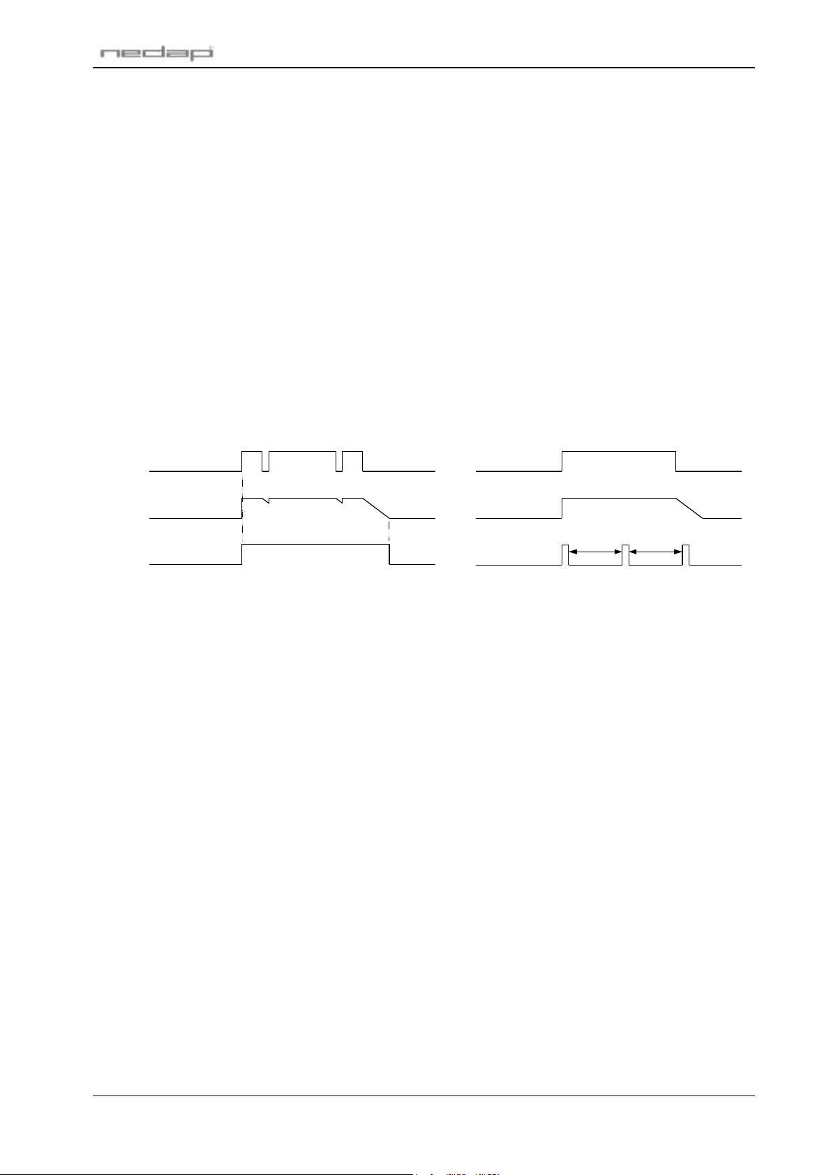
0255 Request timers
Description: Request timer values. Changed timer values are stored in EEPROM and are only
Syntax: 0101010255
Reply: 0101010255AABBCCDD
Where: AA Relay hold time in the range from 1 to 255 tenths of seconds. Use
P61 firmware
lost when a 'reset reader' command is performed.
The relay hold time (also referred to as the unlock-time) is default 1 second. It
causes the unlock relay to stay activated for the specified time after the
transponder could not be identified anymore. See timing diagram in Figure 3.
When during the relay hold time the same transponder is identified again the
reader will not generate a new detection event.
The repeat time is default 0 seconds, which means that the detection event is
only sent once. The repeat time causes the reader to transmit an detection event
every 'repeat time' seconds for as long as the transponder is present. See timing
diagram in Figure 4.
decimal to ASCII conversion table.
BB Unused parameter (reserved for alarm time).
CC Unused parameter (reserved for blocking time).
DD Repeat time in the range from 0 to 255 tenths of seconds. Use
decimal to ASCII conversion table.
Detection
Holdtime
Relay
Figure 3: Timing diagram relay-hold-time Figure 4: Timing diagram repeat time
0256 Set timers
Syntax: 0101010256TTT
or: 0101010256AA[BB[CC[DD]]]
Reply: Where: TTT Relay hold time in the range from 001 to 025 seconds.
Notes: See command message 0255.
Detection
Holdtime
Event message
AA Relay hold time in the range from 1 to 255 tenths of seconds. Use
T-Repeat T-Repeat
decimal to ASCII conversion table.
BB Unused parameter (reserved for alarm time).
CC Unused parameter (reserved for blocking time).
DD Repeat time in the range from 0 to 255 tenths of seconds. Use
decimal to ASCII conversion table.
When only the relay hold time has to be changed, the other timer values do not
have to be specified.
© Nedap IDEAS, P.O. Box 103, NL-7140 AC GROENLO Page 9 of 18
Page 51

0265 Set 'time in event message' mode
Description: Enables or disables the optional dummy timestamp characters in event
messages. This setting is stored in EEPROM and is only lost when a 'reset reader'
command is performed.
Syntax: 0101010265m
Reply: Where: m 0 = disabled (default). Dummy timestamp characters in event
messages will not be transmitted.
1 = enabled. Dummy timestamp characters in event messages are
transmitted.
0266 Request 'time in event message' mode
Syntax: 0101010266
Reply: 0101010266m
Where: m 0 = disabled (default).
1 = enabled.
Notes: See command message 0265.
0267 Set 'end-of-detection' mode
Description: The end-of-detection event is a detection event with identification number 0. This
event is only send when the relay-hold time has expired. See timing diagram in
Figure 2. This setting is stored in EEPROM and is only lost when a 'reset reader'
command is performed.
Syntax: 0101010267m
Reply: Where: m 0 = end-of-detection event message disabled (default).
1 = end-of-detection event message enabled.
Notes: See command message 0255.
P61 firmware
0268 Request 'end-of-detection' mode
Syntax: 0101010268
Reply: 0101010268m
Where: m 0 = end-of-detection event message disabled (default).
1 = end-of-detection event message enabled.
Notes: See command message 0267.
© Nedap IDEAS, P.O. Box 103, NL-7140 AC GROENLO Page 10 of 18
Page 52

0270 Set relay activation mode
Description: Set relay activation mode to manual or automatic. In ma nual mode the relay is
only controlled by the command messages 0272, 0274 and 0276. In automatic
mode the relay is also activated when a transponder is identified.
This setting is stored in EEPROM and is only lost when a 'reset reader' command
is performed. Changing the relay activation mode updates the relay output status
if necessary.
Syntax: 0101010270m
Reply: Where: m 0 = automatic (default). Relay will be activated and de-activated
0271 Request relay activation mode
Syntax: 0101010271
Reply: 0101010271m
Where: m 0 = automatic (default). Relay will be activated and de-activated
Notes: See command message 0270.
P61 firmware
when transponders are identified.
1 = manual. Relay is only activated and de-activated with command
messages 0272, 0274 and 0276.
when transponders are identified.
1 = manual. Relay is only activated and de-activated with command
messages 0272, 0274 and 0276.
0272 Activate relay
Description: Activate unlock relay.
The relay will not be de-activated until command message 0274 is received.
When relay activation mode is automatic (default setting) the relay is activated
when either this command is sent or a transponder is identified. When this
command is sent the relay stays activated, also when there is no more detection.
See also command 0270 to change the relay activation mode.
Syntax: 0101010272
Reply: -
0274 Deactivate relay
Description: De-activate unlock relay.
When relay activation mode is automatic the relay may be activated if a
transponder is identified. If this is the case, this command will not deactivate the
relay until end of detection. See also command 0270 to change the relay
activation mode.
Syntax: 0101010274
Reply: -
0276 Activate relay single shot
Description: Activate the unlock relay for a period of relay hold time and automatically
deactivate afterwards.
Syntax: 0101010274
Reply: -
© Nedap IDEAS, P.O. Box 103, NL-7140 AC GROENLO Page 11 of 18
Page 53
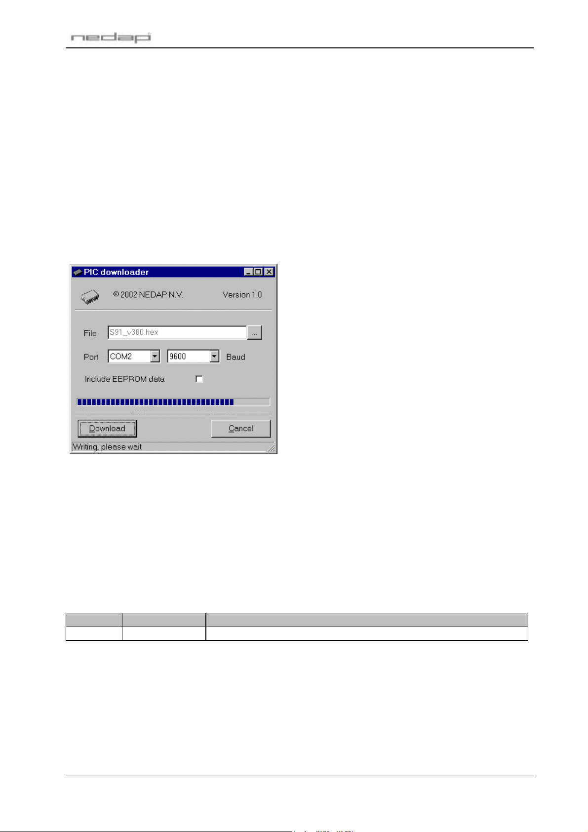
P61 firmware
5 FIRMWARE UPGRADING
The Microchip PIC16F876 is a single chip flash based microcontroller, which allows to upgrade the
firmware by the asynchronous serial interface. The upgrading is performed by a freeware application
called "PIC downloader" which downloads the firmware file (*.hex) to the microcontroller. The upgrade
procedure is described below. Note that the bootloader communicates always at 9600 baud, independent
from the baudrate selected with the DIP-switches.
1. Select the firmware file (*.hex) by clicking the Browse … button.
2. Select the communications port to which the TRANS-IT® is connected.
3. Click the Download button to start downloading the firmware file.
4. The PIC downloader searches for the bootloader.
5. If the TRANS-IT® is properly connected and PIC downloader is setup correctly the firmware is
downloaded. The window should look like shown in Figure 5.
6. Once the downloading has completed the PIC downloader displays the message 'Download
successfully completed' and the TRANS-IT® starts the upgraded firmware.
Figure 5: PIC downloader in progress
Note1: If the message 'Searching for bootloader' does not disappear check the cables and the com-port settings.
Sometimes it may be required to reset the TRANS-IT® before the bootloader can be found.
Note2: Aborted downloads may cause the TRANS-IT® to stop functioning. In such cases repeat the upgrade
procedure until it succeeds.
6 FIRMWARE REVISION HISTORY
Below the P61 firmware modifications are listed. For information on how to obtain the latest release of the
P61 firmware contact Nedap.
Version Date Notes/Bugs fixed
v3.00
Table 3: Revision history
• First release
© Nedap IDEAS, P.O. Box 103, NL-7140 AC GROENLO Page 12 of 18
Page 54
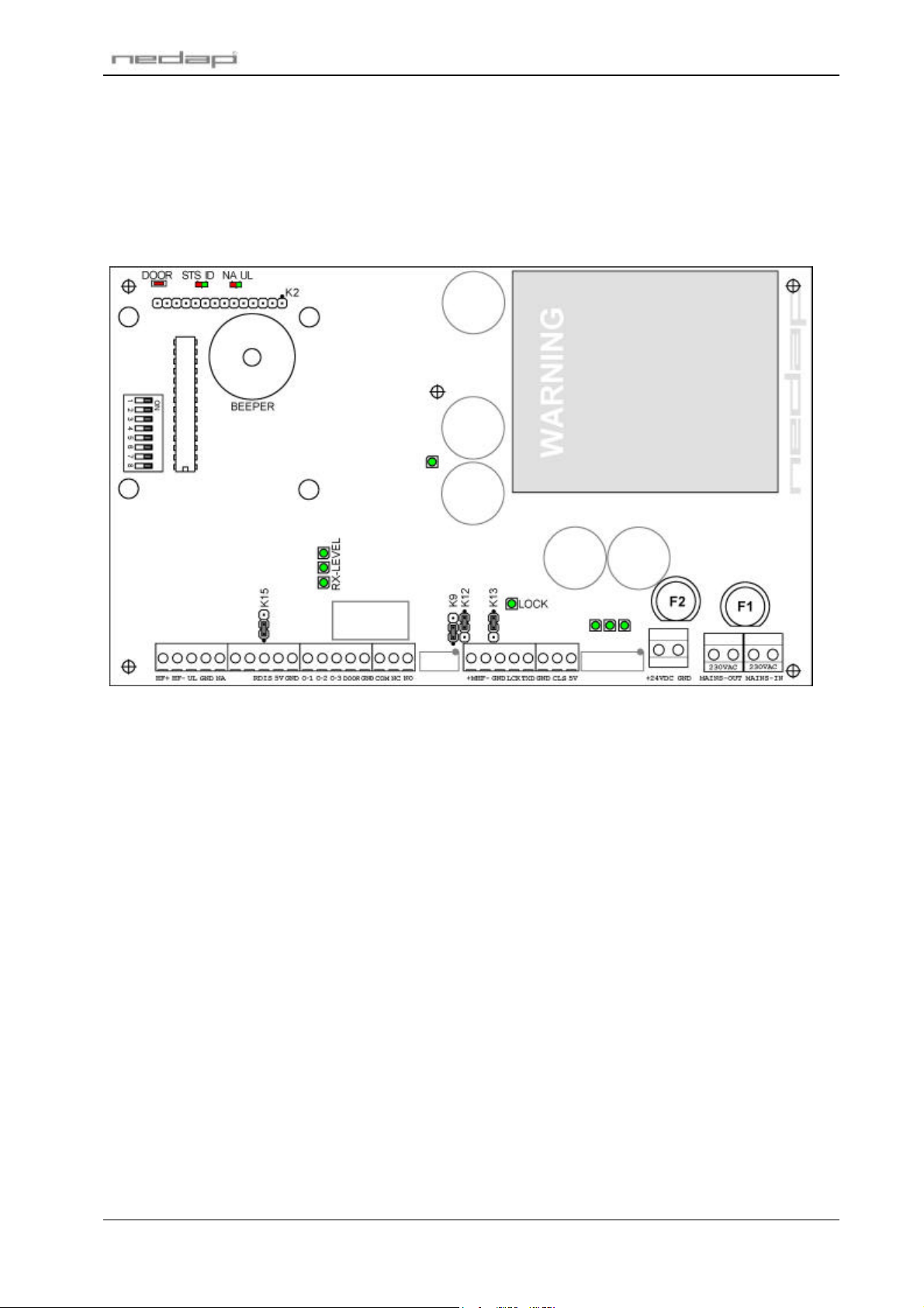
P61 firmware
A HARDWARE
The P61 firmware is developed for the TRANS-IT® (PS-270) microwave reader. Below an overview of the
hardware components is shown. For more details about the connections and electrical specifications refer
to the TRANS-IT® (PS-270) installation guide.
Figure 6: Overview PS-270 board
© Nedap IDEAS, P.O. Box 103, NL-7140 AC GROENLO Page 13 of 18
Page 55
P61 firmware
B ASCII TABLE
Dec Hex Char Dec Hex Char Dec Hex Char Dec Hex Char
0 0 NUL 32 20 SP 64 40 @ 96 60 `
1 1 SOH 33 21 ! 65 41 A 97 61 a
2 2 STX 34 22 " 66 42 B 98 62 b
3 3 ETX 35 23 # 67 43 C 99 63 c
4 4 EOT 36 24 $ 68 44 D 100 64 d
5 5 ENQ 37 25 % 69 45 E 101 65 e
6 6 ACK 38 26 & 70 46 F 102 66 f
7 7 BEL 39 27 ' 71 47 G 103 67 g
8 8 BS 40 28 ( 72 48 H 104 68 h
9 9 HT 41 29 ) 73 49 I 105 69 i
10 A LF 42 2A * 74 4A J 106 6A j
11 B VT 43 2B + 75 4B K 107 6B k
12 C FF 44 2C , 76 4C L 108 6C l
13 D CR 45 2D - 77 4D M 109 6D m
14 E SO 46 2E . 78 4E N 110 6E n
15 F SI 47 2F / 79 4F O 111 6F o
16 10 DLE 48 30 0 80 50 P 112 70 p
17 11 DC1 49 31 1 81 51 Q 113 71 q
18 12 DC2 50 32 2 82 52 R 114 72 r
19 13 DC3 51 33 3 83 53 S 115 73 s
20 14 DC4 52 34 4 84 54 T 116 74 t
21 15 NAK 53 35 5 85 55 U 117 75 u
22 16 SYN 54 36 6 86 56 V 118 76 v
23 17 ETB 55 37 7 87 57 W 119 78 w
24 18 CAN 56 38 8 88 58 X 120 78 x
25 19 EM 57 39 9 89 59 Y 121 79 y
26 1A SUB 58 3A : 90 5A Z 122 7A z
27 1B ESC 59 3B ; 91 5B [ 123 7B {
28 1C FS 60 3C < 92 5C \ 124 7C |
29 1D GS 61 3D = 93 5D ] 125 7D }
30 1E RS 62 3E > 94 5E ^ 126 7E ~
31 1F US 63 3F ? 95 5F _ 127 7F DEL
© Nedap IDEAS, P.O. Box 103, NL-7140 AC GROENLO Page 14 of 18
Page 56
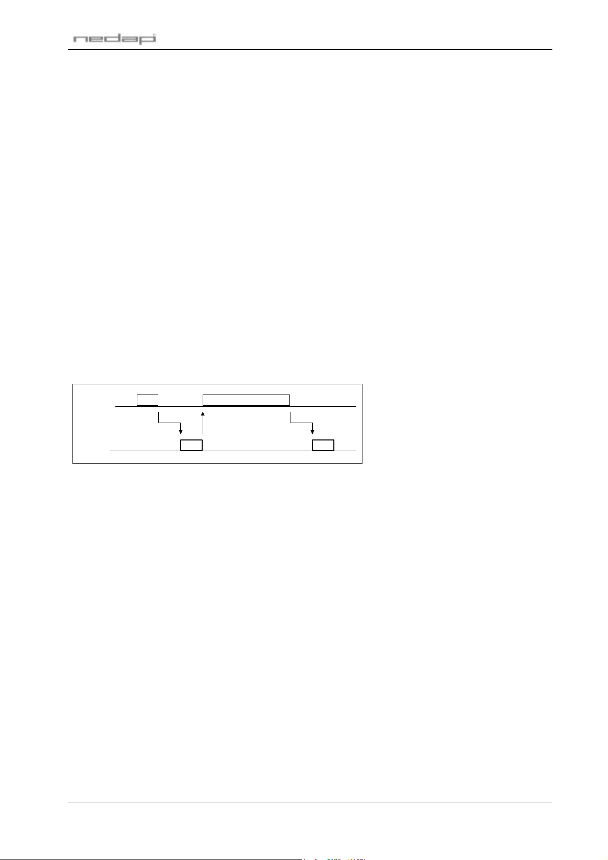
P61 firmware
C DC2/DC4 PROTOCOL
DC2/DC4 protocol is the standard Nedap protocol which supports two-way communications, error checking
and software handshaking.
C.1 DATA FORMAT
Baudrate: 9600(default), 1200, 19200 or 39400. Setup with DIP-switches (see chapter 2).
Databits: 7(default) or 8. Setup with DIP-switches (see chapter 2).
Parity: even(default) or none. Setup with DIP-switches (see chapter 2).
Stopbits: 1
C.2 PROTOCOL DESCRIPTION
The DC2/DC4 protocol is a serial, asynchronous protocol for ASCII communication.
The communications is started by sending a DC2 character and waiting for a DC4 character response.
The DC4 character is the signal that the receiver is ready to accept a message. When there is no DC4
response within 2 seconds the communication is aborted. If the DC4 character is received the transmitter
will send the data message and waits for an ACK or NAK character response. The ACK character is the
confirmation that the message was correctly received. The NAK character is the signal that the receiver
has detected an error in the data message. When there is no ACK response within 4 seconds the
communication is aborted.
Both reader and host can startup the communication by sending a DC2. When the reader and the host
startup the communication at the same time, the host will have the precedence to transmit it's message. The
reader will (temporarily) withdraw. In other words the reader (and not the host) transmits a DC4 character.
Transmit
Receive
DC2
< 2 sec < 4 sec
DC4
data message
ACK
Figure 7: Timing diagram DC2/DC4 protocol
When an event message (initiated by Nedap) is not acknowledged the event is NOT be cleared from the
event buffer. Nedap resends the event message later.
When a reply message is not acknowledged the reply is lost. The host has to resent the request in order to
get the reply again.
C.3 SPECIAL CHARACTERS
The DC2/DC4 protocol supports 7 bit ASCII data communication. See also appendix B ASCII table.
The ASCII control characters are reserved for message handling. The remaining characters (in the range
from 20 hex to 7F hex) are valid characters for the data.
The used special characters are:
DC2 12 hex Are you ready to receive?
DC4 14 hex I'm ready to receive!
STX 02 hex Here comes the message.
ETX 03 hex This was the message.
ACK 06 hex I understood the message.
NAK 15 hex I didn't understand the message.
© Nedap IDEAS, P.O. Box 103, NL-7140 AC GROENLO Page 15 of 18
Page 57

P61 firmware
C.4 DATA MESSAGE
The data message is built up as follows:
STX <ADDR> FF [ff] [data] <cc> ETX
Where: STX STX character.
<ADDR> Address. For P61 firmware always '010101'.
FF Two character command number. See chapter 4.1.2.
[ff] Optional two character sub command number. See chapter 4.1.2.
[data] Optional data.
<cc> Two bytes checksum.
ETX ETX character.
C.5 CHECKSUM CALCULATION
The checksum is calculated following the procedure below:
1. Sum all character values in the message. STX, ETX and the checksum itself not included.
2. This sum must be shortened into 1 byte.
3. Split this byte up into two bytes.
4. Finally add the value of character '0' to both bytes to make sure the checksum does not contain control
characters.
Example:
message = '0101010293'
ASCII characters are enclosed within quotes, all other values are in hexadecimal notation:
1. Sum all character values: 4 x '0' + 3 x '1' + '2' + '9' + '3' = 4 x 30 + 3 x 31 + 32 + 39 + 33 = 1F1.
2. Shorten sum into 1 byte: F1.
3. Split byte into 2 bytes: 0F and 01.
4. Add '0' to both bytes: 0F + '0' = 0F + 30 = 3F = '?' and 01 + '0' = 01 + 30 = 31 = '1'.
Complete message = STX'0101010293?1'ETX
© Nedap IDEAS, P.O. Box 103, NL-7140 AC GROENLO Page 16 of 18
Page 58
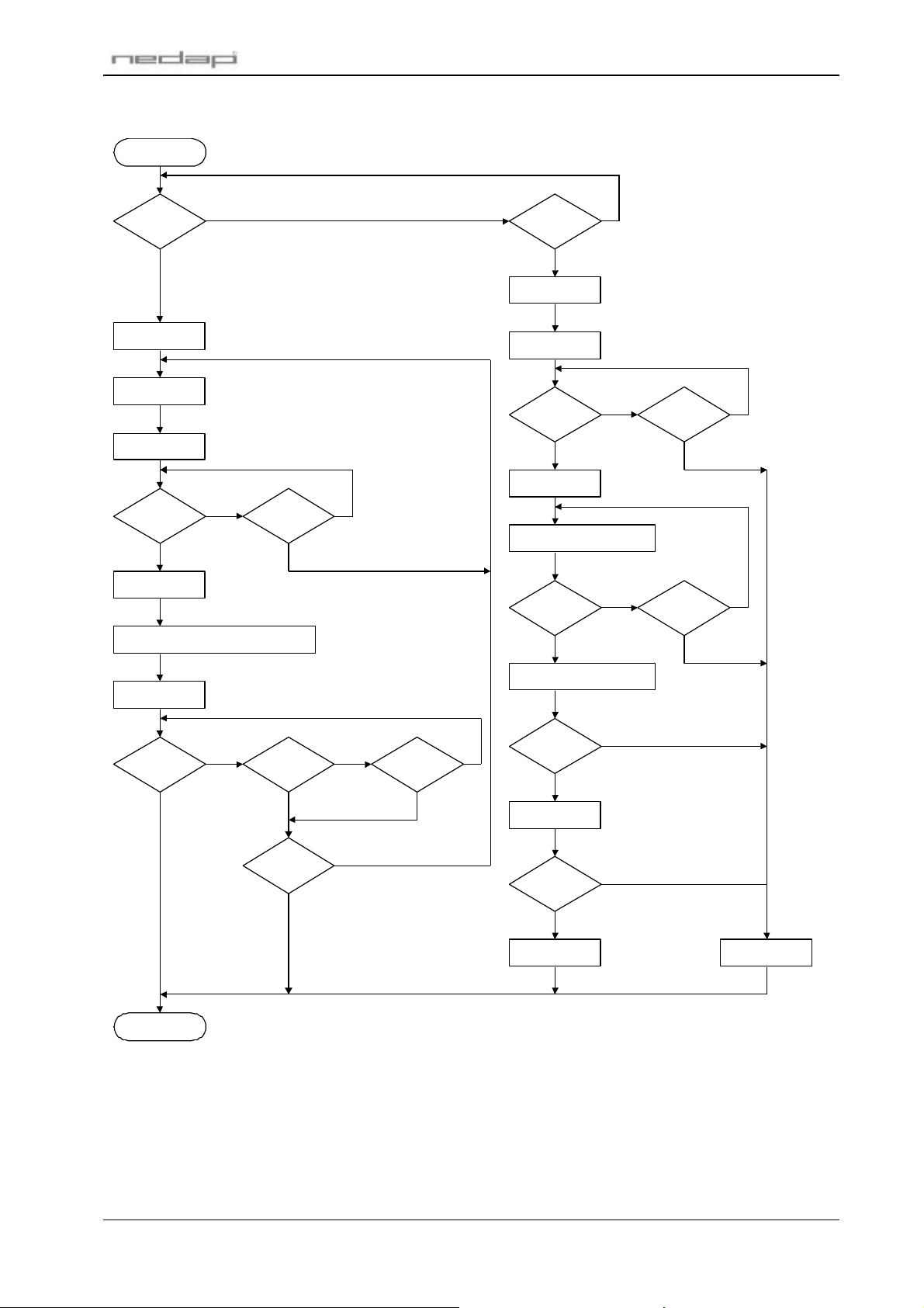
C.6 FLOWCHART
4 sec.
> 3
2 sec.
NONONO
NO
NO
YES
4 sec.
YES
NO
2 sec.
NO
YES
BEGIN
P61 firmware
Send Msg
YES
CommTries = 0
à
DC2
Timeout=0
DC4
YES
Timeout
NO NO
ß
CommTries++
STX <message> <checksum> ETX
YES
à
ß
DC2
YES
à
DC4
Timeout=0
NO
ß
STX
Timeout=0
Receive and store byte
ß
ETX
YES
Timeout
NO
ß
Timeout
YES
Timeout=0
ß
ACK
YES YESYES
Goto BEGIN
ß
NAK
CommTries
YES
Calculate checksum
NO
YES
Timeout
Checksum
OK ?
Handle message
NO
Message
succesfull
ACK
NO
à
NAK
à
Transmit
ß
Receive
à
© Nedap IDEAS, P.O. Box 103, NL-7140 AC GROENLO Page 17 of 18
Page 59

P61 firmware
D DECIMAL TO ASCII CONVERSION TABLE
dec ascii dec ascii dec ascii dec ascii dec ascii dec ascii dec ascii dec ascii
0 0 0 32 2 0 64 4 0 96 6 0 128 8 0 160 : 0 192 < 0 224 > 0
1 0 1 33 2 1 65 4 1 97 6 1 129 8 1 161 : 1 193 < 1 225 > 1
2 0 2 34 2 2 66 4 2 98 6 2 130 8 2 162 : 2 194 < 2 226 > 2
3 0 3 35 2 3 67 4 3 99 6 3 131 8 3 163 : 3 195 < 3 227 > 3
4 0 4 36 2 4 68 4 4 100 6 4 132 8 4 164 : 4 196 < 4 228 > 4
5 0 5 37 2 5 69 4 5 101 6 5 133 8 5 165 : 5 197 < 5 229 > 5
6 0 6 38 2 6 70 4 6 102 6 6 134 8 6 166 : 6 198 < 6 230 > 6
7 0 7 39 2 7 71 4 7 103 6 7 135 8 7 167 : 7 199 < 7 231 > 7
8 0 8 40 2 8 72 4 8 104 6 8 136 8 8 168 : 8 200 < 8 232 > 8
9 0 9 41 2 9 73 4 9 105 6 9 137 8 9 169 : 9 201 < 9 233 > 9
10 0 : 42 2 : 74 4 : 106 6 : 138 8 : 170 : : 202 < : 234 > :
11 0 ; 43 2 ; 75 4 ; 107 6 ; 139 8 ; 171 : ; 203 < ; 235 > ;
12 0 < 44 2 < 76 4 < 108 6 < 140 8 < 172 : < 204 < < 236 > <
13 0 = 45 2 = 77 4 = 109 6 = 141 8 = 173 : = 205 < = 237 > =
14 0 > 46 2 > 78 4 > 110 6 > 142 8 > 174 : > 206 < > 238 > >
15 0 ? 47 2 ? 79 4 ? 111 6 ? 143 8 ? 175 : ? 207 < ? 239 > ?
16 1 0 48 3 0 80 5 0 112 7 0 144 9 0 176 ; 0 208 = 0 240 ? 0
17 1 1 49 3 1 81 5 1 113 7 1 145 9 1 177 ; 1 209 = 1 241 ? 1
18 1 2 50 3 2 82 5 2 114 7 2 146 9 2 178 ; 2 210 = 2 242 ? 2
19 1 3 51 3 3 83 5 3 115 7 3 147 9 3 179 ; 3 211 = 3 243 ? 3
20 1 4 52 3 4 84 5 4 116 7 4 148 9 4 180 ; 4 212 = 4 244 ? 4
21 1 5 53 3 5 85 5 5 117 7 5 149 9 5 181 ; 5 213 = 5 245 ? 5
22 1 6 54 3 6 86 5 6 118 7 6 150 9 6 182 ; 6 214 = 6 246 ? 6
23 1 7 55 3 7 87 5 7 119 7 7 151 9 7 183 ; 7 215 = 7 247 ? 7
24 1 8 56 3 8 88 5 8 120 7 8 152 9 8 184 ; 8 216 = 8 248 ? 8
25 1 9 57 3 9 89 5 9 121 7 9 153 9 9 185 ; 9 217 = 9 249 ? 9
26 1 : 58 3 : 90 5 : 122 7 : 154 9 : 186 ; : 218 = : 250 ? :
27 1 ; 59 3 ; 91 5 ; 123 7 ; 155 9 ; 187 ; ; 219 = ; 251 ? ;
28 1 < 60 3 < 92 5 < 124 7 < 156 9 < 188 ; < 220 = < 252 ? <
29 1 = 61 3 = 93 5 = 125 7 = 157 9 = 189 ; = 221 = = 253 ? =
30 1 > 62 3 > 94 5 > 126 7 > 158 9 > 190 ; > 222 = > 254 ? >
31 1 ? 63 3 ? 95 5 ? 127 7 ? 159 9 ? 191 ; ? 223 = ? 255 ? ?
© Nedap IDEAS, P.O. Box 103, NL-7140 AC GROENLO Page 18 of 18
 Loading...