


VP1801B
1
EN
Doc. part. no. 5278724 / Manual version 1.1 / 07-2017
Quick start manual
VP1801 Reader Motor Control
THIS SHEET IS ONLY INTENDED AS QUICK START. SEE SERVICE MANUAL FOR DETAILED INSTRUCTIONS
The VP1801 is a Velos component that is used to identify animals for feeding, weighing, milking, heat
detection etc. The VP1801 is equipped with an internal switch to support a double Ethernet connection
(web interface ready) and the existing VC3 interface. The Ethernet channel is used for the main
functionality and communication like software updates and service. An extra communication channel is
available for the VC3 systems. The function is the same as the existing Single Feeder.
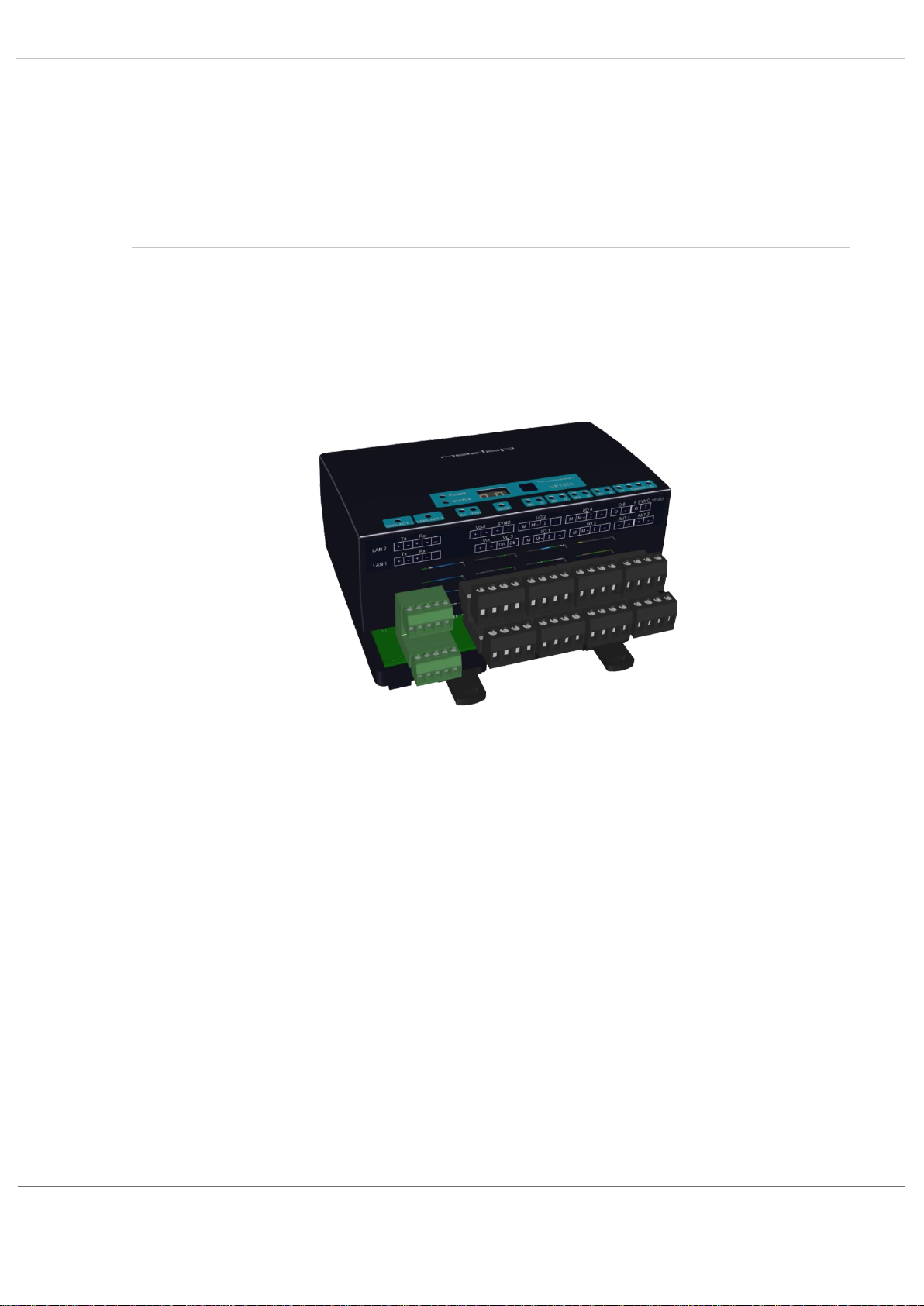
The VP1801 can be installed in a V-box.
2
EN
Doc. part. no. 5278724 / Manual version 1.1 / 07-2017
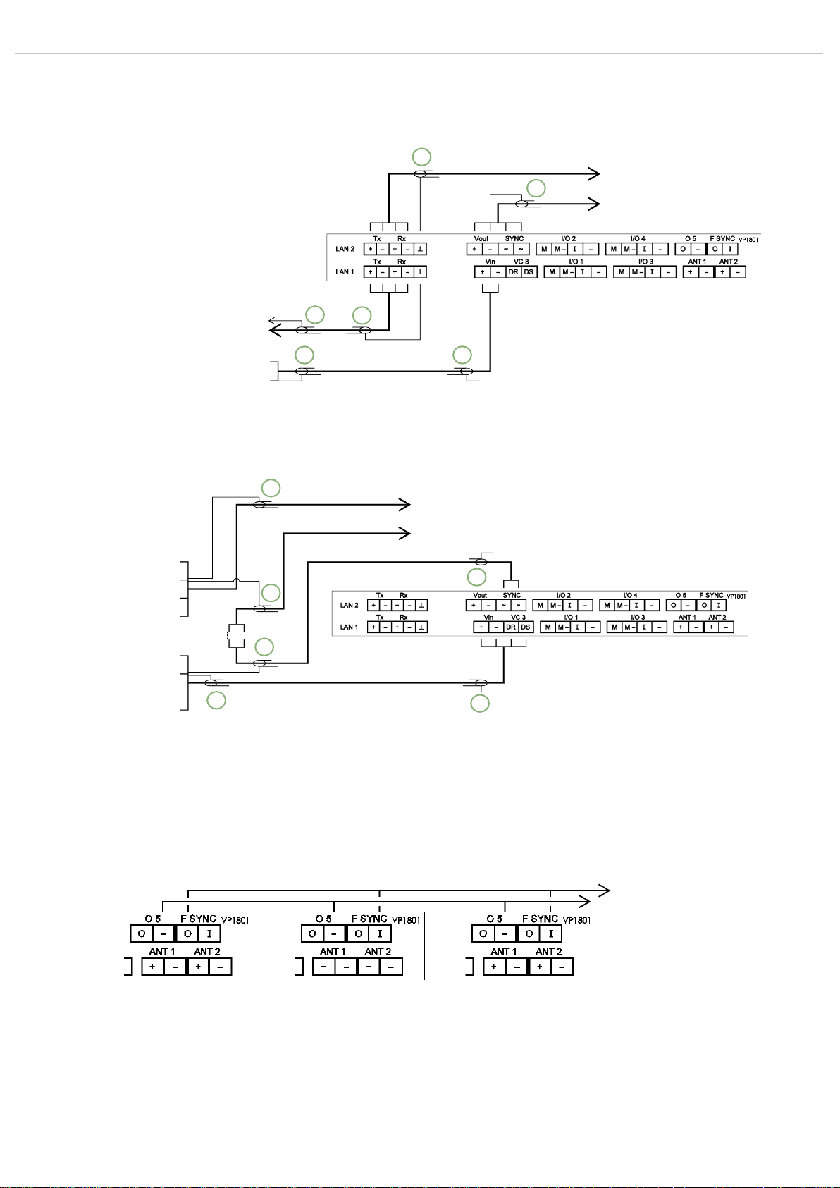
A VP1801 can be connected in different ways:
• To a shielded Ethernet cable and controlled by a switch or VPU:
When connecting the Ethernet cable, the VP1801 automatically detects TX/RX , plus and minus
connections, and switches to the correct connection.
• To a shielded four wire cable and controlled by a VC3 host:
The SYNC connection is necessary for HDX ISO synchronization between other readers. For FDX a
SYNC connection is possible, but not necessary if only one antenna is used. When two antennas are
used the SYNC connection is always needed, even when FDX-only (no ISO) mode is enabled. The
switching between the two antennas uses the ISO timing.
The F SYNC connection is necessary when the distance between two antennas is ≤ 3 m. Connect the F
SYNC as shown in the picture below.
+
-
1. Shielded cable
2. Shielded cable,
shield not connected
to VP1801.
LAN next VP1801
Power
supply
Vin next VP1801
Switch
VPU
VC3 next VP1801
+
-
D
DS
+
-
D
DS
VC3
interface
bridge
SYNC next VP1801
1. Shielded cable
2. Shielded cable,
shield not connected
to VP1801.
F SYNC I next
O5 minus next VP1801
1
1
1
1
1
1
1
1
1
2
2
2

3
EN
Doc. part. no. 5278724 / Manual version 1.1 / 07-2017
Installation steps Ethernet
Step 1 Install the VP1801 in the V-box (or other box). See the manual of the relevant equipment (feeding
station, separation unit etc.) where is indicated how to install the V-box.
Step 2 Connect all required wiring. See the manual of the relevant equipment and the manual of the
required behaviour component.
Step 3 Power up and check the LED indicators, see also the overview on page 9.
Step 4 When the system is equipped with the auto-addressing function, the host computer requires the
address. Select “Sp > y” in the display menu of the VP1801, see page 6. Go to Step 8.
Step 5 When auto-addressing is not available, set the required address manually via “Ad” in the display
menu, see page 6.
Step 6 Check the ip settings via “IP” in the display menu, see page 6. Default DHCP is on. When DHCP
must be switched off, set the required ip address settings via “IP” in the display menu. When DHCP
is switched off, the default IP address is 192.168.1.100.
Step 7 Check the antenna tuning. Select “HF > H1 > tu” in the display menu to start and enable autotune,
see page 7. If external manual adjustment is used (e.g. adjustable antenna-trafo), select “AA” in the
display menu, see page 7.
Step 8 Test the functioning. See manual of the behaviour component. In case of malfunctioning of the
connected devices like sensors, motors, execute a test with options from menu option “It”, see page
7.
Installation steps VC3
Step 1 Install the VP1801 in the V-box (or other box). See the manual of the relevant equipment (feeder,
separation unit etc.) where is indicated how to install the V-box.
Step 2 Connect all required wiring. See the manual of the relevant VC3 application.
Step 3 Power up and check the LED indicators, see also overview on page 9.
Step 4 Set the required VC4 address via “CO > SA” in the display menu, see page 8.
Step 5 Select the VC3 application and other relevant VC3 settings via “CO > AP”, see page 8.
Step 6 Check the antenna tuning. Select “HF > H1 > tu” in the display menu to start and enable autotune,
see page 7. If external manual adjustment is used (e.g. adjustable antenna-trafo), select “AA” in the
display menu, see page 7.
Step 7 Test the functioning. See the manual of the VC3 application. In case of malfunctioning of the
connected devices like sensors or valves, execute a test with options from menu option “It”, see
page 7.

4
EN
Doc. part. no. 5278724 / Manual version 1.1 / 07-2017
Connections
See the manual of the concerning behaviour component for a detailed overview of the connections. O5 is default
controlled by the identification process of the VP1801 itself, and can be overruled by the behaviour component. If the
V-box has a signal light, connect it default to O5.
When connecting the Ethernet cable, the VP1801 automatically detects TX/RX , plus and minus connections, and
switches to the correct connection.
Details VP1801 inputs and outputs
LAN
Tx +
Transmit (shielded CAT5E FTP (Foiled Twister Pair, also called S/UTP) stranded
AWG26 or AWG24 (preferred)). Cable length max. 100 m.
Tx -
Transmit
Rx +
Receive
Rx -
Receive
Ethernet shielding
Vin
+
Input voltage 25 VDC, +20% -20%
-
Minus
Vout
+
Output (max 4A)
-
Minus
VC3
DR
VC3 data receive. Shielded cable, cable length max. 40 m.
DS
VC3 data send
SYNC
~
Synchronisation for HDX or 2 installed antennas, AC (no plus or minus, cable must
be shielded twisted pair). Max. 20 devices parallel, total cable length max. 300 m.
~
See above
I/O 1 .. 4
M
Motor output or normal output max 3.5A as total current for the 4 outputs. Cable
length max. 3 m.
M-
Minus for motor output or normal output
I
Input of motor or normal input
-
Minus for motor input or normal input
O5
O
Output max 400mA continue. Cable length max. 3 m.
-
Minus for output (O) and minus input (I)
ANT 1
+
Antenna 1 (core of coax). Cable length max. 10 m.
-
Minus for antenna 1 (shield of coax)
ANT 2
+
Antenna 2 (core of coax). Cable length max. 10 m.
-
Minus for antenna 2 (shield of coax)
F SYNC
O
Output for FDX synchronization of the antenna signal phase (core of coax: shield
connected with minus of O5). Cable length max. 3 m.
I
Input for synchronization of antenna signal phase (core of coax: shield connected
with minus of O5). Cable length max. 3 m.
Antennas
The VP1801 has two antenna connections and one internal reader. When two antennas are connected, the used
application determines if the second antenna is used or not. In case the reader has to control both antennas, the
reader switches fast between the two antennas in a smart way. That means the identification time is divided over the
two antennas with a switching time that can vary between 24ms and 120ms in case both antennas have the same
priority. Priority is controlled by Ethernet control like a behaviour component.
Autotune
The VP1801 is equipped with the autotune function. This means it can tune an antenna by itself due to an integrated
internal tuning-circuit on board. Tuning can be started with the display menu “HF > H1 > tu”, remote from an external
command over Ethernet or with the web-interface of the VP1801.
Important!
Autotune works with all Nedap antennas. In case external antenna adjustment is used (e.g. adjustable
antenna-trafo), the autotune function must be switched off to achieve the maximum reading distance.
This can be done via “HF > HI > AA” in the menu display of the VP1801, see page 6. Then the autotune
function is disabled until it is started again with the display menu “HF > H1 > tu”.
 Loading...