

Necta Sfera 6-36 R/F, Sfera 6-36 R/I, Sfera 6-40 R/F, Sfera 6-40 R/I LX, Sfera 6-36R / B Service Manual
...
NECTA SPA TECHNICAL MANUAL “SFERA “
Manual “ SFERA” 1 / 19
SERVICE MANUAL
“ SFERA ”
BASIC TECHNICAL MANUAL
THE CONTENTS OF THIS DOCUMENT ARE INTENDED FOR NECTA’S AFTER SALES PERSONNEL.
A
FTER SALES SERVICE Snack & Food
NECTA SPA TECHNICAL MANUAL “SFERA “
Manual “ SFERA” 2 / 19
NOTE
The above systems and functional units are specific to this machine.
All functional units installed but not listed in this document, are also used in other machines in the same range;
therefore they will be described in a separate manual for machines belonging to the same range, where all base
functional units will be described more in detail.
Sfera:
View of user interface
TABLE OF CONTENTS
1
2
3
4
5
6
7
8
9
Layout - Models
Electrical systems, connections and configuration
Vending systems
Power supply and Wiring
Cooling unit
Cabinet and Door
Trouble-shooting
HACCP directive (Use instructions)
Periodical cleaning and hygiene
( Daily – Weekly – Yearly )
Pages 3-4-5
Pages 6-7-8-9-10
Page 10
Page 12
Page 13
Page 14
Pages 15 -16
Page 17
Pages 18 -19
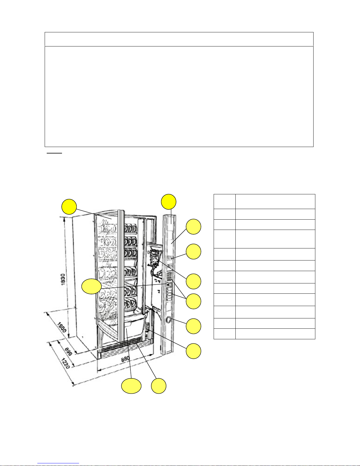
Ref.
DESCRIPTION
1
Rounded glass door
2
Advertising spaces
3
Compartment pre-set for key-type
payment systems or other
systems
4
Machine status information
display
5
CPU board
6
Double keypad with direct and
numeric selection
7
Coin return compartment
8
Power supply unit / fuses / door
safety switch
9
Removable grille for cleaning the
condenser’s filter
10
Product dispensing compartment
11
Key lock
1
2
8
4
1
2
7
6
5
3
8
4
9
10
11
NECTA SPA TECHNICAL MANUAL “SFERA “
Manual “ SFERA” 3 / 19
1 – LAYOUT - MODELS
Example of Sfera model’s codification
Layout Italy - Version
6-40R / I LX
Meaning:
SFERA
with 6 trays for a total of 40 selections
Refrigerated version R
(a non refrigerated version is also available)
Country: Italy I
Approved by IMQ Q
NB 1: (if the letter Q is not present it means that such version is not approved by IMQ, or that it is awaiting
approval
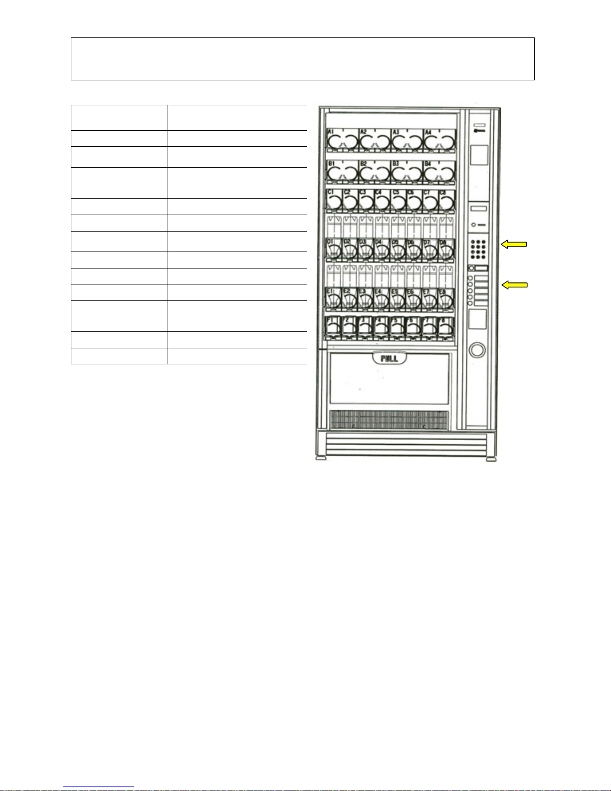
Version
LX - Model with double keypad (Numeric and direct for five advertised selections)
NB2: without such code, the machine is supplied with only the 12-button numeric keypad
DESCRIPTION
VARIABLES
TRAYS Up to 6 max
HEIGHT 0F TRAYS 96 mm min and up to 219 mm
max
PARTITIONS PER
TRAY
2 triple + 1 double (or 2 singles)
4 doubles
8 singles
PRICES PER TRAY One for each selection
TIME BANDS Available for configuration
PAYMENT SYSTEMS Serial – EXE- as standard feature
MDB – BDV – with additional board
VEND SYSTEMS With single and double spiral
DIMENSIONS H 1830 x L880 x D 890
WEIGHT -----
OVERALL
DIMENSION
(with door open)
H 1830 x L 880 x D1 1500
LAMP 1 x 36 W (Flourescent/Neon)
ABSORBED POWER 510 W
Numeric
5-selection
NECTA SPA TECHNICAL MANUAL “SFERA “
Manual “ SFERA” 4 / 19
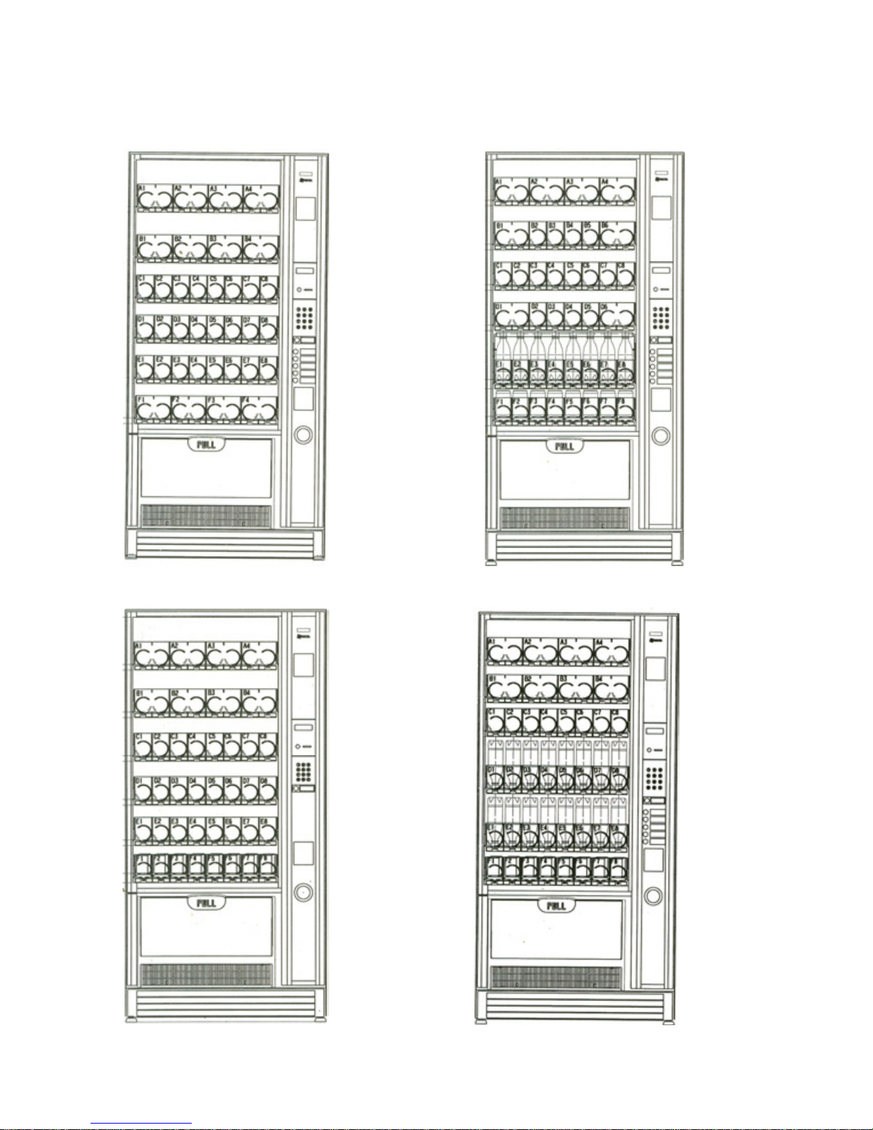
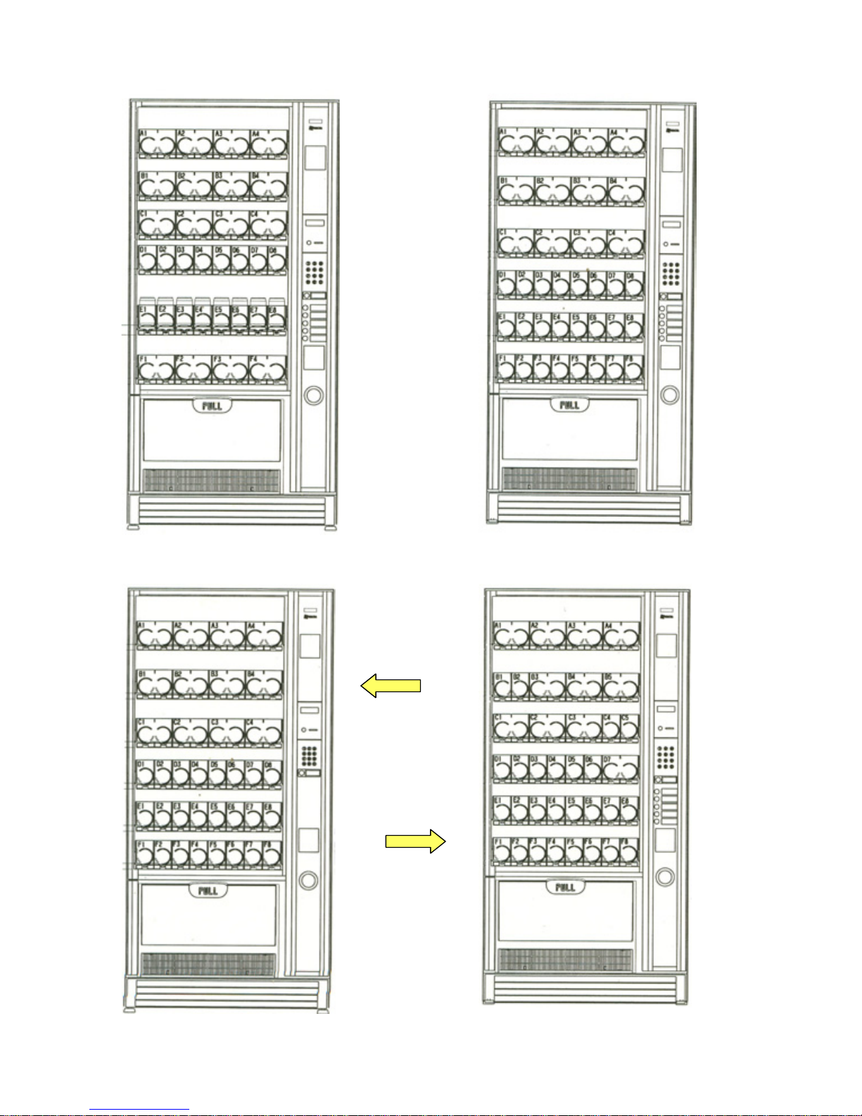
Examples of different tray configurations and positions.
The examples correspond to real layouts (the code is indicated on the side); in any case there are many
configurations options with simple and quick change operations.
Release spirals with different pitches are provided, as indicated in the user manual
Sfera 6 –40 R/F
Sfera 6 – 36 R/F
Sfera 6 – 36 R/I
V
ersions provided
for the French
market
Sfera 6 –40 R/I LX
V
ersions provided
for the Italian
market
NECTA SPA TECHNICAL MANUAL “SFERA “
Manual “ SFERA” 5 / 19
Sfera 6 – 36R / B
Sfera 6 –36R/UK Sfera 6 – 32R / E
Sfera 6 –36R / D
V
ersion provided
for Spain
V
ersion provided
for Belgium
V
ersion provided
for Germany
NECTA SPA TECHNICAL MANUAL “SFERA “
Manual “ SFERA” 6 / 19
2 - ELECTRICAL SYSTEMS - CONNECTIONS - CONFIGURATIONS
The machine is designed to operate under a single-phase voltage of 230 V AC (+5-10V)
It is protected with two T 6,3 A fuses on both phases.
A safety transformer supplies power to very-low voltage components (24 V DC), while the cooling unit and
the Flourescent lamp are powered with the mains voltage.
With regard to the safety transformer:
The primary winding is protected with a T 800 mA fuse
The secondary winding 25 V is protected with the following fuses:: T 1 A – T 4 A
The slide-out compartment door is fitted with a bipolar safety switch.
The switch is located on the front panel of the power supply unit, and when opening the compartment it
disconnects the power from all parts that can be accessed for normal maintenance and cleaning operations.
The only parts that stay energised are those protected by suitable covers carrying a plate with the warning
"Disconnect power before removing the cover”; to clear the voltage the power the power supply cable
must be disconnected from power outlet
or in the case of connection to a dedicated power board, it should
be set to OFF
The power cable can be supplied as standard feature and chosen
among the following types:
HO5 RN – F copper with a 3 x 1.5 mm
2
section
1) HO5 VV – F ,, ,, ,, ,,
2) HO7 RN – F ,, ,, ,, ,,
In all configurations the cable is fitted with a SCHUKO plug
permanently fixed to the cable
NOTE :
In the event of replacement cables of exactly the same
characteristics must be used.
Since the “SFERA” vending machine is approved by an
electrical safety certification institute (IMQ), replacements
with non-original components are not permitted.
Otherwise the electrical safety certificate and the warranty will
be void.
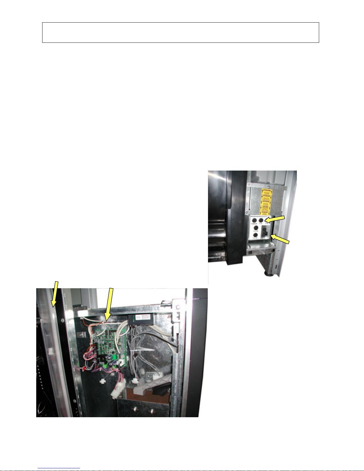
ACTUATION BOARD AND CONNECTIONS
(Electrical compartment open)
A
flourescente lamp is located vertically on the righthand side inside the cabinet; the starter is fitted
inside the lamp holder. (see page 12)
The ballast is located inside the power supply
compartment.
The CPU board controls also the 24 V actuations by
means of TRIACs and Darlington switches, while the
lamp and the cooling unit are controlled by a relay
card located inside the power supply compartment.
(see page 12)
Some versions are provided with monitoring of the
selected product fall into the dispensing
compartment by means of a card with
receiver/transmitter diodes (infrared).
If during a selection the barrier is not interrupted it
means that a product is finished or jammed, in this
case the system will further attempt releasing the
product with small rotations; if also this fails the
selection is disabled and the customer is entitled to a
new selection.
CPU board and connections
Fluorescent lamp compartment
Protection
fuses
bipolar safety
switch
 Loading...