

Page 1
INSTALLATION, USE AND MAINTENANCE MANUAL
Colibrì Espresso
MDB Protocol
UK English
DOC. NO. H 217U 00
EDITION 1 03-2003
Page 2

Page 3
DICHIARAZIONE DI CONFORMITA’
DECLARATION OF CONFORMITY
DÉCLARATION DE CONFORMITÉ
KONFORMITÄTSERKLÄRUNG
DECLARACIÓN DE CONFORMIDAD
DECLARAÇÃO DE CONFORMIDADE
VERKLARING VAN OVEREENSTEMMING
INTYG OM ÖVERENSSTÄMMELSE
OVERENSSTEMMELSESERKLÆRING
YHDENMUKAISUUSTODISTUS
Valbrembo, 03/05/2001
Dichiara che la macchina descritta nella targhetta di identificazione, è conforme alle disposizioni legislative delle direttive:
89/392, 89/336, 73/23 CEE e successive modifiche ed integrazioni.
Declares that the machine described in the identification plate conforms to the legislative directions of the directives: 89/
392, 89/336, 73/23 EEC and further amendments and integrations.
Déclare que l’appareil décrit dans la plaque signalétique satisfait aux prescriptions des directives: 89/392, 89/336, 73/
23 CEE et modifications/intégrations suivantes.
Erklärt, daß das im Typenschild beschriebene Gerät den EWG Richtlinien 89/392,
89/336, 73/23 sowie den folgenden Änderungen/Ergänzungen entspricht.
Declara que la máquina descripta en la placa de identificación, resulta conforme a las disposiciones legislativas de las
directivas: 89/392 , 89/336, 73/23 CEE y modificaciones y integraciones sucesivas.
Declara que o distribuidor descrita na chapa de identificação é conforme às disposições legislativas das directivas CEE
89/392, 89/336 e 73/23 e sucessivas modificações e integrações.
Verklaart dat de op de identificatieplaat beschreven machine overeenstemt met de bepalingen van de EEG richtlijnen
89/392, 89/336 en 73/23 en de daaropvolgende wijzigingen en aanvullingen.
Intygar att maskinen som beskrivs på identifieringsskylten överensstämmer med lagstiftningsföreskrifterna i direktiven:
89/392, 89/336, 73/23 CEE och påföljande och kompletteringar.
Det erklæres herved, at automaten angivet på typeskiltet er i overensstemmelse med direktiverne
89/392, 89/336 og 73/23 EU og de senere ændringer og tillæg.
Forsikrer under eget ansvar at apparatet som beskrives i identifikasjonsplaten, er i overensstemmelse med vilkårene i
EU-direktivene 89/392, 89/336, 73/23 med endringer.
Vahvistaa, että arvokyltissä kuvattu laite vastaa EU-direktiivien 89/392, 89/336, 73/23 sekä niihin myöhemmin tehtyjen
muutosten määräyksiä.
ANTONIO CAVO
C.E.O
Page 4
Page 5

TABLE OF CONTENTS
INTRODUCTION PAGE 2
IDENTIFICATION OF THE VENDING MACHINE PAGE 2
IN CASE OF FAILURE PAGE 2
TRANSPORT AND STORAGE PAGE 2
POSITIONING THE VENDING MACHINE PAGE 3
WARNING FOR INSTALLATION PAGE 3
PRECAUTIONS IN USING THE MACHINE PAGE 3
WARNING FOR SCRAPPING PAGE 3
TECHNICAL SPECIFICATIONS PAGE 3
POWER CONSUMPTION PAGE 4
ACCESSORIES PAGE 4
LOADING AND CLEANING PAGE 5
DOOR SWITCH PAGE 5
MAINTENANCE AND DISINFECTION PAGE 5
USING THE VENDING MACHINE PAGE 5
CONTROLS AND INFORMATION PAGE 5
NOISE LEVEL PAGE 5
LOADING CUPS PAGE 6
LOADING COFFEE PAGE 6
LOADING SUGAR AND INSTANT PRODUCTS PAGE 6
LOADING STIRRERS PAGE 6
SANITISING THE MIXERS AND
FOODSTUFF CIRCUITS PAGE 7
CLEANING THE MIXER PAGE 7
CLEANING THE WATER SUPPLY TANK PAGE 8
CLEANING THE SUGAR DISPENSER PAGE 8
CLEANING THE WASTE TRAYS PAGE 8
CLEANING THE CUP SHIFT ARM PAGE 8
WEEKLY CLEANING OF COFFEE UNIT PAGE 8
SUSPENDING FROM USE PAGE 8
INSTALLATION PAGE 9
UNPACKING THE VENDING MACHINE PAGE 9
MACHINE AND CABINET ASSEMBLY PAGE 9
INSTALLING THE PAYMENT SYSTEM PAGE 10
CONNECTING TO THE POWER SUPPLY PAGE 10
DIFFERENTIAL SWITCH PAGE 10
DOOR SWITCH PAGE 11
WATER SOFTENER UNIT PAGE 11
INSERTING THE LABELS PAGE 11
LENGTH OF THE STIRRERS PAGE 11
FILLING THE WATER SYSTEM PAGE 11
INITIALISING PAGE 11
COFFEE UNIT OPERATION PAGE 12
COFFEE DISPENSING CYCLE PAGE 12
CHECKING AND ADJUSTING
THE MACHINE SETTINGS PAGE 13
STANDARD SETTINGS PAGE 13
ADJUSTING THE BREWING CHAMBER VOLUME PAGE 13
WATER TEMPERATURE CONTROL PAGE 13
ADJUSTING THE GRADE OF GRINDING PAGE 14
ADJUSTING THE COFFEE DOSE PAGE 14
OPERATING MODES PAGE 14
NORMAL OPERATING MODE PAGE 14
PRE-SELECTIONS PAGE 15
MAINTENANCE MODE PAGE 15
AUTOTEST PAGE 16
EMPTYING THE AIR-BREAK PAGE 16
DISPLAYING THE STATISTICS PAGE 16
PRINTING THE STATISTICS PAGE 16
RESETTING THE FAILURE STATISTICS PAGE 17
GENERAL COUNTER PAGE 17
CHANGE TUBES CONTROL PAGE 17
PROGRAMMING PAGE 17
DISPLAYING THE EXISTING FAILURES PAGE 18
PROGRAMMING THE WATER
AND POWDER DOSES PAGE 19
PROGRAMMING THE PRICES PAGE 19
PROGRAMMING THE PRICES
AND THE PUSH-BUTTON STATUS PAGE 19
PROGRAMMING THE BASIC COIN
AND THE DECIMAL POINT PAGE 19
PAYMENT SYSTEMS PAGE 19
PROGRAMMING THE VALIDATOR PAGE 19
PROGRAMMING THE MDB DATA PAGE 20
INITIALISING PAGE 20
SETTING THE MACHINE CODE PAGE 20
MACHINE CONFIGURATION PAGE 21
OPERATION COUNTER PAGE 21
SETTING THE PROMOTIONAL MESSAGE PAGE 21
LANGUAGE SELECTION PAGE 21
WHIPPING TIME PAGE 22
PROGRAMMING ACCESS PASSWORD PAGE 22
CONFIGURING THE SELECTION PAGE 22
DISCOUNT DATA PAGE 22
SPECIAL SALES PAGE 22
DIRECT FUNCTIONS PAGE 22
INSTALLATION PAGE 22
RESETTING FAILURES PAGE 22
MAINTENANCE PAGE 23
INTRODUCTION PAGE 23
BREWING UNIT MAINTENANCE PAGE 23
ANNUAL SANITISING PAGE 24
PRINTED BOARD FUNCTIONS
AND INDICATOR LIGHTS PAGE 24
CONTROL BOARD PAGE 24
PAYMENT SYSTEMS EXPANSION BOARD PAGE 25
PUSH-BUTTON BOARD PAGE 25
HYDRAULIC SYSTEM PAGE 26
MAINTENANCE MENU PAGE 29
PROGRAMMING MENU PAGE 31
WIRING DIAGRAMS PAGE 39
© by NECTA VENDING SOLUTIONS SpA 03-2003 217 00
1
Page 6
INTRODUCTION
IDENTIFICATION OF THE VENDING
MACHINE AND ITS CHARACTERISTICS
This technical documentation is part and parcel of the
vending machine and must always follow the machine
in case it is moved or transfer of ownership, so as to
allow consultation by different operators.
Before starting installation and using the machine, it is first
necessary to carefully read and understand the instructions contained in this manual, as they offer important
information on installation safety, operating instructions
and maintenance.
This manual is divided into three chapters.
The first chapter describes the loading and routine maintenance operations which are carried out in areas of the
machine accessible with simple use of the door key,
without using any other tools.
The second chapter contains the instructions for correct
installation and all information necessary for optimum use
of the machine.
The third chapter describes maintenance operations
which involve the use of tools to access potentially dangerous areas.
The operations described in the second and third
chapters must be carried out only by personnel who
have the specific knowledge of the machine functioning from a point of view of electrical safety and health
regulations.
The vending machines in the Colibrì range are designed to
meet a wide spectrum of user needs.
This manual describes all possible machine configurations and the related safety and maintenance instructions.
Nonstandard devices will be indicated as “optional”.
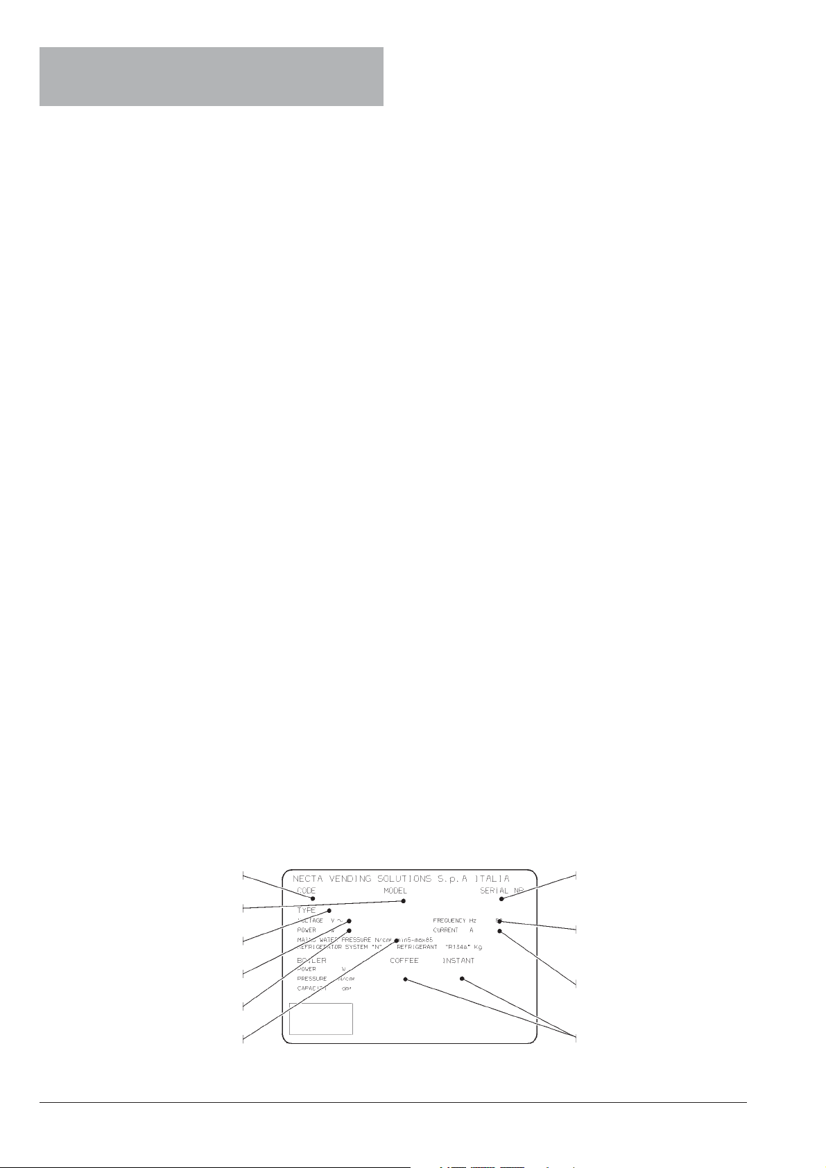
Every machine is identified by its own serial number,
indicated on the rating plate attached inside the cabinet on
the right side.
This plate (see Figure below) is the only one acknowledged by the manufacturer and indicates all of the data
which readily and safely gives technical information supplied by the manufacturer. It also assists in spare parts
management.
IN CASE OF FAILURE
In most cases, any technical problems are corrected by
small repair operations; however, before contacting the
manufacturer we recommend that this manual be read
carefully.
Should there be serious failures or malfunctions, contact
the following:
NECTA
VENDING SOLUTIONS SpA
Via Roma 24
24030 Valbrembo
Italy - Tel. +39 - 035606111
TRANSPORT AND STORAGE
To prevent any damage, special care should be taken
when loading or unloading the vending machine.
The machine can be lifted by a motor-driven or manual fork
lift truck, and the blades are to be placed underneath the
machine.
Do not:
- overturn the vending machine;
- drag the vending machine with ropes or similar;
Product code
Model
Type
Operating voltage
Absorbed power
Water mains characteristics
- lift the vending machine by its sides;
- lift the vending machine with slings or ropes;
- shake or jolt the vending machine and its packing.
The machine should be stored in a dry room where the
temperature remains between 0°C and 40°C.
Using the original packing, no more than 2 machines can
be stacked one on top of the other and must always kept
upright as indicated by the arrows on the packing.
Serial number
Frequency
Current
Boiler data
© by NECTA VENDING SOLUTIONS SpA 03-2003 217 00
2
Page 7
POSITIONING THE VENDING MACHINE
WARNING FOR SCRAPPING
The vending machine is not suitable for outdoor installation. It must be positioned in a dry room where the temperature remains between 2°C and 32°C, and not where water
jets are used for cleaning (e.g. in large kitchens, etc.).
The machine must be placed on the special support
cabinet, which houses the liquid waste tray, the water
supply device, the payment system and, in the case of very
hard water, the softener cartridge.
The machine should be placed close to a wall, so that the
back panel is at a minimum distance of 4 cm from it and
correct ventilation may be ensured. The machine must
never be covered with cloth or the like.
The machine should be positioned with a maximum inclination of 2°.
If necessary provide proper levelling by way of the adjustable feet included.
Important notice!!
Access to the machine interior for maintenance and/or
repairs is via the back panel.
Therefore the machine is designed to be rotated, thus
allowing removal of the back panel.
Installation on the cabinet
The machine must be placed on the special support
cabinet, which houses: the liquid waste tray, the water
supply kit, the payment system and, in the case of very
hard water, the softener unit.
Whenever the machine is to be scrapped, the laws in force
regarding environment protection should be strictly observed. More specifically:
- ferrous and plastic materials and the like are to be
disposed of in authorized areas only;
- insulating materials should be recovered by qualified
companies.
TECHNICAL SPECIFICATIONS
DIMENSIONS
WARNING FOR INSTALLATION
The machine installation and the following maintenance operations should be carried out by qualified
personnel only, who are trained in the correct use of
the machine according to the standards in force.
The machine is sold without payment system, therefore
the installer of such system has sole responsibility for any
damage to the machine or to things and persons caused by
faulty installation.
The integrity of the machine and compliance with the
standards of the relevant systems must be checked at
least once a year by qualified personnel.
All packing materials shall be disposed of in a manner
which is safe for the environment.
PRECAUTIONS IN USING THE MACHINE
The following precautions will assist in protecting the
environment:
- use biodegradable products only to clean the machine;
- adequately dispose of all containers of the products
used for loading and cleaning the machine;
- switch the machine off during periods of inactivity, thus
achieving considerable energy savings.
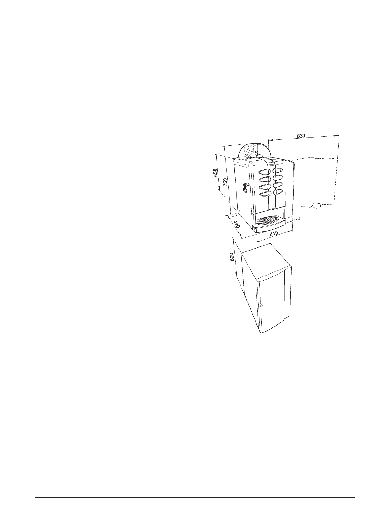
Height 650 mm
Height with container 750 mm
Width 410 mm
Depth 490 mm
Overall depth with door open 830 mm
Height of cabinet 820 mm
Weight 38 Kg
Power supply voltage 220 V~
Power supply frequency 60 Hz
Installed power 1300 W
© by NECTA VENDING SOLUTIONS SpA 03-2003 217 00
3
Page 8
CUP DISPENSER
Suitable for cups with a rim diameter of 73-74 mm. with a
capacity of approximately 170 cups.
PAYMENT SYSTEM
The machine is supplied with all prearrangement for the
MDB protocol.
The machine can accommodate the “cashless” payment
system, while the “change-giver” payment system must be
installed in the support cabinet.
SALES PRICES
A different programmable price can be set for each single
selection; the standard setting has the same sales price for
all selections.
COIN BOX
Made of plastic with lock as optional accessory.
WATER SUPPLY
A self-contained water supply device (with a 15-litre tank)
is installed in the support cabinet.
AVAILABLE ADJUSTMENTS
- Grade of grinding for espresso coffee
- Coffee and water doses by volume
- Time adjustment for instant products
- Temperature control
Factory setting on the correct operating temperature. A
trimmer on the control board is used to make small corrections (if necessary).
CONTROLS
CAPACITY OF CONTAINERS
)gK(sreniatnocfoyticapaCosserpsE
snaebeeffoC2
kliM8.0
etalocohC4.1
).N(srerritS561
POWER CONSUMPTION
The machine power consumption depends on many factors, such as the temperature and ventilation of the room
where it is installed, the inlet water and boiler temperature,
etc.
With an ambient temperature of 22° C the following power
consumption levels resulted:
osserpsE
snoitcelesknird03l69.0
erutarepmetknirdegarevAC°2.67
noitpmusnocrewoP
erutarepmetgnitarepohcaeroThW6.82
yb-dnatsfoh42hW4141
ruoh/snoitceles03hW2.171
The above power consumption calculated from average
data should only be taken as an indication.
- Presence of cups
- Presence of water
- Presence of coffee
- Operating temperature reached
- Cup release microswitch
SAFETY DEVICES
- Differential switch
- Door switch
- Presence of coffee waste tray
- Manual-reset boiler safety thermostat
- Air-break float jammed
- Timer protection for:
Pump
Coffee unit ratiomotor
Coffee grinder
- Overheating protection for:
Doser units
Coffee unit ratiomotor
Magnets
Pump
Electric mixers
Coffee grinder motor
- Fuse protection for
Main electrical circuit
Board power supply transformer
ACCESSORIES
A wide range of accessories can be installed on the
machine to vary its performance:
The installation kits are supplied with their own installation
and test instructions, which must be strictly observed to
ensure the machine safety.
Important notice!!
The use of kits which are not approved by the manufacturer
of the vending machine does not guarantee compliance
with safety standards, especially for energised parts.
The manufacturer declines all responsibility for the use of
non approved components.
Installation and the following testing operations must
be carried out exclusively by personnel who have a
specific knowledge of the machine functions from a
point of view of electrical safety and health regulations.
© by NECTA VENDING SOLUTIONS SpA 03-2003 217 00
4
Page 9
Chapter 1
LOADING AND CLEANING
DOOR SWITCH
When opening the door a special switch disconnects the
power from the machine electrical system to allow the
operations described below, regarding filling and routine
cleaning.
All operations requiring the machine to be energized
should be carried out by qualified personnel ONLY,
informed about the specific risks of such situation.
MAINTENANCE AND DISINFECTION
According to current safety and health rules and regulations, the operator of an automatic vending machine is
responsible for the hygiene and the maintenance of the
foodstuff circuits, to prevent formation of bacteria.
At installation the hydraulic circuits and the parts in
contact with foodstuff should be fully sanitised to
remove any bacteria which might have formed during
storage.
It is advisable that specific sanitising agents (such as
chlorine-based detergents or similar) are used for cleaning
also the surfaces which are not directly in contact with
foodstuff.
Some parts of the machine can be damaged by strong
detergents.
The manufacturer declines all responsibility for any damage to persons caused by non-compliance with current
health regulations.
Before starting any maintenance operations requiring
parts of the unit to be removed, the machine must
always be switched off.
USING THE VENDING MACHINES OF HOT
DRINKS IN OPEN CONTAINERS
(Ex.: plastic cups, ceramic cups, jugs)
Vending machines for drinks in open containers should be
used only to sell and dispense drinks obtained by:
- brewing products like coffee and tea;
- reconstituting instant and lyophilised products;
These products should be declared by the manufacturer
as “suitable for automatic vending” in open containers.
The dispensed products should be consumed immediately. They should never be preserved and/or packed
for later consumption.
Any other use is unsuitable and thus potentially dangerous.
CONTROLS AND INFORMATION
The user controls and information are located on the
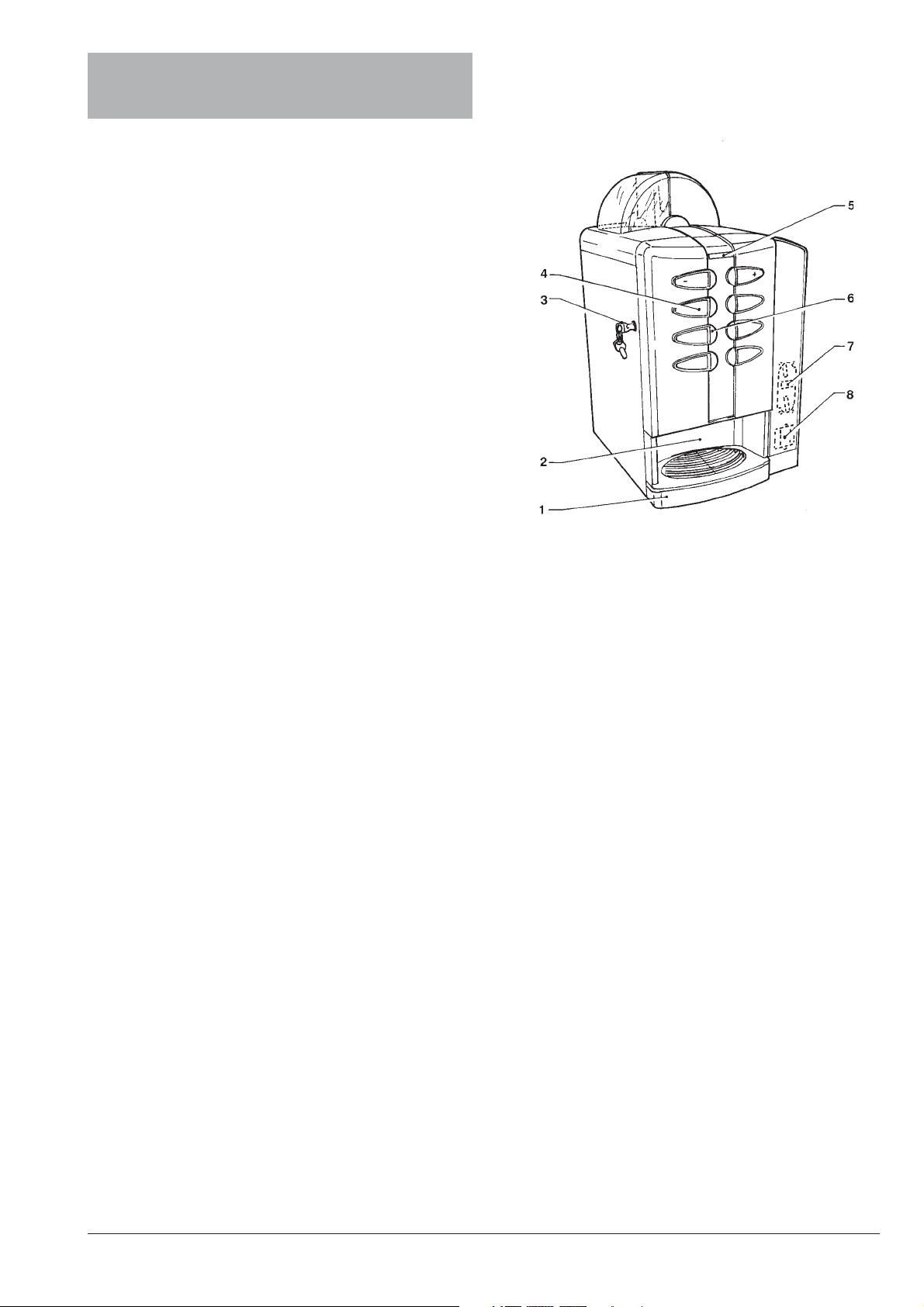
outside of the door (see Fig. 1).
Fig. 1
1 - Liquid waste tray
2 - Dispensing compartment
3 - Lock
4 - Spaces for product labels
5 - Alphanumeric display
6 - Selection buttons
7 - Prearrangement for front validator
8 - Prearrangement for “cashless” payment systems
The labels with the selection menu and the operating
instructions supplied with the machine must be inserted at
the time of installation, referring to the selection dose table.
The Programming button, used to access the machine
functions, is located on the internal side of the push-button
board.
Press the button once to set the machine to “Maintenance”
mode;
press the Programming button twice to set the machine to
“Programming” mode.
When in “Programming” mode press selection buttons No.
3 and No. 6 in a short sequence to start filling the machine
hydraulic system.
NOISE LEVEL
The continuous, weighted equivalent acoustic pressure
level is below 70 dB.
© by NECTA VENDING SOLUTIONS SpA 03-2003 217 00
5
Page 10
LOADING CUPS
To load the cups do as follows:
- open the door and remove the cover from the cup
dispenser;
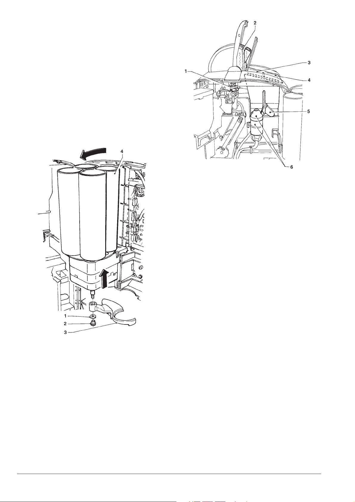
- slightly lift the cup dispenser and tilt it (see Fig. 2);
- do not rotate the columns during the loading opera-
tions;
- load the columns with cups, without exceeding the
dispenser height;
- re-engage the cup dispenser and replace the cover;
- close the machine and make a test selection.
Fig. 3
1 - Coffee hopper shutter
2 - Coffee hopper
3 - Milk container
4 - Chocolate container
5 - Powder chute
6 - Powder feeder
Fig. 2
1 - Spacer washer
2 - Knurled nut
3 - Cup shift arm
4 - Cup container
LOADING COFFEE
The cover can be opened only with the door open.
Lift the cover and fill the hopper with coffee, ensuring that
the shutter is fully open (see Fig. 3).
LOADING SUGAR AND
INSTANT PRODUCTS
The covers can be opened only with the door open.
After lifting their cover, fill the single containers with the
appropriate products, taking care not to compress them to
prevent packing. Make sure the products do not contain
any clots.
When handling the sugar/stirrer dispenser shelf, ensure that the key (see Fig. 8) is completely rotated
clockwise to prevent the lock bolt from interfering with
the stirrer stacker.
LOADING STIRRERS
Remove the cover and the stirrer weight (see Fig. 8), then
insert the stirrers to be loaded.
Remove the paper strip, ensuring that the stirrers are all
placed horizontally.
Replace the stirrer weight and the cover.
The stirrers must be burr free and not curved.
© by NECTA VENDING SOLUTIONS SpA 03-2003 217 00
6
Page 11
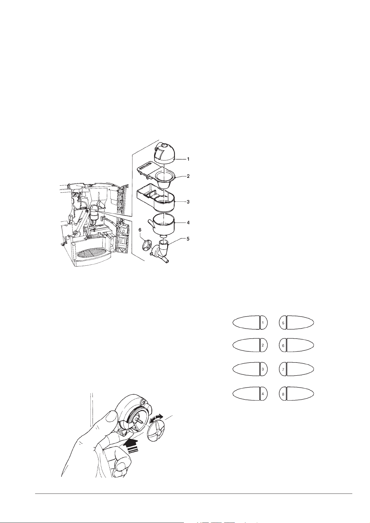
SANITISING THE MIXERS
AND FOODSTUFF CIRCUITS
When installing the machine, and then at least once a week
or even more frequently according to the use of the
machine and the quality of the inlet water, the mixers and
the dispensing conduits must be thoroughly sanitised
(cleaned and disinfected), to guarantee proper hygiene of
the dispensed products.
The parts to be cleaned are as follows:
- powder deposit drawers, mixer and instant drink
dispensing conduit;
- coffee dispensing spout;
- sugar chute;
- dispensing compartment;
- wash all parts with detergent being sure that all visible
residue and product layers are mechanically removed,
using a brush if necessary;
Disinfection should be carried out using chlorine-based
detergents.
- soak all components for approx. 20 minutes in a
container filled with the previously prepared chlorinebased detergent;
- reinstall the feeders and the water funnels;
- reinstall the powder deposit drawers and the powder
funnels after thoroughly drying them.
After reinstalling all parts the following is however
required:
- add a few drops of the chlorine-based detergent in the
mixer;
- using the mixer cleaning function with the door closed,
thoroughly rinse all components to ensure that all
residue of the detergent solution is removed.
MIXER CLEANING
Fig. 4
1 - Powder feeder
2 - Powder funnel
3 - Powder deposit drawer
4 - Water funnel
5 - Feeder
6 - Mixer impeller
- remove the powder and the water funnels, the feeders,
the powder deposit drawers and the mixer wheels from
the mixers (see Fig. 4);
- in order to remove the wheels, block the disk fitted on
the mixer shaft with a finger (see Fig. 5);
The mixer must cleaned daily and every time the machine
is refilled to prevent clogging of the mixer if any product is
accidentally spilled during refilling.
It must be cleaned also after the mixer sanitasing operations, as described in the relevant chapter.
The mixer is cleaned with the door closed, doing as follows:
- press button 8 for 2 seconds. The display will show the
request to enter the password;
- press in a quick succession buttons 4 4 8 8 to start
cleaning.
Fig. 5
© by NECTA VENDING SOLUTIONS SpA 03-2003 217 00
7
Page 12
CLEANING THE WATER SUPPLY TANK
CLEANING THE WASTE TRAYS
The water tank, positioned in the support cabinet, must be
sanitised at least weekly with the chlorine-based detergents used for the mixers, being sure that all visible residue
and product layers are mechanically removed, using a
brush if necessary;
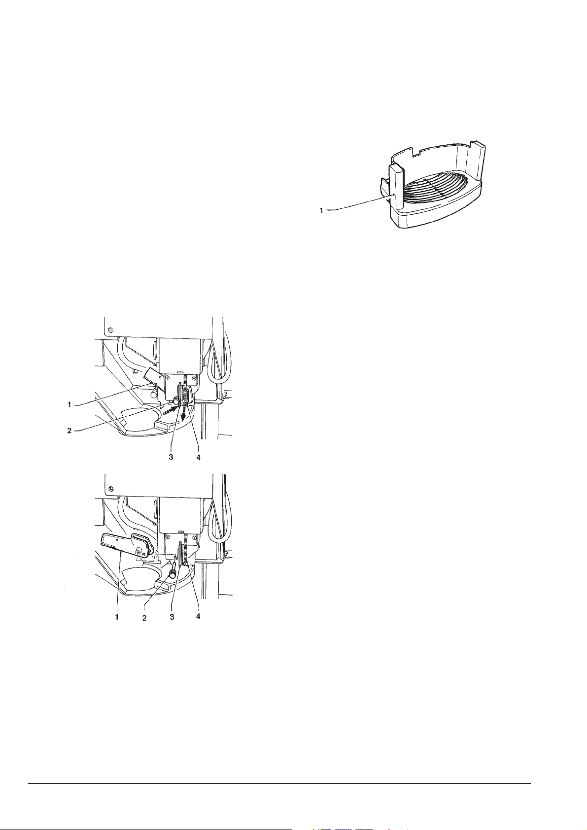
CLEANING THE SUGAR DISPENSER
For models with sugar dispensed directly into the cup, the
sugar dispensing system must be cleaned periodically
using hot water (see Fig. 6) proceeding as follows:
- release the return spring;
- lift the flexible lever to free the pin;
- remove the pin and the dispensing spout;
- after cleaning, thoroughly dry all parts and reinstall
them in the reverse order.
The liquid waste tray, located in the dispensing compartment, and the coffee waste tray, located in the support
cabinet, as well as the liquid waste container in the support
cabinet, must be emptied and rinsed at each refill.
At least once a week they must be sanitised using coffee
machine detergents and mechanically removing all visible
residue and product layers.
Fig. 7
1 - Dispensing compartment drip tray
CLEANING THE CUP SHIFT ARM
The cup shift arm must be cleaned periodically by removing it from the machine. In order to remove it, completely
undo the fastening knurled nut (see Fig. 2).
When reinstalling it, ensure that the spacer washer is
positioned correctly.
Fig. 6
1 - Sugar dispensing spout
2 - Pin
3 - Flexible lever
4 - Return spring
WEEKLY CLEANING OF THE COFFEE
UNIT
Every time coffee is refilled, or at least once a week, any
powder residue should be removed from the external parts
of the coffee unit, particularly from the coffee funnel area
(see Fig. 16).
SUSPENDING FROM USE
If for any reason the machine is switched off for a period
exceeding the use-by date of the products, the following
will be necessary:
- completely empty the containers and thoroughly wash
them with the chlorine-based detergents used to clean
the mixers.
- completely empty the coffee doser unit by dispensing
coffee until the empty condition is indicated.
- completely empty the hydraulic system.
© by NECTA VENDING SOLUTIONS SpA 03-2003 217 00
8
Page 13
Chapter 2
INSTALLATION
The machine installation and the following maintenance operations should be carried out by qualified
personnel only, who are trained in the correct use of
the machine and are aware of the specific risks of such
operations.
To energize the system with the open door, simply insert
the special key into the slot (see Fig. 8).
The door can be closed only after removing the key.
Fig. 8
1 - Door lock bolt
2 - Door lock
3 - Stirrer stacker adjusting slots
4 - Door switch
5 - Stirrer weight
The machine must be installed in a dry room with
temperature between 2°C and 32°C.
At installation the hydraulic circuits and the parts in
contact with foodstuff should be fully sanitised to
remove any bacteria which might have formed during
storage.
UNPACKING THE VENDING MACHINE
After removing the packing from the machine and from the
support cabinet, ensure that the machine and all other
equipment are intact.
If in doubt do not use the machine.
No packing elements (i.e. plastic bags, polystyrene
foam, nails, etc.) should be left within the reach of
children, as they are potentially dangerous.
Packing materials must be disposed of in authorised
containers and the recyclable ones must be recovered by
qualified companies.
Important notice!!
The machine should be positioned with a maximum inclination of 2°.
If necessary provide proper levelling by way of the adjustable feet included (see Fig. 9).
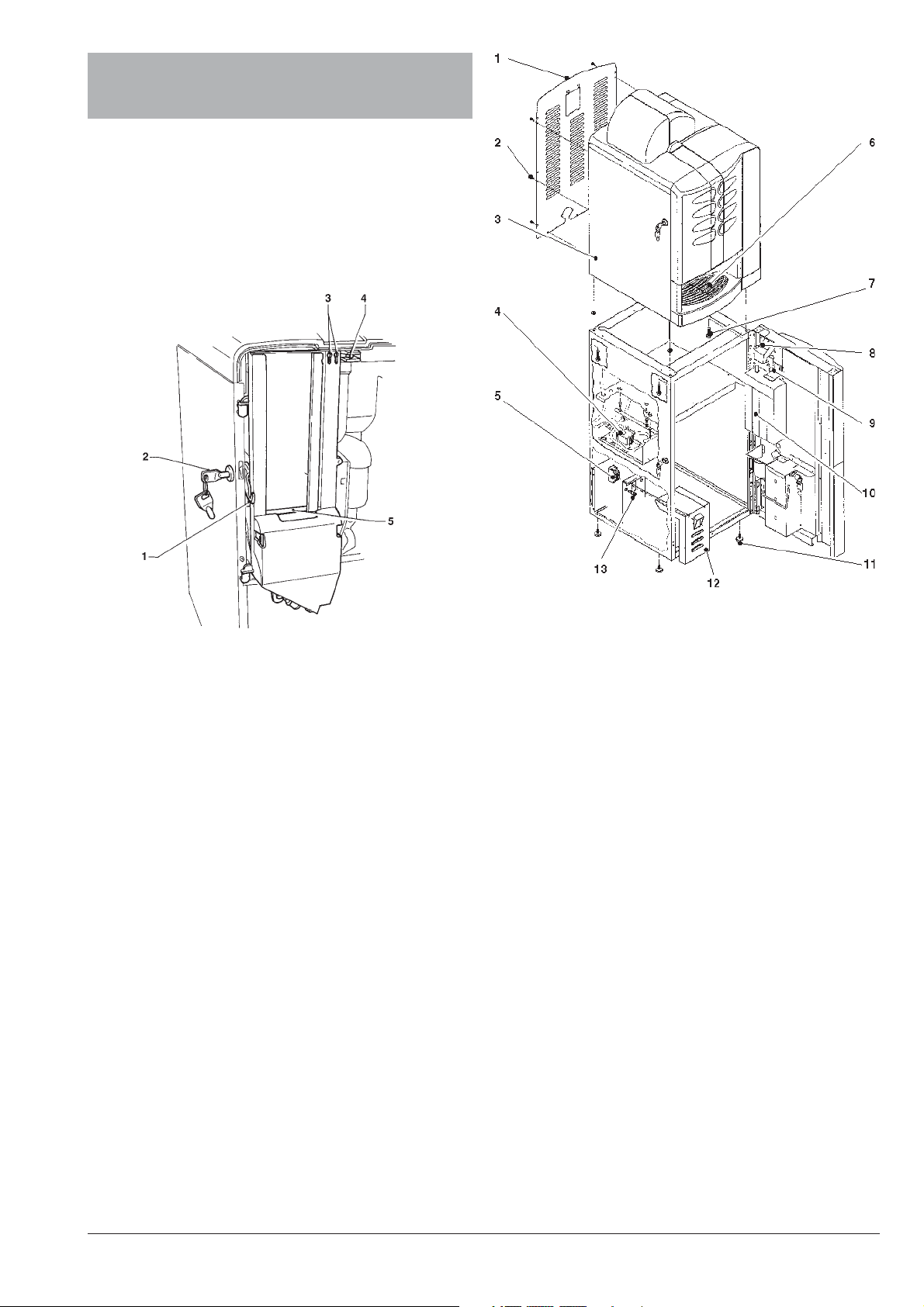
Fig. 9
1 - Back panel
2 - Back panel securing screws
3 - Wiring connectors’ zone
4 - Water supply pump
5 - Differential switch
6 - Dispensing compartment drip tray
7 - Machine securing screws
8 - Coin chute
9 - Selector opening lever
10 - Coin mechanism
11 - Adjustable feet
12 - Removable lid
13 - Fuses
MACHINE AND CABINET ASSEMBLY
In order to assemble cabinet and machine, do as follows:
- Install the adjustable feet to the cabinet and adjust
them to level the cabinet.
- Place the machine onto the cabinet and secure it using
the special screws provided.
- Remove the back panel from the machine, undoing the
securing screws.
- Connect the wires from the transformer and from the
water supply device, located inside the cabinet, to the
corresponding connectors inside the machine.
- Lay the cable of the payment system, located inside
the machine, from the top panel of the cabinet to the
coin slot zone.
© by NECTA VENDING SOLUTIONS SpA 03-2003 217 00
9
Page 14
- Fit the water supply hose onto the hose connector (see
hydraulic diagram) located on the middle shelf of the
cabinet.
- Make sure that the drain boss in the dispensing
compartment tray is punched and lines up with the
drain tube in the cabinet.
INSTALLING THE PAYMENT SYSTEM
The machine is sold without payment system, therefore the installer of such a system is responsible for
any damage to the machine or to things and persons
caused by faulty installation.
The machine is electrically pre-set for the installation of
MDB payment systems, and namely:
- coin acceptor or “validator”
- change-giver coin mechanisms or “changer”
- bill accepter or “bill validator”
- key / magnetic card reader or “cashless”
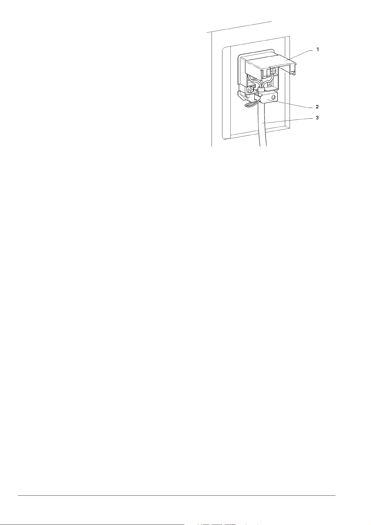
Fig. 10
1 - Lift cover
2 - Cable clamp
3 - Power supply cable
that can be used in various combinations.
Compatibility for housing the payment systems must
be ascertained by and under the sole responsibility of
the installer.
When switched on, the machine goes through a control
rotine to determine
which payment systems are actually
installed and therefore configure the correct system.
CONNECTING THE MACHINE TO THE
POWER SUPPLY
The machine operates under a single-phase 220 V~ 60 Hz
voltage and is protected by 10 A fuses, located inside the
support cabinet (see Fig. 9).
Before making the connection, ensure that the rating
corresponds to that of the power grid, and more specifically:
- the supply voltage rating must be within the range
recommended for the connection points;
- the main switch should be capable of withstanding the
peak load required, and at the same time ensure
proper omnipolar disconnection from the power grid
with an opening gap of the contacts of at least 3 mm;
the main switch is protected by a differential switch.
The switch, the power outlet and the plug must be
located in an easily accessible position.
The power supply cable is of the type with a two-pole
straight plug of the non-detachable type. Any replacement
of the power supply cable should be made by qualified
personnel only, using cables of the type H05 RN - F or H05
V V - F with a section of 3x1-1.5 mm2.
The electrical safety of the machine is ensured only
when it is correctly connected to an efficient earthing
system according to the safety standards in force.
This fundamental safety requirement must be duly verified,
and if in doubt the system must be carefully tested by
qualified technicians.
Do not use adapters, multiple sockets and/or extensions.
Before switching the machine on, ensure that the water
tank is correctly filled.
THE MANUFACTURER DECLINES ALL RESPONSIBILITY FOR ANY DAMAGE CAUSED BY NON-COMPLIANCE WITH THE ABOVE MENTIONED SAFETY
RULES.
DIFFERENTIAL SWITCH
The differential switch has the following characteristics:
- maximum current: 15 A
- maximum tripping current to earth: 15 mA
- breaking capacity: 1.5 KA
This switch is fitted for the purpose of protecting from
any overcurrent and earth leakage, also protecting persons from contact with live parts.
If the switch is triggered again when is reset after
tripping, the system must be tested by qualified personnel.
© by NECTA VENDING SOLUTIONS SpA 03-2003 217 00
10
Page 15

DOOR SWITCH
When opening the door a special microswitch (see Fig. 8)
disconnects the power from the machine electrical system.
The trasformer inside the support cabinet remains energised.
The differential switch must be used to disconneted it.
With the door open, there is no access to energised
parts. Inside the machine, the only parts that stay
energised are those protected by covers and carrying
a plate with the warning “Disconnect the power before
removing the protective cover”.
Before removing such covers disconnect the machine
from the power grid.
To energize the system with the open door, simply insert
the special key into the slot (see Fig. 8).
All operations which require the machine to be energised with the door open must be carried out by
qualified personnel who are aware of the specific risks
of such condition.
WATER SOFTENER UNIT
The machine is sold without water softener.
Should the water be very hard, a water softener cartridge
can be installed, using the connections provided in the
hydraulic circuit.
The cartridge should be replaced according to the manufacturer’s instructions.
INSERTING THE PRODUCT LABELS
The menu and instruction labels are supplied with the
machine and must be inserted at the time of installation
according to the layout and to the language (see “selection
dose” table).
LENGTH OF STIRRERS
The correct installation position of the stirrer stacker (see
Fig. 8) must be checked according to the length of the
stirrers to be used (105 mm by default).
FILLING THE WATER SYSTEM
When the machine is switched on the condition of air-break
(full or empty), pump (electrical functioning and water flow)
and boiler (pressure).
When the machine is completely empty the “No Water”
failure is indicated.
When the programming button located on the internal side
of the push-button board (see Fig. 19) is pressed twice the
machine will be set to “Programming” mode; when pressing the selection buttons 3 and 6 in a sequence, the
machine will go through an installation cycle, and namely:
- the water supply pump is started to fill the air-break;
- the milk solenoid valve is opened so that the air may
be bled from the boiler and 400 cc. of water filled.
- the message “Installation” will be shown on the display
for the entire duration of the cycle;
N.B.:If there is no water flow from the mains during the
installation cycle, the machine will stop until water is
resumed or the machine is switched off.
IMPORTANT NOTICE!!!
If a considerable amount of air bubbles is formed in the
water system, for example during maintenance, it is possible that an installation cycle need to be started when the
machine is switched on.
INITIALISING
The machine was designed for different market needs.
The software is capable of managing all possible configurations.
For this reason, before starting the machine, some
parameters must be set.
“Country”
intended as type of base doses for the different selections
The available “Countries” are:
- Korea
“Layout”
A number of Button/Selection combinations to choose
from is provided for each dose type model (the combinations available for each layout are indicated in the dose
selection table supplied with the machine).
“Tank”
It is possible to define whether or not the water supply is
form the tank in the cabinet.
The change in operating time of the power users is compensated automatically.
© by NECTA VENDING SOLUTIONS SpA 03-2003 217 00
11
Page 16
COFFEE UNIT OPERATION
COFFEE DISPENSING CYCLE
After each time the machine is switched on, upon the first
espresso coffee based selection, the coffee unit is rotated
completely before the normal cycle, too ensure that the
device is in the correct start position.
When selecting coffee, the grinder is started and will
continue until the coffee doser chamber is full (see Figure
14).
When the doser unit is full, the ground coffee dose is
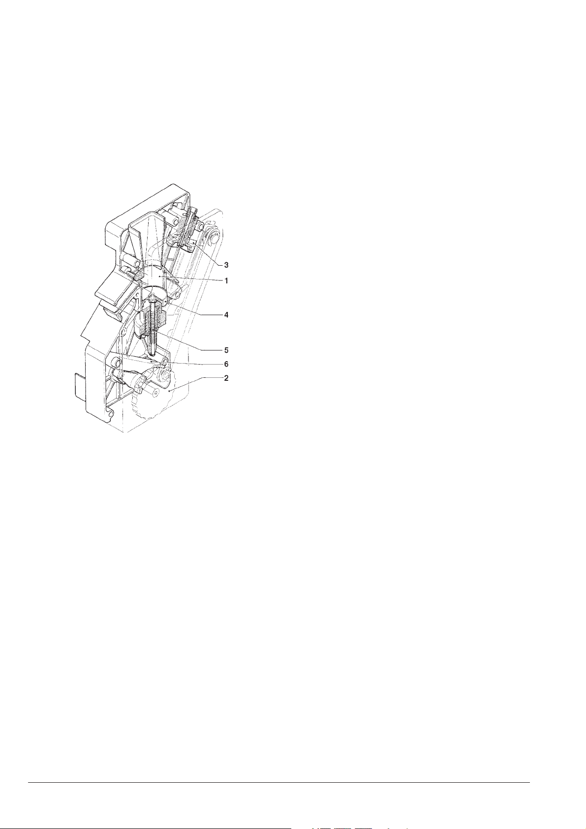
released into the coffee unit.
The coffee falls into the vertical brewing chamber (1) (see
Fig. 11).
The ratiomotor handle engaged with the disk (2) located
outside of the assembly rotates by 180°, making the brew
chamber swing and lowering the upper piston (3) (see
Figure 12).
Due to the water pressure, the pre-brewing spring (5) sinks
and the lower piston (4) goes down 4 mm, thus forming a
water cushion which allows an even use of the coffee dose.
At the end of the dispensing cycle and during a pause of 3
seconds, the pre-brewing spring (5) will discharge the
water through the third way of the dispensing solenoid
valve, lightly pressing the used coffee dose.
By completing its rotation, the ratiomotor makes the swinging lever (6) lift the pistons and the coffee dose.
At the same time, when the brewing chamber returns to its
vertical position, the scraper on the coffee hopper stops the
used coffee dose and drops it.
The lower piston now returns to the bottom dead centre.
Fig. 11
1 - Brewing chamber
2 - External disk
3 - Upper piston
4 - Lower piston
5 - Pre-brewing spring
6 - Swinging lever
© by NECTA VENDING SOLUTIONS SpA 03-2003 217 00
12
Page 17
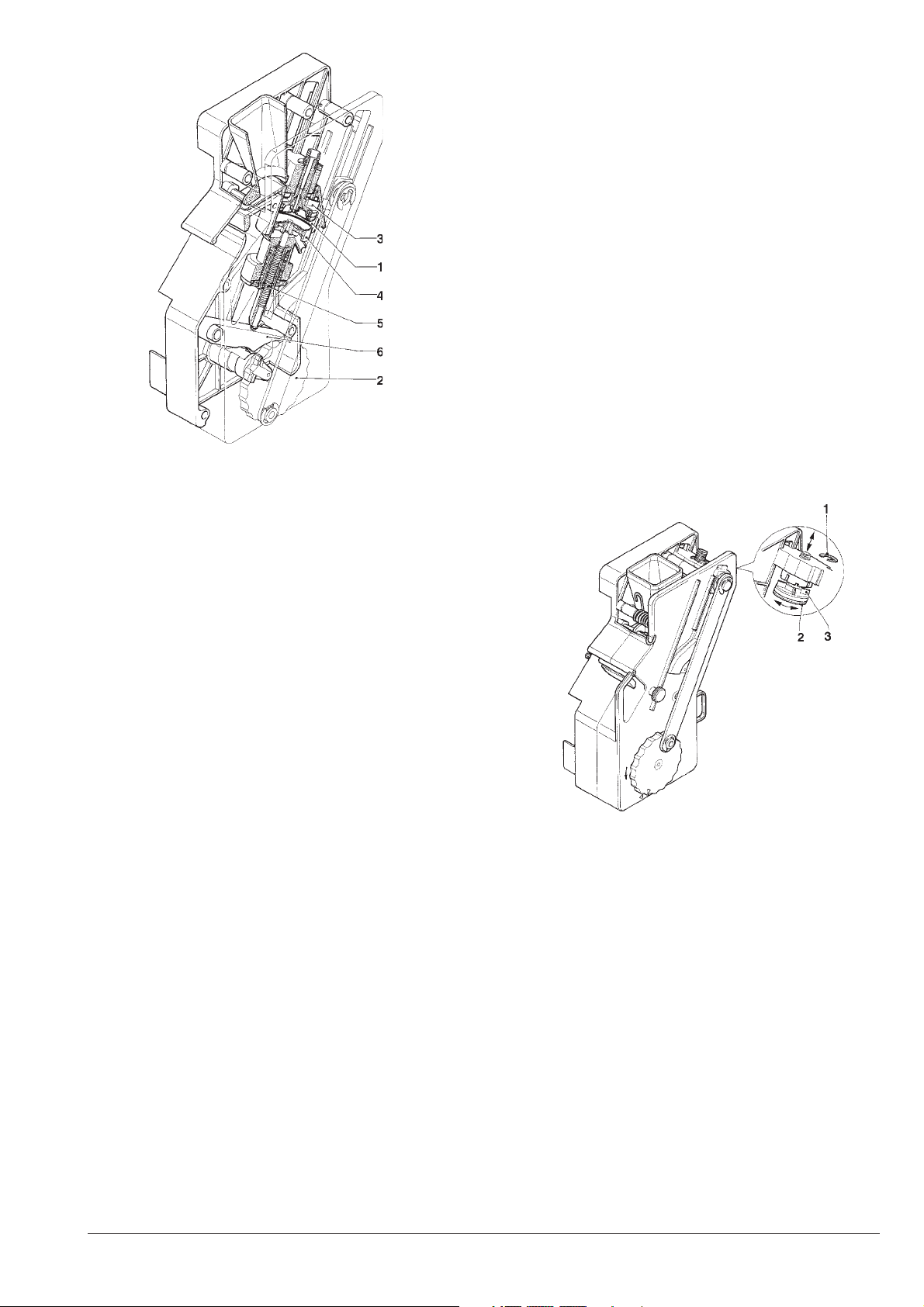
Fig. 12
1 - Brewing chamber
2 - External disk
3 - Upper piston
4 - Lower piston
5 - Pre-brewing spring
6 - Swinging lever
STANDARD SETTINGS
The vending machine is supplied with the following settings:
- coffee temperature (at the spout) approx. 70÷80°C;
- instant product temperature (at the spout) approx.
70÷80°C;
The machine standard settings assign the same price,
expressed in number of basic coins, to all selections.
ADJUSTING THE BREWING CHAMBER
VOLUME
When the upper piston is correctly positioned, the coffee
unit can operate with coffee doses of 5.5 to 8.5 g.
To change the piston position (see Fig. 13) do as follows:
- remove the snap ring from its seat;
- place the piston in the proper adjusting notches:
.less deep notches for 5.5 to 7.5 g doses;
.deeper notches for 6.5 to 8.5 g doses.
CHECKING AND ADJUSTING
THE MACHINE SETTINGS
To get the best results from the product used, the following
should be checked:
For coffee
That the used coffee dose is lightly compressed and
damp.
The grade of grinding of ground coffee.
The dose weight of ground coffee.
The dispensing temperature.
The water dose.
For instant products
The dose weight of the instant products.
The drink temperature.
The water dose.
Should the standard settings need to be changed, proceed
as indicated in the next sections of this manual.
The weight of instant products, the water dose and temperature are directly controlled by the microprocessor.
To adjust them it is therefore necessary to follow the
programming procedures.
Fig. 13
1 - Anello elastico
2 - pistone superiore
3 - alette di riferimento
WATER TEMPERATURE CONTROL
If the boiler temperature is to be changed, adjust the
special trimmer (see Fig. 17) keeping in mind that:
- tightening increases the temperature;
- loosening reduces the temperature;
- every 2 turns the temperature varies by approx. 1°C.
© by NECTA VENDING SOLUTIONS SpA 03-2003 217 00
13
Page 18
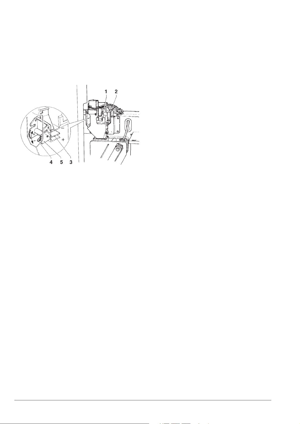
ADJUSTING THE GRADE OF GRINDING
OPERATING MODES
When a variation in the grade of grinding is desired, turn the
relevant adjusting knob on the grinder (see Fig. 14) and
more specifically:
- turn the knob anticlockwise for coarser grinding;
- turn the knob clockwise for finer grinding.
For optimum results, it is advisable to vary the grade of
grinding with the coffee grinder motor running.
Fig. 14
1 - Macinino
2 - Manopola di regolazione macinatura
3 - Regolo dose
4 - Levetta regolazione dose
5 - Tacche di riferimento
Three different operating modes are provided for the
machine; the buttons will have different functions according to the machine operating mode.
The available operating modes are indicated in the following table:
DISPLAY FUNCTIONS
Normal mode
“Ready for use” coins accepted
products dispensed
Maintenance
“Maintenance” test dispensing
machine maintenance
Programming mode
“Programming” programming
NORMAL OPERATING MODE
When switching the machine on, the display will show the
message “Rev. X.X” (X.X indicates the software release
number) for a few seconds, after which the machine will be
set to normal operating mode.
The massages displayed according to the operation being
carried out can be the following:
N.B.: After adjustment of the grade of grinding, at least
2 test selections must be performed in order to check
the new grade of grinding for ground coffee:
The finer the grade of grinding the longer the time necessary for dispensing the coffee and vice versa.
ADJUSTING THE COFFEE DOSE
The dose adjusting lever can be positioned in one of the 6
reference notches bearing in mind that:
- the dose is increased by lifting the lever:
- the dose is reduced by lowering the lever:
- every notch changes the dose by approx. 0.25 g.
In addition, when the lever is fully rotated upwards, the
ratchet can be released from the groove in the dose
regulator (see Fig.14) and replaced into a different groove
to change the average dose setting to:
- low 6 g ± 0,5
- medium 7 g ± 0,5
- high 8 g ± 0,5
To take the dose just remove the coffee unit and press
button “6” from “Special functions” of the “maintenance”
menu (see relevant section).
Important notice!!!
DISPLAY FUNCTION
“Ready for use” Machine ready
“Price:....” Price display of
selected product
“Credit:.....” Displaying credit inserted
“Out of service” Machine switched off
“Drink in process” Drink preparation
“Temperature” Wait time before reaching
operating temperature
“Sel. Disabled” Selection disabled
“Coffee off” Coffee unit out of service
“Take” Drink ready
To refit the coffee unit, pay special attention to the
piston position. Reference notches on the external
disk and on the unit case should match (see Fig. 16).
© by NECTA VENDING SOLUTIONS SpA 03-2003 217 00
14
Page 19
PRE-SELECTIONS
According to the layout set at the time of initialising buttons
“1” and “5” can be assigned the function of sugar dose
variations; in this case the display will indicate
“Sugar
median dose. Each time buttons “1” (minus) and “5” (plus)
are pressed the dispensed dose varies by 1/4 of the
median dose.
" which represents the programmed
Scroll through the menu with the " "and " " buttons to
highlight the following functions:
"Complete Sel.” Test dispensing complete
with cup sugar and stirrer
“Powd. only” Dispensing powder only
“Water only” Dispensing water only
MAINTENANCE MODE
When the programming button located on the internal side
of the push-button board (see Fig. 19) is pressed once the
machine will go to “Maintenance” mode.
The message “Maintenance” is displayed for approx. two
seconds and then the first option of the “Statistics” menu is
presented, permitting data management.
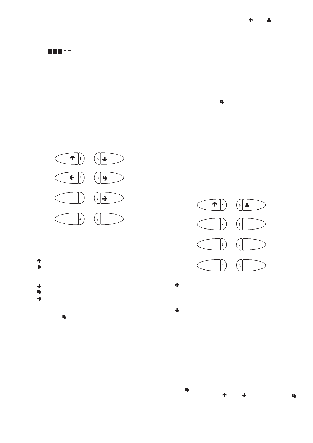
When in maintenance mode the buttons have the following
functions:
“No Accessories” Test dispensing without
cup sugar and stirrer
When pressing button " " the selection buttons will take on
the original function for 4 seconds, permitting the test
dispensing provided for each function.
N.B. For espresso coffee based selections, only the
additions are dispensed with the partial dispensing of
powder and water; if a selection requires no addition
the message “Sel. disabled”, indicating a disabled
selection, will be displayed.
SPECIAL FUNCTIONS
When the display shows “Special functions” the buttons
take on the following functions:
1 - Previous function / Increase data item (+1)
2 - Exit function / Cancel change
3 4 5 - Next function / Decrease data item (- 1)
6 - Confirm function / confirm data
7 - Change data item
8 -
Press button " " to access the following functions:
- Display statistics
- Print statistics
- Delete statistics
- Display selection counter
1 - Previous function
2 - Grind and release a coffee dose
3 - Dispense sugar
4 - Autotest
5 - Next function
6 - Rotate coffee unit
7 - Release cup
8 - Empty air-break
In order to weigh the coffee dose using the “Grind and
release” function, the coffee unit must be remover. The
function stays enabled anyway.
If a coffee dose is accidentally released with the unit
installed, the unit will have to be rotated to unload the
excess coffee.
According to the type of pre-selection set in the layout,
button " " allows access to the sugar dose, which can be
adjusted with buttons " " and " "; pressing button " "
again will release the set sugar dose.
© by NECTA VENDING SOLUTIONS SpA 03-2003 217 00
15
Page 20

AUTOTEST
This function allows testing of the main machine components.
Before carrying out this operation, remove the waste tray
and the powder containers and disassemble the coffee
unit.
Press button “4” and the message “AUTOTEST” will be
start blinking.
Press button “2” to cancel the operation, confirm with
button “6” to start the autotest cycle.
In a sequence:
- the doser devices are activated for 2 seconds
- the mixers are activated for 2 seconds
- a cup is released
Aud. 1 Money in the tubes
Money present in the change tube that moment
Aud. 2 Money to the tubes
Money sent to the change tubes
Aud. 3 Money to the box
Money sent to the coin box
Aud. 4 Change return
Total money returned
Aud. 5 Excess
Excess money. Extra amounts paid by the customer that
were not returned (in the event there was no money
available for return)
- a stirrer is released
- the coffee unit is rotated, coffee is ground and then
released when a full dose is reached.
- the waste tray is detected; the machine stops until the
waste tray is manually re-inserted
- the push-button panel is checked; the machine displays the number of the button which must be pressed
and waits for this to be done before going to the next
button (number 9 corresponds to the cleaning button).
EMPTYING THE AIR-BREAK
This function is used to partially empty the air-break,
dispensing water from the milk solenoid valve for 8 seconds before blocking the machine, to allow the machine to
be moved without spilling water; to restore normal functioning the machine must be switched off and then on.
Before moving the machine on a long distance, especially
if involving the use of a vehicle, the hydraulic system must
be emptied manually.
DISPLAYING THE STATISTICS
Press button " " when the display indicates the “Display
statistics” function; then the stored data will be sequentially
shown on the screen, and more precisely:
With setting to VALIDATOR or TOTALIZER
1 - counter by single selection;
2 - counter by single price;
3 - failure counter;
4 - counter by type of coin cashed;
5 - total cashed counter;
Aud. 6 Release tubes
Value of coins dispensed with the function “Tubes control”
Aud. 7 Loading tubes
Value of money cashed with the manual loading function
Aud. 8 Cash sales
Value of total sales with cash money (coins + bills)
Aud. 9 Cashed bills
Value of cashed bills
Aud. 10 Charge key
Value of money changed into the key
Aud. 11 Sales with key
Value of money cashed for dispensing with key.
PRINT STATISTICS
Connect an RS-232 serial printer with a Baud rate of 9600,
8 data bit, no parity, 1 stop bit to the serial port located on
the push button board, to print all the statistics described
in section “Displaying the statistics”. The hardcopy printout
will also contain the machine code number and the printout
progressive number.
The progressive hard-copy printout number can only be
reset by initialising the machine.
To connect the printer, do as follows:
- Press button “ ” when the display indicates the “Print
statistics” function and the message “Confirm?” will be
displayed;
- before confirming connect and switch on the printer;
- press the confirm button “ ” to start printing.
With setting to MDB
1 - counter by single selection;
2 - counter by single price;
3 - failure counter;
4 - MDB Audit; displaying in the actual currency of:
© by NECTA VENDING SOLUTIONS SpA 03-2003 217 00
16
Page 21
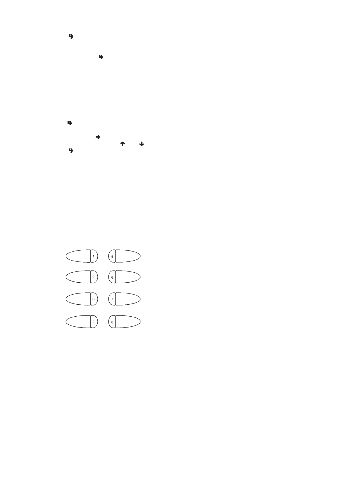
RESETTING THE FAILURE STATISTICS
PROGRAMMING
Press button “ ” when the display indicates the “Reset
statistics“ function, then the message “Confirm?” will be
start blinking.
Press the confirm button “ ”, the message “Working” is
displayed for a few seconds and all statistics regarding
failure counters are reset.
GENERAL COUNTER
The machine stores all selections in this counter, which
cannot be reset.
This function allows reading or displaying of the counter
when the machine is switched started.
Press button “ ” when the display indicates the “General
counter” function and the function status (ON/OFF) will be
displayed; press button “ ”, the status will start blinking
and then can be changed with the “ ”and “ ” buttons.
Press button “ ” again and the stored value will be displayed for 3 seconds.
CHANGE TUBES CONTROL
By accessing the “Tube control” function the change tubes
can be filled
or released manually. Confirm refilling, and the display will
indicate “Credit: ——”; insert the desired coin into the
selector and the display will indicate the value of the money
inserted.
The tubes can be emptied directly by pressing the selection buttons “1, 2, 3 and 4”.
Press button “8” to exit the function.
When the programming button located on the internal side
of the push-button board (see Fig. 19) is pressed twice the
machine will be set to “Programming” mode.
The message “Programming” is displayed for approx. 2
seconds, and then the first option of the programming
menu is displayed to activate the following functions:
“Present failures” current failure reading
“Water dose” water dose setting
“Powder dose” powder dose setting
“Set Prices” price setting
“Set Prices/button” prices/button combination
enables/disables button
“Basic coin / DP” setting the basic coin value and
position of the decimal point
“Payment systems” Validator
Totalizer
MDB
“Initialise” RAM initialising
“Machine code” setting the machine
identification code
“Machine Config.” setting the machine configuration
1 - Release tube “A”
2 - Release tube “B”
3 - Release tube “C”
4 - Release tube “D”
5 6 7 8 - Exit function
“Selec. counter” setting the number of selections
after which the machine will lock
“Prom. message” enabling and setting the promotional message
“Language” setting the language used to
indicate messages on the
display
“Whipping time” instant drinks whipping time
“Password” enabling password to access
programming
“Selec. configuration” definition of accessories to be
dispensed with each single
button
“Discount data” price change for using a
ceramic cup
“Special sales” Free Vend and Jug Facilities
© by NECTA VENDING SOLUTIONS SpA 03-2003 217 00
17
Page 22
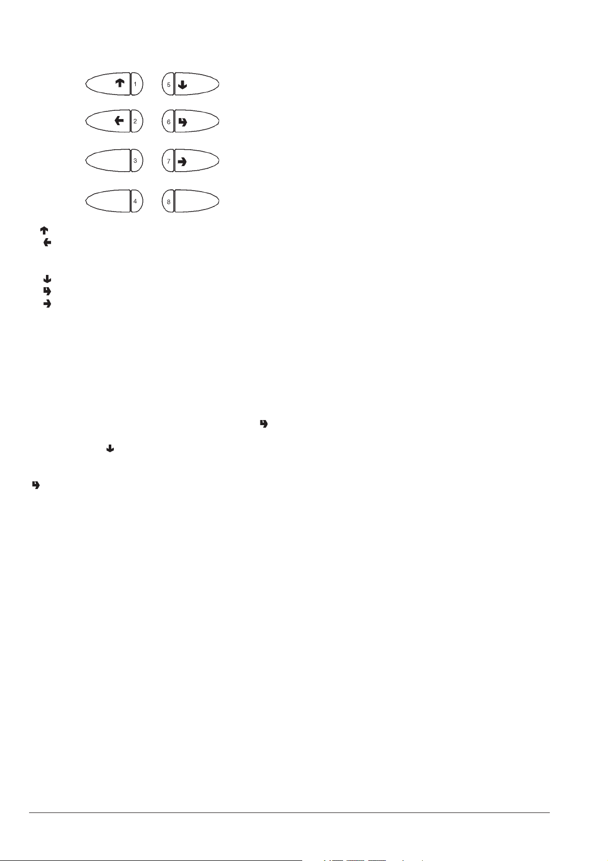
When in “programming” mode the selection buttons have the
following functions:
1 - Previous function / Increase data item (+1)
2 - Exit function / Cancel change
3 - Machine installation
4 5 - Next function / Decrease data item (- 1)
6 - Confirm function / confirm data
7 - Change data item
8 - Reset failures
The buttons preceded by the symbol allow scrolling through
the menu or changing of data; the other buttons are used
directly for that function.
DISPLAYING THE EXISTING FAILURES
When the “Present failures” function from the “programming” menu is displayed, press the confirm button “ ” to
display the error code of the current failure; then keep
pressing button “ ” to display the error code of the next
present failure.
If no failures are present, when pressing the confirm button
“ ” the message “No Failure” is displayed.
The possible failures are indicated in the following cases:
AIR-BREAK FAILURE
The machine will lock if after dispensing water corresponding to 150 pulses of the volumetric counter the microswitch
has not signalled the lack of water.
BOILER FAILURE
The machine will lock if after 10 minutes of heating from the
machine start, or from the last selection, the boiler fails to
reach the operating temperature.
COIN MECHANISM FAILURE
The machine will lock if it receives an impulse longer than
2 seconds on a validator line or there is no communication
with the serial coin mechanism for more than 30 seconds.
RAM DATA FAILURE
The data contained in the EEprom (i.e. the chip that stores
the setting variations) is wrong and must be retrieved from
the Eprom, thus losing all statistics information.
The message “INITIALISE” will start blinking on the display.
WATER FAILURE
The machine locks if the water level in the tank falls to less
than approximately 300 cc.
CUP FAILURE
When the empty cup column microswitch opens, the
column shift motor is activated. If after one full turn of the
cup dispenser the microswitch is not closed the message
“No cups” is displayed and the machine locks.
WATER LEAK FAILURE
If water is requested by the air-break without having been
used (selections, cleaning etc.) the machine will block
further water requests.
ROTOR FAILURE
Failed computation of the volumetric counter within a max.
given time.
COFFEE UNIT FAILURE
This failure is due to a mechanical lock of the unit or when
the unit is not present. The machine is not locked, but all
coffee-based selections are disabled.
COFFEE FAILURE
If after a period of 15 seconds of grinding coffee a dose is
not obtained, all coffee-based selections are disabled.
COFFEE RELEASE FAILURE
If after releasing the ground coffee dose the microswitch of
the coffee doser unit indicates the presence of coffee in the
doser chamber, all coffee based selections are disabled.
CUP RELEASE FAILURE
If after releasing one cup the positioning microswitch is not
triggered the control software disconnects power from the
release motor and the machine locks.
LIQUID WASTE FULL
If the machine is equipped with a liquid waste container
(housed in the cabinet) fitted with an overflow warning
device, the machine locks.
CHANGER FAILURE
The change-giver coin mechanism is not working or does
not communicate.
BILL VALIDATOR FAILURE
The bill accepter is not working or does not communicate.
CASHLESS FAILURE
The key device or the magnetic card is not working or does
not communicate.
© by NECTA VENDING SOLUTIONS SpA 03-2003 217 00
18
Page 23

PROGRAMMING THE
WATER AND POWDER DOSES
PROGRAMMING THE BASIC COIN AND
THE DECIMAL POINT
When either the “Wat. dose sett.” or the “Powd. dose sett.”
functions from the “programming” menu are displayed the
related doses can be varied.
The various doses are identified by dose codes, which are
displayed each time.
The dose code locates the water and powder doses related
to a given selection; any changes to one selection dose
also affects the compound selections where the dose code
is used.
Refer to the selection dose table for the dose code list.
The values of the doses displayed are expressed in:
- tenths of a second for powders;
- number of pulses of the volumetric counter for water.
Press the confirm button “ ” from the “programming” menu
to access the dose code list, which can be scrolled with the
“ ” and “ ” buttons.
When pressing correction button “ ”, this value will start
blinking and can be modified as necessary.
PRICE SETTING
When the “Price sett.” (price programming) function from
the “programming” menu is displayed, the 8 sales prices
stored can be changed.
The prices are indicated as number of basic coins.
Press the confirm button “ ” from the “programming” menu
to access the price list, which can be scrolled with the “ ”
and “ ” buttons. When pressing correction button “ ”, this
value will start blinking and can be modified as necessary.
PROGRAMMING THE PRICES
AND THE BUTTON STATUS
When the “Set Price/Button” (price setting) function of the
“programming” menu is displayed, the combination of the
button to one of the stored prices and/or to the status of a
selection can be changed.
Press the confirm button “ ” from the “programming” menu
to access the price list, which can be scrolled with the “ ”
and “ ” buttons. When pressing the correction button “ ”,
the selection status starts blinking. Using the “ ” and “ ”
buttons, the selection status can be changed from (enabled) to (disabled).
Press again the confirm button “ ” to display the price
number referred to in the price table.
When pressing correction button “ ”, this value will start
blinking and can be modified as necessary.
The buttons which control pre-selections do not need
combination with prices. In any case prices have no effect
on the pre-selection buttons.
When the “Basic coin / DP” (basic coin value) function from
the “programming” menu is displayed, the value of the
basic coin as well as the position of the decimal point can
be modified.
Press the confirm button “ ” from the “programming” menu
to display the current value of the basic coin.
Using the “ ” and “ ” buttons, the value of the basic coin
and the number of the decimal point position “dP” are
displayed alternately, i.e:
0 decimal point disabled
1 XXX.X
2 XX.XX
3 X.XXX
Press the correction button “ ”, these values will start
blinking and can then be modified as necessary.
PAYMENT SYSTEMS
When the “Payment system” function is displayed, it is
possible to define which payment system with MDB communication protocol to use, selecting among:
- Validator
- MDB
In order to install payment systems different from a validator
or cashless system, special kits must be used.
The payment systems must be housed in the cabinet.
PROGRAMMING THE VALIDATOR
If the payment system is a validator, it will be
necessary to define with which parameters to operate.
CREDIT CONTROL
It is possible to decide whether any excess credit paid is to
be cashed or made available to the user.
OPERATING VOLTAGE
According to the type of validator it is necessary to define
whether the
operating voltage is 12 V or 24 V.
VALIDATOR LINES
When the “Validat. Lines” (line setting) function is displayed, the value of the 6 validator coin lines can be
changed.
The value of the lines is indicated as number of basic coins.
Press the confirm button “ ” from the “programming” menu
to access the line list, which can be scrolled with the “ ” and
“ ” buttons.
When pressing correction button “ ”, this value will start
blinking and can be modified as necessary.
© by NECTA VENDING SOLUTIONS SpA 03-2003 217 00
19
Page 24

PROGRAMMING THE MDB DATA
INITIALISING
The menu of the MDB protocol has the following structure:
- Type of vending
- Change button
- Maximum credit
- Maximum change
- Accepted coins
- Not accepted coins
- Minimum level of tubes
- Dispensing buttons
- Accepted bills
TYPE OF VENDING
Setting the operating mode for multiple or single dispensing. With multiple dispensing, the change is not automatically returned after a successful selection, however the
credit is available for further selections. When pressing the
coin return button, the available credit is returned if its value
is lower than the maximum change value.
CHANGE BUTTON
It is used for enabling/disabling the change button, regardless of whether the selection was dispensed or not.
MAXIMUM CREDIT
This function is used to define the maximum accepted
credit.
MAXIMUM CHANGE
It is possible to set a limit to the total amount of change
returned by the coin mechanism when pressing the coin
return button or after a single dispensing serving.
Any credit exceeding the amount programmed with this
function will be cashed.
ACCEPTED COINS
It is possible to define which, among the coins recognised
by the validator, are to be accepted.
Check the label on the coin mechanism for the correct coin
to value matching, indicating the position of the coins.
DISPENSING COINS
This function programs the rejection of coins as change.
Check the label on the coin mechanism for the correct coin
to value matching, indicating the position of the coins.
MINIMUM LEVEL OF TUBES
It brings forward the “Insert exact amount” message for the
user, by adding a number of coins between 0 and 15 to the
programmed number of coins, to set the “full change tubes”
status.
DISPENSING BUTTONS
This function is used to enable or disable the buttons
on the coin mechanism to release the coins in the change
tubes.
ACCEPTED BILLS
It is possible to define which, among the bills recognised by
the validator, are to be accepted.
When the “Initialise” function is displayed the vending
machine can be initialised restoring all default data.
This function should be used if there is a memory data error
or when the EPROM is replaced.
All statistic information will be reset.
Press confirm button “ ” to display the message “Confirm?”. Press the button “ ” again to display the first
variable parameter to define the machine configuration.
The available options (blinking) can be scrolled with the “ ”
and “ ” buttons, the selection is confirmed with button “ ”
and the next parameter is presented. When pressing
button “ ” after the last parameter the display will show the
message “Working” for a few seconds and the machine is
set for the country use.
The parameters are as follows:
“Country” Type of doses to be
used for the selections
“Layout” Layout of containers and
selection menu from the
available ones
“Tank” Water supply from a tank in the
cabinet
SETTING THE MACHINE CODE
When the “Machine code” function is displayed the identification code number of the machine can be changed (from
the default 0000 to 9999).
Press the confirm button “ ” and the current code number
is displayed; then press the correction button “ ” and the
first digit will start blinking.
The value of the blinking digit can be increased or decreased with the “ ” and “ ” buttons.
When pressing the confirm button “ ”, the blinking digit will
take on the displayed value and the next digit starts
blinking.
© by NECTA VENDING SOLUTIONS SpA 03-2003 217 00
20
Page 25
MACHINE CONFIGURATION
SETTING THE PROMOTIONAL MESSAGE
When the “Machine Config.” function is displayed, the
machine configuration can be changed, and namely:
- cup dispensing / without cup
- with tank in the cabinet / from the mains
- presence of warning device for full liquid waste container (inside cabinet)
Press the confirm button “ ” to display the current status;
when pressing the correction button “ ” the status starts
blinking and can be changed with the “ ” and “ ” buttons.
IMPORTANT NOTICE!!!
When the machine is initialised, the configuration will
be assigned the default values “with cup /with tank /
with full waste container warning device”.
THEREFORE, AFTER INITIALISING THE MACHINE
MUST BE RECONFIGURED.
OPERATION COUNTER
This function is used to lock the machine after a preset
number of coffee selections, and a preset number of
instant selections.
Since this is a control tool used only by the vending
operator, a 4-digit password must be entered.
After entering the password, it is possible to set the number
of selections after which the machine locks, read the
number of selections already made and reset the lock
counter.
N.B.: The counters are set to zero by default;
With the counters set to zero, this function is disabled.
When this menu is displayed, press the confirm button “ ”
to display whether or not the message is enabled (ON/
OFF).
If the message is enabled, when pressing the confirm
button “ ” the first character will start blinking and can be
changed.
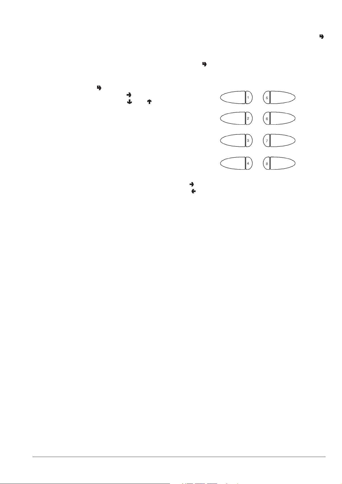
The buttons will take on the following functions:
1 - Next character
2 - Previous character
3 - Upper case/lower case
4 - ABCDEFGHI
5 - JKLMNOPQR
6 - STUVWXYZ
7 - 0123456789:;<=>?
8 - !"$%&'( )*+,-./
The message is stored by pressing button “2” when on the
last position.
LANGUAGE SELECTION
This function is used to select the language to be used for
displaying the messages.
The available languages are:
- English
- Italian
- French
- Spanish
- Portoguese
- German
© by NECTA VENDING SOLUTIONS SpA 03-2003 217 00
21
Page 26

WHIPPING TIME
This function is used to define how long (in tenths of a
second) instant drinks are to be whipped according to the
amount to be obtained.
PROGRAMMING ACCESS PASSWORD
DIRECT FUNCTIONS
INSTALLATION
Press the installation button “3” to carry out the hydraulic
system filling operations, even with the air-break full.
This function is used to enable the request for a password
to access the programming procedures.
The password is the button sequence 1 1 2 2 and cannot
be changed.
SELECTION CONFIGURATION
This function is used to determine, as an exception to the
machine configuration, which accessories should or should
not be dispensed for a specific selection.
The following is possible for each selection button (1 to 8,
excluding the pre-selection buttons):
- not dispense the cup (if the machine configuration
includes the cup, but not vice versa);
- not dispense the stirrer if the selection is unsweetened;
- not dispense sugar and stirrer for selections which are
defined as sweetened (but not dispense sugar for
selections which are defined as unsweetened).
The settings defined with the selection configuration are
used also for complete test selections.
DISCOUNT DATA
This function is used to determine by how much to increase
or decrease the price for a selection when using a ceramic
cup.
With the value set to 0 the function is disabled.
RESET FAILURES
Press the failure reset button “8”; the message “Running”
is displayed for a few seconds and all present failures are
reset.
SPECIAL SALES
This function is used to enable or disable Free Vend and to
set the number of consecutive instant drinks (1 to 9; 5 by
default) that are dispensed when the “Jug facilities” function is enabled.
After these functions are enabled, do as follows:
- while in normal operating mode, press button “8” for a
few seconds;
- enter the password that was just set;
- make a selection within 10 seconds.
© by NECTA VENDING SOLUTIONS SpA 03-2003 217 00
22
Page 27
Chapter 3
MAINTENANCE
Important notice!!
Access to the machine interior for maintenance and/or
repairs is via the back panel.
Therefore the machine is designed to be rotated, thus
allowing removal of the back panel.
The integrity of the machine and compliance with the
standards of the relevant systems must be checked at
least once a year by qualified personnel.
Before starting any maintenance operations requiring
parts of the unit to be removed, the machine must
always be switched off.
The operations described below must be carried out
only by personnel who have the specific knowledge of
the machine functioning from a point of view of electrical safety and health regulations.
INTRODUCTION
To ensure correct operation for a long period, the machine
must be subjected to regular maintenance.
The following sections contain the procedures and the
maintenance schedule, which are only a general indication, as they greatly depend on the operating conditions
(e.g. water hardness, environmental humidity and temperature, type of product used, etc.).
The procedures described in this chapter are not exhaustive of all maintenance operations to be carried out.
More complex operations (e.g. boiler descaling) should be
carried out by qualified technicians only having specific
knowledge of the machine.
To prevent oxidation or the action of chemical agents, the
stainless steel and varnished surfaces should be kept
clean by using mild detergents (solvents must not be
used).
Never use water jets to clean the machine.
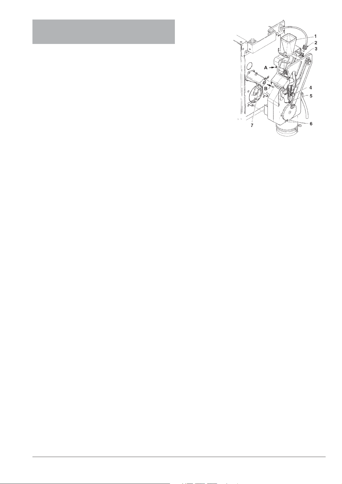
BREWING UNIT MAINTENANCE
Every 10,000 selections or every 6 months some maintenance of the coffee unit must be carried out.
Maintenance is carried out as follows:
- remove the boiler teflon hose connection from the upper
piston, paying attention not to lose the seal (see Fig. 16);
- undo the knob securing the unit to the bracket;
Fig. 16
1 - Coffee funnel
2 - Boiler connecting hose
3 - Unit securing knob
4 - Upper piston snap ring
5 - Lower piston snap ring
6 - Reference notches
7 - Ratiomotor handle pin
Removing the upper filter
- Take the snap ring out of its seat;
- remove the piston from the crosspiece;
- remove the filter and the piston seal.
Removing the lower filter
- Loosen screws A and B enough to release the coffee
funnel (see fig. 16);
- remove the lower piston snap ring;
- take the piston out of brew chamber and remove the filter.
Soak all components removed from the unit in a solution of
boiling hot water and coffee machine detergent for approx.
20 minutes.
Thoroughly rinse and dry all parts, then reinstall them in the
reverse order of disassembly, taking particular care that:
- the piston is positioned in the correct notch for the coffee
dose used (see relevant section);
- the two reference notches match and that the coffee unit
is inserted.
Important notice!!!
Check that the handle pin of the ratiomotor is correctly
engaged in its seat.
- remove the brewing unit.
© by NECTA VENDING SOLUTIONS SpA 03-2003 217 00
23
Page 28
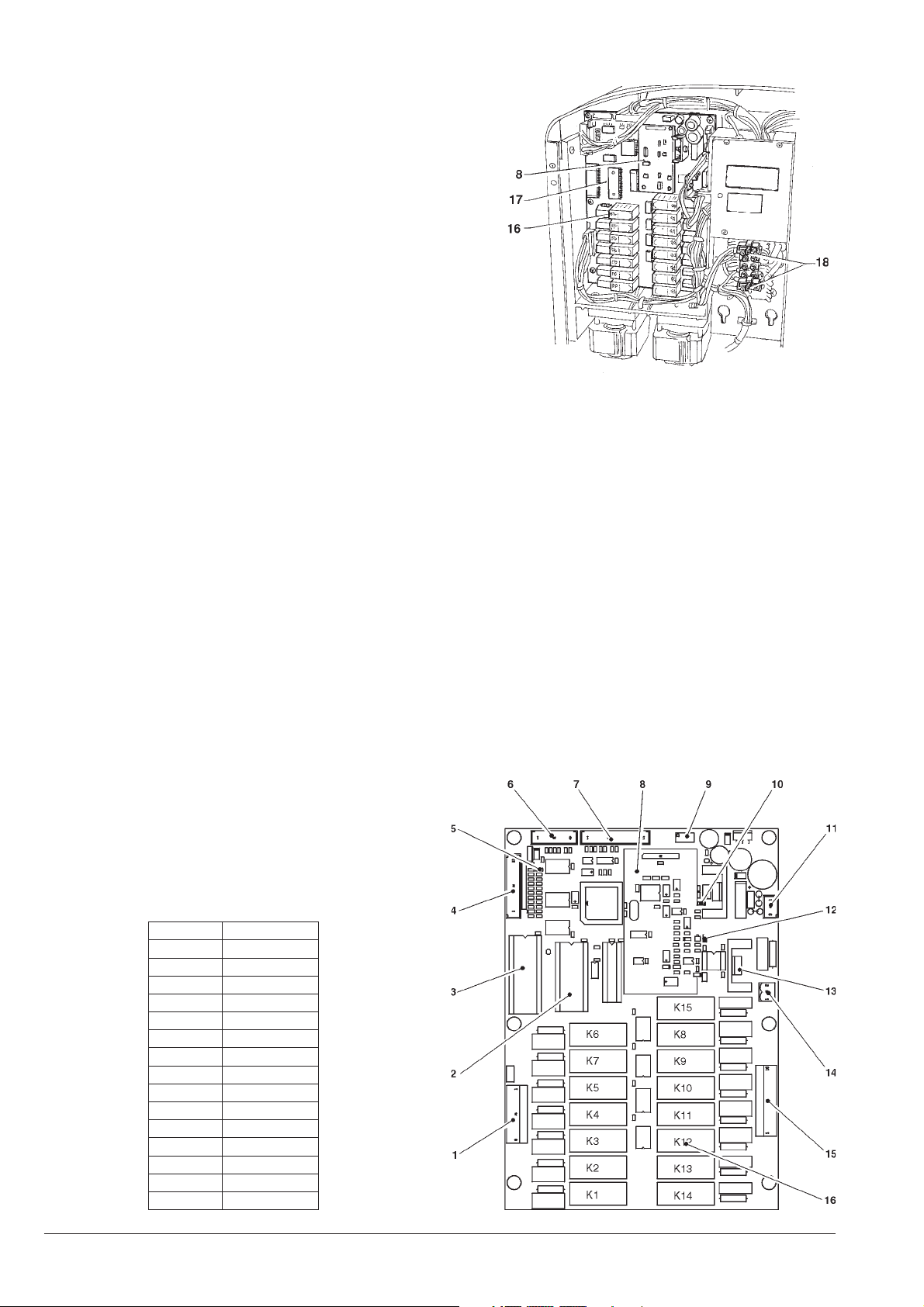
ANNUAL SANITISING
At least once a year, or more frequently according to the
use of the machine and the quality of the inlet water, the
entire foodstuff circuit system must be cleaned and sanitized in the following way:
- all parts of the hydraulic system in contact with food, must
be removed from the unit and fully disassembled;
- wash all parts with detergent being sure that all visible
residue and product layers are mechanically removed,
using a brush if necessary;
- all components must be soaked in a sanitising solution for
at least 20 minutes;
- the unit internal surfaces are to be cleaned with the same
sanitising solution;
- thoroughly rinse and then reinstall the parts.
Before restarting the machine, the same sanitising
procedure described in section “Sanitising the foodstuff circuits and the mixers” should be repeated.
Fig.17
PRINTED BOARD FUNCTIONS
AND INDICATOR LIGHTS
CONTROL BOARD
This board, placed at the back of the machine, (see Fig. 17)
processes the information from the push-buttons and from
the payment system; it also controls the actuations and the
push-button board.
The 15 V AC voltage required for board operation is
supplied by a transformer which is protected by a 125 mAT
fuse on the primary and by a 1.25 AT fuse on the secondary
winding. The voltage supply is rectified and stabilised
directly by the board.
The board also houses the EPROM (see Fig. 17 - 3).
- the yellow LED indicates the presence of 12 V DC;
- the green LED blinking indicates that the microprocessor
is working correctly;
- the red LED indicates the operating status of the boiler
heating element.
1 - 230 V~ users
2 - RAM
3 - EPROM
4 - Input signal
5 - Green LED
6 - Not used
7 - To the push-button board
8 - Expansion board for payment systems (optional)
9 - Boiler temperature trimmer
10 - Green LED
11 - Board power supply
12 - Red LED
13 - Boiler heating element TRIAC
14 - To boiler heating element
15 - 230 V~ users
16 - Relays K1÷K15
17 - C.P.U. board
18 - Transformer fuses
SIALEROSSERPSE
1K
2K
3K
4K
5K
6K
7K
8K
9K
01K
11K
21K
31K
41K
51K
© by NECTA VENDING SOLUTIONS SpA
RE
CSE
CAM
MP
M
2E
1E
1FM
ZDM
2DM
1DM
)AEE(MP
BCSM
BSM
PSM
24
03-2003 217 00
Page 29
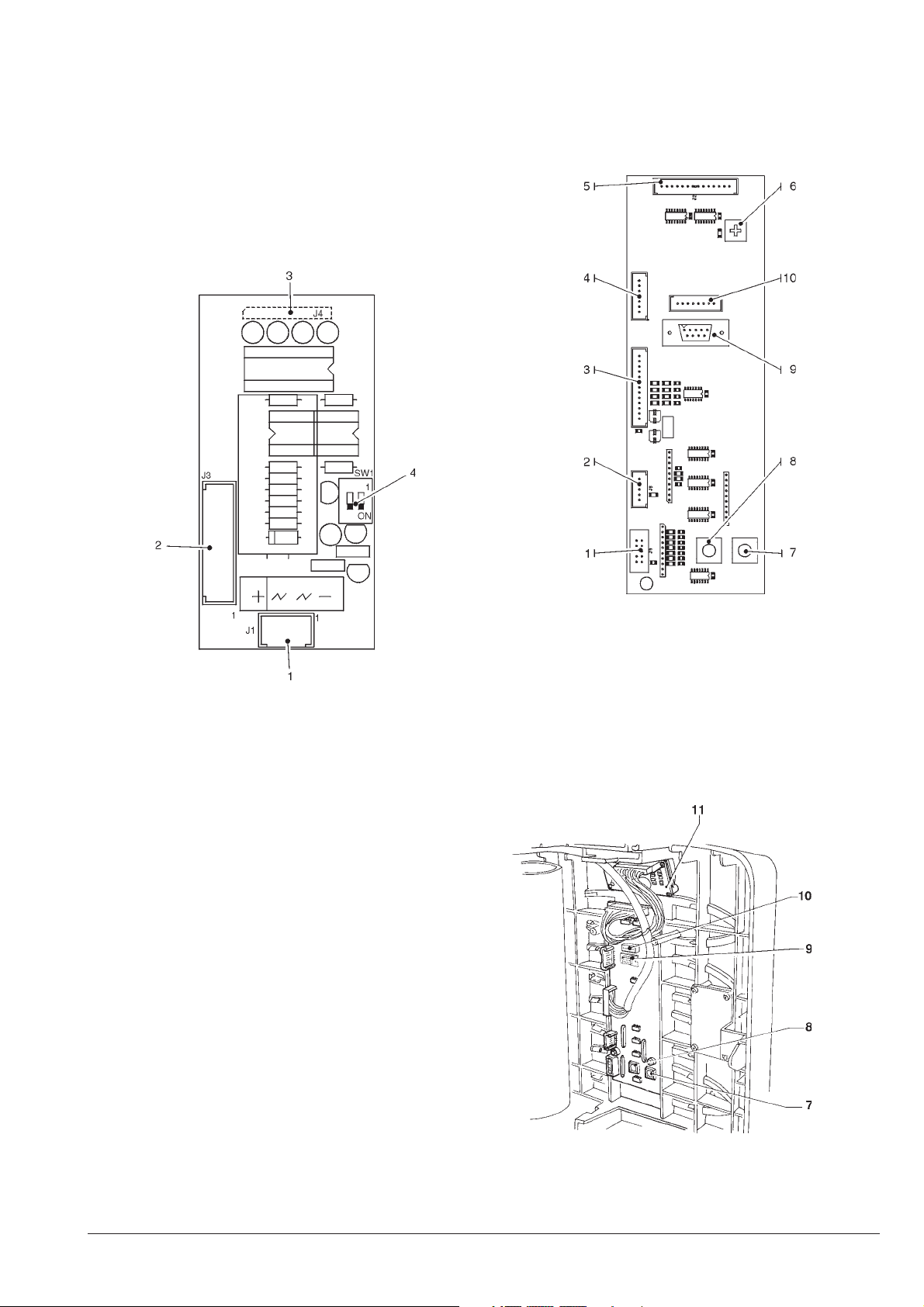
PAYMENT SYSTEMS
EXPANSION BOARD
This board is located above the control board and controls
the payment systems.
According to the communication protocol used by the
payment system, the 2 minidips will have to be set to ON
(MDB).
PUSH-BUTTON BOARD
This board controls the alphanumeric display, the selection buttons and the programming button (see Fig 19).
It supports the coin mechanism connectors as well as the
printer port.
Fig. 18
1 - Power supply (MDB BDV)
2 - To the payment system (with specific cable)
3 - To the control board
4 - Payment system configuration minidips
OFF = Executive/BDV
ON = MDB
Fig. 19
1 - To the front validator
2 - Not used
3 - To the machine board
4 - Signals: free vend - jug facilities
5 - To the display board
6 - Display contrast adjusting trimmer
7 - Programming button
8 - Cleaning button
9 - RS232 port
10 - To the programmer
11 - Display board
© by NECTA VENDING SOLUTIONS SpA 03-2003 217 00
25
Page 30
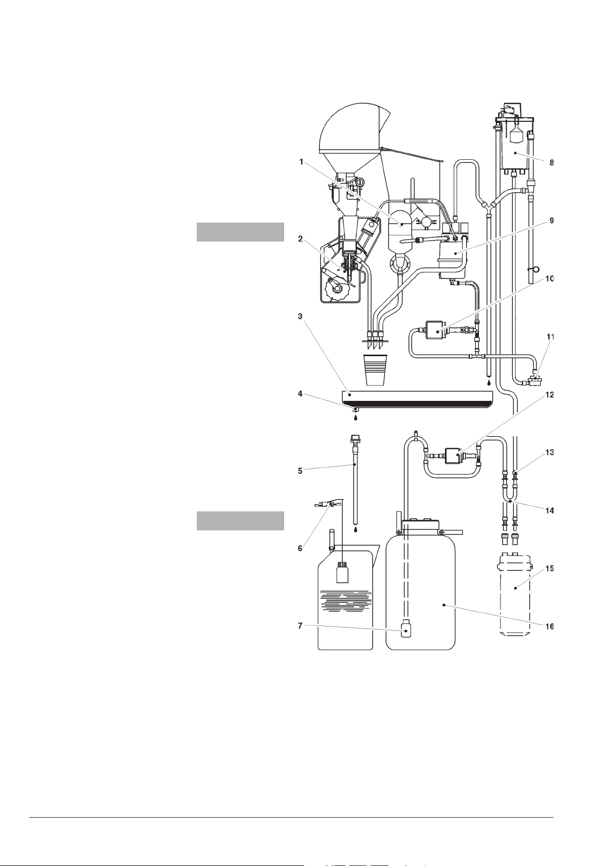
HYDRAULIC SYSTEM
1 - Mixer
2 - Coffee unit
3 - Dispensing compartment drip tray
4 - Drip tray drain boss
5 - Drain pipe
6 - Liquid waste container float
7 - Non-return valve
8 - Air-break
9 - Boiler
10 - Coffee brewer pump
11 -Volumetric counter
12 - Water supply pump
13 - Water supply hose fitting
14 -Softener cartridge bracket
15 -Softener cartridge (optional)
16 - Drinking water tank
Machine
Cabinet
© by NECTA VENDING SOLUTIONS SpA
26
03-2003 217 00
Page 31
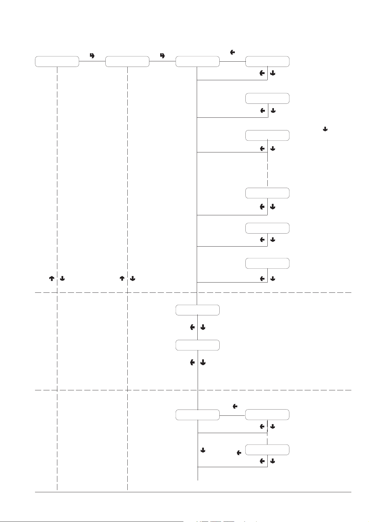
Maintenance menu
Statistics Display Statistics Statistic N. 1 Sel.N.1 P=xxxx
P = Paid dispensing
Sel.N.1 G= xxxx
G = Free dispensing
Sel.N.1 T= xxxx
T = Test dispensing
Sel.N. 8 P=xxxx
Sel.N. 8 G= xxxx
READING DATA
DISPENSING BY
SELECTION
Press button " " to
display statistics for each
selection (1 - 8)
Tot. cup = xxxx
No cup = xxxx
Statistic N. 2
Sel.N. 8 T= xxxx
Total dispensing with cup
Total dispensing with ceramic
cup in normal vending mode
DISPENSING BY PRICE
Pr. sel. 1 XXXX
© by NECTA VENDING SOLUTIONS SpA
27
Pr. sel. 8 XXXX
03-2003 217 00
Page 32
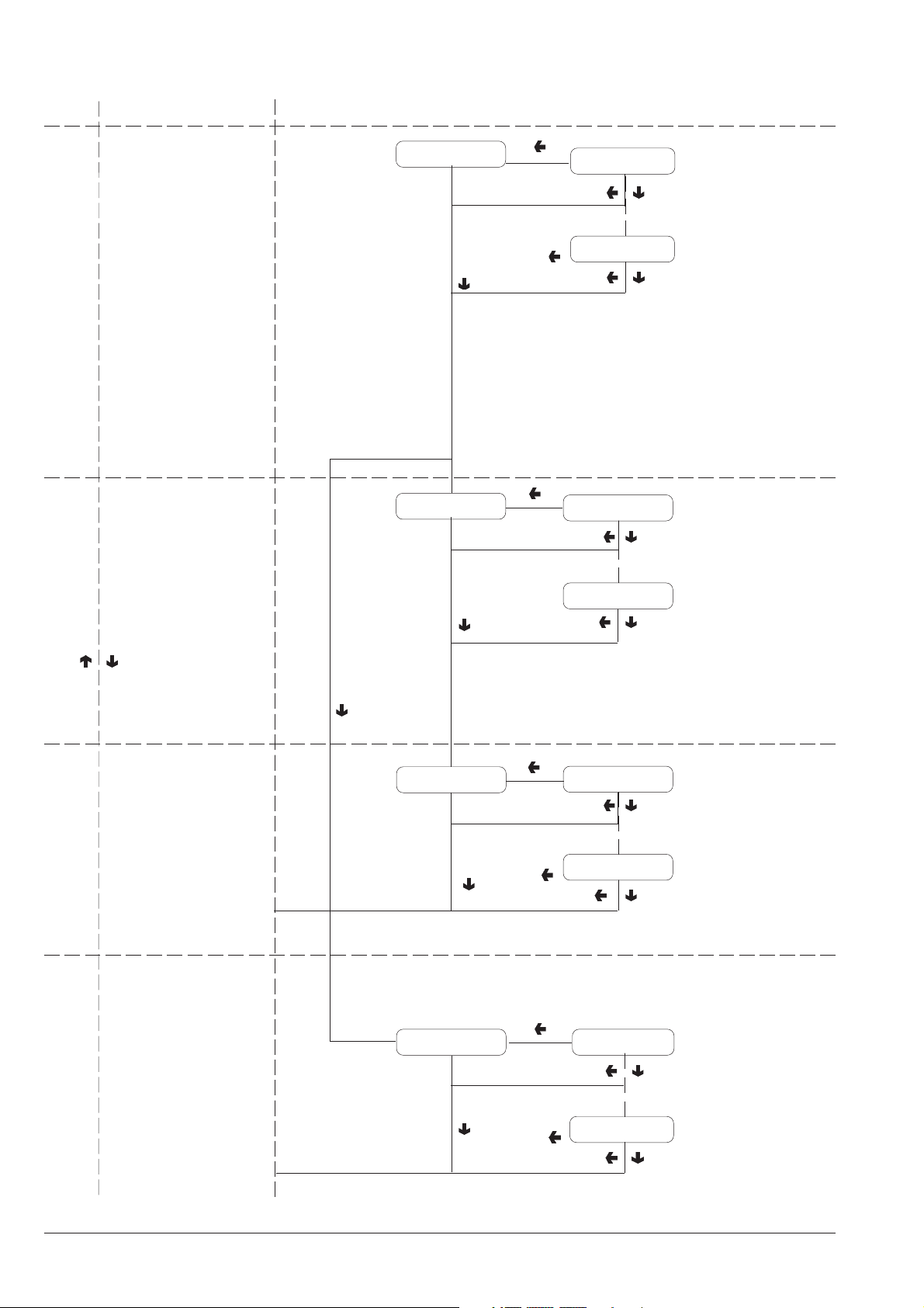
Maintenance menu
USING A VALIDATOR
TOTALIZER
OR
Statistic N. 3
Statistic N. 4
Failure 1 = XX
Failure 16 = XX
Coin 1 = XXXX
FAILURE COUNTER
LIST OF FAILURES
N. 1 - Air-break
N. 2 - Boiler
N. 3 - Coin mechanism
N. 4 - RAM data
N. 5 - Water failure
N. 6 - Cup failure
N. 7 - Water leak
N. 8 - Volumetric counter
N. 9 - Coffee unit
N. 10 - Coffee failure
N. 11 - Coffee release
N. 12 - Cup release
N. 13 - Liquid waste full
N. 14 - Changer
N. 15 - Bill validator
N. 16 - Cashless
CASHED BY COINS
USING AN MDB
PAYMENT SYSTEM
Statistic N. 5
Cashed with coins
Total credit
Coin 6 = XXXX
Tot 1 = XXXX
Tot 2 = XXXX
Audit 1 = XXXXStatistic N. 4
Audit 11 = XXXX
TOTAL CASHED
MDB STATISTICS
Aud. 1 Money in the tubes
Aud. 2 Money to the tubes
Aud. 3 Money to the box
Aud. 4 Change return
Aud. 5 Excess
Aud. 6 Releasing tubes
Aud. 7 Loading tubes
Aud. 8 Cash sales
Aud. 9 Cashed bills
Aud. 10 Charge key
Aud. 11 Sales with key
© by NECTA VENDING SOLUTIONS SpA
28
03-2003 217 00
Page 33
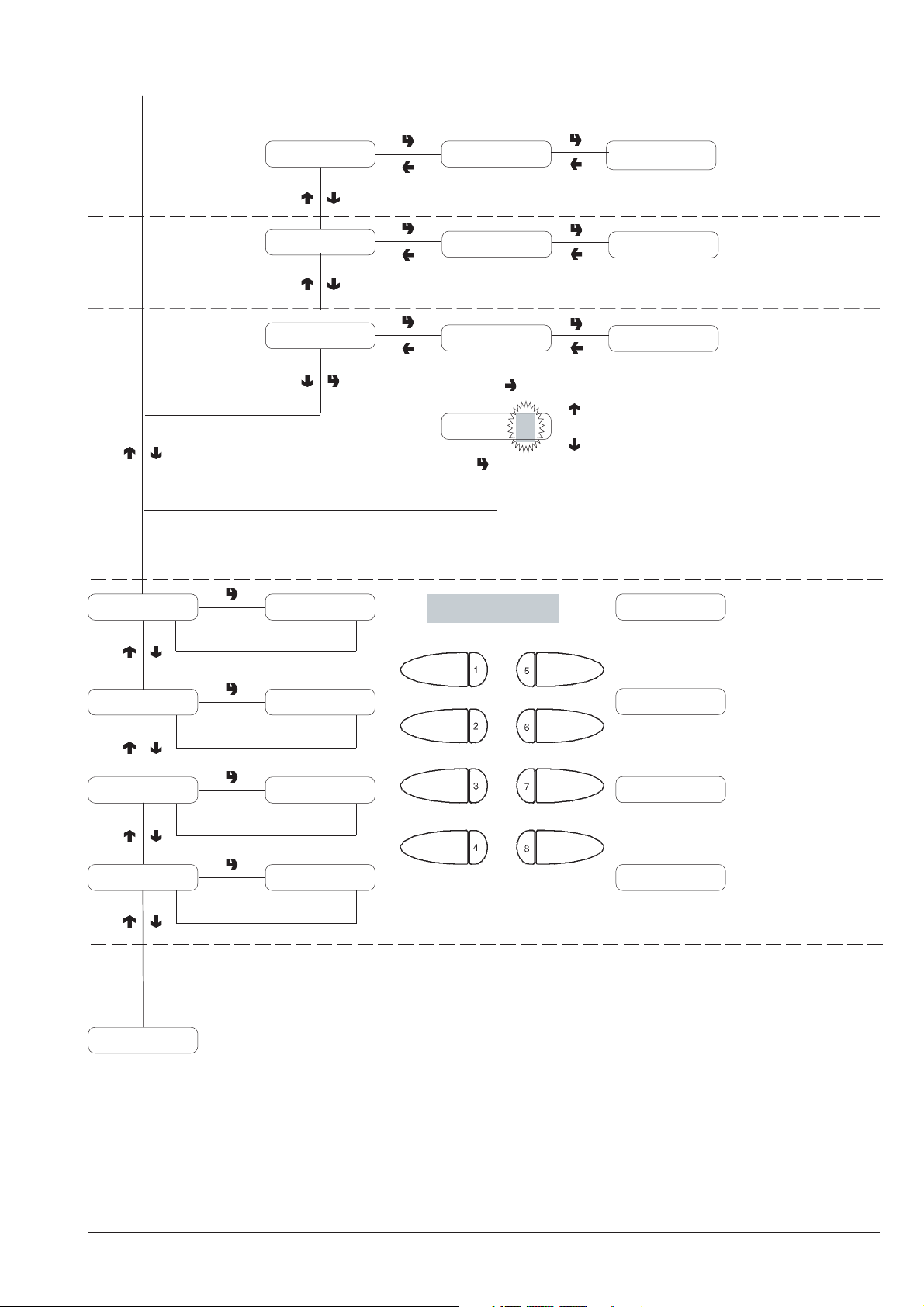
Maintenance menu
Print statistics
Delete data
Counter
Confirm?
Confirm?
Counter ON
Counter
ON
Counter = ####
ON
OFF
Working
Working
Confirming with the printer
connected, print all
statistics as displayed
After a few seconds all
data is reset, with the
exception of the general
counter
Reading counters
If ON, the counters are
displayed at machine start.
Complete sel. Selection
4 Sec
Powder only Selection
4 Sec
Water only Selection
4 Sec
No accessories Selection
4 Sec
Special functions
Menu
Dispensing
Dispensing
Dispensing
Dispensing
TEST DISPENSING
© by NECTA VENDING SOLUTIONS SpA
29
03-2003 217 00
Page 34
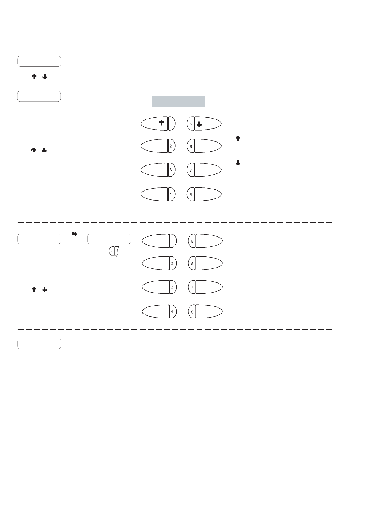
Maintenance menu
No accessories
Special functions
Key 2
1 - Previous function
2 - Grind and release a coffee dose
3 - Dispense sugar
4 - Autotest
5 - Next function
6 - Rotate coffee unit
7 - Release cup
8 - Empty air-break
Fill tubes Credit: XXXX
Statistics
TUBES CONTROL
1 - Release tube "A"
2 - Release tube "B"
3 - Release tube "C"
4 - Release tube "D"
5 6 7 8 - Exit function
© by NECTA VENDING SOLUTIONS SpA
30
03-2003 217 00
Page 35
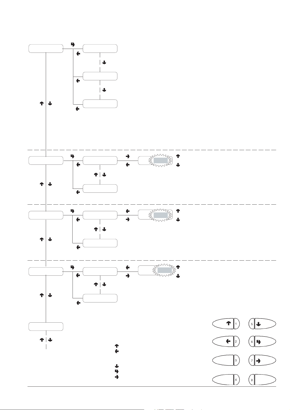
Programming menu
Failure list Air-Break failure
Boiler failure
xxxxxxxx
Water doses
Z1 XXXX
I3
Z1
XXXX
XXXX + 1
XXXX - 1
DISPLAY PRESENT
FAILURES
LIST OF FAILURES
N. 1 - Air-break
N. 2 - Boiler
N. 3 - Coin mechanism
N. 4 - RAM data
N. 5 - Water failure
N. 6 - Cup failure
N. 7 - Water leak
N. 8 - Volumetric counter
N. 9 - Coffee unit
N. 10 - Coffee failure
N. 11 - Coffee release
N. 12 - Cup release
N. 13 - Liquid waste full
N. 14 - Changer
N. 15 - Bill validator
N. 16 - Cashless
WATER DOSES
Refer to the selection dose
table for the correspondence
between dose code and
water dose
Powder doses
Set Prices
Set Prices/Buttons
© by NECTA VENDING SOLUTIONS SpA
Z1 XXXX
I3
Price N.1XXXX
Price N. 8
Z1
Price N.1
1 - Previous function / Increase data item (+1)
2 - Exit function / Cancel change
3 - Machine installation
4 -
5 - Next function / Decrease data item (- 1)
6 - Confirm function / confirm data
7 - Change data item
8 - Reset failures
XXXX
XXXX
XXXX + 1
XXXX - 1
XXXX + 1
XXXX - 1
31
POWDER DOSES
Refer to the selection dose
table for the correspondence
between dose code and
powder dose
PRICE VALUE
0012 Colibrì
Page 36
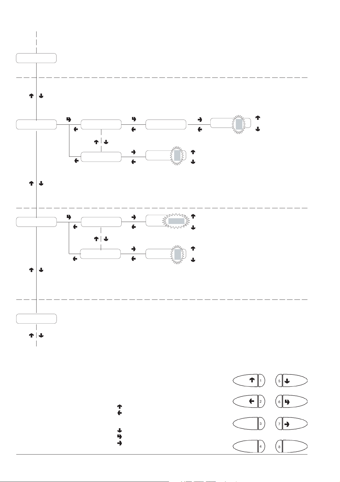
Programming menu
Set Prices
PRICE VALUE AND
STATUS
BUTTON
Previous price
Set Prices/Buttons Button 1= ON
Basic unit/dP Basic unit XXXX
Button 1 = ON
Button 8 =ON
Dec. point: X
Button 8 =
Basic unit
Dec. point
XXXX
ON
X + 1
X - 1
Next price
Enable Button
ON
Disable Button
OFF
XXX + 1
Price N.
X
BASIC COIN VALUE AND
XXX - 1
X
X + 1
X - 1
DECIMAL
0 to 3
POINT POSITION
Payment systems
© by NECTA VENDING SOLUTIONS SpA
1 - Previous function / Increase data item (+1)
2 - Exit function / Cancel change
3 - Machine installation
4 -
5 - Next function / Decrease data item (- 1)
6 - Confirm function / confirm data
7 - Change data item
8 - Reset failures
32
03-2003 217 00
Page 37
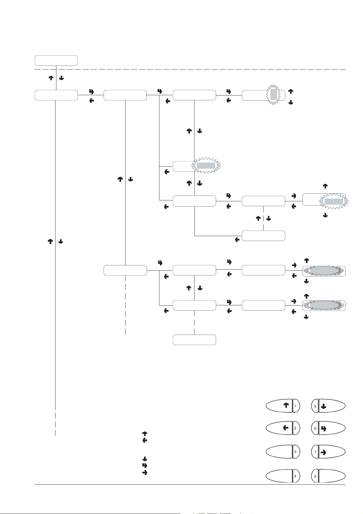
Programming menu
Basic unit/dP
VALIDATOR SETTING
Payment systems Validator
MDB
Credit
Power supply
Validator lines
12V
Credit
Line A XXXX
Line F XXXX
Typo of Vend Single Vend
ON
ON
OFF
Excess credit available
Power supply 12-24 V
Coin line value
A to F
Line A
MDB SETTING
XXX + 1
XXXX
XXX - 1
Single vend
Single Vend
© by NECTA VENDING SOLUTIONS SpA
Change button Enabled
Maximum credit
1 - Previous function / Increase data item (+1)
2 - Exit function / Cancel change
3 - Machine installation
4 -
5 - Next function / Decrease data item (- 1)
6 - Confirm function / confirm data
7 - Change data item
8 - Reset failures
33
Multi Vend
Enabled
Enabled
Disabled
03-2003 217 00
Page 38
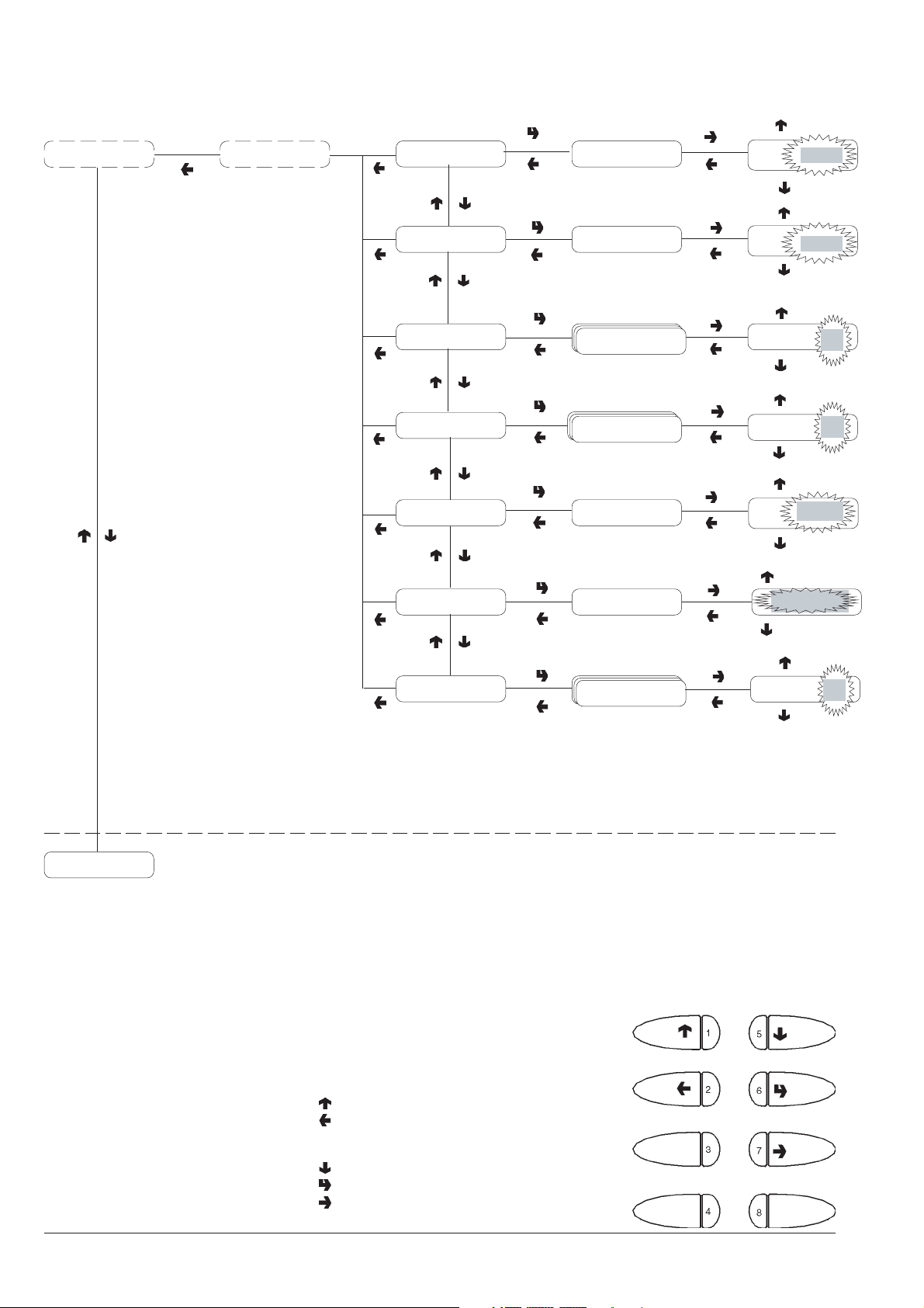
Programming menu
XXXX + 1
Payment systems MDB
Value = #####Maximum credit
Maximum change Value = #####
Accepted coins
Coin 1
Coins 1 to 16
Not accepted coins
Coin 1
Coins 1 to 16
Empty level Value = #####
Value 0 to 15
Dispensing buttons Enabled
Value =
Value =
Coin 1
Coin 1
Value =
XXXX
XXXX - 1
XXXX + 1
XXXX
XXXX - 1
Yes
Yes
No
Yes
Yes
No
XXXX + 1
XXXX
XXXX - 1
Enabled
Enabled
Initialising
Accepted bills
Bill 1
Bills 1 to 16
Disabled
Yes
Bill 1 Yes
No
© by NECTA VENDING SOLUTIONS SpA
1 - Previous function / Increase data item (+1)
2 - Exit function / Cancel change
3 - Machine installation
4 -
5 - Next function / Decrease data item (- 1)
6 - Confirm function / confirm data
7 - Change data item
8 - Reset failures
34
03-2003 217 00
Page 39
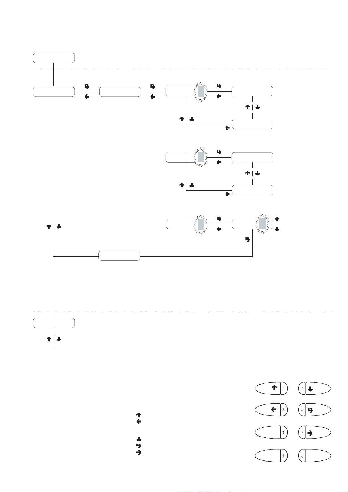
Programming menu
Payment systems
INITIALISING
Initialising Confirm?
Working
Country
Layout
Tank
Kor
ON
Country name
Type of doses for:
Korea
Country name
1
Layout 1
List of layouts available per
model/country.
See selection dose table
Layout n
Tank
ON
Tank ON / OFF
Machine code
© by NECTA VENDING SOLUTIONS SpA
1 - Previous function / Increase data item (+1)
2 - Exit function / Cancel change
3 - Machine installation
4 -
5 - Next function / Decrease data item (- 1)
6 - Confirm function / confirm data
7 - Change data item
8 - Reset failures
35
03-2003 217 00
Page 40
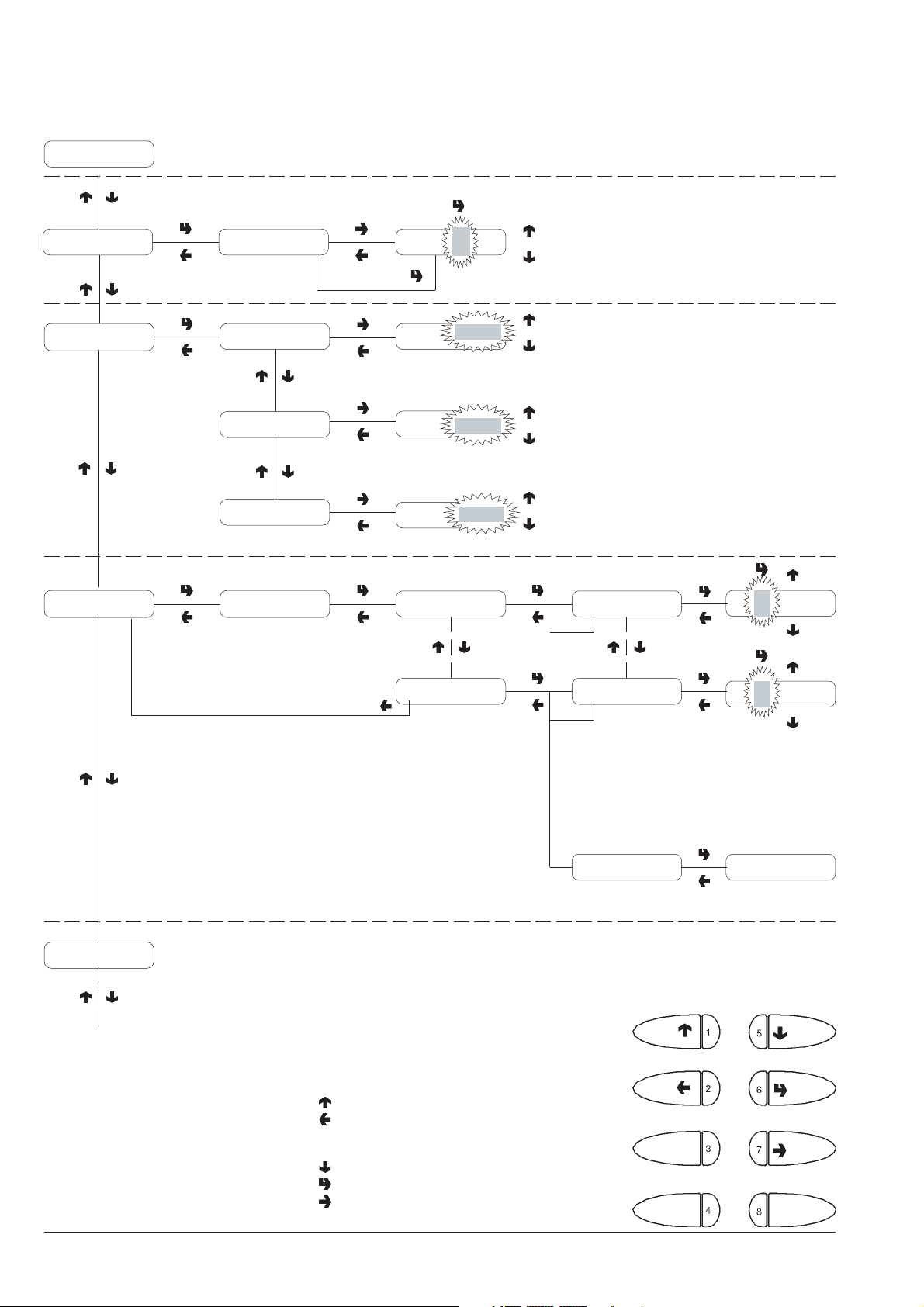
Programming menu
Initialising
Machine code
Machine Config.
Selection counter
Code = 0000 Code = 000
X
Cup release Cup
Tank
Equipped cabinet
Password ####
Tank
Cabinet
Espresso coffee
Instant
ON
ON
ON
X + 1
X - 1
ON
OFF
ON
OFF
ON
OFF
8
P =nnnn;A=nnnn
P =nnnn;A=nnnn
Machine identification code
Dispensing without cups
Water supply from the tank
in the cabinet
Warning device for full
liquid waste container in
the cabinet
X + 1
X
P = nnn;A=nnnn
X - 1
X + 1
X
P = nnn;A=nnnn
Prom. message
X - 1
Upon entering the 4th digit the
new value is confirmed
P = No. of programmed selections
A = No. of selections made
Cancel Confirm?
Reset counters of
selections made
1 - Previous function / Increase data item (+1)
2 - Exit function / Cancel change
3 - Machine installation
4 -
5 - Next function / Decrease data item (- 1)
6 - Confirm function / confirm data
7 - Change data item
8 - Reset failures
© by NECTA VENDING SOLUTIONS SpA
36
03-2003 217 00
Page 41
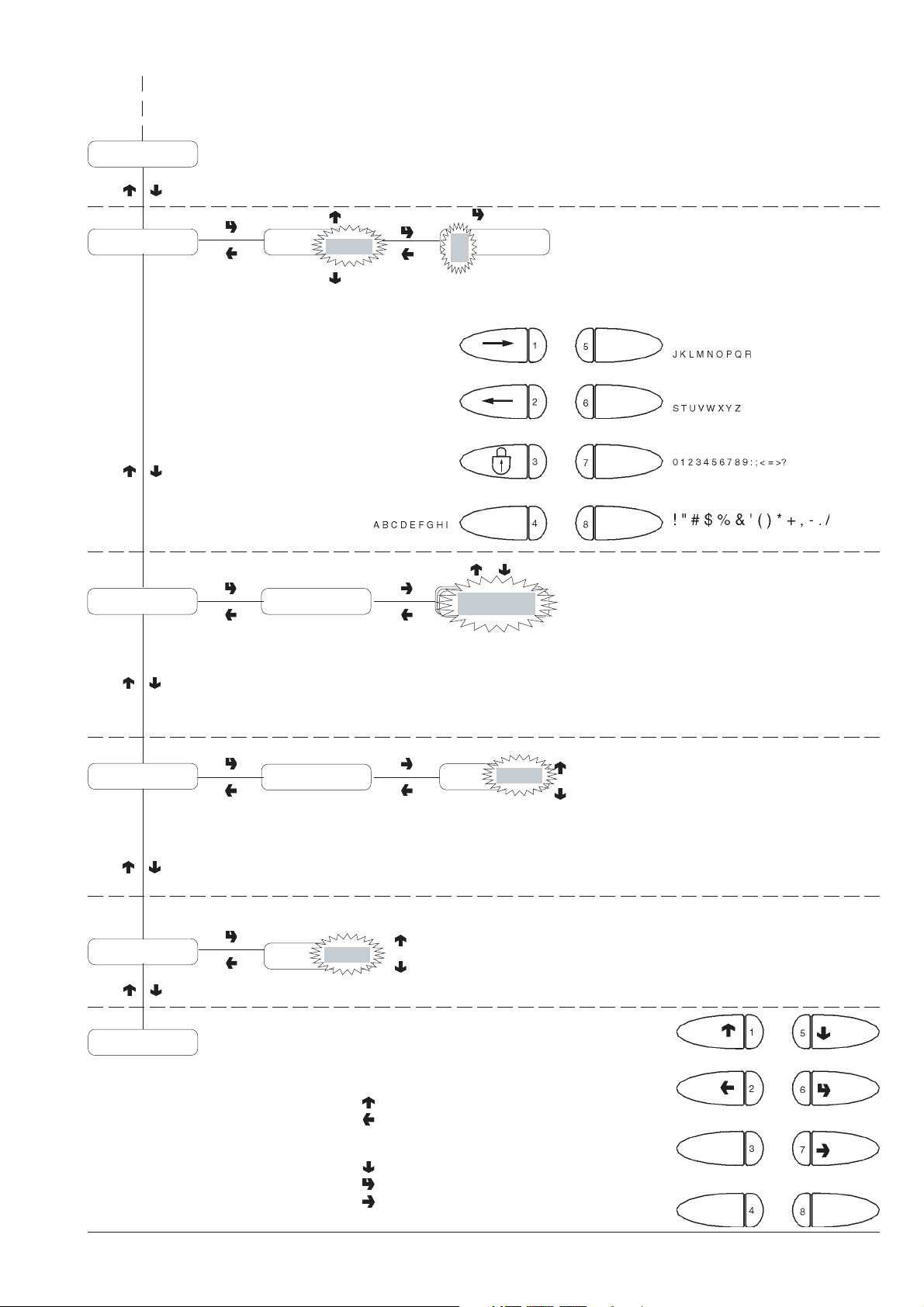
Programming menu
Selection counter
ON
Prom. message Message xxxxxxxxxxxx
ON
X
Language Language name
OFF
If the message is ON
Display messages in
available languages:
Language name
.English
.Italian
.French
.Spanish
.Portuguese
.German
Whipping time
Password
Selection Config.
© by NECTA VENDING SOLUTIONS SpA
Whipping t/s XXX
Password
ON
1 - Previous function / Increase data item (+1)
2 - Exit function / Cancel change
3 - Machine installation
4 -
5 - Next function / Decrease data item (- 1)
6 - Confirm function / confirm data
7 - Change data item
8 - Reset failures
ON
OFF
Whipping
XXXX
XXX + 1
XXX - 1
To access programming
37
03-2003 217 00
Page 42
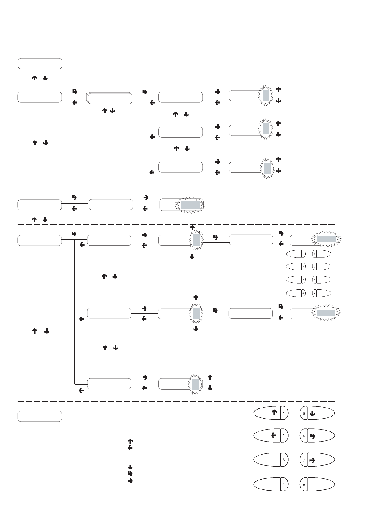
Programming menu
Password
Selection Config. Cup release ON
Button 1
Cup release
ON
ON
OFF
Enable
Disable
Dati sconto
Special sales
Buttons 1 to 8
Val = #####
Free Vend ON
Jug Facilities ON
Stirrer release ON
Sugar ON
Value =
XXXX
Free Vend
Jug Facilities
ON
ON
ON
OFF
ON
If ON
If ON
Stirrer release
Sugar
Password = XXXX
Password = XXXX
ON
ON
ON
OFF
ON
OFF
Enable
Disable
Enable
Disable
Password
Password
XXXX
XXXX
Present failures
© by NECTA VENDING SOLUTIONS SpA
Remaining sel. X Remaining sel.
1 - Previous function / Increase data item (+1)
2 - Exit function / Cancel change
3 - Machine installation
4 -
5 - Next function / Decrease data item (- 1)
6 - Confirm function / confirm data
7 - Change data item
8 - Reset failures
38
OFF
X + 1
X
X - 1
The data item has value
only if Jug Facilities is ON
03-2003 217 00
Page 43
WIRING DIAGRAM LEGEND
INITIALS DESCRIPTION
CM1 COFFEE UNIT MOTOR CAM
CMSB CUP RELEASE MOTOR CAM
CV VOLUMETRIC COUNTER
E1-... INSTANT SOLENOID VALVE
EEA WATER INLET SOLENOID VALVE
ER COFFEE DISPENSER SOLENOID VALVE
ESC COFFEE RELEASE MAGNET
EX EXECUTIVE COIN MECH CONNECTOR
FA RADIO INTERFERENCE SUPPRESSOR
ID COFFEE DOSE SWITCH
IDF DIFFERENTIAL SWITCH
IMSP STIRRER RELEASE MICRO-SWITCH
IP DOOR SWITCH
IPF WASTE CONTAINER OVERFLOW SWITCH
IVA EMPTY BOILER MICRO-SWITCH
IVB EMPTY CUP DISPENSER MICRO SWITCH
KC1-.. COFFEE BOILER CUTOUT
KS1-.. SAFETY CUTOUT
LCD LIQUID CRYSTAL DISPLAY
M COFFEE UNIT MOTOR
INITIALS DESCRIPTION
MAC GRINDER
MD1-.. INGREDIENT MOTOR - INSTANT
MDB CONNECTOR FOR MDB COIN MECHANI
MDZ INGREDIENT MOTOR - SUGAR
MF1-.. WHIPPER MOTORS
MSB CUP RELEASE MOTOR
MSCB CUP CONTAINER SHIFT MOTOR
MSP STIRRER RELEASE MOTOR
NTC TEMPERATURE PROBE
PM PUMP
RCC COFFEE BOILER HEATING ELEMENT
RIS COFFEE UNIT HEATER
RS232 SERIAL PORT
SM CONTROL BOARD
SP PUSH-BUTTON BOARD
TR TRANSFORMER
TR1 TRANSFORMER 230 V 24 V
TX.... DELAYED FUSE (X=COURRENT)
VAR VARISTOR
VENT FAN
© by NECTA VENDING SOLUTIONS SpA 03-2003 217 00
39
Page 44
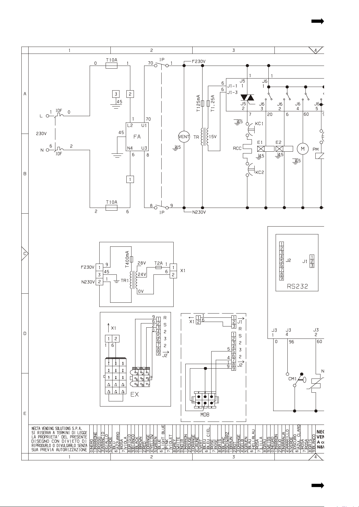
Page 45
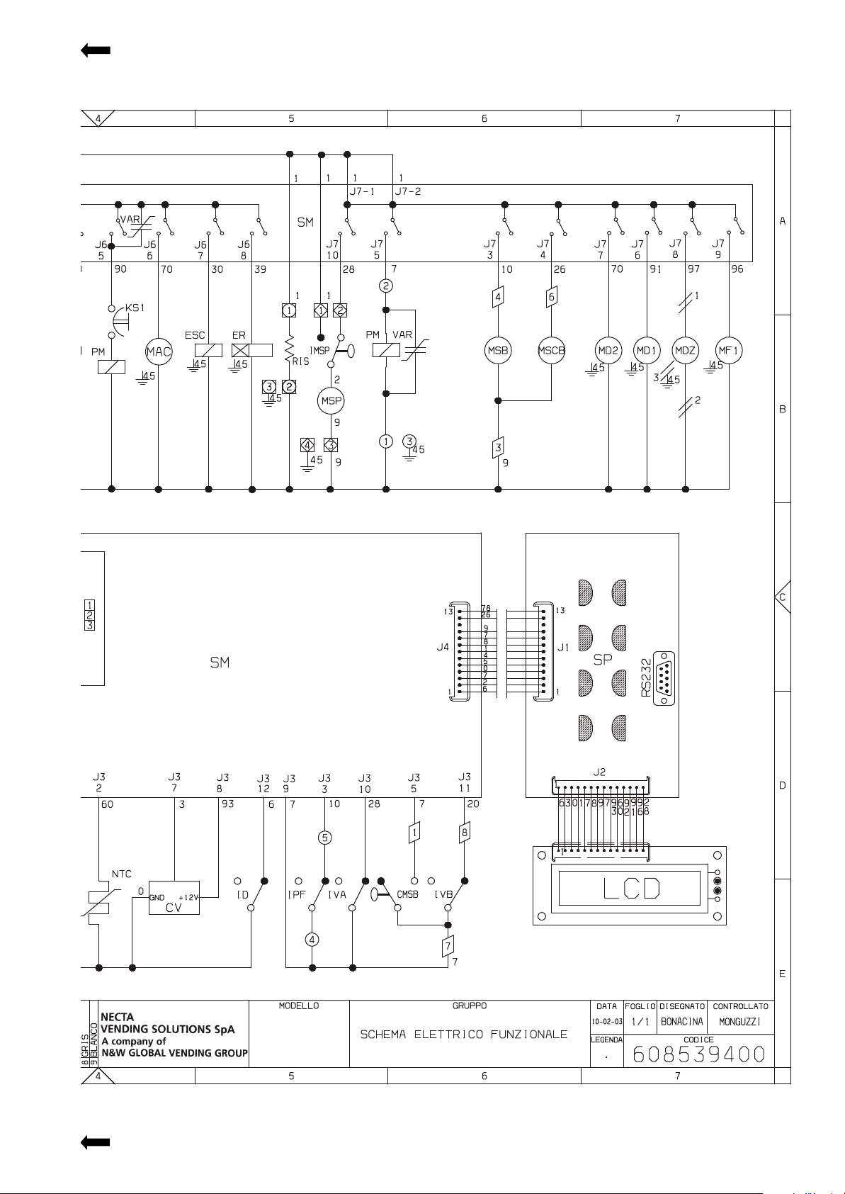
Colibrì
220 V - 60 Hz
Page 46

© by NECTA VENDING SOLUTIONS SpA NOTE
Page 47

The Manufacturer reserves the right to modify, without prior notice, the characteristics of the equipment described in this
publication; and further declines to accept any responsibility for any inaccuracies contained in this publication which can be
ascribed to printing and/or transcription errors.
All instructions, drawings, tables and information contained in this publication are confidential and can neither be reproduced completely or in part, nor be transmitted to third parties without the written permit of the Manufacturer, who has the
sole ownership.
EDITION 1 03-2003 CODE: H 217U 00
Page 48
 Loading...