

TECHNICAL MANUAL “ Brio Easy serving Espresso“
Manual Brio ESE 1 / 17
by
AFTER-SALES SERVICE Hot & Cold
Brio “Easy Serving
Espresso”
BASIC TECHNICAL MANUAL
THE CONTENTS OF THIS DOCUMENT ARE INTENDED FOR NECTA’S AFTER SALES PERSONNEL

TECHNICAL MANUAL “ Brio Easy serving Espresso“
Manual Brio ESE 2 / 17
NOTE
The above units are specific to this machine.
All functional units not mentioned are used also in other machines and are described as such in a separate
manual specific to the relevant range of machines.
View of Brio “ESE” with door open
Table of Contents
1
2
3
4
5
6
7
8
9
Layout
Electrical systems and board connections
Air-break / Boilers
Pumps and by-pass
Coffee brewer unit
Mixer Unit
Powder and water dose tables
Trouble-shooting
Wiring diagrams
Page
Pages
Page
Page
Pages
Page
Page
Pages
Page
3
4/5/6/7
8
9
10/11/12/13
14
14
15/16
17
Cup Dispenser
Sugar and stirrer
release devices
Brewing unit
Powder
containers for
instant drinks
Container for
used co ffee
pods
Sugar container
Safety switch
Cup release and
rotati on unit

TECHNICAL MANUAL “ Brio Easy serving Espresso“
Manual Brio ESE 3 / 17
1 – HYDRAULIC LAYOUT
1 Water inlet solenoid valve 8 “Flow-through” Espresso boiler
2 Mechanical filter for impurities 9 “Flow-through” coil
3 Air-break 10 Three-way solenoid valve 1
4 Volumetric counter 11 Three-way solenoid valve 2
5 Vibration pump 12 ESE coffee pods
6 Pressure boiler for instant drinks 13 Liquid waste float
7 Brewer unit for coffee pods

TECHNICAL MANUAL “ Brio Easy serving Espresso“
Manual Brio ESE 4 / 17
2 - ELECTRICAL WIRING AND BOARD CONNECTIONS
View rear side without casing
The Brio ESE vending machine is fitted with the same actuation
board used on the base model (with a specific Eprom); this board
processes the information from the push-button board, the
payment systems and from the sensors installed throughout the
machine; it also controls the actuations and the display board
It is built on SMT technology.
An additional board was also add ed for the specific “ESE” version,
located in the same compartment and controlling the “flowthrough” espresso boiler
(see
photo).
Two other boards are installed :
1) The display board, which processes the information from the
CPU board and converts it into readable signals, and the pushbutton board.
2) The push-button board that controls the display, the pushbutton actuations; it supports the connectors for the payment
systems.
The CPU/actuation board is set by default to achieve a
temperature of 78-82° C in the Instant boiler.
The espresso boiler cont rol board is set to achiev e a dispensing
temperature of 78-85° C.
See brewer unit paragraph for any corrections.
Machine board
Eprom
Tem perature
control trimmer
Flowthrough
boiler board
Flow-through boiler
temperature contr ol
trimmer
Espresso boiler control
board

TECHNICAL MANUAL “ Brio Easy serving Espresso“
Manual Brio ESE 5 / 17
Push-button board compone nts legend
Ref. N° Description
1 LCD brightness adjustment trimmer
2 Printer connector
3 Prog ramm er device connecto r
4 Machine board connector
5 Payment system configuration minidip
6 Jp2
7 Control board connector 2
8 Executive serial interface
9 Front validator connector
10 Jp1
11 Coin return lamp
12 NOT USED
13 MDB board power supply
14 MDB coin mechanism connector
15 Programming mode button
CPU board component legend
Ref. N. Description
1 Pressure boiler heating elem ent T RIA C
2 Pressure boiler temperature control trimmer
3 Machine configuration minidips
4 EPROM
5 Jumper
1-2 Instant versions
2-3 Espresso versions
6 JS3 - JS4 EPROM version configuration jumpers
Machine board component layout Push-button board component
layout
JS3
JS4

TECHNICAL MANUAL “ Brio Easy serving Espresso“
Manual Brio ESE 6 / 17
RELAY CODE TABLE AND ACTUATIONS
RELAY
CODE
ACTUATION DESCRIPTION
K1
Three-way relief solenoid valve
K2
Three-way relief solenoid valve 2
K3
Instant drink solenoid valve 2
K4
Pump
K5
Coffee brewer motor
K6
Instant drink solenoid valve 2
K7
Pod strip (Serving) drive motor
K8
Mixer motor 1
K9
Doser device 3
K10
Doser device 2
K11
Doser device 1
K12
Sugar doser device
K13
Cup release motor
K14
Stirrer release motor
K15
Cup stacker shift motor
K16
Water inlet solenoid valve
K17
Mixer motor 2

TECHNICAL MANUAL “ Brio Easy serving Espresso“
Manual Brio ESE 7 / 17
MACHINE CONTROL BOARD CONFIGURATION
The machine board is designed with integrated the control system (CPU) and the actuations.
It was also conceived to be used in different machine models.
In the event of replacement it will be necessary to check that the new board configuration is suitable for the
required use.
Proceed as follows:
A series of 8 minidips (3) is located at the centre of the board permitting its configuration for use in the
different versions and countries. A jumper (5) is used to configure the board for Instant or Espresso
versions. The board has also provisions for supporting 512 Kb and 1 Mb EPROMs by setting Jumpers JS3
and JS4.
For the different configurations see the following tables:
LANGUAGE CONFIGURATION
LANGUAGE
Minidip Italian French Spanish
6 OFF ON OFF
7 OFF OFF ON
MODEL CONFIGURATION
Model Espresso
MINIDIP 5 OFF
Jumper 2 - 3
STIRRER CONFIGURATION
STIRRER
Dispensed also with
unsweetened
selection s
Not dispensed
with unsweetened
selection s
MINIDIP 2 ON OFF
PAYMENT SYSTEM CONFIGURATION (FRONT COIN MECHANISM)
MINIDIP
ON OFF
1 - Fixed to OFF
3
(validator only)
Credit control No credit control
4 - Validator
8 - Fixed to OFF
PAYMENT SYSTEM CONFIGURATION (SERIAL COIN MECHANISM)
SERIAL SYSTEM
DIP 3
DIP 4
DIP 5
Executive s td.
U-Key URW 2
OFF OFF OFF
Executive Price
Holding
Parameter 36 = 2 )
OFF O N OFF
System ECS
ON OFF OFF
U-Key URW 3
OFF OFF ON
IMPORTANT NOTICE
Minidips that are not mentioned must be set to OFF.
TECHNICAL MANUAL “ Brio Easy serving Espresso“
Manual Brio ESE 8 / 17
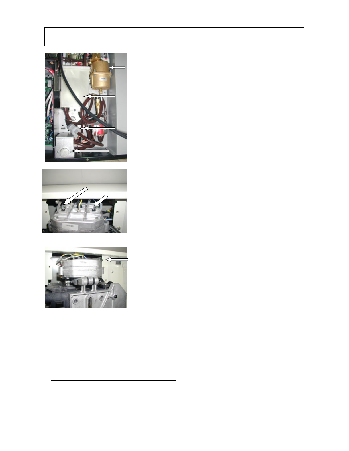
3 - AIR BREAK / BOILERS
The Brio ESE vending machine is fitted with
two boilers, each for a specific function.
A classic pressure boiler is used for Instant
selections, normally fitted on the Base Brio as
an all-purpose boiler, but it is kept at an internal
pressure of 10 bar by means of specific setting
of the by-pass valve.
A “flow-through” boiler is used for Espresso
selections; this boiler receives water from the
base pressure boiler preheated at a temperature
of approximately 80° C and then heats it up to
95-100° C.
This solution ensures a long operating life
without premature scaling problems.
It is well known that in flow-through boilers,
where water is heated from ambient
temperature to brewing temperature in a very
short time, very shortly there are problems with
excessive scaling.
The hydraulic circuit is conceived as follows:
When the water in the air-break falls below the
minimum level, a float triggers a microswitch
that sends a signal to the board, which activates
the water inlet solenoid valve “A”, then the
water flows through the filter “B” and reaches
the air-break “C” until it is full to the max level,
controlled by the float and microswitch.
When a coffee selection is made, after
positioning the pod in the brewing chamber, the
pressure boiler two-way solenoid valves is
opened and the vibration pump is started for a
length of time determined by the volumetric
counter, that by computing the number of
rotations of an impeller wheel sets the exact
amount of water necessary for the selection.
The necessary amount of water is drawn from
the air-break and sent to the pressure boiler,
thus pushing out the same amount of hot water
(85° C) which is then delivered to the glowthrough boiler, and heated up to 95° C by
means of forced flow through a coil heated by
the Espresso boiler heating element. This water
is controlled by a pair of three-way solenoid
valves, allowing the flow of water for brewing
and for relieving the excess water in the pod,
thus leaving a perfectly dry pod
Pressure boiler
for instant
drinks
Air –break “C”
filter for
impurities “ B
”
Elettrovalvola ingresso
acqua "A ”
“
Flow-through”
Espresso boiler
Overheating protection
thermo-fuses
NOTE: The pressure boiler is fitted with manual reset
overheating protection.
The flow-through Espresso boiler is fitted with
overheating protection provided by two accurate
thermo-fuses calibrated at 120° C; these fuses must
be repl aced after they are trigg ered.
Before resetting or replacing the above protections,
the problem that caused the trigger must be identified
and corrected.

TECHNICAL MANUAL “ Brio Easy serving Espresso“
Manual Brio ESE 9 / 17
4 – PUMPS AND BY – PASS
A standard vibration pump is used, also adopted on the
base Brio, and fitted with overheating protection;
however a by-pass pre-set at 10 bar is installed, to
avoid un uneven use of the coffee pod and thus
ensuring better dispensed product quality.
To ensure greater pump reliability and better tightness
against the pressure, a check valve was added at the
boiler inlet, this way no anomalous leads are exerted on
the pump when idle.
Also the pump is fitted with a check valve, thus ensuring
optimum tightness against the boiler internal pressure.
By-pass
Vibration
pump
Check valve
Water delivery to
boiler
Connection to the
water mains
Air-break

TECHNICAL MANUAL “ Brio Easy serving Espresso“
Manual Brio ESE 10 / 17
5 - BREWER UNIT FOR COFFEE PODS
The adopted brewer unit is used to brew coffee exclusively by means of
continuous strip “ESE” pods (servings) with 100/200 doses. The pods
are made up with an optimum coffee dose.
The unit works as follows:
When a selection is made the serving drive motor positions the pod in
the brewing zone under the flow-through boiler. The unit motor lifts the
piston until hermetically closing the brewing chamber.
The three-way solenoid valve is opened so that the pressure boiler is
connected to the flow-through boiler located above the brewer unit.
The pressure boiler maintains the water at a temperature of
approximately 80° C (ideal for instant products) and the flow-through
boiler heats it up to 95-100° C (ideal for espresso coffee).
The brewing chamber is kept hot at
the same temperature of the flowthrough boiler.
The pump delivers the programmed amount of water that is accurately
computed by the volumetric counter. At the end the three-way solenoid
valves are closed and the water still in the flow-though boiler is expelled
through the third way of the valve. Then the unit motor is activated,
lowering the piston until opening the brewing chamber.
The “serving” drive motor is started, dragging the serving out of the
brewing chamber.
At this point the unit is ready for a new selection.
In order to maintain the correct temperature up to the dispensing point, a
special tube heated by a special permanent low-consumption heating
element is used.
Pod strip drive motor
Unit drive motor
Inner piston
Three-way solenoid valve
Pod strip (Serving) drive roller
Microswitches
Rear view of brewer unit
“
Flow- through”
Boiler
Brewing
unit
Heated tube
Heated tube power
supply cable

TECHNICAL MANUAL “ Brio Easy serving Espresso“
Manual Brio ESE 11 / 17
BREWER UNIT MAINTENANCE
Before any maintenance operations and adjustments it is necessary to wait for the unit to cool down
completely.
Cleaning / replacing the coffee filters
The coffee filters must be cleaned and descaled at least every 2500 selections. To remove the lower filter,
the flow-through boiler must be lifted (hinged to the brewer) after removing the keys 1 (front and if
necessary back), this way access is gained to the lower filter; using a screwdriver lift the edge until removed
completely. Clean and descale using suitable products. To replace the filter, press on the edges until
reinserted completely.
Upper filter
To remove the upper filter 2, undo the stainless steel screw
1.
This operation is possible after removing the upper boiler (see
above).
Filters and gaskets must be replaced not later than 25000
selections.
Upper boiler
opening keys
Lower piston
Lower filter
1
2
Boiler and brewing chamber section
1
TECHNICAL MANUAL “ Brio Easy serving Espresso“
Manual Brio ESE 12 / 17
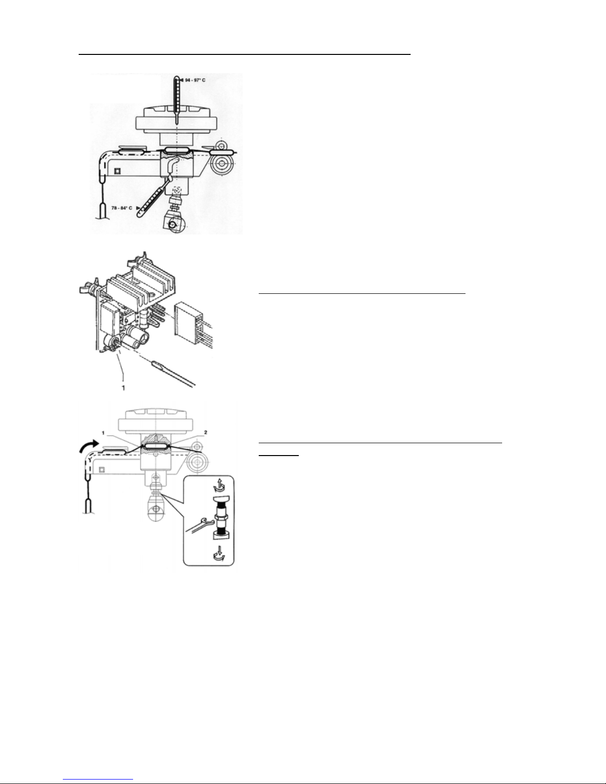
Setting the coffee water temperature (flow-through boiler)
The optimum temperature is set at the factory; should any
adjustments and small changes be necessary, proceed as
follows: Check the upper flow-through boiler temperature, which
must be between 94° and 97° C. This way the dispensing
temperature will be 78° to 84° C.
Such temperature must be considered as optimum.
If that is not the case, adjust the temperature using the trimmer
1 on the electronic board located at the back of the cabinet next
to the machine board.
It must be taken into account that:
Tightening will decrease the temperature
Loosening will increase the temperature
Make very small adjustments and check the dispensing
temperature. The instant boiler inlet water temperature is
determined by the instant boiler temperature, as pre-heated
water is sent to the flow-through boiler to reduce to a minimum
the scaling problem typical of such boilers. For adjustments to
the instant boiler see paragraph Boilers.
ADJUSTING THE POD HOLDER CLOSURE
In order to dispense a perfect coffee with the pod brewer it is
very important to have a perfect setting on the closing position.
The system is adjusted to the optimum setting at the factory,
however in the event of disassembly for cleaning and/or
replacing filters and gaskets it may be necessary to readjust the
settings; in this case proceed as follows:
To increase tightness between gasket 1 and filter 2 rotate the
pin clockwise using an 11 mm spanner.
To decrease tightness in the case of excessive interference the
pin must be rotated anticlockwise.
After the adjustment, the system is self-locking.
PERIODIC CLEANING OF THE FLOW-THROUGH
BOILER
At least once a year, or not later than 10000 selections, the
flow-through boiler must be cleaned and if necessary descaled;
at the same time the sealing gasket must be replaced.
In order to remove the boiler it is advisable to extract the brewer
unit from the machine.
Before any operations the vending machine must be
disconnected from the power supply, and the unit must cool
down completely. Disconnect the hydraulic circuits, disconnect
the electrical connectors, completely undo the fastening screws
and remove the unit from the machine. Remove the two
securing keys from the upper boiler.
Proceed to cleaning, descaling and any replacement of worn components; thoroughly rinse and reassemble in the
reverse ord er of disassembly .
Checking
dispensing
temperature
Flow-through boiler temperature
Measuring upper boiler
temperature
Adjustment pin for the
brewing chamber
closure

TECHNICAL MANUAL “ Brio Easy serving Espresso“
Manual Brio ESE 13 / 17
BREWER UNIT CLEANING CYCLE
As well as manual cleaning through setting in the “Maintenance” menu, anyway performed without
“Serving”, an automatic cleaning cycle can be set.
After a selection, if a new “Serving” is not detected within 20 seconds, a cleaning cycle is carried out and the
vending machine will be out of service for approximately 60 seconds.
Manual cleaning must be carried out every time new “Servings” are loaded; it is however advisable to leave
the automatic cycle control set at all times.
CHECKING AND ADJUSTING THE COFFEE DISPENSING PARAMETER SETTINGS
In order to get the best possible quality for the dispensed products, the vending machine was adjusted to
the optimum setting at the factory; however in relation to the products used it is advisable to check the
following points:
The water dose, which must be between 35 and 40 cc.
The coffee dispensing tempe ratu re, which must be between 78° e 85° C.
The pump by-pass valve setting, adjusted to 10 bar by default.
The dispensing time, which must be between 18 and 20 seconds, considering that a longer time (with the same water
dose) could to clog filters, and a shorter time could alter the by-pass setting towards a higher pressure, and lead to
poorer dispensing quality.
STANDARD SETTINGS
By default the vending machine is adjusted at the factory as follows:
Coffee temperature at the spout, 78-85° C
Instant boiler temperature, 78-82° C
Dispensing time, 18 to 20 seconds
Coffee water dose, 35 to 40 cc
ADJUSTING THE INSTANT BOILER WATER TEMPERATURE
The instant boiler has a dual function: it provides hot water for all instant products by means of its two-way
solenoid valve.
It pre-heats water for the flow-through boiler to avoid the scaling problem typical of such type of boiler.
It is therefore important to have an optimum setting, as a temperature change affects also the final
temperature of the coffee.
To change such temperature the special trimmer on the machine board must be used.
Considering that:
Tightening (clockwise) will increase the temperature
Loosening (anticlockwise) will decrease the temperature
Each complete turn correspond to +/- 0.5° C change
BOILER OVERHEATING PROTECTIONS
The boilers are fitted with safety overheating protections.
The espresso boiler is fitted with two thermo-fuses located above it and sheathed in a special silicone tube.
In the event of failure that could cause boiler overheating, the two thermo-fuses melt, thus disconnecting
the power from the heating element.
After the occurrence of such melting, the problem that caused the malfunction must be identified, corrected
and BOTH THERMO-FUSES MUST BE REPLACED with identical ones or having the same characteristics.
Fuses must never be replaced with others that are not approved by the manufacturer, otherwise hazard
conditions could be created and the manufacturer declines all responsibility.
The instant boiler is fitted with manual reset overheating protection; therefore after having identified and
corrected the cause it is sufficient to press the upper red button to restore the initial conditions.

TECHNICAL MANUAL “ Brio Easy serving Espresso“
Manual Brio ESE 14 / 17
6 – MIXER UNIT
The mixer units are the same used on the Base Brio vending machine.
Motors powered with 230 V AC 50 HZ
Loadless velocity 20000 RPM
Removable powder exhaust drawer and conveyors.
Conforming with HACCP directive.
Bush seal made of self-positioning material, ensuring excellent and long
lasting seal in all conditions.
7 - POWDER AND LIQUID DOSE TABLES
Selection Notes coffee Coffee
Instant
Water
cc
Powder
gr.
Sugar
gr.
Notes
Short coffee
Time
Quantity
Pre-set
dose in a
pod
-
35”
60 cdv
40 c.c.
7,5 gr
CDV =
Wheel
counts
Long coffee
Time
Quantity
Pre-set
dose in a
pod
-
38”
95 cdv
60 c.c.
7,5 gr
Coffee with
milk
Time
Quantity
Pre-set
dose in a
pod
-
38”
60+35 cdv
42+25 cc
2,0 gr latte
7,5 gr
Cappuccino
Time
Quantity
Pre-set
dose in a
pod
-
45”
60+72 cdv
40+55 cc
6,0 gr latte
7,5 gr
Instant Coffee
(Optional)
Time
Quantity
1,3 gr.
22”
55 cdv
40c.c.
-
7,5 gr
Chocolate
Time
Quantity
32”
116 cdv
90 c.c.
23-28 gr.
-
Instant tea
Time
Quantity
32”
116 cdv
90 c.c.
12-14 gr.
-
Milk
Time
Quantity
32”
116 cdv
90 c.c.
8 gr.
7,5 gr
Note 1
The water fl ow in the mi xers is appro ximately 10 cc per second and it i s gi ven as an indicati on, as ther e are many var iables that can
affect the accur acy.
The dose of liquids is determined by pulse setting of the volumetric counter (cdv).
For both selections (coffee and instant) a vibration pump is used.
The number of pulses does not vary in a linear manner, i.e. double the amount of water does not correspond to double the number of
pulses.
For espresso coffee the volum etri c counter is reduced b ecause o f the coffee co mpress reaction that slows down the water flow, while it
is accelerated in the instant drinks selections, since ther e are no o bstr uctions to the w ater flow. T herefor e, in the event of changing the
defaul t dose setting, some measurements must be made to ch eck the accur acy of the doses.

TECHNICAL MANUAL “ Brio Easy serving Espresso“
Manual Brio ESE 15 / 17
8 – TROUBLE-SHOOTING
Problem
(and/or indication on the
display)
Possible cause Solution
The machine does not go into
the heating phase, remaining
in the installation phase
No water flow from the mains or insufficient
pressure (it must be 5-85 N/cm2)
The air-break mi croswitch is faul ty
Water inlet solenoid valve blocked by the overflow
drain of the air-break.
Water inlet solenoid valve not activated because of
faulty RELAY K16
Check the presence of one or more of
situations indicated and o nce identified the
cause do as follows:
Short-ci rcuit the air-break m icroswitch to
check its functioning
In the event of failure, r eplace with a new
that MUST HAVE the same characteristi cs
Unlock the water inlet valve, undoing the
threaded ri ng and emptyi ng the overflow
tube
Check for 230 V AC voltage at the power
supply terminals
Check the activa tion of relay K16
The display indicates the
message“No coffee”
Coffee pod spent or faulty pod detection
microswitch
Faulty “SERV ING” drive motor
Pod drive locked
Faulty RELA Y K7
When a coffee selection is made, the
“SERVING” drive ratiomotor is activated, and
the mo vement activates a microswitch. If
such m icroswitch i s not activated within 5
seconds, the SW disables all coffee based
functions.
Check for one or more of the situations
indicated
The display indicates the
message“Boiler failure”
The boi ler does not reach the operating
temperature
Faulty temperature probe
Overheating protection triggered
For the espresso boiler, melted thermo-fuse
The vending machine is locked if the set
temperature is not reached within 10
minutes.
Check the correc t operation of the heating
element, the probe and of the ac tuation triac.
NOTE:
1) at 25° C the probe must have a resistance
of 12 k ohm
2) at 100°C C the probe must have a
resistance of 963 ohm
(± 4 ohm tolerance)
3) In the even t of faulty flow-through boiler,
the problem is not signaled by the SW,
therefo re it must be ch ecked wh ether the
thermo-fuse was triggered or the failure is in
the power supply board (specific)
The display indicates the
message “No cups”
No cups in the dispenser
Faulty cup detection microswitch
Faulty RELAYS K13-15
If no cups were present when starting the
machi ne, the column rotation rati omotor is
activa ted to search for a full column and i f no
cups are found within a 60 sec (i ndicated by
the speci fic cup detection microswitch) the
machine is locked.
Excluding the fact of a r eal lack of cups, the
correct microswitch functioning must be
checked and in the event of fail ure it MUST
BE replaced with an identi cal one.
In the event of locked release motor o r
column motor, check for the correct a ctua tion
of relays K13-15.
The display indicates the
message
“Brewer unit”
The unit failed to reposition.
Faulty unit positioning microswitch (upper dead
centre)
Faulty unit positio ning microswitch (lower dead
centre)
Faulty RELA Y K5
Check the correct functioning of the upper
and lower position microswitch using a
multimeter
In the event of correct fun ctio ning, check the
correct setting.
In the end, check the correct setting of the
adjustable rod that closes the b rewing
chamber.

TECHNICAL MANUAL “ Brio Easy serving Espresso“
Manual Brio ESE 16 / 17
The display indicates the
message
“Volumetric counter”
(Wheel)
The expected liquid dose is not reached (computed)
within 60 seconds from starting the selection.
The water am ount for bo th espresso coffee
and instant drink selections is ensured by a
volumetric co unter; with the water flow
(drawn by the pump) a wheel ro tates and
through an electronic sensor sends a number
of pulses, and when the number of pulses
corresponding to the water dose set during
programming is reached, the pump is
stopped.
If such value is not reached within 60 sec it
means that there is a probl em:
Then, check for the correc t functioning of the
volumetric counter; there must be 5 V AC on
the term inals duri ng the counter operati on.
Check that the filters are not cl ogged.
Check that the by-pass is no t locked o pen.
The display indicates the
message “Air-break failure”
No water from the mains.
Faulty air- break mi croswitch
Failure to the level detection system (float)
If in the period taken to make any 6
selection the microswitch controlled
by the float is not triggered, the
vending machine is locked for airbreak failure.
The malfuncti on could occur for lack o f water
from the mains, or because of a failure to the
float/microswitch system.
Replace the microswitch with one that MUST
HAVE the same characteristics.
Otherwise various malfunctions could occur.
The display indicates the
message “RAM data”
System lock
Wrong RAM data, which must be retrieved by
initialising the EPROM.
Access the installation procedure and initialise
the Software.
If the problem persists, replace the entire
CPU board.
The display indicates the
message“Coin mech failure”
If the ere is no communi cation between coin
mechanism and CPU board for 30 seco nds (for
serial coin mechanisms only)
Check for correct connection and
configuration of the minidips, if all correct
replace the coin mechanism.
The display indicates the
message“Water failure”
Models with water supply from the m ains:
If the air-break microswitch is activated for more
than a minute
Models with water supply from an i nternal tank:
If the water level is less than 300 cc
Check the water inlet solenoid valve.
Check the correct actuation of relay
K 16
Check the air-break microswitch functioning.
Check the float/microswitch system
functioning.
Coffee is dispensed too
slowly and it tastes burnt
Faulty pump by-pass (open)
Clogged coffee filters.
Excessive t emperature in the flo w-through boil er
Flow-through coffee boiler clogged
Replace the by-pass valve with o ne s et at 10
bars. Consider that coffee must be dispensed
in a maximum time of 15 to 20 seconds;
longer times can clog the filters.
The coffee is dispensed too
quickly and lacks body and
cream
Faulty pump by-pass (closed)
Insufficient tem perature in the flow-through bo iler
Faulty heating element in the he ating pipe
Replace the by-pass with one set at 10 bars.
Check for the cor rect temp erature, which
must be between 95° and 97° C.
Check that there is flow i n the dispensing
tube and that the temperatur e i s at least 60°
C.
Check the functi oning of the specific power
supply board.
Check that the thermo-fuse was not
triggered; if triggered replace with one
having the same ch aracteristics.
The mixers clog up
The whipper failed to rotate
Powder removal drawer full
Insuffici ent water to powder ratio.
Check for the mixer motor overheat
protection trigger, if that is the case check
the cause of such trigger. Empty the powder
collection drawers and check the functioning
of steam suction fan.
Check the powder/li quid setting
TECHNICAL MANUAL “ Brio Easy serving Espresso“
Manual Brio ESE 17 / 17
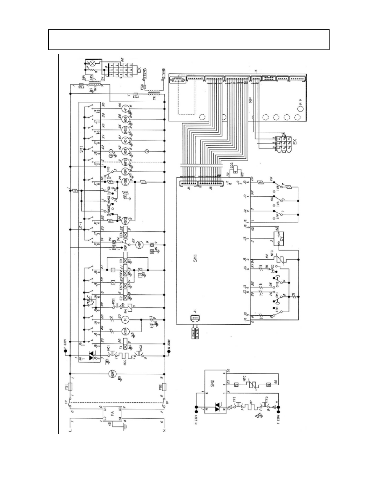
9 - WIRING DIAGRAMS
 Loading...