

Page 1

PROPRIETARY NOTICE AND LIABILITY DISCLAIMER
The informa tion disc losed in this docu ment, inc luding a ll des igns a nd r ela t ed mat eri a ls, is t he
valua ble pr oper ty of NEC Compu ter S yst ems Division, P acka r d Bell NE C, Inc. ( NEC CS D,
PBNE C) and/ or it s licensors . NEC CS D and/or its lic ensors, as a ppr opr iate, reserve a ll pa tent, copyright and other proprieta ry rights to this document, including a ll design, manu f acturing, r epr oduct ion, u se, a nd sa les r ight s ther eto, except to t he ext ent s aid r ights a re ex pr essly
granted to others.
The NEC CSD produ ct(s) disc ussed in this document a re warr anted in acc ordance with t he
terms of the Wa r ra nt y St at ement acc ompanying ea ch p rodu ct. However , a ct ua l p erfor manc e
of each s uc h product is dependent u pon f a ct or s su ch a s s yst em configu r a t ion, c us t omer da t a ,
and operator control. Since implementation by customers of each product may vary, the
suitability of specific product configurations and applications must be determined by the
customer and is not warranted by NECCSD.
To allow for design and specification improvements, the information in this document is
subject to change at any time, without notice. Reproduction of this document or portions
thereof without prior written approval of NECCSD is prohibited.
NEC is a registered trademark, Versa is a U.S. registered trademark, VersaGlide, and PortBar are trademarks, and UltraCare is a
U.S. registered service mark of NEC Corporation, used under license.
FaxFlash is a service mark of NEC Computer Systems Division (NECCSD), Packard Bell NEC, Inc.
All other product, brand, or trade names used in this publication are the property of their respective owners.
Second Printing — November 1997
Copyright 1997
NEC Computer Systems Division, Packard Bell NEC, Inc.
1414 Massachusetts Avenue
Boxborough, MA 01719
All Rights Reserved
Page 2

Preface
This service and reference manual contains the technical information necessary to set up and
maintain the NEC Versa® 2700 Series notebook computer. It also provides hardware and
interface information for users who need an overview of the system’s design. The manual is
written for NEC-trained customer engineers, system analysts, service center personnel, and
dealers.
The manual is organized as follows:
Section 1 Technical Information, provides an overview of the hardware and interface
components.
Section 2 General Specifications, lists system specifications including dimensions,
weight, environment, safety compliance, and power consumption.
Section 3 Hardware Functional Overview, defines major system functions and subsys-
tems.
ix
Section 4 Troubleshooting and Repair, lists technical support phone numbers, error
messages and their meanings, and ways to troubleshoot problems users encounter with the
notebook.
Section 5 Field Service Guidelines, provides system disassembly procedures, and an
exploded-view diagram with corresponding part numbers.
Appendix A Video Modes, provides a list of video modes available for use with the
notebook.
An Index is included for convenience.
Page 3
(For United States Use Only)
FEDERAL COMMUNICATIONS COMMISSION
RADIO FREQUENCY INTERFERENCE STATEMENT
!
Changes or modifications to this unit not expressly approved by the party responsible for
compliance could void the user’s authority to operate the equipment.
NOTE
with the lim its for a Class B digit al device, pursuant to Part 15 of the FCC Rules. These lim its
are designed to provide reasonable protection against harmful interference in a residential
installat ion. This equipm ent generates, uses and can radiate radio fr equency energy and, if not
installed and used in accordance with the instructi ons, may cause harm ful interference to radi o
communications.
However, there is no guarantee that interference will not occur in a particular installation. If this
equip men t does cause h ar m ful in terferen ce to ra di o or tel evisi on r ecept i on, wh ich can be det er mi n ed by
tur ning th e equipmen t off and on, the user i s encoura ged to try to corr ect the i nterfer ence by one or
more of the following measures.
This is a Class B Digital Device. This equipment has been tested and found to comply
WARNING
Reorient or relocate the receiving antenna.
Increase the separation between the equipment and receiver.
Connect the equipment to an outlet on a circuit different from the one to which the receiver is
connected.
To meet FCC standards, shielded cables and power cords are required to connect this device to a
personal computer or other Class B certified device.
Canadian Department of Communications Compliance Statement
This equipment does not exceed the Class B limits for radio noise emissions from digital apparatus set out in the Radio interference
Regulations of the Canadian Department of Communications.
Avis de conformité aux normes du ministère des Communications du Canada
Cet appareil respecte les limites de bruits radioélectriques applicables aux appareils numériques de Classe B prescrites dans le Règlement sur
le brouillage radioélectrique édicté par le ministère des Communications du Canada.
European Community Directive Conformance Statement
This product is in conformity with the protection requirements of EC Council Directive 89/336/EEC on the approximation of laws of the
Member States relating to electro-magnetic compatibility. This product satisfied the Class B limits of EN 55022.
NEC Computer Systems Division, Packard Bell NEC, Inc.
1414 Massachusetts Avenue
Boxborough, Massachusetts 01719
1-800-632-4525
Page 4

Contents
Preface......................................................................................................................... ix
Abbreviations............................................................................................................... xi
Section 1 Technical Information
Feature Highlights........................................................................................................1-3
System Configuration...................................................................................................1-5
Quick Tour of the Notebook........................................................................................1-6
Main Components.................................................................................................1-6
Color LCD Display Panel...............................................................................1-6
Power Button/LCD Cover Switch..................................................................1-7
Status Panel and Power Indicator...................................................................1-7
Keyboard.......................................................................................................1-8
VersaGlide.....................................................................................................1-10
iii
Under the Palm Rest in Front of the Notebook......................................................1-10
Hard Disk Drive.............................................................................................1-10
Memory Module Compartment ......................................................................1-11
Right Side of the Notebook...................................................................................1-11
Non-Removable Floppy Disk Drive................................................................1-11
Battery Compartment.....................................................................................1-11
DC-IN Connector Jack...................................................................................1-12
Left Side of the Notebook.....................................................................................1-13
PC Card Slot Compartment............................................................................1-13
The USB Connector.......................................................................................1-14
The FIR Window...........................................................................................1-14
The Audio Jacks and Thumbwheel Volume Control .......................................1-14
The Fax/Modem.............................................................................................1-15
Rear of the Notebook............................................................................................1-15
External Keyboard and PS/2 Mouse Port .......................................................1-15
VGA Port......................................................................................................1-16
Printer Port....................................................................................................1-17
Serial Port (COM1)........................................................................................1-17
System BIOS Setup Program.......................................................................................1-18
The Boot Setup Menu..................................................................................................1-19
System Upgrades.........................................................................................................1-28
Page 5

iv Contents
Section 2 General Specifications
System Board Specifications........................................................................................2-5
DC Converter Board Specifications..............................................................................2-7
LED Indicator Board Specifications.............................................................................2-9
I/O Board Specifications..............................................................................................2-9
LCD Inverter Board Specifications ..............................................................................2-10
LED Status Indicators..................................................................................................2-11
Diskette Drive Specifications .......................................................................................2-11
HDD Unit Specifications..............................................................................................2-12
CD-ROM Specifications ..............................................................................................2-12
NIMH Battery Pack Specifications...............................................................................2-12
DC/DC Converter And Battery Charger Specifications.................................................2-13
Battery Charger Specifications..................................................................................... 2-13
Keyboard Specifications...............................................................................................2-14
AC/DC Adapter Specifications.....................................................................................2-14
LCD/LED Board Specifications...................................................................................2-15
BIOS Specifications.....................................................................................................2-16
Power Management Features (Mode Definition) ..........................................................2-17
Power Management Features (Mode Transition)..........................................................2-19
Hot Key Definition.......................................................................................................2-19
Hot Keys Supported By External Keyboard Definition.................................................2-20
Environmental Specifications .......................................................................................2-20
Power Source Specifications........................................................................................2-20
Vibration Specifications ...............................................................................................2-21
Shock Specifications.................................................................................................... 2-21
Electro-Static Discharge (ESD) Specifications.............................................................2-21
Section 3 Hardware Functional Overview
Functional Block Diagram............................................................................................3-2
System BIOS............................................................................................................... 3-3
System Processor..................................................................................................3-3
System Logic Controller ..............................................................................................3-4
Memory Subsystem......................................................................................................3-6
DRAM Memory....................................................................................................3-6
ROM Memory ......................................................................................................3-6
I/O Subsystem .............................................................................................................3-6
VIDEO Subsystem.......................................................................................................3-9
Page 6

Contents v
External VGA Capability.......................................................................................3-11
Keyboard Subsystem....................................................................................................3-12
PCMCIA Controller And Sockets................................................................................3-12
Hard Disk Subsystem...................................................................................................3-14
Diskette Drive Subsystem ............................................................................................3-14
Pointing Device Subsystem ..........................................................................................3-14
Power Subsystem.........................................................................................................3-14
AC Power Adapter ...............................................................................................3-15
Internal Battery Pack ............................................................................................3-15
Power Board.........................................................................................................3-15
LCD Inverter Board Assembly.............................................................................. 3-15
Section 4 Troubleshooting and Repair
Service Information......................................................................................................4-1
Technical Support........................................................................................................4-1
Product Information.....................................................................................................4-2
Helpful Starters............................................................................................................4-3
Power-On Self Test (POST) ........................................................................................4-4
POST Messages....................................................................................................4-4
Beep Codes...........................................................................................................4-6
Informational Messages.........................................................................................4-8
Run-time Error Messages......................................................................................4-9
Quick Troubleshooting ................................................................................................4-10
Section 5 Field Service Guidelines
Preventive Maintenance ...............................................................................................5-1
Cleaning the Notebook’s Exterior.........................................................................5-1
Cleaning the Notebook’s Interior ..........................................................................5-2
Protecting the Disk Drives ....................................................................................5-2
Handling the Computer Battery Packs...................................................................5-2
Maintaining the LCD Quality ................................................................................ 5-3
Required Tools And Equipment...................................................................................5-3
Parts Removal And Replacement Procedures ...............................................................5-4
Removing/Replacing the Notebook Battery Pack ..................................................5-4
Removing/Replacing the Hard Disk Drive Module ................................................5-4
Removing/Replacing the CMOS Battery ...............................................................5-5
Removing/Replacing the Fax/Modem....................................................................5-5
Page 7

vi Contents
Removing/Replacing the Keyboard and LCD Assembly.........................................5-6
Memory Upgrade Procedure........................................................................................5-6
HDPREPEZ Utility...............................................................................................5-10
Changing Switch Settings Procedure.....................................................................5-11
Sealant Replacement Procedure......................................................................5-13
System BIOS Upgrade Procedure................................................................................5-14
Removing/Replacing the CPU Module..................................................................5-15
Removing/Replacing the NEC VersaGlide Assembly.............................................5-16
Removing/Replacing the LED Board.....................................................................5-16
Removing/Replacing the System Board.................................................................5-17
Illustrated Parts Breakdown.........................................................................................5-18
Packaging and Documentation..............................................................................5-21
Index
List of Figures
1-1 NEC Versa 2700 Series Notebook.................................................................1-3
1-2 System Configuration Diagram.......................................................................1-5
1-3 LCD Panel.....................................................................................................1-6
1-4 System Status LED Panel...............................................................................1-7
1-5 Device Status LED Panel...............................................................................1-7
1-6 Standard Keyboard Layout.............................................................................1-8
1-7 VersaGlide.....................................................................................................1-10
1-8 Memory Module Sockets...............................................................................1-11
1-9 Connecting the AC Adapter to the Notebook.................................................1-12
1-10 Left Side of the Notebook..............................................................................1-13
1-11 Inserting a PC Card........................................................................................1-14
1-12 Rear Side of the Notebook.............................................................................1-15
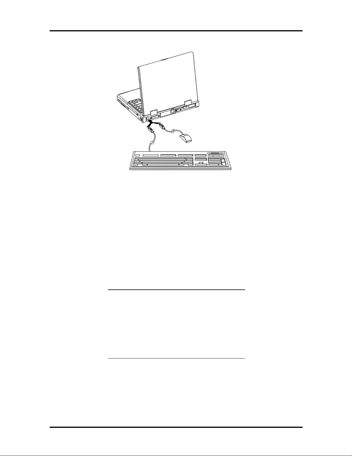
1-13 Connecting an External Keyboard and PS/2 Mouse........................................1-16
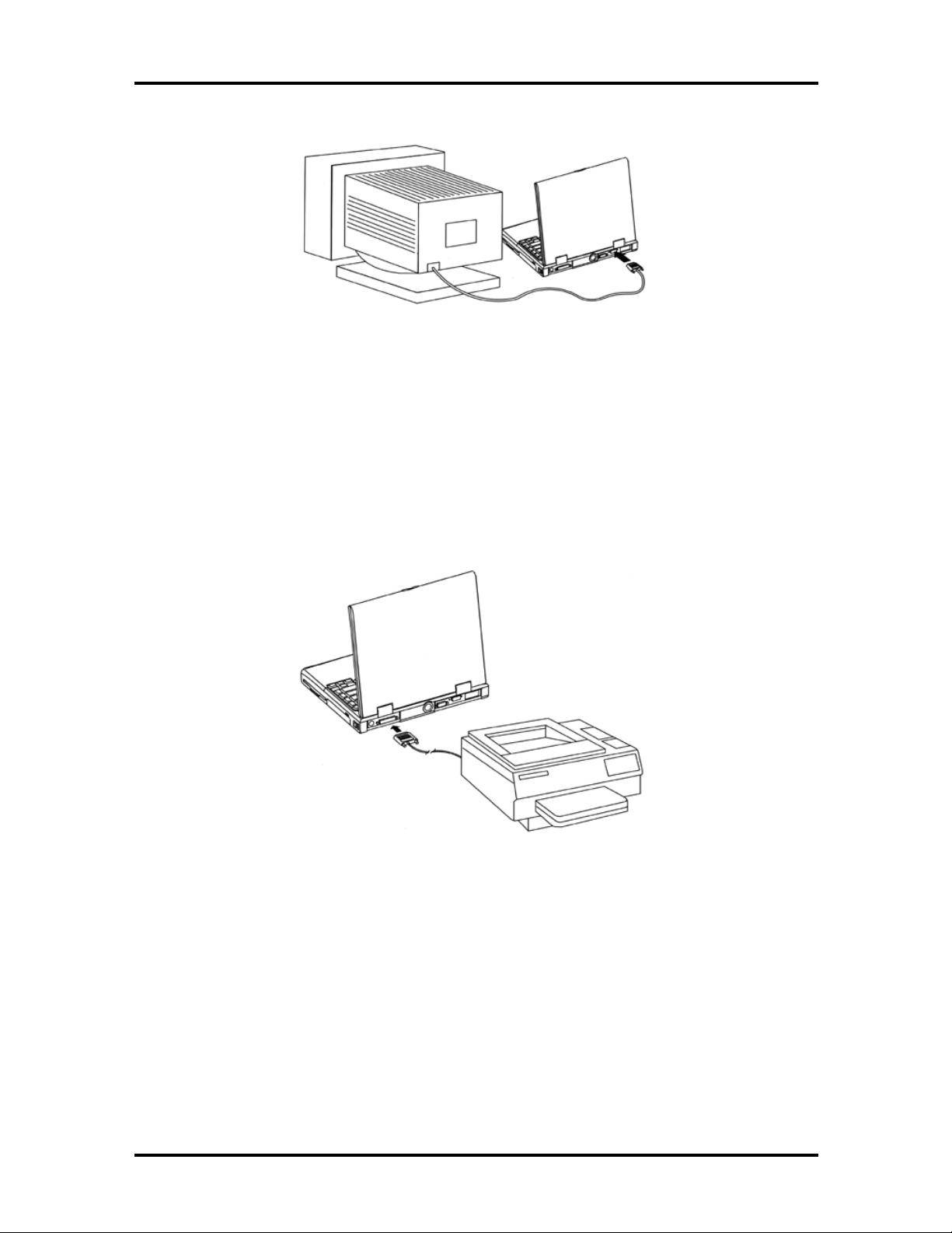
1-14 Connecting an External Monitor.....................................................................1-17
1-15 Connecting to the Printer Port........................................................................1-17
1-16 Connecting to the Serial Port .........................................................................1-18
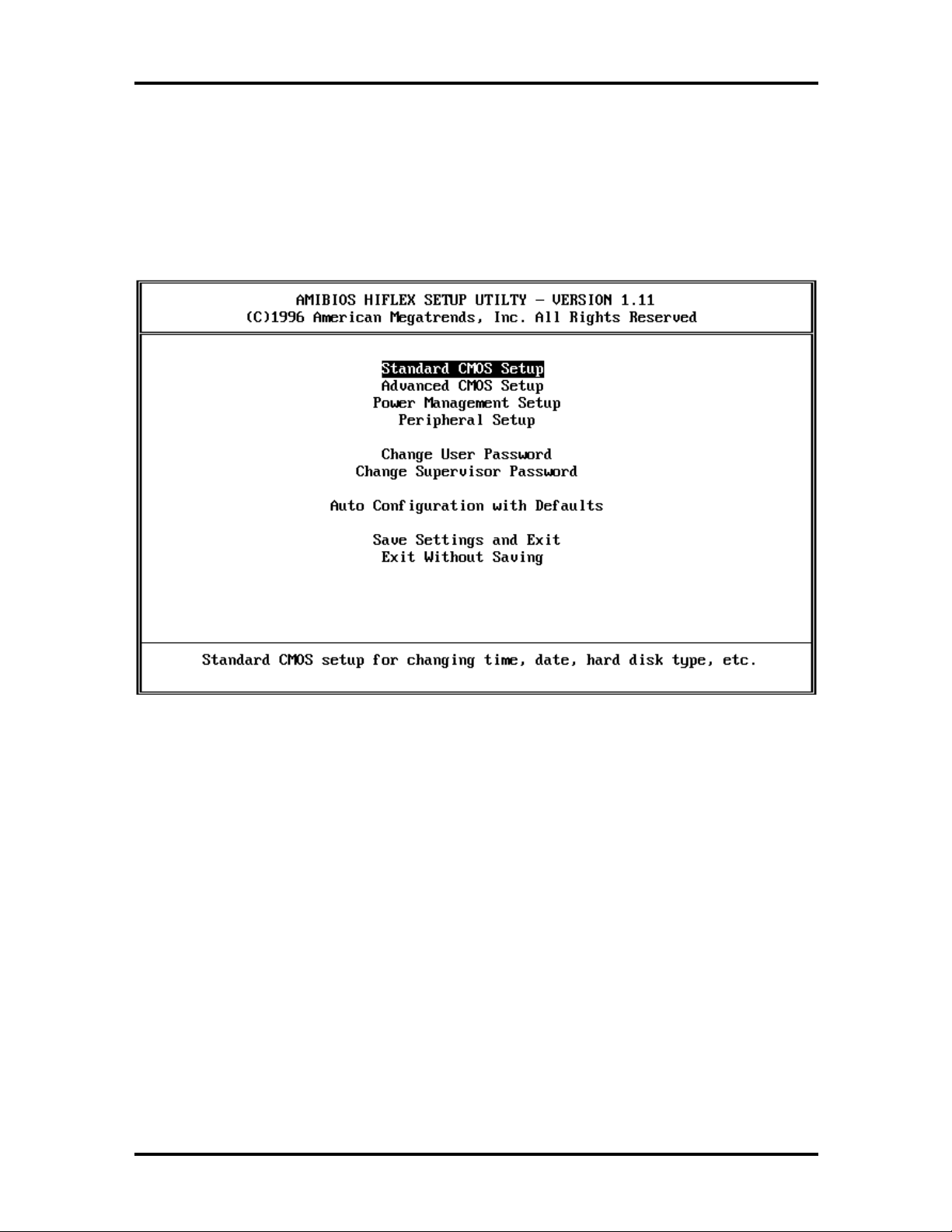
1-17 The AMIBIOS Setup Utility Menu.................................................................1-19
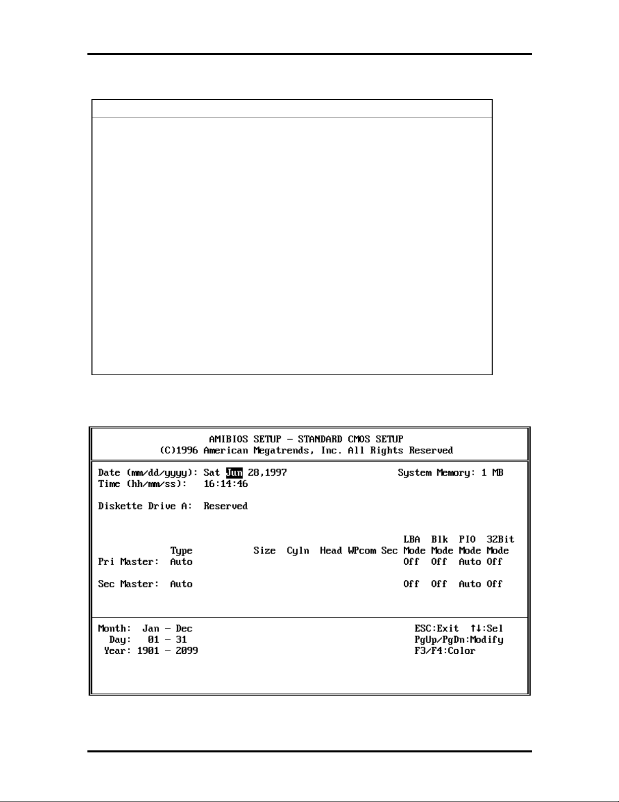
1-18 The Standard CMOS Setup Menu..................................................................1-20
1-19 The Advanced CMOS Setup Menu ................................................................1-22
1-20 The Power Management Setup Menu.............................................................1-24
1-21 The Peripheral Setup Menu............................................................................1-26
Page 8

Contents vii
3-1 Functional Block Diagram..............................................................................3-2
5-1 Disconnecting the Hard Drive Assembly.........................................................5-5
5-2 Cover screw locations....................................................................................5-8
5-3 Memory module notch locations.....................................................................5-8
5-4 Memory module sockets ................................................................................5-9
5-5 Locating the palm rest screws ........................................................................5-11
5-6 Two dip switch banks.....................................................................................5-11
5-7 One dip switch bank.......................................................................................5-12
5-8 Factory default switch settings (SW50) ..........................................................5-12
5-9 Factory default switch settings (SW52) ..........................................................5-13
5-10 The LED Board Module Assembly.................................................................5-16
5-11 The Electronic Module Assembly...................................................................5-17
5-12 NEC Versa 2700 Series Illustrated Parts Breakdown......................................5-20
List of Tables
1-1 Model Configurations ....................................................................................1-1
1-2 Feature Highlights..........................................................................................1-3
1-3 Fn Key Combination Summary.......................................................................1-9
1-4 Hot Keys Supported by the External Keyboard ..............................................1-9
1-5 Setup Utility Menu.........................................................................................1-20
1-6 Standard CMOS Setup Menu.........................................................................1-21
1-7 Advanced CMOS Setup Menu .......................................................................1-23
1-8 Power Management Setup Menu....................................................................1-24
1-9 Peripheral Setup Menu...................................................................................1-27
1-10 16-MB Memory Configurations .....................................................................1-28
1-11 32-MB Memory Configurations .....................................................................1-28
1-12 64-MB Memory Configurations .....................................................................1-28
2-1 NEC Versa 2700 Series Specifications ...........................................................2-1
2-2 System Board Specifications ..........................................................................2-5
2-3 DC Converter Board Specifications................................................................ 2-7
2-4 LED Indicator Board Specifications...............................................................2-9
2-5 I/O Board Specifications ................................................................................2-9
2-6 LCD Inverter Board Specifications................................................................. 2-10
2-7 Status LED Descriptions................................................................................2-11
2-8 Diskette Drive Specifications..........................................................................2-11
Page 9

viii Contents
2-9 Hard Disk Drive Specifications.......................................................................2-12
2-10 CD-ROM Reader Specifications.....................................................................2-12
2-11 Battery Specifications.....................................................................................2-12
2-12 DC/DC Converter and Battery Charger Specifications....................................2-13
2-13 Battery Charger Specifications .......................................................................2-13
2-14 Keyboard Specifications.................................................................................2-14
2-15 AC/DC Adapter Specifications.......................................................................2-14
2-16 LCD/LED Board Specifications .....................................................................2-15
2-17 BIOS Specifications.......................................................................................2-16
2-18 Power Management Modes............................................................................2-17
2-19 Power Status of Local Devices.......................................................................2-18
2-20 Mode Definitions ...........................................................................................2-19
2-21 Hot Keys........................................................................................................2-19
2-22 External Hot Keys..........................................................................................2-20
2-23 Environmental Specifications..........................................................................2-20
2-24 Power Specifications......................................................................................2-20
2-25 Vibration Specifications .................................................................................2-21
2-26 Shock Specifications......................................................................................2-21
2-27 Electro-Static Discharge Specifications ..........................................................2-21
4-1 NECCSD Service and Information Telephone Numbers .................................4-1
4-2 POST Error Messages....................................................................................4-4
4-3 Beep Codes....................................................................................................4-7
4-4 BIOS Informational Messages........................................................................4-8
4-5 Run-time Error Messages...............................................................................4-9
4-6 Quick Troubleshooting...................................................................................4-10
5-1 16-MB Memory Configurations .....................................................................5-7
5-2 32-MB Memory Configurations .....................................................................5-7
5-3 64-MB Memory Configurations .....................................................................5-7
5-4 NEC Versa 2700 Series Field-Replaceable Parts.............................................5-18
5-5 Packaging and Documentation Part Numbers.................................................5-21
Page 10

Section 1
Technical Information
This section focuses on describing features and operations of the NEC Versa 2700 Series
notebook computer, including the BIOS Setup program. (Refer to the user’s guide for more
information on operating the notebook.) The NEC Versa 2700 Series notebooks are lightweight, compact, and fully IBM compatible.
The NEC Versa 2700 Series notebook comes in the following model configurations.
Table 1-1 Model Configurations*
Configuration Versa 2730M
Versa 2730MT
CPU
L2 Cache
On-Board
Memory
SO-DIMM
Memory
Video Memory
LCD - Unit
Intel™ P55C 133MHz (MMX)
256 KB 256 KB 256 KB or 512 KB
None None None
16 MB 16 MB 16 MB or 32 MB
None None None
Versa 2730M
12.1” DSTN SVGA
EDMGR68KCF /
Panasonic
Versa 2730MT
12.1” TFT SVGA
NL80060BC31-02 /
NEC
Versa 2750MT
Versa 2760MT
Versa 2750MT
Intel P55C 150MHz (MMX)
Versa 2760MT
Intel P55C 166MHz (MMX)
12.1” TFT SVGA
NL80060BC31-02 /
NEC
Versa 2770MT
Versa 2780MT
Versa 2770MT
Intel P55C 200MHz (MMX)
Versa 2780MT
Intel P55C 233MHz (MMX)
12.1” TFT SVGA
NL80060BC31-02 /
NEC
Hard Disk Drive
Diskette Drive
1.44 GB
MK1403MAV/
Toshiba
3.5” (3 mode)
FD1238T-002 /
NEC
2.10 GB
DK225A-21/Hitachi
3.5” (3 mode)
FD1238T-002 /
NEC
2.10 GB
DK225A-21/Hitachi
3.5” (3 mode)
FD1238T-002 /
NEC
Page 11

1-2 Technical Information
y
y
y
y
Table 1-1 Model Configurations* (cont'd)
Configuration Versa 2730M
Versa 2730MT
CD-ROM
Keyboard Unit
Pointing Device
PCMCIA
EEP / ECP
Parallel Port
Serial Port
VGA Port
PS/2 Port
DC-In Jack
Fax/Modem
(USA, JP, and
Aus. Only)
16X
CD-316E / TEAC
85 Ke
(Windows
US, UK, GR, FR/
ALPS
Touchpad
KGDDDH/ALPS
2 x T
1 x Type III
Yes Yes Yes
Yes Yes Yes
Yes Yes Yes
Yes Yes Yes
Yes Yes Yes
56 K, SW DSVD/
Venus
s
®
pe II/
95)
Versa 2750MT
Versa 2760MT
16X
CD-316E / TEAC
85 Ke
(Windows 95) US,
UK, GR, FR/ ALPS
Touchpad
KGDDDH/ALPS
2 x Type II/
1 x Type III
56 K, SW DSVD/
Venus
s
Versa 2770MT
Versa 2780MT
20X
CD-220E / TEAC
85 Ke
(Windows 95) US,
UK, GR, FR/ ALPS
Touchpad
KGDDDH/ALPS
2 x Type II/
1 x Type III
56 K, SW DSVD/
Venus
s
Audio Port
FIR Port
USB Port
Expansion Port
Battery Pack
AC Adapter
Power Cord
*NEC also ships a 150 MMX DSTN model outside of the U.S.
Yes Yes Yes
Yes Yes Yes
Yes Yes Yes
Yes Yes Yes
NiMH (3300 mAh)
8HR-4/3AU-YZN/
Sanyo
45 W
ADP52 /
Astec or Liteon
US/UK/Aus/Ger/JP US/UK/Aus/Ger/JP US/UK/Aus/Ger/JP
Li-Ion (2600 mAh)
4UR18650-2-YZN/
Sanyo
45 W
ADP52 /
Astec or Liteon
Li-Ion (2600 mAh)
4UR18650-2-YZN/
Sanyo
45 W
ADP52 /
Astec or Liteon
Page 12
Technical Information 1-3
g
y
g
y
y
y
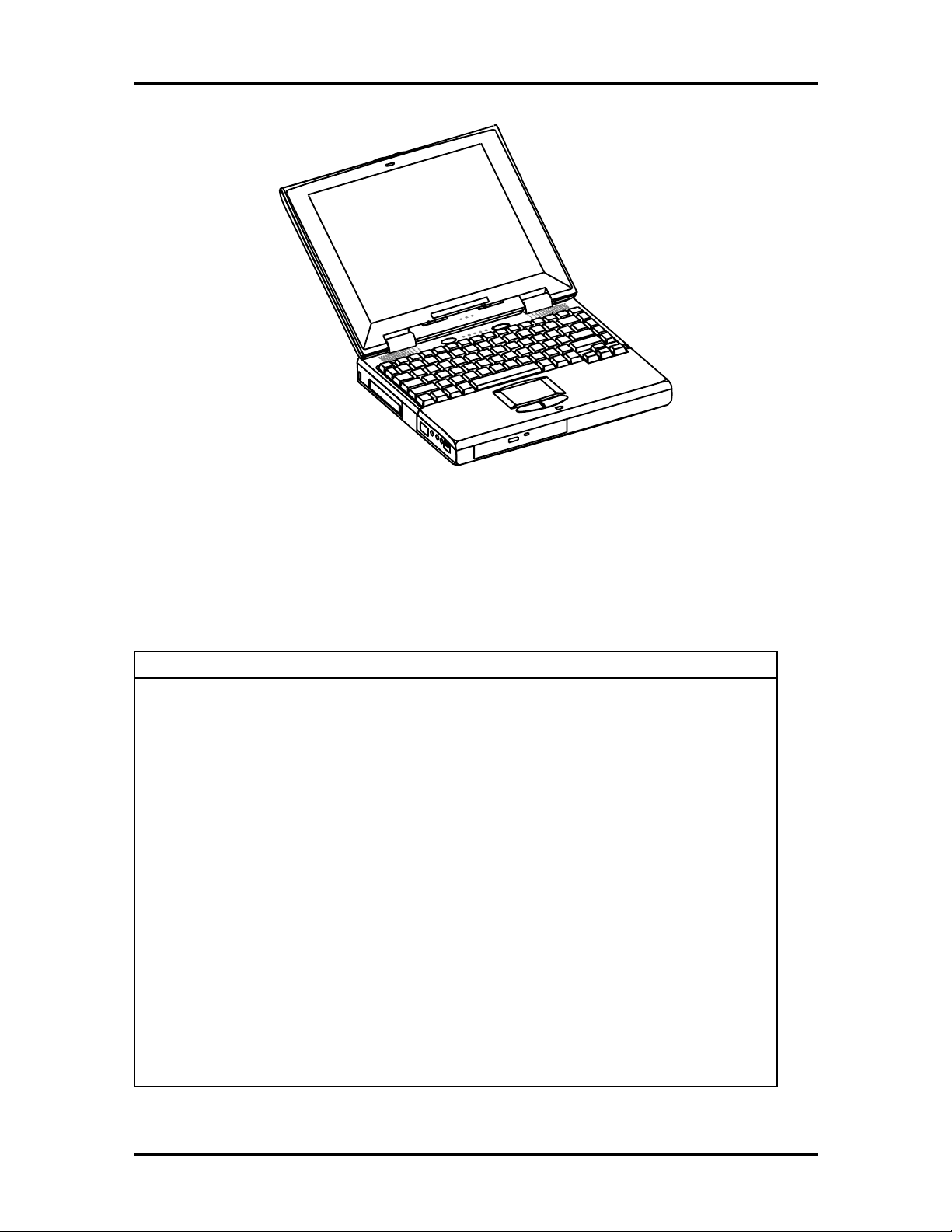
Figure 1-1 NEC Versa 2700 Series Notebook
FEATURE HIGHLIGHTS
The NEC Versa 2700 Series notebook includes a variety of innovative features designed to
meet the most demanding computing requirements.
Table 1-2 Feature Highlights
Features Description
CPU
SO-DIMM
Memory
Cache RAM
Display
VGA Chip
HDD
Intel P55C-133/150/166/200/233 MHz MMX processor with internal
32 KB cache memory and math coprocessor
16 MB, 32-MB, or 64-MB of SO-DIMM RAM, can be up
MB
256 KB/512 KB (Versa 2770MT/Versa 2780MT), L2 cache
12.1” DSTN or 12.1” TFT VGA Color LCD at 800 x 600 pixels
resolution with 64K colors
2 MB DRAM, 24-bit true-color RAMDAC, Graphics/Video
Accelerator, Dual clock s
Buffer Data Strippin
32-bit compliance interface
Removable 2.5-inch IDE high-capacity hard drive (12.7 mm height)
nthesizer, ZV (Zoomed Video) port, Z-
, PCI Bus Mastering, and a high-speed glueless
raded to 128
FDD
Keyboard
Built-in 3.5-inch,1.44 MB diskette drive
Built-in 85-ke
embedded numeric ke
dedicated screen control ke
enhanced 85-key compatible keyboard
keyboard with 12 programmable function keys,
pad and special function control keys,
s, and inverted “T” cursor keys/IBM
Page 13

1-4 Technical Information
y
y
g
Table 1-2 Feature Highlights (cont'd)
Features Description
Pointing Device
PC Card Slots
I/O Ports
Audio System
Power System
VersaGlide Touchpad
Two slots that support two T
Type III
1 x Serial Port (w/ FIFO)/1 x Printer Port (ECP/EPP)/1 x VGA Port/
1 x PS/2 ke
Port/1 x Infrared Port
Headphones, Line-In, Microphone, and manual volume control/
built-in stereo speakers and woofer
Auto-switchin
Li-Ion Battery pack / Advanced power management capabilities
board & mouse port/1 x Modem Port/1 x Expansion
AC Adapter (100V - 240V) / Rechargeable NiMH or
pe II PC cards at the same time, or one
Page 14
Technical Information 1-5
SYSTEM CONFIGURATION
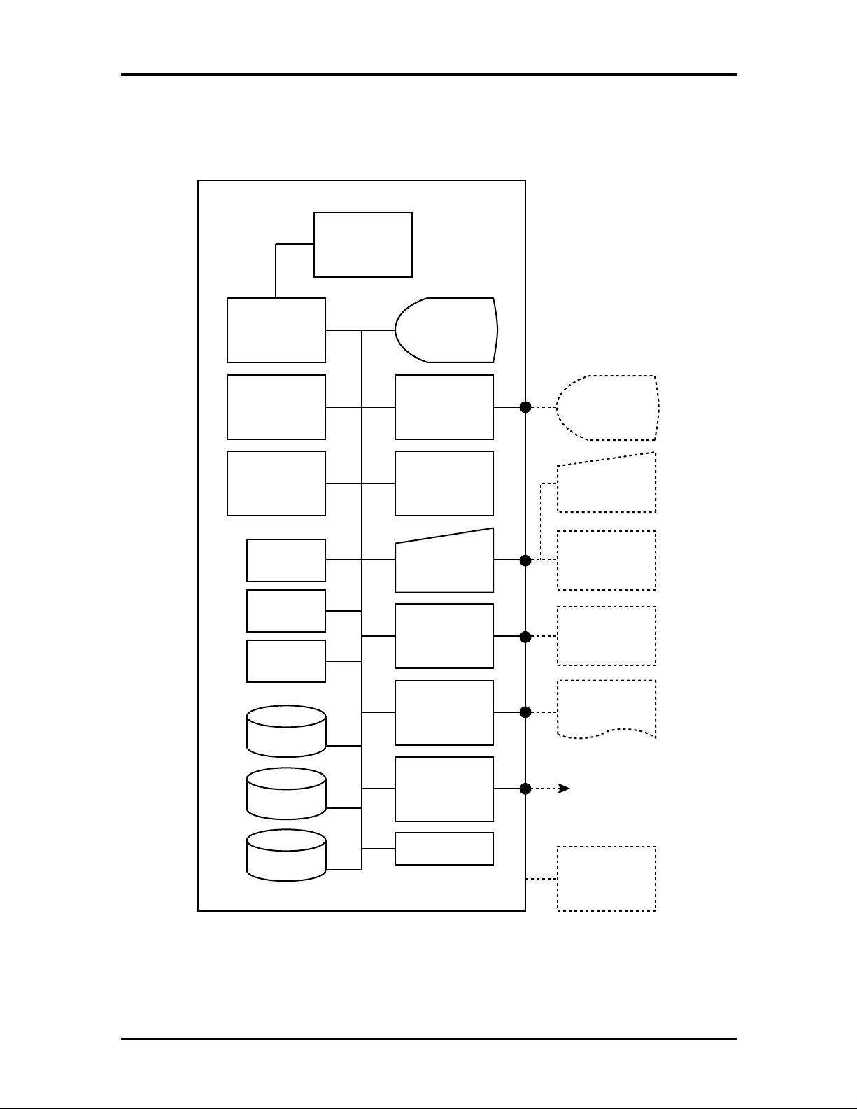
The following diagram shows the NEC Versa 2700 Series system configuration.
Pentium P54C,
P55C, or Tillamook
Support (TCP)
CPU
Cache RAM
L2: 256KB or
512KB
Versa 2770MT/
(
Versa 2780MT)
BIOS
Flash ROM
Bank 2 (Slot 2)
16/32/64MG
So-DIMM
Bank 1 (Slot 1)
16/32/64 MB
soDIMM
Fax/Modem
Audio
CD ROM
Color LCD
(800x600)
DSTN and TFT
PCI Bus
Controller
(VGA)
NEC VersaGlide
Keyboard
Serial Interface
(RS-232)
Parallel
Interface
External VGA
Monitor
PS/2 Keyboard
and
PS/2 Mouse
RS-232C
Peripheral
Printer
Removable HDD
3.5" FDD
PCMCIA Card
Slot x 2
Battery Pack
PCMCIA Card
FIR/IR
Figure 1-2 System Configuration Diagram
Page 15
1-6 Technical Information
QUICK TOUR OF THE NOTEBOOK
Take a moment to become familiar with the locations and functions of all controls. It is recommended that you first go through the notebook’s user guide for more information on
how to operate all of the features.
Main Components
This section describes the main features of the NEC Versa 2700 Series computer.
Color LCD Display Panel
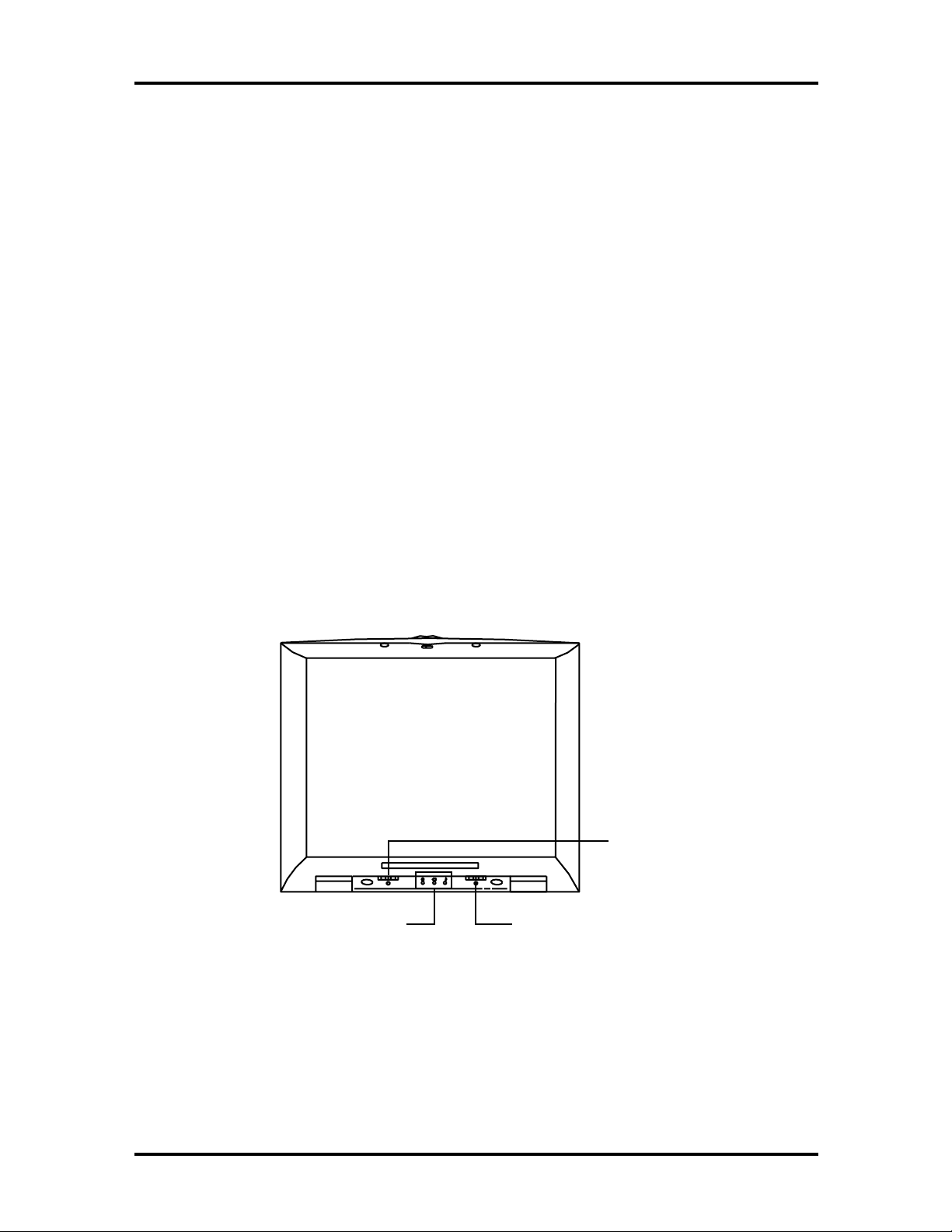
The notebook has either a built-in 12.1-inch passive-matrix dual scan DSTN or a 12.1-inch
active-matrix TFT color liquid crystal display (LCD) which you can adjust and tilt to your
desired viewing position. The LCD provides 800x600 pixel resolution with a maximum of
256 K colors, and supports simultaneous display with an external VGA monitor. The system also supports view panning when the resolution of the CRT is greater than 800 x 600.
The LCD screen also uses Cold Cathode Fluorescent Tube (CCFT) backlighting which consumes most of the power from the notebook. To save battery power, the system has an advanced power management feature that powers down the LCD when it has not been used
for a predetermined amount of time. You can adjust the brightness and contrast level of the
LCD by using the slide bars under the LCD panel on the front of the system.
Power and Suspend
Status LEDs
Figure 1-3 LCD Panel
Contrast
Control
Brightness
Control
Page 16
Technical Information 1-7
Power Button/LCD Cover Switch
The power button, when pressed, turns on the notebook’s power. Press it again to turn
computer power off. Whenever the notebook is in “save-to-file” suspend mode, the power
button serves as a manual resume switch, allowing you to continue your application work
where you left off.
NOTE
turning off and turning on the power.
:
Always wait for a few seconds between
The LCD cover switch is connected to the right hinge of the LCD Assembly. This switch
automatically depresses and releases when you lower or raise the LCD display panel. Depending on your power management settings, this switch either converts the notebook to
the Suspend mode or shuts off the LCD when you close the cover.
Status Panel and Power Indicator
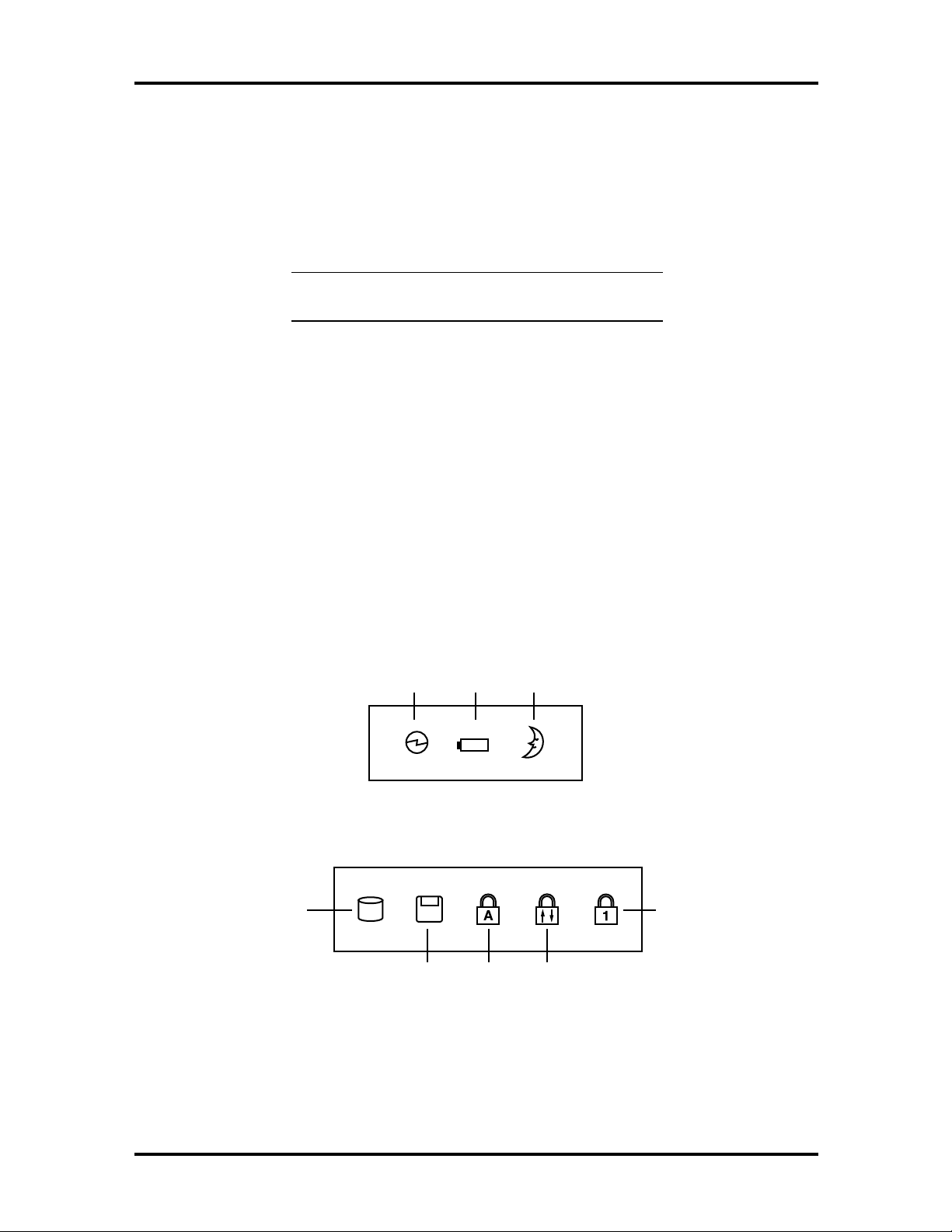
Directly below the LCD display, in the center, is the System Status LED panel. These
LED’s provide an easy way to determine the current power mode of the unit. Below these
two LED’s, on the system unit display, is a row of five (5) more. These LED’s light to indicate whether a device is being accessed, an operation is being done, or if a certain mode is
or has been activated.
Power
LED
Battery
Charging
LED
Suspend
Mode
LED
Figure 1-4 System Status LED Panel
Hard Drive
Access
Access
Caps
Lock
Scroll LockDiskette Drive
Figure 1-5 Device Status LED Panel
Num
Lock
Page 17
1-8 Technical Information
Keyboard
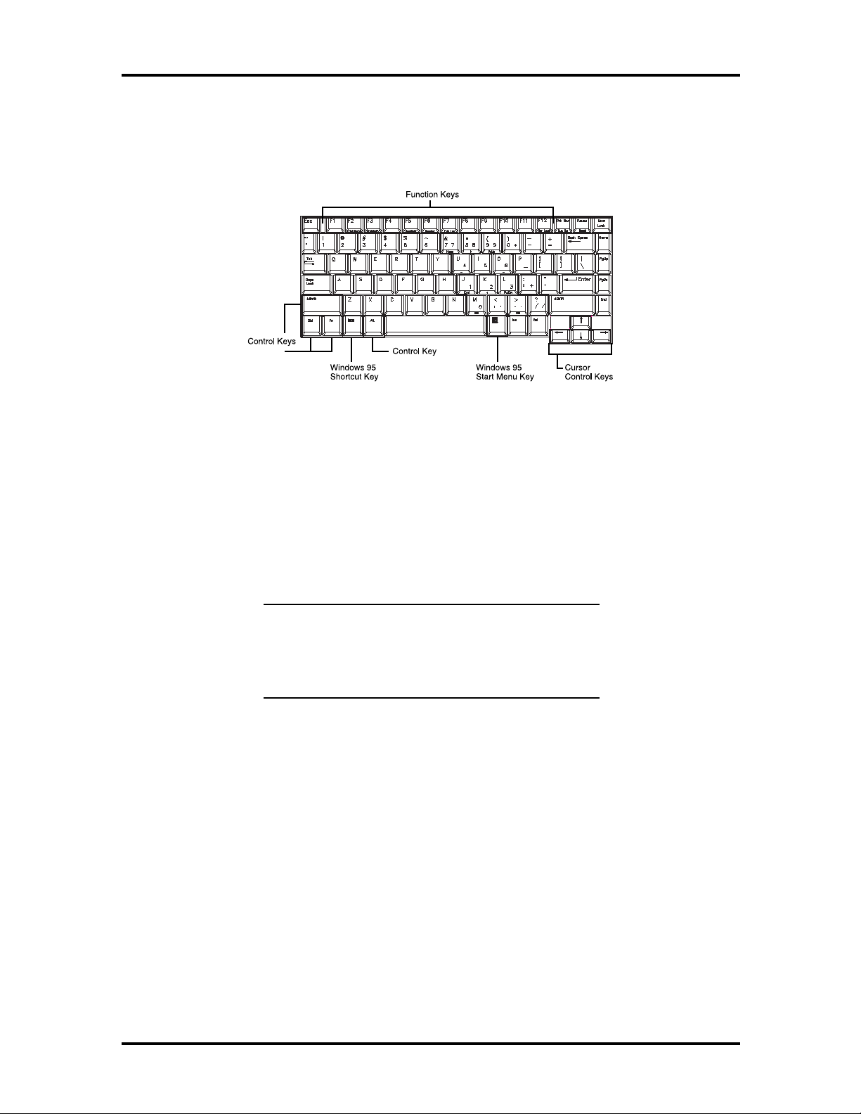
The notebook has a built-in 85-key keyboard that provides complete emulation of a fullsized IBM AT-enhanced keyboard with function keys and screen/cursor control keys.
Figure 1-6 Standard Keyboard Layout
The notebook’s keyboard also includes an embedded numeric keypad, and some special
function keys that are activated by pressing the Fn key together with another key. These
special function keys (more popularly known as “hot keys”) allow you to control and adjust
some of the notebook’s functions like; display controls, speaker volume, and power management features. The embedded numeric keypad is activated by pressing the
key. Once the
Num Lock
key is pressed, the upper blue symbols become active.
Num Lock
NOTE
ables the alphanumeric keys where the embedded
keys are located. Press the
disable the embedded keys and resume normal keyboard operation.
:
Activating the
Num Lock
Num Lock
key in turn dis-
key again to
Page 18

Table 1-3 Fn Key Combination Summary
y
y
y
y
y
y
y
y
g
y
y
Key Combination Function
Technical Information 1-9
Fn
key + F2 key
Fn key +
Fn
key + F4 key
Fn
key + F5 key
Fn
key + F6 key
Fn
key + F7 key
Fn
key +
Fn
key +
key
Fn
key + Suspend
Button
Power Switch +
Suspend Button
F3
key
F12
key
Left Ctrl
This key combination toggles the highlight of DOS text.
This ke
LCD displa
of LCD and CRT.
This key combination puts the system in Standby mode.
This ke
between standard and full.
This ke
High volume.
This key combination selects the desired P/M level.
This key combination enables the Scroll Lock function.
This key combination simulates the right Ctrl key functions.
This key combination enables Save-to-Disk on demand.
This key combination forces the power off.
combination toggles between video display output to the
, to an external CRT monitor, to a simultaneous displa
combination toggles the LCD display backlighting (CCFT)
combination sets the system speakers to Low, Medium, or
Table 1-4 Hot Keys Supported by the External Keyboard
External Keyboard
Combination
Ctrl
key
Ctrl
key
Ctrl
key
Ctrl
key
Ctrl
key
key +
key +
key +
key +
key +
Alt
Alt
Alt
Alt
Alt
key +
key +
key +
key +
key +
F2
F3
F5
F6
F7
Function
This key combination toggles the highlight of DOS text.
This ke
the LCD displa
simultaneous display of LCD and CRT.
This ke
(CCFT) between standard or full.
This ke
Medium, or High volume.
This ke
level.
combination toggles between video display output to
, to an external CRT monitor, or to a
combination toggles the LCD display backlightin
combination sets the system speakers to Low,
combination selects the desired power management
Page 19
1-10 Technical Information
The notebook’s keyboard also features an embedded editing keypad, which offers an optional method for editing and moving within documents. The embedded editing keys are
color coded in blue and embedded on the front side of the embedded numeric keypads. To
use these editing keys, first press the
Num Lock
key and then combine the
key and the
Shift
desired function key to enable these editing keys. When the embedded editing keys are operational, the Num Lock LED will be activated. To return to normal keyboard operation,
press the
VersaGlide
Num Lock
key again.
NOTE:
bedded numeric key pads are activated.
When the Num Lock LED glows the em-
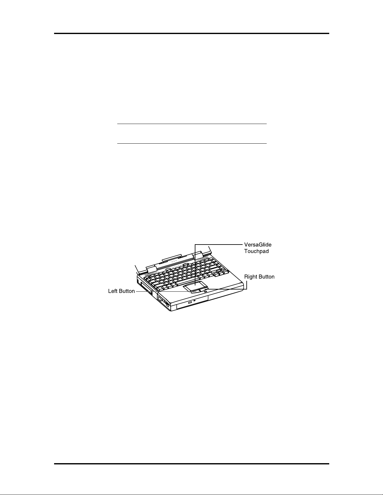
In front of the keyboard panel, in the center of the palm rest typing surface, is the VersaGlide pointing device. The buttons below the touchpad are configured (by default) as the
left and right button, respectively. The left button is configured as the left mouse button.
The right button is configured as the right mouse button. Moving the pointer on the screen
is done by moving your finger over the surface and directing the pointer where you want it
to go. The touchpad also supports single and double tap capabilities that mimic the left
button.
Figure 1-7 VersaGlide
Under the Palm Rest in Front of the Notebook
This section describes the features on the front side of the NEC Versa 2700 Series computer.
Hard Disk Drive
The notebook’s internal hard drive is under the palm rest on the right side. The NEC Versa
2700 Series provides an industry standard 2.5-inch, 1.4-GB or 2.1-GB IDE hard disk drive,
upgradeable to 3 GB or 4GB. The system BIOS also includes Auto IDE detection and LBA
mode for easy installation as well as later upgrades for higher capacity disk drives.
Page 20
Technical Information 1-11
Memory Module Compartment
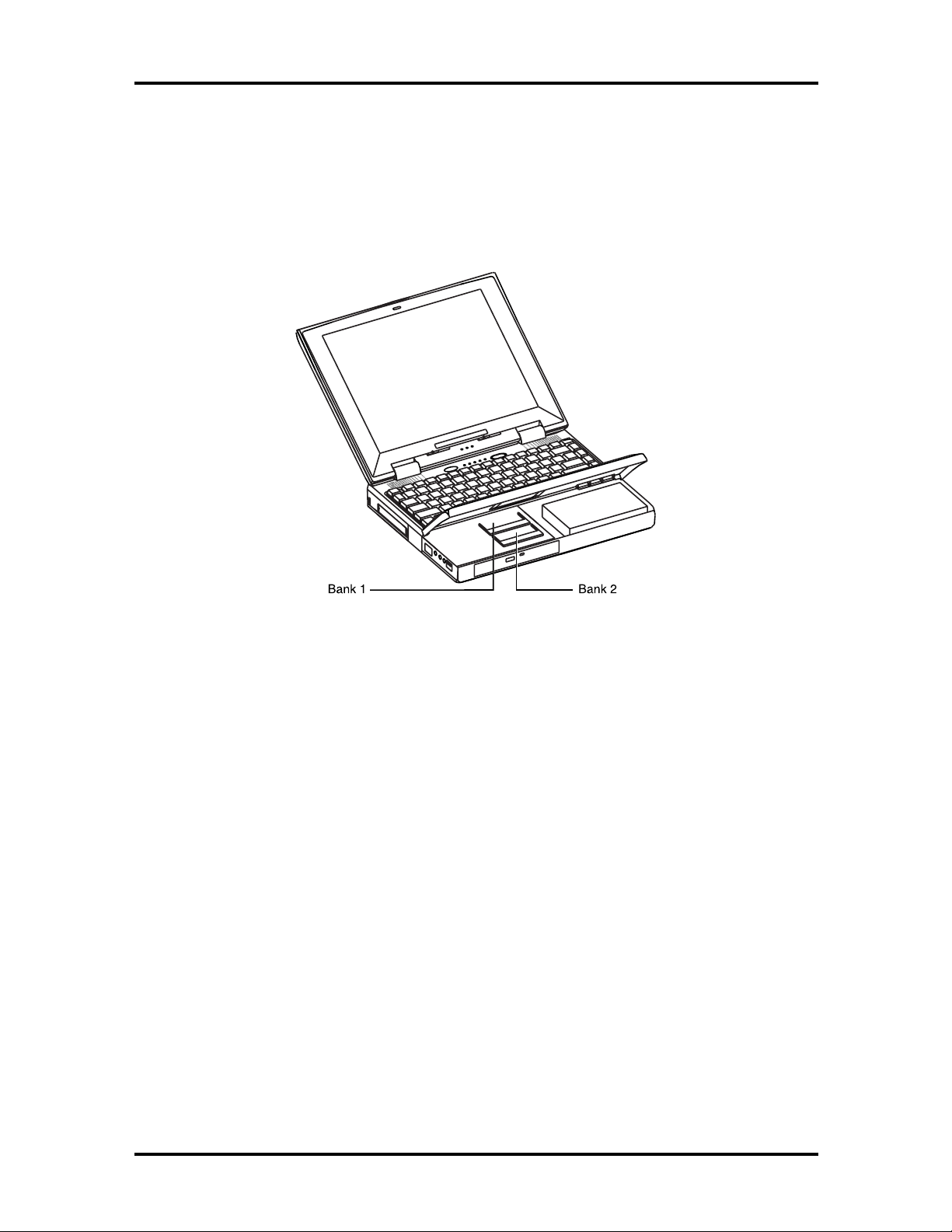
The memory compartment is located under the palm rest. Inside the compartment are two
memory module sockets (Bank 1 and Bank 2) that can accommodate 16-/32-/64-MB SODIMM modules. Bank 1 accepts 1.75-inch modules as well as 1-inch modules; Bank 2 only
accepts standard 1-inch modules.
Figure 1-8 Memory Module Sockets
Right Side of the Notebook
This section describes the features on the right side of the NEC Versa 2700 computer.
Non-Removable Floppy Disk Drive
The disk drive, which supports 3.5-inch 1.44-MB high-density (HD) diskettes or 720 KB
double-sided (DS) diskettes is on the right-front side of the notebook. Insert the diskette
with the metal shutter towards the drive and the diskette label facing up. To remove the
diskette, press the Eject button found on the upper right of the diskette drive.
Battery Compartment
The battery compartment is on the right side bottom rear of the notebook. It houses the rechargeable NiMH battery pack or Li-Ion battery pack. The battery pack begins charging
whenever you connect the AC adapter to the notebook. It is very important to always have
the battery installed on the notebook and to have it always charged. Leaving the battery
pack out of the unit for a long period of time completely drains the battery cells.
Page 21
1-12 Technical Information
NOTE:
Type A battery packs with 3300mAh (NiMH) or
2600mAh (Li-Ion).
The NEC Versa 2700 Series models use
DC-IN Connector Jack
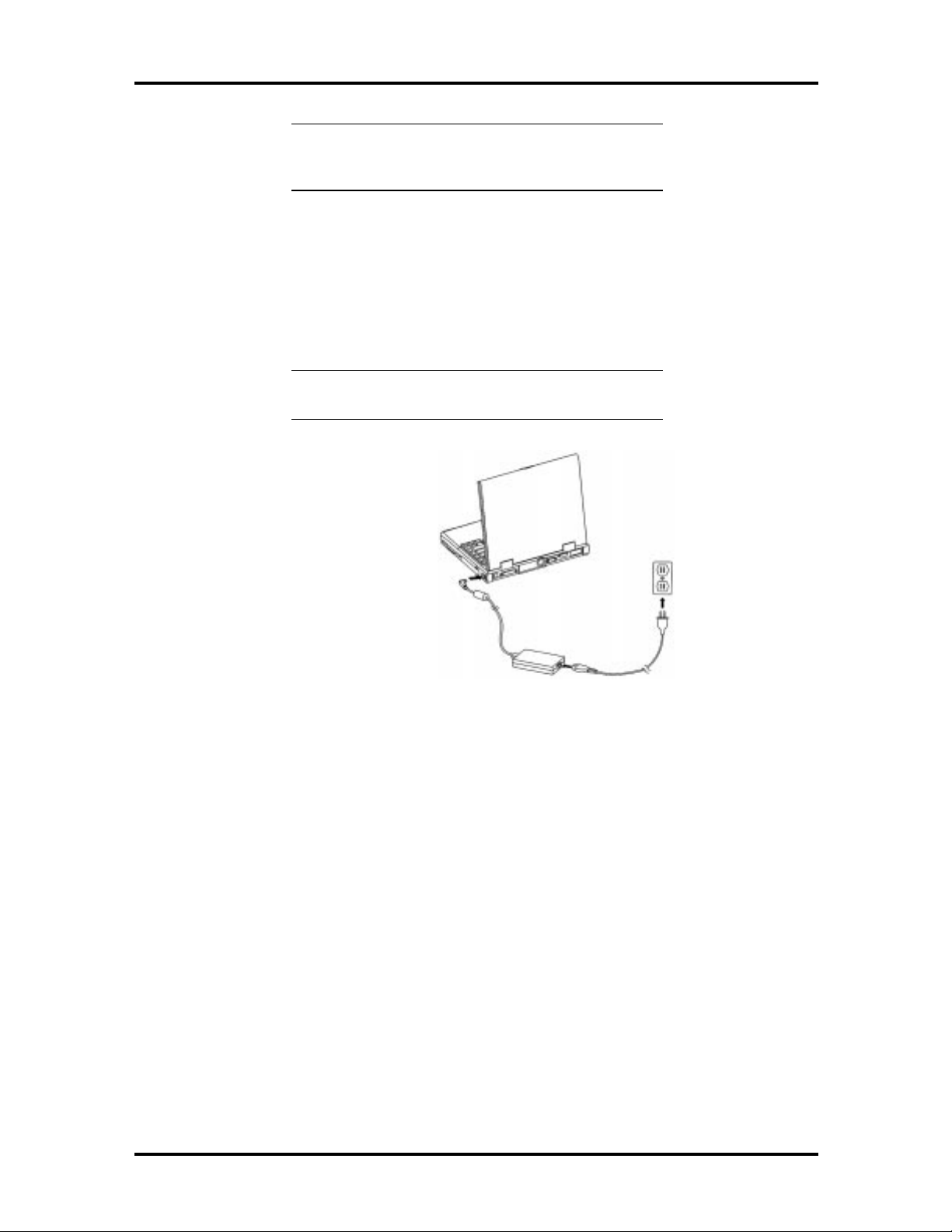
The NEC Versa 2700 series provides an universal auto-switching AC adapter which connects the AC power cord into the power outlet. It is important to have the AC adapter connected to the notebook to recharge the battery and keep the notebook working
continuously.
NOTE:
the NEC Versa 2700 Series notebook.
Use only the AC adapter that comes with
Figure 1-9 Connecting the AC Adapter to the Notebook
Page 22
Technical Information 1-13
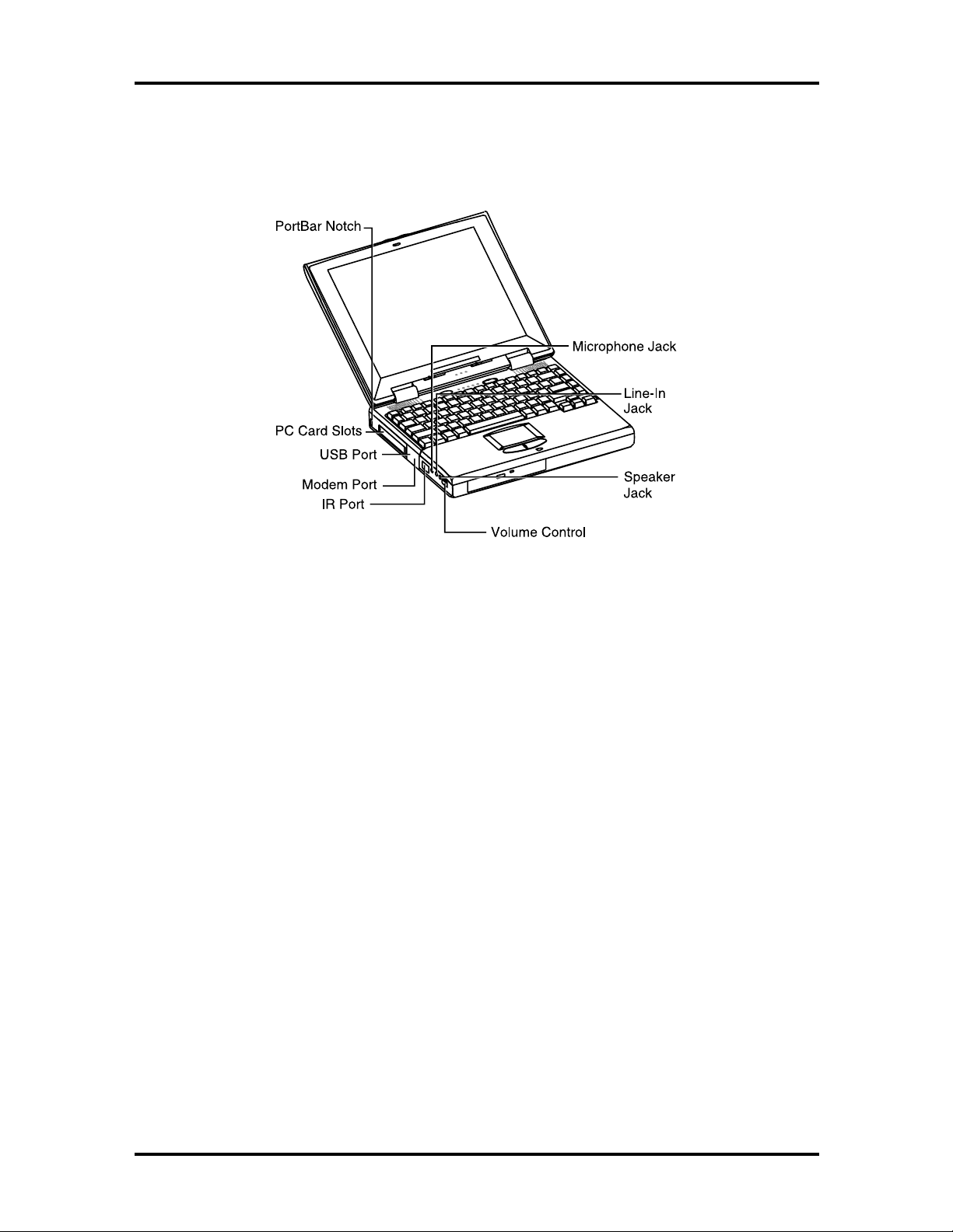
Left Side of the Notebook
The following details the left side of the NEC Versa 2700 Series computer.
Figure 1-10 Left Side of the Notebook
PC Card Slot Compartment
The compartment houses two card slots that support two Type II devices, or one Type III
device. Open the compartment door to view the PC card slots. Insert Type III cards into the
lower slot. Insert the card with the pin sockets facing towards the drive and the label facing
up. Once the card is inserted, pivot the eject button (which pops out) to the side. To remove the PC card, pivot the eject button out, then push on the Eject button to release the
pin connections. Slowly pull out the card.
The NEC Versa 2700 Series also comes with DOS/Windows PC card drivers for supporting
various PC cards like modem cards, network cards, and other I/O and memory cards. The
upper PC card slot is referred to as “Slot 0” while the bottom slot is referred to as “Slot 1.”
Slot 0 always takes precedence over Slot 1 in drive designations.
Page 23
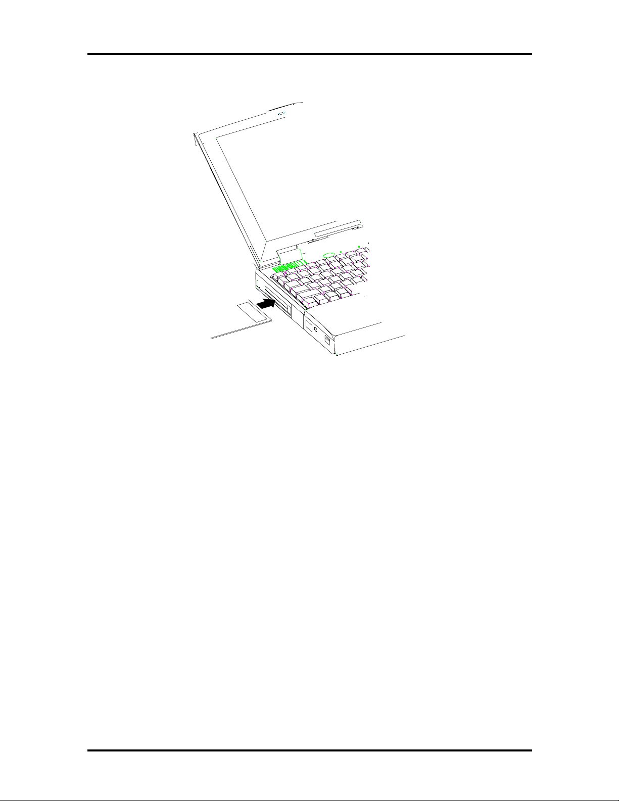
1-14 Technical Information
Figure 1-11 Inserting a PC Card
The USB Connector
The USB is a cable bus that supports data exchange between a host computer and a wide
range of simultaneously accessible peripherals. The attached peripherals share USB bandwidth through a host scheduled token based protocol. The bus allows peripherals to be attached, configured, used, and detached while the host and other peripherals are in
operation. This is referred to as dynamic (or hot) attachment and removal.
The FIR Window
This window allows wireless communication with any IrDA compliant device (such as another IrDA computer or printer) without the use of a cord or cable. This port transmits up
to 4 M bits per second.
The Audio Jacks and Thumbwheel Volume Control
Microphone Jack — Connects to an external microphone.
Line-In Jack — Connects to a line-in device such as a synthesizer, stereo Walkman, or an
audio CD player.
Headphones — Connects to headphones or amplified speakers.
Page 24
Technical Information 1-15
Thumbwheel Volume Control — Allows the user to precisely adjust the sound volume.
The Fax/Modem
All models of the system feature a built-in (56Kbps capable, K56 felx compliant)
fax/modem freeing the PC card slots for other uses.
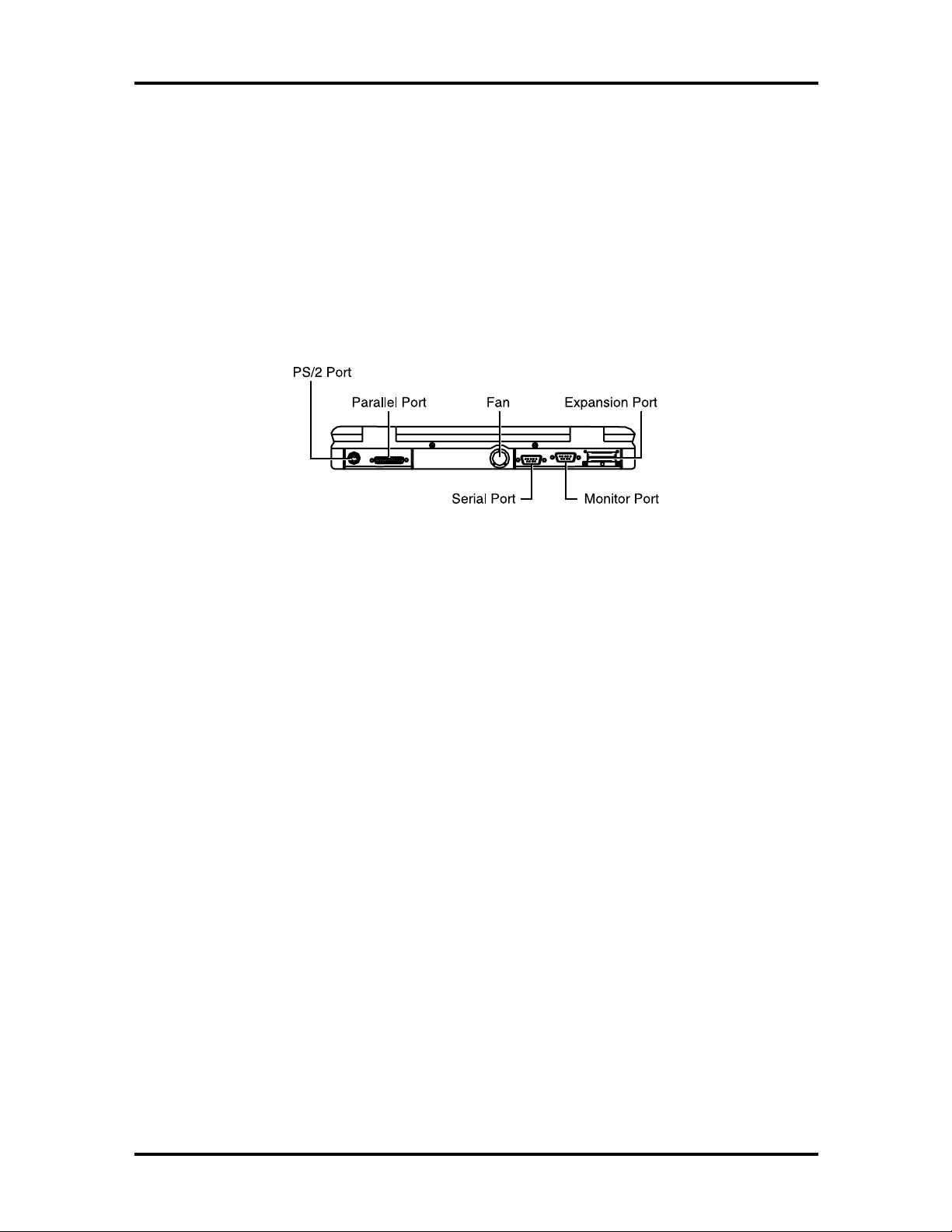
Rear of the Notebook
The following details the rear side of the NEC Versa 2700 Series computer.
Figure 1-12 Rear Side of the Notebook
External Keyboard and PS/2 Mouse Port
The external keyboard and PS/2 mouse port allows you to connect an external full-sized
IBM AT-enhanced keyboard or a PS/2 mouse. When an external keyboard is connected,
both the built-in keyboard of the notebook and the external keyboard can be used simultaneously.
The NEC Versa 2700 Series also accepts an optional Y-connector adapter allowing simultaneous use of an external AT-enhanced keyboard and a PS/2 mouse. When using DOS or
Windows for Workgroups, if an external serial mouse is installed, the VersaGlide is not
supported.
Page 25
1-16 Technical Information
Figure 1-13 Connecting an External Keyboard and PS/2 Mouse
VGA Port
The 15-pin female VGA connector allows you to connect an external VGA monitor that
supports up to 1024x768 pixels resolution. When displaying on an external VGA monitor
alone, the VGA port supports resolutions up to 1024x768 at 64K colors.
The NEC Versa 2700 Series provides a VGA VESA driver file set for installing different
display resolution drivers for Windows Setup. These are on the Product Recovery CD You
can also toggle the display between the LCD and the external monitor by pressing
Fn F10
key combination.
NOTE:
nal monitor only shows 800x600 resolution, if the
computer is running with Simultaneous display, but
the screen image size is reduced. This enables the
image to be panned around the screen if wanted.
Toggle the display to the external monitor only in order to display a full screen image.
Refer to Appendix A for a list of supported video
modes.
When set to 1024x768 resolution, the exter-
Page 26
Technical Information 1-17
Figure 1-14 Connecting an External Monitor
Printer Port
The 25-pin printer port provides a parallel interface to connect a parallel printer or pocket
network adapter. Many operating systems and software applications refer to this port as
LPT1.
Figure 1-15 Connecting to the Printer Port
Serial Port (COM1)
The 9-pin serial port provides a serial interface for a RS-232C device such as external serial
modem. This port is commonly referred to as COM1.
Page 27

1-18 Technical Information
Figure 1-16 Connecting to the Serial Port
NOTE
ing an external parallel or serial device. After turning
on the power again, run the BIOS Setup program if
needed.
:
First power off the system before connect-
SYSTEM BIOS SETUP PROGRAM
This section provides the features and operation of the AMIBIOS Setup program used in
the NEC Versa 2700 Series. The BIOS (Basic Input-Output System) Setup program lets
you change the system configuration settings such as the current date and time, port settings, and power management.
The screens and tables show the basic type of information but may not depict the latest avialable BIOS settings.
As POST (Power-On Self Test) executes during boot up process, the screen displays the
following message:
Press F2 to Enter SETUP
Press F2 to run the BIOS Setup program. The BIOS Setup program is organized into five
(5) pages of menus. Select the menu you want to change, then press
one option to another, you use the ↑ and ↓ keys while using
settings. To return to the initial menu, press
Esc
.
PgUp
and
. To move from
Enter
to modify the
PgDn
To exit the BIOS Setup program, move the cursor down (on the Setup Utility page) to
either
Save Settings and Exit
or
Exit Without Saving
and press
Enter
.
Page 28
Technical Information 1-19
THE BOOT SETUP MENU
The AMIBIOS Setup Utility menu allows you to select one of the following menus: Standard CMOS Setup, Advanced CMOS Setup, Power Management Setup, or Peripheral
Setup. You can also load Default Configurations as well as select to use (or change) the
Supervisor and/or User Password from this menu.
Figure 1-17 The AMIBIOS Setup Utility Menu
Page 29
1-20 Technical Information
Item Function
Table 1-5 Setup Utility Menu
Standard CMOS
Setup
Advanced CMOS
Setup
Power Management
Setup
Peripheral Setup
Change Supervisor
Password
Auto Configuration
with Defaults
Save Settings and
Exit
Exit Without Saving This option exits CMOS Utility setup without saving any of
Pressing
menu.
Pressing
menu.
Pressing
menu.
Pressing
This option allows you to set the Supervisor Password.
This option allows you to set the system defaults.
This option exits CMOS Utility setup and saves all changes.
your changes.
Enter
directs you to the Standard CMOS Setup
Enter
directs you to the Advanced CMOS Setup
Enter
directs you to the Power Management Setup
Enter
directs you to the Peripheral Setup menu.
Figure 1-18 shows the standard CMOS setup window.
Figure 1-18 The Standard CMOS Setup Menu
Page 30

Technical Information 1-21
y
y
g
Table 1-6 Standard CMOS Setup Menu
Item Function
System Date This option changes the system date, using the format:
month/day/year
from your operating system’s command prompt.
System Time This option changes the system time, using the format:
Hour/Minute/Second
or from your operating system’s command prompt.
Diskette Drive A: This option specifies the type of diskette drive mounted inside
the notebook. The default setting for this option is
Pri Master This option specifies the type of primary hard drive mounted
inside the notebook. Always select the
the BIOS to automaticall
the hard drive. Some hard drives, however do not respond
correctl
select
recommended drive parameters. The default settin
option is
to the values detected. In such cases, you must
User Defined
Auto
. You can change the system date here or
. You can change the system time here
Reserved
Auto
option to instruct
detect the relevant parameters of
and manually enter the manufacturer’s
.
for this
.
Sec Master This option automatically detects the type of secondary hard
disk drive mounted inside the notebook, if you are using one.
32 Bit Mode
This option should be On only if supported by the controller.
The default for this option is
Off
.
Page 31
1-22 Technical Information
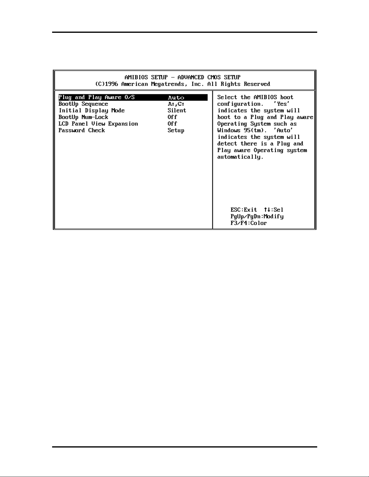
Figure 1-19 shows an example advanced CMOS setup window.
Figure 1-19 The Advanced CMOS Setup Menu
Page 32

Technical Information 1-23
y
y
y
g
g
Table 1-7 Advanced CMOS Setup Menu
Item Function
Plug and Play Aware
O/S
Bootup Sequence Allows you to configure the notebook to which drive it will first
Initial Display Mode
Bootup Num-Lock
LCD Panel View
Expansion
Password Check
Selects the AMIBIOS boot configuration.
stem boots to a Plug and Play aware operating system,
s
such as Windows 95.
automaticall
operating system. The default for this setting is
to look for the operating system. The available options are
tr
“C:, A:”
“C:, A:”
and then look at the diskette drive.
“A:, C:”
and then look at the hard drive.
The default for the system is
Selects the start-up logo dislplay. Selecting
the Windows 95 Logo while selecting
NEC Logo. The default is
Specifies whether NumLock is
startup. The default is
Selects the panel view mode.
some video modes.
adversely affect the graphic/text quality. The default is
Specifies a password check level. Selecting
a password for entering this utility. Selecting
quires a password for enterin
and resuming from Suspend. When
Ctrl+Alt+Backspace
ing
password is entered. The Caps Lock and Scroll Lock LED’s
flash in sequence, while waitin
word.
detects that there is a Plug and Play aware
“A:, C:.”
or
means that the system first looks at the hard drive
means that the system first looks at the diskette drive
“Auto”
“Off.”
“On”
indicates the system
“A:, C:.”
“Silent.”
“On”
“Off”
expands the panel view, but it may
this utility, booting the system,
locks up the keyboard until the
for the user to enter a pass-
“Yes”
indicates the
“No.”
“BIOS”
“Silent”
“Off”
or
reduces the panel view in
“Setup”
“Always”
displays
displays the
at system
requires
“Always”
is set, press-
“Off.”
re-
Page 33
1-24 Technical Information
g
y
g
g
y
g
y
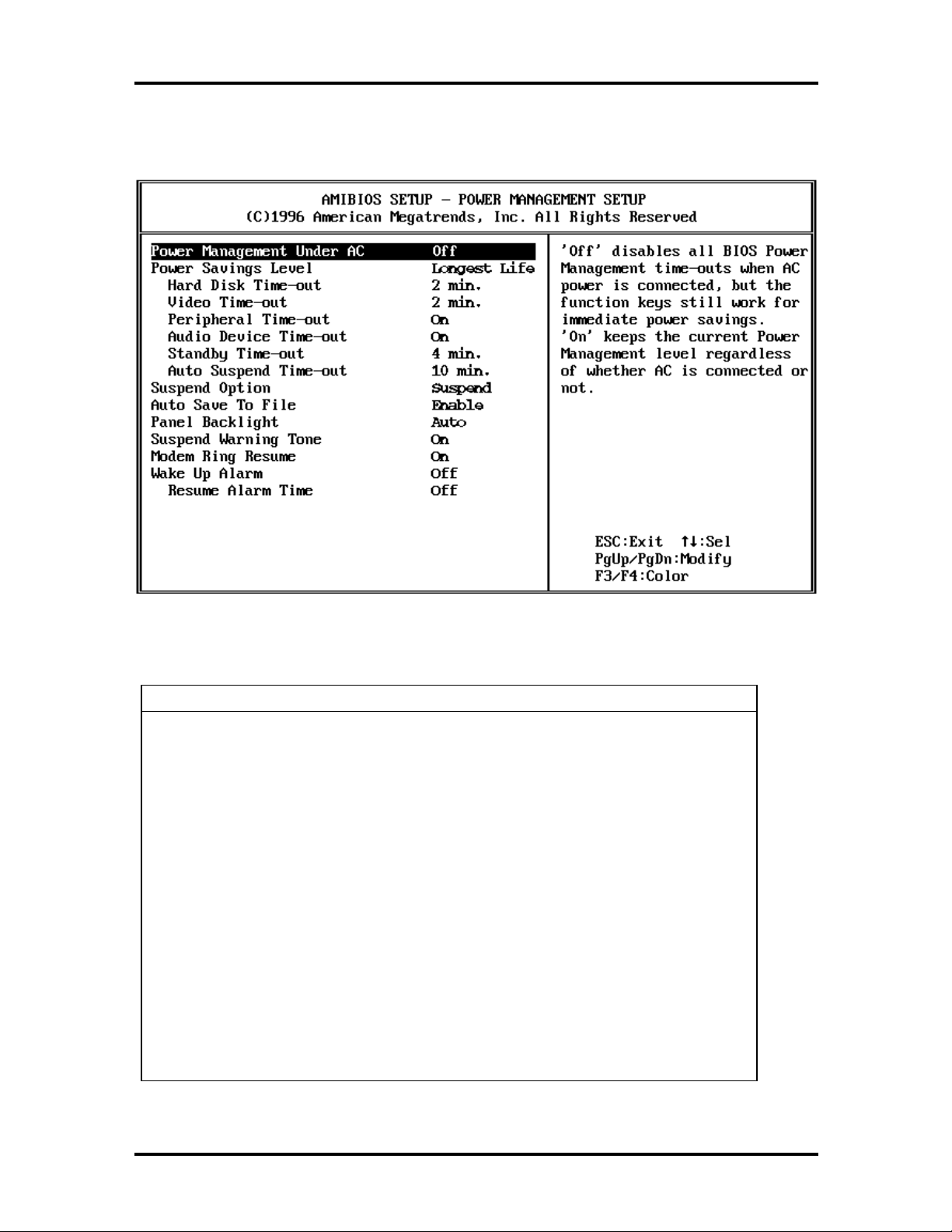
Figure 1-20 shows an example power management setup window.
Figure 1-20 The Power Management Setup Menu
Table 1-8 Power Management Setup Menu
Item Function
Power Mana
Under AC
Power Savings Level
ement
Selecting
outs when AC power is connected, but the function ke
work for immediate power savin
Selecting
ardless of whether AC is connected or not.
re
Default for this option is
This option allows
mode.
“OFF”
allows
“High Perform”
“Longest life”
“Off”
disables all BIOS Power Management time-
s still
s.
“On”
keeps the current power management level
“Off.”
ou to select the proper power savin
disables all BIOS Power Management time-outs and
ou to set your own customized settings.
provides improved system performance
provides the best battery life.
The default for this option is
“Longest Life.”
Page 34

g
y
y
g
y
Table 1-8 Power Management Setup Menu (cont’d)
Item Function
Suspend Option Selecting
Power Mana
Suspend/Resume button. Selecting
saves the s
notebook.
resume, press the Power button. The default for this option is
“Suspend.”
Technical Information 1-25
“Suspend”
ement mode. To resume, press the
stem state to the system disk and powers off the
“STF”
allows a fast resume time and is a
“STF”
(Save to File)
mode is a Power Management mode. To
Auto Save To File If this feature is
Save To File (STF) mode after thirt
the Suspend mode.
Panel Backlight Selects the LCD screen backlight intensity.
“Auto”
“Standard”
inactivity.
“Full”
“Standard”
The default for this option is
Suspend Warnin
Tone
Modem Ring Resume Chooses whether the system automatically resumes when the
Wake Up Alarm Lets you set a resume time from Suspend mode. The default
Specifies whether the s
pend mode starts. Select
tone. Default for this option is
modem receives a transmission. The default for this option is
“On.”
for this option is
a
automatically switches the backlight from
gives the highest level of backlight intensity.
“Resume Alarm Time.”
“Enabled,”
after 15 seconds of keyboard and PS/2 mouse
helps save battery life.
“Off”
the system automatically enters
(30) minutes of being in
“Full’
“Full.”
stem warning tone sounds when Sus-
“On”
to enable Suspend warning
“On.”
. If you select
‘On’
you must designate
to
Page 35
1-26 Technical Information
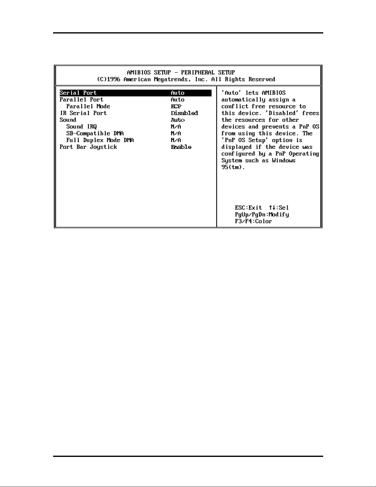
Figure 1-21 shows an example peripheral setup menu window.
Figure 1-21 The Peripheral Setup Menu
Page 36

Technical Information 1-27
g sy
g
g
g
y
g
g
g
g
Table 1-9 Peripheral Setup Menu
Item Function
Serial Port
Parallel Port
Parallel Mode ECP provides the best performance and is recommended.
IR Serial Port
Sound
PortBar Joystick
Selecting
conflict free resource to this device. Selecting
frees the resources for other devices and prevents a PnP
operating system from using this device. The
Setup”
operatin
option is
Selecting
flict free resource to this device. Selecting
the resources for other devices and prevents a PnP operatin
systems from using this device. The
appears if the device was confi
system, such as Windows 95. The default for this option is
“Auto.”
Certain devices ma
lel mode. Please refer to that device’s documentation. The
default for this option is
Selecting
flict free resource to this device. Selecting
the resources for other devices and prevents a PnP operatin
system from using this device. The
appears if the device was confi
system, such as Windows 95. The default for this option is
“Disabled.”
Selecting
flict free resource to this device. Selecting
the resources for other devices and prevents a PnP OS from
using this device. The
device was confi
Windows 95. The default for this option is
This option allows you to
joystick.
“Auto”
option appears if the device was configured by a PnP
“Auto.”
“Auto”
“Auto”
“Auto”
lets AMIBIOS automatically assign a
“Disabled”
“PnP OS
stem, such as Windows 95. The default for this
lets AMIBIOS automatically assign a con-
“Disabled”
“PnP OS Setup”
ured by a PnP operatin
only work properly with a specific Paral-
“ECP.”
lets AMIBIOS automatically assign a con-
“Disabled”
“PnP OS Setup”
ured by a PnP operatin
lets AMIBIOS automatically assign a con-
“Disabled”
“PnP OS Setup”
ured by a PnP operating system, such as
“Enable”
option appears if the
“Auto.”
“Disable”
or
frees
option
frees
option
frees
the PortBar
Page 37

1-28 Technical Information
SYSTEM UPGRADES
The NEC Versa notebook is easily upgradable to a higher capacity hard drive. In addition,
you can add an optional second memory module to increase the system memory up to
128 MB. This section provides the settings needed as well as illustrations for upgrading the
system.
For NEC Versa 2700 Series notebooks, the following memory configurations are
applicable:
Table 1-10 16-MB Memory Configurations
Upper Socket Lower Socket Total Memory
16 MB empty 16 MB
16 MB 16 MB 32 MB
16 MB 32 MB 48 MB
16 MB 64 MB 80 MB
Table 1-11 32-MB Memory Configurations
Upper Socket Lower Socket Total Memory
32 MB empty 32 MB
32 MB 16 MB 48 MB
32 MB 32 MB 64 MB
32 MB 64 MB 96 MB
Table 1-12 64-MB Memory Configurations
Upper Socket Lower Socket Total Memory
64 MB empty 64 MB
64 MB 16 MB 80 MB
64 MB 32 MB 96 MB
64 MB 64 MB 128 MB
Page 38

Section 2
General Specifications
The following table lists NEC Versa 2700 Series system specifications.
Table 2-1 NEC Versa 2700 Series Specifications
Item Specification
CPU Pentium P55C-133/150/166/P55CLM-200/233 MHz
with MMX TCP Package
On-Board Memory 16 MB
SO-DIMM Module
Slot
System Management
Power Management Operational Modes:
Hard Disk Drive Removable HDD Module
CD-ROM Reader Built-in CD-ROM Reader 13.7mm High
Two Slots
16 MB in first slot
Upgradeable to 128 MB
256 KB L2 Cache
2M (256K x 8) Flash BIOS:
Includes System and VGA
Shadow BIOS Capability
Full On Mode
Standby Mode
Suspend to DRAM (STR)
Suspend to File (STF)
Peripheral Automatic Power Down
Cover Switch Support
Suspend/Resume Button
2.5-inch format/12.7mm high
Enhanced IDE Interface
Support IDE PIO mode up to MODE 4
Support IDE MASTER MODE
1.4 GB/Higher Capacity Upgrade
16X speed (maximum, variable speed support
Versa 2730M, Versa 2730MT, Versa 2750MT, Versa 2760MT)
20X speed (maximum, variable speed support
Versa 2770MT, Versa 2780MT)
Both readers have an IDE Interface
Diskette Drive Non-Removable Diskette Drive
720 KB/1.2 MB/1.44 MB Mode Support (3 mode)
Page 39

2-2 General Specifications
y
y
y
y
y
y
y
y
g
g
g
y
Table 2-1 NEC Versa 2700 Series Specifications (cont’d)
Item Specification
Display 12.1” TFT Color LCD Module or 12.1” DSTN Color LCD Module:
800 x 600 in 64K colors
External CRT Capabilit
640 x 480 in 16M colors
800 x 600 in 16M colors
1024 x 768 in 64K colors
LCD/CRT Displa
32-bit PCI Bus
LCD/CRT Auto-Sense
Video RAM 2 MB embedded in VGA Controller
PCMCIA Slots Two Type II slots or one Type III slot
PCMCIA Socket compatible with CARD BUS standard
ZV Support
Pointing Device ALPS Glide Pad
PS/2 Interface
:
Simultaneousl
Keyboard Keyboard Layout:
US La
European La
Support Extra Windows 95 Hot Ke
Inverted T Compatible Direction Ke
Overlapped/Embedded Function and Numeric Keypad
Internal and External Keyboard Simultaneous Function
Hot Ke
Operation
I/O Port 25-pin Parallel Port (W / EPP, ECP) (LPT1)
Fn + F2 = Text Hi
Fn + F3 = LCD > CRT > LCD/CRT Simul.
Fn + F5 = LCD Backli
Fn + F6 = PC Speaker L/M/H/Mute
Fn + F7 = PMU Level
Fn + F12 = Scroll Lock
Fn + Left Ctrl = Simulate the ri
Fn + Suspend = Save-to-Disk on Demand
Power Switch + Suspend = Force Power Off
9-pin Serial Port (W / FIFO) (COM1)
15-pin VGA Monitor Port
NEC Y-Cable Support (Keyboard & Mouse)
DC-IN Jack
out - 87 Keys
out - 88 Keys
s
hlight
ht On/Off
ht Ctrl ke
FIR Port (COM2 Port)
PortBar Expansion Port
USB Port - 1
Page 40

General Specifications 2-3
y
g
y
g
Table 2-1 NEC Versa 2700 Series Specifications (cont’d)
Item Specification
PortBar Supports:
Game port
External Ke
External PS/2 Mouse
Serial Port (COM1)
Printer Port (LPT1)
DC-In Jack
USB Ports (2)
Kensington Lock
Audio Supports external Stereo Headphone Jack
Supports external Stereo Line-In Jack
Supports external microphone Jack
Built-in Stereo speakers and Woofer
Built-in microphone
Status Indicators LED Displays
Power Status LED
Char
Suspend LED
HDD LED
FDD LED
Num Lock - Enable
Caps Lock - Enable
Scroll Lock - Enable
board
e LED
Power Supply
Heat Dissipation Heat Pipe + Fan
Dimension 12.0 in. (306mm) (L) x 9.6 in. (241mm) (W) x 1.9 in. 49mm (H)
Optional Items Port Replicator (PortBar)
Adapter
AC
AC 100V to 240V, 47/63Hz, 45W (Max)
Dimensions: 4.1 in. (106mm) (L) x 2.3 in. (60mm) (W) x
1 in. (25.4mm) (H)
Batter
8 cells lon
(Total - 31.68W)
8 cells 18650-size 2600mA/hr Li-Ion Battery, 14.4V
(Total - 37.44W)
Input
A-size 3300mA/hr Ni-MH Battery, 9.6V
Page 41

2-4 General Specifications
g
g
g
g
y
y
y
g
g
y
g
Table 2-1 NEC Versa 2700 Series Specifications (cont’d)
Item Specification
Key Components CPU: MMX 133 MHz, TCP Package (Intel)
MMX 150 MHz, TCP Packa
MMX 166 MHz, TCP Packa
MMX 200 MHz, TCP Packa
MMX 233 MHz, TCP Packa
LCD: 12.1” Color TFT SVGA - (NEC, NL8060BC31 - 02)
12.1” Color DSTN SVGA - (Panasonic, EDMGR68KDF)
CD-ROM: CD-316E (13.7mm) - (TEAC)
CD-220E (13.7mm) - (TEAC)
Hard Disk Drive: 1.4 GB MK1401MAV (12.7MM) - (Toshiba)
2.1 GB DK225A 21 (12.7mm) - (Hitachi)
Diskette Drive: FD1238T - (NEC)
board: KFREBA004A ALPS
Ke
e (Intel)
e (Intel)
e (Intel)
e (Intel)
Glide Pad: KGDDDH Alps
Batter
2600mA/hr / 14.4V Li-Ion - (San
Core Lo
Super I / O: (NS, PC87338VJG)
VGA Chip: (Neo Ma
Ke
PCMCIA Controller: (TI, PCI1131)
FIR Chip: (HP, HSDL1100-07)
Audio Chip: (Yamaha, 715B)
Audio Amplifier: (TI, TPA0102)
Clock Generator: (IMI, IMICS671)
Micro Controller: (Micro Chip, PIC16C62A + PMU-03)
Flash ROM: (ATMEL, AT29C020)
RS232 Driver: (Maxium, MAX3243)
: 3300mA/hr / 9.6V NiMH - (Sanyo)
o)
ic: (Intel, MT2)
ic, NM2160)
board Controller: (Mitsubishi, M38813M4)
ulator: (NS, LP2952)
Re
PCMCIA Power Switch: (TI, TPS2206)
MOSFET: (NS, 9410)
MOSFET: (NS, 9947)
Page 42

SYSTEM BOARD SPECIFICATIONS
y
y
y
y
y
g
y
The following table lists system board specifications.
Table 2-2 System Board Specifications
Item Specification
Cr
Clock
stal 8 MHz SMD Type x 1
stal 14.318 MHz SMD Type x 1
Cr
stal 32.768 MHz SMD Type x 1
Cr
stal 4 MHz SMD Type x 1
Cr
stal 4.19 MHz SMD Type x 1
Cr
Clock Generator (ICWORKS 48569-02, 48 pin)
Buffer included in Clock Generator
General Specifications 2-5
ROM
System Chipset 430 TX (Intel)
Super I/O
Keyboard Controller
Micro Controller
RTC Battery
Audio
Amplifier (TI TPA0102)
DRAM 144-pin 2 Slot DIMM x 2
VGA 2 MB Video DRAM (NeoMagic 2160)
PCMCIA (TI 1131)
L2 Cache 32 K x 32 SRAM TQFP (3.3V/6ns) x 2
Flash ROM for BIOS
256 K x 8, 120 ns
32-pin PLCC Package
320-pin BGA (MTXC)
320-pin BGA (P11X4)
100-pin TQFP (NS87338)
64-pin QFP (Mitsubishi 38813-M4)
28-pin SOIC (PIC16C62A)
60mA, 3.0V NiMH Battery (VARTA)
100-pin TQFP (Yamaha YMF715B-S)
(TI TPS2206)
TAG RAM SOP 32 K x 8
NEC Micro Controller 80 PIN
e Controller
Char
Batter
(NEC D75517G-416)
HP IR Module 4 MB Transfer
Gas Gauge Controller
Page 43

2-6 General Specifications
y
y
y
g
g
Table 2-2 System Board Specifications (cont'd)
Item Specification
Internal Connectors To LCD Panel: CN52, 40 pin (HRS)
To LED Board: CN51, 10 pin (Molex)
To LCD- LED Board: CN53, 11 pin (Molex)
To HDD: CN60, 50 pin (Molex)
To CD-ROM: CN57, 50 pin (Molex)
To RTC Batter
To I/O Board: CN70, 120 pin (AMP)
To LCD Panel: CN52, 40 pin (HRS)
To LED Board: CN51, 10 pin (Molex)
To LCD- LED Board: CN53, 11 pin (Molex)
To HDD: CN60, 50 pin (Molex)
To CD-ROM: CN57, 50 pin (Molex)
To RTC Batter
To I/O Board: CN70, 120 pin (AMP)
To PCMCIA Socket: CN71, 156 pin (HRS)
To FAX/MODEM Board: CN66, 80 pin (Molex)
To CPU Board: CN54, 240 pin (HRS)
To Glide Pad: CN55, 6 pin (ELCO)
To Internal Ke
To Woofer: CN64, 2 pin (Molex)
To Internal Microphone: CN62, 2 pin (Molex)
To Internal Speaker: CN59, 4 pin (Molex)
To MODEM Jack: CN58, 2 pin (Molex)
To FDD: CN63, 26 pin (ELCO)
: CN65, 2 pin (Molex)
: CN65, 2 pin (Molex)
board: CN56, 21 pin (ELCO)
External Connector To CRT: CN68, 15 pin (Suyin)
To USB: CN72, 4 pin (Ber
To PortBar: CN69, 80 pin ((Ber
To Headphone Jack: CN78, 5 pin (Hosiden)
To Line-In Jack: CN75, 5 pin (Hosiden)
To External Microphone Jack: CN77, 5 pin (Hosiden)
To Fax/Modem Jack: CN73, 6 pin (Molex)
)
)
Page 44

DC CONVERTER BOARD SPECIFICATIONS
g
g
g
y
y
The following table lists the DC converter board specifications.
Table 2-3 DC Converter Board Specifications
Item Specification
Structure PUD76: DC/DC Buck Converter 5V/3.3V
FM-04: DC/DC Boost Converter
CC04: Constant Current Circuit
LTC1435: DC/DC Buck Converter Vcore & Vio
MAX3243: Transceivers RS-232
Signal Standard Main Battery: NiMH/Li-Ion
AC Adapter: ADP52
Bridge Battery: 6 Cell NiMH
General Specifications 2-7
Characteristics
PUD76: DC/DC Converter
Input Rated Volta
Li-Ion DC 14.4V
Adapter ADP52 DC 19V
Output Rated Current:
3VDDS 5VDDS
PEAK 3.7A 4.5A
MAX 3.5A 3.2A
TYP 1.75A 1.3A
MIN 0.3A 0.5A
MAX 100mA 100mA
TYP 6mA 6mA → Suspend
MIN 1mA 1mA
e 3.3V 5.0V
Volta
ulation -2.5%+4.0% -2.5%+4.0%
Re
Ripple 80mV 80mV
Ripple Noise 150mV 150mV
Protection Circuit Short Circuit → Reset b
Over Current → Reset b
Input - Output Interface:
CN1 1. DC-In 2. DC-In
DC-In 4. 5VON1
NC 6. FULPDN0 (Suspend)
GND 8. GND
GND 10. GND
CN2 1. 5VDDS 2. 5VDDS
VAR5 4. GND
5. GND 6. GND
GND 8. VAR3
9. 3VDDS 10. 3VDDS
e: Battery NiMH DC 9.6V
→
→
pwr on
pwr on
Page 45

2-8 General Specifications
g
g
y
g
g
y
g
g
g
Table 2-3 DC Converter Board Specifications (cont'd)
Item Specification
FM-04: DC/DC Converter (PC Cards)
Input Rated Volta
Output Rated Volta
Ripple: 200mVp-p
Noise: 360mVp-p
Protection: Short Circuit → Reset b
Input - Output Interface:
CN1 1. GND 2. GND
Output 4. Output capacitor terminal
5. Input 6. On/Off
CC04: Constant Current Converter for Charge
Input Rated Volta
e Voltage: 7.0V ~ 20.0V
Char
stem Current: 0.0A ~ 2.4A
S
e Current: 0.0A ~ 1.7A
Char
Ripple: 350mVp-p
Noise: 500mVp-p
Input - Output Interface:
N.C 2. ADP In
3. N.C 4. GND
5. GND 6. CHG Out
7. N.C 8. ADP Out
LTC1435 : DC/DC Converter
Input Rated Volta
Li-Ion DC 14.4V
Adapter ADP52 DC 19V
Output Rated Current:
Vio Vcore
PEAK 400mA 4.0A
MAX 300mA 3.2A
TYP 100mA 2.0A
MIN 10mA 100mA
ulation ±5% ±5%
Re
Ripple 80mV 80mV
Ripple Noise 150mV 150mV
e: DC 5V±10%
e : 12V ± 5%
pwr on
e: AC Adapter DC 18.5V ~ 20.0V
e : Battery NiMH DC 9.6V
MAX3243 : Transceiver
RS-232 Serial Port
Sub-Battery NiMH : VARTA 6 Cell
Page 46
LED INDICATOR BOARD SPECIFICATIONS
The NEC Versa 2700 uses the following LEDs.
HDD LED x 1
FDD LED x 1
Num Lock LED x 1
Cap Lock LED x 1
Scroll Lock LED x 1
Power Switch x 1
Suspend Button x 1
The following table lists LED indicator board specifications.
General Specifications 2-9
Table 2-4 LED Indicator Board Specifications
Item Specification
External Connector To Mother Board : CN101, 10 pin (Molex)
To Cover Switch : CN102, 2 pin (Molex)
I/O BOARD SPECIFICATIONS
The following table lists I/O board specifications.
Table 2-5 I/O Board Specifications
Item Specification
CPU Core Voltage: 16 pin, SOP (LTC1435)
+5V Voltage: NEC Module Board
+3V Voltage: NEC Module Board
+12V Voltage: NEC Module Board
Internal Connector To Mother Board: CN6, 100 pin (AMP)
External Connector To COM Port: CN1, 9 pin (Suyin)
To LTP Port: CN3, 25 pin (Suyin)
To Keyboard Connector: CN4, 6 Pin (Eoxcon)
To Adapter: CN5, 3 pin (HRS)
To Battery pack: CN7, 8 pin (AMP)
Page 47

2-10 General Specifications
g
g
y
g
g
LCD INVERTER BOARD SPECIFICATIONS
The following table lists the LCD inverter board specifications.
Table 2-6 LCD Inverter Board Specifications
Item Specification
Ratings Input Voltage: 8V to 20V DC
Tube Current: 2 to 5 mA rms
VBL-adj: 0 to 4.7V DC
Working Frequency: 50 to 58 KHz
Detection No-load OVP clamp: No Connection to LCD
Constant Current Output: Output Short
Connector CN1 6 pin Molex (53261-0610)
1. V+ (8.0V to 20.0V)
Environment
Specification
2. V+ (8.0V to 20.0V)
3. On/Off (H - On, L - Off)
4. VBL - adj (0.0V to 4.7V)
5. GND
6. GND
CN2 2-pin JST SM02(8.0)H-BHS
1. HV (Hi
2. Return
Temperature
Operation : 0° to 45° C
Stora
Humidit
Operation : 20%RH to 80%RH
Stora
Altitude
Operation : 10,000 ft
Stora
e : -20° to 60° C
e : 10%RH to 90%RH
e : 15,000 ft
h Voltage)
Burn-In
Loading : LCD Module or Dummy Load
Input : 19V (Max/Adapter In)
Page 48
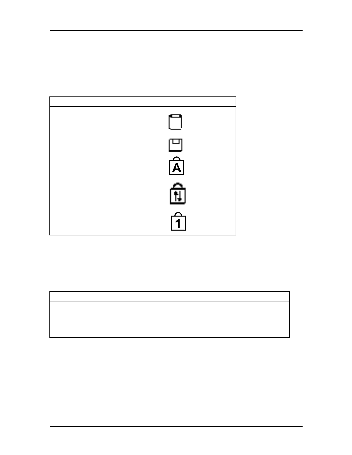
General Specifications 2-11
LED STATUS INDICATORS
The following table lists NEC Versa 2700 Series LEDs. For example, the Hard Drive Access LED lights to indicate the hard drive is in use and being accessed.
Table 2-7 Status LED Descriptions
Item LED
Hard Drive Access
Diskette Drive Access
Caps Lock
Scroll Lock
Num Lock
DISKETTE DRIVE SPECIFICATIONS
The following table lists the standard diskette drive specifications.
Table 2-8 Diskette Drive Specifications
Item Specification
Module 3.5” Module
Mode 3 Mode FDD (1.44 MB/ 720 KB)
Unit Size 4.29 in. (L) x 3.74 in. (W) x 0.50 in (H) (110mm x 96mm x 12.7mm )
Page 49

2-12 General Specifications
HDD UNIT SPECIFICATIONS
The following table lists the standard hard drive specifications.
Table 2-9 Hard Disk Drive Specifications
Item Specification
Module 2.5” Removable HDD Module
Capacity 1.4 GB or 2.1 GB
Interface Enhanced IDE Interface
Unit Size 3.90 in. (L) x 2.73 in. (W) x 0.50 in. (H)
(100mm x 70mm x 12.7mm )
CD-ROM SPECIFICATIONS
The following table lists the standard CD-ROM reader specifications.
Table 2-10 CD-ROM Reader Specifications
Item Specification
16X
Model Number
(TEAC)
Mode IDE Interface IDE Interface
Data Transfer
(Sustained)
Data Transfer (Burst) 16.7 MB/sec 16.7 MB/sec
Unit Size 5.48 in. (L) x 5.09 in. (W) x
CD-316E CD-220E
2,400 KB/sec (Max) 3,000 KB/sec (Max)
0.53 in. (H) (140.5mm x
130.5mm x 13.7mm )
Specification
20X
5.07 in (L) x 4.99 (W) x
0.50 (H) (130mm x 128mm x
12.7mm)
NIMH BATTERY PACK SPECIFICATIONS
The following table lists the standard battery specifications.
Table 2-11 Battery Specifications
Item Specification
NiMH
Specification
Li-Ion
Capacity 3300 mA x 8 cells 2600 mA x 8 cells
Cell Type Long A 18650
Voltage 9.6V 14.4V
Connector 10-Pin 10-pin
Page 50

General Specifications 2-13
DC/DC CONVERTER AND BATTERY CHARGER SPECIFICATIONS
The following table lists DC/DC converter and battery charger specifications.
Table 2-12 DC/DC Converter and Battery Charger Specifications
Item Specification
Input Voltage 6V -> 19V
Output Voltage 5V, 3.3V
Output Current 0.1A, 2.5A
Output Ripple
Voltage
Protection Short Circuit, Over Current
Efficiency 80% Min. (Typ.)
PCB 1.2mm/6 Layers
150mV, 100mV
BATTERY CHARGER SPECIFICATIONS
The following table lists battery charger specifications.
Table 2-13 Battery Charger Specifications
Item Specification
Input Voltage 20V (Max.)
Support Battery NiMH Battery (12V) or Li-Ion Battery (12V)
Protection Max. Temp., Max. Timer
Charge Method
Max. Temperature
Delta T/Delta t: 1
o
53
C ~ 60oC
o
C (min.)
Timer Setting 360 Min.
Charge Time Machine On: 4 hours
Machine Off: 2 hours
Charge IC BQ2005
Connector To M/B:
10 Pin & 18 Pin, Male, Straight, DIP/SMT
Page 51

2-14 General Specifications
KEYBOARD SPECIFICATIONS
The following table lists keyboard specifications.
Table 2-14 Keyboard Specifications
Item Specification
Key Switch Type Membrane
Key Stroke
Operating Force
Key Pitch 19.05mm
3.0 ± 0.5mm
50 ± 20GF
AC/DC ADAPTER SPECIFICATIONS
The following table lists AC/DC adapter specifications.
Table 2-15 AC/DC Adapter Specifications
Item Specification
Input Voltage AC 90V -> 265V, 50 -> 63Hz
Ripple Noise 100mvp-P
Output Voltage 20V Max.
Protection Short Circuit UVP, OVP
AC Cord Safety Approval, FCC Shielding AC cord
DC Output Cable 2-pin, 100cm long with coil at system end
Indicator AC Power On
Unit Size 4.68 in. (L) x 2.42 in. (W) x 1.40 in. (H)
120mm x 62mm x 36mm
Page 52
LCD/LED BOARD SPECIFICATIONS
The NEC Versa 2700 features the following LCD/LED items.
Charge LED x 2
Power LED x 2
Suspend LED x 2
Contrast VR x 1
Brightness VR x 1
The following table lists LCD/LED Board specifications.
Table 2-16 LCD/LED Board Specifications
Item Specification
General Specifications 2-15
External Connector To Mother Board: CN2, 11 pin (Molex)
To Inverter: CN1, 6 pin (Molex)
Page 53

2-16 General Specifications
g
y
BIOS SPECIFICATIONS
The following table lists BIOS specifications.
Table 2-17 BIOS Specifications
Item Specification
BIOS Feature
CPU Auto detects the CPU type and speed
DRAM Auto sizing and detection
Cache
Hard Disk
Multi Boot Allows user to select boot from FDD, HDD, or CD-ROM
Plug and Play Supports PnP Run Time Service and conflict-free allocation of resource
• Boot Block/Crisis Rescue
•
APM 1.2 Compliance
•
Support PCI 2.1 Specifications
•
Supports Win95, WFWG, WinNT, Win3.11, and DOS 6.2x
•
Level 2 Sync/Async SRAM auto sizing and detection
•
Supports Pannin
supported.
•
Enhanced IDE Specifications
•
Supports auto detection
•
Supports LBA mode for larger capacity HDD
•
Supports 32-bit PIO transfer
•
Supports Multi-sector transfer
•
Supports ultra DMA
•
Supports Fast PIO mode 1 - 4 transfer
during POST
while LCD display resolution is greater than
Intelligent Battery Supports BIOS interface to pass battery information from the PMU
Controller (PMU-03 & PIC16C62) to the application
Keyboard Controller
PCMCIA Compliant with PCMCIA 2.1 Specification
CD-ROM Supports boot from CD-ROM
PortBar I/O port replicator duplicates the following ports:
Supports Fn hot keys, two Win95 hot keys, built-in Glide Pad and external
PS/2 mouse/keyboard
CRT Port
Printer Prot
COM1 Port
MIDI/Game Port
PS/2 Mouse & Standard Ke
DC-In Jack
board Port
Page 54

Table 2-17 BIOS Specifications (cont'd)
g
y
y
y
y
g
y
y
g
y
y
y
g
y
y
Item Specification
General Specifications 2-17
Power Management
Support
The power management is compliant with APM 1.2 specifications and
supports the followin
On Mode
Doze Mode — Transparent to the user
Standb
Suspend to RAM (STR) Mode
Suspend To Disk (STD) Mode
Soft-Off Mode (Soff)
Mechanical Off Mode (Moff) — Transparent to BIOS
Mode — Also known as the Power On Suspend Mode
power states:
POWER MANAGEMENT FEATURES (MODE DEFINITION)
The following table lists power management specifications.
Table 2-18 Power Management Modes
Mode Mode Definition
Full-On The system state where no devices are power managed and the
system can respond to applications with maximum performance.
Doze The CPU clock is slowed down and all other devices are full-on.
Standby
(POS)
A suspend state where all system board components are still
powered-on except for the s
and CPU buses are driven to the inactive idle state. The s
memor
raphics frame buffer is powered and refreshed by the graphic chip.
The s
mode to support refresh of these memor
enabled “resume event” can brin
suspend (POS) state. The PIIX4 also provides a resume timer that
allows the system to resume after a programmed time has elapsed.
is powered and refreshed by the memory bridge, and the
stem provides a 32 KHz clock (SUSCLK) in this Suspend
stem clock generator device. The PCI
subsystems. Only an
the system out of the powered-on
stem
Suspend To RAM
(STR)
Suspend to Disk
(STD)
A suspend state where all system board components are powered
off. The CPU/2 and PCI busses are powered off. All devices
connected to the CPU/L2 and PCI buses must either be powered-off
or isolate their bus interfaces. The s
refreshed b
clock (SUSCLK) in this suspend mode to support refresh of these
memor
the platform out of the suspend to RAM (STR) state.
A suspend state where the context of the entire system is saved to
disk, all s
are stopped. An
RTC, can bring the platform out of the suspend to disk (STD) state.
the graphics chip. The system provides a 32 KHz
subsystems. Only an enabled “resume event” can brin
stem board components are powered-off, and all clocks
enabled “resume event”, such as PowerBTN or
stem memory is powered and
Page 55

2-18 General Specifications
y
g
g
Table 2-18 Power Management Modes (cont'd)
Mode Mode Definition
Soft Off:
(SOFF)
Mechanical Off
(MOFF)
This is the same as suspend to disk except the context of memor
is not saved. The system resumes from a Soft Off as if a hard reset
had occurred.
All power except the RTC was removed from the system. (This
mode is transparent to BIOS.)
Table 2-19 Power Status of Local Devices
Component Full-On Doze POS STR STD/Soff
CPU On Stop
Grant
DRAM On On Slow Refresh Slow Refresh Power Off
HDD On On Low Power Power Off Power Off
FDD On On On Power Off Power Off
M#8813 (KBC) On On On Low Power Power Off
PIC16C62 (µP)
VGA / VRAM On On Low Power Low Power Power Off
TI 1131 (PCMCIA) On On Low Power Low Power Power Off
On On On Low Power Low Power
Stop Clock Power Off Power Off
Sound On On Low Power Power Off Power Off
LCD Panel
Backlight
IR Module On On Low Power Power Off Power Off
Super I/O Chip On On Low Power Power Off Power Off
Wake-up Events — IRQ0~15 IRQ1~15
On On Power Off Power Off Power Off
Ring In
Suspend Button
Indicator
Rin
RTC Alarm
Power Button
Indicator
Rin
RTC Alarm
Page 56

General Specifications 2-19
POWER MANAGEMENT FEATURES (MODE TRANSITION)
The following table lists power management transition modes.
Table 2-20 Mode Definitions
Power State/
Control Pin
Full-On 1 1 1 1 1 1
Doze 1 1 1 1 1 1
Standby 0 0 0 1 1 1
STR 0 0 0 0 1 1
STD/SOFF 0 0 0 0 0 0
Mechanical Off 0 0 0 0 0 0
SUB_STAT1# SUB_STAT2# SUSA#
SUSB#
SUSC#
HOT KEY DEFINITION
The following table lists hot key definitions.
Table 2-21 Hot Keys
Function Key Content
Fn + F2 Toggle text highlight (in DOS)
PWRON
Fn + F3 Toggle Display (CRT/LCD/Simul)
Fn + F4 Enter Standby Mode
Fn + F5 LCD Panel Backlight Standard/Full
Fn + F6 System Speaker On/Off
Fn + F7 P/M Level (Toggle between Highest Performance, Longest
Battery, Custom, and Off Power Management Level)
Fn + F12 Scroll Lock
Fn + LeftCtrl Simulate right Ctrl Key
Fn + Z Windows key for Windows 95
Fn + X Application key for Windows 95
Page 57

2-20 General Specifications
HOT KEYS SUPPORTED BY EXTERNAL KEYBOARD DEFINITION
The following table lists external hot key definitions.
Table 2-22 External Hot Keys
Function Key Content
Fn + F2 Toggle Text Highlight (in DOS)
Fn + F3 Toggle Display (CRT/LCD/Simul)
Fn + F4 Enter Standby Mode
Fn + F5 LCD Panel Backlight Standard/Full
Fn + F6 System Speaker On/Off
Fn + F7 P/M Level (Toggle between Highest Performance, Longest
Battery, Custom, and Off Power Management Level)
Fn + Suspend Save-to-Disk on Demand
Power Switch + Suspend Force Power Off
ENVIRONMENTAL SPECIFICATIONS
The following table lists appropriate operating temperatures.
Table 2-23 Environmental Specifications
Item Specification
Operating Mode
Non-Operating
o
5
C ~ 35oC (80%)
o
-20
C ~ 60oC (90%)
POWER SOURCE SPECIFICATIONS
The following table lists system power specifications.
Table 2-24 Power Specifications
Input Nominal Version
AC Voltage 100 ~ 250 V 90 ~ 265 V
AC Frequency 50 / 60 Hz 47 ~ 63 Hz
Page 58

VIBRATION SPECIFICATIONS
The following table lists vibration specifications.
Table 2-25 Vibration Specifications
Item Specification
Operating Mode Direction of Movement: X, Y, Z Axis
Vibration Level: 5 ~ 500 ~ 5 Hz, 0.5 Gs Acceleration
Duration Time: 60 min. for each axis
Non-Operating Direction of Movement: X, Y, Z Axis
Vibration Level: 5 ~ 500 ~ 5 Hz 2 Gs Acceleration
Duration Time: 60 min. for each axis
SHOCK SPECIFICATIONS
The following table lists system shock specifications.
General Specifications 2-21
Table 2-26 Shock Specifications
Item Specification
Operating Mode Impact Accelerator: 1g/10g Based on Half Sine-Wave Shock
Pulses of 11 Msec
Number of Shock: 3 Shocks for each of the 6 faces
Direction of movement: 6 Faces
Non-Operating Mode Impact Accelerator: 10g, 20g, 30g, 40g, 50g Based on Half Sine-
Wave Shock Pulses of 11Msec
Number of Shock: 3 Shocks for each of the 6 faces
Direction of Movement: 6 Faces
ELECTRO-STATIC DISCHARGE (ESD) SPECIFICATIONS
The following table lists static discharge specifications.
Table 2-27 Electro-Static Discharge Specifications
Item Specification
Contact Discharge
±2, 4, 8, 12.5, 15 kV
Air Discharge
HCP
VCP
±2, 4, 15 kV
±2, 4 kV
±2, 4 kV
Page 59

Section 3
Hardware Functional Overview
The NEC Versa 2700 Series notebooks consist of several major functions and subsystems
including:
system BIOS – implemented on the system board and Flash ROM
system processor – implemented on the system board
system logic controller – implemented on the I/O board
memory subsystem – implemented on the system board
video subsystem – implemented on the I/O board, LED board, and LCD display
panel
I/O subsystem – implemented on the I/O board
keyboard subsystem – implemented on part of the system board and keyboard
assembly
PCMCIA controller and sockets – implemented on the system board
pointing device subsystem – implemented on the I/O board and keyboard
assemb ly
hard disk subsystem – implemented on the system board and the hard drive
assembly
diskette drive disk subsystem – implemented on the system board and the diskette
drive
CD-ROM subsystem – implemented on the system board and the CD-ROM
reader
power subsystem – implemented on the power supply board, inverter board,
battery packs, and AC adapter.
A simplified block diagram of the notebook is shown on the next page.
Page 60
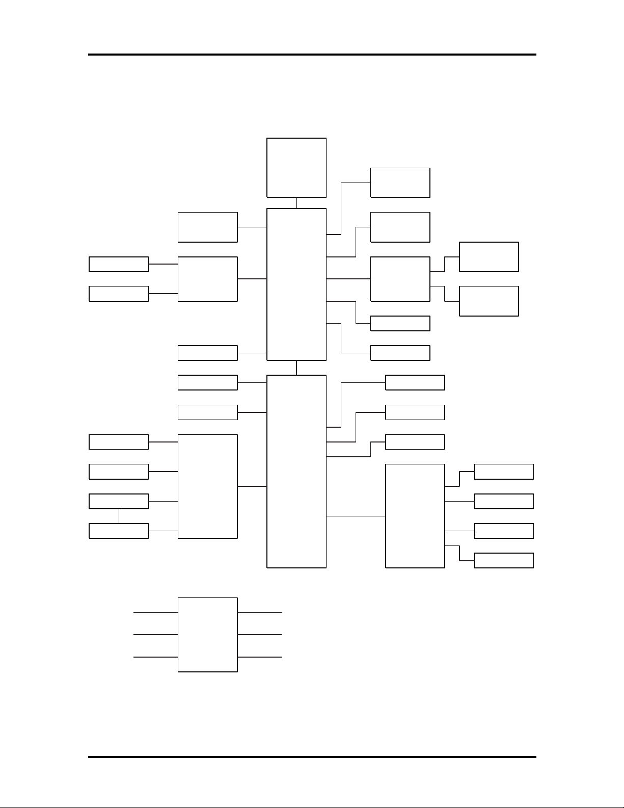
3-2 Hardware Functional Overview
FUNCTIONAL BLOCK DIAGRAM
The following figure shows the NEC Versa 2700 Series functional diagram.
CPU
Pentium MMX
P55C
Tillamook (TCP)
133/150/166/
200/233 MHz
Bank 1
so-DIMM
16/32/64 MB
CRT
LCD
PS/2 Mouse
Glide Pad
Internal Kb
External Kb
L2
Cache
256 KB
VGA
Neo Magic
NM2093
USB
Serial
FDD
Keyboard
Controller
M38813/M4
System PCB
430TX
MTXC
324BGA
Super I/O
NS87338VJG
Bank 2
so-DIMM
16/32/64 MB
PCMCIA
TI
1131
HDD
CD-ROM
Flash ROM
3.3V, 32PLCC
Battery
Printer
Audio PCB
Yamaha
715B
Slot 0
PCMCIA
Slot 1
PCMCIA
Headphones
Microphone
Line-In
Volume Control
Clock
Generator
Figure 3-1 Functional Block Diagram
Page 61

Hardware Functional Overview 3-3
SYSTEM BIOS
The primary function of the system BIOS (Basic Input-Output System) is to provide a series of software interrupts, functions, and sub-functions that control operations on certain
devices, such as the hard disk drive, the diskette drive, and the video subsystem.
The NEC Versa 2700 Series uses the AMIBIOS. The BIOS Setup program is an easy-touse system utility configuration that sets system parameters and copies them on the Flash
ROM chip with the system BIOS.
The Flash ROM chip also includes BIOS Power-On Self Test (POST) diagnostic and booting codes that tests the system components, initializes certain data structures, and boots the
operating system.
System Processor
The system processor function for the notebook is implemented on the system board using
an Intel MMX, P55C-133/150/166/200 or P55CLM-233/266 MHz processor chips. These
processor operate in conjunction with the RAM and ROM memory plus other system con-
e.g
trol logic (
tions).
.
Intel 430TX) to process software instructions (BIOS, Windows, applica-
The P55C microprocessor is a 2.8V desktop/2.5V mobile (the P55CLM is 1.8V) (3.3V I/O)
version of the Pentium processor (75-200). It is functionally similar to the Pentium
processor (75-200) with the following differences: Voltage supplies, maximum bus and core
frequency, and performance. The P55C/P55CLM is socket compatible with the Pentium
processor (75-200) making it possible to design a flexible motherboard that supports both
the Pentium processor (75-200) and the P55C/P55CLM processor. The P55C/P55CLM is
manufactured on an advanced CMOS process, which enables the P55C with a reduced core
voltage supply to run at up to 200 MHz core frequency (the P55CLM can run at up to 266
MHz core frequency.
The P55C/P55CLM, like the Pentium processor (75-200) has built-in arbitration and cache
consistency features for Dual-Processing (DP) which enable a “glueless” dual P55C system
design. The P55C/P55CLM can be configured in both modes, DP or uniprocessing.
The P55C/P55CLM has the complete Pentium processor (75-200) feature set, plus the
following new features:
16 KB 4-way set-associative code cache and 16 KB 4-way data cache, each with
improved fully associative TLBs.
Pool of 4 write buffers used by both pipes.
New Fetch pipeline stage between Prefetch and Instruction Decode with 4-deep
instruction FIFO.
Enhanced branch prediction algorithum.
Page 62

3-4 Hardware Functional Overview
Up to 233 Mhz/266 MHz core frequency operation for both desktop and mobile
systems.
Supports the Intel 430 chipset family. Does not support Intel 82497/82492 or
82498/82493 cache chipsets.
SYSTEM LOGIC CONTROLLER
The System Logic Controller function for the notebook is implemented on the system board
using Intel 430TX PCI Chipset. The 430TX PCIset consists of the TX System Controller
(MTXC) and the PCI ISA IDE Xcelerator (PIIX4). The PCIset forms a Host-to-PCI
bridge and provides the second level cache control and a full function 64-bit data path to
main memory. The MTXC integrates the cache and main memory DRAM control functions
and provides bus control to transfers between the CPU, cache, main memory, and the PCI
Bus.
The second level (L2) cache controller supports a write-back cache policy for cache sizes of
256 Kbytes and 512 Kbytes. Cacheless designs are also supported. The cache memory can
be implemented with pipeline burst SRAMs. An external Tag RAM is used for the address
tag and an internal Tag RAM for the cache line status bits.
For the MTXC DRAM controller, six rows are supported for up to 256 Mbytes of main
memory. The MTXC PCIset is highly integrated by including the Data Path into the same
BGA chip. Using the snoop ahead feature, the MTXC allows PCI masters to achieve full
PCI bandwidth. For increased system performance, the MTXC integrates posted write and
read prefetch buffers. The Intel 430TX PCIset integrates many Power Management features that will enable the system to save power whenever the system resources become idle.
Features Summary:
Supports the Pentium® processor family host bus at 66 MHz at 3.3V and 2.5V.
PCI 2.1 compliant
Integrated data path
Integrated DRAM controller
4 MB to 256 MB main memory
64 Mbit DRAM/SDRAM technology support
FPM (Fast Page Mode), EDO and SDRAM DRAM support
6 RAS lines available
Integrated Programmable-Strength for DRAM interface
CAS-Before-RAS Refresh, extended refresh and self refresh for EDO
CAS-Before-RAS and Self refresh for SDRAM
Page 63

Hardware Functional Overview 3-5
Integrated L2 Cache Controller
64MB DRAM cacheability
Direct Mapped Organization - Write Back Only
Supports 256K and 512K Pipelined Burst SRAM and DRAM cache
Cache Hit Read/Write cycle Timings at 3-1-1-1
Back-to-Back Read/Write Cycles at 3-1-1-1-1-1-1-1
64K x 32 SRAM also supported
Fully Synchronous, Minimum Latency 30/33 MHz PCI bus interface
Five PCI Bus Masters (including PIIX4)
10 DWord PCI-to-DRAM read prefetch buffer
18 Dword PCI-DRAM post buffer
Multi-Transaction Timer to support multiple short PCI transactions
Power Management Features
PCI CLKRUN# support
Dynamic Stop Clock support
Suspend to RAM (STR)
Suspend to Disk (STD)
Power On Suspend (POS)
Internal Clock control
SDRAM and EDO self refresh during suspend
ACPI Support
Compatible SMRAM (C-SMRAM) and Extended SMRAM (E_SMRAM)
SMM Write-Back cacheable in E_SMRAM mode up to 1 MB
3.3/5V DRAM, 3.3/5V PCI, 3.3/5V Tag, and 3.3/2.5V SRAM support
Test Features
NAND tree support for all pins
Supports the Universal Serial Bus (USB)
Page 64

3-6 Hardware Functional Overview
324-pin MBGA 430TX PCIset Xcelerated Controller (MTXC) with integrated
Data Paths
MEMORY SUBSYSTEM
The memory subsystem, implemented on the system board, includes ROM and DRAM
memory. Primary control for the memory subsystem is provided by the Intel 430TX PCIset.
DRAM Memory
The NEC Versa 2700 notebooks provides two memory slots for upgrading the DRAM
memory to 32 MB, 48 MB, 64 MB, 80 MB, and 128 MB using standard JEDEC or EDO
small-outline DIMM (SO-DIMM) memory modules.
Refer to “System Upgrades” in Chapter 1 to learn more about upgrading system memory.
ROM Memory
The NEC Versa 2700 Series notebooks contains both the main system BIOS and the VGA
BIOS with Shadow BIOS capability.
I/O SUBSYSTEM
The PC87338VLJ/PC87338VJG provides the most commonly used ISA, EISA, and
MicroChannel® peripherals in a single chip. It includes a Floppy Disk Controller (FDC),
two full function UARTs, Universal Infrared support (UIR) (HP-SIR, Sharp-IR, TVRemote, and Infrared Data Association (IrDA)), a full IEEE 1284 parallel port, two general
purpose chip select signals that enable game port control, and a configuration register set.
In addition, support for power management and for mixed 3.3V and 5V operation makes
this chip particularly suitable for notebook and sub-notebook applications.
The PC87338 provides full Plug and Play support as specified by Microsoft®.
Feature’s summary of the NC87336VLJ:
A special Plug and Play module includes:
Flexible IRQs, DMAs and base addresses
General Interrupt Requests (IRQs) that can be multiplexed to the ten sup-
ported IRQs
A new, high performance, on-chip Floppy Disk Controller (FDC) provides:
Software compatibility with the PC8477, which contains a superset of the
floppy disk controller functions in the µDP8473, the NECµPD765A and the
N82077
A modifiable 13-bit address
Page 65

Hardware Functional Overview 3-7
Ten IRQ channel options
Four 8-bit DMA channel option
16-Byte FIFO
Burst and non-burst modes
Low-power CMOS with enhanced power-down mode
A new, high-performance, on-chip, digital data seperator that does not require
any external filter components
Support for standard 5.25” and 3.5” diskette drives
Automatic media sense support
Perpendicular recording drive support
Three mode Diskette Drive (FDD) support
Full support for IBM’s Tape Drive Register (TDR) implementation
Support for new fast tape drives (2 Mbps) and standard tape drives (1 Mbps,
500 Kbps, and 250 Kbps)
Two UARTs provide:
Software compatibility with the 16550A and the 16450
A modifiable 13-bit address
Ten IRQ channel options
MIDI Baud rate support
Four 8-bit DMA channel options on UART2
Shadow register support for UART write-only bits
A slow infrared mode Universal Infrared (UIR) interface on UART2 supports the
following:
Data rates of up to 115.2 Kbps (SIR)
A data rate of 1.152 Mbps (MIR)
A data rate of 4.0 Mbps (FIR)
Selectable internal or external modulation/demodulation (Sharp-IR)
A bi-directional parallel port that includes:
A modifiable 13-bit address
Page 66

3-8 Hardware Functional Overview
Ten IRQ channel options
Four 8-bit DMA channel options
An Enhanced Parallel Port (EPP) compatible with version EPP 1.9
(IEEE1284 compliant), that also supports version EPP 1.7 of the Xircom
specification
An Extended Capabilities Port (ECP) that is IEEE 1284 compliant, including
level 2
Bi-directional data transfer under either software or hardware control
Compatibility with ISA, EISA, and MicroChannel parallel ports
Multiplexing of additional external FDC signals on parallel port pins that en-
ables use of an external Floppy Disk Drive (FDD)
A protection circuit that prevents damage to the parallel port when an external
printer powers up or operates at high voltages
14 mA output drivers
Two general purpose pins for two programmable chip select signals can be
programmed for game port control
An address decoder that:
Selects all primary and secondary ISA addresses, including COM1-4 and
LPT1-3
Decodes up to 16 address bits
Clock Source:
An internal clock multiplier generates all required internal frequencies.
A clock input source 14.318 MHz, 24 MHz, or 48 MHz may be selected
Enhanced power management features:
Special power-down configuration registers
Enhanced programmable FDC command to trigger power down
Programmable power-down and wake-up modes
Two dedicated pins for FDC power management
Low power-down current consumption (typically less than 10µA).
Reduced pin leakage current
Page 67

Low power CMOS technology
The ability to shut off clocks to either the entire chip or only to specific mod-
ules
Mixed voltage support provides:
Standard 5V operation
Low voltage 3.3V operation
Simultaneous internal 3.3V operation and reception or transmission to devices
that have either a 3.3V or a 5V power supply
100-pin TQFP package - PC87338VJG
100-pin TQFP package - PC87338VLJ
VIDEO SUBSYSTEM
Hardware Functional Overview 3-9
The video subsystem, implemented on the system board and on the LCD panel, controls the
display output to both the LED panel and to the external VGA port.
The NM2160 is a high performance Flat Panel Video Accelerator that integrates in one
single chip, 2 Mbytes of high speed DRAM, 24-bit true-color RAMDAC, Graphics/Video
Accelerator, Dual Clock Synthesizer, TV-Out support, ZV (Zoomed Video) port, Z-Buffer
Data Stripping, PCI Bus Mastering, and a high speed glueless 32-bit PCI 2.1 compliance
interface.
By integrating the display buffer DRAM and 128-bit graphics/video accelerator, the
NM2160 achieves the leading performance in the smallest footprint available. The NM2160
has sufficient bandwidth to perform full-screen, 30fps video acceleration of MPEG, Indeo,
Cinepak, and other video playback CODECs. The bandwidth headroom also allows the
NM2160 to deliver the highest quality video playback of any notebook graphics solution,
without compromising simultaneous graphics performance.
Feature summary of the NM2160:
128 Bit Graphics Acceleration
High speed BitBLT Engine
Color Expansion
Accelerated Text Hardware
Clipping
X - Y Coordinates Addressing
Memory Mapped I/O
Page 68

3-10 Hardware Functional Overview
Bus Mastering
Z - Buffer data stripping
VGA I/O Relocatable to MMIO Space
Video Acceleration
Integrated frame buffer for Video and Graphics
16 M Color video in all modes
Color Space Conversion (YUV to RGB)
Arbitrary video scaling up to 8X ratio
Bilinear interpolation and Filtering
Video Overlay capability from on/off screen memory
Chroma Key Support
Independent Brightness Control for Video Window
Supports different color depths between video and graphics
Supports RGB graphics and video in YUV format in one Integrated frame
buffer
Memory Support
High Speed 2 Mbytes of integrated DRAM
128 bit Memory Interface
Bus Support
PCI 2.1 compliance Loceal Bus (Zero wait states)
3.3Volts or 5Volts operation
EMI Reduction
Spread Spectrum Clocking technology for reduced panel EMI
Hardware Cursor and Icon
Relocatable Hardware Cursor and Icon
64 x 64 Hardware Cursor
Page 69

Hardware Functional Overview 3-11
64 x 64 or 128 x 128 Hardware Icon
Green PC Support
VESA Display Power Management (DPMS)
DAC Power Down modes
Suspend/Standby/Clock management
VGA disable support
PCI Mobile Computing “clockrun” support
Resolution and Color Support
VGA: TFT, DSTN, CRT @ 85Hz (640 x 480 256, 64K, 16M)
SVGA: TFT, DSTN, CRT @ 85Hz (800 x 600 256, 64K, 16M)
XGA: TFT, DSTN, CRT @ 75Hz (1024 x 768 256, 64K Colors)
Simultaneous CRT/Flat Panel operation
Simultaneous TV/Flat Panel operation
Display Enhancements
TV Out Support
ZV (Zoomed Video) Port
24 Bit Inegrated RAMDAC with Gamma Correction
36 bit panel support
Hardware expansion for low-resolution display mode compensation to panels
Virtual Screen Panning Support
Integrated Dual Clock Synthesizer
VESA DDC1 and DDC2b
External VGA Capability
The NEC Versa 2700 Series notebooks provide a 15-pin female D-type external VGA connector that can be connected to an external video graphics adapter (VGA) type monitor.
Page 70

3-12 Hardware Functional Overview
Another feature of the notebook computer is the ability to auto-sense the display output to
both LCD and the external CRT monitor. The notebook provides external resolution of
1024 x 768 by 64K colors for the NEC Versa 2700 Series with 2 MB video memory. The
NEC Versa 2700 Series can also provide simultaneous display at 800x600 at 64K colors
with the standard VGA DSTN LCD.
KEYBOARD SUBSYSTEM
The Keyboard Subsystem of the notebook is implemented on the I/O Board and Keyboard
Assembly using the Motorola M 38813M4 keyboard controller chip.
The NEC Versa 2700 Series keyboard is an 85-key, IBM enhanced-type keyboard with
standard characters and function keys plus 12 programmable function keys. The notebook
also provides an external PS/2 port for supporting an external PS/2 keyboard or standard
DIN-type AT-keyboard. See Section 1 for more information.
PCMCIA CONTROLLER AND SOCKETS
The PCMCIA controller is implemented on the system board using TI’s PCI-1131 Interface
Controller.
The TI PCI-1131 is a high-performance PCI-to-PCI Card controller that supports two
independent PC Card sockets compliant with the 1995 PC Card standard. The PCI-1131
provides a set of features that make it ideal for bridging between PCI and PC Cards in both
notebook and desktop computers. The PCI-1131 supports any combination of 16-bit and
CardBus PC Card bus-mastering in its two sockets, powered at 3.3V or 5V, as required.
The PCI-1131 is compliant with the PCI local bus specification revision 2.1, and its PCI
Interface can act as either a PCI master device or a PCI slave device. The PCI bus
mastering is initiated during 16-bit PC Card DMA transfers or CardBus PC Card busmastering cycles.
All card signals are internally buffered to allow hot insertion and removal without external
buffering. The PCI-1131 is register compatible with the Intel 82365SL-DF ExCA
controller. The PCI-1131 internal datapath logic allows the host to access 8-, 16-, and 32bit cards using full 32-bit PCI cycles for maximum performance. Independent 32-bit write
buffers allow fast-posted writes to improve system-bus utilization.
An advanced CMOS process is used to achieve low system-power consumption while
operating at PCI clock rates up to 33 MHz. Several low-power modes allow the host
power-management system to further reduce power consumption.
Feature summary of the TI PCI-1131:
3.3V Core Logic with Universal PCI Interface Compatible with 3.3V or 5V PCI
signaling environments
Supports PCI Local Bus Specification 2.1
Page 71

Hardware Functional Overview 3-13
Mix-and-Match 3.3-V/5-V PC Cards and 3.3-V CardBus Cards
Supports two PC Card™ or CardBus Slots with Hot Insertion and Removal
1995 PC Card-Standard Compliant
Low-Power Advanced Submicron CMOS technology
Uses Serial Interface to Texas Instruments (TI) TPS2206 Dual Power Switch
System interrupts can be programmed as PCI-Style of ISA IRQ-Style interrupts
ISA IRQ interrupts can be serialized onto a Single IRQSER pin
Programmable Output Select for CLCKRUN
Supports Burst transfers to maximize data throughput on the PCI and CardBus
Bus
Multifunction PCI Device with separate configuration spaces for each socket
Five PCI Memory Windows and Two I/O Windows available to each PC Card16
Socket
Two I/O Windows and Two Memory Windows Available to each CardBus
Socket
CardBus Memory Windows can be individually selected prefetchable or non-
prefetchable
Exchangeable Card Architecture (ExCA™)-Compatible registers mapped in
Memory or I/O space
TI Extension Registers mapped in the PCI Configuration space
Intel 82365SL-DF Register compatible
Supports 16-bit Distributed Direct Memory Access (DMA) on both PC Card
sockets
Supports PC/PCI DMA on both PC Card sockets
Supports Zoom Video mode
Supports Ring Indicate
Packaged in 208-pin Thin Plastic Quad Flatpack
Page 72

3-14 Hardware Functional Overview
HARD DISK SUBSYSTEM
The hard disk subsystem, implemented on the system board and on the associated built-in
hard disk drive, provides disk storage for all system software and user files.
The NEC Versa 2700 Series notebook is equipped with a high capacity hard disk drive that
provides LBA (Logical Block Addressing) mode support. The I/O subsystem controller, NS
PC87338CLJ, provides the IDE controller for the hard disk.
The built-in controller can support any industry standard 2.5-inch IDE hard disk drive. Setting up the hard disk type is done automatically by the CMOS Setup program. Setup autodetects the installed hard disk type settings for optimized performance.
NOTE:
LED is activated. This protects the hard disk drive
from any accidental damage or loss of data.
Do not move the notebook when the HDD
DISKETTE DRIVE SUBSYSTEM
The diskette drive subsystem consists of a FDD controller provided by Super I/O
PC87338VLG and the built-in diskette disk drive. The diskette disk drive supports standard
3.5-inch; 720 KB and 1.44 MB mini-diskettes.
POINTING DEVICE SUBSYSTEM
The pointing device subsystem consists of the VersaGlide device on the system Palm Rest
cover assembly, and a pre-programmed Mitsubishi M38813M4 micro-controller that interfaces the mouse device to the system board. An external PS/2 port also supports the use of
an external PS/2 compatible mouse which the system automatically detects during system
power up and then disables the internal VersaGlide.
POWER SUBSYSTEM
The Power Subsystem consists of the following major sections:
External AC Power Adapter
Internal Battery Pack
Power Board (on system board)
LCD Inverter Board (in LCD Panel Assembly)
Power Conservation Logic (part of system board)
Page 73

Hardware Functional Overview 3-15
AC Power Adapter
The computer is equipped with a universal AC power adapter that converts AC voltage (90
to 265VAC, 47 to 63Hz) into DC voltage used to operate the notebook and charge the
batteries.
Internal Battery Pack
The NEC Versa 2700 Series notebooks utilizes NiMH (Nickel Metal-Hydride) or Li-Ion
(Lithium Ion) batteries that provide DC power for the notebook.
The NiMH battery pack contains eight size A battery cells that provide the system with
9.6V and the Li-Ion battery pack contains eight size A battery cells that provide the system
with 14.4V. When installed in the notebook, the battery LED automatically appears and
also starts to recharge whenever the AC adapter is connected to the notebook.
Normal charging time for the battery pack is around 2 hours when the computer is turned
off while it should take around 4 hours maximum when the computer is running.
Power Board
The power board receives approximately 12VDC from the battery pack and uses this input
voltage to generate +12V, +5V, +3.3V, (+3.45V) regulated output voltages to provide
power for all internal notebook board assemblies. The output of the +5V regulator also
drives the LCD inverter circuit on the LCD inverter board assembly. Refer to Section 2 for
more detailed information.
LCD Inverter Board Assembly
The LCD Inverter Board Assembly, located in the LCD Panel Assembly, converts the
+5VDC input from the Power Board module of the system board into a high voltage AC
output used to light the CCFT (Cold-Cathode Fluorescent Tube).
Page 74

Section 3
Hardware Functional Overview
The NEC Versa 2700 Series notebooks consist of several major functions and subsystems
including:
system BIOS – implemented on the system board and Flash ROM
system processor – implemented on the system board
system logic controller – implemented on the I/O board
memory subsystem – implemented on the system board
video subsystem – implemented on the I/O board, LED board, and LCD display
panel
I/O subsystem – implemented on the I/O board
keyboard subsystem – implemented on part of the system board and keyboard
assembly
PCMCIA controller and sockets – implemented on the system board
pointing device subsystem – implemented on the I/O board and keyboard
assemb ly
hard disk subsystem – implemented on the system board and the hard drive
assembly
diskette drive disk subsystem – implemented on the system board and the diskette
drive
CD-ROM subsystem – implemented on the system board and the CD-ROM
reader
power subsystem – implemented on the power supply board, inverter board,
battery packs, and AC adapter.
A simplified block diagram of the notebook is shown on the next page.
Page 75
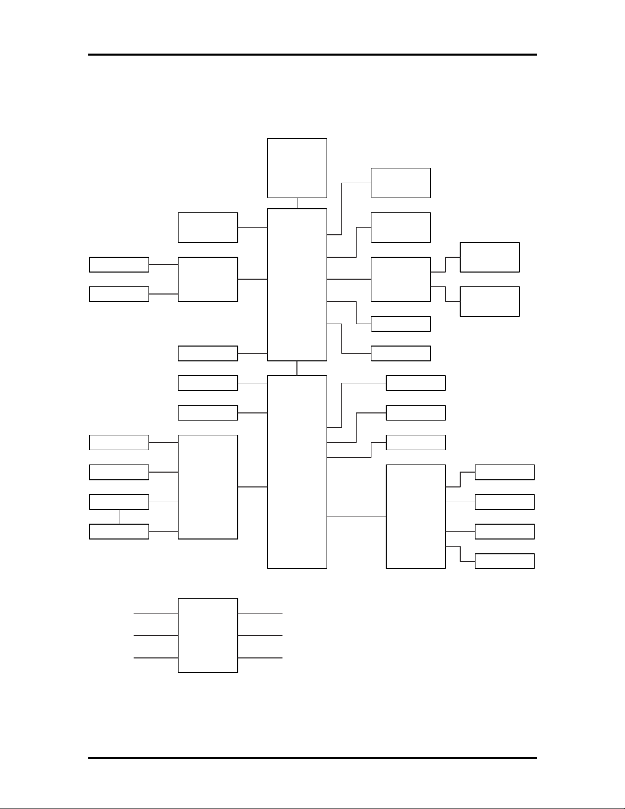
3-2 Hardware Functional Overview
FUNCTIONAL BLOCK DIAGRAM
The following figure shows the NEC Versa 2700 Series functional diagram.
CPU
Pentium MMX
P55C
Tillamook (TCP)
133/150/166/
200/233 MHz
Bank 1
so-DIMM
16/32/64 MB
CRT
LCD
PS/2 Mouse
Glide Pad
Internal Kb
External Kb
L2
Cache
256 KB
VGA
Neo Magic
NM2093
USB
Serial
FDD
Keyboard
Controller
M38813/M4
System PCB
430TX
MTXC
324BGA
Super I/O
NS87338VJG
Bank 2
so-DIMM
16/32/64 MB
PCMCIA
TI
1131
HDD
CD-ROM
Flash ROM
3.3V, 32PLCC
Battery
Printer
Audio PCB
Yamaha
715B
Slot 0
PCMCIA
Slot 1
PCMCIA
Headphones
Microphone
Line-In
Volume Control
Clock
Generator
Figure 3-1 Functional Block Diagram
Page 76

Hardware Functional Overview 3-3
SYSTEM BIOS
The primary function of the system BIOS (Basic Input-Output System) is to provide a series of software interrupts, functions, and sub-functions that control operations on certain
devices, such as the hard disk drive, the diskette drive, and the video subsystem.
The NEC Versa 2700 Series uses the AMIBIOS. The BIOS Setup program is an easy-touse system utility configuration that sets system parameters and copies them on the Flash
ROM chip with the system BIOS.
The Flash ROM chip also includes BIOS Power-On Self Test (POST) diagnostic and booting codes that tests the system components, initializes certain data structures, and boots the
operating system.
System Processor
The system processor function for the notebook is implemented on the system board using
an Intel MMX, P55C-133/150/166/200 or P55CLM-233/266 MHz processor chips. These
processor operate in conjunction with the RAM and ROM memory plus other system con-
e.g
trol logic (
tions).
.
Intel 430TX) to process software instructions (BIOS, Windows, applica-
The P55C microprocessor is a 2.8V desktop/2.5V mobile (the P55CLM is 1.8V) (3.3V I/O)
version of the Pentium processor (75-200). It is functionally similar to the Pentium
processor (75-200) with the following differences: Voltage supplies, maximum bus and core
frequency, and performance. The P55C/P55CLM is socket compatible with the Pentium
processor (75-200) making it possible to design a flexible motherboard that supports both
the Pentium processor (75-200) and the P55C/P55CLM processor. The P55C/P55CLM is
manufactured on an advanced CMOS process, which enables the P55C with a reduced core
voltage supply to run at up to 200 MHz core frequency (the P55CLM can run at up to 266
MHz core frequency.
The P55C/P55CLM, like the Pentium processor (75-200) has built-in arbitration and cache
consistency features for Dual-Processing (DP) which enable a “glueless” dual P55C system
design. The P55C/P55CLM can be configured in both modes, DP or uniprocessing.
The P55C/P55CLM has the complete Pentium processor (75-200) feature set, plus the
following new features:
16 KB 4-way set-associative code cache and 16 KB 4-way data cache, each with
improved fully associative TLBs.
Pool of 4 write buffers used by both pipes.
New Fetch pipeline stage between Prefetch and Instruction Decode with 4-deep
instruction FIFO.
Enhanced branch prediction algorithum.
Page 77

3-4 Hardware Functional Overview
Up to 233 Mhz/266 MHz core frequency operation for both desktop and mobile
systems.
Supports the Intel 430 chipset family. Does not support Intel 82497/82492 or
82498/82493 cache chipsets.
SYSTEM LOGIC CONTROLLER
The System Logic Controller function for the notebook is implemented on the system board
using Intel 430TX PCI Chipset. The 430TX PCIset consists of the TX System Controller
(MTXC) and the PCI ISA IDE Xcelerator (PIIX4). The PCIset forms a Host-to-PCI
bridge and provides the second level cache control and a full function 64-bit data path to
main memory. The MTXC integrates the cache and main memory DRAM control functions
and provides bus control to transfers between the CPU, cache, main memory, and the PCI
Bus.
The second level (L2) cache controller supports a write-back cache policy for cache sizes of
256 Kbytes and 512 Kbytes. Cacheless designs are also supported. The cache memory can
be implemented with pipeline burst SRAMs. An external Tag RAM is used for the address
tag and an internal Tag RAM for the cache line status bits.
For the MTXC DRAM controller, six rows are supported for up to 256 Mbytes of main
memory. The MTXC PCIset is highly integrated by including the Data Path into the same
BGA chip. Using the snoop ahead feature, the MTXC allows PCI masters to achieve full
PCI bandwidth. For increased system performance, the MTXC integrates posted write and
read prefetch buffers. The Intel 430TX PCIset integrates many Power Management features that will enable the system to save power whenever the system resources become idle.
Features Summary:
Supports the Pentium® processor family host bus at 66 MHz at 3.3V and 2.5V.
PCI 2.1 compliant
Integrated data path
Integrated DRAM controller
4 MB to 256 MB main memory
64 Mbit DRAM/SDRAM technology support
FPM (Fast Page Mode), EDO and SDRAM DRAM support
6 RAS lines available
Integrated Programmable-Strength for DRAM interface
CAS-Before-RAS Refresh, extended refresh and self refresh for EDO
CAS-Before-RAS and Self refresh for SDRAM
Page 78

Hardware Functional Overview 3-5
Integrated L2 Cache Controller
64MB DRAM cacheability
Direct Mapped Organization - Write Back Only
Supports 256K and 512K Pipelined Burst SRAM and DRAM cache
Cache Hit Read/Write cycle Timings at 3-1-1-1
Back-to-Back Read/Write Cycles at 3-1-1-1-1-1-1-1
64K x 32 SRAM also supported
Fully Synchronous, Minimum Latency 30/33 MHz PCI bus interface
Five PCI Bus Masters (including PIIX4)
10 DWord PCI-to-DRAM read prefetch buffer
18 Dword PCI-DRAM post buffer
Multi-Transaction Timer to support multiple short PCI transactions
Power Management Features
PCI CLKRUN# support
Dynamic Stop Clock support
Suspend to RAM (STR)
Suspend to Disk (STD)
Power On Suspend (POS)
Internal Clock control
SDRAM and EDO self refresh during suspend
ACPI Support
Compatible SMRAM (C-SMRAM) and Extended SMRAM (E_SMRAM)
SMM Write-Back cacheable in E_SMRAM mode up to 1 MB
3.3/5V DRAM, 3.3/5V PCI, 3.3/5V Tag, and 3.3/2.5V SRAM support
Test Features
NAND tree support for all pins
Supports the Universal Serial Bus (USB)
Page 79

3-6 Hardware Functional Overview
324-pin MBGA 430TX PCIset Xcelerated Controller (MTXC) with integrated
Data Paths
MEMORY SUBSYSTEM
The memory subsystem, implemented on the system board, includes ROM and DRAM
memory. Primary control for the memory subsystem is provided by the Intel 430TX PCIset.
DRAM Memory
The NEC Versa 2700 notebooks provides two memory slots for upgrading the DRAM
memory to 32 MB, 48 MB, 64 MB, 80 MB, and 128 MB using standard JEDEC or EDO
small-outline DIMM (SO-DIMM) memory modules.
Refer to “System Upgrades” in Chapter 1 to learn more about upgrading system memory.
ROM Memory
The NEC Versa 2700 Series notebooks contains both the main system BIOS and the VGA
BIOS with Shadow BIOS capability.
I/O SUBSYSTEM
The PC87338VLJ/PC87338VJG provides the most commonly used ISA, EISA, and
MicroChannel® peripherals in a single chip. It includes a Floppy Disk Controller (FDC),
two full function UARTs, Universal Infrared support (UIR) (HP-SIR, Sharp-IR, TVRemote, and Infrared Data Association (IrDA)), a full IEEE 1284 parallel port, two general
purpose chip select signals that enable game port control, and a configuration register set.
In addition, support for power management and for mixed 3.3V and 5V operation makes
this chip particularly suitable for notebook and sub-notebook applications.
The PC87338 provides full Plug and Play support as specified by Microsoft®.
Feature’s summary of the NC87336VLJ:
A special Plug and Play module includes:
Flexible IRQs, DMAs and base addresses
General Interrupt Requests (IRQs) that can be multiplexed to the ten sup-
ported IRQs
A new, high performance, on-chip Floppy Disk Controller (FDC) provides:
Software compatibility with the PC8477, which contains a superset of the
floppy disk controller functions in the µDP8473, the NECµPD765A and the
N82077
A modifiable 13-bit address
Page 80

Hardware Functional Overview 3-7
Ten IRQ channel options
Four 8-bit DMA channel option
16-Byte FIFO
Burst and non-burst modes
Low-power CMOS with enhanced power-down mode
A new, high-performance, on-chip, digital data seperator that does not require
any external filter components
Support for standard 5.25” and 3.5” diskette drives
Automatic media sense support
Perpendicular recording drive support
Three mode Diskette Drive (FDD) support
Full support for IBM’s Tape Drive Register (TDR) implementation
Support for new fast tape drives (2 Mbps) and standard tape drives (1 Mbps,
500 Kbps, and 250 Kbps)
Two UARTs provide:
Software compatibility with the 16550A and the 16450
A modifiable 13-bit address
Ten IRQ channel options
MIDI Baud rate support
Four 8-bit DMA channel options on UART2
Shadow register support for UART write-only bits
A slow infrared mode Universal Infrared (UIR) interface on UART2 supports the
following:
Data rates of up to 115.2 Kbps (SIR)
A data rate of 1.152 Mbps (MIR)
A data rate of 4.0 Mbps (FIR)
Selectable internal or external modulation/demodulation (Sharp-IR)
A bi-directional parallel port that includes:
A modifiable 13-bit address
Page 81

3-8 Hardware Functional Overview
Ten IRQ channel options
Four 8-bit DMA channel options
An Enhanced Parallel Port (EPP) compatible with version EPP 1.9
(IEEE1284 compliant), that also supports version EPP 1.7 of the Xircom
specification
An Extended Capabilities Port (ECP) that is IEEE 1284 compliant, including
level 2
Bi-directional data transfer under either software or hardware control
Compatibility with ISA, EISA, and MicroChannel parallel ports
Multiplexing of additional external FDC signals on parallel port pins that en-
ables use of an external Floppy Disk Drive (FDD)
A protection circuit that prevents damage to the parallel port when an external
printer powers up or operates at high voltages
14 mA output drivers
Two general purpose pins for two programmable chip select signals can be
programmed for game port control
An address decoder that:
Selects all primary and secondary ISA addresses, including COM1-4 and
LPT1-3
Decodes up to 16 address bits
Clock Source:
An internal clock multiplier generates all required internal frequencies.
A clock input source 14.318 MHz, 24 MHz, or 48 MHz may be selected
Enhanced power management features:
Special power-down configuration registers
Enhanced programmable FDC command to trigger power down
Programmable power-down and wake-up modes
Two dedicated pins for FDC power management
Low power-down current consumption (typically less than 10µA).
Reduced pin leakage current
Page 82

Low power CMOS technology
The ability to shut off clocks to either the entire chip or only to specific mod-
ules
Mixed voltage support provides:
Standard 5V operation
Low voltage 3.3V operation
Simultaneous internal 3.3V operation and reception or transmission to devices
that have either a 3.3V or a 5V power supply
100-pin TQFP package - PC87338VJG
100-pin TQFP package - PC87338VLJ
VIDEO SUBSYSTEM
Hardware Functional Overview 3-9
The video subsystem, implemented on the system board and on the LCD panel, controls the
display output to both the LED panel and to the external VGA port.
The NM2160 is a high performance Flat Panel Video Accelerator that integrates in one
single chip, 2 Mbytes of high speed DRAM, 24-bit true-color RAMDAC, Graphics/Video
Accelerator, Dual Clock Synthesizer, TV-Out support, ZV (Zoomed Video) port, Z-Buffer
Data Stripping, PCI Bus Mastering, and a high speed glueless 32-bit PCI 2.1 compliance
interface.
By integrating the display buffer DRAM and 128-bit graphics/video accelerator, the
NM2160 achieves the leading performance in the smallest footprint available. The NM2160
has sufficient bandwidth to perform full-screen, 30fps video acceleration of MPEG, Indeo,
Cinepak, and other video playback CODECs. The bandwidth headroom also allows the
NM2160 to deliver the highest quality video playback of any notebook graphics solution,
without compromising simultaneous graphics performance.
Feature summary of the NM2160:
128 Bit Graphics Acceleration
High speed BitBLT Engine
Color Expansion
Accelerated Text Hardware
Clipping
X - Y Coordinates Addressing
Memory Mapped I/O
Page 83

3-10 Hardware Functional Overview
Bus Mastering
Z - Buffer data stripping
VGA I/O Relocatable to MMIO Space
Video Acceleration
Integrated frame buffer for Video and Graphics
16 M Color video in all modes
Color Space Conversion (YUV to RGB)
Arbitrary video scaling up to 8X ratio
Bilinear interpolation and Filtering
Video Overlay capability from on/off screen memory
Chroma Key Support
Independent Brightness Control for Video Window
Supports different color depths between video and graphics
Supports RGB graphics and video in YUV format in one Integrated frame
buffer
Memory Support
High Speed 2 Mbytes of integrated DRAM
128 bit Memory Interface
Bus Support
PCI 2.1 compliance Loceal Bus (Zero wait states)
3.3Volts or 5Volts operation
EMI Reduction
Spread Spectrum Clocking technology for reduced panel EMI
Hardware Cursor and Icon
Relocatable Hardware Cursor and Icon
64 x 64 Hardware Cursor
Page 84

Hardware Functional Overview 3-11
64 x 64 or 128 x 128 Hardware Icon
Green PC Support
VESA Display Power Management (DPMS)
DAC Power Down modes
Suspend/Standby/Clock management
VGA disable support
PCI Mobile Computing “clockrun” support
Resolution and Color Support
VGA: TFT, DSTN, CRT @ 85Hz (640 x 480 256, 64K, 16M)
SVGA: TFT, DSTN, CRT @ 85Hz (800 x 600 256, 64K, 16M)
XGA: TFT, DSTN, CRT @ 75Hz (1024 x 768 256, 64K Colors)
Simultaneous CRT/Flat Panel operation
Simultaneous TV/Flat Panel operation
Display Enhancements
TV Out Support
ZV (Zoomed Video) Port
24 Bit Inegrated RAMDAC with Gamma Correction
36 bit panel support
Hardware expansion for low-resolution display mode compensation to panels
Virtual Screen Panning Support
Integrated Dual Clock Synthesizer
VESA DDC1 and DDC2b
External VGA Capability
The NEC Versa 2700 Series notebooks provide a 15-pin female D-type external VGA connector that can be connected to an external video graphics adapter (VGA) type monitor.
Page 85

3-12 Hardware Functional Overview
Another feature of the notebook computer is the ability to auto-sense the display output to
both LCD and the external CRT monitor. The notebook provides external resolution of
1024 x 768 by 64K colors for the NEC Versa 2700 Series with 2 MB video memory. The
NEC Versa 2700 Series can also provide simultaneous display at 800x600 at 64K colors
with the standard VGA DSTN LCD.
KEYBOARD SUBSYSTEM
The Keyboard Subsystem of the notebook is implemented on the I/O Board and Keyboard
Assembly using the Motorola M 38813M4 keyboard controller chip.
The NEC Versa 2700 Series keyboard is an 85-key, IBM enhanced-type keyboard with
standard characters and function keys plus 12 programmable function keys. The notebook
also provides an external PS/2 port for supporting an external PS/2 keyboard or standard
DIN-type AT-keyboard. See Section 1 for more information.
PCMCIA CONTROLLER AND SOCKETS
The PCMCIA controller is implemented on the system board using TI’s PCI-1131 Interface
Controller.
The TI PCI-1131 is a high-performance PCI-to-PCI Card controller that supports two
independent PC Card sockets compliant with the 1995 PC Card standard. The PCI-1131
provides a set of features that make it ideal for bridging between PCI and PC Cards in both
notebook and desktop computers. The PCI-1131 supports any combination of 16-bit and
CardBus PC Card bus-mastering in its two sockets, powered at 3.3V or 5V, as required.
The PCI-1131 is compliant with the PCI local bus specification revision 2.1, and its PCI
Interface can act as either a PCI master device or a PCI slave device. The PCI bus
mastering is initiated during 16-bit PC Card DMA transfers or CardBus PC Card busmastering cycles.
All card signals are internally buffered to allow hot insertion and removal without external
buffering. The PCI-1131 is register compatible with the Intel 82365SL-DF ExCA
controller. The PCI-1131 internal datapath logic allows the host to access 8-, 16-, and 32bit cards using full 32-bit PCI cycles for maximum performance. Independent 32-bit write
buffers allow fast-posted writes to improve system-bus utilization.
An advanced CMOS process is used to achieve low system-power consumption while
operating at PCI clock rates up to 33 MHz. Several low-power modes allow the host
power-management system to further reduce power consumption.
Feature summary of the TI PCI-1131:
3.3V Core Logic with Universal PCI Interface Compatible with 3.3V or 5V PCI
signaling environments
Supports PCI Local Bus Specification 2.1
Page 86

Hardware Functional Overview 3-13
Mix-and-Match 3.3-V/5-V PC Cards and 3.3-V CardBus Cards
Supports two PC Card™ or CardBus Slots with Hot Insertion and Removal
1995 PC Card-Standard Compliant
Low-Power Advanced Submicron CMOS technology
Uses Serial Interface to Texas Instruments (TI) TPS2206 Dual Power Switch
System interrupts can be programmed as PCI-Style of ISA IRQ-Style interrupts
ISA IRQ interrupts can be serialized onto a Single IRQSER pin
Programmable Output Select for CLCKRUN
Supports Burst transfers to maximize data throughput on the PCI and CardBus
Bus
Multifunction PCI Device with separate configuration spaces for each socket
Five PCI Memory Windows and Two I/O Windows available to each PC Card16
Socket
Two I/O Windows and Two Memory Windows Available to each CardBus
Socket
CardBus Memory Windows can be individually selected prefetchable or non-
prefetchable
Exchangeable Card Architecture (ExCA™)-Compatible registers mapped in
Memory or I/O space
TI Extension Registers mapped in the PCI Configuration space
Intel 82365SL-DF Register compatible
Supports 16-bit Distributed Direct Memory Access (DMA) on both PC Card
sockets
Supports PC/PCI DMA on both PC Card sockets
Supports Zoom Video mode
Supports Ring Indicate
Packaged in 208-pin Thin Plastic Quad Flatpack
Page 87

3-14 Hardware Functional Overview
HARD DISK SUBSYSTEM
The hard disk subsystem, implemented on the system board and on the associated built-in
hard disk drive, provides disk storage for all system software and user files.
The NEC Versa 2700 Series notebook is equipped with a high capacity hard disk drive that
provides LBA (Logical Block Addressing) mode support. The I/O subsystem controller, NS
PC87338CLJ, provides the IDE controller for the hard disk.
The built-in controller can support any industry standard 2.5-inch IDE hard disk drive. Setting up the hard disk type is done automatically by the CMOS Setup program. Setup autodetects the installed hard disk type settings for optimized performance.
NOTE:
LED is activated. This protects the hard disk drive
from any accidental damage or loss of data.
Do not move the notebook when the HDD
DISKETTE DRIVE SUBSYSTEM
The diskette drive subsystem consists of a FDD controller provided by Super I/O
PC87338VLG and the built-in diskette disk drive. The diskette disk drive supports standard
3.5-inch; 720 KB and 1.44 MB mini-diskettes.
POINTING DEVICE SUBSYSTEM
The pointing device subsystem consists of the VersaGlide device on the system Palm Rest
cover assembly, and a pre-programmed Mitsubishi M38813M4 micro-controller that interfaces the mouse device to the system board. An external PS/2 port also supports the use of
an external PS/2 compatible mouse which the system automatically detects during system
power up and then disables the internal VersaGlide.
POWER SUBSYSTEM
The Power Subsystem consists of the following major sections:
External AC Power Adapter
Internal Battery Pack
Power Board (on system board)
LCD Inverter Board (in LCD Panel Assembly)
Power Conservation Logic (part of system board)
Page 88

Hardware Functional Overview 3-15
AC Power Adapter
The computer is equipped with a universal AC power adapter that converts AC voltage (90
to 265VAC, 47 to 63Hz) into DC voltage used to operate the notebook and charge the
batteries.
Internal Battery Pack
The NEC Versa 2700 Series notebooks utilizes NiMH (Nickel Metal-Hydride) or Li-Ion
(Lithium Ion) batteries that provide DC power for the notebook.
The NiMH battery pack contains eight size A battery cells that provide the system with
9.6V and the Li-Ion battery pack contains eight size A battery cells that provide the system
with 14.4V. When installed in the notebook, the battery LED automatically appears and
also starts to recharge whenever the AC adapter is connected to the notebook.
Normal charging time for the battery pack is around 2 hours when the computer is turned
off while it should take around 4 hours maximum when the computer is running.
Power Board
The power board receives approximately 12VDC from the battery pack and uses this input
voltage to generate +12V, +5V, +3.3V, (+3.45V) regulated output voltages to provide
power for all internal notebook board assemblies. The output of the +5V regulator also
drives the LCD inverter circuit on the LCD inverter board assembly. Refer to Section 2 for
more detailed information.
LCD Inverter Board Assembly
The LCD Inverter Board Assembly, located in the LCD Panel Assembly, converts the
+5VDC input from the Power Board module of the system board into a high voltage AC
output used to light the CCFT (Cold-Cathode Fluorescent Tube).
Page 89

Section 4
Troubleshooting and Repair
This section focuses on providing you with some information on notebook basic troubleshooting as well as the BIOS POST error codes and messages.
SERVICE INFORMATION
NEC service and information telephone numbers are listed in the following table.
Table 4-1 NECCSD Service and Information Telephone Numbers
Service Call
To order NECCSD spare parts In the U.S., call 1(800) 632-4525
To order options in the U.S. Local Sales Office
To access the NECCSD Electronic Bulletin
Board System (BBS)
To download files - provides software drivers
and the latest ROM BIOS
NECCSD Customer Service and Technical
Support Center
NECCSD Customer Assistance Center for
customer service, extended warranties, and
contracts
FaxFlashSM - automated fax service that
sends the latest information about NEC
products to the fax machine 24 hours a day
1(978) 635-4706
1(978) 635-4706
In the U.S., call 1(800) 632-4525
In the U.S., call 1(888) 632-9128
In the U.S. and Canada, call 1(888) 3290088
Outside U.S. 1 (978) 635-6090
TECHNICAL SUPPORT
NECCSD Technical Support Center (TSC) provides an E-mail service for Internet users.
Technical questions regarding NEC products can be sent over the Internet system to TSC.
The Internet address is as follows:
If it is more convenient, questions may also be faxed to TSC. The fax number is:
(978) 635-4100
Along with the complete product name and question(s), be sure to included your name and
fax number or Internet address, so that an expert can respond to your question(s).
Page 90

4-2 Troubleshooting and Repair
It would also be helpful to include your telephone number in case TSC can not get their answer to you through the Internet or by fax. TSC replies to all questions received by Internet
or fax within one business day.
PRODUCT INFORMATION
NECCSD FaxFlash is a self-help, automated electronic information service for obtaining
up-to-date product application notes, installation procedures, troubleshooting tips, data
sheets, technical information bulletins, illustrated parts lists, part numbers, and other information about your system.
Using a fax machine, you can obtain information from FaxFlash 24 hours a day, 7 days a
week. You simply call the FaxFlash number on your touch-tone telephone and order the
information you want by following the voice prompts. FaxFlash will automatically fax the
information to you.
If you are new to FaxFlash, you should first order one of the following catalogs. Each
catalog lists the available documents and their document numbers. Current catalogs include:
Catalog 1, Telephone Directory and information about Online Services.
Catalog 3, Product specifications, warranty policy, Ultracare guidelines, and sales
information.
Catalog 5, Pro Serva and Express Server Systems technical support information.
Catalog 6, NEC Ready Systems technical support information.
Catalog 7, PowerMate Systems technical support information.
Catalog 8, NEC Portable Systems (including Versa Notebooks and MobilePro
Handheld Personal Computers) technical support information.
Technical support information includes BBS and FTP file listings, Illustrated Parts
Breakdowns (IPB), part numbers, frequently asked questions (FAQ) lists, and
other documents specific to each product.
Order information from FaxFlash as follows:
Be sure that your fax machine or fax/modem is on. Have the document number
1.
ready for the document you want, if you already know the number.
From your touch-tone telephone, enter 888-329-0088 (U.S. and Canada only).
2.
For international use, enter the international long-distance access number, the
U.S. country code, and the U.S. telephone number (978-635-6090).
Listen to the instructions provided by the voice prompts.
3.
Press 1 if you do not want an introduction to FaxFlash. Follow the automated instructions for ordering your document or catalog.
Page 91

Troubleshooting and Repair 4-3
Press 2 if you want an introduction to FaxFlash. Follow the automated instructions for ordering your catalog or document.
When prompted, enter your fax number and name.
4.
For international use, first enter the international long-distance access number
(011), your country code, your area code or city code, then your fax number.
The information you requested is automatically sent to your fax machine. Wait for the ordered document to arrive at your fax machine before calling to order more documents. If
FaxFlash attempts to send the second order before the first order is completed, the order
may be canceled. After three tries, FaxFlash assumes that your line is busy and terminates
any further processing of the order.
HELPFUL STARTERS
Here are some helpful items to check before troubleshooting the notebook:
Is there any external power source connected to the computer?
Has the battery been fully charged?
Is the computer turned on and the POWER LED activated?
Is the LCD display control switch moved to its minimum level?
Is the LCD display switched to the external monitor?
Are all cables and devices connected properly and securely?
Have all needed device drivers been installed properly?
Have you checked the AUTOEXEC.BAT and CONFIG.SYS files for errors?
Is the Suspend mode activated (LED Status Bar)? Press the suspend button to
wake up the system again.
Page 92

4-4 Troubleshooting and Repair
y
y
y
g
y
y
y
g
g
y
g
y
y
POWER-ON SELF TEST (POST)
This section provides you with the AMI BIOS POST errors and messages summary. Refer
to this whenever you encounter error messages or beep codes generated by the computer
during startup.
POST Messages
The following is a summary of the AMI BIOS startup error messages that are displayed on
the notebook’s display. These messages will help you to understand many of the notebook’s
problems that may be corrected by entering the CMOS SETUP program and checking the
original values.
Table 4-2 POST Error Messages
Message Possible Cause Action
Diskette drive A failure The drive failed or is
missing.
Diskette read failure -
F1
press
for SETUP utility
No display message,
s
adapter fails,
Gate A20 failure The keyboard controller is
Fixed disk configuration
error
Fixed disk controller
failure
Fixed disk read failurepress
for SETUP utility
to retry boot,
stem will beep when
F1
to retry boot,
The diskette is either not
F2
formatted or is defective.
The primar
failed.
not acceptin
specificall
and disable A20
command.
The specified
confi
supported or doesn't
match the actual hardware
installed.
The fixed disk may be
defective.
The fixed disk ma
F2
confi
defective.
, the enable
uration is not
ured incorrectly or is
video adapter
command,
be
Check the drive to determine
the problem.
Replace the diskette with a
bootable diskette and retr
Check the primary video
adapter.
Check the ke
controller and s
Turn the power off, then back
ain. If the problem
on a
persists contact qualified
NEC service personnel.
Correct the fixed disk
configuration.
Try rebooting. If that doesn't
work, replace the fixed disk.
Check the drive t
in SETUP. Tr
that does not work, replace
the fixed disk.
board
stem board.
pe selected
rebooting. If
.
Pointer device failure The PS/2-style mouse
failed.
Try rebooting. If problem
persists, check the mouse,
it's cable and connector.
Page 93

Troubleshooting and Repair 4-5
y
y
y
g
g
g
y
y
g
g
y
y
g
Table 4-2 POST Error Messages (cont’d)
Message Possible Cause Action
No boot device available press
F1
to retry boot,
F2
for SETUP utility
Either diskette drive A:,
the fixed disk, or both the
diskette and fixed disk are
rebooting. If the problem
Tr
persists, replace the diskette
or the fixed disk.
defective.
No boot sector on fixed
F1
disk - press
to retr
boot, F2 for SETUP utility
Not a boot diskette - press
F1
to retry boot, F2 for
SETUP utility
The C: drive is not
formatted or is not
bootable.
The diskette in drive A: is
not formatted as a
bootable diskette.
Format the C: drive and
make it bootable.
Replace the diskette with a
bootable diskette and tr
rebooting.
No timer tick interrupt The timer chip has failed. Check the system board,
Turn the power off, then back
ain. If the problem
on a
persists, contact qualified
service personnel.
Shutdown failure Either the keyboard
controller is not acceptin
the reset command or the
associated reset lo
failed.
ic has
Check the ke
controller and s
Turn the power off, then back
ain. If the problem
on a
persists, contact qualified
board
stem board.
service personnel.
Time of day not set - run
SETUP program
Real Time Clock is not
set.
Run SETUP utility.
Timer 2 failure The timer chip has failed. Check the system board.
Turn the power off, then back
ain. If the problem
on a
persists, contact qualified
service personnel.
F2 to enter ROM-based
SETUP
Invalid configuration
information - please run
SETUP
Invalid configuration
information must be
changed.
Displa
adapter is
configured incorrectly.
Memory size is incorrect.
number of diskette
Wron
You must run SETUP utilit
and correct configuration
information.
Run the SETUP utility.
drives.
Page 94

4-6 Troubleshooting and Repair
y
y
y
y
y
y
y
g
y
g
y
y
y
g
y
g
y
Table 4-2 POST Error Messages (cont’d)
Message Possible Cause Action
Keyboard clock line failure The keyboard, the
board cable
ke
connection, or the
board controller is
ke
defective.
Keyboard data line failure The keyboard controller
firmware has failed.
Keyboard stuck key failure A key is jammed. Locate the jammed key and
Memory failure at
value
, read
expecting
hex-value
hex-
hex-value
Circuitry associated with
,
the memor
failed.
chips has
Make sure the ke
cable and ke
connected properl
the ke
the s
power off, then back on
a
contact qualified service
personnel.
Check the keyboard
controller and s
Turn the power off, then back
on a
persists, contact qualified
service personnel.
fix it. Make sure the ke
cable and ke
connected properl
power off, then back on
a
contact qualified service
personnel.
Turn the power off, then back
on a
persists, contact qualified
service personnel.
board controller and
stem board. Turn the
ain. If the problem persists,
ain. If the problem
ain. If the problem persists,
ain. If the problem
board
board are
. Check
stem board.
board
board are
. Turn the
Unexpected interrupt in
protected mode
Real time clock failure The RTC or battery failed. Run SETUP and turn the
Hardware interrupt or NCI
occurred while in
protected mode.
Check the timer chip or the
interrupt controller on the
system board.
power off and on. If the
problem persists, replace the
RTC batter
remains, contact qualified
service personnel.
. If the problem
Beep Codes
Fatal errors that occur during POST are communicated through a series of beeps. All beep
code errors, except beep code 8, are fatal errors and do not allow the system to continue to
boot.
Page 95

Troubleshooting and Repair 4-7
y
y
y
y
g
If beep codes occur during POST, check the items in the Problem Checklist (at the start of
this chapter), verify that all the hardware is set up properly and securely connected, and try
rebooting. If you still get a beep code, go to the section “If You Need Assistance” at the
end of this chapter.
Beep Codes are listed in the table that follows.
Table 4-3 Beep Codes
Number of
Beeps
1 Refresh Failure The memory refresh circuitry on the
2 Parity Error Parity error in the first 64 KB of memory.
3 Base 64 KB Memor
4 Timer Not Operational Memory failure in the first 64 KB of
5 Processor Error The CPU on the motherboard generated
6 Gate A20 Failure The keyboard controller may be bad.
7 Processor Exception
8 Display Memor
Error Description
motherboard is faulty.
Memory failure in the first 64 KB.
Failure
or Timer 1 on the motherboard
stem video adapter is either
or its memory is faulty. (This is
Interrupt Error
Read/Write Error
memor
is not functioning.
an error.
The BIOS cannot switch to protected
mode.
The CPU generated an exception
interrupt.
The s
missin
not a fatal error.)
9 ROM Checksum Error The ROM checksum value does not
match the value encoded in the BIOS.
10 CMOS Shutdown Register
Read/Write Error
11 Cache Error/External
Cache Bad
The shutdown register for CMOS RAM
failed.
The external cache is faulty.
Page 96

4-8 Troubleshooting and Repair
y
g
y
g
y
g
g
y
Informational Messages
This section lists the messages that provide information to the user but require no action.
Table 4-4 BIOS Informational Messages
Message Meaning
NCH
Base Memory The amount of base memory that tested successfully.
NCH
Extended The amount of extended memory that tested
successfully.
Memory tests terminated b
keystroke
Press the F1 key to continue This message indicates that an error was found durin
Beginning memory test Press
SPACEBAR
the
memory test
Press the F1 key to continue,
to run the Setup utility
to terminate the
The messa
spacebar while memor
stopped the memory tests.
POST. Pressing the F1 key allows the system to
attempt to reboot.
A user can stop the memor
spacebar.
F2
This messa
POST. Pressing the
attempt to boot. Press
ROM-based SETUP utilit
information.
e indicate that a user pressed the
tests were running and
tests by pressing the
e indicates that an error was found durin
F1
key allows the system to
F2
allows users to run the
to correct configuration
Page 97

Troubleshooting and Repair 4-9
y
y
y
y
y
y
y
y
g
g
Run-time Error Messages
The following table lists run-time error messages.
Table 4-5 Run-time Error Messages
Message Cause Action
I/O card parity interrupt at
address
NCI, (R)eboot, other ke
continue
Memory parity interrupt at
address
NCI, (R)eboot, other ke
continue
Unexpected HW interrupt,
interrupt at address. T
(R)eboot, other ke
continue
Unexpected SW interrupt,
interrupt at address
(R)eboot, other ke
continue
. Type (S)hut off
. Type (S)hut off
pe
s to
. Type
s to
s to
s to
Memor
has failed.
A memor
memory card has failed.
Hardware problem. Not
displa
interrupt handler is not
enabled.
Error(s) in the software
pro
extended interrupt handler is
not enabled.
on a peripheral card
chip(s) on a
ed if the expected
ram. Not displayed if the
Check the memory cards
installed in the system.
Replace the memory card.
Replace the system board.
Check all hardware in the
system.
Turn the machine off and
then on a
work, check the program.
ain. If it doesn’t
Page 98

4-10 Troubleshooting and Repair
y
gg
y
y
y
y
y
y
y
g
QUICK TROUBLESHOOTING
This section summarizes problems that may develop during system operation and lists suggested corrective actions.
Table 4-6 Quick Troubleshooting
Problem Corrective Actions
No power Check that the AC adapter is plugged into the
power connector of the s
adapter is plu
power outlet.
If using the battery as main power source, check
if the batter
and is inserted correctly.
Check the power board of the system. Is it
inserted into the s
properly? Otherwise, replace the power board.
ed into a properly grounded AC
pack is of the right type, charged
stem board connector
stem. Also, that the AC
Data on the LCD is unreadable Adjust the brightness and contrast displa
controls found on the right side of the LCD panel.
Check if the LCD cables are inserted properl
Check also connections inside the LCD panel.
Check if installed VGA driver is correct.
Check VGA controller chip on the s
if there is any cold or loose soldering.
Replace the system board.
LCD screen does not show data Check the LED Status Bar if Suspend mode is
activated. Press an
button to resume operation and display.
Check if LCD cables are disconnected or loose.
Check if the displa
external monitor.
Check if the Contrast level is set to minimum.
Check if there is power.
Check if the SW51 Jumper settin
correct.
Replace LCD Inverter board found inside the
LCD Panel.
key or press the power
output is switched to the
stem board
mode is
.
Page 99

Troubleshooting and Repair 4-11
g
y
y
Table 4-6 Quick Troubleshooting (cont’d)
Problem Corrective Actions
Battery Power does not last Make sure that the power management features
are enabled.
Rechar
using again.
Replace the battery pack.
System halts during boot sequence Check condition of selected bootload device
(diskette or hard disk) for bad boot track or
incorrect OS files.
Tr
recopy or repartition hard disk.
Check for any BIOS error messages on the
display screen.
Replace the system board.
I/O processing malfunctions Check the connections of all internal devices.
e the battery pack for 1½ hour before
booting from a new bootable diskette and
Replace the system board.
Diskette drive does not work Check if the diskette drive cable is connected
properly.
Check the diskette type if correct and not faulty.
Replace the diskette drive.
Replace the system board.
Hard disk drive malfunction Check if hard disk drive is set properly on CMOS
SETUP.
Check the drive cables and connections.
Check if the disk drive is good.
Replace the system board.
Memory malfunction Check if the memory module is inserted properly.
Replace the memory module.
Replace the system board.
External keyboard or PS/2 mouse
doesn’t work
Check if keyboard or mouse are connected
properl
off system first before plugging in the device.
Replace the keyboard or mouse.
Replace the system board.
. Check Y-cable if it is being used. Power
Page 100

4-12 Troubleshooting and Repair
y
y
g
y
y
y
y
Table 4-6 Quick Troubleshooting (cont’d)
Problem Corrective Actions
PCMCIA card does not work Check the PCMCIA driver installation for an
IRQ or IO address conflict.
Check if the PCMCIA card is inserted properl
and all connections are set.
Replace the PCMCIA card.
Check for work around for the card bein
Replace the system board.
Serial device does not work Check if the serial device is connected properly.
Replace the serial device.
Check the I/O controller chip on the s
board for an
Replace the system board.
Parallel device does not work Check if all connections are properly set.
Check if the Port is enabled in Setup.
Check if external device is turned on.
Check I/O controller chip on the s
cold or loose soldering.
an
Replace the system board.
cold or loose soldering.
used.
stem
stem board for
 Loading...