

Page 1
NEC Solutions (America), Inc.
Visual Systems
VT470/570/575/670/676 Installation Guide
Ceiling Mounted and Desktop v1.5
Contents
Product Description, Lens Specs, Notes and Formulas Pg. 1
Diagrams and Distance Charts
Cabinet Dimensions
Ceiling Mount Dimensions
Input Panel and Control Codes
Product Description
Type: 3 panel LCD projector, Brightness: VT470: 2000 ANSI lumens
0.7” p-Si TFT (VT670 w/MLA) VT570: 1300 ANSI lumens
Resolution: VT470: 800x600 VT575: 1500 ANSI lumens
VT570/575/670/676: 1024x768 VT670: 2100 ANSI lumens
Dimensions: 11.57”(W) x 4.43”(H) x 11.10”(D) VT676: 2500 ANSI lumens
Weight: 6.4 lbs
Lens Specifications
Throw Ratio: 1.5 - 1.8:1(for 100” diagonal) Focal Length: 21.6mm – 25.9mm
Offset Angle: 9.6°-11.5°
Screen Sizes: 21”-300” diagonal (4:3) Manual Zoom / Manual Focus
(for 100” diagonal) F/#: 1.7 – 2.0
Notes
For screen sizes not indicated on the projection charts, use the formulas below.
If a value in a chart does not match the results of the formulas, use the values in the chart.
The ceiling must be strong enough to support the projector and the installation must be in accordance with any local
building codes.
All formulas are based on a 4:3 aspect ratio and screen.
Distances are in inches, for millimeters multiply by 25.4.
Distances may vary ±5%.
Formulas
The Projection Formulas use the image width for calculation. Image width is the same for all aspect ratios, only vertical image size
varies. For proper projector placement, determine the image width for a desired screen size. Use the Screen Formulas below to
calculate all screen dimensions. Plug in the image width for “W” in the Projection Formulas.
Refer to the diagrams and charts for popular screen sizes on page 2.
Definitions: 4:3 Screen Fo rmu las:
W = Image Width W = H x 4/3
H = Image Height (Size) H = W x 3/4
B = Vertical distance between lens center and screen center Screen Diagonal = W x 5/4
C = Throw distance
D = Vertical distance between lens center and screen top (screen
bottom for desktop)
α = Projection angle
Projection Formulas:
B = 0.2986W
C (wide) = 1.4813W – 1.425
C (tele) = 1.7913W – 1.406
D = 0.0764W
α (wide) = tan
α (tele) = tan
-1
-1
(B/C(wide))
(B/C(tele))
Pg. 2
Pg. 3 - 4
Pg. 5
Pg. 6
www.necvisualsystems.com VT470/570/575/670/676 Page 1 of 6
Page 2
Diagrams and Distance Charts
-
-
-
-
-
-
-
-
-
-
-
-
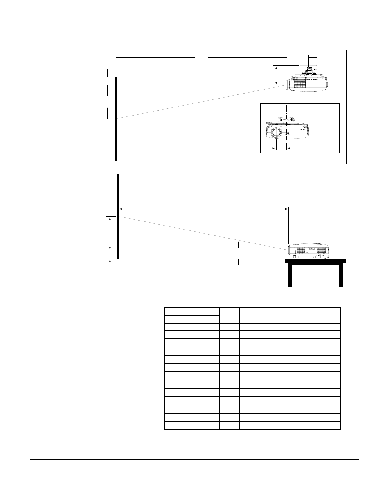
The following diagrams show the relationship bet ween projector position and the screen. Refer to the chart below for data.
Distances are in inches. For millimeters multiply by 25.4.
Ceiling
Mounted
Screen Top
D
Lens Ctr
C
Throw Distance
6.1"
5.5"
α
Screen Ctr
B
Lens Offset from
Mount Pipe
2.7"
Desktop
Screen Ctr
B
Lens Ctr
Screen Bottom
D
Distance chart for popular 4:3 screens
Note: For screen sizes not indicated on the chart,
use the formulas on page 1.
Note: “NA” means it is outside lens range for that
part of the zoom. Refer to “Screen Sizes” in Lens
Specifications on Page 1.
Screen Size
Diag W H wide
inches inches inches inches inches
21 16.8 12.6 5.0 NA-28.7 1.3 NA-9.9
60 48 36 14.3 69.7
72 57.6 43.2 17.2 83.9
84 67.2 50.4 20.1 98.1
90 72 54 21.5 105.2
100 80 60 23.9 117.1
120 96 72 28.7 140.8
150 120 90 35.8 176.3
180 144 108 43.0 211.9
200 160 120 47.8 235.6
250 200 150 59.7 294.8
300 240 180 71.7 354.1
www.necvisualsystems.com VT470/570/575/670/676 Page 2 of 6
C
Throw Distance
(4:3)
α
2.5"
BD
C
α
tele wide-tele
inches
degrees
84.6 3.7 11.6-9.6
101.8 4.4 11.6-9.6
119.0 5.1 11.6-9.6
127.6 5.5 11.5-9.6
141.9 6.1 11.5-9.6
170.6 7.3 11.5-9.5
213.6 9.2 11.5-9.5
256.5 11.0 11.5-9.5
285.2 12.2 11.5-9.5
356.9 15.3 11.5-9.5
428.5 18.3 11.4-9.5
Page 3

Cabinet Dimensions
The following drawings show the cabinet dimensions.
Dimensions are in inches. For millimeters multiply by 25.4.
www.necvisualsystems.com VT470/570/575/670/676 Page 3 of 6
Exhaust
10.24
2.81
11.57
4.15
11.10
4.19
(boss)
2.30
4.43
(foot)
2.54
Page 4

Cabinet Dimensions (continued)
The following drawings show the cabinet dimensions.
Dimensions are in inches. For millimeters multiply by 25.4.
www.necvisualsystems.com VT470/570/575/670/676 Page 4 of 6
3-M4x8 MAX For Ceiling Mount
Intake
6.852.61
1.83
3.60
7.28
For handle (Except VT570)
Lamp
Page 5

Optional Ceiling Mount Dimensions (Model #: VT70CM)
The following drawings show ceiling mount dimensions.
Dimensions are in inches. For millimeters multiply by 25.4.
www.necvisualsystems.com VT470/570/575/670/676 Page 5 of 6
7.62
2.67
7.62
3.24
Page 6

Input Panel
VIDEO IN L/MONO R COMPUTER 1 IN AUDIO COMPUTER 2 IN
S-VIDEO IN L/MONO R AUDIO OUT MONITOR OUT PC CONTROL
AUDIO
AUDIO
Control Codes
Function Code Data
POWER ON 02H 00H 00H 00H 00H 02H
POWER OFF 02H 01H 00H 00H 00H 03H
INPUT SELECT COMPUTER 1 02H 03H 00H 00H 02H 01H 01H 09H
INPUT SELECT COMPUTER 2 02H 03H 00H 00H 02H 01H 02H 0AH
INPUT SELECT VIDEO 02H 03H 00H 00H 02H 01H 06H 0EH
INPUT SELECT S-VIDEO 02H 03H 00H 00H 02H 01H 0BH 13H
PICTURE MUTE ON 02H 10H 00H 00H 00H 12H
PICTURE MUTE OFF 02H 11H 00H 00H 00H 13H
SOUND MUTE ON 02H 12H 00H 00H 00H 14H
SOUND MUTE OFF 02H 13H 00H 00H 00H 15H
NOTE: Contact your NEC rep for codes not listed.
Cable Connection
Communication Protocol: PC Control Connector (DIN-8P)
Baud Rate: 19200 bps
Data Length: 8 bits
Parity: No Parity
Stop Bit: One bit
X on/off: None
Communications: Full duplex
NOTE 1: Pins 2, 3, 5, 6 and 8 are used inside the projector..
NOTE 2: For long cable runs it is recommended to set communication speed within projector menus to 9600 bps.
To RxD of PC
678
345
12
To TxD of PCTo GND of PC
www.necvisualsystems.com VT470/570/575/670/676 Page 6 of 6
 Loading...