

Page 1

NIVERGE NEAX 2000 IPS
U
INTERNET PROTOCOL SERVER
Request For Proposal (RFP)
Reference Guide
May 2006
Page 2

NEC Unified Solutions, Inc.
LIABILITY DISCLAIMER
NEC Unified Solutions, Inc. reserves the right to change the specifications, functions, or
features, at any time, without notice.
NEC Unified Solutions, Inc. has prepared this document for use by its employees and
customers. The information contained herein is the property of NEC Unified Solutions, Inc. and
shall not be reproduced without prior written approval from NEC Unified Solutions, Inc.
UNIVERGE
a registered trademark of Microsoft Corporation. Intel
®,
NEAX® and Dterm® are registered trademarks of NEC Corporation. Microsoft® is
®
is a registered trademark of Intel
Corporation. All other product references and/or company references are registered
trademarks or trademarked for their respective products and/or company.
The UNIVERGE NEAX 2000 IPS Request For Proposal (RFP) Reference Guide has been
developed to provide technical information on the UNIVERGE NEAX 2000 IPS, which is
required when responding to the majority of questions asked on Request For Proposals. The
information provided has been compiled from a variety of available documentation and has
been consolidated into a single manual. For this reason, it may be necessary to gather
additional information from other supporting documentation to fulfill the Request For Proposal
(RFP) requirements.
Information concerning questions not covered in this guide, corrections and/or comments are
most welcome and should be sent to:
NEAX2000@necunifiedsolutions.com
NEC Unified Solutions, Inc.
UNIVERGE NEAX 2000 IPS Product Management
6555 North State Highway 161
Irving, TX 75039-2402
http://www.necunifiedsolutions.com
Copyright 2006
NEC Unified Solutions, Inc.
Printed in the U.S.A
Page 3

Chapter 1 Introduction.......................................................................................................................................... 1
Overview of NEC ...................................................................................................................................1
Components ..........................................................................................................................................3
Communications ....................................................................................................................................4
Social Contributions...............................................................................................................................4
Global Resources ..................................................................................................................................4
NEC Unified Solutions, Inc. ...................................................................................................................6
Vertical Markets .....................................................................................................................................8
Competitive Benefits and Advantages...................................................................................................8
UNIVERGE NEAX 2000 IPS ...............................................................................................................11
UNIVERGE NEAX IPS DM..................................................................................................................14
UNIVERGE NEAX IPS DML................................................................................................................15
UNIVERGE NEAX IPS DMR ...............................................................................................................15
Stand Alone System Capacity .............................................................................................................17
IP Remote Network Capacity...............................................................................................................23
Chapter 2 System Architecture............................................................................................................................ 1
Hardware Architecture ...........................................................................................................................1
UNIVERGE NEAX 2000 IPS System Configuration ..............................................................................4
UNIVERGE NEAX IPS DM/IPS DML/IPS DMR System Configuration ...............................................11
Software Architecture ..........................................................................................................................15
Chapter 3 System Highlights................................................................................................................................ 1
Processors.............................................................................................................................................1
Reliability and Availability ......................................................................................................................4
System Traffic........................................................................................................................................8
System Specifications..........................................................................................................................16
System Compliance.............................................................................................................................23
Chapter 4 Equipment List..................................................................................................................................... 1
Module/Installation Hardware ................................................................................................................1
Circuit Cards ..........................................................................................................................................3
Chapter 5 Station Equipment............................................................................................................................... 1
Terminal Line Up ...................................................................................................................................1
Analog Terminals...................................................................................................................................2
Dterm Series i (IP) Terminals ................................................................................................................3
Dterm Series i (TDM) Multi-line Digital Terminals..................................................................................5
Dterm Series E (Multi-line Digital Terminals).........................................................................................8
Dterm Cordless Terminals ...................................................................................................................15
INASET................................................................................................................................................18
Dterm PS III Wireless Handset ............................................................................................................20
Dterm SP30 SoftPhone .......................................................................................................................21
Dterm Extenders..................................................................................................................................26
Chapter 6 Trunking................................................................................................................................................ 1
Type of Trunks.......................................................................................................................................1
Trunk Card Specifications......................................................................................................................2
System Trunking Capacity.....................................................................................................................6
Least Cost Routing (LCR)......................................................................................................................8
Chapter 7 Attendant Answering Position ........................................................................................................... 1
Attendant Console (SN716)...................................................................................................................1
Business Attendant System (BAS) ........................................................................................................8
UNIVERGE NEAX 2000 IPS Request for Proposal (RFP) Reference Guide Page i
Issue 6
Page 4

Chapter 8 System Administration........................................................................................................................ 1
System Administration ...........................................................................................................................1
Customer Administration Terminal (CAT)..............................................................................................1
Maintenance Administration Terminal (MAT) ........................................................................................2
System Diagnostics ...............................................................................................................................5
Self Diagnostic/System Messages ........................................................................................................5
Remote Maintenance.............................................................................................................................5
MP Program Download..........................................................................................................................6
MA4000 Management System ..............................................................................................................8
Chapter 9 Feature Descriptions........................................................................................................................... 1
Business/Hotel/Data Feature List ..........................................................................................................1
Business/Hotel/Data Feature Descriptions ............................................................................................5
CCIS Feature List ................................................................................................................................34
CCIS Features Descriptions ................................................................................................................35
ISDN Feature List ................................................................................................................................41
ISDN Feature Descriptions ..................................................................................................................42
Q-SIG Feature List...............................................................................................................................44
Q-SIG Feature Descriptions ................................................................................................................44
Wireless Feature List ...........................................................................................................................45
Wireless Feature Descriptions.............................................................................................................47
Chapter 10 System Input/Output (I/O) Interfaces................................................................................................. 1
Station Message Detail Recording (SMDR) ..........................................................................................1
Message Center Interface (MCI) ...........................................................................................................6
Property Management System (PMS) ...................................................................................................8
Chapter 11 Open Application Interface............................................................................................................... 1
System Outline ......................................................................................................................................1
OpenWorX: Attendant Statistics ............................................................................................................1
OpenWorX: Business Attendant System (BAS) ....................................................................................1
OpenWorX: Business Receptionist (BR) ...............................................................................................6
OpenWorX: Communications Portal......................................................................................................7
OpenWorX: Dialer..................................................................................................................................9
OpenWorX: Location Status Information (LSI) ....................................................................................10
OpenWorX: Message Reader (MR).....................................................................................................10
OpenWorX: Short Text Messaging ......................................................................................................11
OpenWorX: Incoming Call Assistant (ICA) ..........................................................................................12
OpenWorX: Group Call Forward Control (GCFC) ...............................................................................13
OpenWorX: Personal Call Assistant (PCA) .........................................................................................14
OpenWorX: Name Display...................................................................................................................16
OpenWorX: Multiple CCIS Node Configuration ...................................................................................17
OAI Application Software Development...............................................................................................17
System Specifications..........................................................................................................................17
Chapter 12 Automatic Call Distribution (ACD) with MIS...................................................................................... 1
Automatic Call Distribution (ACD)..........................................................................................................1
Basic ACD .............................................................................................................................................1
Basic ACD Features ..............................................................................................................................2
CallCenterWorX ACD 3.0 for Business .................................................................................................3
CallCenterWorX MIS .............................................................................................................................6
Q-Master 3.1........................................................................................................................................10
QueWorX4.0........................................................................................................................................15
Professional Services for QueWorX ....................................................................................................18
Page ii UNIVERGE NEAX 2000 IPS Request for Proposal (RFP) Reference Guide
Issue 6
Page 5

Chapter 13 Voice over IP (VoIP)........................................................................................................................... 1
VoIP Solutions .......................................................................................................................................1
Extended Enterprise IP Solution............................................................................................................1
IP Station ...............................................................................................................................................3
CCIS Networking via IP .......................................................................................................................14
H.323 Connection ................................................................................................................................18
FAX and Modem over IP .....................................................................................................................21
Remote PIM over IP ............................................................................................................................25
Planning and Installation......................................................................................................................30
System Conditions/Limitations (Peer-to-Peer IP) ................................................................................36
Chapter 14 Common Channel Inter-Office Signaling (CCIS) .............................................................................. 1
CCIS and ISDN......................................................................................................................................3
Digital and Analog CCIS ........................................................................................................................4
IP CCIS..................................................................................................................................................5
Centralized Billing ..................................................................................................................................8
Centralized E911 – CCIS.....................................................................................................................10
Call Set Up Times................................................................................................................................11
Look Ahead Routing ............................................................................................................................11
Shared Trunk Facilities and Alternate Routing ....................................................................................12
Centralized System Maintenance and Administration .........................................................................13
Centralized Call Accounting/Billing Systems .......................................................................................14
Centralized Voice Processing / Messaging .........................................................................................15
Centralized Attendant Consoles ..........................................................................................................15
Uniform Numbering Plans....................................................................................................................16
CCIS Feature Chart .............................................................................................................................16
System Capacity..................................................................................................................................18
Required Equipment ............................................................................................................................19
IP Specifications ..................................................................................................................................20
Chapter 15 Integrated Services Data Network (ISDN)........................................................................................ 1
ISDN Primary Rate Interface .................................................................................................................1
PRI Services & Features .......................................................................................................................1
Event Based CCIS.................................................................................................................................7
Business Feature List ............................................................................................................................8
ISDN Network Requirements for Layer One (1) ....................................................................................9
Supported Network Services (Trunk provisioned only)..........................................................................9
ISDN PRI Specifications ......................................................................................................................10
ISDN Basic Rate Interface (BRI) .........................................................................................................17
ISDN Basic Rate Interface (BRI) .........................................................................................................18
Documentation.....................................................................................................................................21
Chapter 16 Wireless System ................................................................................................................................ 1
UNIVERGE NEAX 2000 IPS Wireless Communication System (WCS) ................................................1
Wireless Roaming..................................................................................................................................3
Wireless – Short Text Message Notification (OAI) ................................................................................7
System Description..............................................................................................................................12
Wireless Specifications........................................................................................................................15
Wireless LAN .......................................................................................................................................18
Chapter 17 Hotel/Motel System............................................................................................................................ 1
Features.................................................................................................................................................4
Hotel System Capacity ........................................................................................................................13
System Specifications..........................................................................................................................13
Station Equipment ...............................................................................................................................14
UNIVERGE NEAX 2000 IPS Request for Proposal (RFP) Reference Guide Page iii
Issue 6
Page 6

Chapter 18 Call Accounting.................................................................................................................................. 1
AIMWorX™............................................................................................................................................1
Configurations........................................................................................................................................4
The AIMWorX Manager .........................................................................................................................5
Integrating AIMWorX modules...............................................................................................................5
Additional Reference Material................................................................................................................8
Chapter 19 Voice Messaging Systems................................................................................................................ 1
Voice Mail Integration ............................................................................................................................1
Message Center Interface (MCI) ...........................................................................................................3
NEAXMail AD-120 .................................................................................................................................5
NEAXMail AD-64 .................................................................................................................................10
NEAXMail IM-16 LX.............................................................................................................................24
Chapter 20 System Documentation..................................................................................................................... 1
UNIVERGE NEAX 2000 IPS Documentation List..................................................................................1
Page iv UNIVERGE NEAX 2000 IPS Request for Proposal (RFP) Reference Guide
Issue 6
Page 7

Chapter 1 Introduction
Overview of NEC
NEC Corporation was founded in 1899. NEC worldwide is built on a strong tradition and global
heritage. NEC was created out of a joint venture between Western Electric from America and a
Japanese investment group. Japan’s first joint venture combined the technology and
manufacturing techniques of the Bell Company with the vision of Japanese investors to form
one of the oldest, established telecommunications companies in the world. NEC is one of only
a small number of companies within the world that have successfully pioneered technology
and delivered products within every major evolution of business communications systems.
NEC, recognized as a worldwide leader in high technology, is one of the few companies
capable of offering a full spectrum of products and systems in computers, communications,
and semiconductor devices.
NEC first established a United States presence over 40 years ago when it opened a sales
office in New York in 1963. Since that time, NEC has broadened its operations in the United
States by expanding into manufacturing, research and software development operations, by
employing 7,000 people and by establishing extensive marketing, sales and service networks
nationwide with revenues exceeding $5.9 billion.
In 1993, NEC introduced a new corporate logo: . The logo represented the beginning of
a dynamic era in the life of a company with a distinguished past. The changing dynamics of
domestic and international markets mandate that the world’s leading companies evolve with
those changes. In response to this evolution, NEC is building a more responsive business
based on the steadfast foundation of the traditional NEC business philosophy. NEC's
organization has become a recognized leader in linking people and information through
technology. The logo evolved from the simple abbreviation of Nippon Electric Company, in the
late 1890.s, into a dynamic symbol featuring the traditional NEC letters with bold, sharp lines
expressing technology and confidence, combined with gentle curves that are associated with
humanity and friendliness. The logo has a holistic design that each letter expresses an
independent character and at the same time represents the harmony of the logo as a whole or
unit. NEC blue has been designated as the corporate color. This subtle blue was selected to
symbolize human intelligence, life, and the protection of the environment.
UNIVERGE NEAX 2000 IPS Request For Proposal (RFP) Reference Guide Page 1-1
Issue 6
Page 8

Chapter 1 Introduction
The Invention Age
NEC began its solid tradition with some of the first manual telecommunications systems in Japan.
During the Invention Age, NEC had achieved the following:
In 1900 - NEC began manufacturing its own products
In 1903 - NEC manufactured the first battery phone in Japan
In 1923 - NEC entered the radio transmission field
In 1927 - NEC began automatic switching manufacturing
In 1938 - NEC began manufacturing crossbar switching systems
The Industrial Age
The Industrial Age in America brought great strides in business communication systems with the
development of the electro-mechanical system. NEC successfully delivered step-by-step, crossbar,
and cross-reed technology to the world marketplace. During this era;
In 1950 - NEC began manufacturing some of the world’s first semiconductors
In 1952 - NEC won the Deming prize awarded in communications
In 1956 - NEC introduced step-by-step, cross-reed technology, and crossbar
telephone switching systems to the world marketplace.
In 1959 - NEC developed one of the first transistorized computers
In 1963 - January 17, 1963 NEC entered the American marketplace with a sales
office in New York
In 1965 - NEC became a world innovator in digital transmission equipment
The Electronic Age
NEC entered the Electronic Age with solid-state technology, stored program control, and digital
switching throughout the 1970’s and 1980’s.
In 1972 - NEC developed the world’s first 10K single element LSI chip
In 1976 - NEC introduced the first skinny wire system
In 1978 - NEC introduced the first digital hybrid, the Electra-100
In 1979 - NEC entered the personal computer market
In 1980 - NEC patented its Distributor Processor design (US Patent # 4,210,782).
This little known patented process, invented by Kazunori Fujita, ushered in a new
era of business communications systems through the use of distributed processing,
modular building block concept, and fully integrated voice and data switching. Out of
this patent came NEC’s premier flagship product, the NEAX 2400 IMS
In 1983 - NEC introduced the NEAX 2400 IMS
In 1983 - NEC introduced one of the world’s first super computers
In 1985 - NEC introduced the Electra IMS
In 1986 - NEC created one of the first 4MBit processor chips
In 1988 - NEC opened the Software Development Center in the U.S. market
In 1989 - NEC introduced the NEAX1400 IMS
Page 1-2 UNIVERGE NEAX 2000 IPS Request for Proposal (RFP) Reference Guide
Issue 6
Page 9

Chapter 1 Introduction
The Information Age
Once again, NEC is delivering powerful communications systems. Systems that interface
today’s computers and telephones deliver a broad spectrum of integrated answers to today’s
modern communication challenges.
In 1993 - NEC introduced the world’s first 64M DRAM samples
In 1993 - NEC introduced the NEAX 2400 ICS
In 1994 - NEC introduced the NEAX 2000 IVS
In 1997 - NEC introduced the NEAX 1000 IVS
In 1998 - NEC introduced the NEAX 2400 IMX
In 1999 - NEC introduced the NEAX 2000 IVS
In 1999 - NEC introduced the NEAX EXPRESS
In 2000 - NEC introduced the NEAX 2400 IPX
In 2001 - NEC introduced the NEAX 2000 IPS
In 2002 - NEC introduced the NEAX 2000 IPS DM
In 2002 - NEC introduced the NEAX 2400 IPXi
In 2003 - NEC introduced the NEAX 2000 IPS DMR
In 2004 - NEC introduced the
In 2005 - NEC introduced the
In 2005 - NEC introduced the
In 2005 - NEC introduced the
NEC continues to focus its activities on the integration of computers and communications. NEC
research and development, production, marketing, and service based on this integration
positioned it to meet diversifying needs in worldwide markets
UNIVERGE SV7000
UNIVERGE NEAX 2000 IPS
UNIVERGE NEAX 2000 IPS DML
UNIVERGE NEAX 2400 IPX
2
.
Worldwide Leadership
NEC is committed to the linking people and information through technology, with over 15,000
different products distributed worldwide. Innovative, award-winning products featured in top
publications form the foundation for NEC’s leadership in these high-tech industries.
Components
NEC is the world leader in integrated components with billions of dollars in annual sales. NEC
provides major processors and component chips to other leading manufacturers of
communications, computers and electronic equipment.
Very Large Scale Integrated (VLSI) memories
Micro and Mini computers
Application Specific Integrated Circuits (ASIC)
Semiconductors
A broad spectrum of other electronic components
UNIVERGE NEAX 2000 IPS Request For Proposal (RFP) Reference Guide Page 1-3
Issue 6
Page 10

Chapter 1 Introduction
Communications
NEC is one of the world’s top suppliers in the production and distribution of communications
equipment. With billions of dollars in sales, NEC is not the largest manufacturer of
communications products, but offers the broadest spectrum of products and a demonstrated
commitment to the total integration and networking of those products.
Telephone company switching systems
Network transmission systems
Business communication systems
Broadcast equipment
Space electronics
Social Contributions
As a global corporation, NEC aims at achieving a higher level of coexistence with society. We
will also strive to become an outstanding corporation respected by all those related to us and
fully capable of offering high standards. In order to achieve this, we appreciate the great
importance of contributing to society as a good corporate citizen and walk hand in hand with
the world toward a better society.
Global Resources
The primary elements in a company’s ability to respond to marketplace, buyer, and customer
demands are the scope of its resources and strategy by which it uses those resources. NEC
has established a worldwide network of human, physical, financial, and intellectual resources.
These are deployed through localized operations, strategically located, professionally staffed,
and thoroughly equipped. This enables NEC to deliver leading edge products and innovative
services to businesses with hundreds of locations across the country or one location across
town.
People
NEC has a global network of dedicated employees with offices in many countries. Our
experienced management, engineers, installers, trainers, and staff pride themselves in a high
level of job performance and customer support. More than 7,000 employees in the U.S. help
maintain NEC’s technological leadership with fresh ideas and the energy to turn them into
reality.
Facilities
The physical resources of the company are the tangible assets that allow it to respond to your
system’s needs and your communication demands in a timely and effective manner. NEC takes
pride in maintaining smooth working facilities with all resources required to provide the highest
level of system service and client support. NEC has invested millions of dollars in facilities,
tools, equipment, and inventory located in hundreds of corporate locations, direct offices,
distributors, and affiliates worldwide to create one of the broadest multi-level support systems in
the industry.
Page 1-4 UNIVERGE NEAX 2000 IPS Request for Proposal (RFP) Reference Guide
Issue 6
Page 11

Chapter 1 Introduction
Assets
NEC’s ability to manufacture and market its offerings depends in large part on its ability to
remain profitable. With a substantial revenue base worldwide, NEC has built a strong financial
and operational base -- a strong foundation of support our customers can depend on.
Innovation
Top training, knowledge, experience, and creativity are the hallmarks of intellectual excellence
and of NEC’s professional staff. Our telecom experts combine the skills and desire needed to
provide the highest level of responsiveness to a system’s service needs and your company’s
communication support requirements.
Community
NEC and its employees are active in worldwide, national, regional, and local community affairs
through the dedication of their time and resources. NEC affiliates and their employees donate
time, money, and equipment to help meet everyday and emergency needs of the healthcare
and other social communities. In addition, the NEC businesses and their people give freely of
their time, effort, and contributions to help meet the needs of local business groups, fraternal,
and other social organizations
.
Education
Through worldwide efforts, NEC soundly supports the education of citizens and nations around
the world through financial grants, volunteer work, donations of equipment, and the sharing of
knowledge. Specifically, the NEC Foundation of America is dedicated to encouraging and
supporting the efforts of creative and effective non-profit organizations in the United States and
their staffs, clients, and volunteers who, like NEC, work to develop and share the benefits of
technology with society in order to help improve the quality of human life
.
UNIVERGE NEAX 2000 IPS Request For Proposal (RFP) Reference Guide Page 1-5
Issue 6
Page 12

Chapter 1 Introduction
NEC Unified Solutions, Inc.
Established
(PRIVATE)
Headquarters
Revenues
Employees
Sales & Marketing
Network
Manufacturing
Facilities
1963, as a subsidiary of NEC Corporation, Tokyo, Japan
6555 North State Highway 161
Irving, Texas 75039-2402
PHONE: (214) 262-2000
$3.7 billion
2,800+
65 offices in 20 states throughout the United States, Puerto Rico
and Canada.
HILLSBORO, OREGON
Fiber Optic Transport Systems
Digital Loop Carrier Systems
Very Small Aperture Terminals (Satellite) (VSATs)
Asynchronous Transfer Mode (ATM) Switching Systems
Digital PBXs
Digital Multiplex Systems
Automotive Electronic Systems
Cellular Telephone and Pagers
Development
Activities
TECNOLOGIAS NEC DE MEXICO, S.A. DE C.V.
Cellular Telephones and Pagers
DALLAS, TEXAS
Advanced Switching
Computer Telephony Software
Radio & Satellite Communications Software
Wireless Communication Products
HERNDON, VIRGINIA
Transmission Software & Firmware
SAN JOSE, CALIFORNIA
Transmission Software
HILLSBORO, OREGON
Transmission Hardware & Software
Page 1-6 UNIVERGE NEAX 2000 IPS Request for Proposal (RFP) Reference Guide
Issue 6
Page 13

Chapter 1 Introduction
Major Product
Areas
PUBLIC NETWORKING
Asynchronous Transfer Mode (ATM) Switching
Broadband Access Systems
Digital Loop Carrier Systems
Fiber Optic Transmission Systems
Microwave Radio Systems
Network Management Systems
Satellite Communications Systems
SONET Transport Systems
Internet Access Systems
Narrowband Wave Division Multiplexing Systems
Personal Access Communications System (PACS) Infrastructure
Equipment
CORPORATE NETWORKING
Asynchronous Transfer Mode (ATM) Switches
Audio/Video Teleconference Systems
Telemedicine Products
Distance Learning Products
Data Communications Products
Key Telephone Systems
Local Area Network (LAN) interconnectivity
Private Branch Exchange (PBX) Systems, Software and
Peripheral Products
COMMUNICATIONS TERMINALS
Analog & Digital Telephones
Cellular Mobile Telephones
Facsimile Equipment
Narrowband & Broadband Personal Communications Services
(PCS) Products
Numeric & Alphanumeric Pagers
Enhanced Wireless Products (messaging, voice, data &
accessories)
Scope Of Business
Development, manufacturing, sale, service and support of
Telecommunications Products and Network Management
Systems to the public and private sectors.
Engineering and Marketing of Integrated Computer and
Communications (C&C) Systems and Networks including
Broadband Multimedia Products.
Customization of ATM Switching Systems, Business
Communication Systems, Data Communications, Radio and
Transmission Equipment.
UNIVERGE NEAX 2000 IPS Request For Proposal (RFP) Reference Guide Page 1-7
Issue 6
Page 14

Chapter 1 Introduction
Vertical Markets
The UNIVERGE NEAX 2000 IPS is a full-featured IP based communications system that
addresses the telecommunications market by providing a rich feature set of both Key and PBX
features. The UNIVERGE NEAX 2000 IPS is positioned to provide a more cost effective solution
for the small to medium size business, hotel property or networked environment. The
UNIVERGE NEAX 2000 IPS provides unparalleled investment protection by allowing the user to
take full advantage of today and tomorrow’s technology advancements. The following is a list
of some of the markets the IPS easily adapts to fit customer requirements.
Business Legal
Telemarketing Hospitality
Communication Financial
Tenant Services Government
Education Transportation
Health Care
Competitive Benefits and Advantages
Advanced Technology (complete IP system on one card)
Pentium Equivalent AMD CPU
PSTN Gateway (requires trunk cards)
Supports Both IP & TDM
Both TDM & IP Totally Non-Blocking
H.323 Connectivity
Smaller Foot Print
Low Power Consumption
Wide Selection of IP and TDM Terminals
Economical Incremental Licensing Costs
Reduced Hardware Costs
Survivability at the Remote Site
Mobility and Continuance with in a Remote PIM Network
The UNIVERGE NEAX 2000 IPS
provides a unique set of advantages to users who seek an
advanced information system that is both flexible and dependable. Through the use of state-ofthe-art computer controlled telecommunications technology, NEC is able to provide the
following advantages:
1.) Full-Featured System – Station users have access to more than 300 service features that
enhance user productivity, reduce operating costs, and improve communication efficiency. In
addition, the control, network and interface positions can accommodate features, services and
subsystems as required by specific applications.
2.) Network Integration - The
hotel/motels the ability to access an extensive array of information processing and management
services by serving as the central controller of an integrated information network. The
NEAX 2000 IPS reflects the philosophy of NEC Corporation to integrate C&C technology, and can
provide many voice and non-voice services.
UNIVERGE NEAX 2000 IPS
offers business, industries, hospitals and
UNIVERGE
Page 1-8 UNIVERGE NEAX 2000 IPS Request for Proposal (RFP) Reference Guide
Issue 6
Page 15

Chapter 1 Introduction
3.) Flexible Line Size - Innovative Modular hardware and software design allows from 64 ports up to
1020 ports in a main plus remote environment. Modularity gives the system the ability to expand
from its minimum configuration to its maximum capacity as the need arises. This unique expansion
capability allows the system to grow in a cost affective manner as the user requirements expand.
Your initial system investment is protected through growth capability.
4.) Energy Saving and Space Savings - Through employment of state-of-the-art technology in the
system circuitry design, NEC has been able to reduce power consumption. As a result, the current
consumption of the system has been reduced to 50% of that of any conventional electronic PBX
systems. This energy saving oriented system design allows for the use of much smaller capacity
main power equipment and air conditioning equipment. In parallel with the energy savings, the
space requirement for the system has been reduced to one third when compared with that of a
conventional electronic PBX system.
5.) Building Block Configuration - In a conventional switching system, various kinds of equipment
are mounted in a cabinet group and are connected to each other by use of connecting cables. The
UNIVERGE NEAX 2000 IPS, however, uses a building block modular design. When installing the
system, the required blocks are placed on top of each other in a building block formation and
interconnected by round bus cables.
6.) Flexible Interface Ports - The UNIVERGE NEAX 2000 IPS
that has the flexibility to accommodate station terminal equipment, trunks and adjunct processors.
This universality allows the
UNIVERGE NEAX 2000 IPS
expansion costs.
employs a Universal Port architecture
to optimize use of slot space and lower
7.) High Reliability - The UNIVERGE NEAX 2000 IPS
highest level of system reliability. The
UNIVERGE NEAX 2000 IPS
remote maintenance, distributed call processing, error-correcting memory, battery backup, and
automatic system alarm indications to insure unsurpassed reliability. Only the finest components
have been used. In addition, through the employment of LSI and custom LSI and VLSI technology,
the number of component parts has been greatly reduced, thus lessening possible failures and
insuring continuous operation.
is designed and manufactured to provide the
is designed with such features as:
8.) Intelligent Attendant Console - The UNIVERGE NEAX 2000 IPS
Console, is a compact, desktop unit equipped with non-locking keys, Light Emitting Diodes, and a 4
x 40 character Liquid Crystal Display. The LED’s provide continuous information relative to the
status of calls in progress. The display provides station and trunk identification, class of service and
the number of calls waiting. The LCD changes with different call states and instructs the user which
Multifunction keys are available for each state. Keys such as Busy Verify, DND Override, etc. only
appear when needed. The Multi-function Keys reduce the number of different buttons and greatly
simply operation.
attendant console, SN716 Desk
UNIVERGE NEAX 2000 IPS Request For Proposal (RFP) Reference Guide Page 1-9
Issue 6
Page 16

Chapter 1 Introduction
9.) Intelligent Digital Multifunction Terminal - In addition to supporting conventional station
equipment, the
multifunction terminals. The Dterm
UNIVERGE NEAX 2000 IPS
terminals are intelligent microprocessor controlled terminals,
which enhance the feature capabilities offered by the system and provide the service of
conventional key telephones over 1-pair wiring. The Dterm
can be equipped with the Dterm series digital electronic
instrument may be equipped with an
interface adapter to allow simultaneous voice and data switching, without compromising the voice
communication system.
10.) Ease of Installation - Because the UNIVERGE NEAX 2000 IPS
and plug-in type circuits packs, it is easy to install. Wiring connections, both internal and external,
are made through simple-to-use standard plug-ended cables. In addition, with each unit and system
having been fully factory tested prior to shipment, potential obstacles to easy installation have been
held to a minimum.
uses pre-assembled modules
11.) Ease of Maintenance - Because the system is constructed with first quality components,
reliability is high and operation is trouble free. However, if a minor fault occurs, the self-diagnostic
programs will detect the fault, and automatically make the needed corrections. If the problem is
beyond the internal correction capabilities of the system, the self-diagnostic programs will
automatically print the nature of the fault and the involved unit is identified on the man-machine
interface equipment. The faulty plug-in unit can then be quickly replaced with little or no interruption
of service.
12.) Flexible Numbering Plan - The UNIVERGE NEAX 2000 IPS
assignment to meet all forms of network integration service.
provides flexible numbering
13.) Future Capabilities - Because the UNIVERGE NEAX 2000 IPS
performance enhancements and new features can be easily incorporated by simple changes in
software. The
UNIVERGE NEAX 2000 IPS
can be upgraded by using the most current software
release and, when necessary, additional hardware. This means that the system will not become
obsolete.
uses a stored program control,
14.) Cost Controls - With telecommunications costs growing, it is becoming increasingly important
to control them. The
UNIVERGE NEAX 2000 IPS
telecommunications costs. Through the use of such features as least cost routing, class of service
and detail call recording, cost reduction and control are possible.
makes it possible for you to get a firm grasp on
Page 1-10 UNIVERGE NEAX 2000 IPS Request for Proposal (RFP) Reference Guide
Issue 6
Page 17

Chapter 1 Introduction
UNIVERGE NEAX 2000 IPS
In the modern information-based economy, timely access to accurate information is an
essential resource for every successful organization. In many cases it is the primary
commodity being created, bought, or sold and anything less than the best communication
system puts your organization at a disadvantage. The complex interconnections of voice,
print, and data communications demand a powerful but elegant system capable of taking you
through the 21st century.
The
UNIVERGE NEAX 2000 IPS (Internet Protocol Server) is a full-featured IP based
communications system providing a rich feature set with pure Voice over IP (VoIP)
communications (peer to peer connections), across corporate Local and Wide Area Networks
(LAN and WAN). DtermIP telephones are designed to provide a converged infrastructure at
the desktop, with a 100 Base T Ethernet connection to the LAN and built-in hub for a PC
connection to the telephone itself. The system can provide peer-to-peer connections between
DtermIP telephones with voice compression, offering existing Dterm Series i telephone
features. On the WAN side, the system can provide peer-to-peer connections over IP
networks with the voice compression, on a CCIS basis (CCIS over IP) or Remote PIM (Remote
PIM over IP).
The UNIVERGE NEAX 2000 IPS can provide legacy station/trunk interfaces to support the
existing Time Division Multiplexing (TDM) based infrastructure, such as analog telephones,
analog networks, and digital networks (T1/E1, ISDN etc.). At maximum configuration, the
system can provide 1020 ports for IP and legacy devices, and 256 ports for Application cards.
Communications between legacy stations/trunks and DtermIP telephones/IP networks are
made via IP PAD, which converts packet-based voice data to TDM-based voice data, and vice
versa. Both peer-to-peer connections and TDM-based connections are controlled by the Main
Processor (MP) card. The MP card incorporates a built-in Device Registration Server (DRS)
and a single interface point of IP connection to IP telephone, MATWorX, Voice Mail and
OAI/ACD servers.
UNIVERGE NEAX 2000 IPS users have access to hundreds of service features that are used in
building unique telephony applications that enhance productivity, reduce operating costs and
improve communications efficiently. The innovative modular hardware and software design
allows efficient, effective growth within each module from its minimum to its maximum
configuration. The UNIVERGE NEAX 2000 IPS software design is as advanced as its hardware.
It ensures the system will support evolving applications and have the reliability needed to
compete in today's world and into tomorrow's. The software is designed with modularity in
mind. Together, these modular building blocks allow customers to initially buy what they need
and add capacity and capabilities as the business demands, resulting in a greater degree of
cost control for new installations and for upgrades to features, capacities and the software
versions.
UNIVERGE NEAX 2000 IPS Request For Proposal (RFP) Reference Guide Page 1-11
Issue 6
Page 18
Chapter 1 Introduction
)
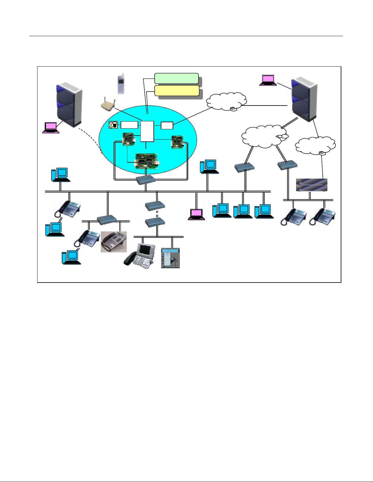
The illustration below shows a typical system layout.
UNIVERGE NEAX 2000 IPS
MATWorX
(Via RS232C)
FTP
Server
DtermIP
Switching
Hub
Client PC
PSIII
ZT
LC/DLC
IP-PAD
Switching Hub (100Mbps
In-skin VMS
In-skin Router
COT
MP
IPT
(H.323
Handler)
Router
H.323 GK
MATWorX
(Via LAN)
PSTN
Router
OAI
Server
Dterm
Assistant
UNIVERGE NEAX 2000 IPS
MATWorX
(Via IP: CCIS)
CCIS over IP
Intranet
DHCP
Server
PSTN
Router
UNIVERGE
NEAX IPS
DtermIP
Remote PIM over IP
with Survivability
DMR
DtermIP
Client PC
Dterm
INASET
Dterm SP30
Station to Station Connection
For DtermIP to DtermIP connection (Peer to Peer connection), the voice data is transmitted and
received directly between DtermIPs on the LAN. For Dterm Legacy terminal connection, the IPPAD card and VCT card are required to transmit and receive the voice data. These cards are used
to control and convert the voice data. The MP card in either of the connections above manages the
control signals
.
CCIS Connection
DtermIP to DtermIP connection (Peer to Peer connection) via CCIS is available only when the
destination office is
provides only Point to Multipoint connection
UNIVERGE NEAX 2000 IPS or UNIVERGE NEAX 2400 IPX. The system
.
Maintenance
MATWorX IPS is used as the maintenance program for the UNIVERGE NEAX 2000 IPS. Direct
connection (RS-232C), Modem connection and LAN (TCP/IP) connections are available to connect
to the MAT (Maintenance Administration Terminal).
Page 1-12 UNIVERGE NEAX 2000 IPS Request for Proposal (RFP) Reference Guide
Issue 6
Page 19

Chapter 1 Introduction
Hybrid System of IP (peer-to-peer connection) and TDM Switching
The UNIVERGE NEAX 2000 IPS supports both pure IP switching (peer-to-peer connections) and Time
Division Switching (TDM). The pure IP switching is provided for communications between DtermIPs
and for CCIS/Remote PIM connections with another
DML/2400 IPX (CCIS over IP or Remote PIM over IP). On the other hand, the TDM switching is
provided for communications between legacy stations/trunks. Connections between DtermIP/CCIS or
Remote PIM over IP and legacy stations/trunks are made via IP PADs, which converts packet-based
voice data to TDM-based voice data, and vice versa.
UNIVERGE NEAX 2000 IPS/IPS DM/IPS
Built-in DRS (Device Registration Server) on MP
The UNIVERGE NEAX 2000 IPS incorporates DRS (Device Registration Server) on MP, which provides
a Log-in/Log-out management of DtermIP including Registration, Authentication. Also the built-in DRS
can be inter-worked with DHCP server to provide easy administration of IP address
.
Reduced Hardware with IP based Architecture
The DtermIPs accommodated in a LAN do not require a DLC card because they can be interfaced
directly with the LAN and connected on a peer-to-peer basis. When a DtermIP is connected with
station/trunk, which is accommodated in TSW, the speech path between LAN and TSW is made via IP
PAD under the call processing control of MP. The number of DtermIPs can be simply expanded by
adding the terminal itself, an IP Seat License and IP PADs if traffic volume is increased. With this
system architecture, the hardware such as DLC, PIM, Power Supply etc. is reduced and easy cost
effective move, add, change is realized.
Office Data Backup Enhancement
The office data of UNIVERGE NEAX 2000 IPS is stored in Flash ROM.
Various Installation Methods
To meet the specific needs of the customers’ environment, the UNIVERGE NEAX 2000 IPS provides the
following installation methods:
Floor Standing Installation
Wall-mounting Installation
IEC standard 19-inch Rack-mounting Installation
Unified Circuit Card Size
All the circuit cards for UNIVERGE NEAX 2000 IPS are designed in one size (PN-type), and installed in
the PIM. This maximizes the efficiency of slot utilization of the PIM.
High Density Line/Trunk Cards
Major line/trunk cards used in UNIVERGE NEAX 2000 IPS are provided with 8 circuits per card. This
allows the physical system size to be compact.
UNIVERGE NEAX 2000 IPS Request For Proposal (RFP) Reference Guide Page 1-13
Issue 6
Page 20

Chapter 1 Introduction
Universal Slot
One PIM provides 12 card slots for Line/Trunk (LT). Also, these card slots can be used for Application
Processor (AP) cards without complicated limitations. As this makes easy quotation and installation,
more number of AP cards can be mounted in one PIM.
DC/DC Power Supply for –48V
The PIM houses optional DC/DC Power Supply for the cards which require –48V power such as CSI
card used for interface of Cell Station (CS) of wireless system. Since this power supply is mounted in
the space under the AC/DC power, additional Power Module/card slots are not required.
Extended Application Processor (AP) Port Capacity
The UNIVERGE NEAX 2000 IPS provides a maximum of 256 AP ports and it is independent of the 512
physical ports for legacy Line/Trunk (LT), therefore, more AP cards can be used in the system such as
T1/E1 digital link, etc.
Dual MP System
The system complies with dual control system on Main Processor.
Note: Since the system employs Cold Standby processing in MP changeover, the calls in progress are
terminated as a result of the MP changeover. Also, during the MP changeover, the call originating/receiving and
service feature access are not effective. (It takes about 30 to 60 seconds to complete the MP cha ngeover.)
UNIVERGE NEAX IPS DM
The UNIVERGE NEAX IPS DM (Internet Protocol Server Distributed Model) is equipped with all
the features and functions of the UNIVERGE NEAX 2000 IPS, with a smaller space
requirement. It is a full-featured PBX that supports advanced networking, pure peer-to-peer IP
telephony connectivity and traditional TDM switching capabilities. Designed primarily for pure
converged IP networks, the UNIVERGE NEAX IPS DM can also accommodate a mixed (i.e.,
TDM and IP) converged IP network or standalone solution.
The UNIVERGE NEAX IPS DM supports up to 952 peer-to-peer IP stations and 56 TDM ports
in a single modular chassis. Up to two chassis can be stacked providing maximum capacity of
112 legacy TDM ports while still supporting as many as 888 peer-to-peer IP stations or more
depending on the amount of TDM stations used. It uses the same CPU, line/trunk cards,
application processor cards and software of the UNIVERGE NEAX 2000 IPS and comes
equipped for 19” rack mounting. It offers superior port density; each chassis only occupies two
Rack Units (2RU).
Page 1-14 UNIVERGE NEAX 2000 IPS Request for Proposal (RFP) Reference Guide
Issue 6
Page 21

Chapter 1 Introduction
UNIVERGE NEAX IPS DML
The UNIVERGE NEAX IPS DML (Internet Protocol Server Distributed Model Local) is a
UNIVERGE NEAX IPS DM that has been optimized for Small Office Stand Alone IP Solution
with from 10 to 100 IP telephones. The
the Main Processor. The SPN-CP31C is a cost down CPU to compete with Mitel 3100,
NBX25, and CISCO 2600 Series. This system targets users with up to 112 TDM station, 128
IP stations and can be used as an end point in a peer-to-peer CCIS network. The following
options that are built-in on the CP24 are not available with the CP31:
No built-in DAT.
Only one RS Port.
No built-in DK (external/relay key).
No MN Alarm Indication
UNIVERGE NEAX IPS DML uses the SPN-CP31C as
UNIVERGE NEAX IPS DMR
The UNIVERGE NEAX IPS DMR (Internet Protocol Server Distributed Model Remote) is an
UNIVERGE NEAX IPS DM that has been optimized for Remote PIM over IP applications. The
UNIVERGE NEAX IPS DMR uses the SPN-CP31C as the Main Processor. The SPN-CP31C
is a cost down CPU to compete with Mitel 3100, NBX25, and CISCO 2600 Series. This
system targets users who have up to 30 relatively small offices that accommodate 10-30
extensions at the Remote Site. The MP card at Remote Site has the same system data as
that at Main Site, because Remote Site automatically gets the data from Main Site at the time
of setup. In normal operation, Main Site automatically copies the system data to Remote Site
through the network once a day.
The following options that are built-in on the CP24 are not available with the CP31 in an
UNIVERGE NEAX IPS DMR:
No built-in DAT.
No built-in Modem
Only one RS Port.
No built-in DK (external/relay key).
No MN Alarm Indication
System Outline for Remote PIM
The MP card at Main Site controls system processing, and Remote Site follows the Main Site.
Remote Site can accommodate most terminals and trunks such as Dterm, Single-Line
telephone, DSS/BLF Console, DtermIP, COT, ISDN, etc. The Attendant Console, Dterm
Attendant position, and Add-on Module are not supported at the Remote Site.
Local Switch (TDSW) at Remote Site controls connections within the Remote Site if possible.
In the case of connections between Main-Remote and Remote-Remote, the voice path is
connected via Peer-to-Peer or IP-PAD.
If the communications between Main-Remote are interrupted, the Remote Site survives by itself
after a system reset.
UNIVERGE NEAX 2000 IPS Request For Proposal (RFP) Reference Guide Page 1-15
Issue 6
Page 22

Chapter 1 Introduction
Advantages of Remote PIM
The system regards the terminals accommodated in both Main Site and Remote Site as the
extensions in the same office. Therefore, the service transparency is superior to CCIS.
Remote PIM over IP has no limitation of distance between Main and Remote.
Remote Site has a switching function at local. This provides the effective configuration of C.O.
line. In addition, the Remote Site can accommodate AP cards. This is an advantage to
accommodate ISDN lines especially.
The Remote Site survives by itself even if the link between Main and Remote is disconnected.
Therefore, the impact to users at the Remote Site will be smaller if the link between Main and
Remote is disconnected.
This feature can reduce the bandwidth used on the WAN that is connected to CO lines at
Remote Site, rather than DtermIP at remote location or the Media Converter (MC)
accommodation.
Characteristics of the UNIVERGE NEAX IPS DM/IPS DML/IPS DMR
Compact and Small Size MODULAR CHASSIS
One MODULAR CHASSIS provides 8 card slots /56LT ports (8 virtual LT ports are available per
MODULAR CHASSIS in addition to 56LT ports).
2 MODULAR CHASSIS can be used per system for IPS DM/DML/IPS DMR
MP (Main Processor)
PN-CP24A/B/C for IPS DM, the same MP as the UNIVERGE NEAX2000 IPS.
PN-CP31C for IPS DML
Power Failure Transfer (PFT)
Power Failure Transfer (PFT) for the IPS DM is provided with PZ-4PFTA card. The PZ-8PFTB is not
available for the IPS DM.
Installation Methods
UNIVERGE NEAX IPS DM/IPS DML/IPS DMR can be installed on a desktop or into the 19-inch
The
rack. Wall Mount Installation is not available.
Remote PIM over IP with Survivability
UNIVERGE NEAX 2000 IPS can have a PIM installed at a remote site through an IP network. At
The
the main site, the
DM/IPS DMR
UNIVERGE NEAX IPS/IPS DM is installed and UNIVERGE NEAX 2000 IPS/IPS
or IPS Retro is installed at the remote site. The main site controls call processing and
service feature access for station users located at both the main and remote sites. When the Remote
PIM cannot be connected with main site due to the IP network and/or main PBX failure, the Remote
PIM initializes the system and re-starts operation by its own Main Processor (survival mode). In the
survival mode, almost all service features are provided to the station users accommodated in Remote
PIM. When the IP network/main PBX recovers, the Remote PIM can be restored to normal mode with
a system initialization by manual operation or automatically (Selectable by system data setting).
IPS DMR with CP31A/C MP
IPS PIM with CP24A/B/C or CP27A MP
IPS Retro with CP26 or CP28 MP
and PN-CP31A/C for IPS DMR
Page 1-16 UNIVERGE NEAX 2000 IPS Request for Proposal (RFP) Reference Guide
Issue 6
Page 23
Chapter 1 Introduction
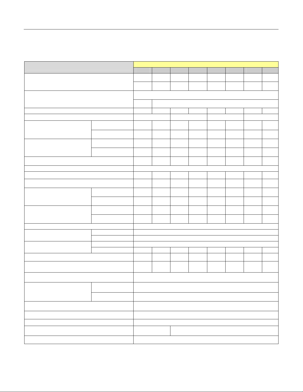
Stand Alone System Capacity
IPS System Capacity (Single MP System)
Item
(No. of Ports)
LT Card
(No. of Cards)
(No. of Ports)
AP Card
(No. of Cards)
Total Number of Lines (Single Line Tel. + Dterm) 64 128 192 256 320 384 448 512
IP PAD (No. of Channel) 64 128 192 256
Single Line Telephone
(Lines)
Standard 64 128 192 256 320 384 448 512
Long 48 96 144 192 240 288 336 384
PIM1 PIM2 PIM3 PIM4 PIM5 PIM6 PIM7 PIM8
64 128 192 256 320 384 448 512
12 24 36 48 60 72 84 96
12 24
Capacity Per PIM Note
Max. 256 ports per system
Dterm (Lines)
Dterm IP/Dterm IP INASET (PTP Connection) 952 888 824 760 696 632 568 504
Dterm PS 512
Cell Station (CS) / Zone Transceiver (ZT) 16 32 48 64 80 96 112 128
ISDN Station 16 32 48 64 80 96 112 128
Central Office Trunk (Lines)
Tie Line Trunk (Lines)
CCIS Trunk (Peer to Peer Connection) Max. 127
DTI/CCIS Digital Link
ISDN
IP Trunk 1 2 3 4 5 6 7 8
PFT Connections 8 16 24 32 40 48 56 64
3-Party Conference Max. 16 conference groups per system
Standard 64 128 192 256 320 384 448 512
Long 24 48 72 96 120 144 168 192
Loop Start 64 128 192 256 256 256 256 256
DID w/4DID 48 96 144 192 240 256 256 256
2W E&M 24 48 72 96 120 144 168 192
4W E&M 24 48 72 96 120 144 168 192
1.5M DTI: 10, CCIS: 8
2MI 8
1.5M/2M (PRT) 8
4BRT (card) 6 12 18 24 24 24 24 24
6-/10-Party Conference
32-Party Conference Max. 8 conference group per system
Built-in Router Max. 8 cards per PIM
DTMF Sender Max. 32 circuits per system
DTMF Receiver 16 32
Attendant Consoles 8
UNIVERGE NEAX 2000 IPS Request For Proposal (RFP) Reference Guide Page 1-17
Issue 6
6-Party Max. 4 conference groups per system
10-Party Max. 2 conference groups per system
Page 24

Chapter 1 Introduction
IPS System Capacity (Single MP System cont’d)
Item
Capacity Per PIM Note
PIM1 PIM2 PIM3 PIM4 PIM5 PIM6 PIM7 PIM8
Attendant Terminal (Dterm ATT Position) Max. 8 sets per system
SMDR Interface
PMS Interface
Max. 2 Interface ports (RS232)
Max 1 interface port (IP) per system
Max. 1 Interface port (RS232)
Max 1 interface port (IP) per system
ACD / MIS or OAI Interface Max. 1 interface port per system
Remote PIM over IP (Number of PIM for Remote
Sites)
Up to 30 (depending on network)
DID Dial Conversion 1000
Call Forwarding-Outside Set 496
Authorization. Code / Forced Account Code /
Remote Access to System(DISA)Code
3000
Message Reminder Set 1024
Name Display / Guest Name Display 512
Speed Calling-Station (Station Speed Dial) Set 10000
MP built-in SMDR Call Record 1024
Note: System Capacity is for Main site only. For Total System Capacity see IP Remote Network System
Capacity.
Page 1-18 UNIVERGE NEAX 2000 IPS Request for Proposal (RFP) Reference Guide
Issue 6
Page 25
Chapter 1 Introduction
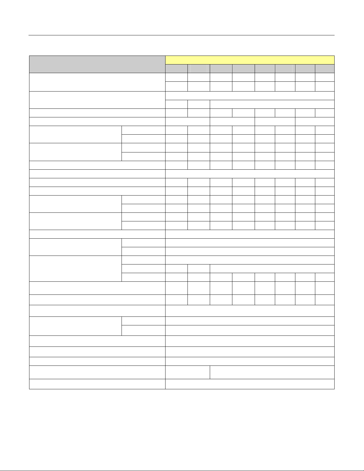
IPS System Capacity (Dual MP System)
Item
(No. of Ports)
LT Card
(No. of Cards)
(No. of Ports)
AP Card
(No. of Cards)
PIM1 PIM2 PIM3 PIM4 PIM5 PIM6 PIM7 PIM8
64 128 192 256 320 384 448 512
11 23 35 47 59 71 83 95
11 23 24
Capacity Per PIM Note
Max. 256 ports per system
Total Number of Lines (Single Line Tel. + Dterm) 64 128 192 256 320 384 448 512
IP PAD (No. of Channel) 64 128 192 256
Single Line Telephone (Lines)
Dterm (Lines)
Standard 64 128 192 256 320 384 448 512
Long 44 92 140 188 236 284 332 380
Standard 64 128 192 256 320 384 448 512
Long 22 46 70 94 118 142 166 190
Dterm IP/Dterm IP INASET (PTP Connection) 952 888 824 760 696 632 568 504
Dterm PS 512
Cell Station (CS) / Zone Transceiver (ZT)
ISDN Station
Loop Start
Central Office Trunk (Lines)
Tie Line Trunk (Lines)
DID w/4DID 44 92 140 188 236 256 256 256
2W E&M 22 46 70 94 118 142 166 190
4W E&M 22 46 70 94 118 142 166 190
16 32 48 64 80 96 112 128
16 32 48 64 80 96 112 128
64 128 192 256 256 256 256 256
CCIS Trunk (Peer to Peer Connection) Max. 127
DTI/CCIS Digital Link
1.5M-AMI DTI: 10, CCIS: 8
2M-AMI 8
1.5M/2M (PRT) 8
ISDN
2BRT (card) 11 23 24
4BRT (card) 6 12 18 24 24 24 24 24
IP Trunk
1 2 3 4 5 6 7 8
PFT Connections
8 16 24 32 40 48 56 64
3-Party Conference Max. 16 conference groups per system
6-Party Max. 4 conference groups per system
6-/10-Party Conference
10-Party Max. 2 conference groups per system
32-Party Conference Max. 8 conference group per system
Built-in Router Max. 8 cards per PIM
DTMF Sender Max. 32 circuits per system
DTMF Receiver 16 32
Attendant Consoles 8
UNIVERGE NEAX 2000 IPS Request For Proposal (RFP) Reference Guide Page 1-19
Issue 6
Page 26
Chapter 1 Introduction
IPS System Capacity (Dual MP System, Cont’d)
Item
Capacity Per PIM Note
PIM1 PIM2 PIM3 PIM4 PIM5 PIM6 PIM7 PIM8
Attendant Terminal (Dterm ATT Position) Max. 8 sets per system
SMDR Interface
PMS Interface
Max. 2 Interface ports (RS232)
Max 1 interface port (IP) per system
Max. 1 Interface port (RS232)
Max 1 interface port (IP) per system
ACD / MIS or OAI Interface Max. 1 interface port per system
Remote PIM over IP (Number of PIM for Remote
Sites)
Up to 30 (depending on network)
DID Dial Conversion 1000
Call Forwarding-Outside Set 496
Authorization. Code / Forced Account Code /
Remote Access to System(DISA)Code
3000
Message Reminder Set 1024
Name Display / Guest Name Display 512
Speed Calling-Station (Station Speed Dial) Set 10000
MP built-in SMDR Call Record 1024
Note: Capacity is for Main site only. For Total System Capacity see IP Remote Network System Capacity.
Page 1-20 UNIVERGE NEAX 2000 IPS Request for Proposal (RFP) Reference Guide
Issue 6
Page 27

Chapter 1 Introduction
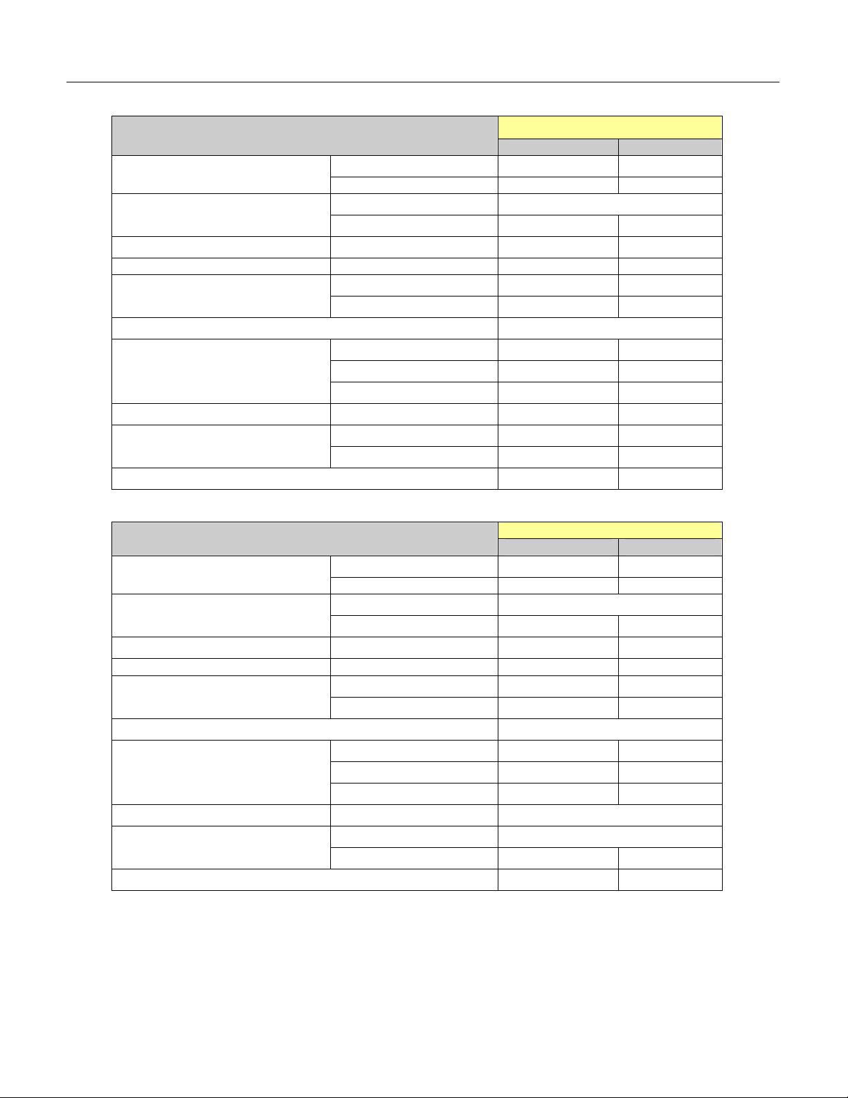
IPS DM/IPS DML System Capacity
Number of PHYSICAL MODULAR CHASSIS
Capacity Per MC
1 2
LT card Note 1
No. of ports 56 112
No. of cards 7 14
AP card
No. of ports Max. 256 ports per system
No. of cards 7 14
Total number of lines (Single Line Telephone + Dterm) 56 112
IP-PAD No. of channel 32 64
Single Line Telephone
(Lines)
Dterm(Lines)
8LC 56 112
Long Line Not Available
Standard 56 112
Long Line 8 16
DtermIP/DtermIP/INASET/SP30(PTPConnection)Note 3 952 888
ISDN Station 10 20
Loop Start 56 112
Central Office Trunk (Lines)
DID w/4DID 28 56
2W/4W E&M 14 28
CCIS Trunk (Peer to Peer Connection) Max. 127
DTI/CCIS Digital Link
Note 2
ISDN
1.5M 7 DTI: 10, CCIS: 8
2M 7 8
1.5M/2M(PRT) 7 8
4BRT (card) 5 10
IP Trunk 1 2
PFT Connections 4 8
3-Party Conference
6-/10-Party Conference
6-Party Max. 4 conference groups per system
10-Party Max. 2 conference groups per system
32-Party Conference 5
Max. 16 conference groups per
system
Max. 8 conference
groups per system
UNIVERGE NEAX 2000 IPS Request For Proposal (RFP) Reference Guide Page 1-21
Issue 6
Page 28

Chapter 1 Introduction
IPS DM/IPS DML System Capacity Cont
Number of PHYSICAL MODULAR CHASSIS
Built-in Router Max. 1 card per Site
DTMF Sender Max. 32 circuits per system
DTMF Receiver 16 32
SN716 Desk Console 8
Attendant Terminal (Dterm ATT Position) Max. 8 per system
SMDR Interface
PMS Interface
Max 1 interface port (IP) per system
Max 1 interface port (IP) per system
ACD / MIS or OAI Interface Max. 1 Interface port per system
Remote PIM over IP (Number of PIM for Remote
Sites) Note 3
Up to 30 (depending on network)
DID Dial Conversion 1000
Call Forwarding-Outside Set 496
Authorization Code / Forced Account Code / Remote
Access to System(DISA) Code
Message Reminder Set 1024
Name Display / Guest Name Display 512
Speed Calling-Station (Station Speed Dial) Set 10000
MP built-in SMDR Call Record Note 3 1024
Capacity Per MC
1 2
Max. 2 Interface ports (RS232)
Max. 1 Interface port (RS232)
3000
Note 1: Each Modular Chassis has 8 Virtual LT Ports that can only be used to expand the PAD
channels from 24 to 32 using the 8IPLA w/24IPLA.
Note 2:
The total number of trunk line and DTI channel shall be 256 or less. (Each trunk line and DTI
channels are required to assign the “Trunk Number” by system data programming and
maximum number of system parameter for “Trunk Number” is 256.)
Note 3: IPS DML only supports a maximum of 128 IP stations; IPS DML
does not support built-in
SMDR. The IPS DML is a Stand Alone Only solution; Remote PIM’s off the IPS DML are not
supported.
Page 1-22 UNIVERGE NEAX 2000 IPS Request for Proposal (RFP) Reference Guide
Issue 6
Page 29

Chapter 1 Introduction
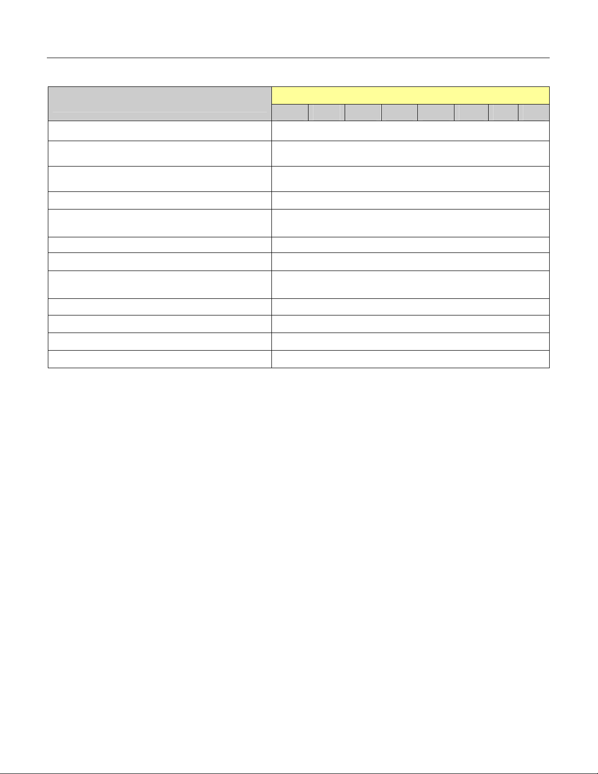
IP Remote Network Capacity
Total System Capacity (Main plus Remote)
Item Capacity
LT Ports 1020
AP Ports 256
Analog Single Line Tel. + Dterm 980
IP PAD (No. of Channel) 256
Dterm IP/Dterm IP INASET (PTP Connection) 952
Dterm PS 512
Cell Station (CS) / Zone Transceiver (ZT)
ISDN Station
Central Office Trunk (Lines) 256
Tie Line Trunk (Lines) 2W/4W E&M 192
CCIS Trunk (Peer to Peer Connection) 127
DTI/CCIS Digital Link 1.5M/2M DTI: 10/CCIS: 8 Links
ISDN
IP Trunk 8
PFT Connections 64
3-Party Conference Max. 16 conference groups
6-/10-Party Conference
32-Party Conference Max. 8 conference groups
Built-in Router 1 per Site
DTMF Sender/Receiver Max. 32 circuits
Attendant Consoles 8
Attendant Terminal (Dterm ATT Position) Max. 8 sets
SMDR Interface
PMS Interface
ACD / MIS or OAI Interface Max. 1 interface port
Remote PIM over IP Note Up to 30 (depending on network)
DID Dial Conversion 1000
Call Forwarding-Outside Set 496
Authorization Code / Forced Account Code / Remote
Access to System(DISA)Code
Message Reminder Set 1024
Name Display / Guest Name Display 512
Speed Calling-Station (Station Speed Dial) Set 10000
MP built-in SMDR Call Record 1024
1.5M/2M (PRT) 8
4BRT (card) 24
6-Party Max. 4 conference groups
10-Party Max. 2 conference groups
Max. 2 Interface ports (RS232)
Max 1 interface port (IP) per system
Max. 1 Interface port (RS232)
Max 1 interface port (IP) per system
Note: Remote PIM networks using the IPS DML as the main are not supported.
128
128
3000
UNIVERGE NEAX 2000 IPS Request For Proposal (RFP) Reference Guide Page 1-23
Issue 6
Page 30
Chapter 1 Introduction
IPS DMR Capacity
Number of PHYSICAL MODULAR CHASSIS
Capacity Per MC
1 2
LT card Note 1
AP card
No. of ports 56 112
No. of cards 7 14
No. of ports Max. 256 ports per network
No. of cards 7 14
IP-PAD No. of channel 32 64
Single Line Telephone (Lines) 8LC 56 112
Dterm(Lines)
Standard 56 112
Long Line 8 16
DtermIP/DtermIP/INASET(Peer to Peer Connection) Note 2 128
Loop Start 56 112
Central Office Trunk (Lines)
DID w/4DID 28 56
2W/4W E&M 14 28
DTI 1.5M 7 10
ISDN
1.5M(PRT) 7 8
4BRT (card) 5 10
PFT Connections 4 8
IPS PIMMJ (As Remote PIM) Capacity
Number of PHYSICAL PIMS
LT card
AP card
No. of ports 64 128
No. of cards 8 16
No. of ports Max. 256 ports per network
Capacity Per PIM
1 2
No. of cards 12 24
IP-PAD No. of channel 32 64
Single Line Telephone (Lines) 8LC 64 128
Dterm(Lines)
Standard 64 128
Long Line 24 48
DtermIP/DtermIP/INASET(Peer to Peer Connection) Note 2 128
Loop Start 64 128
Central Office Trunk (Lines)
DID w/4DID 48 96
2W/4W E&M 24 48
DTI 1.5M 10
ISDN
1.5M(PRT) 8
4BRT (card) 6 12
PFT Connections 8 16
Note 1: Each Modular Chassis has 24 Virtual LT Ports that can only be used to expand the PAD
channels from 8 to 32 using the 8IPLA w/24IPLA.
Note 2:
Remote PIM’s Support up to 2 Virtual PIM’s for assignment of DtermIP/DtermIP/INASET only.
Page 1-24 UNIVERGE NEAX 2000 IPS Request for Proposal (RFP) Reference Guide
Issue 6
Page 31

Chapter 2 System Architecture
The UNIVERGE NEAX 2000 IPS family consists of the IPS, IPS DM, IPS DML and IPS DMR.
These
dynamic advancements in hardware and software to satisfy the most stringent system
requirements. NEC's modular design, sensible migration, comprehensive network solutions,
and the ability to customize functionality to match specific business applications are just a few
of the NEC benchmarks that the new IPS builds upon.
UNIVERGE NEAX 2000 IPS users have access to hundreds of service features that enhance
productivity, reduce operating costs, and improve communications efficiently. The innovative
modular hardware and software design allows efficient, effective growth within each module
from its minimum to its maximum configuration. This is achieved by a unique building block
architecture allowing growth without the loss of existing hardware or software.
Voice and Data Switching
UNIVERGE NEAX 2000 Internet Protocol Servers fuse existing NEC technologies with
The UNIVERGE NEAX 2000 IPS systems support advanced applications such as Tandem Networking,
Centralized Attendant Service, Direct Digital Interface and other voice features. The system's nonblocking architecture and distributed processor control hierarchy are designed to support the traffic and
control the load generated by voice and data switching. Station users may perform simultaneous voice
and data transmission at speeds up to 19.2Kbps over universal 1-pair wiring without the use of
modems. Proprietary Digital Instruments (Dterm) may be provided to increase system flexibility and
eliminate the need for conventional multiple line stations with their associated control equipment and
cable plant requirements.
Hardware Architecture
The UNIVERGE NEAX 2000 IPS systems employ the latest advancements in Large Scale
Integration (LSI) circuits and component manufacturing techniques to create a highly reliable
and serviceable communications system. The IPS has changed from NEC's traditional PROM
based CPUs to a Flash ROM based for system software and RAM for data programming. The
UNIVERGE NEAX 2000 IPS architecture consists of three major functional components:
Distributed Controller, Digital Switching Network, and Port Interface.
1. Distributed Controller - The Distributed Controller is composed of distributed
multiprocessing units, generic memory, database instructions, system interface, and
interface ports for system maintenance and administration.
2. Digital Switching Network - The Digital Switching Network consists of a non-blocking
digital time division switch, allowing all ports to be used simultaneously.
3. Port Interface - The Port Interface provides access to the public and private network for
various types of terminal devices, including digital and analog telephones, data terminals,
computers and subsystems such as Voice Mail Systems, Data Switch Networks, and
related communication and information services.
UNIVERGE NEAX 2000 IPS Request For Proposal (RFP) Reference Guide Page 2-1
Issue 6
Page 32

Chapter 2 System Architecture
Hardware Design
The UNIVERGE NEAX 2000 IPS hardware is designed to provide the best of the following:
Flexibility
Capacity
Reliability
Optimum use of space
Minimal environmental requirements
Ease of installation and maintenance
A unique modular design is employed throughout the UNIVERGE NEAX 2000 IPS line of products. As
additional equipment modules are required, they are stacked on top of each other, rather than mounting
the equipment in conventional frames or cabinets. This innovative method reduces installation time,
avoids the use of bulky frames and provides for manageable future expansion, virtually eliminating the
possibility of outgrowing your
UNIVERGE NEAX 2000 IPS.
Fusion of RAM and ROM Programs
The UNIVERGE NEAX 2000 IPS incorporates the flexibility of Random Access Memory (RAM) for Office
Data Memory and Flash ROM that contains the operating system. This fusion of divergent memory
technologies results in high performance 32-bit processing reliability in system operation as well as fast
recovery time in case of system power loss. This unique configuration provides improved efficiency for
updates to the generic program by floppy disk, and simplifies upgrades for system features and
capabilities throughout its life cycle
.
Main Processor (MP) with Integrated Functionality
The UNIVERGE NEAX 2000 IPS Main Processor (MP) is a heart of pure IP connections and TDM-
based connections. The MP employs a high-speed CPU, which is equivalent with Pentium. With this
processing power and System On Chip (SOC) technology, the MP integrates Device Registration
Server (DRS), AP01 (OAI) functions*, which are provided by an additional card in the previous IVS
2
.
Also, by means of today's advanced LSI technology, the MP card size is minimized and On-board
Ethernet Interface Card is mounted on MP without using an additional slot space in PIM. This interface
card is linked with LAN for call control processing of DtermIP and inter-work with MATWorX and OAI
server. (*RS-232C interface, Authorization Code service and FLF facility are deleted.)
Application Processors
The processing architecture of the UNIVERGE NEAX 2000 IPS allows the system to be configured with
Application Processors that provide processing capacity for a specific application or multiple
applications. These EPROM-based processors support applications such as:
ACD Processor for call center applications
SMDR for call accounting
Hotel Processor for Hospitality applications
Message Center Interface (MCI)
Open Applications Interface (OAI), which connects to external computing devices to support a
wide range of host computer-supported features
These application processors provide the power and flexibility to meet specific users’ applications and
traffic needs.
.
Page 2- 2 UNIVERGE NEAX 2000 IPS Request For Proposal (RFP) Reference Guide
Issue 6
Page 33

Chapter 2 System Architecture
Integration
In addition to the application processors manufactured by NEC, the UNIVERGE NEAX 2000 IPS
systems also deliver an open architecture for integration with other manufacturers. Interface
processors and specifications for communicating with computing devices support this integration.
These computing devices enable such service features as network and facilities management, call
center applications, call accounting, property management, voice mail, maintenance access terminals,
and management information systems for ACD reports and monitoring.
Unified Circuit Card
All the circuit cards for UNIVERGE NEAX 2000 IPS are designed in one size (PN-type), and installed in
the PIM. This maximizes the efficiency of slot utilization of the PIM.
High Density Line/Trunk Cards
Major line/trunk cards used in UNIVERGE NEAX 2000 IPS are provided with 8 circuits per card. This
allows the physical system size to be compact.
Universal Slot
One PIM provides 12 card slots for Line/Trunk (LT). Also, these card slots can be used for Application
Processor (AP) cards without complicated limitation. As this makes easy quotation and installation,
more number of AP cards can be mounted in one PIM.
DC/DC Power Supply for –48V
The PIM houses an optional DC/DC Power Supply for the cards which require –48V power such as the
CSI card used for interface of Cell Station (CS) of a wireless system. Since this power supply is
mounted in the space under the AC/DC power, additional Power Module/card slots are not required.
SN716 Attendant Console
The SN716 Attendant Console connection is available through one twisted-pair cable when using an
AC adapter. When using the PN-PW00, one twisted-pair cable is required for voice/data and one pair
is required for power from the PW00 to the Console.
Analog/Digital Telephones
The analog/digital telephone connection is available through one twisted-pair cable.
IP Telephones
The IP telephones can communicate with other IP telephones over the LAN, on a peer-to-peer
connection basis. The Main Processor (MP) provides call control with an Ethernet adapter card. Voice
packets are transmitted between IP telephones over the LAN (not through Time Division Switch). Voice
compression of G.729a (8 kbps) and G.723.1 (5.3 kbps/6.3 kbps) is available for these connections.
The IP telephones can communicate with legacy stations and trunks (including H.323 trunks) via an IPPAD that converts voice packet data to PCM signals. Call control signals are transmitted to the MP over
the LAN, while voice packets are transmitted via the IP-PAD. The number of IP-PADs depends on the
traffic volume of connections between the IP Enabled Dterm and legacy stations and trunks.
UNIVERGE NEAX 2000 IPS Request For Proposal (RFP) Reference Guide Page 2-3
Issue 6
Page 34

Chapter 2 System Architecture
t
t
UNIVERGE NEAX 2000 IPS System Configuration
The UNIVERGE NEAX 2000 IPS consists of single or multiple Port Interface Modules (PIM)
depending on the system configuration, and there are two types of PIM’s; “Physical” PIM and
“Virtual” PIM. The Physical PIM is “hardware” PIM which is used to accommodate an MP,
FPs, IP PADs, legacy LT cards, AP cards, and power supply units. One Physical PIM provides
up to 64 LT ports and up to 8 Physical PIM’s can be accommodated in a Stand Alone system.
A Virtual PIM is a “software” PIM and provides up to 64 ports per PIM for use by system
programming as DtermIP telephones, Wireless PS stations or Peer to Peer (PTP) CCIS trunks.
The system consists of up to 16 PIM’s, by the combination of Physical PIM’s and Virtual PIM’s,
thus providing 1020 ports. When the use of Virtual PIM’s exceeds 8 then the number Physical
PIM’s is reduced by one for each additional Virtual PIM required.
The illustration below shows examples of 1020-port configuration by the combination of TDM
LT ports, Dterm IP telephones, Wireless PS stations and Peer to Peer (PTP) CCIS trunks.
Example 1 Example 2
PIM #3
PIM #2
PIM #1 PIM #5
PIM #0 PIM #4
448 LT ports +
64 IP-PADs
PIM #7
PIM #6
PIM #11
PIM #10
PIM #9 PIM #13
PIM #8 PIM #12
252 D
Wireless + 128
PTP CCIS
PIM #15
PIM #14
erm
IP + 128
PIM
Physical PIM
PIM #3
PIM #2
PIM #1 PIM #5
PIM #0 PIM #4
192 LT ports +
64 IP-PADs
PIM #7
PIM #6
PIM
Virtual PIM
PIM #11
PIM #10
PIM #9 PIM #13
PIM #8 PIM #12
508 D
Wireless + 128
PTP CCIS
PIM #15
PIM #14
erm
IP + 128
Page 2- 4 UNIVERGE NEAX 2000 IPS Request For Proposal (RFP) Reference Guide
Issue 6
Page 35

Chapter 2 System Architecture
Module and Installation Hardware
The UNIVERGE NEAX 2000 IPS is comprised of up to 8 Port Interface Modules (PIM’s). For installing
the PIM’s in various installation methods, additional installation hardware is required.
Modules
1.) Port Interface Module (PIM)
A PIM provides 13 card slots for common control, Line/Trunk (LT), and Application Processor (AP)
cards. It also houses an AC/DC Power Supply, DC/DC Power Supply (for -48V), and batteries for
protection from short-term (about 30 min.) power interruption
.
Four champ connectors for Line/Trunk (LTC 0 to 3) are located at the lower front side of the PIM.
A PIM provides a maximum of 12 card slots for Line/Trunk (LT) and Application Processor (AP) cards.
At maximum configuration, the system is comprised of 8 PIM’s.
There are two types of PIM (PIMMJ and PIMMK) depending on the system type as follows.
Type of PIM Single MP System Dual MP System
PIM MJ Used for PIM 0-7 Used for PIM 1-7
PIM MK Not used Used for PIM 0
PIM MJ (PIM3) PIM MJ (PIM7) PIM MJ (PIM3) PIM MJ (PIM7)
PIM MJ (PIM2) PIM MJ (PIM6) PIM MJ (PIM2) PIM MJ (PIM6)
PIM MJ (PIM1) PIM MJ (PIM5) PIM MJ (PIM1) PIM MJ (PIM5)
PIM MJ (PIM0) PIM MJ (PIM4)
(Single MP System)
Unit Configuration
2.) Battery Module (BATTMH)
The BATTM is an optional module for installing optional long-term (about 3 hours) backup batteries.
The BATTM is designed to accommodate batteries covering up to a 4-PIM system (2 BATTMs support
maximum system configuration).
The BATTM is available for Floor Standing Installation or 19 inch Rack-mounting. (When the system is
Wall-mounted, the BATTM cannot be installed with the PIM.)
Modules
Abbrev Description Remarks
PIMMJ SN1729 PIMMJ Single MP System: PIM 0 - PIM 7
PIMMK SN1730 PIMMK Single MP System: Not used
BATTM SN1731 BATTMH 1 per STACK, Max.2 per system
PIM MK (PIM0)
PIM MJ (PIM4)
(Dual MP System)
Dual MP System: PIM 1 – PIM 7
Dual MP System: PIM 0
UNIVERGE NEAX 2000 IPS Request For Proposal (RFP) Reference Guide Page 2-5
Issue 6
Page 36

Chapter 2 System Architecture
Installation Hardware
Base/Top Assembly
The Base/Top Assembly includes a Base Unit and a Top Cover for the PIM. One Base/Top Assembly is
required for each PIM stack. The Base Unit also serves as the AC power distribution panel for up to a
four PIM configuration.
Hanger Assembly
The Hanger Assembly is used for Wall-mounting Installation. One set of Hanger Assembly is required
for each PIM.
19 inch Bracket
The 19-inch Bracket is a set of hardware used for 19-inch Rack-mounting Installation. The 19-INCH
RACK BRACKET (A) is installed on both sides of the PIM. One set of 19 inch Bracket (A) is required
for each PIM. The 19-INCH RACK BRACKET (B) is installed at the BASE of stack. One 19-INCH
BRACKET (B) is required for each stack.
If the system is 2 PIM or more configurations with 19-INCH BRACKET (B), one set of 19-INCH
BRACKET (A) is also required for the topmost PIM.
Optional Brackets
The Mounting Bracket is used for Floor Standing Installation. Without Mounting Bracket, 1.1G
shockproof is provided for 1 to 3-module stack and 0.5G shockproof is provided for 4 or more module
stack. To enhance the shockproof capability to 1.1G, one set of Mounting Bracket is required for each 4
or more module stack and attached to the topmost PIM.
The I/F Bracket is used for Floor Standing Installation to join the neighboring topmost PIM in 6 PIM or
more configurations. One set of I/F Bracket is required for multiple stacks.
The Base Tray Assembly is used for Floor Standing Installation for stationary equipment (UL complied).
One set of Base Tray Assembly is required for each stack.
Installation Hardware
Abbrev Description Quantity
Top Cover TOP COVER ASSEM 1/STACK (BASE ASSEM is local supply)
Base/Top ASSEM SN1545 BASERE 1/STACK
Hanger Assem HANGER ASSEM (UL) 1/PIM (Wall-mounting Installation)
19 INCH RACK BRACKET (A) 1/PIM (19 inch Rack-mounting Installation) 19 inch Bracket
19 INCH RACK BRACKET (B) 1/STACK (19 inch Rack-mounting Installation)
Mounting Bracket MOUNTING BRACKET OPTION (1/STACK)
I/F Bracket I/F BRACKET ASSEM OPTION (1/SYSTEM)
Base Tray BASE TRAY ASSEM OPTION (1/STACK)
Page 2- 6 UNIVERGE NEAX 2000 IPS Request For Proposal (RFP) Reference Guide
Issue 6
Page 37

Chapter 2 System Architecture
UNIVERGE NEAX 2000 IPS SYSTEM POWER SUPPLY
AC/DC Power Supply
The AC/DC Power Card is mounted in the left side of each PIM. The AC/DC Power card provides
power to all circuit cards, which reside in the PIM. AC power requirements are as follows:
Input Voltage: 90 to 132 Vrms or 180 to 264 Vrms (selectable by switch) 50/60 Hz
AC/DC Power Card
Name Code Qty Remarks
PZ-PW121 1 per PIM AC/DC Power Supply Input:100 V/200 V
Output:+5 V,-27 V,+90V, CR
DC/DC Power Unit
The DC/DC Power Unit is mounted under the AC/DC Power Card and generates -48 V power for the
circuit cards that need such power
Name Code Qty Remarks
PZ-PW122 1 per PIM DC/DC Power Supply, Input: -27 V, Output: -48 V
.
DC/DC (-48V) Power Card
Battery Backup
Internal Short-term option
For customers requiring battery backup, short-term and/or long-term options are available. Two 3.4AH
batteries are required per PIM, and installed inside of each PIM. Backup time is approx. 30 minutes
when PHS (Wireless PS) is not accommodated and approx. 10 minutes when PHS (Wireless PS) is
accommodated in the system.
Internal Battery Option
Name Code Qty Remarks
PWR CA-A 1 per (2) PIM’s DC Power Cable (-27v input)
BATT CA INT 1 per PIM Internal Battery Cable
External Long-term option
Two 24AH batteries are required per each 2 PIM’s, and installed inside of Battery Module in a stack
basis. Backup time is approx. 3 hours when PHS (Wireless PS) is not accommodated and approx. 2
hours when PHS (Wireless PS) is accommodated in the system. The batteries are varied depending
on the requested backup time. The battery shall be locally provided
External Battery Option
Name Code Qty Remarks
PWR CA-A (No. of PIM) –1= up to 4PIM
DC Power Cable (-27v input)
(No. of PIM) –2= 5 to 8PIM
BATT CA EXT 1/Stack External Battery Cable
.
UNIVERGE NEAX 2000 IPS Request For Proposal (RFP) Reference Guide Page 2-7
Issue 6
Page 38

Chapter 2 System Architecture
Cabling
The internal and external cabling for the UNIVERGE NEAX 2000 IPS is as follows:
Internal Cabling
BUS Cable
The BUS Cable provides a connection between PIM’s for I/O Bus, PCM Bus, and Alarm Bus extension
in a multiple-PIM configuration.
Bus Cable
Name Code Qty Remarks
48-TW-0.7 CONN CA (No. of PIM)-1 0.7 m (2.3ft.)
Power Control Cable
The Power Control Cable provides a connection between the MP and the AC/DC Power Supply for
controlling battery backup function and MJ/MN alarm indication.
Power Control Cable
Name Code Qty Remarks
PWR CNT CA-D 1/PIM Power control cable (for PIMI-PIM7):
BWB - PZ-PW121/122 (Included in
PIM)
PWR CNT CA-E 1/PIM Power control cable (for PIM0)
BWB - PZ-PW121/122 (Included in
Base and PIM for Dual System)
DC Power Cable
The DC Power Cable provides a connection between the AC/DC Power Supplies for extending the 27
VDC input in a multiple-PIM configuration, when battery backup option is required
Power Cable (Internal Battery Option)
Name Code Qty Remarks
PWR CA-A 1/2 PIM DC Power Cable (-27v input)
BATT CA INT 1/PIM Internal Battery Cable
Power Cable (External Battery Option)
Name Code Qty Remarks
PWR CA-A (No. of PIM) –1= up to 4PIM
DC Power Cable (-27v input)
(No. of PIM) –2= 5 to 8PIM
BATT CA EXT 1/Stack External Battery Cable
AC Cord
The AC cord provides a connection between the AC/DC Power Card and Base Unit.
AC Cord
Name Code Qty Remarks
AC CORD-B-U 1/PIM AC power cable (Included in PIM)
AC CORD-D-U 1/BASE AC power cable for BASE (Included in BASE)
.
Page 2- 8 UNIVERGE NEAX 2000 IPS Request For Proposal (RFP) Reference Guide
Issue 6
Page 39

Chapter 2 System Architecture
External Cabling
IP Connection
MP with PZ-M606-A and IP PAD
Name Code Qty Remarks
IP TRK BUS CA 1/VCT
IP TRK BUS Cable 0.1m (0.33ft)
(Included in SPN-16VCTA IP PAD)
IP Trunk (H.323, CCIS over IP w/IVS2)
Name Code Qty Remarks
IP TRK BUS Cable 0.1m (0.33ft)
IP TRK BUS CA 1/VCT
(Included in SPN-4VCTI-A, or
SPN-4VCTI-B.)
Maintenance Administration Terminal (MAT) (RS-232C)
Direct Connection
MAT Cable (Direct)
Name Code Qty Remarks
MAT CA-T 1/MAT RS-232C cable, 2m (6.6ft.)
MAT CA-P 1/MAT RS-232C cable, 4m (13.1ft.)
Remote connection
Remote connection is available via an internal modem in the MP or an external modem.
MAT Cable for external modem
Name Code Qty Remarks
RS NORM-4S CA-A 1/MAT RS-232C cable, 4m (13.1ft.)
UNIVERGE NEAX 2000 IPS Request For Proposal (RFP) Reference Guide Page 2-9
Issue 6
Page 40

Chapter 2 System Architecture
Built-in SMDR/MCI on MP
The MP card provides RS-232C interface ports for SMDR/MCI connection.
No. 0/1 Port: Async. : 1200/2400/4800/9600/19200 bps
Connection to SMDR is made on a port basis by a front cable
.
Cable for Built-in SMDR/MCI on MP
Name Code Qty Remarks
RS RVS-4S CA-C 1/SMDR
RS NORM-4S CA-A 1/SMDR
RS-232C cable, 4m (13.1ft.)
MP-DTE
RS-232C cable, 4m (13.1ft.)
MP-DCE (MODEM)
SMDR/PMS/Hotel Printer/MCI (with AP00B MRC-C)
The PN-AP00-B card provides 4 RS-232C interface ports for SMDR, PMS, CIS Printer, Hotel Printer,
MCI and Centralized SMDR. Connection to SMDR, PMS or Printer is made on a port basis by a front
cable.
Cable for AP00
Name Code Qty Remarks
RS RVS-4S CA-C 1/SMDR or
PMS
RS NORM-4S CA-A 1/SMDR or
PMS
RS PRT-15S CA-A 1/Printer RS-232C cable, 15m (49.2ft.)
RS-232C cable, 4m (13.1ft.)
PN-AP00 - DTE
RS-232C cable, 4m (13.1ft.)
PN-AP00 - DCE (MODEM)
PN-AP00 - Printer
External Alarm Display
The UNIVERGE NEAX 2000 IPS can provide an optional external alarm display unit (ALM DSPP) to
indicate Power-ON/OFF, Major Alarm, and Minor Alarm status
.
External Alarm Display Panel
Name Code Qty Remarks
ALM DSPP 1/System External Alarm Display Panel
Digital Trunk Interface (DTI)
Primary Rate Interface (PRI)
CCIS Trunk Interface (CCT)
The DTI/PRI/CCT connection is available through twisted-pair cable via the MDF
Page 2- 10 UNIVERGE NEAX 2000 IPS Request For Proposal (RFP) Reference Guide
.
Issue 6
Page 41

Chapter 2 System Architecture
(
)
UNIVERGE NEAX IPS DM/IPS DML/IPS DMR System Configuration
IPS DM/IPS DML Modular Chassis (MC)
The UNIVERGE NEAX IPS DM
configuration. The
UNIVERGE NEAX IPS DML
on the system configuration. The MODULAR CHASSIS provides 56 LT ports in hardware slots and
provides 64 ports in software port allocation (56 LT ports and 8 virtual ports). There are 2 types of
MODULAR CHASSIS; "Physical MODULAR CHASSIS" and "Virtual MODULAR CHASSIS ". The
Physical MODULAR CHASSIS is a “hardware MODULAR CHASSIS” and is used to accommodate an
MP, IP PADs, legacy LT/AP cards, and power supply units. The Virtual MODULAR CHASSIS is a
“software MODULAR CHASSIS” used to accommodate IP stations and Peer-to-Peer CCIS Trunks by
system data programming. The port capacity of the Virtual MODULAR CHASSIS is varied depending
on the number of Physical MODULAR CHASSIS.
One MODULAR CHASSIS provides 8 card slots including one card slot for Main Processor (MP) and
other 7 slots for Line Trunk (LT)/Application Processor (AP) cards; 56 LT ports and 8 virtual LT ports;
AC, LTC, BUS cable connectors and power switch which are located at the rear side of MODULAR
CHASSIS. The following illustration shows MODULAR CHASSIS hardware configurations, software
port allocation, face layout and rear view of MODULAR CHASSIS for IPS DM/IPS DML.
1 MODULAR CHASSIS
MC-0
MODULAR CHASSIS Software Port Allocation
consists of one to three MODULAR CHASSIS depending on the system
consists of one or two MODULAR CHASSIS depending
IPS DM MODULAR CHASSIS Hardware Configuration
2 MODULAR CHASSIS
Virtual
MODULAR
CHASSIS
(952 IP Ports)
Virtual
MODULAR
CHASSIS
888 IP Ports
56
LT ports
8 Virtual
LT ports
MC-1
MC-0
56
LT ports
56
LT ports
8 Virtual
LT ports
8Virtual
LT ports
256 AP Ports per System
UNIVERGE NEAX 2000 IPS Request For Proposal (RFP) Reference Guide Page 2-11
Issue 6
Page 42

Chapter 2 System Architecture
IPS DMR Modular Chassis (MC)
There are 2 types of MODULAR CHASSIS; "Physical MODULAR CHASSIS" and "Virtual MODULAR
CHASSIS ". The Physical MODULAR CHASSIS is a “hardware MODULAR CHASSIS” and is used to
accommodate an MP, IP PADs, legacy LT/AP cards, and power supply units. The IPS DMR
can
consist of one or two MODULAR CHASSIS depending on the system configuration. The Physical
MODULAR CHASSIS provides 56 LT ports in hardware slots and provides 64 ports in software port
allocation (56LT ports and 8 virtual ports). The Virtual MODULAR CHASSIS is a “software MODULAR
CHASSIS” with a port capacity of 64 ports. A maximum of two Virtual MODULAR CHASSIS can be
assigned per remote site for a total of 128 ports used to accommodate IP stations by system data
programming. The maximum number of Remote Sites is 30. This system allocates the maximum of 64
FP/AP cards per system, at multiple Remote Sites. The number of FP/AP cards accommodated at one
Remote Site should be a maximum of eight including the MP with built-in FP. If more than eight FP/APs
are assigned, the system does not operate normally.
The following illustration shows MODULAR CHASSIS hardware configurations, software port allocation,
face layout and rear view of MODULAR CHASSIS for IPS DMR.
IPS DMR MODULAR CHASSIS Hardware Configuration
1 MODULAR CHASSIS
Virtual
MODULAR
CHASSIS
(128 IP Ports)
MC-0
56
LT ports
8 Virtual
LT ports
2 MODULAR CHASSIS
Virtual
MODULAR
CHASSIS
(128 IP Ports)
MC-1
MC-0
56
LT ports
56
LT ports
8 Virtual
LT ports
8 Virtual
LT ports
256 AP Ports per System
MODULAR CHASSIS Software Port Allocation
Page 2- 12 UNIVERGE NEAX 2000 IPS Request For Proposal (RFP) Reference Guide
Issue 6
Page 43

Chapter 2 System Architecture
Modular Chassis (MC) Installation
The MODULAR CHASSIS can be installed on the desktop or into the 19-inch rack only.
Modular Chassis (MC) and Bracket
The following tables show the name and specification number of MODULAR CHASSIS and bracket.
The bracket is selected depending on the installation method (Desktop or 19" Rack).
Modular Chassis
Description Qty Remarks
SN-1737 IPSMJ N Modular Chassis With Out RGU(Molded Cover)
Bracket
Description Qty Remarks
RACK MOUNT KIT(U) N 1/Modular Chassis for 19” rack-mounting installation
JOINT BRACKET KIT(U) N
1/Expansion Modular Chassis for desktop-setting
installation
Cabling
BUS-0.4 CA-X 1 Expansion MODULAR CHASSIS BUS cable for 8 Slot Chassis
BUS-0.4 CA-CHG 1 Expansion MODULAR CHASSIS
AC CORD-E-U 1 per MODULAR CHASSIS AC Cord
Note: When expanding an existing 6 slot Chassis only a two chassis configuration is supported
and the 6 slot chassis must be PIM 0.
BATT CA-P5 1 per MODULAR CHASSIS
BUS Cable / AC Cord
Description Qty Remarks
BUS cable for connection between
6 Slot and 8 Slot Chassis
PFT and Battery cable
Description Qty Remarks
PFT and Battery connection
cable 5m (15ft). Cable for
connecting Battery to 4PFT of
AC/DC Power
UNIVERGE NEAX 2000 IPS Request For Proposal (RFP) Reference Guide Page 2-13
Issue 6
Page 44

Chapter 2 System Architecture
System Power Supply and Cooling Fan
AC/DC Power Supply
The AC/DC Power Card is mounted in the rear side of each MODULAR CHASSIS. The AC/DC Power
card provides power to all circuit cards, which are resided in the MODULAR CHASSIS.
AC power requirements are as follows:
Input Voltage: 85 to 264VAC, 50/60 Hz (Auto sensing 100V/200V selection)
AC/DC Power Card
Description Qty Remarks
PZ-PW131 1 per MODULAR CHASSIS
Back-up Power
UPS or battery backup (with external battery) is available for backup power for AC power failure. In
case of battery backup, sealed type battery should be used. The open type battery is not available
because of AC/DC power specifications.
Required Battery Capacity
Battery Backup Time Required Battery Capacity
10 minutes (Built-in battery) 12VDC, 0.8AH x 2
30 minutes (External battery) 12VDC, 2.2AH x 2
3 hours (External battery) 12VDC, 12AH x 2
Ring Generator Unit (RGU)
The RGU provides ringing supply to analog SLT (PN-4LCAA is no longer required); however, it cannot
ring more than 6 analog SLT’s per MODULAR CHASSIS simultaneously. Therefore, the simultaneous
ringing has to be limited by office data setting.
Ring Generator Unit (RGU) Card
Description Qty Remarks
PZ-PW139 MODULAR CHASSIS
Cooling FAN
The cooling FAN is mounted at the right side of each MODULAR CHASSIS. The FAN should be
replaced every 4 years in order to ensure the cooling system.
Cooling FAN
Description Qty Remarks
AC/DC Power Supply
Output:+5 V, 5.5A, -27 V, 3A
Ring Generator Unit
Ring Voltage: 85/75Vac
Ring Current: 0.05A
109P0624H
7D09 FAN
Page 2- 14 UNIVERGE NEAX 2000 IPS Request For Proposal (RFP) Reference Guide
1 per MODULAR CHASSIS
Each Modular Chassis is equipped with a
Cooling Fan this part is for replacement only
Issue 6
Page 45

Chapter 2 System Architecture
Software Architecture
The UNIVERGE NEAX 2000 IPS systems offer very attractive system starting points. Listed
below are the System/Expansion Packages available with the UNIVERGE NEAX 2000 IPS
family.
System Packages
UNIVERGE NEAX 2000 IPS System Packages
Description Remarks
UNIV IPS IP 8 Seat System Package
IPS UNIV PIMMJ (UA)
ICS VS BASE-C (UA)
SPN-CP24-C (CPU)
PZ-M606-A
SPN-8IPLA IP PAD-C
64 Port SYS SOFTWARE
KEY KEEPER (FD)
8 SEAT LICENSE
MATWorX IPS
UNIV IPS 64 Port Basic System Package
SPN-CP24-C (CPU)
IPS UNIV PIMMJ (UA)
ICS VS BASE-C (UA)
64 Port SYS SOFTWARE
MATWorX IPS
UNIV IPS Back-Up CPU 8 IP Seat SYS PKG
IPS UNIV PIMMK (UA)
ICS VS BASE-C (UA)
SPN-CP27A (CPU)
SPN-CP27A (CPU)
PZ-M606-A
PZ-M606-A
SPN-8IPLA IP PAD-C
64 Port SYS SOFTWARE
KEY KEEPER (FD)
8 SEAT LICENSE KEY
MATWorX IPS
UNIV IPS Back-Up CPU 64 Port (TDM) SYS
PKG (IPS)
IPS UNIV PIMMK (UA)
ICS VS BASE-C (UA)
SPN-CP27A (CPU)
SPN-CP27A (CPU)
64 Port SYS SOFTWARE
MATWorX IPS
IPS/IVS2 UNIV Upgrade Kit
SPN-CP24-C (CPU)
IPS DM UNIV Front Cover
64 Port SYS SOFTWARE
IP Starter Kit Package.
Supports up to 8 IP Dterm’s, 64 LT Ports,
5 T1’s /E1’s, 5 ISDN-PRI DCH’s, 48 ISDN-BRI
Trunks.
NEC Customer Software License Agreement Required.
Supports up to 64 LT Ports & 1 T1.
NEC Customer Software License Agreement Required
Package is equipped with 64 TDM ports and 8
IP. Provides matching CPU cards with the
same CPU number. With matching CPU’s,
only one set of software is needed.
NEC Customer Software License Agreement Required.
Package is equipped with 64 TDM ports
License for each CPU. Provides matching
CPU cards with the same CPU number. With
matching CPU’s, only one set of software is
needed.
NEC Customer Software License Agreement Required.
Upgrades CPU to CP24 C and Adds
UNIVERGE Front Cover
NEC Customer Software License Agreement Required
UNIVERGE NEAX 2000 IPS Request For Proposal (RFP) Reference Guide Page 2-15
Issue 6
Page 46

Chapter 2 System Architecture
UNIVERGE NEAX IPS DM/IPS DML System Packages
Description Remarks
UNIV IPS DML IP SYS PKG
IPS DM(E) UNIV PIMMJ
AC CORD-E-U
Rack Mount Kit
SPN-CP31-C (CPU)
PZ-M606-A
SPN-8IPLA IP-PAD-C
64 Port SYS SOFTWARE
Key Keeper (FD)
8 Seat Licenses
24 Port Patch Panel
MATWorX IPS
UNIV IPS DM IP SYS PKG-E
IPS DM(E) UNIV PIMMJ
AC CORD-E-U
Rack Mount Kit
SPN-CP24-C (CPU)
PZ-M606-A
SPN-8IPLA IP-PAD-C
64 Port SYS SOFTWARE
Key Keeper (FD)
8 Seat Licenses
24 Port Patch Panel
MATWorX IPS
UNIV IPS DM/DML Expansion Module 1(E)
IPS DM(E) UNIV PIMMJ
AC CORD-E-U
Rack Mount Kit
Joint Bracket Kit
BUS-0.4 CA-PA
Key Keeper (FD)
LT Port 64
24 Port Patch Panel
DM to UNIV DM Upgrade Kit
SPN-CP24-C (CPU)
IPS DM UNIV Front Mask
64 Port SYS SOFTWARE
MATWorX IPS
Provides for up to 48 Legacy ports and 128 IP
stations per system. Comes with 8 IP Seat
Licenses. Additional IP Seats Licenses are
required beyond 8.
NEC Customer Software License Agreement Required
Provides for up to 48 Legacy ports and 952 IP
stations per system. Comes with 8 IP Seat
Licenses. Additional IP Seat Licenses are required
beyond 8.
NEC Customer Software License Agreement Required
Adds 56 additional Legacy ports for a total of 112
(DM/DML) and supports up to 888 IP station (DM
Only) per system. DML supports 128 IP stations
max.
Upgrades to CP24C CPU and Adds UNIVERGE
Front cover.
Page 2- 16 UNIVERGE NEAX 2000 IPS Request For Proposal (RFP) Reference Guide
Issue 6
Page 47

Chapter 2 System Architecture
IP REMOTE PIM PACKAGES
Description Remarks
UNIV IPS DMR SYS PKG-E
IPS DM(E) UNIV PIMMJ
SPN-CP31-C (CPU)
PZ-M606-A
SPN-8IPLA IP PAD-C
AC CORD-E-U
Rack Mount Kit
24 Port Patch Panel
DMR Package for Remote PIM.
Provides DM Chassis for Remote PIM over IP.
The 8IPLA PAD card is provided.
Remote PIM Site License required.
UNIV IP REMOTE PIM-B (IPS)
IPS UNIV PIMMJ (UA)
ICS VS BASE-C (UA)
PN-CP24-C
PZ-M606-A
SPN-8IPLA IP PAD-C
UNIV IPS DMR Expansion Module
IPS DM(E) UNIV PIMMJ
AC CORD-E-U
Rack Mount Kit
Joint Bracket Kit
BUS-0.4 CA-PA
24 Port Patch Panel
IPS Package for Remote PIM.
Provides IPS PIM that can be used as Remote
PIM over IP.
Remote PIM Site License required.
Adds another DM PIMMF (Modular Chassis) to
provide five card slots for 56 additional TDM
ports.
UNIVERGE NEAX 2000 IPS Request For Proposal (RFP) Reference Guide Page 2-17
Issue 6
Page 48

Chapter 2 System Architecture
Software Keys/Licenses
The UNIVERGE NEAX 2000 IPS systems offer both TDM Software Keys and Peer-to-Peer IP Seat
Licenses, which are designed with modularity in mind. This approach allows customers a greater
degree of cost-control for new installations and for upgrades to features, capacities and software series.
Description Remarks
Generic Program
Basic Business/Hotel/Motel Features for:
64 Port Sys Software
Key Keeper (Parent Capacity Option)
Key Keeper (FD) Floppy Disk that holds selected Key files from below
Capacity Option (used w/Key Keeper)
LT 64 Port Expands LT Ports from 64 to 1020 Ports in increments of 64.
CCIS Link (1)
CCIS Link (4)
CCIS Link (8)
64 LT Ports, 5 T1’s /E1’s, 5 ISDN-PRI DCH’s, 48 ISDN-BRI
Trunks.
NEC Customer Software License Agreement Required
Adds support for one CCIS Link
Adds support for four CCIS Link
Adds support for eight CCIS Link
IPT Card (1)
IPT Card (4)
IPT Card (8)
Adds support for one IP trunk card
Adds support for four IP trunk card
Adds support for eight IP trunk card
Event Based CCIS (ECCIS) Key Adds Event Based CCIS capability
Wireless Software Key Adds Wireless with support of 128 ZT’s and 256 PS’s
Wireless Software Key 8 PS Adds 8 Wireless ports each key above the initial 256
T1/E1 6 to 10 Expands T1/E1 capacity between 144 to 240 channels
ISDN DCH 5 to 8 Expands capacity between 5 DCH Cards and 8 DCH cards
IP Remote PIM 1 Site License Adds IP Remote Capability and is required for each Remote Site
Dterm IP Software Seat Licenses
DtermIP terminals are controlled by the CPU and do not use
digital line cards, Instead they require DtermIP seat licenses.
8 IP Seat License Key
The licenses are available in 8 seat increments and are
cumulative. For example, if you have 8 existing DtermIP Seats
and need a total of 16, add another 8-seat license for a total of 16
seats.
Each SP-30 4 Seat License can support up to four simultaneous
sessions via the SP-30 Soft-Phone. The SP30 Soft-Phone also
SP-30-4 Seat License
requires IP 8 Seat License. To support eight simultaneous softphone sessions would require eight Soft-Phone Licenses and 8
IP Seat Licenses.
Each SP-30 4 ACD Seat License can support up to four
simultaneous sessions via the SP-30 ACD Soft-Phone and can
SP-30-4 ACD Seat License
support either Business or ACD mode. The SP30/SP30 ACD
Soft-Phone also requires IP Seat License. To support eight
simultaneous soft-phone sessions would require eight SoftPhone Licenses plus 8 IP Seat Licenses.
Page 2- 18 UNIVERGE NEAX 2000 IPS Request For Proposal (RFP) Reference Guide
Issue 6
Page 49

Chapter 3 System Highlights
Processors
The UNIVERGE NEAX 2000 IPS, IPS DM, IPS DML and IPS DMR are distributed
multiprocessor systems. Their control system consists of a Main Processor (MP), Firmware
Processors (FP), and Application Processors (AP). Both the FP and APs execute their
predetermined functions under the control of the MP.
Main Processor (MP)
Name Code Remarks
.
PN-CP24-C
Main Processor Card for
One card is required per system.
UNIVERGE NEAX 2000 IPS and IPS DM
PN-CP27-A
PN-CP31-C
PZ-M606
Main Processor Card for
One card is required per system.
Main Processor Card for UNIVERGE NEAX IPS DML
One card is required per system.(Stand Alone system or CCIS end point)
Main Processor Card for
One card is required for each Remote Site.
Ethernet Control Card:
• Mounted on MP card to accommodate the Ethernet and transmit/receive a signal
of TCP/IP protocol.
• 10 BASE-T/100 BASE-TX twisted pair cable is connected directly to this card.
UNIVERGE NEAX 2000 IPS Dual MP System.
UNIVERGE NEAX IPS DMR
.
UNIVERGE NEAX 2000 IPS Request For Proposal (RFP) Reference Guide Page 3-1
Issue 6
Page 50

Chapter 3 System Highlights
Major specifications and functionality of the UNIVERGE NEAX 2000 IPS MPs are shown below:
Item
Central Processing ElanSC520
System Memory Flash ROM (16MB), SDRAM (64MB) Note 1
Network Switching
3-Way Conference 16 sets of 3-way conference circuitry
DTMF Signal Sender 32 circuits (digit 0 to 9, *, and # are generated)
Music-on-Hold 10 types are available Note 2
Mini Jack 1 for External Music Source for Music on Hold Note 2
Audible Tone Generator (DTG) Available
Phase Lock Oscillator (PLO) 2 ports (Source/Receiver)
Built-in SMDR Available
Built-in MCI Available
Built-in FP0 Available
BS00 Function Available
DTMF Receiver 4 circuits
AP01 Function Available
Built-in DRS Available
MAT Interface --- -- Direct Connection 1 port 1 port
Remote Connection
w/Built-in MODEM
External Alarm Indication MJ and MN MJ only
DAT 2 circuits (120 seconds per circuit) Not Available
DK00 2 circuits (relay drive x1,
Application Key Program In EPROM In Flash ROM
MP Program Download Upgrade Program via FTP Server Note 1
1 port 1 port Note 3
external key scan x1)
PN-CP24-C
PN-CP27-A
1,024 · 1,024 Time Division Switch
Not Available
PN-CP31-C
Note 1: CP-27-A memory is 8MB Flash and 32MB SDRAM and MP Program Download is not supported.
Note 2: In case of Dterm IP, the synthesized melody is provided by the IP adapter on the phone
Note 3: Modem on the CP31 is for Stand Alone mode IPS DML only
Firmware Processor (FP)
Firmware Processors (FP) are required when more than two PIM’s are used. The FP provides
supervision and status analysis of line/trunk ports, which reside in the PIM. The FP provides the bus
interface for I/O Bus, PCM Bus, and Alarm Bus in a multiple-PIM configuration. The major
specifications of the FP are shown below:
Central Processor Unit: 16-bit (25 MHz)
Memory: Program Area (384 kb), Work Area (384 kb)
BS01 Function
Item Remarks
PN-CP15 Firmware Processor Card for use with the UNIVERGE NEAX 2000 IPS.
Page 3- 2 UNIVERGE NEAX 2000 IPS Request For Proposal (RFP) Reference Guide
Issue 6
Page 51

Chapter 3 System Highlights
Application Processor (AP)
Application Processors communicate directly to the MP, bypassing the FP. Features such as SMDR,
Property Management System (PMS), Digital Trunks (T1), CCIS, etc. are Application Processors.
System Capacity for Application Processor Card:
Maximum of 24 cards per system
Maximum of 256 ports per system
There are several different AP cards. The table below provides a list of APs and their functions
Application Processor (AP) Cards
AP CARD Function
SPN-24DTAC (AP) 24 Channel Digital Trunk Interface with built-in CSU
SPN-30DTC (AP) 30 Channel Digital Trunk Interface with A/U Law conversion
SPN-24PRTA (AP) 24 Channel PRI Trunk with built-in D-Channel Handler (DCH)
SPN-24PRTA QSIG(AP) 24 Channel PRI Trunk with built-in QSIG D-Channel Handler (DCH)
SPN-24CCTA (AP) 24 Channel CCIS Trunk with built-in Common Channel Handler (CCH)
SPN-2BRTC (AP) 2 circuit BRI (Trunk)
SPN-4BRTA (AP) 4 circuit BRI (Trunk)
SPN-SC00 CCH (AP) Common Channel Handler for CCIS Signaling
SPN-SC01 DCH (AP) D-Channel Handler for ISDN Primary Rate Access
SPN-SC03 8ICH (AP) D-Channel Handler for BRI
SPN-SC03 8CSH (AP) CS (ZT) Handler (CSH)
SPN-SC01 QSIG (AP) Q-SIG Protocol Handler
SPN-AP00B MRC-C (AP) SMDR, PMS, H/M Printer & MCI Port
SPN-AP00B MRC-F (AP) DND Group, PMS Executed History Print out, SMDR (2400 Format) & MCI
SPN-4RSTBA (AP) 4 circuit MF Receiver for T1 trunks with ANI
SPN-4RSTBA-911 (AP) 4 circuit MF Receiver for enhanced E911
SPN-4RSTC (AP) 4 circuit ID Number Receiver for Analog Caller ID (Class SM)
SPN-IPTB-A (AP) IP Trunk for VoIP (P-MP)
SPN-IPTB-B (AP) IP Trunk for VoIP (H.323)
SPN-CFTC (AP) 32-Party Conference
SPN-AP00B DBM (AP) Data Base Memory, Wireless Roaming
SPN-SC01 DCH-Q (AP) Q931a Protocol Handler for Wireless Roaming
.
UNIVERGE NEAX 2000 IPS Request For Proposal (RFP) Reference Guide Page 3-3
Issue 6
Page 52

Chapter 3 System Highlights
Reliability and Availability
Mean Time Between Failures (MTBF)
The MTBF represents the minimum time frame in which a failure of any common equipment --such as
processors, memory, switching, and etc. - may cause a partial system outage. The following table
shows the MTBF in hours and in years for each card and terminal
Reliability and Availability Chart
Reliability
Description
Fit
ICS VS PIMMJ (BWB) 1868 61.1 32136156 60 99.999813%
SPN-CP24A MP 11849 9.63 5064995 45 99.999112%
MTBF
years
.
MTBF
Minute
MTTR
Minute
Availability
SPN-CP24B MP 10798 10.6 5575176 45 99.999193%
SPN-CP31A MP 10700 10.7 5627772 45 99.999200%
PN-CP27A MP 10798 10.6 5575176 0.3 99.999995%
SPN-CP15 FP 3060 37 19460520 5 99.999974%
PZ-M606-A 1269.2 89.94 47304842 10 99.999979%
PZ-PW121 13850 8.2 4312872 5 99.999884%
PZ-PW122 5780 19.8 10414008 10 99.999904%
PZ-PW131 13350 8.6 4523256 15 99.999668%
PN-8LCAA 1934 59 31031640 5 99.999984%
PN-8COTS 3312 34.5 19092348 5 99.999974%
PN-4DATC 5490 20.79 10934708 5 99.999954%
PZ-8PFTB 1439 79.3 41708628 5 99.999988%
PN-CFTB 941 121 63641160 5 99.999992%
PN-CFTC (AP) 6000 19.8 10414008 5 99.999952%
PN-IPTB-B (AP) 5757 19.83 10429787 5 99.999952%
SPN-4VCTI-B 1435.3 79.54 41834858 5 99.999988%
PN-4LCAA 4467 25.6 13464576 5 99.999963%
Page 3- 4 UNIVERGE NEAX 2000 IPS Request For Proposal (RFP) Reference Guide
Issue 6
Page 53

Chapter 3 System Highlights
Reliability and Availability Chart (Cont.)
Reliability
Description
Fit
PN-2ILCA 5849 19.5 10256220 5 99.999951%
PN-8DLCP 1848 61.77 32488549 5 99.999985%
PN-2DLCN 856 133.36 70142026 5 99.999993%
PN-M10 1750 65.23 34308371 5 99.999985%
PN-DK00 1274 89.6 47126016 5 99.999989%
PN-4LLCB 1792 63.7 33503652 5 99.999985%
PN-AP00B MRC-C (AP) 5196 22 11571120 5 99.999957%
PN-SC03-B 8ICH(AP) 6816 16.75 8809830 5 99.999943%
MTBF
Years
MTBF
Minute
MTTR
Minute
Availability
PN-16VCTAA IP PAD-A/B 2674 42.69 22453232 5 99.999978%
PN-20DTB 2965 38.5 20249460 5 99.999975%
SPN-32IPLAA IP PAD-C/D 11112 10.3 5417388 5 99.999908%
SPN-SC00 CCH-D(AP) 8816 12.95 6811182 5 99.999927%
PN-30DTCC-A(AP) 3504 32.58 17135777 5 99.999971%
SPN-24PRTA (AP) 4625 24.7 12991212 5 99.999962%
PN-24CCTA 4625 24.7 12991212 5 99.999962%
PN-8RSTG 133 858.31 4.51E+08 5 99.999999%
PN-4BRTA-F(AP) 6566.4 17.39 9146444 5 99.999945%
SPN-24PRTA-QSIG (AP) 4082 28 14726880 5 99.999966%
SN716 DESK CON-B 7790.4 14.3 7521228 5 99.999934%
PZ-M537 346 329.9 17409276 10 99.999943%
PZ-M542 1464 78 41024880 10 99.999976%
PZ-4PFTA 751 152 79945920 10 99.999987%
IPS DM PIMMF 13680 8.3 4365468 30 99.999313%
UNIVERGE NEAX 2000 IPS Request For Proposal (RFP) Reference Guide Page 3-5
Issue 6
Page 54

Chapter 3 System Highlights
Reliability and Availability Chart (Cont.)
Reliability
Description
Fit
DTR-1-1 TEL 1359 84 44180640 5 99.999989%
DTR-1HM-1 TEL 2718 42 22090320 5 99.999977%
DTR-2DT-1 TEL 9927 11.5 6048540 5 99.999917%
DTR-8-1 TEL 8154 14 7363440 5 99.999932%
DTR-8D-1 TEL 10378 11 5785560 5 99.999914%
DTR-16D-1 TEL 10976 10.4 5469984 5 99.999909%
DTR-32D-1 TEL 12614 9.05 4759938 5 99.999895%
ITR-8D-2 TEL 14269 8 4207680 5 99.999881%
MTBF
years
MTBF
Minute
MTTR
Minute
Availability
ITR-16D-2 TEL 14269 8 4207680 5 99.999881%
DCR-60-1P Console 9593 11.9 6258924 5 99.999920%
AD(A)-R Unit 2857 39.95 21012102 10 99.999952%
AP(R)-R Unit 6668 17.12 9004435 10 99.999889%
AP(A)-R Unit 6406 17.82 9372607 10 99.999893%
CT(A)-RP Unit 8154 14 7363440 10 99.999864%
IP-R Unit 12144 9.4 4944024 10 99.999798%
DCU-60-1 9593 11.9 6258924 5 99.999920%
DTP-8-1 TEL 8272 13.8 7258248 5 99.999931%
DTP-8D-1 TEL 10570 10.8 5680368 5 99.999912%
DTP-16D-1 TEL 11083 10.3 5417388 5 99.999908%
DTP-32D-1 TEL 12826 8.9 4681044 5 99.999893%
DTP-1-2 3110 36.7 19302732 5 99.999974%
DTP-1HM-2 4494 25.4 13359384 5 99.999963%
Page 3- 6 UNIVERGE NEAX 2000 IPS Request For Proposal (RFP) Reference Guide
Issue 6
Page 55

Chapter 3 System Highlights
Mean Time To Repair (MTTR)
The Mean Time To Repair has been studied with the following conditions:
1. A mid to high-level technical person will attend to the site for the detection of the fault and
replacement of the faulty circuit board.
2. All critical circuit boards for replacement are stocked at each Fault Dispatch Center (FDC).
3. All non-critical circuit boards for FDCs are stocked at NEC. The calculation result of the MTTR is
1.0 hour.
Reliability Calculations
The following information is to show you how to calculate the reliability for the system you are
configuring. Remember that these calculations are used to determine a partial system outage.
Reliability Calculation
1Defect 1FIT 10
1FIT= MTBF= =
1,000,000,000Hours•Parts Total FITS Total FITS
System Calculation
To calculate the MTBF of a single system, obtain the sum of the FITs from each component.
For example: Assume you have a complete system that consists of two components:
Item A FIT=31,700, Item B FIT=80,000
Total Fit = 31,700 + 80,000 = 111,700
10
9
MTBF= = 8952.55 Hours
111,700
8,952.22 Hours
= 1.02 Years
8,760Hours / Year
9
Availability Calculations
MTBF
Availability=
MTBF+MTTR
=.9XXXXX
UNIVERGE NEAX 2000 IPS Request For Proposal (RFP) Reference Guide Page 3-7
Issue 6
Page 56

Chapter 3 System Highlights
System Traffic
In regards to the traffic capacity of electronic PABX, two kinds of descriptions are usually
employed. One is Busy Hour Call Attempts (BHCA), which relates to the ability of the Central
Processor Unit (CPU). Another is the traffic handling capacity per line that relates to the
handling capacity of each station. This technical information herein offers the traffic data for
both cases.
Traffic Load
Traffic load is expressed as the quantity of traffic during the busy hour, the busiest one-hour period of
the day for traffic. Traffic can be measured in minutes, hours, hundreds of call seconds (CCS), or
Erlangs.
CCS– one CCS is equal to 100 seconds of telephone time, or 1/36 Erlang.
Erlang– one Erlang is equal to one hour of telephone time or 36 CCS.
CCS units are convenient when traffic is measured in small increments. For telephone traffic, a typical
business generates about 6 CCS per telephone during the busy hour (1/6 Erlang
).
Busy Hour
The hour during the day when traffic is highest is called the busy hour. Since this is the period when
users are most likely to encounter blockage, the traffic load during the busy hour is the load you need to
plan for. Traffic tables show the amount of traffic that can be handled during the busy hour. Within the
busy hour, peaks will occur when blockage will be higher than the design objectives. It's not
economical, however, to design a network to handle absolute peaks. Most networks are designed to
cause some traffic to be blocked or overflow to other services.
One way to establish the load during the busy hour is to schedule traffic studies for a week when you
know the load is high. Or, you can use tables developed by traffic engineers to estimate the busy hour
load.
BHCA (Busy Hour Call Attempts)
BHCA of the UNIVERGE NEAX 2000 IPS is shown below.
Number of PIM’s 1PIM 2PIM 3PIM 4PIM 5PIM 6PIM 7PIM 8PIM
Business or
Hotel/Motel
without ACD/OAI
Business or
Hotel/Motel with
ACD/OAI
Max. 2500 BHCA
(No FP)
Max. 2000 BHCA
(No FP)
Max. 5000 BHCA
(One FP)
Max. 4000 BHCA
(One FP)
Max. 7500 BHCA
(Two FPs)
Max. 5000 BHCA
(Two FPs)
Max. 8000 BHCA
(Three FPs)
Max. 5500 BHCA
(Three FPs)
Page 3- 8 UNIVERGE NEAX 2000 IPS Request For Proposal (RFP) Reference Guide
Issue 6
Page 57

Chapter 3 System Highlights
Traffic Capacity In Erlang (For TDM Circuits)
Calculation Procedure
TDSW
LC
Internal Traffic
(I-erl)
LC
STA
LC
External Traffic
COT (E-erl)
C.O.
Total system traffic capacity (T-erl) is obtainable by the following formula.
T (erl) = I (erl) + E (erl)
In the UNIVERGE NEAX 2000 IPS, external traffic capacity is obtained from the Central Office Trunk
(COT) quantity by employing the “Erlang B Table”. There is no limitation for the internal traffic capacity.
The time slot is assigned for individual station and the connection between stations can be made
without limitation through TDSW (Time Division Switch). Consequently, when describing the traffic
capacity in Erlang, it is meaningless unless specifying the ratio of the internal and external traffic. From
the above idea, total system traffic capacity (T-erl) is actually obtained by the following formula:
T (erl) = Internal Traffic (I-erl) + External Traffic (E-erl)
= E (erl) ‚ (Ratio of external traffic)
When assuming the external and internal traffic is even.
T (erl) = E (erl) + 0.5
For example:
System configuration
• 384 Lines
• 64 C. O. Trunks
• External traffic: Internal traffic: = 7:4
In this system, external traffic capacity is obtained from “Erlang B” table. That is, 64 C. O. Trunks at
grade of service of 0.01 can carry 50.6 erl. Total traffic capacity of this system is obtained from above
50.6 erl and ratio of external traffic as shown below:
T (erl) = E (erl) ÷ (Ratio of external traffic)
= 50.6 ÷ 7__
7 ÷ 3
= 72.3 erl
Traffic capacity per station line
= 72.3erl ÷ 384 lines
= 0.19 erl/L
:
UNIVERGE NEAX 2000 IPS Request For Proposal (RFP) Reference Guide Page 3-9
Issue 6
Page 58

Chapter 3 System Highlights
Traffic Capacity per Line (For TDM Circuits)
Traffic capacity per line (erl/L) can be calculated in accordance with the calculation procedure in
Section 3.4. The traffic capacity per line at various line/truck configurations as the calculation result is
shown in the following table. Though the following table does not cover all
UNIVERGE NEAX 2000 IPS
line/trunk configurations, it covers the typical TDM line/trunk configurations likely to be required in the
actual system. Grade of service is considered as 0.01. Use the Erlang B Table to find the required
number of DTMF register ports for a specific
UNIVERGE NEAX 2000 IPS.
Unit = erl per line
Number of Trunks
Use Erlang B table to determine the number of trunks at a particular grade of service after using the
following formulas:
Incoming: incoming ccs traffic
----------------------- = Erlang B
36 ccs
Outgoing: outgoing ccs traffic
----------------------- = Erlang B
36 ccs
Note: Traffic loads are measured in hundred call seconds, or CCS. Since there are 3,600 seconds in an hour, a
line that's tied up for one hour measures 36 CCS traffic.
Page 3- 10 UNIVERGE NEAX 2000 IPS Request For Proposal (RFP) Reference Guide
Issue 6
Page 59

Chapter 3 System Highlights
Erlang B Table
Distribution
Line Trunk
16L
32L
48L
96L
144L
192L
240L
288L
336L
384L
Traffic
Internal
Call: 0.3
External
Call: 0.7
4 COT 0.078 0.091 0.109 0.136 0.181
8 COT 0.279 0.326 0.391 0.489 0.652
12 COT 0.525 0.612 0.735 0.918 1.224
4 COT 0.039 0.045 0.054 0.068 0.091
8 COT 0.140 0.163 0.196 0.244 0.326
12 COT 0.262 0.306 0.367 0.459 0.612
16 COT 0.396 0.462 0.555 0.693 0.925
4 COT 0.026 0.030 0.036 0.045 0.060
8 COT 0.093 0.109 0.130 0.163 0.217
12 COT 0.175 0.204 0.245 0.306 0.406
16 COT 0.264 0.308 0.370 0.462 0.613
12 COT 0.087 0.102 0.122 0.153 0.204
16 COT 0.132 0.154 0.185 0.231 0.308
20 COT 0.179 0.209 0.251 0.313 0.418
24 COT 0.228 0.266 0.319 0.398 0.531
12 COT 0.058 0.068 0.082 0.102 0.136
16 COT 0.088 0.103 0.123 0.154 0.205
20 COT 0.119 0.139 0.167 0.209 0.278
24 COT 0.152 0.177 0.212 0.266 0.354
20 COT 0.090 0.104 0.125 0.157 0.209
24 COT 0.144 0.133 0.159 0.199 0.266
28 COT 0.139 0.162 0.194 0.243 0.324
32 COT 0.164 0.191 0.230 0.287 0.383
20 COT 0.072 0.084 0.100 0.125 0.167
24 COT 0.091 0.106 0.127 0.159 0.212
28 COT 0.111 0.129 0.155 0.194 0.259
32 COT 0.131 0.153 0.184 0.230 0.306
20 COT 0.060 0.070 0.084 0.104 0.139
24 COT 0.076 0.089 0.106 0.133 0.177
28 COT 0.093 0.108 0.129 0.162 0.216
32 COT 0.109 0.128 0.153 0.191 0.255
28 COT 0.079 0.092 0.111 0.139 0.185
32 COT 0.094 0.109 0.131 0.164 0.219
36 COT 0.108 0.127 0.152 0.190 0.253
40 COT 0.123 0.144 0.173 0.216 0.288
44 COT 0.138 0.161 0.194 0.242 0.323
28 COT 0.069 0.081 0.097 0.121 0.162
32 COT 0.082 0.096 0.115 0.144 0.191
40 COT 0.108 0.126 0.151 0.189 0.252
44 COT 0.121 0.141 0.169 0.212 0.282
48 COT 0.134 0.157 0.188 0.235 0.313
64 COT 0.188 0.220 0.264 0.329 0.439
:0.4
:0.5
:0.6
:0.7
:0.6 :0.5 :0.4 :0.3
UNIVERGE NEAX 2000 IPS Request For Proposal (RFP) Reference Guide Page 3-11
Issue 6
Page 60

Chapter 3 System Highlights
PEG Count
The PEG counter is used for maintenance purposes to verify various data in the system. PEG counters
can be set by system programming to start and stop by month, day, hour and minute. A system reset
will clear all PEG count data. The following data can be measured by PEG count.
Trunk PEG Count
Number of outgoing trunk seizure by Trunk Route
Number of tandem connections established
Number of times a busy station was encountered
Number of all types of calls to Attendant Console
Number of connections giving Dial Tone
Number of station-to-station connections established
Number of failures caused by all senders being busy
Number of failures caused by all registers being busy
Number of failures caused by all ringing trunks being busy
Number of failures caused by all IP-PAD channels being
Number of forced release of communication between station and Trunk/Tandem connection
Number of call forwarding caused by the calling number is not informed from network
Number of rejection of the incoming call the calling is not informed from network
Number of incoming call seizure-Trunk Route
Number of times all trunks found to be busy trunk route
Number of incoming calls terminated to busy tone-Trunk Route
Number of unanswered incoming calls-Trunk Route
Number of register connection on trunk call-Trunk Route
Number of conference calls (Three/Four way Calling)
Number of failures cased by all conference trunks (For three way Calling) being busy
Number of transferred incoming calls to Attendant Console or predetermined station, by Call
UCD PEG Count
Wireless PEG Count
IP Network PEG Count
Forwarding-Don’t Answer
Number of answered calls on UCD station
Number of incoming calls to UCD Group
Number of call waiting calls for predetermined time in queuing mode on UCD Group
Number of abandoned calls to UCD Group
Number of incoming calls to all busy of UCD Group
Number of incoming calls to UCD Group that were answered
Number of times queuing
Number of Call Origination
Number of Call Termination
Number of Location Registration
Number of Handovers
Number of Out of Cell
Number of times that traffic exceeded the limit bandwidth
Number of times that traffic exceeded the warning bandwidth
Maximum bandwidth used
Bandwidth used now
Page 3- 12 UNIVERGE NEAX 2000 IPS Request For Proposal (RFP) Reference Guide
Issue 6
Page 61

Chapter 3 System Highlights
Number of Voice Channels per IP Trunk
The maximum voice channels per IP Trunk card depends on the payload size as follows (payload size
can be assigned in system programming):
CCIS (Point-to-Multipoint)
Payload Size G.729a G.711 G.723.1
20 ms 8 Channel 8 Channel ------
30 ms 16 Channel 16 Channel 16 Channel
40 ms 16 Channel 16 Channel ------
VoIP (H.323)
Payload Size G.729a G.711 G.723.1
20 ms 6 Channel 5 Channel ---
30 ms 8 Channel 7 Channel 8 Channel
40 ms 12 Channel 10 Channel ---
Payload size for Virtual IPT
Payload Size
10 ms. 4 4 –
20 ms. 8 8 –
30 ms. 16 16 16
40 ms. 16 16 –
G.729a G.711 G.723.1
Max. Voice Channels Per IPT
UNIVERGE NEAX 2000 IPS Request For Proposal (RFP) Reference Guide Page 3-13
Issue 6
Page 62

Chapter 3 System Highlights
IP PAD Calculation
IP PAD Calculation
Number of extensions 8 16 32 48 72 96 100
Legacy: Number of PAD Ports 5 6 9 12 16 20 20
0% Number of IP PAD Cards 1 1 1 1 1 1 1
Legacy: Number of PAD Ports 5 6 9 12 15 19 19
10% Number of IP PAD Cards 1 1 1 1 1 1 1
Legacy: Number of PAD Ports 4 6 9 11 15 18 19
20% Number of IP PAD Cards 1 1 1 1 1 1 1
Legacy: Number of PAD Ports 4 6 8 11 14 17 18
30% Number of IP PAD Cards 1 1 1 1 1 1 1
Legacy: Number of PAD Ports 4 6 8 10 13 16 16
40% Number of IP PAD Cards 1 1 1 1 1 1 1
Legacy: Number of PAD Ports 4 5 7 9 12 15 15
50% Number of IP PAD Cards 1 1 1 1 1 1 1
Legacy: Number of PAD Ports 4 5 7 8 11 13 13
60% Number of IP PAD Cards 1 1 1 1 1 1 1
Legacy: Number of PAD Ports 3 4 6 7 8 10 10
75% Number of IP PAD Cards 1 1 1 1 1 1 1
Legacy: Number of PAD Ports 3 4 5 6 8 9 9
80% Number of IP PAD Cards 1 1 1 1 1 1 1
Legacy: Number of PAD Ports 2 3 4 5 5 6 6
88% Number of IP PAD Cards 1 1 1 1 1 1 1
Legacy: Number of PAD Ports 2 2 3 3 4 5 5
95% Number of IP PAD Cards 1 1 1 1 1 1 1
Legacy: Number of PAD Ports 3 3 4 5 6 7 7
99.0% Number of IP PAD Cards 1 1 1 1 1 1 1
Page 3- 14 UNIVERGE NEAX 2000 IPS Request For Proposal (RFP) Reference Guide
Issue 6
Page 63

Chapter 3 System Highlights
IP PAD Calculation
Number of extensions 120 200 208 264 300 320 376 432
Legacy: Number of PAD Ports 23 34 35 43 48 50 57 64
0% Number of IP PAD Cards 1 2 2 2 2 2 2 2
Legacy: Number of PAD Ports 22 33 34 41 46 48 55 62
10% Number of IP PAD Cards 1 2 2 2 2 2 2 2
Legacy: Number of PAD Ports 21 31 32 39 44 48 52 59
20% Number of IP PAD Cards 1 1 1 2 2 2 2 2
Legacy: Number of PAD Ports 20 30 30 37 41 43 49 55
30% Number of IP PAD Cards 1 1 1 2 2 2 2 2
Legacy: Number of PAD Ports 19 27 28 34 37 40 45 51
40% Number of IP PAD Cards 1 1 1 2 2 2 2 2
Legacy: Number of PAD Ports 17 25 25 30 34 35 40 45
50% Number of IP PAD Cards 1 1 1 1 2 2 2 2
Legacy: Number of PAD Ports 15 22 22 27 29 31 35 39
60% Number of IP PAD Cards 1 1 1 1 1 1 2 2
Legacy: Number of PAD Ports 11 16 17 20 22 23 26 28
75% Number of IP PAD Cards 1 1 1 1 1 1 1 1
Legacy: Number of PAD Ports 10 14 14 17 19 20 22 24
80% Number of IP PAD Cards 1 1 1 1 1 1 1 1
Legacy: Number of PAD Ports 7 9 10 11 12 12 14 15
88% Number of IP PAD Cards 1 1 1 1 1 1 1 1
Legacy: Number of PAD Ports 5 6 7 7 8 8 9 10
95% Number of IP PAD Cards 1 1 1 1 1 1 1 1
Legacy: Number of PAD Ports 8 11 11 13 14 14 16 18
99.0% Number of IP PAD Cards 1 1 1 1 1 1 1 1
UNIVERGE NEAX 2000 IPS Request For Proposal (RFP) Reference Guide Page 3-15
Issue 6
Page 64

Chapter 3 System Highlights
System Specifications
AC Power Requirements
Description Specifications
AC Input Voltage 90 to 132Vac or 180 to 264Vac; 47 to 64Hz
AC Input Current 3.5A(at 100V), 2.0A(at 200V)
AC Power Consumption / Thermal Output (Maximum)
Description
1-PIM 0.35 0.40 1,195 1,365
2-PIM 0.70 0.80 2,389 2,730
3-PIM 1.05 1.20 3,584 4,096
4-PIM 1.40 1.60 4,778 5,461
5-PIM 1.75 2.00 5,973 6,826
6-PIM 2.10 2.40 7,167 8,191
7-PIM 2.45 2.80 8,362 9,556
8-PIM 2.80 3.20 9,556 10,922
AC Power Consumption (KVA) Thermal Output (BTU)
100V 200V 100V 200V
Battery Requirements
Description Specifications
Max. Battery Capacity 260AH per 4 PIM (65AH (12V) x 8)
DC Input Voltage for Battery -24V
Built-in Battery Requirements 3.4AH (12V) x 2 (approx. 30min. backup)
Physical Size of Built-in Battery
(one 12V battery)
133(W) x 60(H) x 67(D) mm
Operating Environment
Description Specifications
Ambient Temperature 0° to 40° Celsius
Relative Humidity Max. 90% (non-condensing)
Electrical Characteristics (Central Office Trunk)
Description Specifications
Insulation Resistance 15 mega-ohms or more at 100Vdc
DC Resistance
Impedance
Leak Current 0 mA at on-hook conditions
Page 3- 16 UNIVERGE NEAX 2000 IPS Request For Proposal (RFP) Reference Guide
On-hook conditions: 30 mega-ohms
Off-hook conditions: 1,700 ohms
On-hook conditions: 20 kilo-ohms (300 to 3,400Hz)
8 kilo-ohms (at 24Hz)
Looped conditions: 600 ohms
Issue 6
Page 65

Chapter 3 System Highlights
Transmission Characteristics (For TDM Circuits)
Description Specifications
PCM Coding System A-law/U-law
Insertion Loss 0.15 dB at 1KHz
Return Loss 20 dB or more (300 to 3,400Hz) against 600 ohms
Longitudinal Balance 59 dB or more (300 to 3,400Hz)
Attenuation/Frequency Distortion -0.2 dB to +0.7 dB (300 to 3,400Hz)
Group Delay Distortion 0 to 0.3msec. (500 to 2,800 Hz)
Total Distortion 25 dB (Input signal:-45 dBm0)/40 dB(input signal:0 dBm0)
Idle Channel Noise -67 dBmop or less (psophometric noise)
-50 dBm0 or less (single frequency noise)
Impulsive Noise 0 counts at -35 dBm
Cross Talk Attenuation 90 dB or more
Inter-modulation Products -40 dB or more
Spurious In-Band Signals -49 dBm0 or less
Signal Attenuation Attenuation rate: 12 dB per octave or more at 3.4 kHz above
Attenuation level: -40 dBm or less at 3.4 kHz and above
-70 dBm or less at 50 kHz and above
Line Conditions
Description Specifications
Loop Resistance (including Telephone Set)
Analog Standard Line Max. 600 ohms
Analog Long Line Max. 2,500 ohms (DP 10pps), Max. 1,700 ohms (DP 20pps)
Max. 1,200 ohms (DTMF)
Loop Resistance (including Opposite End Resistance)
Central Office Trunk Max. 1,700 ohms
Tie Line Trunk (Loop Dial) Max. 2,500 ohms
Tie Line Trunk (E&M) Max. 900 ohms (only E-wire condition)
Cable Length Note 1
SN716 Desk Console
8DLC/4DLC/2DLC Card Max. 350 meters (Max. 300 meters for 8DLC card)
4DLC/2DLC Card with
AC Adapter
Dterm Series i/E
8DLC/4DLC Card Max. 200 meters (Max. 300 meters for Dterm 8 and Dterm 8D)
2DLC Card Max. 850 meters
4DLC/2DLC Card with
AC Adapter
DSS/BLF Console
4DLC/2DLC Card with
AC Adapter
Zone Transceiver
ZTII-U (for U-Interface) Max. 1,210 meters (2-wire), Max. 2,100 meters (4-wire) @-48V
ZTII-U with AC Adapter Max. 3,950 meters
Note 1: Cable length is based on cable with 0.5mm diameter and without lightning arresters
Max. 1,200 meters
Max. 1,200 meters
Max. 1,200 meters
Max. 970 meters (2-wire), Max. 1,700 meters (4-wire) @-45V
UNIVERGE NEAX 2000 IPS Request For Proposal (RFP) Reference Guide Page 3-17
Issue 6
Page 66

Chapter 3 System Highlights
Rotary Dial Pulse and DTMF Signaling
(1) Rotary Dial Signal
Description
Dial Speed 9 to 22 pps
Break Ratio 55 to 77 % 67 +/- 3% or 62 +/- 3%
Inter-Digit Pause Min. 256 msec. 300 to 1,000 msec.(10 pps)
Switch-Hook Flash Detection 384 to 2,300 msec. Not applicable
Receiving Sending
(2) DTMF Signal
Description
High Frequency Group 1,209Hz 1,336Hz 1,477Hz
Signal Code
Frequency Deviation +/- 1.8 % +/- 0.8 %
Signal Duration Min. 40 msec. 64 or 128 milli-sec.
Inter-Digit Pause Min. 40 msec. 32 to 240 msec.
Signal Level -46 to -5 dBm
Unwanted Frequency
Components
Low Frequency Group
Not Applicable 40 dB below the power of signal frequency
Receiving Sending
Specifications
10 pps +/- 0.8pps
20 pps +/- 0.8 pps
Specifications
697Hz 1 2 3
770Hz 4 5 6
852Hz 7 8 9
941Hz * 0 #
-10 dBm (low group)
- 8 dBm (high group)
Page 3- 18 UNIVERGE NEAX 2000 IPS Request For Proposal (RFP) Reference Guide
Issue 6
Page 67

Chapter 3 System Highlights
Multi-frequency Compelled (MFC) – R2 SIGNAL
(1) MFC Frequency Value
Frequencies Forward Signals(Hz)
F0 1,380 1,140
F1 1,500 1,020
F2 1,620 900
F3 1,740 780
F4 1,860 660
F5 1,980 540
(2) MFC Combinations
Combination Number Frequencies
1 F0 + F1
2 F0 + F2
3 F1 + F2
4 F0 + F3
5 F1 + F3
6 F2 + F3
7 F0 + F4
8 F1 + F4
9 F2 + F4
10 F3 + F4
11 F0 + F5
12 F1 + F5
13 F2 + F5
14 F3 + F5
15 F4 + F5
(3) Sender/Receiver Specifications
Description Specifications
Sender
Sender Transmitted Level -8 dbm to -11.5 dBm
Frequency Variation +/- 2 Hz
Receiver
Sensitivity Range -35 dBm to 0 dBm
Frequency Variation +/- 12 dBm
Backward Signals(Hz)
UNIVERGE NEAX 2000 IPS Request For Proposal (RFP) Reference Guide Page 3-19
Issue 6
Page 68

Chapter 3 System Highlights
Audible Tones and Ringing Signal
Audible Tones
Tone Frequency Interruption
Dial Tone (DT) 350 Hz mixed with 440 Hz Continuous
Special Dial Tone (SDT) 350 Hz mixed with 440 Hz 0.125 sec. ON, 0.125 sec. OFF
Busy Tone (BT) 480 Hz mixed with 620 Hz 0.5 sec. ON, 0.5 sec. OFF
Reorder Tone (ROT) 480 Hz mixed with 620 Hz 2.5 sec. ON, 0.25 sec. OFF
Howler Tone (HWT) 2,400 Hz interrupted by 16 Hz Continuous
Service Set Tone (SST) 350 Hz mixed with 440 Hz Continuous
Ring Back Tone (RBT) 440 Hz mixed with 480 Hz 1 sec. ON, 3 sec. OFF
Hold Tone (HDT) 480 Hz mixed with 620 Hz 0.25 sec. ON, 0.25 sec. OFF
0.25 sec. ON, 1.25 sec. OFF
Second Dial Tone 440 Hz mixed with 480 Hz 0.25 sec. ON, 0.25 sec. OFF
0.25 sec. ON, 1.25 sec. OFF
Call Waiting Ring back Tone 440 Hz mixed with 480 Hz 1 sec. ON, 1 sec. OFF
Message Waiting Indication Tone 350 Hz mixed with 440 Hz 0.125 sec. ON, 0.125 sec. OFF
Ringing Signal
Description Specifications
Frequency 20 or 25Hz
Voltage 75 or 90Vrms
Note: The IPS has the capability to detect the above type of signal from Central Office and to transmit the
above type of signal to PBX stations.
Dimension and Weight
UNIVERGE NEAX 2000 IPS
Description
Main Equipment
Dimensions (W x D x H; mm) Weight (kg)
PIM (Fully card-mounted) Approx. 430 x 223 x 353 Approx. 11.5
BASE Approx. 430 x 205.2 x 61.6 Approx. 3.0
BASE TRAY (for UL) Approx. 435 x 224.6 x 66.2 Approx. 1.7
U
NIVERGE NEAX IPS DM/IPS DML/IPS DMR
Description
Main Equipment
NEAX IPS DM
NEAX IPS DML
NEAX IPS DMR
Dimensions (W x D x H; mm) Weight (kg)
430(W) x 365(D) x 88(H) mm Approximately 7Kg / MODULAR
Specifications
Specifications
CHASSIS (when all slots are
occupied)
Page 3- 20 UNIVERGE NEAX 2000 IPS Request For Proposal (RFP) Reference Guide
Issue 6
Page 69

Chapter 3 System Highlights
UNIVERGE NEAX IPS DM/IPS DML/IPS DMR System Specifications
System Specifications
Item Specifications
LT ports: Max. 56 ports / MODULAR CHASSIS,
(Max. 64 ports including 8 virtual LT ports/MODULAR CHASSIS)
System Capacity
AP ports: Max. 256 ports / system
IP ports: Max. 956 ports (IPS DM), Max. 128 ports(IPS DML/DMR) /system
Card slots: 8 slots / MODULAR CHASSIS (including 1 slot for MP/FP card)
Max. 112 ports / system
Circuit Card
Mounted in
MODULAR CHASSIS
Power AC100V – 240V (automatically adjusted)
Installation Method Desk top-setting, 19” rack-mounting
Conditions
Cooling Cooling by FAN
Safety Standard Complied with UL60950, CSA22.2 No. 950, EN60950, AS3260
EMC
All LT/AP cards of the
DM/IPS DML/IPS DMR with the exception of 4LLCB, 4ODTA, and 4CSIA
cards.
Temperature: 5°C – 40°C (when the system is operating)
Humidity: 20% - 80% (when the system is operating)
Complied with VCCI Class A, FCC Part 15 Class A, EN55022 Class A,
AS/NZS 3548 Class A
UNIVERGE NEAX 2000 IPS can be used for the IPS
Open Industry Standards
Open Industry Standards supported by the
UNIVERGE NEAX 2000 IPS
G.711 IP Precedence
G.726(Fax only) Differentiated Services
G.729a RTP
H.323 V2 RTCP
Q.931 Ipv6 (In-skin router card required(RTA))
802.1d H.225
802.1p H.245
802.1q TCP/IP
802.3 UDP/IP
SNMP DHCP
Fax-Group 3 DNS
UNIVERGE NEAX 2000 IPS Request For Proposal (RFP) Reference Guide Page 3-21
Issue 6
Page 70

Chapter 3 System Highlights
IP Specifications
Item Specifications Remarks
Voice Encoding G.729a
G.723.1 (5.3 k/6.3 k)
G.711
IP-PAD 8 or 32 channels per card
Automatically seized per call
FAX
Communication
Feature
DTMF Signal H.245 H.323 IPT/IP-PAD/DtermIP
Inter-office/Intraoffice Signaling
Jitter Control Dynamic Jitter Buffer
QoS
(Quality of Service)
LAN Interface 10BASE-T/100BASE-TX
Echo Canceller
(IP-PAD)
Payload Size
LAN interface transmission modes
FAX Relay Method (T.30) 32 IPLA-PAD card is required.
FAX Relay Method
(Pass-thru FAX Method)
H.245 DtermIP to DtermIP connection
PROTIMS over IP DtermIP to IPS connection
CCIS over IP Point to Multipoint connection
H.323 H.323 IPT card and IP-PAD card
• TOS, IP Precedence
• DiffServ
G.168
DtermIP/CCIS
Virtual IPT
H.323 IPT
10 ms-40 ms
(G.723.1: 30 ms unit)
20 ms.-40 ms. (10 ms.
increments)
(G.723.1: 30 ms. fixed)
0 dB to +16 dB (+2 dB unit)
0 dB to –16 dB (–2 dB unit)
0 dB to –16 dB For connection via the IPT card
8 kbps CS-ACELP
MP-MLQ/ACELP
64 kbps PCM
G3 FAX (up to 14.4 kbps)
Super G3 Reciprocal: Not supported
8 IPLA-PAD-B card w/R9 software
required (32 IPLA not supported)
DtermIP to IP-PAD connection
are required
Auto Negotiation is available.
100BASE-TX is recommended.
Max. voice channels per card
10 ms: 12 ch
20 ms: 20 ch
30 ms: 30 ch
40 ms: 32 ch
Maximum voice channels per card
G.729a
20 ms.: 6ch 5ch 30 ms.: 8ch 7ch 8ch
40 ms.: 12ch 10ch -
Setting is available per Location No. PAD Control
G.711 G.723.1
Device type
MP (M606)
Auto
negotiation
X
(Default)
32IPLA/32IPLA-A X (Default)
8IPLA X (Default)
X = available — = not available
100 Mbps fixed mode 10 Mbps fixed mode
Full Duplex Half Duplex Full Duplex Half Duplex
X
X X
X
— — —
—
— — —
X
Page 3- 22 UNIVERGE NEAX 2000 IPS Request For Proposal (RFP) Reference Guide
Issue 6
Page 71

Chapter 3 System Highlights
System Compliance
HIPAA Summary
The security standards set forth within HIPAA require encryption; authentication and audit trail
measures to safeguard patient medical information during electronic data interchange (EDI)
transactions between healthcare providers and third party reimbursement entities. These measures
impact how patient medical information is exchanged, as well as accessed within a facility’s data
network. Claims transmissions using Internet, intranets, extranets or private data networks are subject
to HIPPA security standards as previously outlined.
HIPAA Compliance
Patient medical data is not accessed, stored or otherwise exchanged over a healthcare facility’s private
branch exchange (PBX). However, an NEC manufactured private branch exchange does provide the
flexibility to create detailed call accounting records that can be utilized to audit or otherwise track
utilization of a facility’s NEC telecommunications system and/or PBX. A NEC PBX can also be
configured to restrict access
be configured to utilize password access
end user authentication
So, under the guise of the security standards within HIPAA, NEC Private Branch Exchange
equipment is HIPAA compliant and does provide the necessary security measures for use within any
business setting that is subject to administrative rules outlined with the Health Insurance Portability and
Accountability Act.
Department of Defense Compliance
The NEC NEAX 2000 Internet Protocol Switch (IPS) with software release D1.8.20, hereinafter referred
to as the system under test (SUT), meets all of its critical interoperability requirements and is certified
for joint use within the Defense Switched Network (DSN) as a Private Branch Exchange (PBX) 2.
However, since PBX2s do not support the Military Unique Feature Requirements detailed in reference
(c), connectivity to the DSN is not authorized until a waiver is granted by the CJCS. PBXs are Military
Department (MILDEP) controlled elements of the Defense Switched Network (DSN). PBX2 switches
have no military unique features (MUFs) and can only serve Department of Defense (DOD), non-DOD,
non-governmental, and foreign government users having no missions or communications requirement
to ever originate or receive Command and Control (C2) communications. C2 users and Special C2
users are not authorized to be served by a PBX2. This interoperability test status is based on
evaluation of Chairman of the Joint Chiefs of Staff (CJCS) validated Generic Switching Center
Requirements (GSCR) for PBX2s and the overall system interoperability performance. The SUT also
offers a Voice over Internet Protocol capability; however this capability is not covered under this
certification.
This statement was obtained from a Department of Defense document posted on there web site and full
copy of the compliance document can be downloaded from the following link.
http://jitc.fhu.disa.mil/tssi/apl.html
to designated telephone extensions. Furthermore, an NEC PBX can also
to individual telephones, voice mailboxes, etc. for purposes of
.
UNIVERGE NEAX 2000 IPS Request For Proposal (RFP) Reference Guide Page 3-23
Issue 6
Page 72

Page 73

Chapter 4 Equipment List
Module/Installation Hardware
This table shows the names and functions of the modules.
Equipment Name Function Name
SN1729 PIMMJ
SN1730 PIMMK
COVER PARTS
ASSEM-A
SN1545
BASE
SN1731
BATTMH
PIM Port Interface Module (PIM)
PIM Port Interface Module (PIM) for Backup CPU System
COVER PARTS
ASSEM
BASE/TOP
ASSEM
BATTM Battery Module for housing PIM or CS (ZT) backup batteries
Remarks
Maximum 64 physical ports per PIM. Houses two batteries for
protection from short power interruption (for 30 minutes).
At maximum configuration, the system consists of eight PIM’s,
and provides a total of 512 physical ports (64 ports × 8).
Maximum 64 physical ports per PIM.
Houses two batteries for protection from short power
interruption (for 30 minutes).
One PIM is required per Backup CPU System.
Cover Parts Assembly
One cover parts assembly is required for each PIM.
Base/Top Cover Assembly
One base and top cover assembly is required for each stack.
Houses two pairs of batteries for protection from long power
interruption (for 3 hours).
UNIVERGE NEAX 2000 IPS Request For Proposal (RFP) Reference Guide Page 4-1
Issue 6
Page 74

Chapter 4 Equipment List
This table shows the name and functions of installation hardware.
Equipment Name Remarks
HANGER ASSEM (B) Wall Hanger Assembly
One HANGER ASSEM is required per PIM for Wall Mounting
Installation.
MOUNTING BRACKET Safety Mounting Bracket
Used as an overhead hanger for Floor Standing Installation. Wire,
chain or eyebolts are to be locally provided, to secure the bracket.
To be installed on the top PIM in four or more modules of stack. It
provides 1.1G shockproof construction.
19” RACK BRACKET (A) 19-inch Rack Mounting Bracket Type A
One bracket is required for one PIM configuration.
One bracket is required for the top PIM of multiple module
configurations.
19” RACK BRACKET (B) 19-inch Rack Mounting Bracket Type B
One bracket is required for the bottom module of multiple module
configurations
I/F BRACKET ASSEM Inter Frame Bracket Assembly
Used to join the frames in two-stack configuration, for Floor
Standing Installation.
BASE TRAY ASSEM Base Tray Assembly
One BASE TRAY is required per one frame for Floor Standing
Installation of Stationary Equipment.
.
Page 4- 2 NEAX2000 IPS Request For Proposal (RFP) Reference Guide
Issue 6
Page 75

Chapter 4 Equipment List
Circuit Cards
The circuit cards used for UNIVERGE NEAX 2000 IPS systems are divided into the following
types. According to these card types, the mounting locations of card and port allocation of the
Time Division Switch are varied.
Common Control Cards
Main Processor (MP)
Firmware Processor (FP)
Ethernet
Power
Line/Trunk (LT) Cards
IP PAD, Line Circuit (LC), Central Office Trunk (COT), Tie Line Trunk (LDT/ODT), etc.
Application Processor (AP) Cards
SMDR/PMS/MCI/Hotel Printer Interface (AP00)
T1/E1 Digital Trunk Interface (DTI)
Common Control Cards
The following table shows the names and functions of each control card.
Common Control Cards
Equipment
Name
PN-CP24 MP
PN-CP27 MP
Function
Name
Remarks
MP Card for Single MP System
Provides LAN control function, system-based Device Registration Server
(DRS), built-in FP, built-in OAI, built-in SMDR, Virtual IPT, Virtual CSH, 33
MHz PCI BUS, Memory (SDRAM 64 MB, Flash ROM 16 MB), TDSW
(1024CH × 1024CH), 16-line CFT, PB sender, Clock, 2-line PLO (receiver
mode/source mode), two RS-232C ports, 2-line DAT (Recording duration:
Maximum 128 seconds), DK, 4-line PB receiver, Modem for remote
maintenance (33.6 Kbps), Music-on-Hold tone, BUS interface. BUS interface
functions as a driver/receiver of various signals, adjusts gate delay timing,
cable delay timing, monitors I/O Bus and PCM BUS.
Supports MP Program Download.
One card is required per system.
Main Processor Card for Backup CPU system
Provides LAN control function, system-based Device Registration Server
(DRS), Virtual FP, built-in OAI, built-in SMDR, Virtual IPT, Virtual CSH, 33
MHz PCI BUS, Memory (SDRAM 32 MB, Flash ROM 9 MB), TDSW (1024CH
× 1024CH), 16-line CFT, PB sender, Clock, 2-line PLO (receiver mode/source
mode), two RS-232C ports, 2-line DAT (Recording duration: Maximum 128
seconds), DK, 4-line PB receiver, Modem for remote maintenance (33.6
Kbps), Music-on-Hold tone, BUS interface. BUS interface functions as a
driver/receiver of various signals, adjusts gate delay timing, cable delay
timing, monitors I/O Bus and PCM BUS.
Two cards are required per Backup CPU system. One card for active MP
[MP0] and another card for stand by MP [MP1].
UNIVERGE NEAX 2000 IPS Request For Proposal (RFP) Reference Guide Page 4-3
Issue 6
Page 76

Chapter 4 Equipment List
Common Control Cards (Cont.)
Main Processor Card for Remote PIM (DML/DMR)
Provides LAN control function, System-based Device Registration Server
(DRS), built-in FP, 33 MHz PCI BUS, Memory (SDRAM 64 MB, Flash ROM
16 MB), TDSW (1024CH × 1024CH), 16-line CFT, PB sender, Clock, 2-line
PN-CP31 MP
PN-CP15 FP
PLO (receiver mode/source mode), one RS-232C port, 4-line PB receiver,
internal Music-on-Hold tone, BUS interface.
BUS interface functions as a driver/receiver of various signals, adjusts gate
delay timing, cable delay timing, monitors I/O Bus and PCM BUS.
Supports MP Program Download.
One card is required per system.
Firmware Processor Card for the IPS.
Provides Line/Trunk interface, Memory (RAM 768 KB), and inter-module BUS
interface. BUS interface functions as a driver/receiver of various signals,
adjusts gate delay timing, cable delay timing, monitors I/O Bus and PCM
BUS. When the system consists of three PIM’s or more, one each of this card
is mounted respectively in PIM2, PIM4, and PIM6.
3/4 PIM System: 1 per System
5/6 PIM System: 2 per System
7/8 PIM System: 3 per System
PZ-M606 ETHER
PN-PW00 EXTPWR
PZ-PW121
PZ-PW122
AC/DC
PWR
DC/DC
PWR
Ethernet Card, 1 per MP
For Peer to Peer Connection and MAT/OAI
Mounted on MP card to accommodate the Ethernet and transmit/receive a
signal of TCP/IP protocol. Provides Auto Negotiation function (Always set to
ON). 10 BASE-T/100 BASE-TX cable is connected directly to this card.
Power Supply Card for DESKCON
Provides –48 V DC power.
Maximum 3 cards per PIM. One card per two Desk cons
Occupies two physical slots width per card.
Main Power Supply Card
Input: AC120 V/240 V (50 Hz/60 Hz)
Output: –27 V (4.4 A), +5 V (7.2 A), CR (38 mA), +90 V (80 mA)
One card is pre-installed per PIM.
Power Supply Card for CS (ZT) and PN-4LLCB for Long Line
Input: –24 V DC
Output: –48 V DC (1.7 A)
One card per PIM.
Maximum 16 ZT’s per card. Requires Ferrite Core for Long Line function
Page 4- 4 NEAX2000 IPS Request For Proposal (RFP) Reference Guide
Issue 6
Page 77

Chapter 4 Equipment List
Application Processor Cards
The following table shows a summary of the Application Processor cards for UNIVERGE NEAX 2000
IPS systems.
Maximum 24 cards per system
Maximum 256 ports per system
Application Processor Card Name and Function
Function Name Port Remarks
Digital Trunk Interface
(DTI/PRT/BRT)
SPN-24DTAC-B (AP)
SPN-30DTC-C (AP)
SPN-24PRTA-D (AP) 25
SPN-24CCTA-A (AP) 25
SPN-2BRTC (AP)
SPN-4BRTA-F(AP)
24
30
4
8
T1 Digital Trunk Interface (1.5 Mbps)
Card:
Accommodates 24-channel PCM digital
lines. (Available up to 256 AP ports)
T1 w/CSU
E1 Digital Trunk Interface (2 Mbps) Card:
Accommodates 30-channel PCM digital
lines. (Available up to 128 AP ports)
ISDN Primary Rate (23B+D) Interface
Card w/CSU:
Provides a built-in D-Channel Handler
(DCH) and built-in CSU
CCIS (1.5 Mbps) Trunk Card:
Provides a built-in Common Channel
Handler (CCH) of CCIS.
2-line Basic Rate (2B+D) Interface Trunk
Card:
Accommodates two two-channel PCM
digital lines.
4-line Basic Rate (2B+D) Interface Trunk
Card:
Accommodates four two-channel PCM
digital lines.
Point to Point Connection Only
UNIVERGE NEAX 2000 IPS Request For Proposal (RFP) Reference Guide Page 4-5
Issue 6
Page 78

Chapter 4 Equipment List
Application Processor Cards (Cont.)
Function Name Port Remarks
Common Channel
Handler for NO.7
CCIS
D-Channel Handler
for ISDN PRI
D-Channel Handler
for ISDN Station
ZT Handler SPN-SC03B 8CSH-C(AP) 4
SMDR/MCI/PMS/CIS
/Hotel Printer
Interface
MFC Receiver/Sender
SPN-SC00 CCH-D (AP)
SPN-SC01 DCH-C (AP)
SPN-SC03B 8ICH (AP)
SPN-AP00B MRC-C(AP)
SPN-AP00B MRC-F(AP)
PZ-M537
Note 1
SPN-4RSTBA-B (AP) 4
SPN-4RSTBA-911 (AP) 4
SPN-4RSTC-A (AP) 4
Common Channel Handler for CCIS
(1/Trunk Route). Transmits/receives
1
signals on the common signaling channel
of CCIS.
D-Channel Handler Card:
Transmits/receives signals on the D-
1
Channel of ISDN Primary Rate (23B+D)
interface.
ISDN-channel Handler Card:
Provides the D-Channel signaling
4
interface and controls a maximum of four
ILC cards (Layer 2 and 3).
CS (ZT) Handler Card:
Provides the D-Channel signaling
interface and controls a maximum of two
CSI cards, eight CS (ZT) s.
Supports Dukane Nurse Call system.
Application Package for SMDR (2400
basic and 1400 only/ PMS/ Hotel Printer/
2
CCIS Centralized SMDR
Default data supported.
Application Package for SMDR (2400
basic and extended only)/MCI/DND
2
Automatic Set/Reset at Appointed Time
and PMS Executed Task Print out.
Memory Expansion Card for AP00 Card:
• The system capacity is expanded when
0
PZ-M537 is mounted on PN-AP00-B
(AP00) card.
4-line MF Receiver, MFC
Receiver/Sender Card:
• Used for MF/MFC-R2 Signaling on
DID/DOD trunks.
• A maximum of four cards can be
provided per system, including the
PN-4RSTC card.
4 circuit MF Receiver for Enhanced 911
Requires CAMA Trunks
4 circuit ID Number Received for Caller ID
Page 4- 6 NEAX2000 IPS Request For Proposal (RFP) Reference Guide
Issue 6
Page 79

Chapter 4 Equipment List
Application Processor Cards (Cont.)
Function Name Port Remarks
Database Memory for Wireless Roaming
and OAI Applications using Free Location
SPN-AP00B DBM-C (AP) 2
Wireless Roaming
SPN-SC01 DCH-Q (AP) 1
SPN-SC01 QSIG (AP) 1
QSIG
SPN-24PRTA-QSIG (AP) 25
32-Party Conference SPN-CFTC (AP) 32
Note1: The Expansion Memory (PZ-M537) is the on-board sub-m emory card for the AP00-B. It provides
additional memory capacity as shown below.
Note2: Each CFTC reduces system trunk capacity by 32
Facility (FLF).
1 Card / system
DCH Card for Wireless Roaming
1 Card / Tie Line Route
Installed with DTI Card
QSIG Protocol Handler
ISDN Primary Rate (23B+D) Interface
Card w/CSU and built-in QSIG DChannel Handler (DCH).
Also provides Name Display.
32-party Conference Trunk
8 cards per system max. Note 2
No EXPMEM With EXPMEM
Type of
PN-AP00-B
PN-AP00-B
with MRC-C
program
PN-AP00-B
with MRC-F
program
.
Local Office of
Centralized
Billing-CCIS
/Stand-alone is
Provided.
1600 800
2620 1965 23580 22925
Center Office
of Centralized
Billing-CCIS is
Provided.
Local Office of
Centralized
Billing-CCIS
/Stand-alone is
Provided.
27000: Call Record for CIS is not provided.
26000: Call Record for CIS is provided.
Center Office
of Centralized
Billing-CCIS is
Provided.
UNIVERGE NEAX 2000 IPS Request For Proposal (RFP) Reference Guide Page 4-7
Issue 6
Page 80

Chapter 4 Equipment List
Line/Trunk (LT) Cards
The following table shows a summary of the Line/Trunk (LT) cards for UNIVERGE NEAX 2000 IPS. The
LT cards may be installed in slot 00 to 11 of PIM 0-7, with the following conditions:
Line/Trunk (LT) Cards
Function Name Port Remarks
Analog Station
PN-8LCAA
PN-8LCAD 8
PN-8LCS
8
8
8 Line Analog Station Card
Message Waiting Control: 8 circuits
Momentary Open: 8 circuits
Loop Resistance: Max. 600ohms including
telephone set
8 Line Analog Station Card
Caller-ID for Analog Station
Loop Resistance: Max. 600 ohms
Message Waiting Lamp control
Momentary Open for each circuit
8 Line Analog Station Card
Momentary Open: 8 circuits, Message
Waiting notification via Stutter Dial
Tone only.
Loop Resistance: Max. 600 ohms
PN-4LCD-A
PN-AUCA 2
PN-4LLCB 4
4
4 Line Analog Station Card with MW Lamp
control, Momentary Open: 4 Circuits
On-Board power (80V) is included.
Loop Resistance: Max. 600ohms including
telephone set
2 Line Analog Universal Trunk
2 Line Long Line Circuit with PFT
Loop resistance: max. 2500ohms (LLC)
Two reverse circuits is included
On Board power (-48V) is included
4 Long Line Analog Station Card
Works in either mode:
Long Line Station (Requires Ferrite Core)
Caller ID (Requires PN-4RSTF-A)
Loop Resistance:
Max. 2500ohms including telephone set
PZ-PW122 is required.
Can not be used in IPS DM or IPS DMR
Page 4- 8 NEAX2000 IPS Request For Proposal (RFP) Reference Guide
Issue 6
Page 81

Chapter 4 Equipment List
Line/Trunk (LT) Cards (Cont.)
Function Name Port Remarks
ISDN Station SPN-2ILCA 8
PN-8DLCL 8
PN-8DLCP 8
PN-4DLCM 4
Digital Station
PN-4DLCQ 4
2 Line ISDN Line Circuit Card
• Provides a physical interface to ISDN
Terminals.
• Occupies eight time slots per one card.
8-line Digital Line Circuit Card for Dterm Series
i/E/III, Dterm Elite, IPK, DSS Console,
DESKCON
[–27 V version, two-wire type]
8-line Digital Line Circuit Card for Dterm Series
i/E/III, DSS Console, DESKCON
[–27 V version, 2-wire type]
4-line Digital Line Circuit Card for Dterm Series
i/E, Dterm Elite, DSS Console, DESKCON
[–27 V version, 2-wire type]
Provides Line Test function.
4-line Digital Line Circuit Card for Dterm Series
i/E, DSS Console, DESKCON
[–27 V version, 2-wire type]
Provides Line Test function.
4-line Digital Long Line Circuit Card for Dterm
PN-4DLCT 4
PN-2DLCN 2
Series i/E, DSS Console
[–48 V version, two-wire type]
PZ-PW122 required
2-line Digital Long Line Circuit Card for Dterm
Series i/E, Dterm Elite, DSS Console
[–48 V version, two-wire type]:
• Provides Line Test function.
• Equipped with –48 V DC-DC on-board power
supply.
Max. 850 m (2788.7 ft.)
UNIVERGE NEAX 2000 IPS Request For Proposal (RFP) Reference Guide Page 4-9
Issue 6
Page 82

Chapter 4 Equipment List
Function Name Port Remarks
IP PAD
(IP Station
Peer-to-Peer)
Line/Trunk (LT) Cards (Cont.)
SPN-32IPLAA IP
PAD-E
SPN-8IPLA IP
PAD-C
32-channel IP-PAD card:
• Provides Packet Assembly/Disassembly to
accommodate Legacy Line/Trunk interface.
• Used with a maximum of two 16VCT cards.
• Two cards can be accommodated per built-in
FP/FP card, a maximum of eight per system.
• 100 BASE-TX twisted pair cable is connected
32
8
directly to this card.
• Supports T.30 or Pass-Through Fax
(G.711/G.726). 16VCT is not required
for G.711, 16VCT is required for
G.726. (R9 enhancement).
• Auto-Negotiation or 100Mbps Full Duplex is
selectable.
8-channel IP-PAD Card
Provides LAN Interface, Packet Assembly/
Disassembly to accommodate Legacy
Line/Trunk interface. And provides voice
compression DSP control functions such as
voice compression control, DTMF relay.
• Voice compression protocols:
G.711 (64 kbps), G.723.1 (5.3 Kbps/6.3 Kbps),
G.729a (8 Kbps)
• FAX protocol: Pass-through (G.711, G.726)
• Auto-Negotiation or 100Mbps Full Duplex is
selectable.
When mounting 24DSP (PZ-24IPLA) card, this
card can provides up to 32-channel of IP-PAD
(When using G.723.1, provides up to 24-channel
of IP-PAD).
Two cards can be accommodated per built-in
FP/FP card, maximum 8 per system.
10BASE-T/100BASE-TX twisted pair cable is
connected directly to this card.
24-channel IP PAD and VCT daughter board.
PZ-24IPLA 24
SPN-16VCTAA IP
PAD-B
Mounts on SPN-8IPLA to provide up to 32
G.711, G.729a and 16 G.723.1 PAD channels.
(T.30/T.38 is not supported)
16-channel CODEC Card for IP-PAD:
• Used with IP-PAD card.
• Two cards can be accommodated per IP-PAD
0
card, maximum 16 per system.
• Voice compression protocols:
• G.723.1, G.729a, G.711,
• FAX (14.4 Kbps), DTMF signals.
Page 4- 10 NEAX2000 IPS Request For Proposal (RFP) Reference Guide
Issue 6
Page 83

Chapter 4 Equipment List
Function Name Port Remarks
Analog C.O. Trunk
Analog Tie Line
Trunk
Line/Trunk (LT) Cards (Cont.)
8-line Central Office Trunk Card
PN-8COTS 8
PN-8COTQ 8
PN-4COTB 4
PN-4COTG 4
PN-2ODTA 2
(Loop Start/ Ground Start Trunk):
Provides loop detection, sending/detecting
ground on Tip/Ring wire.
8-line Central Office Trunk Card
(Loop Start Trunk):
Provides loop detection, receiving/sending the
Caller ID (CLASS SM) signal.
4-line Central Office Trunk Card
(Loop Start/Ground Start Trunk):
Provides loop detection, sending/detecting
ground on Tip/Ring wire.
4-line Central Office Trunk Card
(Loop Start Trunk):
Provides loop detection, receiving/sending the
Caller ID (CLASS SM) signal.
2-line Out Band Dialing Trunk Card:
Used as either a 2-wire E&M trunk or a 4-wire
E&M trunk. Equipped with –48 V DC-DC onboard power supply. Both No. 0 and No. 1
circuits must be set to the same purpose
(2-wire or 4-wire) in one card.
PN-4ODTA 4
PN-4DIDA 4
Analog DID Trunk
PN-AUCA 2
DTMF Receiver PN-8RSTG 8
Caller ID Sender PN-4RSTF-A 4
4-circuit analog 2W/4W Tie line card. The PZPW122 (-48V Power Supply) is required in
case of E&M Type-I signaling.
4-line Direct Inward Dialing Trunk Card:
• Provides loop detection, sending reverse
signal and PB to DP signal conversion.
2L ANALOG UNIVERSAL TRUNK
Used as 2-Line Long Line Circuit with PFT or
2-Line DID. Loop Resistance: MAX.2500ohms
(LLC) Two Reverse Circuits Included
On-Board Power (-48VDC) included
8-line PB Receiver Card:
Used for a PB station line, DID or tie line.
4-line Sender Card for Caller ID Display on
analog single line telephones:
PN-4LLCB is required. Max. 4/sys.
UNIVERGE NEAX 2000 IPS Request For Proposal (RFP) Reference Guide Page 4-11
Issue 6
Page 84

Chapter 4 Equipment List
Line/Trunk (LT) Cards (Cont.)
Function Name Port Remarks
Conference Trunk PN-CFTB 10
6-/10-Party Conference Trunk with Amp
6-party (1 CFTB card): 10 ports
10-party (2 CFTB cards): 20 ports
Digital
Announcement
Trunk
Tone Trunk PN-TNTA 4
Power Failure
Transfer
IP Trunk
PN-2DATA 4
PN-4DATC 8
PZ-8PFTB 0
PN-AUCA 2
SPN-IPTB-A
SPN-4VCTI-A
SPN-IPTB-B
4
4
4
2-circuit Digital Announcement Trunk
(Max. 60 sec. per channel)
4-circuit Digital Announcement Trunk
(Max. 120 sec. per channel)
2-line Tone/Music Source Interface Card:
• Used for BGM or Music on Hold.
• Provides two jacks for an external tone/music
source.
8-line Power Failure Transfer Card:
• Mounted in PFT slot of PIM.
• One card per PIM.
2 Line Analog Universal Trunk card that
provides 2 Lines of Power Failure Transfer
IP Trunk card for VoIP (CCIS/ p-mp). This card
is used together with a max of four PN-4VCT
cards (16 channels) for connection with
2000/2400 non peer-to-peer connection.
1 card/PIM, 8 cards (Max. 127ch)/system
4-channel CODEC Card for IP Trunk.
Voice compression protocols:
• G.723.1, G.729a, G.711,
• FAX (14.4 Kbps), DTMF signals.
• Used with PN-IPTB card.
VoIP H.323 IP Trunk card. Supports up to 12
channels. (G.729a. PAYLOAD 40ms). Also
requires CCIS and IPT key per IPTB and NEC
GK1000 software.
Has one RJ45 connectors for 10/100
Ethernet/Fast Ethernet to router.
4-channel voice translator CODEC card for
SPN-4VCTI-B
H.323 includes BUS cable.
4
Voice compression: G729A /G723/G711.
Max 3 VCT’s per SPN-IPTB-B
Page 4- 12 NEAX2000 IPS Request For Proposal (RFP) Reference Guide
Issue 6
Page 85

Chapter 4 Equipment List
Line/Trunk (LT) Cards (Cont.)
Function Name Port Remarks
Wireless Zone
Transceiver
interface
Fiber Optical PN-M10 0
SPN-4CSIA
PN-RTA 0
4-circuit CS interface for U-interface ZT.
16
Two slot card, 16 LT ports. The PZ-PW122 is
required.
Optical Fiber Interface Card:
Provides optical fiber interface for T1/E1 Digital
Trunk Interface (1.5 M/2 Mbps) or Remote PIM.
Line length: 10 km (6.2 miles) or less. Line
coding: CMI.
In-Skin Router Card
10/100BASE-TX:1, 10BASE-T:1, RS2332C(Dsub 9pin)
Maximum 8 cards per PIM
In-Skin Router
NEAXmail IM-16LX
External Relay
Control
T1 Digital Trunk Interface (1.5Mbps) Card
PZ-M649 0
Mounted on PN-RTA Card
Provides a built-in CSU.
Ether Control Card
PZ-M623 0
Mounted on PN-RTA Card
Provides one additional 10BASE-T port
4 or 8 Port Voice Mail card (NEAXmail IM-16LX)
This card can provide up to 16 ports of digital
PZ-VM07 4/8
line circuit interface.
Occupies VM slot and up to one LT slot
One card per PBX is available.
4 Port Voice Mail card used to expand from 8 to
PZ-VM08 8/16
16 ports. Provides one connector for
Occupies VM slot plus and one LT slots
External Relay Contact Control/Scanning
(8-circuit/card)
Works in either mode:
PN-DK00 0
Control
8-circuit 0-circuit
4-circuit 4-circuit
0-circuit 8-circuit
Scanning
UNIVERGE NEAX 2000 IPS Request For Proposal (RFP) Reference Guide Page 4-13
Issue 6
Page 86

Page 87

Chapter 5 Station Equipment
Terminal Line Up
A variety of terminal equipment may be connected to the UNIVERGE NEAX 2000 IPS systems.
Dterm Series i Terminals
Analog
DTR-1-1 (Single-Line Analog)
DTR-1HM-1 (Hospitality Single-Line Analog)
DTH-1-1 (Low End Single Line Analog)
Dterm Series i (IP) Multi-line Digital Terminals
ITR-4D-3 (4-Line display)
ITR-8D-3 (8-Line display)
ITR-16D-3 (16-Line display)
ITR-16LD-3 (16-Line Desi-less display)
ITR-32D-3 (32-line display)
Dterm Series i (TDM) Multi-line Digital Terminals
DTR-2DT-1 (2-Line non display)
DTR-4D-1 (4-Line non display)
DTR-8-2 (8-Line non-display)
DTR-8D-2 (8-Line with display)
DTR-16D(BL)-2 (16-Line with Back lit LCD display)
DTR-16D-2 (16-Line with display)
DTR-16LD-2 (16-Line Desi-less display)
DTR-32D-1 (32-Line with display)
DCR-60-1 Console (Add-On Module/DSS/BLF)
D16(LD)-R ADM (16 button Desi-less Adapter)
Dterm Series E Terminals
Multi-line (TDM) Digital Terminals
DTP-2DT-1 (2-Line Digital Terminal)
DTP-8-1 (8-Line Digital Terminal)
DTP-8D-1 (8-Line Digital Terminal with Display)
DTP-16D-1 (16-Line Digital Terminal with Display)
DTP-32D-1 (32-Line Digital Terminal with Display)
DTP-32DA-1 (32-Line Digital Terminal with Display for ACD)
DCU-60-1 CONSOLE (Add-On Module/DSS/BLF)
Dterm Cordless Terminals
DTR-4R-2 (Dterm Cordless II Terminal)
DTH-4R-1 (Dterm Cordless Lite II Terminal)
Plantronics CT Cordless
UNIVERGE NEAX 2000 IPS Request For Proposal (RFP) Reference Guide Page 5-1
Issue 6
Page 88

Chapter 5 Station Equipment
Inaset
ITR-240G-1 (3” gray scale LCD and 16 programmable keys)
ITR-320C-1 (5.1” color LCD and 32 programmable keys)
ITR-320G-1 (5.1” gray scale LCD and 32 programmable keys)
Wireless Handset
Dterm PSIII
Dterm IP Soft Phones
Dterm SP20
Dterm SP30
Dterm Extenders
Dterm Extender (Analog)
Analog Terminals
NEC offers three distinct analog terminals.
Descriptions of the Analog Terminals
Description Remarks
DTR-1-1 (WH) TEL
DTR-1-1 (BK) TEL
DTR-1HM-1 (WH) TEL
DTR-1HM-1 (BK) TEL
DTH-1-1 (BK) TEL
Line Conditions of the Analog Terminals
Terminal Type Card Type Cable Length* (Cable 0.5/24 AWG)
DTR-1-1
DTR-1HM-1
DTH-1-1
Note: *Cable length is based on the diameter of the cable and the terminal impedance.
Fully modular with Redial key, Flash key, Message Waiting lamp, Data Jack
and Ring/Handset Receive Volume.
Fully modular with Redial key, 'Flash' key, Message Waiting Lamp, Data Jack,
eight programmable Feature/Speed Dial keys and Ring/Handset Receive
Volume.
Fully modular with Redial key, 'Flash' key, Mute Key, Message Waiting Lamp,
Data Jack, four programmable Feature/Speed Dial keys and Ring/Handset
Receive Volume
PN-4LCD-A (max. 600 ohms loop resistance) Approximately: 1.43km (.88 miles)
PN-8LCAA (max. 600 ohms loop resistance) Approximately: 1.43km (.88 miles)
PN-AUCA (max. 2500 ohms loop resistance) Approximately 12.29km (7.63 miles)
PN-4LLCB (max. 2500 ohms loop resistance) Approximately 12.29km (7.63 miles)
Page 5- 2 UNIVERGE NEAX 2000 IPS Request For Proposal (RFP) Reference Guide
Issue 6
Page 89

Chapter 5 Station Equipment
Specification for Analog Terminals
Item Description
Size 224mm x 165mm +/5mm(Length x Width)
Color Black or White (DTH-1-1 black only)
Dial Pad 12-Key Dial Pad: 4 Rows and 3 Columns; Metropolitan Dial Pad
with Alphabet, * and # buttons; Button 5 has a Raised Dot
Type of Dial DTMF and Dial Pulse
Function Buttons Hook flash, Redial Key,
Speaker Monitor and Hold Key(DTR-1HM Only)
Message Waiting Lamp Neon Lamp with Window Design -Glow Through Filter Raised
from Surface with MW and Incoming Ring Indication
Message Waiting Lamp Operating
Voltage
Speed Dials (DTR-1HM Only) 8 Buttons (2 Columns), Maximum 21 Digits
Hook flash Timer 630+/10ms (Fixed)
Redial Key Maximum of 31 digits
Ring Vol. Control 4 Levels (Off Low Middle High) Programmable
Ring Tone Pitch Control 3 Levels Programmable
Handset Receiver & Speaker Volume 6 Levels (Volume Key)
Handset Hearing Aid Compatible, Dynamic Type Element
Handset Cord 12 feet
Directory Card Large Convenient Directory Card
Data Jack Dedicated Jack; Used for Connection to Modem
Data Jack Position Back of Telephone
Wall-Mount Unit Built-in
Electrostatic Discharge Can Withstand +/- 20kv Discharge
Approvals c-UL (Ul 60950 3rd Edition) FCC part 15, 68 IC
Activation Voltage 88V to 108V, Deactivation
Voltage 53V or Less
(DTH-1-1) 4 buttons, Maximum 21 digits
Dterm Series i (IP) Terminals
Dterm IP terminals offer features and benefits that brilliantly capture the essence of form and
functions, helping your business take service and performance to newer, more profitable
heights. The Dterm IP terminals consist of four distinct models, a 4, 8, 16 or 32 feature key
terminals, in order to meet diverse telephone terminal needs.
Descriptions of the Dterm IP Terminals
Description Remarks Physical Features
ITR-4D-1 (BK) 4 Programmable Line/Feature Keys with Display
ITR-8D-3 (BK)
ITR-8D-3 (WH)
ITR-8D-3 (BB)
ITR-16D-3(BK)
ITR-16D-3(WH)
ITR-16D-3(BB)
ITR-16LD-3(BK)
ITR-16LD-3(WH)
ITR-32D-3(BK)
ITR-32D-3(WH)
ITR-32D-3(BBK)
8 Programmable Line/Feature keys with Display
16 Programmable Line/Feature keys with Display
16 Programmable DESI-LESS Line/Feature keys
with Display
32 Programmable Line/Feature keys with Display
• Tilt-able LCD Unit
• Adjustable Base
• Built-in Wall Mount Unit
UNIVERGE NEAX 2000 IPS Request For Proposal (RFP) Reference Guide Page 5-3
Issue 6
Page 90

Chapter 5 Station Equipment
Call Handling Features
Four Local Soft Key Controls (detail functions are dependent on PBX)
Large Message Waiting LED
24 Character, 3-Line LCD
Built-in Headset Jack Connector
Note
Speed Dial/DSS Buttons
Programmable Line Keys with 2-Color LED
Eleven Dedicated Function Keys (Feature, Recall, Conf, Redial, Hold, Transfer, Answer,
Speaker, MIC, Directory and Message
Note )
Built-in Half Duplex Hands-free Unit
Note: DTR-4D-1 does not include headset jack or directory and message functions
Convergence Features
Two 10/100 full duplex Ethernet ports- One which connects the Dterm IP to the local Ethernet
Network, the other provides connectivity for a local workstation.
Three types of powering options:
o Local AC adapter
o CDP (Cisco Discovery Protocol) power for those infrastructures with an installed base of
Cisco gear
o Spare pair power across the Ethernet network.
Transportable QoS, which follows the user no matter where they log in.
o Multiple Voice Coding support, which automatically negotiates to a common setting.
o G.711 providing an international standard for encoding/decoding telephony signals on a
64 Kbps Non-compressed channel.
o It also supports the compression algorithms G.729A (8Kbps) and G.723.1 (5.3/6.3
Kbps
Line Conditions
ITR-4D-1
ITR-8D-3
ITR-16D-3
ITR-16LD-3
ITR-32D-3
).
Max. 328 ft. between Ether/IP-PAD and Router/ Switching Hub
Page 5- 4 UNIVERGE NEAX 2000 IPS Request For Proposal (RFP) Reference Guide
Issue 6
Page 91

Chapter 5 Station Equipment
Dterm Series i (TDM) Multi-line Digital Terminals
The Dterm Series i, digital terminals have a user-friendly ergonomic design and is available in
six distinct digital models.
Descriptions of Terminals
Description Remarks
2 LINE TERMINAL - available in black (BK) or white (WH).
DTR-2DT-1 (BK) TEL
DTR-2DT-1 (WH) TEL
DTR-4D-1(BK) TEL
DTR-8-2 (BK) TEL
DTR-8-2 (WH)TEL
(does not support optional adapters)
Fully modular with 2 Flexible, 2-color LED Line keys, eight Function Keys,
built-in Speakerphone and electronic volume and tone controls.
4 LINE TERMINAL – available in black only. Fully modular with 4 Flexible,
2-color LED Line keys, nine Function Keys, built-in Speakerphone, wall
mount unit, four soft keys, Large LED, Electronic Volume and Tone Controls
and tilt stand. (does not support optional adapters)
8 LINE TERMINAL – available in black (BK) or white (WH).
Fully modular with 8 Flexible, 2-color LED Line keys, eleven Function Keys,
built-in Speakerphone, headset jack, wall mount unit, four soft keys, Large
LED, Electronic Volume and Tone Controls and tilt stand.
DTR-8D-2 (BK) TEL
DTR-8D-2 (WH) TEL
DTR-16D(BL)-2(BK) TEL
DTR-16D-2 (BK) TEL
DTR-16D-2 (WH) TEL
DTR-16LD-1 (BK) TEL
DTR-16LD-1 (WH) TEL
DTR-32D-1 (BK) TEL
DTR-32D-1 (WH) TEL
8 LINE DISPLAY TERMINAL - available in black (BK) or white (WH).
Fully modular with 8 Flexible, 2-color LED Line keys, eleven Function Keys,
built-in Speakerphone, headset jack, wall mount unit, 24-character by 3-line
display, four soft keys, Large LED, Microphone button, Message button,
Directory button, Electronic Volume and Tone Controls, and tilt stand.
16 LINE BACK-LIT DISPLAY TERMINAL – available in black only, 16
flexible 2 color line keys, eleven function keys, built-in speaker phone,
headset jack, wall mount unit, back-lit 24-character 3 line display, four soft
keys, large LED, electronic volume and tone controls and tilt stand
16 LINE DISPLAY TERMINAL - available in black (BK) or white (WH).
Fully modular with 16 Flexible, 2-color LED Line keys, eleven Function Keys,
built-in Speakerphone, headset jack, wall mount unit, 24-character by 3-line
display, four soft keys, Large LED, Microphone button, Message button,
Directory button, Electronic Volume and Tone Controls and tilt stand.
16 LCD DESI-LESS TERMINAL – 16 Flexible LCD appearances for Speed
Dial/DSS, feature or line appearance, 11 Function Keys, Built-in
Speakerphone (Half Duplex), Headset Jack, Wall Mount Unit, 4 Soft-keys,
In-Line Power and 12 ft. Handset Cord
32 LINE DISPLAY TERMINAL - available in black (BK) or white (WH).
Fully modular with 32 Flexible, 2-color LED Line keys, eleven Function Keys,
built-in Speakerphone, headset jack, wall mount unit, 24-character by 3-line
display, four soft keys, Large LED, Electronic Volume and Tone Controls
and tilt stand.
ATTENDANT ADD-ON CONSOLE - Requires an AC-R ADP (included).
DCR-60-1 (BK) CONSOLE
DCR-60-1 (WH) CONSOLE
D16(LD)-R ADM (BK)
D16(LD)-R ADM (WH)
UNIVERGE NEAX 2000 IPS Request For Proposal (RFP) Reference Guide Page 5-5
Issue 6
Fully modular with 48 programmable, 2-color LED keys (for station trunk
appearances), 12 Function keys with red LED, and tilt stand. Terminal
available in: black (BK) or white (WH).
16 LCD DESI-LESS ADD ON MODULE – available in black (BK) or white
(WH) Provides Speed dial directory and one-touch speed dial.
Page 92

Chapter 5 Station Equipment
Standard features
Adjustable Base
Built-in Wall Mount Unit
Four Local Soft Key Controls (detail functions are dependent on PBX, only provided on
terminals with display)
Built-in Half Duplex Hands-free Unit
Large Message Waiting LED
24 Character, 3-Line LCD on display equipped models
Built-in Headset Jack Connector
Speed Dial/DSS Buttons
Programmable Line Keys with 2-Color LED
Eleven Dedicated Function Keys (Feature, Recall, Conf, Redial, Hold, Transfer, Answer,
Speaker MIC, Directory and Message
Ringing Sound Variation
LCD indication of volume control
FCC Part.15 Class B Approved
Replaceable Function/Dial Key pad:
o Used for foreign languages, ACD instruments, etc.
Un-tangler compatible handset
The Directory card can swivel 360
Note: DTR-4D-1 does not include headset jack or directory and message functions
Note
o
Note)
Specification
Item Description
Curl Cord Length 12ft
Weight (no handset) 510g (min.)
LCD Display 24 digit x 3 line (alphanumeric and some characters)
no back light
Ringing Sound Level Max. 80dBSPL (in output limit condition) max.
86dBSPL (in normal condition)
Built in Hands Free Half duplex
Items Provided with Instrument Line cord, Directory card
Handset Cradle K type compatible
LCD angle 14~42.5 deg. (on the desk, no housing tilt) 25~53.5
deg. (on the desk, housing tilt up)
-4.4 deg. (wall mounting)
Housing Face Angle 14~25 deg. (on the desk)
-4.4 deg. (wall mounting)
Recommended Headset NEC Headsets
Other HAC
Page 5- 6 UNIVERGE NEAX 2000 IPS Request For Proposal (RFP) Reference Guide
Issue 6
Page 93

Chapter 5 Station Equipment
Terminal Options
Item Description
Series i Multi-line Terminals with an AP (R)-R, AP (A)-R, CT (A)-R, and/or an IP-
WM-R Unit
AD(A)-R Unit
AP( R)-R Unit
AP(A)-R Unit
CT(A)-R Unit
IP-R Unit
AC-R Unit AC adapter for DSS/BLF Console, AP(A), AP(R), or IP-R Unit
R Unit can be wall mounted using the WM-R Unit.
Provides Series i Multi-line Terminals ability to interface with recording device.
Provides Series i Multi-line Terminals ability to interface with analog device such
as a cordless telephone, facsimile machine, external speakerphone, Automatic
Dialer or modem. Provides ringing to analog device connected. Requires an ACR ADP.
Provides Series i Multi-line Terminals ability to interface with analog device such
as a cordless telephone, facsimile machine, external speakerphone, Automatic
Dialer or modem. No ringing is provided.
Connects a Series i Multi-line Terminal to a PC providing a complete turnkey
package with graphical telephone user interface and call logging. Shipped with
Multi-line Phone Kits software. Supports Serial interface.
A compact plug-and-play device that installs into the base of a Dterm Series i
display terminal. Integrated two-port 10/100baseT Ethernet Pass through hub
that permits using one port to connect the network interface card (NIC) from the
PC to the IP network. The other is plugged directly into a LAN or an IP network
device such as a router, DSL modem or cable modem. Requires an AC-R ADP.
Line Conditions
Cable Length Note 1 Standard with AC Adapter
Dterm Series i
Note 1: Cable length is based on the following conditions.
Diameter of the cable is 0.5 mm.
Dterm 4D
Dterm 8 / 8D
Dterm 16/16D/16LD
Dterm 32/32D
DSS/BLF Console
Note 3
8DLC 300m (984ft)
4DLC 300m (984ft) 1200m (3937ft)Note 4
2DLC 850m (2789ft) 1200m (3937ft)Note 4
8DLC 200m (656ft)
4DLC 200m (656ft) 1200m (3937ft)
2DLC 850m (2789ft) 1200m (3937ft)
8DLC - 300m (984ft)
4DLC - 1200m (3937ft)
2DLC - 1200m (3937ft)
The Protection arrester is not inserted between the terminal and PBX.
Note 2: When using 8DLC card, long line function is not availability, even if it is equipped with AC Adapter.
Note 3:
Note 4: The DTR 4D-1 does not support an AC adapter.
The DSS/BLF Console requires local AC/DC supply.
Note 2
Note 2
UNIVERGE NEAX 2000 IPS Request For Proposal (RFP) Reference Guide Page 5-7
Issue 6
Page 94

Chapter 5 Station Equipment
Dterm Series E (Multi-line Digital Terminals)
The Dterm Series E terminals were strategically designed to provide ergonomic form and userfriendly functions. With advanced digital circuitry, the Dterm Series E terminals consist of five
distinct telephone models and one DSS/BLF console to meet users’ diverse terminal needs.
The Dterm Series E family of terminals offers adjustable display and non-display units with
menu-driven soft key operation, allowing users to program terminals at the desktop. The
display units are equipped with large LCD panels with three lines of display, each with 24
characters. Each terminal offers an optional full duplex speaker phone operation for two-way
conversation. Standard features include headset jacks, wall mount units and adjustable base
units. Laser printer designation cards are available in Metallic Green (MG), Black (BK) and Soft
White (WH).
Standard features
HOLD – Press key to place an internal or external call on hold.
TRANSFER – Allows the station user to transfer established calls to another station
without attendant assistance.
ANSWER – When LED on this key is lighted, press key to answer a waiting call.
SPEAKER – Controls the built-in speaker that can be used for Hands Free
Dialing/Monitoring and Voice Call.
REDIAL – Press key to activate redial feature. Press redials and scrolls back through
numbers that have been dialed. When desired number is displayed, press the * key
to activate dialing.
CONF – Press key to establish a three-way conversation.
RECALL – Press key to terminate established call and re-seize internal dial tone.
FEATURE – Used to activate terminal setup functions and to program One-Touch
Speed Dial/Feature Keys.
MIC – Press to turn on and off the microphone.
Dterm Series E Soft keys
The Dterm Series E Display Terminals have four Soft keys located just under the Display of each
Terminal. These menu-driven Soft keys allow user’s convenient access too many features. Each Soft
key may have up to 4 features programmed on it. Soft keys will be functional for specific states of the
terminal such as idle, during dialing, ringing, etc. The state of the terminal will determine what Soft key
is available to the user. According to the status of the Multiline Terminal, functions of the Soft keys are
displayed in the third line on the LCD and if the status of the Multiline Terminal changes, the Soft Key
displayed will change automatically. Also if the HELP key is pressed, an explanation of the indicated
Soft key is shown on the LCD. Typical Soft key Applications are Business, Hotel, Multi-tenant and
Networking applications where it is necessary to save key space on the telephone and also provide a
variety of quickly accessible features.
Page 5- 8 UNIVERGE NEAX 2000 IPS Request For Proposal (RFP) Reference Guide
Issue 6
Page 95

Chapter 5 Station Equipment
Descriptions of Series E Multi-line Digital Terminals
Description Remarks
This 2-line non-display digital terminal is equipped with 2 programmable
line/feature keys (each with a two-color LED), 8 dedicated function keys, a built-
DTP-2DT – 1 (WH)
DTP-8 – 1 (WH)
DTP-8 – 1 (BK)
DTP-8D – 1(WH)
DTP-8D – 1(BK)
DTP-16D – 1 (WH)
DTP-16D – 1 (BK)
DTP-32D – 1 (WH)
DTP-32D – 1 (BK)
DTP-32DA-1 (WH)
DTP-32DA-1 (BK)
in speakerphone, and large LED to indicate incoming calls and messages.
The terminal comes in Ivory White (WH) only.
This 8-line non-display digital terminal is fully modular with 8 dedicated function
keys, 8 programmable line/feature keys (each with a two-color LED), built-in
speakerphone, built-in headset jack, built-in long loop adapter, built-in wall mount
unit, tone/volume/contrast control, tilt stand, and a large LED to indicate
incoming calls and messages.
The terminal comes in two colors: Black (BK) and Ivory White (WH).
This 8-line display digital terminal is equipped with 8 dedicated function keys, 8
Programmable line/feature keys (each with a two-color LED), built-in
speakerphone, built-in headset jack, built-in long loop adapter, built-in wall mount
unit, tone/volume/contrast control, tilt stand, 3 line by 24 character LCD display
panel (adjustable/detachable), four soft keys, and a Large LED to indicate
incoming calls and messages.
This terminal comes in two colors: Black (BK) and Ivory White (WH).
This 16-line display digital terminal is equipped with 8 dedicated function keys,
16 Programmable line/feature keys (each with a two-color LED), built-in
speakerphone, built-in headset jack, built-in long loop adapter, built-in wall mount
unit, tone/volume/contrast control, tilt stand, 3 line by 24 character LCD display
panel (adjustable/detachable), four soft keys, and a Large LED to indicate
incoming calls and messages.
This terminal comes in two colors: Black (BK) and Ivory White (WH).
This 32-line digital terminal is equipped with 8 dedicated function keys, 32
Programmable line/feature keys (each with a two-color LED), built-in
speakerphone, built-in headset jack, built-in long loop adapter, built-in wall mount
unit, tone/volume/contrast control, tilt stand, 3 line by 24 character LCD display
panel (adjustable/detachable), four soft keys, and a Large LED to indicate
incoming calls and messages.
This terminal comes in two colors: Black (BK) and Ivory White (WH).
See above for basic description of phone. This phone is to be used as an ACD
terminal. The Silk Screening of the function keys is changed for the dedicated
ACD functions.
UNIVERGE NEAX 2000 IPS Request For Proposal (RFP) Reference Guide Page 5-9
Issue 6
Page 96

Chapter 5 Station Equipment
Description of Series E Multi-line Digital Terminals (Cont)
Description Remarks
DCU-60 –1 (WH)
DCU-60 –1 (BK)
This DSS/BLF/Add-On Console is equipped with 60 programmable line keys
(each with a two-color LED). These keys can be programmed as Direct Station
keys, function keys, or outside line keys. This terminal comes in two colors:
Black (BK) and Ivory White (WH).
When the console is used as an Add-On Module, an additional 25 lines/trunks
and the existing line/trunks for the Multiline Terminal can be accessed directly
(maximum 41 lines/trunks).
The station speed dialing function can be assigned for all keys on the Add-On
Module unit. Also, one of the last three keys can be used as a Day/Night change
keys.
When the console is used as a DSS/BLF console, up to 60 stations can be
directly accessed in addition to those already appearing on the Multiline
Terminal. A red LED associated with each button indicates busy status for each
station. In addition, the DSS/BLF console can provide the following functions:
Message Waiting – Set/Cancel/Status Display
Do Not Disturb – Set/Cancel/Status Display
Automatic Wake Up No Answer – Status Display/Cancel
Agent Busy Out – UCD – Status Display
Line Lockout – Status Display
Room Cutoff – Set/Cancel/Status
Page 5- 10 UNIVERGE NEAX 2000 IPS Request For Proposal (RFP) Reference Guide
Issue 6
Page 97

Chapter 5 Station Equipment
Dterm Series E Accessories & Adapters
Unit Description
ADA-U
HFU-U
APR-U
CTA-U
Ancillary Device Adapter (ADA-U)
The Ancillary Device Adapter (ADA-U) allows for a direct connection to a tape
recorder for logging/recording telephone calls. A dedicated set of input
connectors is also provided for a recording tone unit to inform the parties that
the call is being recorded. The ADA-U does not require an AC adapter.
External Hands free Unit (HFU-U)
The External Hands free Unit (HFU-U) provides a solution for small office
teleconferencing by improving the sound quality of speakerphone calls via an
external microphone. This unit is ideal for a working environment where hands
free calling is a necessity. In order to provide maximum performance, two
user-adjustable switches are provided which allow the speakerphone to be
configured for a unique environment (quiet room, noisy business environment,
and room with acoustic echo). Furthermore, a push-to-mute button is featured
on the external microphone to add privacy for hands free calling.
Analog Port Adapter with Ringing (APR-U)
The Analog Port Adapter with Ringing (APR-U) provides an interface for
installing single line telephones (SLTs), modems*, and the NEC
VoicePoint/VoicePoint + conferencing unit. By installing the APR-U, calls may
be initiated via a PC modem and switched to voice operation if desired. Data
calls at a maximum speed of 28.8 kbps are also supported with the APR-U.
The APR-U has the added benefit of detecting incoming ringing signals. By
providing ring detection, the user may wish to install a personal fax machine or
an answering machine for convenience. Finally, two user-adjustable switches
are provided on the adapter: one allows for either a 600 or complex
impedance interface to a (modem, SLT, etc.), also a second voice channel to
permit calls from the Multiline Terminal and devices installed to the APR-U
simultaneously*. The APR-U requires an AC adapter.
Note 1*: When a modem is installed to the Multiline Terminal with the APR-U,
the modem and the Multiline Terminal (handset, speakerphone, and headset)
cannot be used simultaneously.
Note 2*: Dual voice channel capability is available and special programming
may be required from the NEC PBX/KTS systems to support two simultaneous
voice channels.
Computer TAPI ADAPTER Unit (CTA-U)
The Computer TAPI Adapter Unit (CTA-U) permits connecting a Dterm Series
E multilane terminal to a PC. Each CTA-U unit is shipped with Multiline Phone
Kits software, a complete turnkey package offering a graphical telephone user
interface and call logging.
UNIVERGE NEAX 2000 IPS Request For Proposal (RFP) Reference Guide Page 5-11
Issue 6
Page 98

Chapter 5 Station Equipment
Dterm Series E Accessories & Adapters (Cont)
ACA-U
WMU-U
WMU-W
PC Telephony
Adapter
IPW-2U (ELC)
IPW-2U (P-P)
AC Adapter Unit (ACA-U)
The AC adapter provides the Dterm Series E terminal with the voltage required
to power the built-in long loop adapter, and APR units. One AC adapter can
power up to three optional adapters.
External Wall Mount Unit (WMU-U)
The External Wall mount Unit is ONLY required if an option adapter is required
on the Multiline terminal which is being mounted on a wall. It permits the
terminal to be installed to a flat wall surface. With this unit, any option adapter
may be installed to the terminal for high functionality. The built-in wall mount
unit should be used for wall mount operation when no option adapter (except
ADA-U unit) is installed on the Multiline terminal.
Note: This unit is designed to enhance the hands free operation of Multiline
Terminal by providing an echo canceling circuit. However, this unit is primarily
designed for a typical small office environment and not for conference rooms.
Its performance should not be compared to commercial, expensive audio
conference units. The HFU-U requires an AC adapter.
Wall Mount Unit for DTP-2DT-1 terminal
PC Telephony Adapter
The PC Telephony Adapter provides an integration link from a desktop PC to
the Dterm Series E telephone. Using Microsoft
Windows applications users can now control or use many of the features,
desktop message notification, calling line identification, and calling functions of
the Dterm Series E telephone from their PC.
IP Adapter for Dterm Series E. For use with 32 Button Display Terminal and
PN-32IPLA ELC station card only. Requires either ACA-U local power or
SN1604 Power Hub 12-Port
The IPW-2U (P-P) adapter is a full duplex switch, which can be installed on
any of the NEC LCD Dterm Series E phones when using Peer-to-Peer IP
stations. Requires either ACA-U local power or SN1604 Power Hub 12-Port
®
Windows™ Telephony API,
Page 5- 12 UNIVERGE NEAX 2000 IPS Request For Proposal (RFP) Reference Guide
Issue 6
Page 99

Chapter 5 Station Equipment
Dterm Series E Specifications
Feature/Function
Housing color White White or Black
Two colors LED Yes Yes Yes Yes Yes No No
Line/Feature keys 2 8 8 16 16 48 ext. 60
One touch keys None None None None 16 12 None
Fixed feature keys 8 8 8 8 8 None None
Number of characters
per line on display
Number of lines on
display
Volume Control
Speakerphone
Headset
Ring Volume
LCD Contrast
Soft keys N/A N/A Yes Yes Yes N/A N/A
Off hook ring on/off key No No Yes Yes Yes N/A N/A
Mute on/off key No No Yes Yes Yes N/A N/A
Microphone on/off key No No Yes Yes Yes N/A N/A
Headset on/off key No No Yes Yes Yes N/A N/A
Built-in speakerphone Yes Yes Yes Yes Yes N/A N/A
Built-in headset jack No Yes Yes Yes Yes N/A N/A
Built-in wall mount unit Optional Yes Yes Yes Yes Yes Yes
AC adapter required Optional Optional Optional Optional Optional Yes Yes
Data Adapter No No No No No N/A N/A
Message Waiting Lamp Yes Yes Yes Yes Yes N/A N/A
Add-on console
supported
ADA supported No Yes Yes Yes Yes N/A N/A
APR supported No Yes Yes Yes Yes N/A N/A
CTA supported No Yes Yes Yes Yes N/A N/A
PC Telephony Adapter
supported
HFU supported No Yes Yes Yes Yes N/A N/A
HFU operation:
Half Duplex
Full Duplex
Adjustable legs No Yes Yes Yes Yes Yes Yes
Long loop supported Yes Yes Yes Yes Yes N/A N/A
Hearing Aid compatible Yes Yes Yes Yes Yes N/A N/A
Cable pairs 1 1 1 1 1 1 port 2 ports
Dterm Series E Digital Terminals (DTP-) DCU-60
2DT 8 8D 16D 32D Add-On DSS
N/A N/A 24 24 24 N/A N/A
N/A N/A 3 3 3 N/A N/A
Yes
No
Yes
N/A
Yes Yes Yes Yes Yes N/A N/A
No Yes Yes Yes Yes N/A N/A
Yes
No
Yes
Yes
Yes
N/A
Yes
Yes
Yes
Yes
Yes
Yes
Yes
Yes
Yes
Yes
Yes
Yes
Yes
Yes
Yes
Yes
Yes
Yes
Yes
Yes
N/A
N/A N/A
N/A
UNIVERGE NEAX 2000 IPS Request For Proposal (RFP) Reference Guide Page 5-13
Issue 6
Page 100

Chapter 5 Station Equipment
Dterm Series E Line Conditions
Loop Resistance and Distance (Long Loop circuit built-in)
Line Card Terminal
DTP-8-1 TEL 35 1000 ft. (304 m) 4000 ft. (1219 m)
DTP-8D-1 TEL 35 1000 ft. (304 m) 4000 ft. (1219 m)
4DLC
8DLC
2DLCB/N
DTP-16D-1 TEL 26 650 ft. (198 m) 4000 ft. (1219 m)
DTP-32D-1 TEL 21 650 ft. (198 m) 4000 ft. (1219 m)
DCU-60-1 Console N/A N/A 1000 ft. (304 m)
DTP-8-1 TEL 35 1000 ft. (304 m) 1000 ft. (304 m)
DTP-8D-1 TEL 35 1000 ft. (304 m) 1000 ft. (304 m)
DTP-16D-1 TEL 26 650 ft. (198 m) 1000 ft. (304 m)
DTP-32D-1 TEL 21 650 ft. (198 m) 1000 ft. (304 m)
DCU-60-1 Console N/A N/A 1000 ft. (304 m)
DTP-8-1 TEL 35 2800 ft. (853 m) 4000 ft. (1219 m)
DTP-8D-1 TEL 35 2800 ft. (853 m) 4000 ft. (1219 m)
DTP-16D-1 TEL 26 2800 ft. (853 m) 4000 ft. (1219 m)
DTP-32D-1 TEL 21 2800 ft. (853 m) 4000 ft. (1219 m)
DCU-60-1 Console N/A N/A 2800 ft. (853 m)
Maximum
Loop Resistance ()
Cable Length
(24 AWG Cable)
(Without ACA Unit)
Cable Length
(24 AWG Cable)
(With ACA Unit)
Page 5- 14 UNIVERGE NEAX 2000 IPS Request For Proposal (RFP) Reference Guide
Issue 6
 Loading...