

NEC Express5800, R120h-1E, Express5800/R120h-2E, R120h-2E, N8100-2606F System Configuration Manual
...Page 1
NEC Express5800/R120h-1E
System Configuration Guide
Introduction
This document contains product and configuration information that will enable you to configure your system. The guide will ensure fast and
proper configuration of your NEC Express5800 server.
December 22, 2017
Revision 2.0
NEC Corporation
Page 2

SYSTEM CONFIGURATION GUIDE – NEC Express5800/R120h-1E
NEC Corporation Revision 2.0 – December 2017 2
Contents
TECHNICAL SPECIFICATION ....................................................................................... 4
Specification ................................................................................................................................. 4
CONFIGURATION DIAGRAM ........................................................................................ 6
SERVER CONFIGURATION ........................................................................................... 7
1 Base Models ............................................................................................................................ 7
2 Processors .............................................................................................................................. 7
3 Memory .................................................................................................................................... 9
4 Internal Storage .....................................................................................................................11
Drive Configuration ........................................................................................................ 11
Optional Drive Cages .................................................................................................... 11
Storage Controllers and Options .................................................................................. 12
Internal Drives .............................................................................................................. 13
5 Optical Drive ......................................................................................................................... 16
6 PCI Card................................................................................................................................. 17
PCI Riser Card ............................................................................................................. 17
Network Interface Controller ........................................................................................ 17
External Storage Controller .......................................................................................... 19
Serial Port Adapter ....................................................................................................... 20
7 Other Add-in Components .................................................................................................. 21
Power Supply ............................................................................................................... 21
Cooling Fan Kit ............................................................................................................. 21
Trusted Platform Module Kit ......................................................................................... 21
USB Memory Kit ........................................................................................................... 22
8 Factory Server Setting Service ........................................................................................... 23
Memory RAS Settings .................................................................................................. 23
9 Add-on Components ............................................................................................................ 24
17-inch LCD Console Drawer ....................................................................................... 24
KVM Switch .................................................................................................................. 24
Server Management License ....................................................................................... 25
Dust Proof Filter Kit ...................................................................................................... 25
Slide Rail Kit ................................................................................................................. 25
Cable Management Arm............................................................................................... 25
Starter Pack DVD ......................................................................................................... 25
Flash FDD .................................................................................................................... 26
REFERENCES .............................................................................................................. 27
External Views ............................................................................................................................ 27
Front and Rear Views ........................................................................................................... 27
Dimensions (mm) ....................................................................................................................... 28
Server Management ................................................................................................................... 29
OS Support Matrix for PCI Cards and Embedded Controllers .............................................. 30
Supported PCI Cards and Installable Slots ............................................................................. 31
Expansion Slots .................................................................................................................... 31
Supported Tape and Removal Disk Backup Drive List .......................................................... 32
Boot Mode Setting ...................................................................................................................... 32
Page 3

SYSTEM CONFIGURATION GUIDE – NEC Express5800/R120h-1E
NEC Corporation Revision 2.0 – December 2017 3
Guideline of Maximum Power Consumption ........................................................................... 33
Copyright Notice and Liability Disclaimer ............................................................................... 34
REVISION HISTORY ..................................................................................................... 35
Page 4

SYSTEM CONFIGURATION GUIDE – NEC Express5800/R120h-1E
NEC Corporation Revision 2.0 – December 2017 4
Technical Specification
Specification
Model
R120h-1E
8x 2.5-inch Drive Model
4x 3.5-inch Drive Model
Part Number
N8100-2602F
N8100-2603F
Processor
Type
Intel® Xeon® Processor
Bronze 3104(6C/6T, 1.70 GHz, 8.25MB, TDP 85W)
Bronze 3106(8C/8T, 1.70 GHz, 11MB, TDP 85W)
Silver 4108(8C/16T, 1.80 GHz, 11MB, TDP 85W)
Silver 4110(8C/16T, 2.10 GHz, 11MB, TDP 85W)
Silver 4112(4C/8T, 2.60 GHz, 8.25MB, TDP 85W)
Silver 4114(10C/20T, 2.20 GHz, 13.75MB, TDP 85W)
Silver 4116(12C/24T, 2.10 GHz, 16.50MB, TDP 85W)
Gold 5115(10C/20T, 2.40 GHz, 13.75MB, TDP 85W)
Gold 5118(12C/24T, 2.30 GHz, 16.50MB, TDP 105W)
Gold 5120(14C/28T, 2.20 GHz, 19.25MB, TDP 105W)
Gold 5122(4C/8T, 3.60 GHz, 16.50MB, TDP 105W)
Gold 6126(12C/24T, 2.60 GHz, 19.25MB, TDP 125W)
Gold 6128(6C/12T, 3.40 GHz, 19.25MB, TDP 115W)
Gold 6130(16C/32T, 2.10 GHz, 22MB, TDP 125W)
Gold 6132(14C/28T, 2.60 GHz, 19.25MB, TDP 140W)
Gold 6134(8C/16T, 3.20 GHz, 24.75MB, TDP 130W)
Gold 6136(12C/24T, 3 GHz, 24.75MB, TDP 150W)
Gold 6138(20C/40T, 2 GHz, 27.50MB, TDP 125W)
Gold 6140(18C/36T, 2.30 GHz, 24.75MB, TDP 140W)
Gold 6142(16C/32T, 2.60 GHz, 22MB, TDP 150W)
Gold 6148(20C/40T, 2.40 GHz, 27.50MB, TDP 150W)
Gold 6152(22C/44T, 2.10 GHz, 30.25MB, TDP 140W)
Platinum 8160(24C/48T, 2.10 GHz, 33MB, TDP 150W)
Platinum 8164(26C/52T, 2GHz, 35.75MB, TDP 150W)
Number of Processors
1 or 2
Chipset
Intel® C622 Chipset
Memory
Type
DDR4-2666 Registered DIMM (8/16/32GB)
DDR4-2666 Load Reduced DIMM (64GB)
Standard Capacity
0 GB Maximum Capacity
1 TB (16 x 64 GB)
Memory protection
ECC, x4 SDDC, x4 DDDC, Memory Mirroring, Memory Sparing
Internal Storage
Standard Capacity
0 GB
Disk Controller
SATA : 6Gb/s, RAID 0/1/5/6/10/50/60 (Optional)
SAS: 12 Gb/s, RAID 0/1/5/6/10/50/60 (Optional)
Hot Plug
Supported
Optical Disk Drive
Optional
Optical Drive Bays
1
Standard Disk Drive Bays
8
4
Expansion Slots
Standard
Total: 2 slots available
1 PCIe 3.0 x8 (x8 connector) for a dedicated RAID card
1 slot for a dedicated LOM controller
* The slot configuration is changed by installing optional riser cards
Video
Controller (VRAM)
Integrated into Server Management Controller (16MB)
Resolution
640x480, 800x600, 1,024x768, 1,280x1,024, 1,600x1,200, 1,920x1,200
Interfaces
Front: 1x USB3.0, 1x USB2.0 (BMC)
Rear: 2x USB3.0, 1x VGA (15-pin mini D-sub), 1x Management LAN
connector (RJ-45), 2x Data LAN connector (RJ-45), 1x Serial (9-pin mini
D-sub, Optional)
Internal: 1x USB3.0, 2x SATA 2.0
Redundant Fan
Optional, non-hot plug
Redundant Power Supply
Optional, hot plug
Power Supply
1x 500 Watt 80 PLUS® Platinum certified non-hot plug PSU
500 Watt : 100-120/200-240VAC ± 10% 50 / 60 Hz ± 3 Hz
1-2 x 500 Watt, 800 Watt 80 PLUS® Platinum certified hot plug PSU
500 Watt, 800 Watt : 100-120/200-240VAC± 10% 50 / 60 Hz ± 3 Hz
1-2 x 800 Watt 80 PLUS® Titanium certified hot plug PSU
Page 5

SYSTEM CONFIGURATION GUIDE – NEC Express5800/R120h-1E
NEC Corporation Revision 2.0 – December 2017 5
Model
R120h-1E
8x 2.5-inch Drive Model
4x 3.5-inch Drive Model
800Watt, Watt : 200-240 VAC± 10% 50 / 60 Hz ± 3 Hz
Dimensions (W x D x H )
434.6 x 614.9 x 42.9 mm
17.1 x 24.2 x 1.7 in (1U)
Temperature, Relative Humidity
(non-condensing)
Operating: 10° to 35° C / 50° to 95° F, 8 to 90%
Non-Operating: -30° to 60° C / -22° to 140° F, 5 to 95%
Regulatory and Safety
FCC, UL/cUL, CB, CE, Mexico (CoC), RCM, RoHS, WEEE
Operating Systems
Microsoft® Windows Server® 2012 R2 Standard
Microsoft® Windows Server® 2012 R2 Datacenter
Microsoft® Windows Server® 2016 Standard
Microsoft® Windows Server® 2016 Datacenter
VMware ESXi™ 6.0 Update 3
VMware ESXi™ 6.5 Update 1
Page 6
SYSTEM CONFIGURATION GUIDE – NEC Express5800/R120h-1E
NEC Corporation Revision 2.0 – December 2017 6
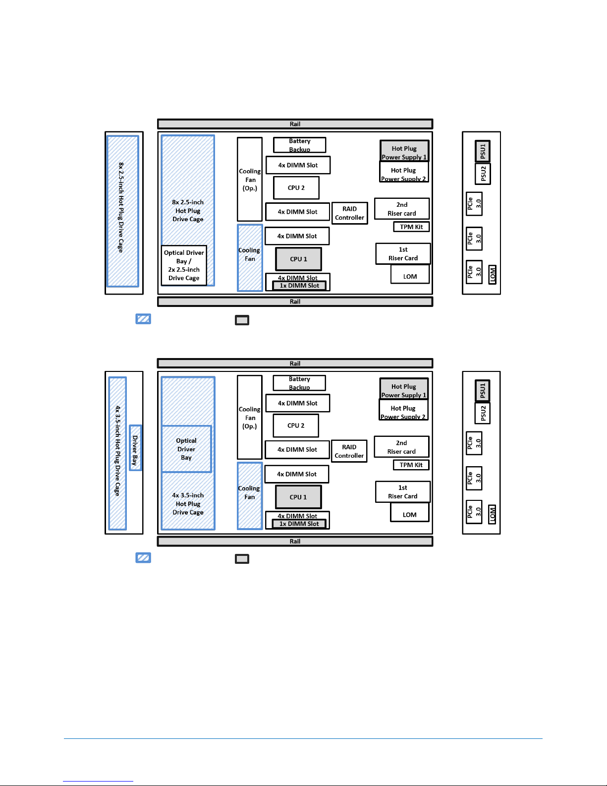
Configuration Diagram
8x 2.5-inch Drive Model
Legend: Standard Components Mandatory Components
4x 3.5-inch Drive Model
Legend: Standard Components Mandatory Components
Page 7

SYSTEM CONFIGURATION GUIDE – NEC Express5800/R120h-1E
NEC Corporation Revision 2.0 – December 2017 7
Server Configuration
1 Base Models
Product Name / Description
Part Number
NEC Express5800/R120h-1E 8x 2.5-inch Drive Model
no processor, no RAM, no HDD, no ODD, no Rail, no Power Supply Unit, no Riser Card Kit.
Including : Front Bezel, 1x 2.5-inch Drive Cage, no Riser Card Kit
N8100-2602F
NEC Express5800/R120h-1E 4x 3.5-inch Drive Model
no processor, no RAM, no HDD, no ODD, no Rail, no Power Supply Unit, no Riser Card Kit.
Including : Front Bezel, 3.5-inch Drive Cage
N8100-2603F
NOTE:
The base model must be ordered with a processor kit, a memory kit, SAS/SATA cable, a power supply kit and Rail.
2 Processors
Available sockets: 2
Category
Product Name / Description
Part Number
Xeon®
Bronze 3100
Series
Xeon Bronze 3104 Processor Kit
Intel® Xeon ® Bronze 3104 (1.70 GHz, 6C/6T, 8.25MB, TDP 85W)
N8101-1275 (1st)
N8101-1276 (2nd)
Xeon Bronze 3106 Processor Kit
Intel® Xeon ® Bronze 3106 (1.70 GHz, 8C/8T, 11MB, TDP 85W)
N8101-1277 (1st)
N8101-1278 (2nd)
Xeon®
Silver 4100
Series
Xeon Silver 4108 Processor Kit
Intel® Xeon ® Silver 4108 (1.80 GHz, 8C/16T, 11MB, TDP 85W)
N8101-1279 (1st)
N8101-1280 (2nd)
Xeon Silver 4110 Processor Kit
Intel® Xeon ® Silver 4110 (2.10 GHz, 8C/16T, 11MB, TDP 85W)
N8101-1281 (1st)
N8101-1282 (2nd)
Xeon Silver 4112 Processor Kit
Intel® Xeon ® Silver 4112 (2.60 GHz, 4C/8T, 8.25MB, TDP 85W)
N8101-1283 (1st)
N8101-1284 (2nd)
Xeon Silver 4114 Processor Kit
Intel® Xeon ® Silver 4114 (2.20 GHz, 10C/20T, 13.75MB, TDP 85W)
N8101-1287 (1st)
N8101-1288 (2nd)
Xeon Silver 4116 Processor Kit
Intel® Xeon ® Silver 4116 (2.10 GHz, 12C/24T, 16.50MB, TDP 85W)
N8101-1289 (1st)
N8101-1290 (2nd)
Xeon®
Gold 5100
Series
Xeon Gold 5115 Processor Kit
Intel® Xeon ® Gold 5115 (2.40 GHz, 10C/20T, 13.75MB, TDP 85W)
N8101-1291 (1st)
N8101-1292 (2nd)
Xeon Gold 5118 Processor Kit
Intel® Xeon ® Gold 5118 (2.30 GHz, 12C/24T, 16.50MB, TDP 105W)
N8101-1293 (1st)
N8101-1294 (2nd)
Xeon Gold 5120 Processor Kit
Intel® Xeon ® Gold 5120 (2.20 GHz, 14C/28T, 19.25MB, TDP 105W)
N8101-1295 (1st)
N8101-1296 (2nd)
Xeon Gold 5122 Processor Kit
Intel® Xeon ® Gold 5122 (3.60 GHz, 4C/8T, 16.50MB, TDP 105W)
N8101-1297 (1st)
N8101-1298 (2nd)
Xeon®
Gold 6100
Series
Xeon Gold 6126 Processor Kit
Intel® Xeon ® Gold 6126 (2.60 GHz, 12C/24T, 19.25MB, TDP 125W)
N8101-1299 (1st)
N8101-1300 (2nd)
Xeon Gold 6128 Processor Kit
Intel® Xeon ® Gold 6128 (3.40 GHz, 6C/12T, 19.25MB, TDP 115W)
N8101-1301 (1st)
N8101-1302 (2nd)
Xeon Gold 6130 Processor Kit
Intel® Xeon ® Gold 6130 (2.10 GHz, 16C/32T, 22MB, TDP 125W)
N8101-1303 (1st)
N8101-1304 (2nd)
Xeon Gold 6132 Processor Kit
Intel® Xeon ® Gold 6132 (2.60 GHz, 14C/28T, 19.25MB, TDP 140W)
N8101-1305 (1st)
N8101-1306 (2nd)
Xeon Gold 6134 Processor Kit
Intel® Xeon ® Gold 6134 (3.20 GHz, 8C/16T, 24.75MB, TDP 130W)
N8101-1307 (1st)
N8101-1308 (2nd)
Xeon Gold 6136 Processor Kit
Intel® Xeon ® Gold 6136 (3 GHz, 12C/24T, 24.75MB, TDP 150W)
N8101-1480 (1st)
N8101-1481 (2nd)
Xeon Gold 6138 Processor Kit
Intel® Xeon ® Gold 6138 (2 GHz, 20C/40T, 27.50MB, TDP 125W)
N8101-1309 (1st)
N8101-1310 (2nd)
Xeon Gold 6140 Processor Kit
Intel® Xeon ® Gold 6140 (2.30 GHz, 18C/36T, 24.75MB, TDP 140W)
N8101-1311 (1st)
N8101-1312 (2nd)
Xeon Gold 6142 Processor Kit
Intel® Xeon ® Gold 6142 (2.60 GHz, 16C/32T, 22MB, TDP 150W)
N8101-1482 (1st)
N8101-1483 (2nd)
Xeon Gold 6148 Processor Kit
Intel® Xeon ® Gold 6148 (2.40 GHz, 20C/40T, 27.50MB, TDP 150W)
N8101-1484 (1st)
N8101-1485 (2nd)
Page 8

SYSTEM CONFIGURATION GUIDE – NEC Express5800/R120h-1E
NEC Corporation Revision 2.0 – December 2017 8
Category
Product Name / Description
Part Number
Xeon Gold 6152 Processor Kit
Intel® Xeon ® Gold 6152 (2.10 GHz, 22C/44T, 30.25MB, TDP 140W)
N8101-1313 (1st)
N8101-1314 (2nd)
Xeon®
Platinum 8100
Series
Xeon Platinum 8160 Processor Kit
Intel® Xeon ® Platinum 8160 (2.10 GHz, 24C/48T, 33MB, TDP 150W)
N8101-1315 (1st)
N8101-1316 (2nd)
Xeon Platinum 8164 Processor Kit
Intel® Xeon ® Platinum 8164 (3 GHz, 26C/52T, 35.75MB, TDP 150W)
N8101-1317 (1st)
N8101-1318 (2nd)
NOTE:
The processor kit for the 1st CPU must be ordered with a base model.
The processors must be the same to configure dual processor system.
The maximum number of logical processors supported by OS
See the table below for the maximum number of logical processors that you can actually use on your system.
Operating Systems
Number of Logical
Processors Supported
by Operating Systems
Maximum Available
Number of Logical
Processors
Microsoft Windows Server 2012 R2 Standard
Microsoft Windows Server 2012 R2 Datacenter
640 1
104
Microsoft Windows Server 2016 Standard
Microsoft Windows Server 2016 Datacenter
640 1
104
VMware ESXi 6.0
480
104
VMware ESXi 6.5
576
104
1
The maximum numbers of logical processors when using Hyper-V are below:
- Windows Server 2012 R2: 320
- Windows Server 2016: 512
Page 9

SYSTEM CONFIGURATION GUIDE – NEC Express5800/R120h-1E
NEC Corporation Revision 2.0 – December 2017 9
3 Memory
Available slots: 8 per processor
Category
Product Name / Description
Part Number
Registered DIMM
(RDIMM)
8GB DDR4-2666 REG Memory Kit (1x8GB/SR)
1 x 8GB Registered ECC DIMM, DDR4-2666(PC4-2666), Single Rank
N8102-708
16GB DDR4-2666 REG Memory Kit (1x16GB/SR)
1 x 16GB Registered ECC DIMM, DDR4-2666(PC4-2666), Single Rank
N8102-709
16GB DDR4-2666 REG Memory Kit (1x16GB/DR)
1 x 16GB Registered ECC DIMM, DDR4-2666(PC4-2666), Dual Rank
N8102-710
32GB DDR4-2666 REG Memory Kit (1x32GB/DR)
1 x 32GB Registered ECC DIMM, DDR4-2666(PC4-2666), Dual Rank
N8102-711
Load Reduced DIMM
(LRDIMM)
64GB DDR4-2666 LR Memory Kit (1x64GB/QR)
1 x 64GB Load Reduced ECC DIMM, DDR4-2666(PC4-2666), Quad
Rank
N8102-712
NOTE:
Minimum one memory kit per processor must be installed.
It is recommended to install memory kits in multiples of 6 identical DIMMs for 6-channel symmetric memory configurations to
increase memory transfer speed.
Mix configurations of RDIMM and LRDIMM are not supported.
Memory Configuration Feature Comparison
See the table below for feature comparisons of memory configurations supported.
Independent Channel
Memory Sparing
Memory Mirroring
Performance
Best
Better
Good
Data Protection
No
Multiple single bit error
protection
Multiple single bit and multi bit
error protection
Redundancy
No
Partly
Fully
Data Correction
ECC, x4 SDDC
ECC, x4 SDDC
ECC, x4 SDDC
Available Memory
Full physical memory
Two ranks of memory per
channel : Half physical
memory
Four ranks of memory per
channel : 3/4 physical memory
Eight ranks of memory per
channel : 7/8 physical memory
Half physical memory
Available Memory
Channels
6 6 6
Notes
-
All DIMMs in the system must
be identical.
All DIMMs in the system must
be identical.
Maximum Memory Speed
See the table below for the actual maximum memory transfer speed. DDR4 memory speed depends on the native memory bus
speed of the memory controller.
Processor Type
DIMM Speed
Xeon ® Platinum 8100 series
Xeon ® Gold 6100 series
Xeon ® Gold 5122 Processor
2666 MHz
Xeon ® Gold 5100 series excluding Xeon ® Gold 5122 Processor
Xeon ® Silver 4100 series
2400 MHz
Xeon ® Bronze 3100 series
2133 MHz
Page 10

SYSTEM CONFIGURATION GUIDE – NEC Express5800/R120h-1E
NEC Corporation Revision 2.0 – December 2017 10
Maximum Available Memory
See the table below for the maximum memory size that you can actually use on your system.
Operating Systems
Maximum Memory
Size Supported by
Operating Systems
Maximum Available
Memory
Microsoft Windows Server 2012 R2 Standard
Microsoft Windows Server 2012 R2 Datacenter
4 TB
1 TB 1
Microsoft Windows Server 2016 Standard
Microsoft Windows Server 2016 Datacenter
24 TB
1 TB 1
VMware ESXi 6.0
6 TB
1 TB 2
VMware ESXi 6.5
12TB
1 TB 3
1
The maximum available memory size of Hyper-V systems is below:
- Windows Server 2012 R2 : 4 TB
- Windows Server 2016 : 24 TB
2
Up to 4 TB of the main memory is available to each virtual machine.
3
Up to 6 TB of the main memory is available to each virtual machine.
Page 11
SYSTEM CONFIGURATION GUIDE – NEC Express5800/R120h-1E
NEC Corporation Revision 2.0 – December 2017 11
4 Internal Storage
Drive Configuration
Choose appropriate drive model and optional drive cages in accordance with the type and number of the drive you want to install.
Drive Bay for 2.5-inch Drive Model
Eight 2.5-inch drive bays are standard. With an optional 2.5-inch drive cage, up to 10 2.5-inch drive bays can be equipped.
Drive Bay for 3.5-inch Drive Model
Four 3.5-inch drive bays are equipped as standard
Optional Drive Cages
Category
Product Name / Description
Part Number
Factory Integration
option
2.5-inch Hot Plug Drive Cage Kit
Including internal cable, for 8x 2.5-inch Drive Model
NOTE:
- The Drive Cage Kit does not include internal cables. Choose the
appropriate interface cable in accordance with the type of storage
controllers.
N8154-126
Field upgrade option
2.5-inch Hot Plug Drive Cage Kit
Including internal cables, for 8x 2.5-inch Drive Model
N8154-102
Page 12

SYSTEM CONFIGURATION GUIDE – NEC Express5800/R120h-1E
NEC Corporation Revision 2.0 – December 2017 12
Storage Controllers and Options
Embedded SATA Controller
Category
Product Name / Description
Part Number
Storage Controller
Embedded SATA Controller
10 x 6Gb/s SATA
(Standard)
Cable
2.5-inch
Drive Mode
Internal SAS/SATA Cable
For 2.5-inch Drive Model , 2x [1 x mini-SAS to 1 x mini-SAS]
K410-379(00)
Internal SAS/SATA Cable
For optional 2.5-inch Drive Cage, 1x [1x mini-SAS to 1 x mini-SAS]
K410-427(00)
3.5-inch
Drive Mode
Internal SAS/SATA Cable
For 3.5-inch Drive Model, 2x [1 x mini-SAS to 1 x mini-SAS]
K410-429(00)
NOTE:
For factroy installation, up to eight drives can be installed in the system.
All internal SATA cables are factory integrated options.
Hot plug insertion/removal are not supported in the configuration.
Embedded SATA RAID Controller (RAID 0/1/10)
Category
Product Name / Description
Part Number
Storage Controller
Embedded SATA Controller
10 x 6Gb/s SATA
(Standard)
Cable
2.5-inch
Drive Model
Internal SAS/SATA Cable
For 2.5-inch Drive Model , 2x [1 x mini-SAS to 1 x mini-SAS]
K410-379(00)
Internal SAS/SATA Cable
For optional 2.5-inch Drive Cage, 1x [1x mini-SAS to 1 x mini-SAS]
K410-427(00)
3.5-inch
Drive Model
Internal SAS/SATA Cable
For 3.5-inch Drive Model, 2x [1 x mini-SAS to 1 x mini-SAS]
K410-429(00)
NOTE:
For factroy installation, up to eight drives can be installed in the system.
The Embedded SATA RAID Controller is available for Windows operating system only.
When you use the Embedded SATA RAID controller, choose an external DVD drive. An internal DVD drive requires the embedded
SATA controller configuration.
RAID Controller for Dedicated PCI Slot
Choose the appropriate RAID controller in accordance with RAID feature required.
Category
Product Name / Description
Part Number
Storage Controller
RAID Controller (RAID 0/1)
RAID 0/1/10 and SAS HBA mode, 0MB, Int. 8 port, PCIe 3.0 x8, SAS
12Gb/s, SATA 6Gb/s, Low Profile Heat Sink
N8103-192
RAID Controller (2GB, RAID 0/1/5/6)
RAID 0/1/5/6/10/50/60, 2GB, Int. 8 port, PCIe 3.0 x8, SAS 12Gb/s,
SATA 6Gb/s, Low Profile Heat Sink
N8103-193
Battery Backup
Battery Backup Unit
Lithium-ion Battery for RAID controller with cache memory
N8103-198
Cable
2.5-inch Drive
Model
Internal SAS/SATA Cable
For 2.5-inch Drive Model
K410-380(00)
3.5-inch Drive
Model
Internal SAS/SATA Cable
For 3.5-inch Drive Model
K410-381(00)
NOTE:
PCI slot #2 is not available when a RAID controller is installed into the RAID slot.
One battery backup unit must be installed per one system.
Page 13

SYSTEM CONFIGURATION GUIDE – NEC Express5800/R120h-1E
NEC Corporation Revision 2.0 – December 2017 13
RAID Controller for Standard PCI Slot
Category
Product Name / Description
Part Number
Storage Controller
RAID Controller (RAID 0/1)
RAID 0/1/10 and SAS HBA mode, 0MB, Int. 8, PCIe 3.0 x8, SAS
12Gb/s, SATA 6Gb/s, Standard H/S type
N8103-195
RAID Controller (2GB, RAID 0/1/5/6)
RAID 0/1/5/6/10/50/60, 2GB, Int. 8, PCIe 3.0 x8, SAS 12Gb/s, SATA
6Gb/s, Standard H/S type
N8103-201
Battery Backup
Battery Backup Unit
Lithium-ion Battery for RAID controller with cache memory
N8103-198
Cable
2.5-inch Drive
Model
Internal SAS/SATA Cable
For 2.5-inch Drive Model
K410-380(00)
3.5-inch Drive
Model
Internal SAS/SATA Cable
For 3.5-inch Drive Model
K410-381(00)
NOTE:
The RAID controller must be installed after shipment.
One battery backup unit must be installed per one system.
Internal Drives
2.5-inch SATA Hard Disk Drives
Category
Product Name / Description
Part Number
512e Sector/
7,200 rpm
1TB 7.2K Hot Plug 2.5-inch SATA HDD
1 x 1 TB SATA HDD, 2.5-inch, 6Gb/s, 7,200 rpm, 512e sector
N8150-544
2TB 7.2K Hot Plug 2.5-inch SATA HDD
1 x 2 TB SATA HDD, 2.5-inch, 6Gb/s, 7,200 rpm, 512e sector
N8150-545
NOTE:
512e sector drives are not available for VMware ESXi system.
All drives within a RAID array should be of the same type, capacity and rotation speed.
Up to two kinds of drives selected from SAS 10K HDDs, SAS 15K HDDs, SATA HDDs, SATA SSDs can be mixed.
2.5-inch SATA Solid State Drives
Category
Product Name / Description
Part Number
Read Intensive
240GB Hot Plug 2.5-inch SATA SSD
1 x 240GB SATA SSD, 2.5-inch, 6Gb/s, 512n sector, Read Intensive
N8150-743
480GB Hot Plug 2.5-inch SATA SSD
1 x 480GB SATA SSD, 2.5-inch, 6Gb/s, 512n sector, Read Intensive
N8150-744
960GB Hot Plug 2.5-inch SATA SSD
1 x 960GB SATA SSD, 2.5-inch, 6Gb/s, 512n sector, Read Intensive
N8150-745
1.92TB Hot Plug 2.5-inch SATA SSD
1 x 1.92TB SATA SSD, 2.5-inch, 6Gb/s, 512n sector, Read Intensive
N8150-746
3.84TB Hot Plug 2.5-inch SATA SSD
1 x 3.84TB SATA SSD, 2.5-inch, 6Gb/s, 512n sector, Read Intensive
N8150-747
Value Endurance
240GB Hot Plug 2.5-inch SATA SSD
1 x 240GB SATA SSD, 2.5-inch, 6Gb/s, 512n sector, Value Endurance
N8150-739
480GB Hot Plug 2.5-inch SATA SSD
1 x 480GB SATA SSD, 2.5-inch, 6Gb/s, 512n sector, Value Endurance
N8150-740
960GB Hot Plug 2.5-inch SATA SSD
1 x 960GB SATA SSD, 2.5-inch, 6Gb/s, 512n sector, Value Endurance
N8150-741
1.92TB Hot Plug 2.5-inch SATA SSD
1 x 1.92TB SATA SSD, 2.5-inch, 6Gb/s, 512n sector, Value Endurance
N8150-742
NOTE:
All drives within a RAID array should be of the same type, capacity.
Up to two kinds of drives selected from SAS 10K HDDs, SAS 15K HDDs, SATA HDDs, SATA SSDs and SAS SSDs can be mixed.
Page 14

SYSTEM CONFIGURATION GUIDE – NEC Express5800/R120h-1E
NEC Corporation Revision 2.0 – December 2017 14
2.5-inch SAS Hard Disk Drives
Category
Product Name / Description
Part Number
512n Sector /
10,000 rpm
300GB Hot Plug 2.5-inch SAS HDD
1 x 300 GB SAS HDD, 2.5-inch, 12Gb/s, 10,000 rpm, 512n sector
N8150-546
600GB Hot Plug 2.5-inch SAS HDD
1 x 600 GB SAS HDD, 2.5-inch, 12Gb/s, 10,000 rpm, 512n sector
N8150-547
1.2TB Hot Plug 2.5-inch SAS HDD
1 x 1.2TB SAS HDD, 2.5-inch, 12Gb/s, 10,000 rpm, 512n sector
N8150-549
512e Sector /
10,000 rpm
1.8TB Hot Plug 2.5-inch SAS HDD
1 x 1.8TB SAS HDD, 2.5-inch, 12Gb/s, 10,000 rpm, 512e sector
N8150-550
512n Sector /
15,000 rpm
300GB 15K Hot Plug 2.5-inch SAS HDD
1x 300 GB SAS HDD, 2.5-inch, 12Gb/s, 15,000 rpm, 512n sector
N8150-551
600GB 15K Hot Plug 2.5-inch SAS HDD
1x 600 GB SAS HDD, 2.5-inch, 12Gb/s, 15,000 rpm, 512n sector
N8150-552
512e Sector /
15,000 rpm
900GB 15K Hot Plug 2.5-inch SAS HDD
1x 900 GB SAS HDD, 2.5-inch, 12Gb/s, 15,000 rpm, 512e sector
N8150-553
NOTE:
512e sector drives are not available for VMware ESXi system.
All drives within a RAID array should be of the same type, capacity and rotation speed.
Up to two kinds of drives selected from SAS 10K HDDs, SAS 15K HDDs, SATA HDDs, SATA SSDs and SAS SSDs can be mixed.
To configure a large-capacity RAID array, it is recommended to configure in RAID 6 or RAID 60 in order to minimize the risk of
becoming multiple hard drives failure during the RAID rebuilding process.
2.5-inch SAS Solid State Drives
Category
Product Name / Description
Part Number
Middle Endurance
400GB Hot Plug 2.5-inch SAS SSD
1 x 400GB SAS SSD, 2.5-inch, 12Gb/s, 512n sector, Middle Endurance
N8150-748
800GB Hot Plug 2.5-inch SAS SSD
1 x 800GB SAS SSD, 2.5-inch, 12Gb/s, 512n sector, Middle Endurance
N8150-749
Value Endurance
400GB Hot Plug 2.5-inch SAS SSD
1 x 400GB SAS SSD, 2.5-inch, 12Gb/s, 512n sector, Value Endurance
N8150-750
800GB Hot Plug 2.5-inch SAS SSD
1 x 800GB SAS SSD, 2.5-inch, 12Gb/s, 512n sector, Value Endurance
N8150-751
480GB Hot Plug 2.5-inch SAS SSD
1 x 480GB SAS SSD, 2.5-inch, 12Gb/s, 512n sector, Value Endurance
N8150-752
960GB Hot Plug 2.5-inch SAS SSD
1 x 960GB SAS SSD, 2.5-inch, 12Gb/s, 512n sector, Value Endurance
N8150-753
NOTE:
All drives within a RAID array should be of the same type, capacity and rotation speed.
Up to two kinds of drives selected from SAS 10K HDDs, SAS 15K HDDs, SATA HDDs, SATA SSDs and SAS SSDs can be mixed.
To configure a large-capacity RAID array, it is recommended to configure in RAID 6 or RAID 60 in order to minimize the risk of
becoming multiple hard drives failure during the RAID rebuilding process.
3.5-inch SATA Hard Disk Drives
Category
Product Name / Description
Part Number
512n Sector/
7,200 rpm
1TB 7.2K Hot Plug 3.5-inch SATA HDD
1 x 1 TB SATA HDD, 3.5-inch, 6Gb/s, 7,200 rpm, 512n sector
N8150-565
2TB 7.2K Hot Plug 3.5-inch SATA HDD
1 x 2 TB SATA HDD, 3.5-inch, 6Gb/s, 7,200 rpm, 512n sector
N8150-566
3TB 7.2K Hot Plug 3.5-inch SATA HDD
1 x 3 TB SATA HDD, 3.5-inch, 6Gb/s, 7,200 rpm, 512n sector
N8150-567
4TB 7.2K Hot Plug 3.5-inch SATA HDD
1 x 4 TB SATA HDD, 3.5-inch, 6Gb/s, 7,200 rpm, 512n sector
N8150-568
512e Sector/
7,200 rpm
6TB 7.2K Hot Plug 3.5-inch SATA HDD
1 x 6 TB SATA HDD, 3.5-inch, 6Gb/s, 7,200 rpm, 512e sector
N8150-569
8TB 7.2K Hot Plug 3.5-inch SATA HDD
1 x 8 TB SATA HDD, 3.5-inch, 6Gb/s, 7,200 rpm, 512e sector
N8150-570
10TB 7.2K Hot Plug 3.5-inch SATA HDD
N8150-571
Page 15

SYSTEM CONFIGURATION GUIDE – NEC Express5800/R120h-1E
NEC Corporation Revision 2.0 – December 2017 15
1 x 10 TB SATA HDD, 3.5-inch, 6Gb/s, 7,200 rpm, 512e sector
NOTE:
512e sector drives are not available for VMware ESXi system.
All drives within a RAID array should be of the same type, capacity.
To configure a large-capacity RAID array, it is recommended to configure in RAID 6 or RAID 60 in order to minimize the risk of
becoming multiple hard drives failure during the RAID rebuilding process.
3.5-inch Near Line SAS Hard Disk Drives
Category
Product Name / Description
Part Number
512e Sector
4TB 7.2K Hot Plug 3.5-inch SAS HDD
1 x 4 TB Near Line SAS HDD, 3.5-inch, 12Gb/s, 7,200 rpm, 512e sector
N8150-572
8TB 7.2K Hot Plug 3.5-inch SAS HDD
1 x 8 TB Near Line SAS HDD, 3.5-inch, 12Gb/s, 7,200 rpm, 512e sector
N8150-573
10TB 7.2K Hot Plug 3.5-inch SAS HDD
1 x 10 TB Near Line SAS HDD, 3.5-inch, 12Gb/s, 7,200 rpm,
512e sector
N8150-574
NOTE:
512e sector drives are not available for VMware ESXi system.
All drives within a RAID array should be of the same capacity.
To configure a large-capacity RAID array, it is recommended to configure in RAID 6 or RAID 60 in order to minimize the risk of
becoming multiple hard drives failure during the RAID rebuilding process.
Near Line SAS HDD (7200 rpm) and SAS-HDD (10,000rpm / 15,000rpm) are the same in maximum transfer speed and error
recovery capabilities, however the Near Line SAS HDD and SATA HDDs(7.200rpm) are the same in I/O performance and life.
Page 16

SYSTEM CONFIGURATION GUIDE – NEC Express5800/R120h-1E
NEC Corporation Revision 2.0 – December 2017 16
5 Optical Drive
Category
Product Name / Description
Part Number
Internal
Installation
Kit
Internal DVD Drive Installation Kit
Installation kit for 8x2.5-inch Drive Model
NOTE:
- The Installation Kit cannot be installed if N8154-102/126 2x2.5-inch Hot
Plug Drive Cage Kit (SAS/SATA) is installed.
N8154-125
Drive
Internal Slim DVD-ROM drive
Slim DVD-ROM drive
N8151-137
Internal DVD-SuperMulti Drive
Slim DVD Super Multi drive, including writing software
N8151-138
External
External DVD-ROM Drive
Slim DVD-ROM drive, Bus powered, 1.6A required
N8160-102
NOTE:
When you use the Embedded SATA RAID controller, choose an external DVD drive. An internal DVD drive requires the embedded
SATA controller configuration.
Page 17

SYSTEM CONFIGURATION GUIDE – NEC Express5800/R120h-1E
NEC Corporation Revision 2.0 – December 2017 17
6 PCI Card
Please refer to Supported PCI Cards and Installable Slots with regard to the position of PCI slot which can mount PCI card
supported.
PCI Riser Card
PCI Slot Configuration
Choose the appropriate configuration in accordance with the number and the type of PCI cards you want to install and whether you
need PCIe SSD slot and ALOM slot.
PCI Riser Card Kit
Category
Product Name / Description
Part Number
1st Riser
Riser Card Kit(2xPCI)
Riser card for slot 1 with one PCIe 3.0 x16 slot, and riser card for slot 2
with one PCIe 3.0 x8 slot
N8116-71
Riser Card Kit(2xPCI, 1xPCIe SSD)
Riser card for slot 1 with one PCIe SSD slot and one ALOM slot, and
riser card for slot 2 with PCIe 3.0 x8 slot
N8116-82
2nd Riser
Riser Card Kit(1xPCI)
Riser card for slot 3 with one PCIe 3.0 x16 slot
NOTE:
- To install 2nd Riser Card Kit, the system must be configured with a dual
processor.
- The 2nd Riser Card Kit is available if the 1st Riser Card is installed.
- The 2nd Riser Card Kit is not available if the RAID controller for
dedicated slot is installed.
N8116-72
Network Interface Controller
Category
Product Name / Description
Part Number
LOM Card
(FLOM Slot)
1GbE
Dual Port 1000BASE-T LOM Card
Integrated into Intel C622 chipset
N8104-193
10GbE
Dual Port 10GBASE-T LOM Card
Integrated into Intel C622 chipset
N8104-195
Dual Port 10GBASE-SR LOM Card
Integrated into Intel C622 chipset
NOTE:
- N8104-189 SFP+ Module is required to connect with an optical cable.
- Up to two SFP+ Modules can be installed.
N8104-194
LOM Card
(ALOM Slot)
1GbE
Quad Port 1000BASE-T LOM Card
Broadcom BCM5719
PCIe 2.0(x4)
N8104-171
Quad Port 1000BASE-T LOM Card
Intel Ethernet Controller I350
PCIe 2.0(x4)
N8104-172
10GbE
Dual Port 10GBASE-T LOM Card
QLogic 57810S
PCIe 2.0(x8)
N8104-173
Dual Port 10GBASE-T LOM Card
Intel X550
PCIe 2.0(x8)
N8104-175
Dual Port 10GBASE SFP+ LOM Card
Intel Ethernet Controller X710
PCIe 3.0(x8)
NOTE:
- N8104-189 SFP+ Module is required to connect with an optical cable.
- Up to two SFP+ Modules can be installed.
N8104-176
25GbE
Dual Port 25GBASE SFP+ LOM Card
Cavium 45604
PCIe 3.0(x16)
N8104-177
Page 18

SYSTEM CONFIGURATION GUIDE – NEC Express5800/R120h-1E
NEC Corporation Revision 2.0 – December 2017 18
Category
Product Name / Description
Part Number
NOTE:
- N8104-190 SFP28 Module is required to connect with an optical cable.
- Up to 2 SFP28 Modules can be installed.
Adapter
1GbE
Dual Port 1000BASE-T Adapter
Broadcom BCM5720 Gigabit Ethernet Controller
PCIe 2.0(x1)
N8104-178
Dual Port 1000BASE-T Adapter
Intel Ethernet Controller I350
PCIe 2.0(x4)
NOTE:
- Network cables with RJ-45 plug covers cannot be used.
N8104-180
Quad Port 1000BASE-T Adapter
Broadcom BCM5719 Gigabit Ethernet Controller
PCIe 2.0(x4)
NOTE:
- Network cables with RJ-45 plug covers cannot be used.
N8104-179
Quad Port 1000BASE-T Adapter
Intel Ethernet Controller I350
PCIe 2.0(x4)
NOTE:
- Network cables with RJ-45 plug covers cannot be used.
N8104-181
10GbE
Dual Port 10GBASE-T Adapter
QLogic 57810S
PCIe 2.0(x8)
N8104-182
Dual Port 10GBASE-T Adapter
Cavium QL41401,
PCIe3.0(x8)
N8104-183
Dual Port 10GBASE-T Adapter
Intel X550-AT2,
PCIe3.0(x4)
N8104-184
Dual Port 10GBASE SFP+ Adapter
QLogic 57810S
PCIe 2.0(x8)
NOTE:
- N8104-189 SFP+ Module is required to connect with an optical cable.
- Up to 2 SFP+ Modules can be installed.
N8104-185
Dual Port 10GBASE SFP+ Adapter
Intel Ethernet Controller X710
PCIe 3.0(x8)
NOTE:
- N8104-189 SFP+ Module is required to connect with an optical cable.
- Up to 2 SFP+ Modules can be installed.
N8104-186
25GbE
Dual Port 25GBASE SFP28 Adapter
Cavium QL41401,
PCIe3.0(x8)
NOTE:
- N8104-190 SFP28 Module is required to connect with an optical cable.
- Up to 2 SFP28 Modules can be installed.
N8104-187
Quad Port 25GBASE QSFP28 Adapter
Cavium 45604
PCIe 3.0(x16)
NOTE:
- N8104-191 QSFP28 Module is required to connect with an optical cable.
- Up to 1 QSFP28 Modules can be installed.
N8104-188
SFP
Module
10GbE
SFP+ Module (10G-SR)
1 x SFP+ Module
N8104-189
25GbE
SFP28 Module(25G-SR)
1 x SFP28 Module
N8104-190
QSFP28 Module(100G-SR4)
1 x QSFP28 Module
N8104-191
NOTE:
The NIC cards must be installed under the maximum configuration limits for networking when running with VMware systems. For
more detail, see the Networking Maximum in the Configuration Maximums document for VMware.
Page 19

SYSTEM CONFIGURATION GUIDE – NEC Express5800/R120h-1E
NEC Corporation Revision 2.0 – December 2017 19
- For VMware ESXi 6.0: https://www.vmware.com/pdf/vsphere6/r60/vsphere-60-configuration-maximums.pdf
- For VMware ESXi 6.5: https://www.vmware.com/pdf/vsphere6/r65/vsphere-65-configuration-maximums.pdf
NIC Teaming feature – NIC Teaming and bonding features
See the table below for supported network interfaces and OS combinations.
Network Interface
Team
Operating Systems
1GbE NIC
On-board LAN Interface
N8104-172/-180/-181/-193
Up to four ports per one team
Windows Server 2012 R2
Windows Server 2016
Red Hat Enterprise Linux 7
VMware ESXi 6.5
1GbE NIC
N8104-171/-178/-179
Up to four ports per one team
Windows Server 2016
Red Hat Enterprise Linux 7
VMware ESXi 6.0
VMware ESXi 6.5
10GbE NIC
N8104-173/-182
Up to four ports per one team
Windows Server 2012 R2
Windows Server 2016
Red Hat Enterprise Linux 7
VMware ESXi 6.0
VMware ESXi 6.5
10GbE NIC
N8104-175/-184/-195
Up to four ports per one team
Windows Server 2012 R2
Windows Server 2016
Red Hat Enterprise Linux 7
VMware ESXi 6.0
VMware ESXi 6.5
10GbE NIC
N8104-183
Up to four ports per one team
Windows Server 2012 R2
Windows Server 2016
Red Hat Enterprise Linux 7
VMware ESXi 6.0
VMware ESXi 6.5
10GbE NIC
N8104-185
Up to four ports per one team
Windows Server 2012 R2
Windows Server 2016
Red Hat Enterprise Linux 7
VMware ESXi 6.0
VMware ESXi 6.5
10GbE NIC
N8104-176/-186/-194
Up to four ports per one team
Windows Server 2012 R2
Windows Server 2016
Red Hat Enterprise Linux 7
VMware ESXi 6.5
25GbE NIC
N8104-188
Up to four ports per one team
Windows Server 2012 R2
Windows Server 2016
Red Hat Enterprise Linux 7
NOTE:
When 1GbE, 10GbE and 25GbE NIC teams are mixed, the maximum number of teams must be five per one system.
External Storage Controller
RAID Controller
Category
Product Name / Description
Part Number
Controller
RAID Controller (4GB, RAID0/1/5/6)
RAID0/1/5/6/10/50/60, 4GB, 8 External port PCIe 3.0 x8,
SAS 12Gb/s, SATA 6Gb/s
N8103-196
Battery Backup
Battery Backup Unit
Lithium-ion Battery for RAID controller.
N8103-198
NOTE:
Only one SAS JBOD Enclosure can be connected to one RAID controller.
4Kn sector drives are not supported with the RAID controller.
One battery backup unit must be installed per one system.
To configure a large-capacity RAID array, it is recommended to configure in RAID 6 or RAID 60 in order to minimize the risk of
becoming multiple hard drives failure during the RAID rebuilding process.
It is recommended to set RAID array configuration drives less than eight in order to minimize the risk of becoming multiple hard
drives failure.
Page 20

SYSTEM CONFIGURATION GUIDE – NEC Express5800/R120h-1E
NEC Corporation Revision 2.0 – December 2017 20
Fibre Channel / SAS Controller
Category
Product Name / Description
Part Number
Fibre Channel
Fibre Channel Controller (1ch)
Cavium QLogic, QLE2690
16Gb/s, Optical, PCIe 3.0 x8
N8190-165
Fibre Channel Controller (2ch)
Cavium QLogic, QLE2692
16Gb/s, Optical, PCIe 3.0 x8
N8190-166
Fibre Channel Controller (1ch)
Broadcom, LPe31000
16Gb/s, Optical, PCIe 3.0 x8
N8190-163
Fibre Channel Controller (2ch)
Broadcom, LPe31002
16Gb/s, Optical, PCIe 3.0 x8
N8190-164
Fibre Channel Controller (1ch)
Broadcom, LPe32000
32Gb/s, Optical, PCIe 3.0 x8
N8190-171
Fibre Channel Controller (2ch)
Broadcom, LPe32002
32Gb/s, Optical, PCIe 3.0 x8
N8190-172
SAS
SAS Controller
LSI SAS9300-8e Host Bus Adapter
12Gb/s SAS, ext. 8(SFF-8644 x2), PCIe 3.0(x8)
NOTE:
- The SAS Controller must be installed after shipment.
N8103-184
SAS Controller
12Gb/s SAS, ext. 8(SFF-8644 x2), PCIe 3.0 x8
N8103-197
Serial Port Adapter
Product Name / Description
Part Number
Additional Serial Port Kit
Serial port Connector
N8117-11
NOTE:
Up to one Serial Port Adapter can be installed.
Page 21

SYSTEM CONFIGURATION GUIDE – NEC Express5800/R120h-1E
NEC Corporation Revision 2.0 – December 2017 21
7 Other Add-in Components
Power Supply
Category
Product Name / Description
Part Number
Non
Redundant
500W Non-hot Plug Power Supply
N8181-168
Redundant
Power
Cage
Redundant PSU Cage
N8181-174
Power
Unit
500W Platinum Hot Plug Power Supply
1 x 500 Watt 80 PLUS® Platinum, including one 2m IEC320 C14 power
cord
N8181-159
800W Platinum Hot Plug Power Supply
1 x 800 Watt 80 PLUS® Platinum, including one 2m IEC320 C14 power
cord
N8181-160
800W Titanium Hot Plug Power Supply
1 x 800 Watt 80 PLUS® Titanium, including one 2m IEC320 C14 power
cord
NOTE:
- 200 VAC input only supported
N8181-161
NOTE:
Minimum one power supply kit must be installed.
The power supply kit must be the same to configure redundancy.
Available Power Supplies
See the table below for the power supplies available based on the number and type of processor, the number and type of DIMMs,
and the number of drives.
Number of
Processors
Type of Processor
Type of
DIMMs
Number of
DIMMs
Number of
Drives
Available Power
Supply
One
Processor with 130 Watt or less
- - -
500W or more
Processor with 140 Watt or more
RDIMM
- - 500W or more
LRDIMM
six or less
Up to eight
500W or more
Nine or more
800W or more
seven or more
-
800W or more
Two
Processor with 85 Watt
RDIMM
six or less
Up to four
500W or more
Five or more
800W or more
seven or more
-
800W or more
Processor with 105 Watt or more
- - -
800W or more
Cooling Fan Kit
Product Name / Description
Part Number
Non Redundant Fan Kit
Non redundant cooling fans
(Standard)
Redundant Fan Kit
Redundant cooling fans
N8181-166
Trusted Platform Module Kit
Product Name / Description
Part Number
Trusted Platform Module Kit
TPM 2.0 module
N8115-35
NOTE:
The kit is not available in China.
The kit is not removable after attachment.
The kit supports only with Windows operating system configured with UEFI boot mode.
"Chipset-TPM" in BIOS setup menu must be activated prior to use of this product.
Page 22

SYSTEM CONFIGURATION GUIDE – NEC Express5800/R120h-1E
NEC Corporation Revision 2.0 – December 2017 22
To use Windows BitLocker drive encryption, be sure to keep the "recovery password" of BitLocker function. The recovery
password is required to restore data for hardware replacement during a system error.
USB Memory Kit
Product Name / Description
Part Number
8GB USB Memory
N8106-017
Dual 8GB microSD Kit(USB)
Including 2x 8GB microSD, USB dual microSD memory card reader, RAID1 Support
N8106-016
NOTE:
The USB Memory Kit is installed in the system when you order it with the base model.
The kit does not include VMware ESXi installation media and license.
Page 23

SYSTEM CONFIGURATION GUIDE – NEC Express5800/R120h-1E
NEC Corporation Revision 2.0 – December 2017 23
8 Factory Server Setting Service
Memory RAS Settings
If you need to change the BIOS settings for the memory RAS feature in the factory, select the appropriate configuration service.
Product Name / Description
Part Number
Memory Mirroring Mode Configuration Service
Setup option to change the Memory RAS of BIOS menu to Memory Mirroring Mode
NESV16-013
Memory Sparing Mode Configuration Service
Setup option to change the Memory RAS of BIOS menu to Memory Sparing Mode
NESV16-014
Page 24

SYSTEM CONFIGURATION GUIDE – NEC Express5800/R120h-1E
NEC Corporation Revision 2.0 – December 2017 24
9 Add-on Components
17-inch LCD Console Drawer
Category
Product Name / Description
Part Number
Drawer
w/ KVM
Drawer
17-inch LCD Console Drawer (8port)
17-inch LCD, US 83-keys Keyboard, Optical mouse, 8 port KVM switch,
1U height
N8143-106F
Cable
Switch Unit Connection Cable Set (USB, 1.8m)
1.8 m, 1 x 15-pin mini D-sub to 1 x 15-pin mini D-sub / 1 x 4-pin USB A
K410-118(1A)
Switch Unit Connection Cable Set (USB, 3m)
3 m, 1 x 15-pin mini D-sub to 1 x 15-pin mini D-sub / 1 x 4-pin USB A
K410-118(03)
Switch Unit Connection Cable Set (USB, 5m)
5 m, 1 x 15-pin mini D-sub to 1 x 15-pin mini D-sub / 1 x 4-pin USB A
K410-118(05)
Drawer
w/o KVM
Drawer
17inch LCD Console Unit 1U
17-inch LCD, US 83-keys Keyboard, Optical mouse, 1U height,
4-pin USB B to 4-pin USB A cable 2 m, PS/2 Y-splitter cable 2m, 15-pin
mini D-sub VGA cable 2 m
N8143-105F
17inch LCD Console Drawer (1port)
17-inch LCD, US 103-keys Keyboard with 10-key, Touch pad with 3button, 1U height, 4-pin USB B to 4-pin USB A cable 1.8 m, Two PS/2
cable 1.8 m, 15-pin mini D-sub VGA cable 1.8 m
N8143-108F
17.3inch LCD Console Drawer (1port)
17.3-inch wide Full HD LCD, US 103-keys Keyboard with 10-key, Touch
pad with 2-button, 1U height, 4-pin USB B to 4-pin USB A cable 1.8 m,
15-pin mini D-sub VGA cable 1.8 m, DVI-D cable 1.8m
N8143-122F
Keypad
Keyboard Unit (JP)
JP 108-keys Keyboard with 10-key for N8143-108F 17inch LCD
Console Drawer (1port)
N8143-109
Keyboard Unit (UK)
UK 104-keys Keyboard with 10-key, for N8143-108F 17inch LCD
Console Drawer (1port)
N8143-111
KVM Switch
Category
Product Name / Description
Part Number
KVM Switch
Server Switch Unit (8 server)
1U USB 8 port KVM switch
N8191-14F
Cable
KVM
Switch Unit Connection Cable Set (USB,1.8m)
1.8 m, 1 x 15-pin mini D-sub to 1 x 15-pin mini D-sub / 1 x 4-pin USB A
K410-118(1A)
Switch Unit Connection Cable Set (USB,3m)
3 m, 1 x 15-pin mini D-sub to 1 x 15-pin mini D-sub / 1 x 4-pin USB A
K410-118(03)
Switch Unit Connection Cable Set (USB,3m)
5 m, 1 x 15-pin mini D-sub to 1 x 15-pin mini D-sub / 1 x 4-pin USB A
K410-118(05)
Cascading
Switch Unit Connection Cable 1.8 m
1.8 m, 1 x 15-pin mini D-sub - 1x 15-pin mini D-Sub / 2x PS/2
K410-119(1A)
Page 25

SYSTEM CONFIGURATION GUIDE – NEC Express5800/R120h-1E
NEC Corporation Revision 2.0 – December 2017 25
Server Management License
Choose the following license kit to use additional remote management future.
Product Name / Description
Part Number
License for Remote Management (Advanced)
License per server
Remote console:
- Integrated Remote Console (IRC) with full functionality
Remote media:
- Virtual media access via Integrated Remote Console (IRC)
- Scripted virtual media access
System management:
- Global team collaboration for up to six consoles
- Integrated Remote Console (IRC) recording and playback
N8115-33
License for Remote Management (Scale-Out)
License per server
Remote console:
- Text-based remote console via SSH
- Integrated Remote Console (IRC) under Pre-OS
System management:
- Email alert
- Remote Syslog feature
- Virtual Serial Port recording and playback
N8115-34
NOTE:
Remote management features are not available for virtual machines.
Dust Proof Filter Kit
Product Name / Description
Part Number
Dustproof Filter Kit
Including filter attachment kit and 10 set of dust proof filter
N8147-32
NOTE:
The Dustproof Filter Kit is make-to-order products. Please consult your sales representative in regard to production lead time.
Slide Rail Kit
Product Name / Description
Part Number
Rail kit for 1U server
N8143-135
Cable Management Arm
Product Name / Description
Part Number
Cable Management Arm for 1U Server
N8143-125
Starter Pack DVD
The starter pack DVD includes the software and driver qualified by NEC. In order to obtain technical support from NEC, please be
sure to install the software and drivers provided with the starter pack. The latest DVD image can be downloaded for free from NEC
website during the warranty period.
Product Name / Description
Part Number
Express5800/R120h-1E, 2E Starter Pack
UL9020-B111
Page 26

SYSTEM CONFIGURATION GUIDE – NEC Express5800/R120h-1E
NEC Corporation Revision 2.0 – December 2017 26
Flash FDD
Choose the Flash FDD if you need to prepare an alternative device for a floppy drive.
Category
Product Name / Description
Part Number
External
Flash FDD
USB flash emulating USB floppy disk, Native capacity 1.44 MB
N8160-96
NOTE:
Up to one drive can be connected.
Page 27

SYSTEM CONFIGURATION GUIDE – NEC Express5800/R120h-1E
NEC Corporation Revision 2.0 – December 2017 27
References
External Views
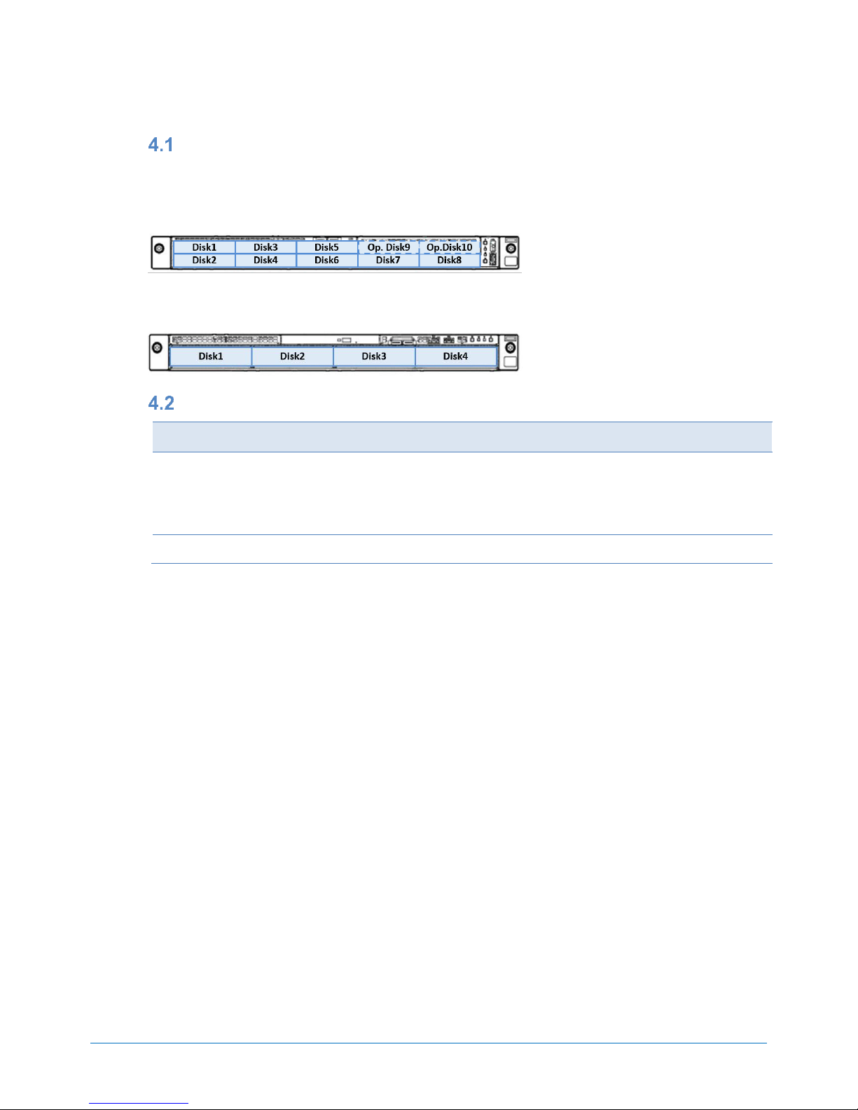
Front and Rear Views
Front View for 8x 2.5-inch Drive Model
Legend
A.
2.5-inch Drive Bays
F.
USB 3.0 Connector
B.
Pull-out tab
G.
LINK/ACT LED
C.
Optional Drive Bay
H.
UID Button LED
D.
Health LED
I.
iLO Service Connector
E.
Power On/standby button/LED
Front View for 4x 3.5-inch Drive Model
Legend
A.
3.5-inch Drive Bays
F.
UID Button LED
B.
Optional Drive Bay
G.
LINK/ACT LED
C.
Pull-out tab
H
Health LED
D.
iLO Service Connector
I
Power On/standby button/LED
E.
USB 3.0 Connector
Rear View
Legend
A.
PCIe slots (option)
F.
VGA connector
B.
PCIe slots (option)
G.
NIC ports 1-2 (1Gb)
C.
Flexible LOM (optional)
H.
UID LED
D.
USB 3.0 Connectors
I.
Serial Port Connector (optional)
E.
Management Port
J.
Power Supply
Page 28

SYSTEM CONFIGURATION GUIDE – NEC Express5800/R120h-1E
NEC Corporation Revision 2.0 – December 2017 28
Dimensions (mm)
Page 29

SYSTEM CONFIGURATION GUIDE – NEC Express5800/R120h-1E
NEC Corporation Revision 2.0 – December 2017 29
Server Management
The integrated server management controller provides superior remote control and system management features listed in the table
below.
Standard
Remote
Management
License
(Scale-out)
Remote
Management
License
(Advanced)
Authentication with Active Directory and LDAP
-
-
Two-factor and Kerberos authentication
-
-
Virtual media access via Integrated Remote Console (IRC)
-
-
Scripted virtual media access
-
-
Integrated Remote Console (IRC)
Pre-OS Only
Pre-OS Only
Global team collaboration for up to six consoles
-
-
Integrated Remote Console (IRC) recording and playback
-
-
Virtual Serial Port recording and playback
-
Text-based remote console via SSH
-
Email alert
-
Remote Syslog feature
Advanced power management
(power history graph, power capping)
-
BMC federation management
-
BMC detection for BMC federation
Remote serial console (Virtual Serial Port)
Server Health Summary
Restart BMC form web-based management console
Redfish™API
Agentless Management
Server Health monitoring
Web-based GUI
Virtual power buttons
SSH / SMASH Command-Line Protocol
(including serial console redirection)
IPMI / DCMI (including serial console redirection)
Page 30

SYSTEM CONFIGURATION GUIDE – NEC Express5800/R120h-1E
NEC Corporation Revision 2.0 – December 2017 30
OS Support Matrix for PCI Cards and Embedded Controllers
Part number
Product Name
WS 20
16
WS 2012 R2 RHEL
7
ESXi
6.5
ESXi
6.0
-
Embedded SATA non-RAID Controller
-
Embedded SATA RAID Controller
- - - - Embedded 1Gb NIC
N8103-192
RAID Controller (RAID 0/1)
N8103-193
RAID Controller (2GB, RAID 0/1/5/6)
N8103-195
RAID Controller (4GB, RAID 0/1)
N8103-201
RAID Controller (2GB, RAID 0/1/5/6)
N8103-196
RAID Controller (4GB, RAID 0/1/5/6)
N8103-197
SAS Controller
-
N8104-193
Dual Port 1000BASE-T LOM Card
-
N8104-194
Dual Port 10GBASE SFP+ LOM Card
-
N8104-195
Dual Port 10GBASE-T LOM Card
-
N8104-171
Quad Port 1000BASE-T LOM Card
N8104-172
Quad Port 1000BASE-T LOM Card
-
N8104-173
Quad Port 10GBASE-T LOM Card
N8104-175
Dual Port 10GBASE-T LOM Card
N8104-176
Quad Port 10BASE SFP+ LOM Card
N8104-177
Dual Port 25GBASE SFP+ LOM Card
-
-
N8104-178
Dual Port 1000BASE-T Adapter
N8104-179
Quad Port 1000BASE-T Adapter
N8104-180
Dual Port 1000BASE-T Adapter
-
N8104-181
Quad Port 1000BASE-T Adapter
-
N8104-182
Dual Port 10GBASE-T Adapter
N8104-183
Dual Port 10GBASE-T Adapter
N8104-184
Dual Port 10GBASE-T Adapter
N8104-185
Dual 10GBASE SFP+ Adapter
N8104-186
Dual 10GBASE SFP+ Adapter
N8104-188
Quad Port 25GBASE QSFP28 Adapter
-
-
N8104-187
Dual Port 25GBASE SFP28 Adapter
-
-
N8190-165
Fibre Channel Controller (1ch)
-
-
-
N8190-166
Fibre Channel Controller (2ch)
-
-
-
N8190-171
Fibre Channel Controller (1ch)
-
-
N8190-172
Fibre Channel Controller (2ch)
-
-
N8190-163
Fibre Channel Controller (1ch)
N8190-164
Fibre Channel Controller (2ch)
Page 31

SYSTEM CONFIGURATION GUIDE – NEC Express5800/R120h-1E
NEC Corporation Revision 2.0 – December 2017 31
Supported PCI Cards and Installable Slots
Part Number
Product Name
RAID
LOM
SLOT1
(ALOM)
SLOT1
(PCI)
SLOT2
SLOT3
N8103-192
RAID Controller (RAID 0/1)
1 - - - - N8103-193
RAID Controller (2GB, RAID 0/1/5/6)
1 - - - - N8103-195
RAID Controller (4GB, RAID 0/1)
- - 2 1 3 N8103-201
RAID Controller (2GB, RAID 0/1/5/6)
- - 2 1 3 N8103-196
RAID Controller (4GB, RAID 0/1/5/6)
- - 2 1 3 N8103-197
SAS Controller
- - 2 1 3 N8104-193
Dual Port 1000BASE-T LOM Card
- 1 - - - - N8104-194
Dual Port 10GBASE SFP+ LOM Card
- 1 - - - - N8104-195
Dual Port 10GBASE-T LOM Card
- 1 - - - - N8104-171
Quad Port 1000BASE-T LOM Card
- 1 - - - N8104-172
Quad Port 1000BASE-T LOM Card
- 1 - - - N8104-173
Quad Port 10GBASE-T LOM Card
- 1 - - - N8104-175
Dual Port 10GBASE-T LOM Card
- 1 - - - N8104-176
Quad Port 10BASE SFP+ LOM Card
- 1 - -
-
N8104-177
Dual Port 25GBASE SFP+ LOM Card
- 1 - -
-
N8104-178
Dual Port 1000BASE-T Adapter
- - 2 1 3 N8104-179
Quad Port 1000BASE-T Adapter
- - 2 1 3 N8104-180
Dual Port 1000BASE-T Adapter
- - 2 1 3 N8104-181
Quad Port 1000BASE-T Adapter
- - 2 1 3 N8104-182
Dual Port 10GBASE-T Adapter
- - 2 1 3 N8104-183
Dual Port 10GBASE-T Adapter
- - 2 1 3 N8104-184
Dual Port 10GBASE-T Adapter
- - 2 1 3 N8104-185
Dual 10GBASE SFP+ Adapter
- - 2 1 3 N8104-186
Dual 10GBASE SFP+ Adapter
- - 2 1 3 N8104-187
Dual Port 25GBASE SFP28 Adapter
- - 2 1 3 N8104-188
Quad Port 25GBASE QSFP28 Adapter
- - 1 - 2 N8190-165
Fibre Channel Controller (1ch)
- - 2 1 3 N8190-166
Fibre Channel Controller (2ch)
- - 2 1 3 N8190-171
Fibre Channel Controller (1ch)
- - 2 1 3 N8190-172
Fibre Channel Controller (2ch)
- - 2 1 3 N8190-163
Fibre Channel Controller (1ch)
- - 2 1 3 N8190-164
Fibre Channel Controller (2ch)
- - 2 1
3
NOTE:
PCI slot #3 is not available when a RAID controller is installed into the RAID slot.
To install N8104-188 Quad 25GBASE-QSFP28 Adapter, the bus width of the PCI slot for this adapter must be x16.
Expansion Slots
Slot Name
Standard
Bus
Width
Connector
Width
Height
Length
Processor
Dedicated
Slots
FLOM
- - - - - - RAID
PCIe 3.0
x8
x8 - -
CPU1
1st Riser Card
(Optional)
Slot 1 (PCI)
PCIe 3.0
x16
x16
Full-height
Up to 168 mm
CPU1
Slot 2
PCIe 3.0
X8
x8
Low Profile
Up to 168 mm
CPU1
1st Riser Card
(Optional)
Slot 1 (PCIe SSD)
PCIe 3.0
x8 - - - CPU1
Slot 1 (ALOM)
PCIe 3.0
x8
x8 - -
CPU1
Slot 2
PCIe 3.0
x16
x16
Low Profile
Up to 168 mm
CPU1
2rd Riser Card
(Optional)
Slot 3
PCIe 3.0
x16
x16
Low Profile
Up to 168 mm
CPU2
Page 32

SYSTEM CONFIGURATION GUIDE – NEC Express5800/R120h-1E
NEC Corporation Revision 2.0 – December 2017 32
Supported Tape and Removal Disk Backup Drive List
See the following table for supported tape and removal disk backup drives. An optional tape drive enclosure is needed to connect
the backup drives to the server.
Category
Product Name / Description
Part Number
LTO
Internal LTO (SAS)
LTO5, Half height, Native capacity 1.5 TB
N8151-141
Internal LTO (SAS)
LTO6, Half height, Native capacity 2.5 TB
N8151-142
Internal LTO (SAS)
LTO7, Half height, Native capacity 6 TB
N8151-143
RDX
Internal RDX (USB)
N8151-139
Boot Mode Setting
The server supports Legacy mode and UEFI mode (default) as an OS Boot Mode. See the table below for the Boot Mode and
X2APIC setting for each Operating System. As the default settings at the factory, UEFI mode is set as OS Boot mode and X2APIC
is enabled. Refer to the User’s Guide and change the settings before installing an Operating System requiring Legacy Mode.
Operating System
Supported Boot Mode
Supported X2APIC Setting
Windows Server 2012 R2
UEFI
Enabled
Windows Server 2016
UEFI
Enabled
VMware ESXi 6.0 Update3
UEFI
Enabled
VMware ESXi 6.5 Update1
UEFI
Enabled
Page 33

SYSTEM CONFIGURATION GUIDE – NEC Express5800/R120h-1E
NEC Corporation Revision 2.0 – December 2017 33
Guideline of Maximum Power Consumption
See the following table for the guideline of the maximum power consumption based on the TDP and Input voltage. The actual
maximum power consumption differs depend on the type of processor while the TDP of processor is the same.
100VAC Input
CPU TDP
8x 2.5-inch
4x 3.5-inch
85 Watt
691W / 692VA
643W / 644VA
105 Watt
757W / 758VA
708W / 709VA
115 Watt
764W / 765VA
715W / 716VA
125 Watt
818W / 819VA
769W / 770VA
130 Watt
818W / 819VA
769W / 770VA
140 Watt
892W / 893VA
843W / 843VA
150 Watt
895W / 896VA
845W / 846VA
Page 34

SYSTEM CONFIGURATION GUIDE – NEC Express5800/R120h-1E
NEC Corporation Revision 2.0 – December 2017 34
Copyright Notice and Liability Disclaimer
The information contained herein is subject to change without notice.
Microsoft and Windows Server are either registered trademarks or trademarks of Microsoft Corporation in the United States and/or
other countries
Intel and Xeon are registered trademarks or trademarks of Intel Corporation or its subsidiaries in the United States and other
countries.
Linux is a trademark of Linus Torvalds.
Red Hat is a registered trademark of Red Hat, Inc. in the U.S.
All other products, brands, or trade names used in this document are trademarks or registered trademarks of their respective
holders.
NEC shall not be liable for technical or editorial errors or omissions contained herein.
For hard drive capacity measurements, 1 GB = 1 billion bytes. Actual formatted capacity is less.
Page 35

SYSTEM CONFIGURATION GUIDE – NEC Express5800/R120h-1E
NEC Corporation Revision 2.0 – December 2017 35
Revision History
Revision
Date
Description
2.0
December 22, 2017
New products added:
● 400GB Hot Plug 2.5-inch SAS SSD / N8150-748
● 800GB Hot Plug 2.5-inch SAS SSD / N8150-749
● 400GB Hot Plug 2.5-inch SAS SSD / N8150-750
● 800GB Hot Plug 2.5-inch SAS SSD / N8150-751
● 480GB Hot Plug 2.5-inch SAS SSD / N8150-752
● 960GB Hot Plug 2.5-inch SAS SSD / N8150-753
● Dual Port 25GBASE SFP28 Adapter / N8104-187
● Dual Port 25GBASE SFP+ LOM Card / N8104-177
● SFP+ Module (10G-SR) / N8104-189
● SFP28 Module(25G-SR) / N8104-190
● QSFP28 Module(100G-SR4) / N8104-191
● SAS Controller / N8103-184
● 500W Non-hot Plug Power Supply / N8181-168
● 500W Hot Plug Power Supply / N8181-159
Others:
● Updated the table of the Available Power Supplies
1.0
November 22, 2017
Initial release
 Loading...