

Page 1

NEC Express Server
Express5800 Series
Express5800/R120g-2E
EXP330A
User’s Guide
Chapter 1 General Description
Chapter 2 Preparations
Chapter 3 Setup
Chapter 4 Appendix
10.115.02-101.01
April 2016
© NEC Corporation 2016
Page 2
Manuals
Express5800/R120g-2E User's Guide
2
Manuals
Manuals for this product are provided as booklets ( ) and electronic manuals (
PDF
) in EXPRESSBUILDER.
Safety Precautions and
Regulatory Notices
Describes points of caution to ensure the safe use of this server.
Read these cautions before using this server.
Getting Started
Describes how to use this server, from unpacking to operations.
See this guide first and read the outline of this product.
PDF
User’s Guide
Chapter 1: General Description Overviews, names, and functions of the server’s parts
Chapter 2: Preparations Installation of additional options, connection of peripheral devices,
and suitable location for this server
Chapter 3: Setup System BIOS configurations and summary of EXPRESSBUILDER
Chapter 4: Appendix Specifications and other information
PDF
Installation Guide (Windows)
Chapter 1: Installing Windows Installation of Windows and drivers, and precautions for installation
Chapter 2: Installing Bundled
Software
Installation of NEC ESMPRO, Universal RAID Utility, and other
bundled software
PDF
Maintenance Guide
Chapter 1: Maintenance Server maintenance and troubleshooting
Chapter 2: Useful Features The detail of system BIOS settings, RAID Configuration Utility, and
EXPRESSBUILDER
Chapter 3: Appendix Error messages and Windows Event Logs
PDF
Other manuals
The detail of NEC ESMPRO, Universal RAID Utility, and other features
EXPRESSBUILDER
Page 3

Contents
Express5800/R120g-2E User's Guide
3
Contents
Manuals ................................................................................................................................................................. 2
Contents ................................................................................................................................................................ 3
Conventions Used in This Document .................................................................................................................... 6
Signs and symbols for safety ........................................................................................................................ 6
Notations used in the text .............................................................................................................................. 7
Optical disk drive ........................................................................................................................................... 7
Hard disk drive .............................................................................................................................................. 7
Removable media ......................................................................................................................................... 7
Abbreviations of Operating Systems (Windows) ........................................................................................... 8
POST ........................................................................................................................................................... 8
BMC ........................................................................................................................................................... 8
Trademarks ........................................................................................................................................................... 9
License Agreement Notice ................................................................................................................................... 10
Warnings and Additions to This Document .......................................................................................................... 13
Latest editions ............................................................................................................................................. 13
Safety notes ................................................................................................................................................ 14
Handling precautions .................................................................................................................................. 15
Chapter 1 General Description ......................................................................................................................... 17
1.
Introduction ................................................................................................................................................. 18
2.
Accessories ................................................................................................................................................. 19
3.
Features ...................................................................................................................................................... 20
3.1
Firmware and Software Version Management ................................................................................. 23
4.
Names and Functions of Parts .................................................................................................................... 24
4.1
Front View (With Front Bezel) .......................................................................................................... 24
4.2
Front View (Without Front Bezel) ..................................................................................................... 26
4.3
Rear View ........................................................................................................................................ 28
4.4
External View ................................................................................................................................... 29
4.5
Internal View .................................................................................................................................... 30
4.6
Motherboard .................................................................................................................................... 31
4.7
Status Indicators .............................................................................................................................. 33
4.7.1
POWER LED ( ) ......................................................................................................... 33
4.7.2
STATUS LED 1, 2 ( ) ..................................................................................................... 33
4.7.3
LINK/ACT LED ( 1, 2, M) ................................................................................... 35
4.7.4
Optical Disk Drive Access LED (option) ............................................................................. 35
4.7.5
UID LED (ID) ...................................................................................................................... 35
4.7.6
Power Capping LED .......................................................................................................... 35
4.7.7
LED on a hard disk drive ................................................................................................... 36
4.7.8
LEDs for LAN connectors .................................................................................................. 37
4.7.9
AC POWER LED on Power Unit ........................................................................................ 38
4.7.10
Global HDD LED1,2(1- -2) .............................................................................................. 39
Page 4

Contents
Express5800/R120g-2E User's Guide
4
Chapter 2 Preparations .................................................................................................................................... 40
1.
Installing Internal Optional Devices ................................................................................................................. 41
1.1
Safety Precautions ............................................................................................................................... 41
1.2
Anti-static Measures ............................................................................................................................. 42
1.3
Overview of Installation and Removal .................................................................................................. 43
1.4
Confirming Servers (UID Switch) ......................................................................................................... 45
1.5
Removing Front Bezel .......................................................................................................................... 46
1.6
Removing Top Cover ............................................................................................................................ 48
1.7
Removing Support Bar ......................................................................................................................... 49
1.8
Removing Air Duct ................................................................................................................................ 50
1.9
TPM Kit ................................................................................................................................................ 51
1.9.1
Installation ............................................................................................................................... 51
1.10
Processor (CPU) ................................................................................................................................ 52
1.10.1
Maximum number of processor cores supported by this server ............................................. 52
1.10.2
Installation .............................................................................................................................. 53
1.10.3
Replacement / Removal ......................................................................................................... 57
1.11
DIMM ................................................................................................................................................. 58
1.11.1
Maximum supported memory size ......................................................................................... 59
1.11.2
Memory clock ......................................................................................................................... 60
1.11.3
Memory RAS feature ............................................................................................................. 61
1.11.4
DIMM installation order .......................................................................................................... 62
1.11.5
Installation .............................................................................................................................. 64
1.11.6
Removal / Replacement ......................................................................................................... 65
1.11.7
Cluster On Die and Early Snoop features .............................................................................. 66
1.11.8
Using Memory RAS feature ................................................................................................... 69
1.12
Flash Backup Unit for RAID Controller ............................................................................................... 79
1.12.1
Handling precautions ............................................................................................................. 79
1.12.2
Installation .............................................................................................................................. 79
1.12.3
Removal ................................................................................................................................. 82
1.13
Additional / Redundant Fan Unit ........................................................................................................ 83
1.13.1
Installation .............................................................................................................................. 84
1.13.2
Replacement / Removal ......................................................................................................... 84
1.14
Backup Device ................................................................................................................................... 85
1.14.1
Installation .............................................................................................................................. 85
1.14.2
Removal ................................................................................................................................. 87
1.15
PCI Card ............................................................................................................................................ 88
1.15.1
Notes ..................................................................................................................................... 88
1.15.2
Supported PCI cards and available slots ............................................................................... 89
1.15.3
Installation .............................................................................................................................. 91
1.15.4
Removal ................................................................................................................................. 92
1.15.5
Installing RAID Controller ....................................................................................................... 92
1.16
Additional 2.5-inch HDD Cage ........................................................................................................... 93
1.16.1
Installation .............................................................................................................................. 93
1.16.2
Removal ................................................................................................................................. 99
1.17
Additional 2.5-inch HDD Cage (Rear) .............................................................................................. 100
1.17.1
Installation ............................................................................................................................ 100
1.17.2
Removal ............................................................................................................................... 104
1.18
2.5-inch PCIe SSD Installation Kit .................................................................................................... 105
1.18.1
Installation ............................................................................................................................ 105
1.18.2
Removal ............................................................................................................................... 116
1.19
Optical Disk Drive ............................................................................................................................ 117
1.19.1
Installation ............................................................................................................................ 117
1.19.2
Removal ............................................................................................................................... 118
1.20
Use of Internal Hard Disk Drives in the RAID System ...................................................................... 119
1.20.1
Connecting cables ............................................................................................................... 120
1.20.2
Notes on Building RAID System .......................................................................................... 128
1.21
Installing Air Duct ............................................................................................................................. 129
1.22
Installing Support Bar ....................................................................................................................... 129
1.23
Installing Top Cover ......................................................................................................................... 129
Page 5

Contents
Express5800/R120g-2E User's Guide
5
1.24
2.5-inch Hard Disk Drive .................................................................................................................. 130
1.24.1
Installation ............................................................................................................................ 130
1.24.2
Removal ............................................................................................................................... 132
1.24.3
Replacing a hard disk drive in the RAID System (Auto Rebuild) .......................................... 132
1.25
3.5-inch Hard Disk Drive .................................................................................................................. 133
1.25.1
Installation ............................................................................................................................ 133
1.25.2
Removal ............................................................................................................................... 135
1.25.3
Replacing a hard disk drive in the RAID System (Auto Rebuild) .......................................... 135
1.26
Power Supply Unit ........................................................................................................................... 136
1.26.1
Cold Redundant Feature ...................................................................................................... 136
1.26.2
Installation ............................................................................................................................ 137
1.26.3
Replacing a failed power supply unit.................................................................................... 138
1.27
Installing Front Bezel ....................................................................................................................... 139
2.
Installation and Connection ........................................................................................................................... 140
2.1
Installation .......................................................................................................................................... 140
2.1.1
Installing Rack ....................................................................................................................... 140
2.1.2
Installing the server to the rack or removing it from the rack ................................................. 142
2.2
Connection ......................................................................................................................................... 149
2.2.1
Connecting to Uninterruptible Power Supply (UPS) .............................................................. 152
Chapter 3 Setup ............................................................................................................................................. 153
1.
Turning on the Server .................................................................................................................................... 154
1.1
POST ................................................................................................................................................. 155
1.1.1
POST sequence .................................................................................................................... 155
1.1.2
POST error messages ........................................................................................................... 157
2.
BIOS Setup Utility (SETUP) .......................................................................................................................... 158
2.1
Overview ............................................................................................................................................ 158
2.2
Starting SETUP Utility ........................................................................................................................ 158
2.3
Description on On-Screen Items and Key Usage ............................................................................... 159
2.4
Cases that Require Configuration ...................................................................................................... 161
2.5
BIOS setting by network ..................................................................................................................... 163
2.5.1
Overview ................................................................................................................................ 163
2.5.2
Backing up the BIOS setting .................................................................................................. 164
2.5.3
Restoring the BIOS setting .................................................................................................... 164
2.5.4
Notes ..................................................................................................................................... 166
3.
EXPRESSSCOPE Engine 3 ......................................................................................................................... 167
3.1
Overview ............................................................................................................................................ 167
3.2
EXPRESSSCOPE Engine 3 Network Configuration .......................................................................... 167
4.
EXPRESSBUILDER ...................................................................................................................................... 169
4.1
Features of EXPRESSBUILDER ........................................................................................................ 169
4.2
Usage of EXPRESSBUILDER ........................................................................................................... 169
5.
Installing Software Components .................................................................................................................... 170
6.
Turning Off the Server ................................................................................................................................... 171
Chapter 4 Appendix ....................................................................................................................................... 172
1.
Specifications ................................................................................................................................................ 173
2.
Interrupt Lines ............................................................................................................................................... 179
3.
Glossary ........................................................................................................................................................ 180
4.
Revision Record ............................................................................................................................................ 181
Page 6
Conventions Used in This Document
Express5800/R120g-2E User's Guide
6
Conventions Used in This Document
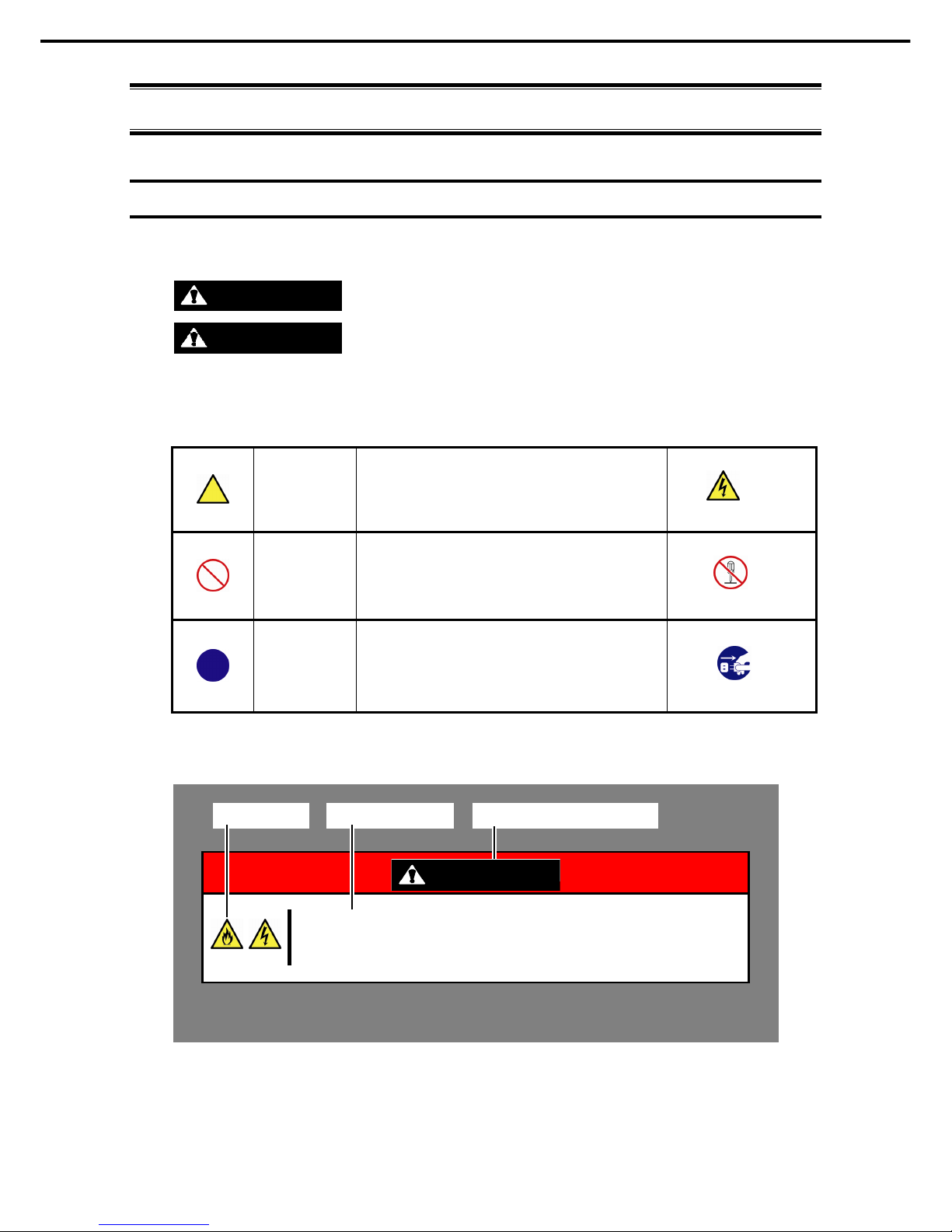
Signs and symbols for safety
WARNING and CAUTION are used in this guide as following meaning.
WARNING
Indicates there is a risk of death or serious personal injury
CAUTION
Indicates there is a risk of burns, other personal injury, or property damage
Precautions and notices against hazards are presented with one of the following three symbols. The individual
symbols are defined as follows:
Attention This symbol indicates the presence of a hazard if
the instruction is ignored.
An image in the symbol illustrates the hazard type.
Prohibited
Action
This symbol indicates prohibited actions. An image
in the symbol illustrates a particular prohibited
action.
Mandatory
Action
This symbol indicates mandatory actions. An
image in the symbol illustrates a mandatory action
to avoid a particular hazard.
(Example in this guide)
WARNING
Use only the specified outlet
Use a grounded outlet with the specified voltage. Use of an improper power source
may cause a fire or a power leak.
(Do not disassemble)
(Electric shock risk)
(Example)
(Example)
(Example)
(Disconnect a plug)
Symbol to draw
attention
Description of a warning
Term indicating a degree of danger
Page 7

Conventions Used in This Document
Express5800/R120g-2E User's Guide
7
Notations used in the text
In addition to safety-related symbols urging caution, three other types of notations are used in this document.
These notations have the following meanings.
Important Indicates critical items that must be followed when handling hardware or operating software. If
the procedures described are not followed, server failure, data loss, and other serious
malfunctions could occur.
Note Indicates items that must be confirmed when handling hardware or operating software.
Tips Indicates information that is helpful to keep in mind when using this server.
Optical disk drive
This server is equipped with one of the following drives. These drives are referred to as optical disk drive (ODD)
in this document.
• DVD-ROM drive
• DVD Super MULTI drive
Hard disk drive
Unless otherwise stated, hard disk drive (HDD) described in this document refers to both of the following.
• Hard disk drive (HDD)
• Solid state drive (SSD)
Removable media
Unless otherwise stated, removable media described in this document refers to both of the following.
• USB flash drive
• Flash FDD
Page 8

Conventions Used in This Document
Express5800/R120g-2E User's Guide
8
Abbreviations of Operating Systems (Windows)
Windows Operating Systems are referred to as follows.
See Chapter 1 (1.2 Supported Windows OS) in Installation Guide (Windows) for detailed information.
Notations in this document Official names of Windows
Windows Server 2012 R2
Windows Server 2012 R2 Standard
Windows Server 2012 R2 Datacenter
Windows Server 2012
Windows Server 2012 Standard
Windows Server 2012 Datacenter
Windows Server 2008 R2
Windows Server 2008 R2 Standard
Windows Server 2008 R2 Enterprise
POST
POST described in this document refers to the following.
• Power On Self-Test
BMC
BMC described in this document refers to the following.
• Baseboard Management Controller
Page 9

Trademarks
Express5800/R120g-2E User's Guide
9
Trademarks
EXPRESSSCOPE and ExpressUpdate are registered trademark of NEC Corporation.
Microsoft, Windows, and Windows Server are registered trademarks or trademarks of Microsoft Corporation in the United States and
other countries.
Intel, Pentium, and Xeon are registered trademarks of Intel Corporation of the United States.
Avago, LSI, and the LSI & Design logo are trademarks or registered trademarks of Avago Technologies in the United States and/or
other countries.
PCI Express is a trademark of Peripheral Component Interconnect Special Interest Group.
InfiniBand is a trademark or service mark of InfiniBand Trade Association.
Mellanox, and its logo, and Connect-X, Switch-X, MLNX-OS products are trademarks or registered trademarks of Mellanox
Technologies in Israel and other countries.
Qlogic is a trademark or registered trademark of QLogic Corporation.
Broadcom and NetXtreme are trademarks of Broadcom Corporation and (or) related organizations in the United States, EU and other
countries.
All other product, brand, or trade names used in this publication are the trademarks or registered trademarks of their respective
trademark owners.
Page 10

License Agreement Notice
Express5800/R120g-2E User's Guide
10
License Agreement Notice
Open source software of following license is included in the part of this product (system BIOS).
• EDK/EDKII
• UEFI Network Stack II and iSCSI
• Crypto package using WPA Supplicant
Open source software of following license is included in the part of this product (Off-line Tools).
• EDK/EDKII
EDK/EDKII
BSD License from Intel
Copyright (c) 2012, Intel Corporation
All rights reserved.
Copyright (c) 2004, Intel Corporation
All rights reserved.
Redistribution and use in source and binary forms, with or without modification, are permitted provided that the
following conditions are met:
・ Redistributions of source code must retain the above copyright notice, this list of conditions and the following
disclaimer.
・ Redistributions in binary form must reproduce the above copyright notice, this list of conditions and the
following disclaimer in the documentation and/or other materials provided with the distribution.
・ Neither the name of the Intel Corporation nor the names of its contributors may be used to endorse or
promote products derived from this software without specific prior written permission.
THIS SOFTWARE IS PROVIDED BY THE COPYRIGHT HOLDERS AND CONTRIBUTORS "AS IS" AND ANY
EXPRESS OR IMPLIED WARRANTIES, INCLUDING, BUT NOT LIMITED TO, THE IMPLIED WARRANTIES OF
MERCHANTABILITY AND FITNESS FOR A PARTICULAR PURPOSE ARE DISCLAIMED. IN NO EVENT
SHALL THE COPYRIGHT OWNER OR CONTRIBUTORS BE LIABLE FOR ANY DIRECT, INDIRECT,
INCIDENTAL, SPECIAL, EXEMPLARY, OR CONSEQUENTIAL DAMAGES (INCLUDING, BUT NOT LIMITED
TO, PROCUREMENT OF SUBSTITUTE GOODS OR SERVICES; LOSS OF USE, DATA, OR PROFITS; OR
BUSINESS INTERRUPTION) HOWEVER CAUSED AND ON ANY THEORY OF LIABILITY, WHETHER IN
CONTRACT, STRICT LIABILITY, OR TORT (INCLUDING NEGLIGENCE OR OTHERWISE) ARISING IN ANY
WAY OUT OF THE USE OF THIS SOFTWARE, EVEN IF ADVISED OF THE POSSIBILITY OF SUCH DAMAGE.
Page 11

License Agreement Notice
Express5800/R120g-2E User's Guide
11
UEFI NETWORK STACK II and iSCSI
OpenSSL License
-------
Copyright (c) 1998-2011 The OpenSSL Project. All rights reserved.
Redistribution and use in source and binary forms, with or without modification, are permitted provided that the
following conditions are met:
1. Redistributions of source code must retain the above copyright notice, this list of conditions and the
following disclaimer.
2. Redistributions in binary form must reproduce the above copyright notice, this list of conditions and the
following disclaimer in the documentation and/or other materials provided with the distribution.
3. All advertising materials mentioning features or use of this software must display the following
acknowledgment:
"This product includes software developed by the OpenSSL Project for use in the OpenSSL Toolkit.
(http://www.openssl.org/)"
4. The names "OpenSSL Toolkit" and "OpenSSL Project" must not be used to endorse or promote products
derived from this software without prior written permission. For written permission, please contact
openssl-core@openssl.org.
5. Products derived from this software may not be called "OpenSSL" nor may "OpenSSL" appear in their
names without prior written permission of the OpenSSL Project.
6. Redistributions of any form whatsoever must retain the following acknowledgment:
"This product includes software developed by the OpenSSL Project for use in the OpenSSL Toolkit
(http://www.openssl.org/)"
THIS SOFTWARE IS PROVIDED BY THE OpenSSL PROJECT ``AS IS'' AND ANY EXPRESSED OR IMPLIED
WARRANTIES, INCLUDING, BUT NOT LIMITED TO, THE IMPLIED WARRANTIES OF MERCHANTABILITY
AND FITNESS FOR A PARTICULAR PURPOSE ARE DISCLAIMED. IN NO EVENT SHALL THE OpenSSL
PROJECT OR ITS CONTRIBUTORS BE LIABLE FOR ANY DIRECT, INDIRECT, INCIDENTAL, SPECIAL,
EXEMPLARY, OR CONSEQUENTIAL DAMAGES (INCLUDING, BUT NOT LIMITED TO, PROCUREMENT OF
SUBSTITUTE GOODS OR SERVICES; LOSS OF USE, DATA, OR PROFITS; OR BUSINESS INTERRUPTION)
HOWEVER CAUSED AND ON ANY THEORY OF LIABILITY, WHETHER IN CONTRACT, STRICT LIABILITY,
OR TORT (INCLUDING NEGLIGENCE OR OTHERWISE) ARISING IN ANY WAY OUT OF THE USE OF THIS
SOFTWARE, EVEN IF ADVISED OF THE POSSIBILITY OF SUCH DAMAGE.
This product includes cryptographic software written by Eric Young (eay@cryptsoft.com).
This product includes software written by Tim Hudson (tjh@cryptsoft.com).
Page 12

License Agreement Notice
Express5800/R120g-2E User's Guide
12
CRYPTO PACKAGE USING WPA SUPPLICANT
WPA Supplicant
-------
Copyright (c) 2003-2012, Jouni Malinen <j@w1.fi> and contributors
All Rights Reserved.
This program is licensed under the BSD license (the one with advertisement clause removed).
If you are submitting changes to the project, please see CONTRIBUTIONS file for more instructions.
License
-------
This software may be distributed, used, and modified under the terms of
BSD license:
Redistribution and use in source and binary forms, with or without modification, are permitted provided that the
following conditions are met:
1. Redistributions of source code must retain the above copyright notice, this list of conditions and the
following disclaimer.
2. Redistributions in binary form must reproduce the above copyright notice, this list of conditions and the
following disclaimer in the documentation and/or other materials provided with the distribution.
3. Neither the name(s) of the above-listed copyright holder(s) nor the names of its contributors may be used to
endorse or promote products derived from this software without specific prior written permission.
THIS SOFTWARE IS PROVIDED BY THE COPYRIGHT HOLDERS AND CONTRIBUTORS "AS IS" AND ANY
EXPRESS OR IMPLIED WARRANTIES, INCLUDING, BUT NOT LIMITED TO, THE IMPLIED WARRANTIES OF
MERCHANTABILITY AND FITNESS FOR A PARTICULAR PURPOSE ARE DISCLAIMED. IN NO EVENT
SHALL THE COPYRIGHT OWNER OR CONTRIBUTORS BE LIABLE FOR ANY DIRECT, INDIRECT,
INCIDENTAL, SPECIAL, EXEMPLARY, OR CONSEQUENTIAL DAMAGES (INCLUDING, BUT NOTLIMITED
TO, PROCUREMENT OF SUBSTITUTE GOODS OR SERVICES; LOSS OF USE, DATA, OR PROFITS; OR
BUSINESS INTERRUPTION) HOWEVER CAUSED AND ON ANY THEORY OF LIABILITY, WHETHER IN
CONTRACT, STRICT LIABILITY, OR TORT (INCLUDING NEGLIGENCE OR OTHERWISE) ARISING IN ANY
WAY OUT OF THE USE OF THIS SOFTWARE, EVEN IF ADVISED OF THE POSSIBILITY OF SUCH DAMAGE.
Page 13

Warnings and Additions to This Document
Express5800/R120g-2E User's Guide
13
Warnings and Additions to This Document
1. Unauthorized reproduction of the contents of this document, in part or in its entirety, is prohibited.
2. This document is subject to change at any time without notice.
3. Do not make copies or alter the document content without permission from NEC Corporation.
4. If you have any concerns, or discover errors or omissions in this document, contact your sales
representative.
5. Regardless of article 4, NEC Corporation assumes no responsibility for effects resulting from your
operations.
6. The sample values used in this document are not actual values.
Keep this document for future use.
Latest editions
This document was created based on the information available at the time of its creation. The screen images,
messages, and procedures are subject to change without notice. Substitute as appropriate when content has
been modified.
The most recent version of User’s Guide, as well as other related documents, is also available for download
from the following website.
http://www.nec.com/
Page 14
Warnings and Additions to This Document
Express5800/R120g-2E User's Guide
14
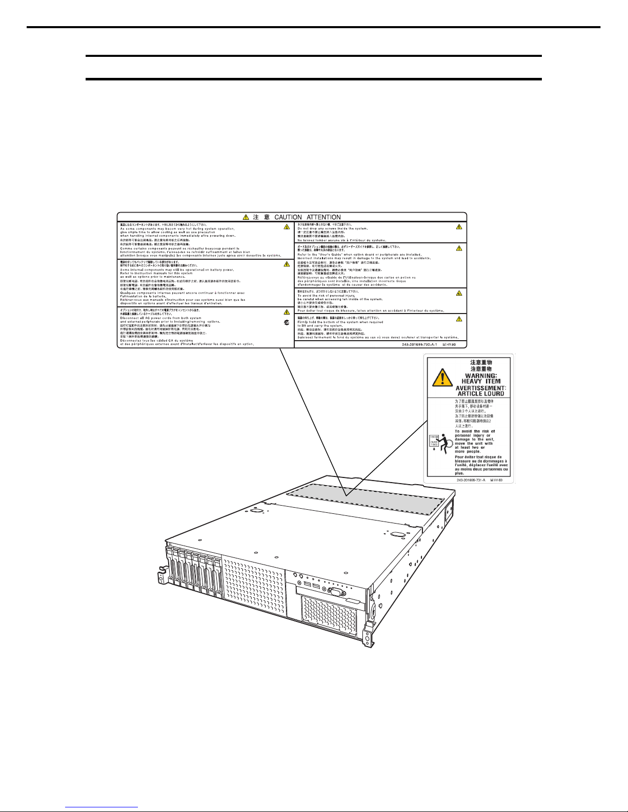
Safety notes
To use this server safely, read thoroughly "Safety Precautions and Regulatory Notices" that comes with your
server.
Warning labels are attached on or near the components with potential hazards. These labels are attached or
printed on the components.
Do not remove or black out these labels and keep them clean. If no labels are attached or printed on the server,
contact your sales representative.
Page 15

Warnings and Additions to This Document
Express5800/R120g-2E User's Guide
15
Handling precautions
Be sure to observe the following precautions for the proper functioning of the server. Ignoring the precautions
may cause server malfunction or failure.
• Do not use any cell phone or PHS and switch off them near the server. Electric waves from such
devices can cause server to malfunction.
• Install the server in an appropriate place. For details about the installation location, see Chapter 2
Preparations (2. Installation and Connection).
• Before connecting/removing cables to/from peripheral devices, make sure that the server is off and
unplug the power cord, if they are non plug-and-play devices.
• Connect the provided power cord to a 100/200 VAC outlet.
• Make sure that the access LED on the server is off before turning off the power or ejecting an optical
disk.
• Wait for at least 30 seconds before connecting power cord to power outlet after disconnecting it.
• If any Uninterruptible Power Supply (UPS) unit is connected, set it to wait for at least 30 seconds
before turning on the server after power off.
• Do not press the POWER switch to turn on the server before the STATUS LED1, 2 (amber) is unlit.
• Wait for at least 30 seconds before turning on the server after turning off the server.
• Turn off the server and unplug the power cord before moving it.
• Regularly clean the server to prevent various types of failure. See Chapter 1 Maintenance (2. Daily
Maintenance) in "Maintenance Guide" for details.
• Momentary voltage drop may occur due to lightning strike. To prevent this, use of UPS is
recommended.
• Any copy-protected CD that does not conform to standards is not supported.
• In the following cases, check and adjust the system clock before operation.
− After transportation
− After storage
− After a period of disuse in which storage conditions did not conform to those at which server operations
are guaranteed (Temperature: 5°C to 40°C [5°C to 45°C when an option is installed, subject to
restrictions on the configuration], Humidity: 20% to 80%)
• Check the system clock approximately once per month. Use of a time server (NTP server) is
recommended if high accuracy timing is required by the system.
• Observe the storage conditions (Temperature: −10°C to 55°C, Humidity: 20% to 80%, No
condensation of moisture) to store the server.
• Do not power off or reset the server, nor disconnect the power cord before POST completes.
• If this server, internal optional devices, and media set for the backup devices (tape cartridges) are
moved from a cold place to a warm place in a short time, condensation will occur and cause
malfunctions and failures when these are used in such state. To protect important stored data and
property, make sure to wait for a sufficient period to use the server and components in the operating
environment.
Reference: Time effective at avoiding condensation in winter (more than 10°C differences between the
room temperature and atmospheric temperature)
Disk devices: Approximately 2 to 3 hours Tape media: Approximately 1 day
• For optional devices, we recommend you use our NEC products. Even if they are successfully
installed or connected, installation of unsupported devices can cause the server to malfunction or
even failure. You will be charged to repair failure or damage caused by use of such products even
within warranty period.
Page 16
Warnings and Additions to This Document
Express5800/R120g-2E User's Guide
16
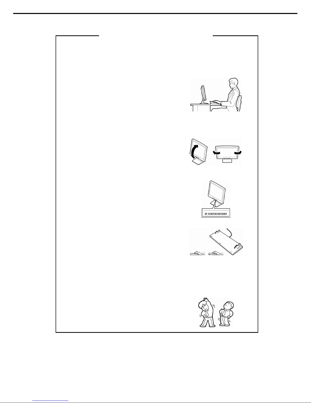
Using a computer extensively may affect different parts of your body. Here are tips you should follow while working on
a computer to minimize strain on your body.
Keep proper posture
The basic body position for using a computer is sitting straight with
your hands on the keyboard parallel with the floor, and your eyes
directed slightly downward toward the monitor. With the proper
posture described above, no unnecessary strain is applied on any
part of your body, in other words when your muscles are most
relaxed.
Working on the computer with bad posture such as hunching over or
being too close to the monitor could cause fatigue or deteriorated
eyesight.
Adjust the angle of your display
Most display units are designed for adjustment of the horizontal and
vertical angles. This adjustment is important to prevent the screen
from reflecting bright lights and to make the display contents easy to
see. Working without adjusting the display to a comfortable angle
makes it difficult for you to maintain a proper posture and you will
get tired easily. Adjust the viewing angle before use.
Adjust the brightness and contrast of the display
Display screens have functions to control brightness and contrast.
The most suitable brightness/contrast depends on age, individuals,
and environment, so adjust it to suit your preferences. A too bright
or too dark display is bad for your eyes.
Adjust the angle of keyboard
Some keyboards are ergonomically designed, which allow the angle
to be adjusted. Adjusting the angle of the keyboard is effective to
reduce tension on your shoulders, arms, and fingers.
Clean your equipment
Keeping your equipment clean is important not only for the appearance but also for functional and safety reasons. A
dusty monitor makes it difficult to see the display contents, so clean it regularly.
Take rest breaks
When you feel tired, take a break. Light exercise is also
recommended.
Tips for your health and safety
Page 17

Express5800/R120g-2E User's Guide
17
NEC Express5800 Series
Express5800/R120g-2E
General Description
This chapter introduces the features of this server and the name of each part.
1. Introduction
2. Accessories
Describes the accessories of the server.
3. Features
Describes the features of the server and server management.
4. Names and Functions of Parts
Describes the name of each part contained in this server.
Page 18

1. Introduction
Express5800/R120g-2E User's Guide
18
Chapter 1 General Description
1.
Introduction
Thank you for purchasing this NEC Express5800 Series product.
This high performance server is powered by the latest microprocessor "Intel® Xeon® processor".
NEC’s latest technology and architectures realize high-power and high-speed operation that cannot be matched
by existing servers.
The server is designed with consideration of not only reliability but also expandability, which enables you to use
it as a network server.
Read this document before using the server thoroughly to fully understand handling of Express5800 Series
Server and appreciate its functions to the maximum extent.
Page 19

2. Accessories
Express5800/R120g-2E User's Guide
19
Chapter 1 General Description
2.
Accessories
The carton box contains various accessories which are required for setup or maintenance. Make sure you
have them all for future use.
• Front Bezel
• Bezel Lock Key (attached to Front Bezel)
• Slide Rails
• Safety Precautions and Regulatory Notices
• Getting Started
• SAS cable (RAID controller is unmounted)
• Fixing screws for internal backup device
*1
*1 Only included with 16x2.5-inch drive models.
Make sure you have all accessories and inspect them. If an accessory is missing or damaged, contact your
sales representative.
Important
The chassis serial number plate and maintenance label is located on the
server. If the serial number does not match the number on the warranty, you
may not be guaranteed against failure even within the warranty period.
Contact your sales representative if they do not match.
Page 20

3. Features
Express5800/R120g-2E User's Guide
20
Chapter 1 General Description
3.
Features
The server has the following features:
High performance
• Intel Xeon processor
-N8101-1068F: Intel Xeon processor E5-2603v4 (1.70GHz 6Core)
-N8101-1069F: Intel Xeon processor E5-2609v4 (1.70GHz 8Core)
-N8101-1070F: Intel Xeon processor E5-2620v4 (2.10GHz 8Core)
-N8101-1071F: Intel Xeon processor E5-2623v4 (2.60GHz 4Core)
-N8101-1072F: Intel Xeon processor E5-2630v4 (2.20GHz 10Core)
-N8101-1073F: Intel Xeon processor E5-2650v4 (2.20GHz 12Core)
-N8101-1074F: Intel Xeon processor E5-2660v4 (2.00GHz 14Core)
-N8101-1075F: Intel Xeon processor E5-2690v4 (2.60GHz 14Core)
• Turbo Boost Technology feature *1
• Hyper Threading Technology feature *1
• High-speed memory access (DDR4 1600/1866/2133/2400 supported) *2
• High-speed disk access (SATA 6Gbps, 6Gbps, and SAS 12Gbps supported))
• High-speed 1000BASE-T/100BASE-TX/10BASE-T (2 ports) interface (1Gbps/100Mbps/10Mbps supported)
High reliability
• Processor throttle-ring feature
• Memory monitoring feature (error correction/error detection)
• Memory degeneracy feature (logical isolation of a failed device)
• Memory x4 SDDC feature
• Memory mirroring, memory LockStep (x8 SDDC), memory sparing features
• Memory throttle-ring feature
• Bus parity error detection
• Temperature detection
• Error detection
• Internal fan monitoring feature
• Internal voltage monitoring feature
• Power redundant feature (hot swapping supported)
• RAID system (Disk Array) (An option card is required.)
• Auto rebuild feature (hot swapping supported)
• BIOS password feature
• The security lock that comes with Front Bezel
• Redundant fan configuration
• Fan (hot swapping supported)
• HDD (hot swapping supported)
Page 21

3. Features
Express5800/R120g-2E User's Guide
21
Chapter 1 General Description
Management Utilities
• NEC ESMPRO
• ExpressUpdate
• Remote controlling feature (EXPRESSSCOPE Engine 3)
• RAID system management utility (Universal RAID Utility)
• Hard disk drive monitoring
• Power supply monitoring
Power saving and noiseless design
• Selection of power unit appropriate to environment, work load, and configuration
• Power consumption monitoring feature
• Power control feature
• 80 PLUS
®
Titanium certified high efficiency power supply *3
• Fan control appropriate to environment, work load, and configuration
• Silent sound design
• Enhanced Intel SpeedStep
®
Technology supported
• Cold redundant feature
Expandability
• PCI Express 3.0 (x16 lanes): 2 slot
• PCI Express 3.0 (x8 lanes): 2 slots *4
• PCI Express 2.0 (x4 lanes): 1 slot (x8 socket)
• Large capacity memory of up to 512 GB *5
• Can upgrade to multi-processor system with up to two processors
• Expansion Bay (for hard disk drives):
– 16x 2.5-inch Drive Model: 2.5-inch drive bay 16 slots *6
– 26x 2.5-inch Drive Model: 2.5-inch drive bay 26 slots *7
– 3.5-inch Drive Model: 3.5-inch drive bay 12 slots , 2.5-inch drive bay: 2 slots *8
• Optical disk drive bay provided as standard *9
• Expansion Bay (for backup unit) provided as standard *9
• USB3.0 interface (Front: 2 ports, rear: 2 ports, internal: 1 port)
• USB2.0 interface (Rear: 2 ports, internal: 1 port)
• Two LAN ports
• Management LAN port (1 port)
Ready to use
• No cable connection is required to install a hard disk drive, additional power supply unit, and redundant fan
unit (hot swap supported).
• Slide rails for each installation
Page 22

3. Features
Express5800/R120g-2E User's Guide
22
Chapter 1 General Description
Many built-in Features
• Redundant power supply system supported (valid when optional power supply unit is installed)
• El Torito Bootable CD-ROM (no emulation mode) format supported
• Software power-off
• Remote power-on feature
• AC-Link feature
• Remote console feature
• Power switch mask
• Connector for display unit provided on front panel*9
• Baseboard Management Controller (BMC) conforming to IPMI v2.0
• Secure boot supported
Self-diagnosis
• Power On Self-Test (POST)
• Test and Diagnosis (T&D) utility
Easy setup
• EXPRESSBUILDER (setup utility)
• BIOS Setup utility (SETUP)
Maintenance features
• Off-line Tools
• Memory dump feature using DUMP Switch
• Feature to backup and restore BIOS/BMC settings using EXPRESSSCOPE Profile Key
*1: Unsupported on Xeon processor E5-2603 v4, E5-2609 v4 embedded models.
*2: Processor core speed depends on processor type, number and type of DIMMs installed.
*3: Requires N8181-118F power unit. Power supply unit N8181-121F/122F/123F is compliant to 80 Plus
Platinum.
*4: In 2-CPU configuration. One slot in 1-CPU configuration.
*5: In 2-CPU configuration. Up to 256 GB in 1-CPU configuration.
*6: When an N8154-74 2.5-inch HDD cage is installed. A 2.5-inch drive bay with 8 slots is provided in
standard configuration.
*7: When an N8154-75 2.5-inch HDD cage and an N8154-76 2.5-inch HDD cage (rear) are installed.
A 2.5-inch drive bay with 16 slots is provided in standard configuration.
*8: When an N8154-76 2.5-inch HDD cage (rear) is installed. A 3.5-inch drive bay with 12 slots is provided in
standard configuration.
*9: Provided only for 16x 2.5-inch drive model.
Page 23

3. Features
Express5800/R120g-2E User's Guide
23
Chapter 1 General Description
3.1
Firmware and Software Version Management
Use of NEC ESMPRO Manager, ExpressUpdate Agent, and EXPRESSSCOPE Engine 3 allows you to
manage versions of firmware and software as well as update them by applying update packages.
This feature automatically updates modules without stopping the system just by specifying the updating
packages from NEC ESMPRO Manager.
Page 24
4. Names and Functions of Parts
Express5800/R120g-2E User's Guide
24
Chapter 1 General Description
4.
Names and Functions of Parts
This section describes the names of the server parts.
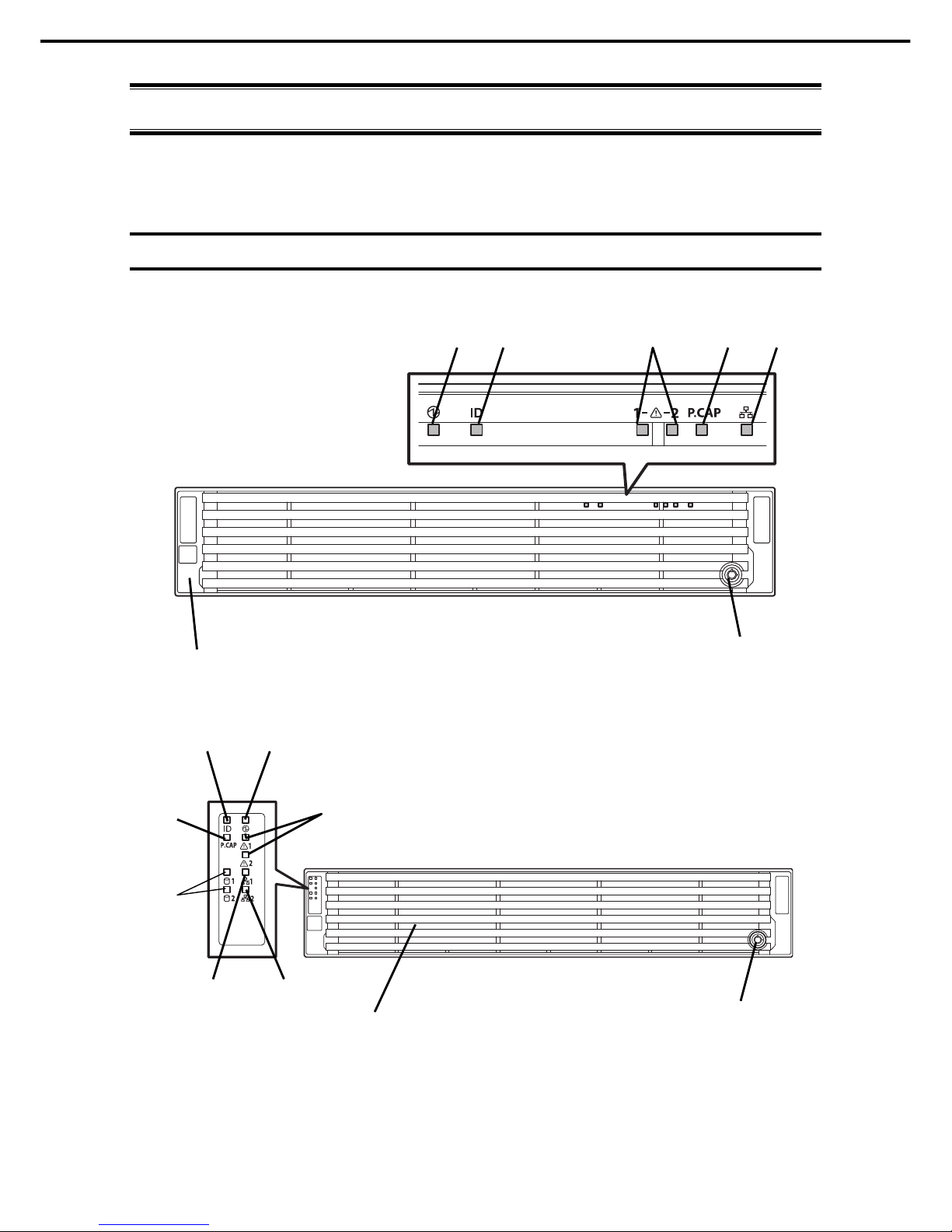
4.1
Front View (With Front Bezel)
16x 2.5-inch Drive Model
26x 2.5-inch Drive Model / 3.5-inch Drive Model
(1)
(2)
(3)-1
(4)
(5)
(6) (7)
(3)-2
(8)
(1)
(2)
(3) (4) (5) (6) (7)
Page 25

4. Names and Functions of Parts
Express5800/R120g-2E User's Guide
25
Chapter 1 General Description
(1) Front Bezel
A cover to protect the front of the server. This cover can be
locked with the provided Bezel Lock Key.
(2) Key Slot
A slot for Bezel Lock Key that is used to lock Front Bezel.
(3) LINK/ACT LED
LEDs for showing the status of accessing to the network.
(See page 35)
(3)-1: LAN1 connector
(3)-2: LAN2 connector
(4) Power Capping LED
An LED for showing the power capping status of the server.
(5) STATUS LED 1, 2
An LED for showing the server status.
(See page 33)
(6) Unit ID (UID) LED
An LED for maintaining the server. This LED turns on when
UID Switch is pressed. Commands from the software also
cause it to turn on or flash.
(See page 35)
(7) POWER LED
An LED for showing the power status of server.
(See page 33)
(8) Global HDD LED
LEDs for showing the hard disk drive status.
(See page 39)
Page 26
4. Names and Functions of Parts
Express5800/R120g-2E User's Guide
26
Chapter 1 General Description
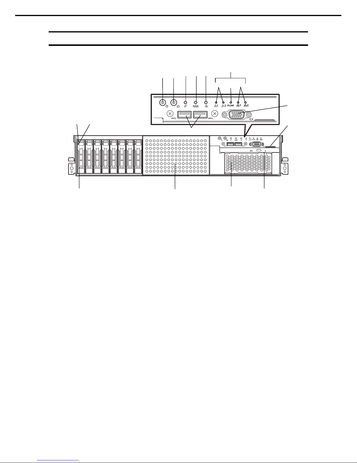
4.2
Front View (Without Front Bezel)
16x 2.5-inch Drive Model
(9) DISK LED
LEDs for showing the hard disk drive status.
The LED provided for each HDD.
(See page 36)
(10) 2.5-inch Hard Disk Drive Bay
Bays for installing HDDs.
(11) USB Connectors (front)
Connectors for connecting USB interface devices.
(12) RESET Switch
A switch for resetting the server.
(13) DUMP Switch (NMI)
A switch for collecting the memory dump.
(14) BMC RESET Switch
A switch for resetting BMC of this server. Use the switch
only when there is a problem with EXPRESSSCOPE
Engine 3 (BMC).
To use this switch, press it at least five seconds.
(15) POWER Switch/LED
A switch for turning on/off the server. Press once to turn on
the server. POWER LED lights when it is on. Press it again
to turn off the server. Hold down the switch for four seconds
or more to forcibly turn off the server.
(See page 33)
(16) Unit ID (UID) Switch/LED
A switch for turning on/off UID LED.
Pressing the switch once turns on UID LED and pressing
again turns off the LED.
Commands from the software also cause it to turn on or
flash.
(See page 35)
(17) Display Connector *1
A connector for connecting a display. This connector
cannot be used with the display connector on rear panel at
the same time.
(18) Pull-out Tab
A tab for showing the model number and serial number of
the server.
(19) 2.5-inch Additional HDD Cage Bay
A bay for installing 2.5-inch Additional HDD cage.
(20) Expansion Bay (for file backup unit)
A bay for installing an optional RDX drive.
(21) Optical Disk Drive Bay
A bay for installing an optical disk drive.
Either of the following drive can be installed.
– DVD-ROM drive
– DVD SuperMULTI drive
*1 The tray of optical disk drive cannot open depending on the
connector of display cable. In this case, disconnect the
display cable and then open/close the tray.
(9)-1
(10)
(19)
(20) (21)
(18)
(11)
(15)
(16)
(17)
(12) (13) (14)
(9)-2
See 4.1 Front View (With Front Bezel).
(5) (4)
(3)
Page 27
4. Names and Functions of Parts
Express5800/R120g-2E User's Guide
27
Chapter 1 General Description
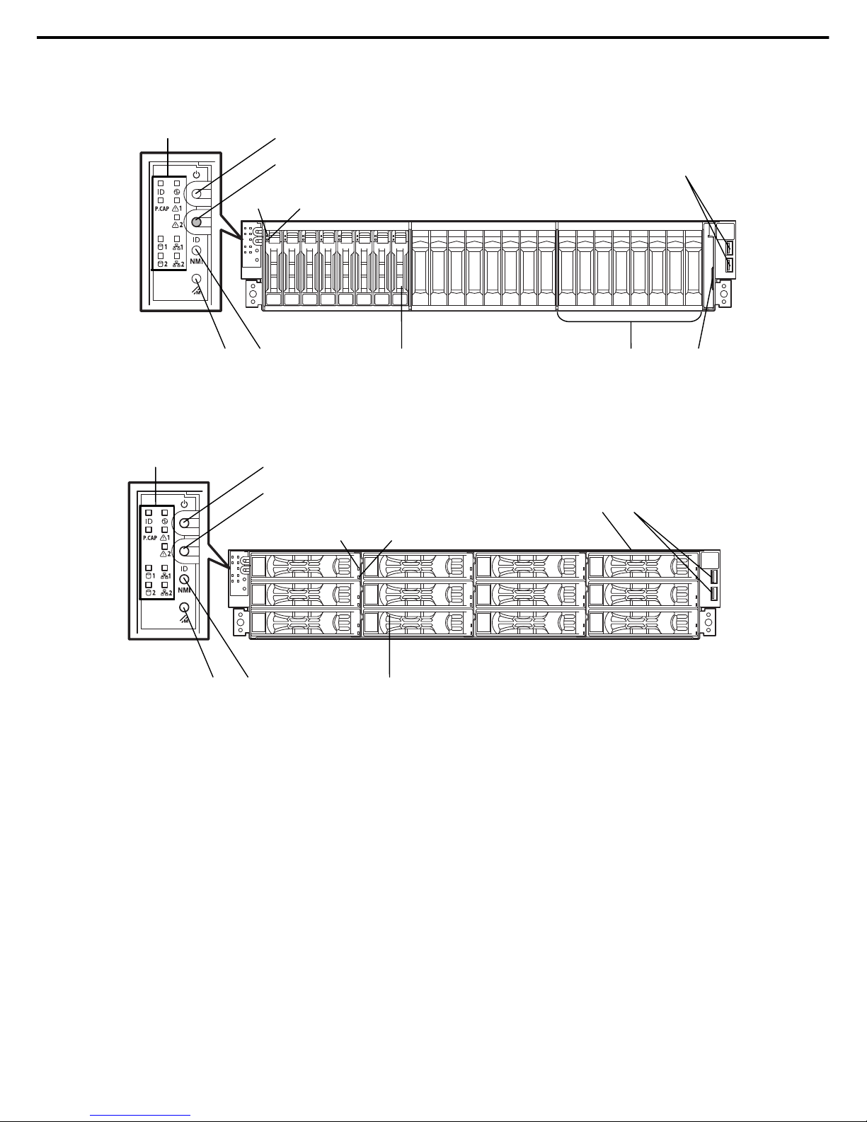
26x 2.5-inch Drive Model
12x 3.5-inch Drive Model
(9) DISK LED
LEDs for showing the hard disk drive status.
The LED provided for each HDD.
(See page 36)
(10) 2.5-inch / 3.5-inch Hard Disk Drive Bay
Bays for installing HDDs.
(11) USB Connectors (front)
Connectors for connecting USB interface devices.
(12) DUMP Switch (NMI)
A switch for collecting the memory dump.
(13) BMC RESET Switch
A switch for resetting BMC of this server. Use the switch
only when there is a problem with EXPRESSSCOPE
Engine 3 (BMC).
To use this switch, press it at least five seconds.
(14) POWER Switch
A switch for turning on/off the server. Press once to turn on
the server. POWER LED lights when it is on. Press it again
to turn off the server. Hold down the switch for four seconds
or more to forcibly turn off the server.
(15) Unit ID (UID) Switch
A switch for turning on/off UID LED.
Pressing the switch once turns on UID LED and pressing
again turns off the LED.
(16) Pull-out Tab
A tab for showing the part number and serial number of the
server.
(17) 2.5-inch Additional HDD Cage Bay
A bay for installing 2.5-inch Additional HDD cage.
(9)-1 (9)-2
(16)
(11)
(13) (12) (10)
(17)
(16)
(11)
(14)
(15)
(9)-1 (9)-2
See 4.1 Front View
(With Front Bezel).
(13) (12) (10)
(14)
(15)
See 4.1 Front View
(With Front Bezel).
Page 28
4. Names and Functions of Parts
Express5800/R120g-2E User's Guide
28
Chapter 1 General Description
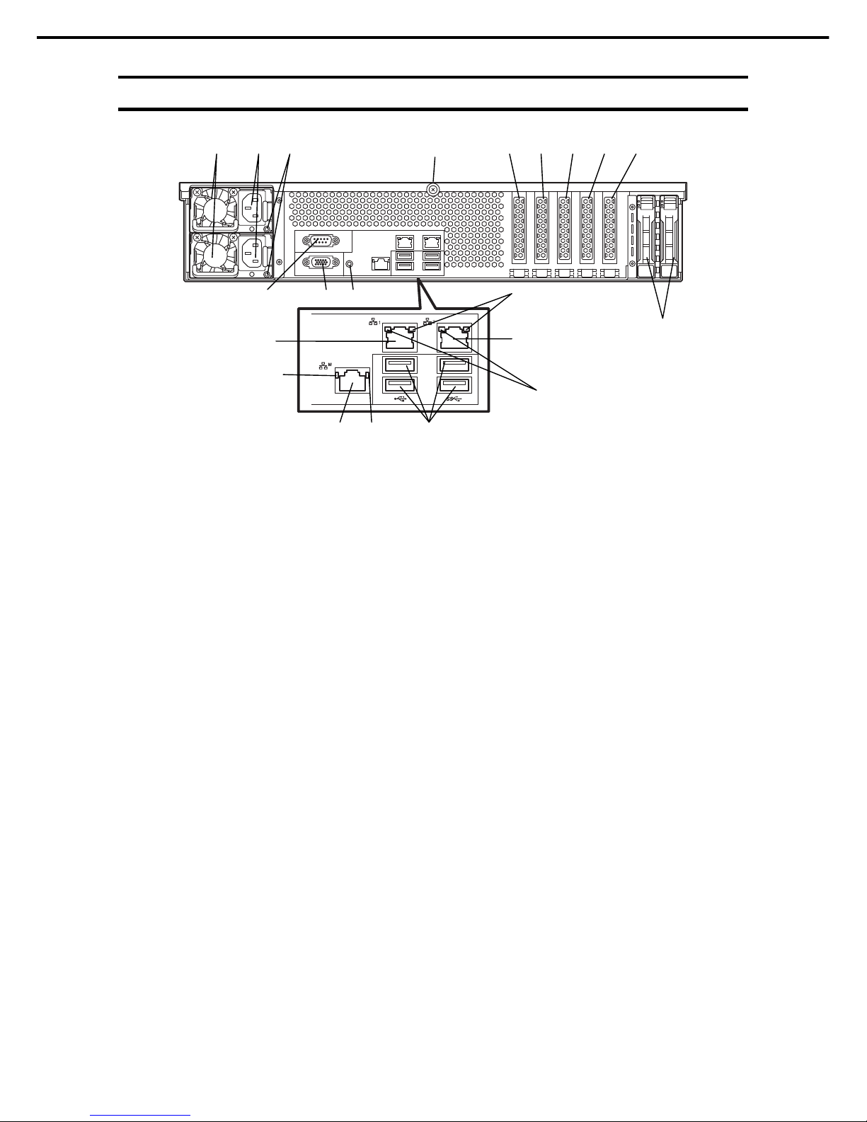
4.3
Rear View
(1) Power Unit
A power supply for supplying the DC power to the server.
(2) AC Inlet
A socket for connecting the power cord.
(3) AC POWER LED
An LED for showing the power supply status.
(See page 38)
(4) Cap Screw
A screw for fixing the top cover.
(5) Slot for PCI Card
Slots for installing PCI cards.
"1", "2", "3", "4", and "5" indicate PCI slot number.
(6) USB Connectors
Connectors for connecting USB interface devices.
(7) LINK/ACT LED
LEDs for showing the access status of LAN.
(See page 37)
(8) LAN Connectors
LAN connectors which supports
1000BASE-T/100BASE-TX/10BASE-T.
(10)-1: LAN1 port connector
(10)-2: LAN2 port connector
If Shared BMC LAN feature is enabled in ROM Utility, LAN
connector 1 can also be used as the management LAN port.
Sharing port is not recommended from the point of performance
and security.
(9) SPEED LED
LEDs for showing the transfer speed of LAN ports.
(See page 37)
(10) Management LAN Connector
A LAN connector which supports
1000BASE-T/100BASE-TX/10BASE-T. This port
cannot be used as a data transmission port.
This port is used for connecting to EXPRESSSCOPE
Engine 3.
(11) Serial Port A (COM) Connector
A connector for connecting serial interface devices.
This cannot connect to a network line directly.
(12) Display Connector
A connector for connecting a display.
This connector cannot be used with the display
connector on front panel at the same time.
(13) UID Switch/LED
A switch for turning on/off UID LED.
Pressing the switch once turns on UID LED and
pressing again turns off the LED.
Commands from the software also cause it to turn on
or flash.
(See page 35)
(14) 2.5-inch Additional HDD Cage Bay
A bay for installing 2.5-inch Additional HDD cage
(Rear). Not available in 16x 2.5-inch drive models.
(5)-1 (5)-2 (5)-3 (5)-4 (5)-5
(8)-2
(8)-1
(7)
(10) (9) (6)
(11) (12) (13)
(1) (2) (3) (4)
(14)
(7)
(9)
Page 29
4. Names and Functions of Parts
Express5800/R120g-2E User's Guide
29
Chapter 1 General Description
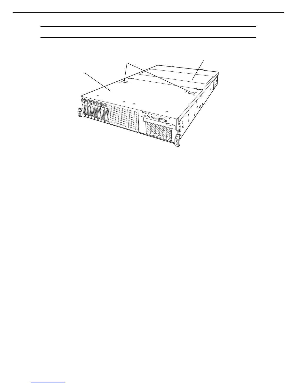
4.4
External View
(1) Top Cover (front)
(2) Release Button
(3) Top Cover (rear)
(2)
(1)
(3)
Page 30
4. Names and Functions of Parts
Express5800/R120g-2E User's Guide
30
Chapter 1 General Description
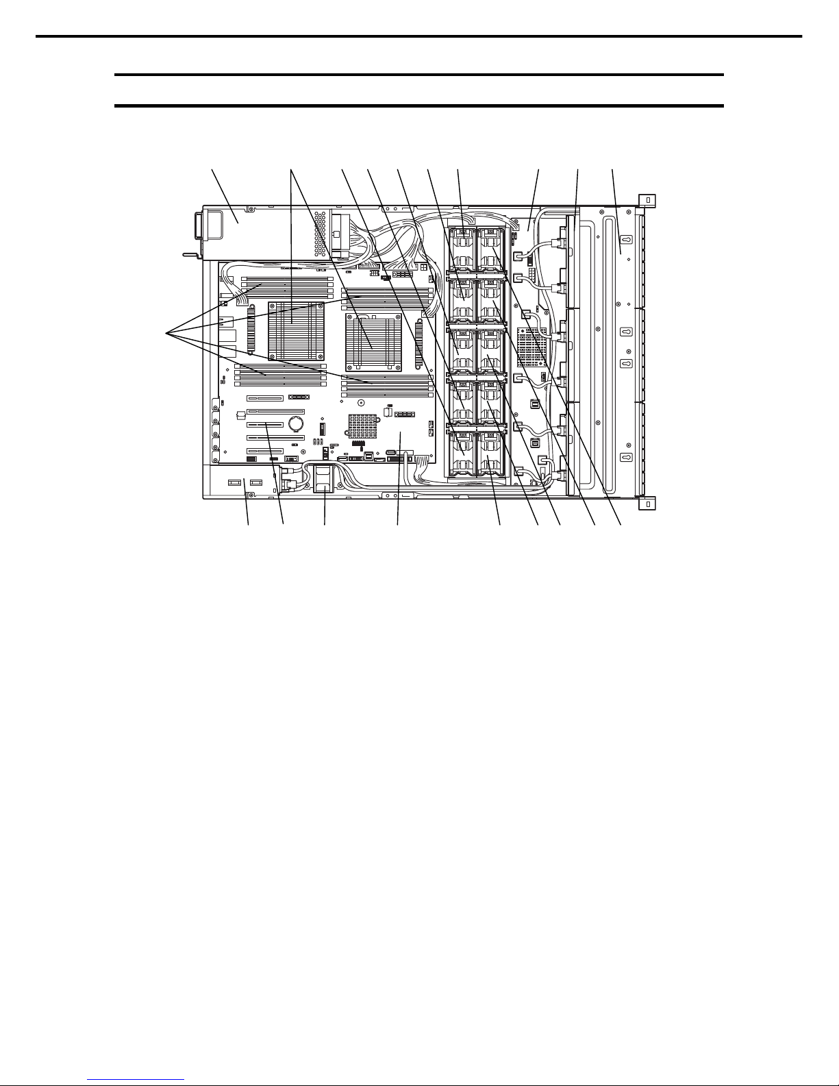
4.5
Internal View
The duct and support bar are not shown in the figure below.
(1) Protective Cover
(2) Backplane
(3) Cooling Fan
-1 FAN5F (optional) -6 FAN5R
-2 FAN4F (optional) -7 FAN4R
-3 FAN3F (optional) -8 FAN3R
-4 FAN2F (optional) -9 FAN2R
-5 FAN1F (optional) -10 FAN1R
16x 2.5-inch drive models:
FAN2R to FAN5R are factory installed. FAN2F to FAN5F* are used
when optional redundant fan unit is installed.
26x 2.5/3.5-inch drive models:
FAN1R to FAN5R are factory installed. FAN1F to FAN5F* are used
when optional redundant fan unit is installed.
(4) Processor (CPU)
Mounted beneath the heat sink.
(5) DIMM (optional)
(6) Motherboard
(7) Power Supply Unit
(8) Expander Card
(9) Rear Cooling Fan
(10) 2.5-inch Additional Rear HDD Cage
(11) PCI Slots
(3)-1 (3)-2 (3)-3 (3)-4 (3)-5
(3)-6 (3)-7 (3)-8 (3)-9 (3)-10 (1) (2) (2) (8) (4) (7)
(10) (9) (6) (11)
(5)
Page 31

4. Names and Functions of Parts
Express5800/R120g-2E User's Guide
31
Chapter 1 General Description
4.6
Motherboard
(2) (1)-2 (24) (3)
(5)
(7)-1 (7)-2 (8)-2
(21)
(2)
(2)
(8)-1
(1)-1
(2)
(27)
(26)
(25)-1
(25)-2
(10)
(20)-1
(15) (16) (14) (12)
(9)
(18) (13)
(19) (23) (22)
(4) (6)
(11)
(20)-2
(20)-3
(20)-4
(20)-5
(17)
Page 32

4. Names and Functions of Parts
Express5800/R120g-2E User's Guide
32
Chapter 1 General Description
(1) Processor (CPU) Socket
-1 Processor #1 (CPU#1)
-2 Processor #2 (CPU#2)
(2) DIMM Socket
(3) Front Panel Connector
(4) Fan Board Connector
(5) Connector for SATA Optical Disk/Backup Unit Powe
r
Supply
(6) Connector for HDD Cage Power Supply
(7) Connector for MB Power Supply
(8) Connector for CPU Power Supply
(9) Lithium Battery
(10) Clear CMOS Jumper
(11) Clear Password Jumper
(12) USB Memory Module Connector
(13) SGPIO Cable Connector
(14) Connector for Optional COM
Connect an additional RS-232C connector kit N8117-01A
to use this port as a serial port B.
(15) SPI Flash Mezzanine Connector
EXPRESSSCOPE Profile Key (SPI Flash memory) has
been installed, where BIOS and BMC configuration data is
stored. Relocate it when replacing motherboard to inherit
configuration data.
(16) Front Display Connector
(17) TPM kit Connector
(18) SATA Optical Disk Drive Connector
(19) SATA Connector
(20) PCI Connector
The last digit number indicates PCI card slot number. Fo
r
available card, see Chapter 2 (1.15 PCI Card).
(21) Connector for External Devices
(See page 31.)
(22) Front USB Connector
(23) Connector for USB Backup Unit
(24) Connector for Power Supply BP Signal
(25) Connector for Rear Cooling Fan
-1 For FAN6R (lower fan)
-2 For FAN7R (upper fan)
(26) RAID Configuration Jumper
(27) Buzzer
Page 33

4. Names and Functions of Parts
Express5800/R120g-2E User's Guide
33
Chapter 1 General Description
4.7
Status Indicators
4.7.1
POWER LED ( )
POWER LED indicates power ON/OFF status of the server.
POWER LED pattern Description
On (green) The server is normally powered on.
Off The server is off-powered.
The server is in halt status.
4.7.2
STATUS LED 1, 2 ( )
While hardware is operating normally, STATUS LED 1 lights green. STATUS LED 2 is off.
STATUS LED 1 is off or STATUS LED 2 lights/flashes amber if there is a hardware failure.
Tips
If NEC ESMPRO is installed, you can view error logs to check the causes of
failures.
STATUS LED 1, 2 pattern
Description Solution
STATUS LED 1 STATUS LED 2
On (green) Off The server is operating normally. –
On (green) On (amber) Initialization of BMC is in progress. Wait until initialization completes.
Flashing (green) Off Memory is in a degraded state Identify the device in degraded state by using
BIOS Setup Utility (SETUP), and replace it as
soon as possible.
Operating while CPU error is detected.
In redundant power configuration, power is
not supplied to either of power unit.
Off Off The power is off. Turn on the server.
POST is in progress. Wait for a while. STATUS LED will turn green
after POST completes.
Watchdog timer expired. Turn the power off and then turn it on.
If POST screen displays any error message,
take notes of the message, and contact your
sales representative.
Memory dump is being requested.
Note: It remains green if the dump is caused
by software.
Wait until the memory dump is completed.
Page 34

4. Names and Functions of Parts
Express5800/R120g-2E User's Guide
34
Chapter 1 General Description
STATUS LED 1, 2 pattern
Description Solution
STATUS LED 1 STATUS LED 2
Off On (amber) A temperature alarm was detected. Check the internal fan for dusts. Also check if
the fan unit is properly connected.
If the LED indication does not change, contact
your sales representative.
A CPU error occurred. Turn the power off and then turn it on.
If POST displays any error message, take
notes of the message, and contact your sales
representative.
Abnormal CPU temperature is detected.
A PCI system error occurred
A PCI parity error occurred
A PCI bus error occurred.
A voltage alarm was detected. Contact your sales representative.
Fan error was detected.
Sensor error was detected.
A CPU temperature alarm was detected.
An error occurred on Intel Node Manager
(one of the features of EXPRESSSCOPE
Engine 3).
Off Flashing
(amber)
Power Supply Unit is failing (in power
redundant configuration).
Contact your sales representative.
A fan alarm was detected. Check if the internal fan cable is properly
connected.
If the LED indication does not change, contact
your sales representative.
A temperature warning was detected. Check the internal fan for dusts. Also check if
the fan unit is properly connected.
If the LED indication does not change, contact
your sales representative.
A voltage warning was detected Contact your sales representative.
One or more hard disk drives are failing
(excluding RAID0 or non-RAID
configuration).
A correctable memory error has often
occurred.
Replace the failure DIMM.
Page 35

4. Names and Functions of Parts
Express5800/R120g-2E User's Guide
35
Chapter 1 General Description
4.7.3
LINK/ACT LED ( 1, 2, M)
LINK/ACT LED on front panel indicates the status of LAN port.
LINK/ACT LED pattern Description
On (green) The server is connected with network normally.
Flashing (green) The server is accessing network.
Off The server is disconnected from network.
4.7.4
Optical Disk Drive Access LED (option)
The LED for optical disk drive at the front of the server flashes when a CD or DVD is being accessed.
4.7.5
UID LED (ID)
UID LED is provided one each at the front and rear of the server. If you press UID Switch provided at the
front or rear of the server, the light turns on. If you press it again, the light turns off. It flashes when
commands from software are received. This LED is used to identify the target server among multiple servers
installed in a rack. Especially when performing maintenance from behind the server, lighting the LED will
help you to identify which server to work with.
UID LED pattern Description
On (blue) The UID switch is pressed.
Off The UID switch is not pressed.
4.7.6
Power Capping LED
Power Capping LED indicates the status of Power Capping feature as shown below.
Power Capping LED pattern Description
On (green) Power Capping feature is enabled.
Flashing (green) Power Capping is enabled and power control (capping) is working.
Off Power Capping feature is disabled.
Note
The Power Capping LED seems to be lit or flashing amber when STATUS LED is lit or
flashing amber. The amber STATUS LED indicates a hardware failure. Contact your sales
representative.
Page 36

4. Names and Functions of Parts
Express5800/R120g-2E User's Guide
36
Chapter 1 General Description
4.7.7
LED on a hard disk drive
Each HDD is equipped with DISK LED.
DISK1, 2 LED pattern
Description Solution
DISK LED 1 DISK LED 2
Flashing (green) Off Hard disk drive is being accessed. –
Off On (amber)
(only when RAID
system is
configured)
Hard disk drive is failing. Contact your sales representative.
Flashing (green) Flashing (amber)
(only when RAID
system is
configured)
Rebuild is in progress.
When the failed hard disk drive is replaced,
rebuild process starts automatically (auto
rebuild feature).
–
Off Off Hard disk drive is halted. –
Important
Observe the following precautions whenever you use the auto rebuild
feature.
• Do not turn off or reboot the server while a HDD is being rebuilt.
• Wait at least 90 seconds before installing a HDD after removing one.
• Do not replace a HDD while another HDD is being rebuilt.
DISK LED 1 (green)
DISK LED 1 (green)
DISK LED 2 (amber)
DISK LED 2 (amber)
Page 37

4. Names and Functions of Parts
Express5800/R120g-2E User's Guide
37
Chapter 1 General Description
4.7.8
LEDs for LAN connectors
The LAN connectors on rear panel have LINK/ACT LED and SPEED LED.
• LINK/ACT LED (
1, 2, M)
This LED indicates the status of the LAN port.
LINK/ACT LED pattern Description
On (green) The server is connected with network normally.
Flashing (green) The server is accessing network.
Off The server is disconnected from network.
• SPEED LED (
1, 2, M)
This LED indicates which network interface is used.
―The standard LAN ports (
1 and 2) support 1000BASE-T, 100BASE-TX, and 10BASE-T.
―The management LAN port (
M) supports 1000BASE-T, 100BASE-TX, and 10BASE-T.
SPEED LED pattern Description
On (amber) The port is operating with 1000BASE-T interface.
On (green) The port is operating with 100BASE-TX interface.
Off The port is operating with 10BASE-T interface.
LINK/ACT
LED
Management
LAN
connector
SPEED
LED
LINK/ACT LED SPEED LED
LAN
connector
1
LAN
connector
2
LINK/ACT LED SPEED LED
Page 38

4. Names and Functions of Parts
Express5800/R120g-2E User's Guide
38
Chapter 1 General Description
4.7.9
AC POWER LED on Power Unit
The power unit is equipped with AC POWER LED.
The following table lists LINK/ACT LED patterns.
AC POWER LED pattern Description Solution
On (green) The server is powered on. –
Flashing (green) The power cable is connected and AC power is
supplied.
–
Cold Redundant feature is enabled. –
On (amber) The power cable is not connected in redundant
power configuration.
Connect the power cable.
Power unit is failing. Contact your sales representative.
Flashing (amber) Power unit is failing. Contact your sales representative.
Off The power is not supplied to the server. Connect the power cable. If it is already
connected, contact your sales representative.
A
C POWER LED
Page 39

4. Names and Functions of Parts
Express5800/R120g-2E User's Guide
39
Chapter 1 General Description
4.7.10
Global HDD LED1,2(1- -2)
Global HDD LED indicates the status of internal hard disk drives.
Status of Global HDD LED 1 and 2
Description Action
Global HDD
LED1
Global HDD
LED2
Blinking (green) Off Hard disk drive is being accessed.
-
Off On (amber)
(only when RAID
system is
configured)
Hard disk drive is failing. Contact your sales representative.
Blinking (green) Blinking (amber)
(only when RAID
system is
configured)
Rebuild is in progress.
When the failed hard disk drive is
replaced, rebuild process starts
automatically (auto rebuild feature).
-
Off Off Hard disk drive is halted.
-
Important
Observe the following precautions whenever you use the auto rebuild
feature.
• Do not turn off or reboot the server while a HDD is being rebuilt.
• Wait at least 90 seconds before installing a HDD after removing one.
• Do not replace a HDD while another HDD is being rebuilt.
Page 40

Express5800/R120g-2E User's Guide
40
NEC Express5800 Series
Express5800/R120g-2E
Preparations
This chapter describes preparations for using this server.
1. Installing Internal Optional Devices
Describes how to install or remove optional devices.
You can skip this section if you do not add any optional devices.
2. Installation and Connection
Describes how to place the server and connect the cables.
Page 41

1. Installing Internal Optional Devices
Express5800/R120g-2E User's Guide
41
Chapter 2 Preparations
1.
Installing Internal Optional Devices
This section describes the instructions for installing supported optional devices and precautions.
If you did not purchase any optional devices, you can skip this section.
Important
Use only the devices and cables specified by NEC. You will be charged to
repair damages, malfunctions, and failures caused by the use of any devices
or cables not specified for use with this server even within the warranty
period.
1.1
Safety Precautions
Be sure to observe the following precautions to install and remove optional devices properly and safely.
WARNING
Be sure to observe the following precautions to use the server safety. Failure to
observe the precautions may cause death or serious injury. For details, see
Safety Precautions and Regulatory Notices.
• Do not disassemble, repair, or modify the server.
• Do not remove the lithium battery, NiMH battery, or Li-ion battery.
• Disconnect the power plug when installing and removing devices.
CAUTION
Be sure to observe the following precautions to use the server safely. Failure to
observe the precautions may cause burns, injury, and property damage. For
details, see Safety Precautions and Regulatory Notices.
• Do not drop
• Do not leave the server being pulled out.
• Make sure to complete installation.
• Do not install with the cover removed.
• Do not get your fingers caught.
• High temperature
• Electrical shock
Page 42

1. Installing Internal Optional Devices
Express5800/R120g-2E User's Guide
42
Chapter 2 Preparations
1.2
Anti-static Measures
The server contains static-sensitive components. Follow the measures below to avoid a failure caused by static
electricity when installing or uninstalling any optional device.
• Wearing Anti-static Wrist Strap or Anti-static Gloves
Wear a wrist strap on your wrist and connect the wire to the chassis. If there is no wrist strap, touch an
unpainted metal surface of the chassis connected to the ground to discharge static electricity from your body
before touching the component. Touch the metal part occasionally to discharge the static electricity while
working on the component.
• Checking the Workplace
– Work on an anti-static floor or concrete floor.
– If you work on a place where static electricity is likely to be generated (such as carpet), be sure to
provide anti-static protection.
• Using the Work Table
Place the server on a mat with Electrostatic Discharge (ESD) protection.
• Clothing
– Do not wear wool or synthetic clothes.
– Wear anti-static shoes.
– Remove a ring, bracelet, wrist watch, and any kind of metal accessories.
• Handling of Components
– Keep the component in an anti-static bag until you install it to the server.
– Hold the component by the edges to avoid touching any terminals or mounting parts.
– Place the component in an anti-static bag when storing or moving them.
• Handling of Cables
When connecting a cable (a long LAN cable), static electricity may also be charged due to friction against
the floor. Connecting the charged cable to the server will cause damage to the internal devices of the server.
It is recommended to use a product such as electrostatic discharge kit to eliminate the static charge before
connecting the cable.
• Installing and Uninstalling the Optional Device
– To avoid electric hazard and malfunction, be sure to turn off the power switch of the server and unplug
the power cord from the outlet before installing or uninstalling any optional device.
– If the device is a hot-plug device, you do not need to turn off the power switch and unplug the power
cord.
– The device contains static-sensitive electronic components. When installing or uninstalling the optional
device, wear an anti-static wrist strap on your wrist to avoid a failure caused by the static electricity. To
use the strap, connect the wire to the chassis.
Page 43

1. Installing Internal Optional Devices
Express5800/R120g-2E User's Guide
43
Chapter 2 Preparations
1.3
Overview of Installation and Removal
Install/remove components by using the following procedure.
Installing/removing internal components except for hard disk drives, fan unit, and power supply unit should be
done after dismounting the server from the rack.
CAUTION
Be sure to observe the following precautions to use the server safely. Failure to
observe the precautions may cause burns, injury, and property damage. For
details, see Safety Precautions and Regulatory Notices.
• Do not drop the server
• Do not leave the server pulled out of the rack
• Replace the cover after installing components
• Beware of high temperatures
• Do not get your fingers caught when installing components
1. If the server is mounted on a rack, use the UID switch to identify the target server.
See Chapter 2 (1.4 Confirming Servers (UID Switch)).
2. Remove Front Bezel.
See Chapter 2 (1.5 Removing Front Bezel).
3. If the server is ON, turn it off.
See Chapter 3 (6. Turning Off the Server).
4. Disconnect the power cord from the outlet and the server.
Important
• After disconnecting the power cord from the server, wait for at least 30
seconds before continuing to work because the components such as
cooling fan on the motherboard might still be operating for about 30
seconds even after the power cord was disconnected.
• Make sure the AC POWER LED on power supply unit is unlit.
5. If you want to install hard disk drives only, go to step 14. If not, pull out the server from the rack and put it
on a flat rigid desk. See Chapter 2 (2.1 Installation) for details.
Important Do not leave the server being pulled out from the rack.
6. Remove Top Cover.
See Chapter 2 (1.6 Removing Top Cover).
7. Remove Support Bar.
See Chapter 2 (1.7 Removing Support Bar).
8. Remove Air Duct.
See Chapter 2 (1.8 Removing Support BarAir Duct).
Page 44

1. Installing Internal Optional Devices
Express5800/R120g-2E User's Guide
44
Chapter 2 Preparations
9. Depending on the components to be installed or removed, follow the procedure in order.
See Chapter 2 (1.9 TPM Kit to 1.20 Use of Internal Hard Disk Drives in the RAID System).
10. Mount Air Duct.
See Chapter 2 (1.22 Air Duct)..
11. Mount Support Bar.
See Chapter 2 (1.22 Installing Support Bar).
12. Attach Top Cover.
See Chapter 2 (1.23 Installing Top Cover).
13. Mount the server onto the rack.
See Chapter 2 (2.1.2 (1) Installation).
14. Install hard disk drives.
See Chapter 2 (1.24 2.5-inch Hard Disk Drive or 1.25 3.5-inch Hard Disk Drive).
15. Install power supply units.
See Chapter 2 (1.26 Power Supply Unit).
16. Attach Front Bezel.
See Chapter 2 (1.27 Installing Front Bezel).
This is the end of the installation or removal procedures for internal optional devices.
Continue the setup with reference to Chapter 2 (2.2 Connection).
Page 45

1. Installing Internal Optional Devices
Express5800/R120g-2E User's Guide
45
Chapter 2 Preparations
1.4
Confirming Servers (UID Switch)
Using Unit ID (UID) Switch helps you to identify the target server.
When the server is working, before you turn the server off or disconnect a cable from the server, be sure to
identify the target server by using UID Switch/LED first.
To turn UID LED on, press UID Switch. When it is pressed again, the LED will be off.
<Front View> 16x 2.5-inch Drive Model
<Front View> 26x 2.5-inch Drive Model / 3.5-inch Drive Model
<Rear View>
ID
UID switch
UID switch
UID switch
Page 46

1. Installing Internal Optional Devices
Express5800/R120g-2E User's Guide
46
Chapter 2 Preparations
1.5
Removing Front Bezel
Remove Front Bezel when pressing POWER Switch or removing Top Cover.
1. Insert the attached Bezel Lock Key into the key slot and turn the key to the front bezel side while
pressing it lightly to release the lock.
2. Hold the left end of front bezel and pull the right end toward you about 10 cm. Check that the hook in left
is removed as illustrated in the figure below and remove the left end from the chassis.
3. Confirm that the left side of front bezel is unlocked, then hold the left end and pull it toward you to remove
the front bezel from chassis.
解除 ロック
Locked
Unlocked
(2) Pull and rotate about 10
degrees
(3) Pull the bezel
Views from above
Hook
(1) Hold the
handle
Page 47

1. Installing Internal Optional Devices
Express5800/R120g-2E User's Guide
47
Chapter 2 Preparations
Note Be careful not to press POWER Switch.
Important If you fail to remove the front bezel properly, the front bezel might be
damaged.
Page 48

1. Installing Internal Optional Devices
Express5800/R120g-2E User's Guide
48
Chapter 2 Preparations
1.6
Removing Top Cover
Remove Top Cover when installing or removing the optional component or change internal cable connection.
1. See steps 1 to 5 in Chapter 2 (1.3 Overview of Installation and Removal) for preparations.
2. Slide Top Cover (front) toward the front of the server while pressing Release Button on the cover.
3. Lift Top Cover (front), and remove it from the server.
Tips
The screw hole on the place where front and rear top covers overlap each other, is
not used.
4. Loosen Cap Screw of Top Cover (rear), and slide the top cover (rear) toward the rear of the server.
5. Lift Top Cover (rear) and remove it from the server.
Page 49

1. Installing Internal Optional Devices
Express5800/R120g-2E User's Guide
49
Chapter 2 Preparations
1.7
Removing Support Bar
Remove Support Bar when installing or removing the following component:
TPM Kit Processor (CPU)
DIMM (memory module) Flash backup unit for RAID controller
Backup device PCI card
Additional 2.5-inch HDD Cage Additional 2.5-inch HDD Cage (Rear)
2.5-inch PCIe SSD installation kit
1. See steps 1 to 7 in Chapter 2 (1.3 Overview of Installation and Removal) for preparations.
2. Remove the two screws from Support Bar.
3. Lift Support Bar, and remove it from the server.
Page 50

1. Installing Internal Optional Devices
Express5800/R120g-2E User's Guide
50
Chapter 2 Preparations
1.8
Removing Air Duct
Remove the air duct when installing or removing the following component or changing internal cable connection:
TPM Kit Processor (CPU)
DIMM (memory module) Flash backup unit for RAID controller
Backup device PCI card
Additional 2.5-inch HDD Cage Additional 2.5-inch HDD Cage (Rear)
2.5-inch PCIe SSD installation kit
1. See steps 1 to 8 in Chapter 2 (1.3 Overview of Installation and Removal) for preparations.
2. Lift the air duct, and remove it from the server.
Important Before removing the air duct, put cables aside. Otherwise, cables may be damaged if
they are pulled together with air duct.
Page 51

1. Installing Internal Optional Devices
Express5800/R120g-2E User's Guide
51
Chapter 2 Preparations
1.9
TPM Kit
This section describes the procedure for installing optional TPM Kit.
1.9.1
Installation
Install TPM Kit in the following procedure.
1. See steps 1 to 7 in Chapter 2 (1.3 Overview of Installation and Removal) for preparations.
2. Install TPM Kit and secure it by pushing the nylon rivet attached to TPM Kit.
Important The TPM kit once installed cannot be removed.
Ask your sales representative for removal of TPM Kit.
Connector for TPM Kit
Page 52

1. Installing Internal Optional Devices
Express5800/R120g-2E User's Guide
52
Chapter 2 Preparations
1.10
Processor (CPU)
You can configure the multi-processor system by adding an optional processor (CPU).
Important
• You must avoid static electricity to work with the procedure below. For
details, see Chapter 2 (1.2 Anti-static Measures).
• Make sure to use the CPU authorized by NEC. Installing a third-party CPU
may cause a failure of the CPU as well as the motherboard. Repair of the
server due to failures or damage resulted from installing such a CPU will
be charged.
Tips
After adding the processor, Windows records the event log to System category of
Event Viewer, but it is no problem for operation.
1.10.1
Maximum number of processor cores supported by this server
The maximum number of processor cores (logical processors) available on the server depends on the
architecture (x86 architecture) and OS specs.
Maximum number of processor cores
OS
The maximum number of
logical processors
supported by OS
The maximum number of logical
processors supported by this
server
Microsoft Windows Server 2008 R2 Standard (x64)
Microsoft Windows Server 2008 R2 Enterprise (x64)
256 *1 56
Microsoft Windows Server 2012 Standard
Microsoft Windows Server 2012 Datacenter
Microsoft Windows Server 2012 R2 Standard
Microsoft Windows Server 2012 R2 Datacenter
640 *1 56
VMware ESXi 5.5
VMware ESXi 6.0
320 56
*1: When Hyper-V is used, the maximum number of logical processors is as shown below:
Windows Server 2008 R2: 64
Windows Server 2012, Windows Server 2012 R2: 320
Page 53

1. Installing Internal Optional Devices
Express5800/R120g-2E User's Guide
53
Chapter 2 Preparations
1.10.2
Installation
Follow the steps below to install the CPU.
Note CPU#1 heat sink and CPU#2 heat sink differ.
When adding the CPU, use optional heat sink.
1. See steps 1 to 8 in Chapter 2 (1.3 Overview of Installation and Removal) for preparations.
2. Locate the CPU socket to which you are going to install a CPU.
3. Remove the protective cover from the CPU socket.
Note Keep the removed protective cover for future use.
4. Push down the socket lever marked with →" to unlatch it from the hook, and then slowly open
the lever until it stops.
5. Push down the socket lever marked with "← " to unlatch it from the hook, and then slowly open the
lever until it stops.
Page 54

1. Installing Internal Optional Devices
Express5800/R120g-2E User's Guide
54
Chapter 2 Preparations
6. Lift the plate.
Important Do not touch the socket contacts.
7. Put the additional CPU on the CPU socket slowly and gently.
For easy installation, hold edges of the CPU with your thumb and index fingers so that the notch is
aligned with the key on the CPU socket.
Important Be sure to hold the CPU only at the edges. Pay attention not to touch the
bottom of the CPU (pin section).
Note
• Insert the CPU while aligning the notch on the CPU with the key on the CPU
socket.
• Bring down the CPU straight without tilting or sliding it in the socket.
8. Press the processor lightly onto the CPU socket, and then pull down the CPU socket holder.
Key
Notch
Pin mark
Pin mark
Page 55

1. Installing Internal Optional Devices
Express5800/R120g-2E User's Guide
55
Chapter 2 Preparations
9. Push down and lock the lever on the side marked "← ".
10. Push down and lock the lever on the side marked " →".
11. Put the heat sink on the CPU and secure it by using four screws.
When securing the screws, temporarily tighten the four screws in a crosswise pattern, and then tighten
them securely. Make sure to align each screw and screw hole; otherwise, the screws may damage the
motherboard.
When putting the heat sink on the CPU, also pay attention not to touch the components around the CPU
socket.
1
3
2
4
Page 56

1. Installing Internal Optional Devices
Express5800/R120g-2E User's Guide
56
Chapter 2 Preparations
Note The heat sink must be mounted in the predefined direction. Make sure the direction
of heat sink before mounting it.
The label indicating the mounting orientation of the CPU#2 heat sink is affixed to the
side surface of the heat sink.
12. Make sure that the heat sink is installed on a level with the motherboard.
Note
• If the heat sink is not level, remove it, and then install it again.
The following probably causes the heat sink not to be level:
– The CPU is not positioned correctly.
– Some screws are not completely tightened.
• Do not move the secured heat sink.
13. Continue to install or remove internal optional devices, mount and connect the server, and then turn it on.
14. Run BIOS Setup Utility (SETUP) to confirm the following settings. See Chapter 3 (2. BIOS Setup Utility
(SETUP)).
Advanced → Processor Configuration → Processor Information
[CPU ID]
[L2 Cache RAM]
[L3 Cache RAM]
FRONT REAR
Page 57

1. Installing Internal Optional Devices
Express5800/R120g-2E User's Guide
57
Chapter 2 Preparations
1.10.3
Replacement / Removal
To remove CPU, reverse the installation procedure.
When you removed the CPU, be sure to mount the protective cover on the CPU socket.
Important
• Do not remove any CPU unless it is failed.
• To remove the heat sink from the CPU, first turn the heat sink to the left
and right lightly to make sure that the heat sink can be apart from the
CPU.
Removing the heat sink with it adhering to the CPU may cause the CPU
and/or CPU socket to be defected.
Perform the following steps after replacing or removing the CPU.
1. Run BIOS Setup Utility (SETUP) to confirm the following settings. See Chapter 2 (1. System BIOS) in
"Maintenance Guide".
Advanced → Processor Configuration → Processor Information
[CPU ID]
[L2 Cache RAM]
[L3 Cache RAM]
Page 58

1. Installing Internal Optional Devices
Express5800/R120g-2E User's Guide
58
Chapter 2 Preparations
1.11
DIMM
Install a Dual Inline Memory Module (DIMM) to a DIMM socket on the motherboard in the server. The
motherboard provides 16 sockets to install DIMMs.
Important
• You must avoid static electricity to work with the procedure below. For
details, see Chapter 2 (1.2 Anti-static Measures).
• Use only the specified DIMMs. Installing a DIMM from a third party may
damage not only the DIMM but the motherboard. You will be charged to
repair failures or damages caused by the use of such products even
within the warranty period.
Tips
Up to 512 GB (32 GB x 16) can be installed in 2-CPU configuration. Up to 256 GB
(32 GB x 8) can be installed in 1-CPU configuration. No DIMM is factory installed in
standard configuration.
CPU1_DIMM1
CPU1_DIMM5
CPU1_DIMM2
CPU1_DIMM6
CPU1_DIMM8
CPU1_DIMM4
CPU1_DIMM7
CPU1_DIMM3
CPU2_DIMM6
CPU2_DIMM2
CPU2_DIMM5
CPU2_DIMM1
CPU2_DIMM3
CPU2_DIMM7
CPU2_DIMM4
CPU2_DIMM8
Page 59

1. Installing Internal Optional Devices
Express5800/R120g-2E User's Guide
59
Chapter 2 Preparations
1.11.1
Maximum supported memory size
The maximum available memory size on the server depends on the architecture and OS specs.
Maximum memory sizes
OS
The maximum
memory size
supported on each OS
The maximum memory size
supported on the server
Microsoft Windows Server 2008 R2 Standard *1 32 GB 32 GB
Microsoft Windows Server 2008 R2 Enterprise *1 2 TB 512 GB
Microsoft Windows Server 2012 Standard *1
Microsoft Windows Server 2012 Datacenter *1
Microsoft Windows Server 2012 R2 Standard *1
Microsoft Windows Server 2012 R2 Datacenter *1
4 TB 512 GB
VMware ESXi 5.5 *2
VMware ESXi 6.0 *2
4 TB 512 GB
*1: Shown below is the maximum memory size when Hyper-V is used:
- Windows Server 2008 R2 Standard: 32 GB
- Windows Server 2008 R2 Enterprise: 1 TB
- Windows Server 2012, Windows Server 2012 R2: 4TB
*2: Up to 1 TB on virtual machine.
Page 60

1. Installing Internal Optional Devices
Express5800/R120g-2E User's Guide
60
Chapter 2 Preparations
1.11.2
Memory clock
The server supports the memory clock speed of DDRL4-1600/1866/2133/2400MHz but the actual memory
clock speed depends on CPU and memory configuration. The all of DIMMs operate at the same clock speed.
Model Number
(CPU)
DIMM type
Number of
DIMMs
(per 1 CPU)
Clock speed
N8101-1068F
(E5-2603v4)
N8101-1069F
(E5-2609v4)
N8102-686F
4GB DDR4-2400 REG Memory Kit (1x4GB)
N8102-687F
8GB DDR4-2400 REG Memory Kit (1x8GB)
N8102-688F
16GB DDR4-2400 REG Memory Kit (1x16GB)
N8102-689F
32GB DDR4-2400 REG Memory Kit (1x32GB)
Up to 8 sets
(8 DIMMs)
1866 MHz
N8102-691
16GB DDR4-2400 REG Memory Kit (2x8GB)
N8102-692
32GB DDR4-2400 REG Memory Kit (2x16GB)
Up to 4 sets
(8 DIMMs)
N8102-693
16GB DDR4-2400 REG Memory Kit (2x8GB)
N8102-694
32GB DDR4-2400 REG Memory Kit (2x16GB)
Up to 4 sets
(8 DIMMs)
N8101-1070F
(E5-2620v4)
N8101-1071F
(E5-2623v4)
N8101-1072F
(E5-2630v4)
N8102-686F
4GB DDR4-2400 REG Memory Kit (1x4GB)
N8102-687F
8GB DDR4-2400 REG Memory Kit (1x8GB)
N8102-688F
16GB DDR4-2400 REG Memory Kit (1x16GB)
N8102-689F
32GB DDR4-2400 REG Memory Kit (1x32GB)
Up to 8 sets
(8 DIMMs)
2133 MHz
N8102-691
16GB DDR4-2400 REG Memory Kit (2x8GB)
N8102-692
32GB DDR4-2400 REG Memory Kit (2x16GB)
Up to 4 sets
(8 DIMMs)
N8102-693
16GB DDR4-2400 REG Memory Kit (2x8GB)
N8102-694
32GB DDR4-2400 REG Memory Kit (2x16GB)
Up to 4 sets
(8 DIMMs)
N8101-1073F
(E5-2650v4)
N8101-1074F
(E5-2660v4)
N8101-1075F
(E5-2690v4)
N8102-686F
4GB DDR4-2400 REG Memory Kit (1x4GB)
N8102-687F
8GB DDR4-2400 REG Memory Kit (1x8GB)
N8102-688F
16GB DDR4-2400 REG Memory Kit (1x16GB)
N8102-689F
32GB DDR4-2400 REG Memory Kit (1x32GB)
Up to 8 sets
(8 DIMMs)
2400 MHz
N8102-691
16GB DDR4-2400 REG Memory Kit (2x8GB)
N8102-692
32GB DDR4-2400 REG Memory Kit (2x16GB)
Up to 4 sets
(8 DIMMs)
N8102-693
16GB DDR4-2400 REG Memory Kit (2x8GB)
N8102-694
32GB DDR4-2400 REG Memory Kit (2x16GB)
Up to 4 sets
(8 DIMMs)
Page 61

1. Installing Internal Optional Devices
Express5800/R120g-2E User's Guide
61
Chapter 2 Preparations
1.11.3
Memory RAS feature
The server supports the following RAS features. Some restrictions (such as DIMM installation location) are
imposed on using the Memory Mirroring or Memory LockStep Memory Sparing feature. See Chapter 2 (1.11.7
Using Memory RAS feature) for conditions appropriate to your requirements.
• Standard memory feature (x4 SDDC ECC memory)
• Memory Mirroring feature (restrictions imposed on DIMM configuration)
• Memory LockStep feature (x8 SDDC ECC memory) (restrictions imposed on DIMM configuration)
• Memory Sparing feature (restrictions imposed on DIMM configuration)
Supported RAS features depend on additional memory card.
See the table below for RAS features supported by additional memory card.
List of features supported by additional memory card
Model Number and Product Name
Standard
feature
(x4 SDDC)
Memory
Mirroring
feature
Memory
LockStep
feature
(x8 SDDC)
Memory
Sparing
feature
N8102-686F 4GB DDR4-2400 REG Memory Kit (1x4GB)
N/A N/A N/A N/A
N8102-687F 8GB DDR4-2400 REG Memory Kit (1x8GB) N/A N/A N/A N/A
N8102-688F 16GB DDR4-2400 REG Memory Kit (1x16GB)
N/A N/A N/A
N8102-689F 32GB DDR4-2400 REG Memory Kit (1x32GB)
N/A N/A N/A
N8102-691 16GB DDR4-2400 REG Memory Kit (2x8GB)
N/A
N/A
N8102-692 32GB DDR4-2400 REG Memory Kit (2x16GB) N/A
N/A
N8102-693 16GB DDR4-2400 REG Memory Kit (2x8GB)
N/A N/A N/A
N8102-694 32GB DDR4-2400 REG Memory Kit (2x16GB) N/A N/A N/A
: Supported
Page 62

1. Installing Internal Optional Devices
Express5800/R120g-2E User's Guide
62
Chapter 2 Preparations
1.11.4
DIMM installation order
Note
• DIMM installation order in 1-CPU configuration differs from that in 2-CPU
configuration.
• If CPU2 is not installed, CPU2_DIMM1 to CPU2_DIMM8 are disabled.
• See List of features supported by additional memory card in 1.11.3 Memory
RAS feature before using memory RAS feature.
In 1-CPU configuration, install DIMMs starting from the smallest slot number.
In 2-CPU configuration, alternately install DIMMs starting from the smallest slot number of each CPU.
Installation order depends on combination of DIMMs to be installed.
See the table below to find allowable combination of DIMMs, and install DIMMs starting from the largest
capacity and from the smallest slot number.
Model Number
N8102-
686F 687F 688F 689F 691 692 693 694
N8102-686F
N/A N/A N/A N/A
N8102-687F
N/A N/A N/A N/A
N8102-688F
N/A N/A N/A N/A
N8102-689F
N/A N/A N/A N/A
N8102-691 N/A N/A N/A N/A
N/A N/A
N8102-692 N/A N/A N/A N/A
N/A N/A
N8102-693
N/A N/A N/A N/A N/A N/A
N8102-694 N/A N/A N/A N/A N/A N/A
: Allowed to be install together
Page 63

1. Installing Internal Optional Devices
Express5800/R120g-2E User's Guide
63
Chapter 2 Preparations
Slot
DIMM Installation Order
1-CPU configuration 2-CPU configuration
CPU1_DIMM1
1 1
CPU1_DIMM2
2 3
CPU1_DIMM3
3 5
CPU1_DIMM4
4 7
CPU1_DIMM5
5 9
CPU1_DIMM6
6 11
CPU1_DIMM7
7 13
CPU1_DIMM8
8 15
CPU2_DIMM1
−
2
CPU2_DIMM2
−
4
CPU2_DIMM3
−
6
CPU2_DIMM4
−
8
CPU2_DIMM5
−
10
CPU2_DIMM6
−
12
CPU2_DIMM7
−
14
CPU2_DIMM8
−
16
2-CPU
configuration
1-CPU
configuration
1st DIMM
5th DIMM
2nd DIMM
6th DIMM
8th DIMM
4th DIMM
7th DIMM
3rd DIMM
6th DIMM
14th DIMM
8th DIMM
16th DIMM
12th DIMM
4th DIMM
10th DIMM
2nd DIMM
1st DIMM
9th DIMM
3rd DIMM
11th DIMM
15th DIMM
7th DIMM
13th DIMM
5th DIMM
Page 64

1. Installing Internal Optional Devices
Express5800/R120g-2E User's Guide
64
Chapter 2 Preparations
1.11.5
Installation
Install a DIMM by using the following procedure.
1. See steps 1 to 8 in Chapter 2 (1.3 Overview of Installation and Removal) for preparations.
2. Open levers at both ends of the target DIMM slot.
3. Push the DIMM straight into the socket.
When a DIMM is inserted into the socket,
the lever automatically closes.
Important
• Make sure the orientation of the DIMM. The DIMM has a notch, preventing
being incorrectly inserted.
• Do not apply too much pressure when you push a DIMM into the socket.
Doing so can damage the socket or terminal part.
4. Continue to install or remove internal optional devices, mount and connect the server, and turn it on.
5. Confirm that no error messages are displayed in POST screen.
If any error messages are displayed, see Chapter 3 (1. POST Error Message) in "Maintenance Guide".
6. Run BIOS Setup Utility, and select Memory Configuration and then Memory Information from the
Advanced menu. Make sure the capacity of added DIMM is displayed properly.
See Chapter 3 (2. BIOS Setup Utility (SETUP).
7. Select Memory Configuration from the Advanced menu, and then specify Yes for Memory Retest.
After that, select Save Changes and Exit to reboot.
8. If using a Windows OS, see Chapter 1 (7.1 Specifying Memory Dump Settings (Debug Information)) in
"Installation Guide (Windows)".
For other OS, follow the manual of the OS.
Tips
We recommend that the size of paging file be set to the recommended size (total
memory size x 1.5) or more.
Notch
Key
Page 65

1. Installing Internal Optional Devices
Express5800/R120g-2E User's Guide
65
Chapter 2 Preparations
1.11.6
Removal / Replacement
Remove a DIMM in the following procedure.
Note
• When removing a defective DIMM, check error messages displayed at POST or
NEC ESMPRO and check the DIMM socket where the defective DIMM is
installed.
• At least one DIMM needs to be installed for the server to operate.
1. See steps 1 to 7 in Chapter 2 (1.3 Overview of Installation and Removal) for preparations.
2. Open levers of the DIMM socket outward.
The socket is unlocked and DIMM can be
removed.
3. Pull out the DIMM straight.
4. Confirm that no error messages are displayed on POST. If any error message is displayed, see Chapter 3
(1. POST Error Message) in "Maintenance Guide".
5. Run BIOS Setup Utility, select Memory Configuration from the Advanced menu, and then specify Yes
for Memory Retest. After that, select Save Changes and Exit to reboot.
6. If using a Windows OS, see Chapter 1 (7.1 Specifying Memory Dump Settings (Debug Information)) in
"Installation Guide (Windows)".
For other OS, follow the manual of the OS.
Tips
We recommend that the size of paging file be set to the recommended size (total
memory size x 1.5) or more.
Page 66

1. Installing Internal Optional Devices
Express5800/R120g-2E User's Guide
66
Chapter 2 Preparations
1.11.7
Cluster On Die and Early Snoop features
To set the Cluster On Die option to Enabled on Advanced -> Memory Configuration submenu in system BIOS
setup utility (SETUP), note the number of DIMMs to be installed.
• For 1-CPU configuration
Install DIMM on at least all of CPU1_DIMM1 to DIMM3 slots.
• For 2-CPU configuration
Install DIMM on at least all of CPU1_DIMM1 to DIMM3 and CPU2_DIMM1 to DIMM3 slots.
For effective use of the Cluster On Die feature, the recommended number of DIMMs to be installed is as follows:
• For 1-CPU configuration
Install DIMM on CPU1_DIMM1 to DIMM4 slots.
Otherwise, install DIMM on CPU1_DIMM1 to DIMM8 slots.
• For 2-CPU configuration
Install DIMM to CPU1_DIMM1 on DIMM4 and CPU2_DIMM1 to DIMM4 slots.
Otherwise, install DIMM on CPU1_DIMM1 to DIMM8 and CPU2_DIMM1 to DIMM8 slots.
• For 1-CPU configuration (Memory RAS Mode: Independent)
No. of installing
DIMMs
Cluster On Die feature Target DIMM slot
1 Not available CPU1_DIMM1
2 Not available CPU1_DIMM1 to CPU1_DIMM2
3 Available CPU1_DIMM1 to CPU1_DIMM3
4 Available (recommended) CPU1_DIMM1 to CPU1_DIMM4
5 Available CPU1_DIMM1 to CPU1_DIMM5
6 Available CPU1_DIMM1 to CPU1_DIMM6
7 Available CPU1_DIMM1 to CPU1_DIMM7
8 Available (recommended) CPU1_DIMM1 to CPU1_DIMM8
• For 1-CPU configuration (Memory RAS Mode: Independent/ Mirroring/ Lockstep)
No. of installing
DIMMs
Cluster On Die feature Target DIMM slot
2 Not available CPU1_DIMM1 to CPU1_DIMM2
4 Available (recommended) CPU1_DIMM1 to CPU1_DIMM4
6 Available CPU1_DIMM1 to CPU1_DIMM6
8 Available (recommended) CPU1_DIMM1 to CPU1_DIMM8
• For 1-CPU configuration (Memory RAS Mode: Sparing)
No. of installing
DIMMs
Cluster On Die feature Target DIMM slot
2 Not available CPU1_DIMM1 & CPU1_DIMM5
4 Not available
CPU1_DIMM1 to CPU1_DIMM2
CPU1_DIMM5 to CPU1_DIMM6
6 Available
CPU1_DIMM1 to CPU1_DIMM3
CPU1_DIMM5 to CPU1_DIMM7
8 Available (recommended) CPU1_DIMM1 to CPU1_DIMM8
Page 67

1. Installing Internal Optional Devices
Express5800/R120g-2E User's Guide
67
Chapter 2 Preparations
• For 2-CPU configuration (Memory RAS Mode: Independent)
No. of installing
DIMMs
Cluster On Die feature Target DIMM slot
1 Not available CPU1_DIMM1
2 Not available CPU1_DIMM1 & CPU2_DIMM1
3 Not available
CPU1_DIMM1 to CPU1_DIMM2
CPU2_DIMM1
4 Not available
CPU1_DIMM1 to CPU1_DIMM2
CPU2_DIMM1 to CPU2_DIMM2
5 Not available
CPU1_DIMM1 to CPU1_DIMM3
CPU2_DIMM1 to CPU2_DIMM2
6 Available
CPU1_DIMM1 to CPU1_DIMM3
CPU2_DIMM1 to CPU2_DIMM3
7 Available
CPU1_DIMM1 to CPU1_DIMM4
CPU2_DIMM1 to CPU2_DIMM3
8 Available (recommended)
CPU1_DIMM1 to CPU1_DIMM4
CPU2_DIMM1 to CPU2_DIMM4
9 Available
CPU1_DIMM1 to CPU1_DIMM5
CPU2_DIMM1 to CPU2_DIMM4
10 Available
CPU1_DIMM1 to CPU1_DIMM5
CPU2_DIMM1 to CPU2_DIMM5
11 Available
CPU1_DIMM1 to CPU1_DIMM6
CPU2_DIMM1 to CPU2_DIMM5
12 Available
CPU1_DIMM1 to CPU1_DIMM6
CPU2_DIMM1 to CPU2_DIMM6
13 Available
CPU1_DIMM1 to CPU1_DIMM7
CPU2_DIMM1 to CPU2_DIMM6
14 Available
CPU1_DIMM1 to CPU1_DIMM7
CPU2_DIMM1 to CPU2_DIMM7
15 Available
CPU1_DIMM1 to CPU1_DIMM8
CPU2_DIMM1 to CPU2_DIMM7
16 Available (recommended)
CPU1_DIMM1 to CPU1_DIMM8
CPU2_DIMM1 to CPU2_DIMM8
• For 2-CPU configuration (Memory RAS Mode: Mirroring/ Lockstep)
No. of installing
DIMMs
Cluster On Die feature Target DIMM slot
4 Not available
CPU1_DIMM1 to CPU1_DIMM2
CPU2_DIMM1 to CPU2_DIMM2
6 Not available
CPU1_DIMM1 to CPU1_DIMM4
CPU2_DIMM1 to CPU2_DIMM2
8 Available (recommended)
CPU1_DIMM1 to CPU1_DIMM4
CPU2_DIMM1 to CPU2_DIMM4
10 Available
CPU1_DIMM1 to CPU1_DIMM6
CPU2_DIMM1 to CPU2_DIMM4
12 Available
CPU1_DIMM1 to CPU1_DIMM6
CPU2_DIMM1 to CPU2_DIMM6
14 Available
CPU1_DIMM1 to CPU1_DIMM8
CPU2_DIMM1 to CPU2_DIMM6
16 Available (recommended)
CPU1_DIMM1 to CPU1_DIMM8
CPU2_DIMM1 to CPU2_DIMM8
Page 68

1. Installing Internal Optional Devices
Express5800/R120g-2E User's Guide
68
Chapter 2 Preparations
• For 2-CPU configuration (Memory RAS Mode: Sparing)
No. of installing
DIMMs
Cluster On Die feature Target DIMM slot
4 Not available
CPU1_DIMM1 & CPU1_DIMM5
CPU2_DIMM1 & CPU2_DIMM5
6 Not available
CPU1_DIMM1 to CPU1_DIMM2
CPU1_DIMM5 to CPU1_DIMM6
CPU2_DIMM1 & CPU2_DIMM5
8 Not available
CPU1_DIMM1 to CPU1_DIMM2
CPU1_DIMM5 to CPU1_DIMM6
CPU2_DIMM1 to CPU2_DIMM2
CPU2_DIMM5 to CPU2_DIMM6
10 Not available
CPU1_DIMM1 to CPU1_DIMM3
CPU1_DIMM5 to CPU1_DIMM7
CPU2_DIMM1 to CPU2_DIMM2
CPU2_DIMM5 to CPU2_DIMM6
12 Available
CPU1_DIMM1 to CPU1_DIMM3
CPU1_DIMM5 to CPU1_DIMM7
CPU2_DIMM1 to CPU2_DIMM3
CPU2_DIMM5 to CPU2_DIMM7
14 Available
CPU1_DIMM1 to CPU1_DIMM8
CPU2_DIMM1 to CPU2_DIMM3
CPU2_DIMM5 to CPU2_DIMM7
16 Available (recommended)
CPU1_DIMM1 to CPU1_DIMM8
CPU2_DIMM1 to CPU2_DIMM8
Page 69

1. Installing Internal Optional Devices
Express5800/R120g-2E User's Guide
69
Chapter 2 Preparations
1.11.8
Using Memory RAS feature
This server has RAS feature including Standard Memory feature (x4 SDDC ECC memory), Memory Mirroring
feature, Memory Sparing feature, and Memory Lock Step (x8 SDDC ECC memory) feature. Single Device Data
Correction (SDDC) allows automatic correction of memory error (multi-bit error).
Note • See List of features supported by additional memory card in 1.11.3 Memory
RAS feature before using memory RAS feature.
• Only the features that additional memory card supports can be used.
• N8102-686F/687F/691/693 is not supported to x4 SDDC
The memory area on the motherboard of the server is divided into four memory channels.
Memory Mirroring and Memory Lock Step (x8 SDDC) features keep memory redundancy between memory
channels by monitoring or altering memory active/inactive status, respectively.
Memory controller Memory controller
Page 70

1. Installing Internal Optional Devices
Express5800/R120g-2E User's Guide
70
Chapter 2 Preparations
(1)
Memory mirroring feature
Memory Mirroring feature writes the same data into two groups of DIMMs (mirror set) corresponding with each
other between memory channels (channels 0 and 1 or channel 2 and 3) to provide data redundancy.
Note • Memory Mirroring feature uses channels 0 and 1 or channels 2 and 3.
• To use Memory Mirroring feature, install N8102-691/692 additional memory
card (two DIMMs of same model).
• DIMMs used in mirror set must be of the same model number.
Example: 2-CPU configuration
Tips
The operating system can use a half of the total physical memory capacity.
Memory controller
Memory controller
Mirror set
#3
Mirror set
#1
Mirror set
#4
Mirror set
#2
Data 1
Data 2
Data 3
Data 4
Data 1
Data 2
Data 3
Data 4
Mirror set
#8
Mirror set
#7
Mirror set
#6
Mirror set
#5
Page 71

1. Installing Internal Optional Devices
Express5800/R120g-2E User's Guide
71
Chapter 2 Preparations
The memory mirroring feature can be used under the following conditions:
• Install DIMMs in DIMM sockets to configure a mirror set.
• Use DIMMs having the same model number as DIMMs to be installed on a mirror set.
• See Chapter 2 (1. System BIOS) in "Maintenance Guide" to change parameters as shown below, save the
settings, and exit fromSETUP.
Advanced → Memory Configuration → Memory RAS Mode → Change to Mirroring.
• After restarting, run SETUP again, and check if "Mirrored" is displayed for the following parameter.
Advanced → Memory Configuration → Memory Information → CPUx_DIMMx Status
• Memory Mirroring feature cannot be used together with Memory LockStep feature.
• Installation order depends on CPU configuration. See the figure below.
2-CPU
configuration
1-CPU
configuration
1st set
3rd set
1st set
3rd set
4th set
2nd set
4th set
2nd set
4th set
8th set
4th set
8th set
6th set
2nd set
6th set
2nd set
1st set
5th set
1st set
5th set
7th set
3rd set
7th set
3rd set
Page 72

1. Installing Internal Optional Devices
Express5800/R120g-2E User's Guide
72
Chapter 2 Preparations
Slot
DIMM installation order
1-CPU configuration 2-CPU configuration
CPU1_DIMM1
1 1
CPU1_DIMM2
1 1
CPU1_DIMM3
2 3
CPU1_DIMM4
2 3
CPU1_DIMM5
3 5
CPU1_DIMM6
3 5
CPU1_DIMM7
4 7
CPU1_DIMM8
4 7
CPU2_DIMM1
−
2
CPU2_DIMM2
−
2
CPU2_DIMM3
−
4
CPU2_DIMM4
−
4
CPU2_DIMM5
−
6
CPU2_DIMM6
−
6
CPU2_DIMM7
−
8
CPU2_DIMM8
−
8
Memory mirroring cannot be configured in the following case:
• Memory mirroring within a specific memory channel
Notes on configuring memory mirroring
If you additionally install or remove DIMMs that unable to configure Memory Mirroring configuration, Memory
RAS Mode is changed to "Independent".
"Mirrored" is removed from Advanced → Memory Configuration → Memory Information → CPUx_DIMMx
Status xxxx MB (Mirrored) in BIOS SETUP.
Page 73

1. Installing Internal Optional Devices
Express5800/R120g-2E User's Guide
73
Chapter 2 Preparations
(2)
Memory LockStep feature (x8 SDDC)
With the Memory LockStep feature, the DIMMs in two groups corresponding to two memory channels (channels
0 and 1, or channels 2 and 3) is multiplexed and operated in parallel to enable x8 SDDC. With this feature, a
single device can detect and correct one to eight-bit error.
Note
• Memory LockStep feature uses channels 0 and 1 or channels 2 and 3.
• To use Memory LockStep feature, install N8102-691/692 additional memory card
(two DIMMs of same model).
• DIMMs used in LockStep set must be of the same model number.
• Any memory card other than N8102-691/692 additional memory card cannot be
installed together.
The Memory LockStep feature can be used under the following conditions:
• Install DIMMs in DIMM socket to configure a LockStep set.
• All the installed DIMMs must be the same capacity.
• See Chapter 2 (1. System BIOS) in "Maintenance Guide" to change parameters as shown below.
Advanced → Memory Configuration → Memory RAS Mode → Change to LockStep.
• After restarting, run SETUP again, and check if "Lock Step" is displayed for the following parameter.
Advanced → Memory Configuration → Memory Information → CPUx_DIMMx Status
• Installation order depends on CPU configuration. See the figure below.
Memory controller
Memory controller
LockStep set
#3
LockStep set
#1
LockStep set
#4
LockStep set
#2
LockStep set
#8
LockStep set
#7
LockStep set
#6
LockStep set
#5
Page 74

1. Installing Internal Optional Devices
Express5800/R120g-2E User's Guide
74
Chapter 2 Preparations
Slot
DIMM installation order
1-CPU configuration 2-CPU configuration
CPU1_DIMM1
1 1
CPU1_DIMM2
1 1
CPU1_DIMM3
2 3
CPU1_DIMM4
2 3
CPU1_DIMM5
3 5
CPU1_DIMM6
3 5
CPU1_DIMM7
4 7
CPU1_DIMM8
4 7
CPU2_DIMM1
−
2
CPU2_DIMM2
−
2
CPU2_DIMM3
−
4
CPU2_DIMM4
−
4
CPU2_DIMM5
−
6
CPU2_DIMM6
−
6
CPU2_DIMM7
−
8
CPU2_DIMM8
−
8
2-CPU
configuration
1-CPU
configuration
1st set
2nd set
1st set
2nd set
3rd set
4th set
3rd set
4th set
8th set
6th set
8th set
6th set
4th set
2nd set
4th set
2nd set
1st set
3rd set
1st set
3rd set
5th set
7th set
5th set
7th set
Page 75

1. Installing Internal Optional Devices
Express5800/R120g-2E User's Guide
75
Chapter 2 Preparations
Memory LockStep cannot be configured in the following cases:
• Memory LockStep between memory channels of different memory controllers (CPU)
• Memory LockStep within the same memory channel
Notes on configuring LockStep
If you additionally install or remove DIMMs that unable to configure Memory LockStep configuration, Memory
RAS Mode is changed to "Independent".
"LockStep" is removed from Advanced → Memory Configuration → Memory Information → CPUx_DIMMx
Status xxxx MB (LockStep) in BIOS SETUP.
Page 76

1. Installing Internal Optional Devices
Express5800/R120g-2E User's Guide
76
Chapter 2 Preparations
(3)
Memory sparing feature
The memory sparing feature puts a memory channel 2 of a memory controller in each CPU into standby status
as spare devices. If a correctable error occurs in a DIMM in the active memory controller, the feature
automatically changes the active DIMM from the failed one to a DIMM in the standby state to continue the
processing.
Note
To use the Memory Sparing feature, install N8102-693/694 additional memory card
(two DIMMs of same model).
DIMMs installed in the system must be of the same model number.
Tips
The operating system can use the DIMMs as those with capacities less than the
actual physical capacities. The capacities vary depending on the number of DIMMs
and the physical capacity per DIMM.
The following table shows configuration allowable for memory sparing and system logical memory capacity.
Number of CPUs Number of DIMMs
Capacity of DIMM installed
N8102-693 (16 GB x2) N8102-694 (32 GB x2)
1 2 24 GB 48 GB
4 48 GB 96 GB
6 72 GB 144 GB
8 96 GB 192 GB
2 4 48 GB 96 GB
6 72 GB 144 GB
8 96 GB 192 GB
10 120 GB 240 GB
12 144 GB 288 GB
14 168 GB 336 GB
16 192 GB 384 GB
Page 77

1. Installing Internal Optional Devices
Express5800/R120g-2E User's Guide
77
Chapter 2 Preparations
The Memory Sparing feature can be used under the following conditions:
• Install DIMMs in DIMM socket to configure a spare set.
• DIMMs to be installed must have the same capacity.
• See Chapter 2 (1. System BIOS) in "Maintenance Guide" to change parameters as shown below, save the
settings, and exit fromSETUP
Advanced → Memory Configuration → Memory RAS Mode → Change to Sparing.
• After restarting, run SETUP again, and check if "Spared" is displayed for the following parameter.
Advanced → Memory Configuration → Memory Information → CPUx_DIMMx Status
Memory controller
Memory controller
Spare set
#1
Spare set
#3
Spare set
#5
Spare set
#2
Spare set
#4
Spare set
#6
Spare set
#8
Spare set
#7
Standby
Active
Active
Standby
Page 78

1. Installing Internal Optional Devices
Express5800/R120g-2E User's Guide
78
Chapter 2 Preparations
• Installation order depends on CPU configuration. See the figure below.
The following Memory Sparing features cannot be configured.
• A DIMM of different capacity is installed.
• Sparing with DIMMs in different memory channel
Notes on configuring memory sparing
In memory sparing configuration, Memory RAS Mode menu is changed to "Independent" in the following
cases:
• When you additionally install DIMMs that unable to configure memory sparing
• When you remove DIMMs that takes down memory sparing
2-CPU
configuration
1-CPU
configuration
1st set
3rd set
1st set
3rd set
4th set
2nd set
4th set
2nd set
4th set
8th set
4th set
8th set
6th set
2nd set
6th set
2nd set
1st set
5th set
1st set
5th set
7th set
3rd set
7th set
3rd set
Page 79

1. Installing Internal Optional Devices
Express5800/R120g-2E User's Guide
79
Chapter 2 Preparations
1.12
Flash Backup Unit for RAID Controller
If a RAID controller (N8103-176/177/178/179) is installed, use the flash backup unit (FBU) to avoid data loss
caused by accidents including temporary blackout during a Write Back operation. The model of the flash backup
unit to be used depends on RAID controller.
• For N8103-176/177/178, use N8103-181 Flash Backup Unit
• For N8103-179, use FBU provided with N8103-179.
FBU is installed on the support bar of this server. The installation location and order of FBU are as shown in the
following figure.
1.12.1
Handling precautions
Observe the followings when using FBU. Ignoring these precautions may cause damage to your data or other
devices.
• Use the FBU appropriate to the RAID controller to be used.
• The FBU is an electronic device sensitive to static electricity. Before installation, touch the metal frame part
of the server to discharge the static electricity from your body.
• Do not drop or bump the FBU.
• For recycling and disposing of the FBU, refer to the User’s Guide that comes with the RAID controller or
Flash Backup Unit.
1.12.2
Installation
This section describes the procedure of installing a Flash Backup Unit (FBU) for RAID controller.
1. See steps 1 to 8 in Chapter 2 (1.3 Overview of Installation and Removal) for preparations.
FBU#2
FBU#3
FBU#4
rear side
FBU#1
Page 80

1. Installing Internal Optional Devices
Express5800/R120g-2E User's Guide
80
Chapter 2 Preparations
2. Put the FBU on Support Bar.
Secure the FBU bracket that comes
with FBU with one screw.
3. Connect the FBU control cable (650
mm) that comes with FBU.
4. Remove one screw from the blank
cover on the slot in which you are
going to mount the RAID Controller,
then remove the blank cover.
Page 81

1. Installing Internal Optional Devices
Express5800/R120g-2E User's Guide
81
Chapter 2 Preparations
5. Remove the two screws from RAID
Controller. Replace the PCI bracket
with the one for low-profile card.
6. Mount the adapter to RAID
controller.
7. Connect the control cable of FBU to
RAID controller.
Page 82

1. Installing Internal Optional Devices
Express5800/R120g-2E User's Guide
82
Chapter 2 Preparations
8. Install the RAID Controller in PCI
slot, and secure it with a screw you
have removed in Step 4.
9. Connect Mini SAS HD cable to
RAID controller.
1.12.3
Removal
For removing the FBU for RAID controller, reverse the installation procedure.
Page 83

1. Installing Internal Optional Devices
Express5800/R120g-2E User's Guide
83
Chapter 2 Preparations
1.13
Additional / Redundant Fan Unit
This server supports redundant cooling fan system with an additional cooling fan unit. The fan units are
hot-swappable even while the system is powered-on and running.
The figure below shows the slot numbers assigned to the slots of standard and optional cooling fan units.
16x 2.5-inch Drive Model
26x 2.5-inch Drive Model / 3.5-inch Drive Model
* Slots to install redundant fan unit
FRONT
REAR
FAN 5R FAN 5F
FAN 4R FAN 4F
FAN 3R FAN 3F
FAN 2R FAN 2F
FAN 1R FAN 1F
Slots for redundant
fan unit
(Optional)*
Slots for
standard fan
unit
Slots for redundant
fan unit
(Optional)*
Slots for
standard fan
unit
FRONT
REAR
FAN 5R FAN 5F
FAN 4R FAN 4 F
FAN 3R FAN 3F
FAN 2R FAN 2F
Page 84

1. Installing Internal Optional Devices
Express5800/R120g-2E User's Guide
84
Chapter 2 Preparations
1.13.1
Installation
Follow the steps below to install the fan unit.
1. See steps 1 to 7 in Chapter 2 (1.3 Overview of Installation and Removal) for preparations.
2. Locate the slots to install an additional (redundant) fan unit.
16x 2.5-inch Drive Model: Install redundant fan units to slots FAN 2F to 5F.
26x 2.5-inch Drive Model /3.5-inch Drive Model: Install redundant fan units to slots FAN 1F to 5F.
3. Insert fan unit straight into the slot for
additional fan unit.
When the fan unit is inserted to the end, it is
locked with clicking sound.
1.13.2
Replacement / Removal
To remove redundant fan unit, reverse the installation procedure.
The fan units are hot-swappable even while the system is powered-on and running.
You can identify the failing fan unit by using the management tool such as EXPRESSSCOPE Engine 3.
While the system is powered-on or running, the LED of failed fan unit is lit.
CAUTION
Be sure to observe the following precautions to use the server safely. Failure to
observe the precautions may cause burns, injury, and property damage. For
details, see Safety Precautions and Regulatory Notices.
• Pay attention to electric hazard.
Page 85

1. Installing Internal Optional Devices
Express5800/R120g-2E User's Guide
85
Chapter 2 Preparations
1.14
Backup Device
16x 2.5-inch Drive Model supports a magnetic tape drive and other backup devices.
Important
• Use only the backup device specified by NEC.
• Available unit size is 3.5 inch (about 9 cm) in width, 1.6 inch (about 4 cm) in
height.
1.14.1
Installation
Follow the steps below to install the backup device.
1. See steps 1 to 8 in Chapter 2 (1.3 Overview of Installation and Removal) for preparations.
2. Push the lever to unlatch the expansion bay, and remove the bracket toward the front of chassis.
3. Push the blank cover to remove it.
Important Keep the removed blank cover for future use.
Page 86

1. Installing Internal Optional Devices
Express5800/R120g-2E User's Guide
86
Chapter 2 Preparations
4. Insert the backup device into the bracket.
5. Secure the backup device with the four screws that come with the server.
Important
• Be sure to use the screws that come with your server.
• Adjust the mounting position of backup file unit so that their screw holes are
aligned with those on the bracket.
• If you feel difficult to connect a cable because the depth of backup device is too
long, move the device toward front, then connect the cable.
6. Insert the device with bracket into expansion bay.
When the device is completely inserted, it is locked with clicking sound.
Note Pay attention not to pinch the cable when inserting the device.
Page 87

1. Installing Internal Optional Devices
Express5800/R120g-2E User's Guide
87
Chapter 2 Preparations
7. Connect an interface cable and power cable.
Note Use the power cable that extends to the expansion bay of the server.
If it is too short to connect, use the extension cable that comes with the backup device.
Use K410-353(00) Internal USB Cable for the USB cable.
If the USB cable comes in contact with the cooling fan unit, fix the cable using the cable
clamp on the expansion bay side.
8. Continue to install or remove internal optional devices, mount and connect the server, and power on the
server.
Important When N8151-125 Internal RDX (USB) is connected, the boot device priority may be
changed. On the Boot menu of BIOS Setup Utility, specify the boot priority of
removable device lower than that of boot device.
9. Make sure that no error messages are displayed on POST screen.
For details on POST error messages, see Chapter 3 (1. POST Error Message) in "Maintenance Guide".
10. Install the driver for backup device as needed.
1.14.2
Removal
Remove the backup device in reverse order of installation steps.
USB cable
Power cable
Page 88

1. Installing Internal Optional Devices
Express5800/R120g-2E User's Guide
88
Chapter 2 Preparations
1.15
PCI Card
This server provides five PCI slots that can contain PCI card.
Important You must avoid static electricity to work with the procedure below. For
details, see Chapter 2 (1.2 Anti-static Measures).
1.15.1
Notes
Read the following notes when installing or removing a PCI card.
• Do not touch the terminals and the leads of electronic components with your bare hand. Fingerprints and
dust left on them cause the server to malfunction due to a connection failure or damage to the leads.
• The type of the connectable PCI card depends on the location of the PCI slot. Check the card type
before connecting it to the PCI slot.
• The server provides no connector to connect an LED connector of RAID controller.
• Assigned PCI slot numbers are #1, #2, #3, #4, and #5 from left to right when viewed from the rear . If only
one processor is installed, PCI slot #1 is unavailable.
• The search order for PCI bus slot on boot is as follows.
PCI#3 → PCI#2 → PCI#4 → PCI#5 → PCI#1
• Bus number, device number and function number of PCI devices are as follows:
PCI device Bus number Device number Function number
Slot 1 82h 0 X
Slot 2 20h 0 X
Slot 3 01h 0 X
Slot 4 40h 0 X
Slot 5 68h 0 X
• If an additional LAN card is installed, it is hard to push the catch of the connector with your finger that is
connected to the LAN card. Disconnect the connector pushing the catch with a standard screwdriver. At
this time, be very careful for the screwdriver not to damage the LAN card or any other card.
• If a bootable device such as a PCI card or USB device is added, the boot order is changed.
In BIOS Setup Utility, select HDD Priorities from Boot menu and confirm the boot order.
If an HDD under an optional RAID controller is connected, the boot device is (Bus xx Dev 00) PCI
RAID Adapter. Note that the value for xx changes depending on the PCI slot where the RAID controller
is installed.
• Enable the option ROM scan of BIOS settings when starting the OS on a RAID controller, LAN card
(network booting), or Fibre Channel controller. See Chapter 2 (1. System BIOS) in "Maintenance Guide"
for how to specify it.
Page 89

1. Installing Internal Optional Devices
Express5800/R120g-2E User's Guide
89
Chapter 2 Preparations
1.15.2
Supported PCI cards and available slots
The following tables list supported cards and slots available for them. For details of the features of each
card, see the manual supplied with the card.
Tips • Different cards mounted on the same bus operate at the lower frequency.
• If the operation performance of PCI card differs from that of PCI Slot, the PCI
card operates at lower frequency.
Priority
Product
number
Slot number
PCI #1
(2 CPUs
required)
PCI #2 PCI #3 PCI #4 PCI #5
Remarks
PCI standard PCIe 3.0
PCIe
2.0
PCI slot performance
x8
lane
x16
lane
x8
lane
x16
lane
x4
lane
Socket type
x8
socket
x16
socket
x8
socket
x16
socket
x8
socket
Transfer bandwidth
(
per lane)
8Gb/s 5Gb/s
Slot size Low Profile
Available card size
168mm
max.
200mm max.
168mm
max.
Product name
High
N8103-176 RAID Controller (1GB, RAID 0/1)
(PCI Express 3.0(x8))
(4) (2) (1) (3)
-
Dedicated to
connecting with internal
hard disk drives.
Choose one card
(N8103-176, N8103-177,
or N8103-178).
Flash Backup Unit
(N8103-181) can be
mounted.
N8103-177 RAID Controller (1GB, RAID 0/1/5/6)
(PCI Express 3.0(x8))
(4) (2) (1) (3)
-
N8103-178 RAID Controller (2GB, RAID 0/1/5/6)
(PCI Express 3.0(x8))
(4) (2) (1) (3)
-
N8103-179 RAID Controller (2GB, RAID 0/1/5/6)
(PCI Express 3.0(x8))
(4) (2) (1) (3)
-
For connecting with
external devices;
Up to 2 cards can be
mounted.
Flash Backup Unit is
factory installed.
N8118-303 2.5-inch PCIe SSD
installation kit
- - -
(1)
-
For connecting with 2.5-inch internal PCIe SSD
(16x2.5-inch drive model)
N8118-304 2.5-inch PCIe SSD
installation kit
- - -
(1)
-
For connecting with 2.5-inch internal PCIe SSD
(26x2.5-inch drive model)
N8190-158A Fibre Channel Controller (2ch)
(16Gbps/Optical)
(PCI Express 3.0(x8))
(4) (2) (1) (3)
-
For connecting with
external Fibre
Channel devices
When the server
installing Xeon
E5-2603v4 is used in
1-CPU configuration, up
to two port can be used.
When the server
installing Xeon
E5-2603v4 is used in
2-CPU configuration, up
to six port can be used.
N8190-157A Fibre Channel Controller (1ch)
(16Gbps/Optical)
(PCI Express 3.0(x8))
(4) (2) (1) (3)
-
For connecting with
external Fibre
Channel devices
N8104-147 InfiniBand Adapter (2ch) (FDR/Optical)
(PCI Express 3.0(x8))
(4) (2) (1) (3)
-
For Infiniband connection
Up to two cards can
be mounted.
Cannot be mounted
mixedly.
N8104-146 InfiniBand Adapter (1ch) (FDR/Optical)
(PCI Express 3.0(x8))
(4) (2) (1) (3)
-
For Infiniband connection
Up to two cards can
be mounted.
N8104-157 10GBASE-T Adapter(2ch)
(PCI Express 3.0(x4))
(4) (2) (1) (3)
-
For additional LAN
port.
Up to three N8104-149,
N8104-153 and
N8104-157 cards can be
mounted in total in
1-CPU configuration.*1
Up to five N8104-149,
N8104-153 and
N8104-157 cards can be
mounted in total in
2-CPU configuration.*1
N8103-184 SAS Controller
(PCI Express 3.0(x8))
(4) (2) (1) (3)
-
For connecting with
external devices
Up to three cards
including N8103-184
and N8103-142 can be
mounted
N8190-160 Fibre Channel Controller (2ch)
(8Gbps/Optical)
(PCI Express 2.0(x8))
(4) (2) (1) (3)
-
For connecting with external Fibre Channel
devices
Low
N8190-159 Fibre Channel Controller
(8Gbps/Optical)
(PCI Express 2.0(x8))
(4) (2) (1) (3)
-
For connecting with external Fibre Channel
devices
Page 90

1. Installing Internal Optional Devices
Express5800/R120g-2E User's Guide
90
Chapter 2 Preparations
Priority
Product
number
Slot number
PCI #1
(2 CPUs
required)
PCI #2 PCI #3 PCI #4 PCI #5
Remarks
PCI standard PCIe 3.0
PCIe
2.0
PCI slot performance
x8
lane
x16
lane
x8
lane
x16
lane
x4
lane
Socket type
x8
socket
x16
socket
x8
socket
x16
socket
x8
socket
Transfer bandwidth
(per lane)
8Gb/s 5Gb/s
Slot size Low Profile
Available card size
168mm
max.
200mm max.
168mm
max.
Product name
High
N8104-153 10GBASE-T Adapter (2ch)
(PCI Express 2.0(x8))
(4) (2) (1) (3) (5)
For additional LAN
port.
Up to three N8104-149,
N8104-153 and
N8104-157 cards can be
mounted in total in
1-CPU configuration.*1
Up to five N8104-149,
N8104-153 and
N8104-157 cards can be
mounted in total in
2-CPU configuration.*1
N8104-149 10GBASE Adapter (SFP+/2ch)
(PCI Express 2.0(x8))
(4) (2) (1) (3) (5)
For additional LAN
port.
Prepare SFP+module
N8104-129 if needed.
N8103-142 SAS Controller
(PCI Express 2.0(x8))
(4) (2) (1) (3) (5)
For connecting with
external devices
N8103-184 and
N8103-142 can be
mounted up to three
cards in total
N8104-152 1000BASE-T Adapter (4ch)
(PCI Express 2.0(x4))
(4) (2) (1) (3) (5)
For additional LAN port.
LAN cable with boots cannot be used.
N8104-145 1000BASE-T Adapter (2ch)
(PCI Express 2.0(x4))
(4) (2) (1) (3) (5)
For additional LAN port.
N8104-151 1000BASE-T Adapter (2ch)
(PCI Express 2.0(x1))
(4) (2) (1) (3) (5)
For additional LAN port.
Card type: PCI Express 2.0 (x4)
N8104-150 1000BASE-T Adapter (1ch)
(PCI Express 2.0(x1))
(4) (2) (1) (3) (5)
For additional LAN port.
Card type: PCI Express 2.0 (x4)
Low
N8117-01A Additional RS-232C connector
- -
(1) (2) (3)
For additional serial port B (RS-232C).
Only one card can be mounted.
Note
PCI cards are listed in order of priority for mounting in slots. Numbers in parentheses indicate the priority of each slot for each card.
If "–" is displayed, the card cannot be mounted.
Example: Suppose you want to mount a N8103-176 RAID Controller (1GB, RAID 0/1), N8190-158A Fibre Channel Controller (2ch)
(16Gbps/Optical), and N8103-142 SAS Controller. Select the controller to be mounted first based on the card priority, and then select
the slot to mount the card based on the slot priority. In this case, the controllers should be mounted in the following order:
RAID Controller to #3 (the highest priority), Fiber Channel Controller-#2 (#3 is already used), SAS Controller - #4 (#3 and #2 are
already used)
*1 Performance of LAN depends on the application and memory capacity. If you want to mount three or more 10G LAN cards, a
sufficient verification under your system environment is needed.
Page 91

1. Installing Internal Optional Devices
Express5800/R120g-2E User's Guide
91
Chapter 2 Preparations
1.15.3
Installation
Install a PCI card to a PCI slot in the following procedure.
Important When installing a PCI card, make sure the connector of the card fits the
connector of the slot.
Note To install an FBU, see Chapter 2 (1.12 Flash Backup Unit for RAID Controller).
1. See steps 1 to 6 in Chapter 2 (1.3 Overview of Installation and Removal) for preparations.
2. Confirm the slot to install the PCI card according to the table in Chapter 2 (1.15.2 Supported PCI cards
and available slots).
3. Remove one screw from the blank cover
on the slot in which you are going to mount
the PCI card, then remove the blank cover.
Note Keep the removed blank cover for future use.
4. Position the terminal part of the PCI card to
the PCI slot and insert it.
Important Do not touch the connector of PCI slot or the terminal part of PCI cards and
the signal pins of electric parts installed on the board. Installing boards with
dirt or oil can cause malfunction.
Note
• Depending on type of PCI cards, the terminal part of the PCI card may be too
large to fit in the connector.
• If you have trouble installing the board, remove the board once and try again. If
you apply excessive pressure on the board, a PCI card or PCI connector might
break.
Page 92

1. Installing Internal Optional Devices
Express5800/R120g-2E User's Guide
92
Chapter 2 Preparations
5. Secure the PCI card with the screw removed in Step 4.
6. Continue to install or remove internal optional devices, mount and connect the server, and turn it on.
7. Make sure that no error messages are displayed on POST screen.
For details on POST error messages, see Chapter 3 (1. POST Error Message) in "Maintenance Guide".
8. Run the configuration utility of the card to set up the board as needed.
For details, see the manual that comes with the card. If a PCI card including RAID controller, SAS
controller, and LAN adapter which connects to any bootable device is added, the boot priority
might be changed to the default setting. In that case, configure the boot priority in Boot menu of BIOS
Setup Utility. For details, see Chapter 3 (2. BIOS Setup Utility (SETUP)).
1.15.4
Removal
To remove a PCI card, reverse the installation procedure.
Run SETUP and change boot order in Boot menu as needed. See Chapter 3 (2. BIOS Setup Utility (SETUP))
for how to specify it.
If using the server with the PCI card removed, attach the blank cover that comes with the PCI slot.
1.15.5
Installing RAID Controller
This section describes how to install an optional RAID Controller to the slot dedicated to RAID Controller.
Using the optional RAID controller (N8103-176/177/178/179)
For details, see the manual that comes with optional RAID controller (N8103-176/177/178/179).
Important
• You must avoid static electricity to work with the procedure below. For
details, see Chapter 2 (1.2 Anti-static Measures).
• Do not change the mode to hibernate while building a RAID system.
Note
• Enable PCI Slot xx ROM (xx is PCI slot number) of PCI Configuration in
Advanced menu of BIOS Setup Utility.
• Set the boot priority to 8th or higher in the Boot menu of the BIOS Setup utility. If
the setting is 9th or lower, the configuration menu for RAID controllers cannot be
launched.
Page 93

1. Installing Internal Optional Devices
Express5800/R120g-2E User's Guide
93
Chapter 2 Preparations
1.16
Additional 2.5-inch HDD Cage
This server can have additional 2.5-inch HDD cage for installing additional hard disk drives.
1.16.1
Installation
(1)
16x 2.5-inch Drive Model
Follow the steps below to install an additional HDD cage.
1. See steps 1 to 8 in Chapter 2 (1.3 Overview of Installation and Removal) for preparations.
Remove the six screws from protective cover, and remove the protective cover.
2. Remove the blank cover of 2.5-inch HDD cage by pulling it.
3. Align the projections (4 places) on the chassis with the holes on bottom of 2.5-inch additional HDD cage,
and slide the cage toward the rear of the chassis while pushing the cage lightly from top.
Note Make sure that the turn-up portion of lower part of 2.5-inch additional HDD cage
does not get on the metal plate of bottom of the chassis.
Page 94

1. Installing Internal Optional Devices
Express5800/R120g-2E User's Guide
94
Chapter 2 Preparations
4. Secure the protective cover with six screws removed in Step 2.
5. Install Expander Card to Expansion Bay and secure it with eight screws provided with 2.5-inch HDD
cage.
6. Connect the power cable to the HDD cage and the Expander Card. See the figure below.
Tips
The connector of the power cable connected to the Expander Card is connected to the
motherboard at the position shown below. Remove the power cable connector from the
motherboard, and then connect it to the Expander Card.
Page 95

1. Installing Internal Optional Devices
Express5800/R120g-2E User's Guide
95
Chapter 2 Preparations
HDD Backplane
Expander Card
Power BP
Motherboard
Power cable
Page 96

1. Installing Internal Optional Devices
Express5800/R120g-2E User's Guide
96
Chapter 2 Preparations
7. Connect the SAS cable and SGPIO cable to the HDD cage and the Expander Card. See the figure
below.
8. Install Air Duct, Support Bar, and then install Top Cover.
9. Attach the ID label to the front face of chassis.
Note Keep the removed blank cover for future use.
01234567
HDD Backplane
Expander Card
RAID Controller
(PORTS_0-3)
Motherboard
(SGPIO)
SAS cable
RAID Controller
(PORTS_4-7)
SGPIO cable
Page 97

1. Installing Internal Optional Devices
Express5800/R120g-2E User's Guide
97
Chapter 2 Preparations
(2)
26x 2.5-inch Drive Model
Follow the steps below to install an additional HDD cage.
1. See steps 1 to 6 in Chapter 2 (1.3 Overview of Installation and Removal) for preparations.
2. Remove the six screws from protective cover, and remove the protective cover.
3. Remove the blank cover of 2.5-inch HDD cage by pulling it.
4. Align the projections (4 places) on the chassis with the holes on bottom of 2.5-inch additional HDD cage,
and slide the cage toward the rear of the chassis while pushing the cage lightly from top.
Note Make sure that the turn-up portion of lower part of 2.5-inch additional HDD cage
does not get on the metal plate of bottom of the chassis.
Page 98

1. Installing Internal Optional Devices
Express5800/R120g-2E User's Guide
98
Chapter 2 Preparations
5. Secure the protective cover with six screws removed in Step 2.
6. Connect the power cable to the HDD cage as shown in the figure below.
HDD Backplane
Expander Card
Motherboard
Power BP
Power cable
Page 99

1. Installing Internal Optional Devices
Express5800/R120g-2E User's Guide
99
Chapter 2 Preparations
7. Connect the SAS cable and SGPIO cable to the HDD cage and the Expander Card. See the figure
below.
8. Install Air Duct, Support Bar, and then install Top Cover.
9. Attach the ID label to the 2.5-inch HDD cage.
Note Keep the removed blank cover for future use.
1.16.2
Removal
To remove an additional HDD cage, reverse the installation procedure above.
Important To keep the cooling effect in the server, install the blank cover in the vacant slot.
HDD Backplane
RAID Controller
(PORTS_0-3)
Motherboard
(SGPIO)
SAS cable
RAID Controller
(PORTS_4-7)
SGPIO cable
Page 100

1. Installing Internal Optional Devices
Express5800/R120g-2E User's Guide
100
Chapter 2 Preparations
1.17
Additional 2.5-inch HDD Cage (Rear)
The server of 26x 2.5-inch Drive Model and 3.5-inch Drive Model can have additional HDD cage (rear) for
installing additional hard disk drives.
1.17.1
Installation
Follow the steps below to install an additional HDD cage.
1. See steps 1 to 6 in Chapter 2 (1.3 Overview of Installation and Removal) for preparations.
2. For 26x 2.5-inch Drive Model, see the following figure to confirm the switch settings of the Expander
Card. Change the setting if it differs from the setting shown in the following figure.
3. Remove the three screws from 2.5-inch additional HDD cage, and remove the blank cover.
Expander Card
Switch setting
O
O
O
Device front
Device rear
 Loading...