

NEC PowerMate V100e, PowerMate V133e Service Manual

PROPRIETARY NOTICE AND LIABILITY DISCLAIMER
The info rmat ion disclos ed in t his do cument , inclu ding all designs and r elat ed materials, is
the valuable pr opert y of NEC Cor p oration (NEC) and/or its licensors. NEC and/or its licensors, as appropriate, r eserve all pat ent, copyright and other proprietary rights to t his document, including all design, manufacturing, reproduction, use, and sales rights t heret o, except
to the extent said rights are expressly granted to others.
The NEC product(s) discussed in this document are warr anted in accordance with the terms
of the Warranty Statement accompanying each product. However, actual performance of
each such product is dependent upo n fact ors such as system configuration, customer data,
and operator control. Since implementation by customers of each product may vary, the
suitability of specific product configurations and applicat ions must be determined by the
customer and is not warranted by NEC.
To allow for design and specification impro vement s, t he information in this do cument is
subject to change at any time, without no tice. Reproduct ion of this document or po rtions
thereof without prior written approval of NEC is prohibited.
MultiSync and PowerMate are U.S. registered trademarks of NEC Technologies, Inc.
FastFacts is a U.S. trademark of NEC Technologies, Inc.
All other product, brand, or trade names used in this publication are the trademarks or registered
trademarks of their respective trademark owners.
Copyright 1996 Copyright 1996
NEC Technologies, Inc. NEC Corporation
1414 Massachusetts Avenue 7-1 Shiba 5-Chome, Minato-Ku
Boxborough, MA 01719 Tokyo 108-01, Japan
All Rights Reserved All Rights Reserved
First Printing — August 1996

Contents
Preface......................................................................................................................... xi
Abbreviations............................................................................................................... xiii
Section 1 Technical Information
System Chassis ............................................................................................................1-1
System Board ..............................................................................................................1-2
Processor..............................................................................................................1-5
Secondary Cache ..................................................................................................1-5
System and Video BIOS ....................................................................................... 1-5
Power Management ..............................................................................................1-6
I/O Addressing......................................................................................................1-6
System Memory....................................................................................................1-8
Interrupt Controller...............................................................................................1-9
iii
Integrated Graphics...............................................................................................1-10
Motion Video Controller............................................................................... 1-10
Graphics Accelerator..................................................................................... 1-11
Video Memory.............................................................................................. 1-11
ISA Bus................................................................................................................1-12
PCI Local Bus ......................................................................................................1-12
PCI Auto Configuration........................................................................................1-12
PCI/IDE Ports ......................................................................................................1-12
Parallel Interface...................................................................................................1-13
Serial Interface......................................................................................................1-13
Power Supply ..............................................................................................................1-14
Diskette Drive..............................................................................................................1-15
Hard Disk Drive...........................................................................................................1-15
Keyboard.....................................................................................................................1-15
Mouse .........................................................................................................................1-15
Multimedia Components..............................................................................................1-15
Integrated Audio...................................................................................................1-15
CD-ROM Reader..................................................................................................1-16
Speakers...............................................................................................................1-16
Microphone .......................................................................................................... 1-16
Plug and Play...............................................................................................................1-17
Power Management.....................................................................................................1-17

iv Contents
Desktop Management Interface....................................................................................1-17
DMI Components.................................................................................................1-18
Manageable Components ......................................................................................1-18
CI Module ............................................................................................................1-18
DMI Browser .......................................................................................................1-18
Usage ...................................................................................................................1-20
Troubleshooting....................................................................................................1-20
Specifications...............................................................................................................1-21
Section 2 Setup and Operation
Unpacking And Repacking...........................................................................................2-1
Setup...........................................................................................................................2-1
CD-ROM Reader.........................................................................................................2-4
System configuration ...................................................................................................2-5
Setup Utility..........................................................................................................2-6
How to Start Setup...............................................................................................2-6
How to Use Setup.................................................................................................2-7
Menu Bar...................................................................................................... 2-8
Legend Bar................................................................................................... 2-9
Field Help Window ....................................................................................... 2-10
General Help Window................................................................................... 2-10
Main Menu Options ...................................................................................... 2-10
IDE Adapters................................................................................................ 2-11
Memory Cache.............................................................................................. 2-13
Memory Shadow........................................................................................... 2-13
Boot Options ................................................................................................ 2-13
Numlock....................................................................................................... 2-14
Advanced Menu....................................................................................................2-15
Integrated Peripherals Menu.......................................................................... 2-15
Security Menu.......................................................................................................2-17
Power Menu.........................................................................................................2-18
Boot Menu ...........................................................................................................2-19
Exit Menu.............................................................................................................2-20
Save Changes & Exit .................................................................................... 2-20
Discard Changes & Exit................................................................................ 2-20
Get Default Values........................................................................................ 2-21

Contents v
Load Previous Values ................................................................................... 2-21
Save Changes................................................................................................ 2-21
BIOS Update Utility ....................................................................................................2-21
Using the BIOS Update Utility..............................................................................2-22
Section 3 Option Installation
General Rules For Installing Options............................................................................3-1
Precautions..................................................................................................................3-2
Removing the System Unit Cover..........................................................................3-3
Expansion Boards........................................................................................................3-4
Expansion Slot Locations......................................................................................3-4
Expansion Board Installation.................................................................................3-5
Inside Slot Expansion Board Installation ....................................................... 3-7
System Board Options .................................................................................................3-9
SIMM Upgrade.....................................................................................................3-9
Checking System Memory............................................................................. 3-9
SIMM Removal ............................................................................................ 3-11
SIMM Installation......................................................................................... 3-11
Video Upgrade .....................................................................................................3-12
Processor Upgrade................................................................................................3-13
Processor Removal ....................................................................................... 3-14
Processor Installation.................................................................................... 3-14
Data Storage Devices...................................................................................................3-15
Device Bays..........................................................................................................3-15
Device Preparation................................................................................................3-16
Device Cables.......................................................................................................3-16
Diskette Drive Signal Cable........................................................................... 3-17
IDE Signal Cables......................................................................................... 3-18
System Power Cables.................................................................................... 3-19
Device Cabling......................................................................................................3-20
Cabling an IDE Device.................................................................................. 3-20
Cabling a Diskette Drive ............................................................................... 3-20
Storage Device Installation....................................................................................3-21
Removing the 3 1/2-Inch Drive Bracket ........................................................ 3-21
Installing the 3 1/2-Inch Drive....................................................................... 3-22
Removing the Front Panel............................................................................. 3-23
Installing the 5 1/4-Inch Device..................................................................... 3-25

vi Contents
Replacing the Front Panel.............................................................................. 3-26
Replacing the 3 1/2-Inch Drive Bracket......................................................... 3-27
Adding External Options..............................................................................................3-28
Parallel Printer ......................................................................................................3-29
RS-232C Device Connection.................................................................................3-30
Section 4 Maintenance and Troubleshooting
Online Services............................................................................................................4-1
NEC’s FastFacts Service.......................................................................................4-2
NEC Bulletin Board Service..................................................................................4-3
America Online Service.........................................................................................4-5
Internet.................................................................................................................4-6
Maintenance ................................................................................................................4-6
System Cleaning....................................................................................................4-6
Keyboard Cleaning................................................................................................4-7
Mouse Cleaning....................................................................................................4-7
Troubleshooting...........................................................................................................4-9
Diagnosing and Solving Problems ......................................................................... 4-9
CMOS Battery Replacement.................................................................................4-13
Section 5 System Unit Repair
Disassembly And Reassembly.......................................................................................5-1
System Unit Cover Removal .................................................................................5-2
Expansion Board Removal....................................................................................5-3
PCI/ISA Backboard Removal................................................................................5-5
3 1/2-inch Diskette and Hard Disk Drive Removal ................................................5-5
Front Panel Assembly Removal.............................................................................5-7
Blank Panel Removal ............................................................................................5-8
Speaker Assembly Removal ..................................................................................5-8
Removing the Secondary Cache............................................................................5-9
SIMM Removal....................................................................................................5-9
5 1/4-Inch Device Removal...................................................................................5-10
Power Supply Removal.........................................................................................5-11
System Board Removal.........................................................................................5-13
Illustrated Parts Breakdown..................................................................................5-14

Contents vii
Appendix A Connector Pin Assignments
Serial Interface Connectors..........................................................................................A-3
Parallel Interface Connector.........................................................................................A-4
VGA Interface Connector Pin Assignments..................................................................A-5
Speaker Connector Pin Assignments ............................................................................A-5
Power Supply Connector .............................................................................................A-6
Keyboard And Mouse Connectors................................................................................A-6
Suspend Button Connector ..........................................................................................A-6
Fan Connector.............................................................................................................A-7
Diskette Drive Interface Pin Assignments.....................................................................A-7
IDE Interface Connectors ............................................................................................A-8
SIMM Sockets.............................................................................................................A-9
ISA/PCI-Bus Backboard Connector Pin Assignments...................................................A-10
ISA Expansion Bus Connector Pin Assignments...........................................................A-12
CD Audio In Connector Pin Assignments.....................................................................A-14
Appendix B System Board Jumpers
Jumper Locations.........................................................................................................B-1
Changing Processor Jumper Settings............................................................................B-2
Checking the Cache Jumper.........................................................................................B-3
Changing the Password................................................................................................B-4
Appendix C Hard Disk Drive Specifications and Jumper Settings
1.2-GB Hard Disk Drive Specifications And Jumper Settings.......................................C-1
Appendix D CD-ROM Reader Specifications and Jumper Settings
CD-ROM Reader Specifications..................................................................................D-1
CD-ROM Reader Connectors and Jumper Settings ..............................................D-2
List of Figures
1-1 System Controls and Storage Device Bays .....................................................1-2
2-1 Voltage Selector Switch.................................................................................2-2
2-2 Peripheral Connections...................................................................................2-2
2-3 Connecting the Microphone ...........................................................................2-3
2-4 Power Button, Lamps, and Suspend Button ...................................................2-4

viii Contents
2-5 Typical CD-ROM Reader Controls and Indicators..........................................2-5
3-1 Loosen Cover Screws....................................................................................3-3
3-2 Releasing the Cover .......................................................................................3-3
3-5 Inserting the Board ........................................................................................3-6
3-6 Removing the Slot Cover Support Screws......................................................3-7
3-7 Attaching the Slot Cover Support ..................................................................3-7
3-8 System Board Upgrade Sockets and Connectors............................................3-8
3-9 Removing a SIMM.........................................................................................3-11
3-10 Inserting the SIMM........................................................................................3-12
3-11 Aligning the Video DRAM Module with the Socket.......................................3-13
3-13 Locating Device Bays ....................................................................................3-17
3-15 Optional Diskette Drive Signal Cable .............................................................3-19
3-16 Optional IDE Cable Connectors.....................................................................3-20
3-17 Power Cable Connectors................................................................................3-20
3-18 Connecting IDE Device Cables ......................................................................3-21
3-19 Connecting 1.2-MB Diskette Drive Cables.....................................................3-22
3-20 Removing the 3 1/2-Inch Drive Bracket .........................................................3-23
3-21 Securing a 3 1/2-Inch Drive............................................................................3-24
3-22 Removing the Front Panel..............................................................................3-25
3-23 Locating the Blank Panel Tabs.......................................................................3-25
3-24 Securing the Device .......................................................................................3-27
3-25 Aligning the Front Panel.................................................................................3-28
3-26 Securing the 3 1/2-Inch Drive Bracket............................................................3-29
3-27 Connecting a Printer Cable.............................................................................3-30
3-28 Connecting an RS-232C Cable to the Desktop ...............................................3-31
4-1 Removing the Mouse Ball Cover....................................................................4-8
4-2 Battery Socket Location.................................................................................4-14
4-3 Battery Removal ............................................................................................4-14
5-1 System Unit Cover Screws.............................................................................5-3
5-2 Removing the System Unit Cover...................................................................5-3
5-3 Expansion Slot Screw ....................................................................................5-4
5-4 Inside Expansion Slot Screw..........................................................................5-4
5-5 PCI/ISA Backboard Screws...........................................................................5-5
5-6 3 1/2-Inch Drive Bracket................................................................................5-6

Contents ix
5-7 3 1/2-Inch Diskette and Hard Disk Drive Screws............................................5-6
5-8 Indicator Panel Connectors ............................................................................5-7
5-9 Blank Panel Tabs ...........................................................................................5-8
5-10 Internal Speaker.............................................................................................5-9
5-11 SIMM Socket................................................................................................5-10
5-12 5 1/4-Inch Device Screws...............................................................................5-11
5-13 Power Button Screws ....................................................................................5-12
5-14 Power Supply Screws ....................................................................................5-12
5-15 System Board Connectors and Screws ...........................................................5-13
5-16 PowerMate Ve Illustrated Parts Breakdown...................................................5-17
A-1 System Board Layout.....................................................................................A-1
B-1 System Board Jumper Locations ....................................................................B-1
B-2 Processor Upgrade Jumpers...........................................................................B-3
B-3 SRAM Cache Jumper.....................................................................................B-4
B-4 Password Clear Jumper..................................................................................B-4
List of Tables
1-1 PowerMate Ve System Configurations...........................................................1-1
1-2 System Board Chips.......................................................................................1-4
1-3 System Memory Map.....................................................................................1-6
1-4 I/O Address Map ...........................................................................................1-7
1-5 SIMM Memory Upgrade Path........................................................................1-9
1-6 Interrupt Level Assignments...........................................................................1-10
1-7 Parallel Port Addressing and Interrupts ..........................................................1-13
1-8 Serial Port Addressing and Interrupts.............................................................1-14
1-9 Specifications.................................................................................................1-21
2-1 Setup Key Functions ......................................................................................2-9
2-2 Main Menu Parameters ..................................................................................2-10
2-3 IDE Hard Disk Parameters.............................................................................2-12
2-4 Memory Cache Parameters.............................................................................2-13
2-5 Boot Parameters ............................................................................................2-14
2-6 Numlock Parameters......................................................................................2-14
2-7 Advanced Menu Parameters...........................................................................2-15
2-8 Integrated Peripherals Parameters ..................................................................2-16

x Contents
2-9 System Security Options ................................................................................2-17
2-10 Power Management Parameters .....................................................................2-19
3-1 Recommended Memory Upgrade Path ...........................................................3-10
4-1 NEC Service and Information Telephone Numbers.........................................4-1
4-2 Problems and Solutions..................................................................................4-9
5-1 PowerMate Ve Disassembly Sequence ...........................................................5-1
5-2 PowerMate Ve Field-Replaceable Parts List...................................................5-14
5-3 PowerMate Ve Documentation and Packaging...............................................5-15
5-4 Optional Replacement Parts ...........................................................................5-16
A-1 System Board Connectors..............................................................................A-2
A-2 RS-232C Serial Port Connector Pin Assignments ...........................................A-3
A-3 Parallel Printer Port Connector Pin Assignments ............................................A-4
A-4 VGA Interface Connector Pin Assignments....................................................A-5
A-5 Speaker Connector Pin Assignments ..............................................................A-5
A-6 Keyboard and Mouse Connector Pin Assignments..........................................A-6
A-7 Suspend Connector Pin Assignments..............................................................A-6
A-8 Fan Connector Pin Assignments.....................................................................A-7
A-9 Diskette Drive Connector Pin Assignments....................................................A-7
A-10 IDE/PCI Connector Pin Assignments.............................................................A-8
A-11 SIMM Socket Pin Assignments......................................................................A-9
A-12 ISA/PCI-Bus Backboard Connector Pin Assignments.....................................A-10
A-13 ISA Expansion Slot Pin Assignments..............................................................A-12
A-14 CD Audio In Connector.................................................................................A-14
C-1 Specifications for 1.2-GB Hard Disk Drive.....................................................C-1
D-1 Specifications for Eight-Speed CD-ROM Reader ...........................................D-1
D-2 Jumper A Settings..........................................................................................D-3
D-3 Jumper B Settings..........................................................................................D-4

Preface
This service and reference manual contains the technical information necessary to set up,
maintain, troubleshoot, and repair the NEC PowerMate Ve series computer systems. It
also provides hardware and interface information for users who need an overview of the
computer system design. The manual is written for NEC-trained customer engineers, system
analysts, service center personnel, and dealers.
The manual is organized as follows:
Section 1, Technical Information, provides an overview of the computer features,
hardware design, interface ports, internal devices and system unit specifications.
Section 2, Setup and Operation, gives general setup and operation information. Included
is a description of the system Setup utility and the factory default configuration settings. A
procedure is provided for obtaining the latest Flash ROM BIOS.
Section 3, Options, provides safety precautions and installation procedures for installing
options.
xi
Section 4, Maintenance and Troubleshooting, includes a list of NEC service information
and telephone numbers that provide access to the NEC Bulletin Board System (BBS),
FastFacts, and Technical Information Bulletins. Included are recommended maintenance
information and a lists possible problem and solutions for computer.
Section 5, System Unit Repair, provides disassembly and reassembly procedures along
with an illustrated parts breakdown. NEC service and spare parts ordering information is
also provided.
Appendix A, Connector Pin Assignments, provides a list of the system boards’ internal
connector pin assignments and a list of external pin assignments for the keyboard/mouse,
serial port, parallel port, and video port.
Appendix B, System Board Jumpers, provides jumper information for configuring the
system for a particular requirement.
Appendix C, Hard Disk Drive Specifications and Jumper Settings, provides
specifications and jumper settings for the hard disk drives that ship with the PowerMate Ve
series systems.
Appendix D, CD-ROM Reader Specifications and Jumper Settings, provides
specifications and jumper settings for the CD-ROM readers that ship with the PowerMate
Ve series systems.

Abbreviations
xiii
A ampere
AC alternating current
AT advanced technology (IBM PC)
BBS Bulletin Board System
BCD binary-coded decimal
BCU BIOS Customized Utility
BIOS basic input/output system
bit binary digit
BUU BIOS Upgrade Utility
bpi bits per inch
bps bits per second
C capacitance
C centigrade
Cache high-speed buffer storage
CAM constantly addressable memory
CAS column address strobe
CD-ROM compact disk-ROM
CGA Color Graphics Adapter
CGB Color Graphics Board
CH channel
clk clock
cm centimeter
CMOS complementary metal oxide
semiconductor
COM communication
CONT contrast
CPGA ceramic pin grid array
CPU central processing unit
DAC digital-to-analog converter
DACK DMA acknowledge
db decibels
DC direct current
DIP dual in-line package
DMA direct memory access
DMAC DMA controller
DOS disk operating system
DRAM dynamic RAM
ECC error checking and correction
ECP enhanced capabilities port (ECP)
EGA Enhanced Graphics Adapter
EPP Enhanced Parallel Port
EPROM erasable and programmable ROM
EVGA Enhanced Video Graphics Array
F Fahrenheit
FAX facsimile transmission
FCC Federal Communications Commission
FG frame ground
FIFO first-in/first-out
FM frequency modulation
FRU field-replaceable unit
GB gigabyte
GND ground
HEX hexadecimal
HGA Hercules Graphics Adapter
Hz hertz
IC integrated circuit
ID identification
IDE intelligent device electronics
in. inch
IPB illustrated parts breakdown
ISA Industry Standard Architecture
I/O input/output
IPC integrated peripheral controller
ips inches per second
IR infrared
IRQ interrupt request
K kilo (1024)
k kilo (1000)
KB kilobyte
kg kilogram
kHz kilohertz
lb pound
LED light-emitting diode
M mega

xiv Abbreviations
mA milliamps
max maximum
MB megabyte
MDA Monochrome Display Adapter
MFM modified frequency modulation
MHz megahertz
MIC microphone
MIDI musical instrument device interface
MPC multimedia PC
mm millimeter
MPEG Motion Picture Experts Group
ms millisecond
NASC National Authorized Service Center
NC not connected
NMI Non-maskable Interrupt
ns nanosecond
PAL programmable array logic
PC personal computer
PCI Peripheral Component Interconnect
PDA personal digital assistant
PFP plastic flat package
PIO parallel input/output
pixel picture element
PROM programmable ROM
RAM random-access memory
RAMDAC RAM digital-to-analog converter
RGB red green blue
RGBI red green blue intensity
ROM read-only memory
rpm revolutions per minute
R read
RTC real-time clock
R/W read/write
S slave
SCSI Small Computer System Interface
SG signal ground
SIMM single inline memory module
SVGA Super Video Graphics Array
SW switch
TSC Technical Support Center
TTL transistor/transistor logic
tpi tracks per inch
V volt
Vac volts, alernating current
Vdc volts, direct current
VESA video electronics standards
association
VGA Video Graphics Array
VRAM video RAM
W watt
W write

Section 1
y
y
y
g
y
y
g
y
Technical Information
The PowerMate® Ve Series come standard with an Intel Pentium™ processor, a 3 1/2-inch
1.44 megabyte (MB) diskette drive, 8- or 16-MB random access memory (RAM), and
1 MB of video dynamic random access memory (DRAM).
The PowerMate Ve system configurations are listed in Table 1-1.
Table 1-1 PowerMate Ve System Configurations
Configurations
Hard disk system 3 1/2-inch diskette drive
Multimedia 3 1/2-inch diskette drive
PowerMate V100e
(100 MHz)
1.2 GB hard disk
256 KB secondar
8 MB of RAM
1.2 GB hard disk
256 KB secondar
ht-speed CD-ROM reader
ei
stem board w/audio
S
16 MB of RAM
8 Watt Speakers
Microphone
cache
cache
PowerMate V133e
(133 MHz)
3 1/2-inch diskette drive
1.2 GB hard disk
256 KB secondar
8 MB or 16 MB of RAM
3 1/2-inch diskette drive
1.2 GB hard disk
256 KB secondar
ht-speed CD-ROM reader
ei
stem board w/audio
S
16 MB of RAM
8 Watt Speakers
Microphone
cache
cache
SYSTEM CHASSIS
The system chassis provides an enclosure for the system board, power supply, four
expansion slots, a five-connector PCI/ISA backboard, and four storage device bays. The
expansion slots include two 8-/16-bit ISA slots, one dedicated 32-bit PCI slot, and one
shared PCI/ISA (32-bit PCI or 8-/16-bit ISA) slot.
The four storage device bays accommodate up to three accessible devices and one internal
hard disk drive device. The accessible devices include the standard one-inch high 3 1/2-inch
1.44-MB diskette drive and up to two 1.6-inch high 5 1/4-inch storage devices. The nonmultimedia hard disk systems ship with an accessible 3 1/2-inch diskette drive and an
internal 3 1/2-inch hard disk drive, leaving two accessible 5 1/4-inch storage device bays
available for optional devices. The multimedia systems ship with an accessible 3 1/2-inch
diskette drive, an internal 3 1/2-inch hard disk drive, and an accessible 5 1/4-inch CD-ROM
reader, leaving one accessible 5 1/4-inch storage device bay available for an optional device.
1-2 Technical Information
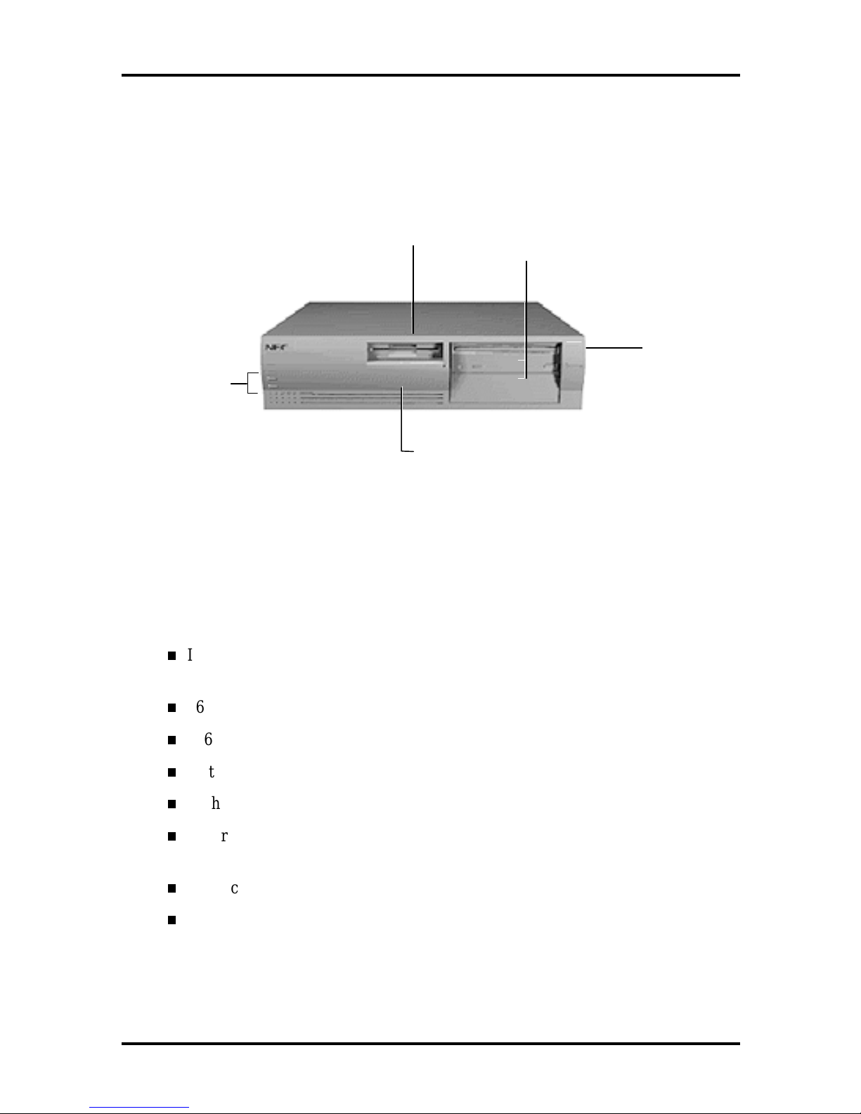
Figure 1-1 shows front panel features and locations of the accessible storage devices in a
desktop system. Multimedia systems come with a CD-ROM reader installed in the top
accessible device bay.
3 1/2-Inch
Diskette Drive
System Controls
and Lamps
3 1/2-Inch Internal
Hard Drive Bay
(behind panel)
5 1/4-Inch Accessible
Device Ba ys
Power Button
Figure 1-1 System Controls and Storage Device Bays
SYSTEM BOARD
Key features of the system board include the following:
Intel Pentium 100- or 133-MHz Pentium processor, depending on system
configuration
16-KB internal dual write-back cache integrated on the processor
256-KB synchronous pipeline burst secondary cache
system Setup program built into the BIOS
flash ROM for fast economical BIOS upgrades
integrated input/output (I/O) controller with keyboard, diskette drive, and hard
disk drive controllers. Supports two serial ports and a parallel port.
PCI local bus for fast data transfer
support for Intel OverDrive™ processors

Technical Information 1-3
8-MB or 16-MB EDO RAM (16 MB in multimedia configurations)
ships with 32-bit, non-parity, 60-ns single-inline memory modules (SIMMs)
RAM expandable up to 128 MB
1.2 GB hard disk
integrated graphics
Peripheral Component Interconnect (PCI) graphical user interface (GUI)
accelerator and motion video playback controller using SiS 6205
Graphics and Video Accelerator
standard 1-MB (two 512K x 16) video DRAM, expandable to 2 MB
standard 1-MB video DRAM supports resolutions of 640 x 480 with up to
16.8 million colors, 800 x 600 with up to 64K colors, 1024 x 768 with up to
256 K colors, and 1280 x 1024 with up to 16 colors
integrated sound (multimedia configurations only)
ESS ES1788 Sound Blaster compatible chip on system board
Yamaha OPL3 FM synthesis chip on system board
built-in 16-bit stereo and FM synthesis
Wavetable sound upgradeable
3D sound effects
two intelligent drive electronics (IDE) interface channels
one IDE/PCI channel (primary connector) used by the hard disk drive to
transfer data at the hard disk’s optimum rate
one standard IDE channel (secondary connector) for the CD-ROM reader
supports up to four IDE devices, two to each channel
power management for placing system in power save mode when idle for a
specified amount of time
3 1/2-inch, 1.44-MB diskette drive standard all configurations
four expansion slots: two ISA, one PCI, and one shared ISA/PCI connectors
external connectors for connecting the following external devices:
VGA-compatible monitor (standard, super, high-resolution VGA)
personal system/2 (PS/2®)-style mouse

1-4 Technical Information
y
y
PS/2-style keyboard
bidirectional Enhanced Parallel Port (EPP) and enhanced capabilities port
(ECP) are supported for a parallel printer
serial devices through two buffered 16C550 UART serial ports, each
supporting up to 19.2 KB per second
external speakers, microphone, and headphone connectors (multimedia
configurations only)
MIDI/joystick connector on the system board for installation of an optional
MIDI/joystick kit
Audio Wave upgrade connector on the system board for installation of an optional
Wave upgrade.
Table 1-2 lists the major chips on the system board. See Appendix A, Connector Pin
Assignments, for a list of the system board connectors. See Appendix B, System Board
Jumpers, for a description of board jumpers.
Table 1-2 System Board Chips
Chip Description
P54C (CPGA) 100/66-MHz Intel Pentium processor
133/66-MHz Intel Pentium processor
SiS PCI/ISA Chip Set
5511
5512
5513
SMC FDC37C665 Integrated Plug and Play Ultra I/O controller
SiS 6205 PCI GUI graphics controller
U24 128k x 8 Flash ROM
SiS 5513
Toshiba CR2032 Coin Cell Battery
ESS ES1788 Sound Chip
(multimedia systems only)
Yamaha OPL3-L Synthesizer Chip
(multimedia systems only)
stem controller
S
PCI/ISA cache memor
PCI local data buffer
PCI system I/O
Real-time clock
3 Volt Lithium CMOS battery (SMC 935)
Onboard PC sound system
Frequency modulated synthesizer
controller

Technical Information 1-5
Processor
The PowerMate Ve series of computers use the following Pentium processors:
PowerMate V100e — 100-MHz processor with internal speed of 100 MHz and
external speed of 66 MHz.
PowerMate V133e — 133-MHz processor with internal speed of 133 MHz and
external speed of 66 MHz.
Each processor has 16 KB of write-back primary cache and a math coprocessor. The 16 KB
primary cache provides 8 KB for instructions and 8 KB for data.
The processor is an advanced pipelined 32-bit addressing, 64-bit data processor designed to
optimize multitasking operating systems. The 64-bit registers and data paths support 64-bit
addresses and data types.
The processor is compatible with 8-, 16-, and 32-bit software written for the Intel386™,
Intel486™, and Pentium processors.
To accommodate future technologies and work requirements, the Pentium processor comes
in a 320-pin zero insertion force (ZIF) socket. The socket provides an upgrade path to the
next generation processor.
Secondary Cache
The system board contains 256 KB, 15-ns synchronous pipeline-burst secondary cache,
external to the processor.
Cache allows data to be sent or received from cache with one wait state burst. Cache
memory improves read performance by holding copies of code and data that are frequently
requested from the system memory by the processor. Cache memory is not considered part
of the expansion memory.
System and Video BIOS
The system and video BIOS are stored in a 1 MB (128 KB by 8) flash memory device
(Flash ROM). The system BIOS uses 64 KB, the video BIOS uses 32 KB, and 32 KB is
reserved. The system BIOS is capable of being shadowed and cached through the system’s
Setup utility (see Section 2 for Setup information). System BIOS is write protected and
automatically enabled.
The BIOS programs execute the Power-On Self-Test, initialize processor controllers, and
interact with the display, diskette drives, hard disks, communication devices, and
peripherals. The system BIOS also contains the Setup utility. The hardware setup default
copies the ROM BIOS into RAM (shadowing) for maximum performance.

1-6 Technical Information
The Flash ROM allows the system and video BIOS to be upgraded with the BIOS Update
utility, without removing the ROM (see Section 2 for further information on the BIOS
Update utility). The Flash ROM supports the reprogramming of the system BIOS and the
video BIOS.
The system memory map is shown in Table 1-3.
Table 1-3 System Memory Map
Memory Space Size Function
FFF80000-FFFFFFFF 512 KB BIOS ROM
04000000-07FFFFFF 64 MB L2 cache (Non-Cacheable with less than 512 KB
SRAM)
L1 cache (Cacheable)
01000000-03FFFFFF 48 MB Always cachable
00F00000-00FFFFFF 1 MB Optional memory space gap
00100000-00EFFFFF 14 MB Cachable
000F0000-000FFFFF 64 KB System BIOS (Shadowed in DRAM)
000C8000-000EFFFF 160 KB Expansion region (Shadowed in DRAM)
000C0000-000C7FFF 32 KB Video BIOS (Shadowed in DRAM)
000A0000-000BFFFF 128 KB Video Buffer (SMM space Non-Cacheable)
00080000-0009FFFF 128 KB Optional memory space gap (DOS Apps)
00000000-0007FFFF 512 KB DOS applications (No read/write protect) (Always
cacheable)
Power Management
Each system incorporates power management features that lower power consumption when
there is no activity detected from the keyboard, mouse, diskette drive, CD-ROM reader, or
hard disk drive after a predefined period of time. As soon as activity is detected the system
resumes where it left off.
With Power Management enabled (shipped enabled), the system automatically activates the
power-saving features and enters a suspend mode whenever inactivity is sensed.
I/O Addressing
The processor communicates with I/O devices by I/O mapping. The hexadecimal (hex)
addresses of I/O devices are listed in Table 1-4.

Technical Information 1-7
Table 1-4 I/O Address Map
Address (Hex) I/O Device Name
0000-000F DMA controller 1 (channel 0-3)
0020-0021 Interrupt controller 1
0040-0043 Timer 1
0048-004B Timer 2
0060 Keyboard controller data byte
0061 NMI status and speaker control
0064 Keyboard controller cmd/status byte
0070-007F Real-time clock, NMI mask
0080-008F DMA page registers
00A0-00A1 Interrupt controller 2
00C0-00DE DMA controller 2
00E0-00EF Reserved
00F0 Clear math coprocessor error
00F1 Reset math coprocessor
0F8-0FF Math coprocessor
170-177 Secondary IDE channel
1F0-1F7 Primary IDE channel
200, 202, 207 Game I/O
220-22F Sound port
238-23F Serial port 4 (used for remapping)
278-27F Parallel port 2
2B0-2DF Alternate EGA adapter
2F8-2FF Serial port 2
338-33F Serial port 3 (used for remapping)
370-375 Floppy cont. (secondary address)
376 Secondary IDE channel CMD port
377 Secondary IDE channel stat port

1-8 Technical Information
Table 1-4 I/O Address Map
Address (Hex) I/O Device Name
378-37F Parallel port 1
3B0-3BF Mono display & printer adapter
3C0-3CF EGA adapter
3D0-3DF CGA adapter
3F0-3F5, 3F7 Floppy controller (primary)
3F8-3FF Serial port 1
CF8-CFF PCI configuration space
System Memory
The non-multimedia V100e systems come standard with 8 MB of EDO memory: 640 KB of
base memory and 7 MB of extended memory. The non-multimedia V133e systems come
standard with either 8 MB or 16 MB of EDO memory. All multimedia configurations come
standard with 16 MB of EDO memory: 640 KB of base memory and 15 MB of extended
memory. System memory can be expanded up to 128 MB, using optional single in-line
memory modules (SIMMs) installed in SIMM sockets on the system board.
Four SIMM sockets are integrated on the system board. Non-multimedia systems ship with
two 4-MB SIMMs (8 MB total) installed in two sockets. The multimedia and V133e nonmultimedia configurations ship with two 8-MB SIMMs (16 MB total) installed in two
sockets.
The SIMM memory sockets accept 32-bit (non-parity) 4-, 8-, 16-, or 32-MB 70 ns SIMMs.
The SIMMs are 1 MB x 32 bit (4 MB), 2 MB x 32 bit (8 MB), 4 MB x 32 bit (16 MB), and
8 MB x 32 bit (32 MB). When the standard SIMMs are removed, four 32-MB SIMMs may
be installed for a total of 128 MB.
CAUTION:
SIMMs must match the tin metal
plating used on the system board SIMM sockets.
When adding SIMMs, use tin-plated SIMMs.
SIMMs install directly in the four sockets on the system board. The four sockets are
assigned as SIMM 1 through SIMM 4. For non-multimedia configurations, the two
standard 4 MB SIMMs are installed in SIMM 1 and SIMM 2. For multimedia
configurations, the two standard 8 MB SIMMs are installed in SIMM 1 and SIMM 2.
SIMMs must be installed in pairs of the same memory type and speed. Jumpers are not
required to set memory size or type as the system BIOS automatically detects the SIMMs.
SIMM banks 1 and 2 must always be filled for the system to operate. Table 1-5 shows the
SIMM memory upgrade path.

Technical Information 1-9
Table 1-5 SIMM Memory Upgrade Path
Total Memory SIMM 1 SIMM 2 SIMM 3 SIMM 4
8 MB 4 MB 4 MB Empty Empty
16 MB 4 MB 4 MB 4 MB 4 MB
16 MB 8 MB 8 MB Empty Empty
24 MB 4 MB 4 MB 8 MB 8 MB
24 MB 8 MB 8 MB 4 MB 4 MB
32 MB 8 MB 8 MB 8 MB 8 MB
32 MB 16 MB 16 MB Empty Empty
40 MB 4 MB 4 MB 16 MB 16 MB
40 MB 16 MB 16 MB 4 MB 4 MB
48 MB 8 MB 8 MB 16 MB 16 MB
48 MB 16 MB 16 MB 8 MB 8 MB
64 MB 16 MB 16 MB 16 MB 16 MB
64 MB 32 MB 32 MB Empty Empty
72 MB 4 MB 4 MB 32 MB 32 MB
72 MB 32 MB 32 MB 4 MB 4 MB
80 MB 8 MB 8 MB 32 MB 32 MB
80 MB 32 MB 32 MB 8 MB 8 MB
96 MB 16 MB 16 MB 32 MB 32 MB
96 MB 32 MB 32 MB 16 MB 16 MB
128 MB 32 MB 32 MB 32 MB 32 MB
Interrupt Controller
The interrupt controller operates as an interrupt manager for the entire AT system
environment. The controller accepts requests from peripherals, issues interrupt requests to
the processor, resolves interrupt priorities, and provides vectors for the processor to
determine which interrupt routine to execute. The interrupt controller has priority
assignment modes that can be reconfigured at any time during system operations.
The interrupt levels are described in Table 1-6. Interrupt-level assignments 0 through 15 are
in order of decreasing priority. See Section 2, Setup and Operation, for information on
changing the interrupts using Setup.

1-10 Technical Information
Table 1-6 Interrupt Level Assignments
Interrupt Priority Interrupt Device
IRQ00 System Timer
IRQ01 Keyboard
IRQ02 Audio (multimedia configurations only)
IRQ03 COM2
IRQ04 COM1
IRQ05 Audio (multimedia configurations only)
IRQ06 Diskette Drive Controller
IRQ07 Parallel Port LPT1
IRQ08 Clock/Calendar
IRQ09 Audio (multimedia configurations only)
IRQ10 Available
IRQ11 Available
IRQ12 PS/2 mouse
IRQ13 Coprocessor
IRQ13 Coprocessor
IRQ14 Primary IDE
IRQ15 Secondary IDE
Integrated Graphics
The system has an SiS 6205 PCI local bus motion video playback controller and graphics
accelerator integrated on the system board. State of the art techniques are used for
optimizing performance in computer graphic intensive applications and graphical user
interfaces (GUI).
The integrated graphics controller integrates a motion video controller, a high-performance
GUI accelerator, 24-bit high frequency DAC and clock generator, VESA®-compliant
feature connector, and 1 MB of fast 64-bit DRAM (upgradeable to 2 MB).
Motion Video Controller
The motion video controller integrates a powerful Windows® GUI engine and unique
motion video playback hardware for superior performance. The graphics engine includes an
on-chip color space converter to accelerate decompression and a hardware scaler to scale
continuously from native size up to full screen at full speed. The graphics engine delivers a
full screen, smooth display of motion video data up to 30 frames per second (fps). Support
includes MPEG-1 (multimedia systems only) and Video for Windows.

Technical Information 1-11
MPEG is a compression/decompression standard developed by the Motion Picture Experts
Group. MPEG produces full-screen 30 fps, broadcast-quality digital video. The video
controller architecture maximizes the motion video performance and removes bandwidth
bottlenecks to display multimedia data at its full speed.
Graphics Accelerator
The graphics accelerator is specifically designed for graphics-intensive operations, text and
color pixel amplification, and scrolling. The graphics accelerator provides 64-bit, ultra-high
performance for demanding True Color, High Color, and pseudocolor GUI and CAD
applications.
The accelerator minimizes bus traffic by off-loading the tasks normally performed by the
processor. The dedicated bit-block transfers (BitBLT) engine maximizes performance by
speeding the movement of large blocks of image data in video memory.
Video Memory
The system comes with 1 MB of on-board video DRAM, upgradeable to 2 MB. The
standard 1 MB DRAM consists of two 512 KB by 16 DRAM devices soldered to the
system board. The optional 1 MB of DRAM consists of two 512 KB by 16 modules that
install in two sockets on the system board.
With the standard 1 MB of video DRAM, the video hardware supports the following
resolutions, colors, and refresh rates:
1280 by 1024 pixels, 16 colors, 60 Hz
1024 by 768 pixels, 16/256 colors, 60 Hz, 70 Hz, 75 Hz, and 85 Hz
800 by 600 pixels, 16/256/64K colors, 56 Hz, 60 Hz, 72 Hz, 75 Hz, and 85 Hz
640 by 480 pixels, 16/256/64K/16 million colors, 60 Hz, 72 Hz, 75 Hz and 85 Hz
With 2 MB of video DRAM, the system supports the following additional resolutions,
colors, and refresh rates:
1280 by 1024 pixels, 256 colors, 60 Hz and 75 Hz
1024 by 768 pixels, 64K/16 million colors, 60 Hz, 70 Hz, 75 Hz and 85 Hz
800 by 600 pixels, 16 million colors, 56 Hz, 60 Hz, 72 Hz, 75 Hz, and 85 Hz
640 by 480 pixels, 16 million colors, 60 Hz, 72 Hz, 75 Hz, and 85 Hz.

1-12 Technical Information
ISA Bus
The system board uses the ISA bus for transferring data between the processor and I/O
peripherals and expansion boards. The ISA bus supports 16-bit data transfers and typically
operates at 8 MHz. ISA expansion slot connector pin assignments are provided in
Appendix A.
PCI Local Bus
The 32-bit PCI-bus is the primary I/O bus for the system. The PCI-bus is a highly-integrated
I/O interface that offers the highest performance local bus available for the Pentium
processor. The bus supports burst modes that send large chunks of data across the bus,
allowing fast displays of high-resolution images.
The PCI-bus operates at half the Pentium’s processor speed, and supports memory transfer
rates of up to 105 MB per second for reads and up to 120 MB per second for writes,
depending on processor configuration.
The high-bandwidth PCI-bus eliminates the data bottleneck found in traditional systems,
maintains maximum performance at high clock speeds, and provides a clear upgrade path to
future technologies.
The PCI bus contains two embedded PCI devices, the PCI local bus IDE interface and the
PCI video/graphics controller.
PCI expansion slot connector pin assignments are provided in Appendix A.
PCI Auto Configuration
The system comes with a PCI auto configuration utility that operates in conjunction with
the system’s Setup utility. The utilities automatically configure interrupts, DMA channels,
I/O space, and other parameters to allow addition of PCI boards with minimal user
intervention. (See Section 2 for Setup information.)
PCI/IDE Ports
The system board provides two high-performance PCI/IDE ports: a primary channel and a
secondary channel. Each port supports up to two devices for a total of four IDE devices.
The primary PCI/IDE port has an enhanced IDE interface which supports 11.1 MB per
second 32-bit wide data transfers on the high-performance PCI local bus. The installed hard
disk drive is connected to the primary PCI/IDE port. The installed CD-ROM reader
(multimedia only) is connected to the secondary PCI/IDE port.

Technical Information 1-13
Parallel Interface
The system has a 25-pin parallel bidirectional enhanced parallel port on the system board.
Port specifications conform to the IBM-PC standards. The port supports Enhanced
Capabilities Port (ECP) and Enhanced Parallel Port (EPP) modes for devices that require
ECP or EPP protocols. The protocols allow high-speed bidirectional transfer over a parallel
port and increase parallel port functionality by supporting more devices.
The BIOS has automatic ISA printer port sensing. If the BIOS detects an ISA printer port
mapped to the same address, the built-in printer port is disabled. The BIOS also sets the
first parallel interface port it finds as LPT1 and the second port it finds as LPT2. The
interrupt is selected to either IRQ5 or IRQ7 via Setup. Software selectable base addresses
are 3BCh, 378h, and 278h.
I/O addresses and interrupts for the parallel port are given in Table 1-7.
NOTE:
parallel port are not available for ISA parallel
ports.
Any interrupts used for the built-in
Table 1-7 Parallel Port Addressing and Interrupts
Starting I/O Address Interrupt Level Port
378 IRQ05 LPT1
278 IRQ05 LPT1 or LPT2
3BC IRQ07 LPT1 or LPT2
378 IRQ07 LPT1
278 IRQ07 LPT1 or LPT2
3BC IRQ07 LPT1 or LPT2
Parallel interface signals are output through the system board’s 25-pin, D-subconnector.
The connector is located at the rear of the system unit. Pin locations for the parallel
interface connector are given in Appendix A.
Serial Interface
The system has two 16C550 UART compatible serial ports (COM1 and COM2) integrated
on the I/O controller. The serial ports support the standard RS-232C interface (see
Table 1-8). The buffered high-speed serial ports supports transfer rates up to 19.2 KB.
These ports allow the installation of high-speed serial devices for faster data transfer rates.
1-14 Technical Information
I/O addresses and interrupt levels for the two channels are given in Table 1-8. The interrupt
level is selectable via Setup to either IRQ3 or IRQ4. Software selectable base addresses are
3F8h, 2F8h, 3E8h, and 2E8h.
NOTE: Any interrupts used for the built-in
serial ports are not available for ISA parallel
ports.
Table 1-8 Serial Port Addressing and Interrupts
Starting I/O Address Interrupt Level Port
3F8h IRQ04 COM1*
2F8h IRQ03 COM2
3E8h IRQ04 COM3
2E8h IRQ03 COM4
* Disabled if fax/modem installed
Serial interface specifications include:
Baud rate up to 19.2 KB per second
Word length - 5, 6, 7, or 8 bits
Stop bit - 1, 1.5, or 2 bits
Start bit - 1 bit
Parity bit - 1 bit (odd parity or even parity).
Serial interface signals are output through the system board’s 9-pin, D-subconnector. The
connectors are located at the rear of the system unit. Pin locations for the serial interface
connector are shown in Appendix A.
POWER SUPPLY
The power supply is mounted inside the system unit. It supplies power to the system board,
option boards, diskette drives, hard disks, keyboard, and mouse. A fan inside the power
supply provides system ventilation. The power supply supplies 145 watts of power.
Connector locations are in Appendix A.

Technical Information 1-15
DISKETTE DRIVE
Up to two diskette drives are supported. The installed 3 1/2-inch diskette drive is connected
by a single ribbon cable with two drive connectors. The diskette drive cable plugs directly
into the system board. Typically both diskette drives are terminated. Connector locations
are given in Appendix A.
HARD DISK DRIVE
Up to two IDE hard drives are supported. The system board has two IDE/PCI interface
connectors (primary and secondary) for connecting various storage devices such as hard
disk drives. Each connector supports up to two IDE devices.
The system ships with one internal 3 1/2-inch hard disk drive (1-inch high, thin-height)
installed behind the front panel. The drive cable plugs into the primary (fast) connector on
the system board.
KEYBOARD
The PS/2-style 104 key keyboard is standard equipment for the system. The keyboard
provides a numeric keypad, separate cursor control keys, and 12 function keys, capable of
up to 48 functions. Status lamps on the keyboard indicate: Num (Numeric) Lock, Caps
(Capital) Lock, and Scroll Lock key status. The keyboard’s six-pin connector plugs into the
rear of the system. The keyboard connector pin assignments are given in Appendix A.
MOUSE
A PS/2-compatible mouse is standard equipment for the system. The mouse has a selfcleaning mechanism that prevents a buildup of dust or lint around the mouse ball and
tracking mechanism. The mouse’s six-pin connector plugs into the rear of the system. The
mouse connector pin assignments are given in Appendix A.
MULTIMEDIA COMPONENTS
Systems configured for multimedia come with audio integrated on the system board, a
CD-ROM reader, a speaker set, and a microphone. The following briefly describes each.
Information on setting up and operating the speakers, microphone, and CD-ROM reader is
in Section 2, Setup and Operation.
Integrated Audio
Multimedia systems come with audio components integrated on the system board. Nonmultimedia systems do not have the audio components on the system board. The audio
components include an ESS ES1788 Sound Blaster-compatible chip, a Yamaha OPL3 FM
synthesizer chip, and an SRS Labs Sound Retrieval System®. The system’s integrated audio
features the following:

1-16 Technical Information
built-in 16-bit 128x oversampling Sigma-Delta Stereo Codec with 85dB S/N ratio
built-in five-channel 16/32 step MPC compatible stereo mixer with master volume
and sample rates up to 48 Hz stereo
dual DMA channel and built-in FIFOs for full duplex simultaneous playback and
record in 16-bit stereo
WaveBlaster upgradeable for Wavetable synthesis
3D sound effects
20 voice FM synthesis.
The integrated components are compatible with the Sound Blaster™ board and the
Microsoft® Windows Sound System™ board. The components work with the preinstalled
Voyetra multimedia sound software.
CD-ROM Reader
The eight-speed IDE CD-ROM reader is preinstalled as drive E on multimedia
configurations. The reader can be used to load programs from a CD or it can be used to
play audio CDs. The reader operates at different speeds depending on whether the CD
contains music or data. The reader is fully compatible with Kodak Multisession Photo
CDs™ and standard CDs. The reader is set as the master device on the secondary IDE/PCI
connector port.
Speakers
The multimedia systems come with 8 watt high-quality Goldtron stereo speakers, an AC
adapter, and connecting wires. The speaker set features treble, bass, and volume controls,
power on/off switch, power lamp, and a headphone jack. Volume is controlled from the
speaker or from the preinstalled sound system software. The speaker set connects to the
speaker line out jack on the back of the system.
Microphone
The Goldtron microphone that comes with the multimedia systems allows recording of
voice and sound into computer data files. The microphone connects to the MIC jack located
on the back of the system. The microphone works in conjunction with the audio software
shipped with the system.

Technical Information 1-17
PLUG AND PLAY
The system comes with a Plug and Play BIOS which supports Plug and Play technology.
Plug and Play eliminates complicated setup procedures for installing Plug and Play
expansion boards. With Plug and Play, adding a Plug and Play expansion board is done by
turning off the system, installing the board, and turning on the system. There are no jumpers
to set and no system resource conflicts to resolve. Plug and Play automatically configures
the board.
POWER MANAGEMENT
Each system is Energy Star compliant and comes with the power-saving features enabled. If
the keyboard, mouse, or drives are not used after 15 minutes, the screen goes blank and the
system goes into a partial power shutdown. A blinking power lamp indicates that the system
is in the power-saving mode. As soon as activity is detected, the system resumes where it
left off.
The system can be manually put into a Suspend power-saving mode by pressing the suspend
button. The Suspend mode provides the greatest power savings by putting the system in
maximum power shutdown. When the system goes into Suspend mode, it saves data and
system status and then shuts off power to all possible components. A blinking power lamp
indicates that the system is in the power-saving mode. As soon as activity is detected, the
system resumes where it left off.
The amount of inactive time is adjustable. Power management can also be disabled. Both
can be set through Setup.
DESKTOP MANAGEMENT INTERFACE
The Desktop Management Interface (DMI) is the standard interface used to manage system
components on the computer. DMI acts as a layer of abstraction between management
applications and managed components such as systems, network cards, and printers.
With DMI, a management application (such as Hewlett Packards Openview), provides a
simplified method to collect information from different vendors computers operating on the
network.
DMI is not a protocol but an interface that complements network protocols like the Simple
Network Management Protocol (SNMP).

1-18 Technical Information
DMI Components
The NEC DMI consists of two major functional components:
the Component Interface (CI) module
the NEC DMI Browser.
The CI module provides the instrumentation and interface between the BIOS and the DMI
Service Layer (SL). The DMI Browser displays and manages existing attributes in the
Management Information Format (MIF) database. The Desktop Management Task Force
(DMTF) provides the DOS Service Layer, Windows Service Layer, and MIF database
structure.
Manageable Components
Manageable components are hardware, software, and peripherals installed or attached to a
desktop computer or network server. These include hard disks, word processors, CDROMs, printers, operating systems, graphics boards, modems, etc. Manageable components
can come with the system or be added later. Each component supplies information to the
MIF database that contains the product’s pertinent management information.
Each product may or may not include an instrumentation module in order to provide realtime support.
CI Module
The Component Interface (CI) module is a Windows program that provides access to your
system and its components. It runs minimized in Windows and should only be canceled if
you are uninstalling DMI.
CI module is comprised of programs written by the component manufacturer to provide
real-time attribute values to the network Service Layer as requested.
DMI Browser
The NEC DMI Browser is a Windows application provided by NEC Technologies, Inc. The
Browser uses the Management Interface (MI) to provide access to MIF attributes and their
respective values. The Browser has the ability to set attributes and manage DMI
components.
The NEC Browser can only access the local MIF database. The Browser lets you access
MIF attributes according to the structure defined by the DMTF. It is not intended to be a
general PC management application. If a more comprehensive management application is
desired, use a product such as Intel’s LANDesk Manager™.
 Loading...