

Nec POWERMATE V user Manual

PROPRIETARY NOTICE AND LIABILITY DISCLAIMER
The info rmat ion disclos ed in t his do cument , inclu ding all designs and r elat ed materials, is
the valuable pr opert y of NEC Cor p oration (NEC) and/or its licensors. NEC and/or its licensors, as appropriate, r eserve all pat ent, copyright and other proprietary rights to t his document, including all design, manufacturing, reproduction, use, and sales rights t heret o, except
to the extent said rights are expressly granted to others.
The NEC product(s) discussed in this document are warr anted in accordance with the terms
of the Warranty Statement accompanying each product. However, actual performance of
each such product is dependent upo n fact ors such as system configuration, customer data,
and operator control. Since implementation by customers of each product may vary, the
suitability of specific product configurations and applicat ions must be determined by the
customer and is not warranted by NEC.
To allow for design and specification impro vement s, t he information in this do cument is
subject to change at any time, without no tice. Reproduct ion of this document or po rtions
thereof without prior written approval of NEC is prohibited.
MultiSync and PowerMate are U.S. registered trademarks of NEC Technologies, Inc.
FastFacts is a U.S. trademark of NEC Technologies, Inc.
All other product, brand, or trade names used in this publication are the trademarks or registered
trademarks of their respective trademark owners.
First Printing — March 1996
Copyright 1996 Copyright 1996
NEC Technologies, Inc. NEC Corporation
1414 Massachusetts Avenue 7-1 Shiba 5-Chome, Minato-Ku
Boxborough, MA 01719 Tokyo 108-01, Japan
All Rights Reserved All Rights Reserved

Contents
Preface......................................................................................................................... xv
Abbreviations............................................................................................................... xvii
Section 1 Technical Information
Desktop System Chassis............................................................................................... 1-3
Minitower System Chassis ........................................................................................... 1-4
System Board .............................................................................................................. 1-5
Processor.............................................................................................................. 1-7
Secondary Cache .................................................................................................. 1-8
System and Video BIOS ....................................................................................... 1-8
System Memory.................................................................................................... 1-9
Integrated Graphics............................................................................................... 1-11
iii
Motion Video Controller............................................................................... 1-11
Graphics Accelerator..................................................................................... 1-11
Video Memory.............................................................................................. 1-11
Interrupt Controller............................................................................................... 1-12
I/O Addressing...................................................................................................... 1-14
ISA Bus................................................................................................................ 1-15
PCI Local Bus ...................................................................................................... 1-15
PCI Auto Configuration........................................................................................ 1-15
PCI/IDE Ports ...................................................................................................... 1-15
Parallel Interface................................................................................................... 1-16
Serial Interface...................................................................................................... 1-16
Infrared Interface.................................................................................................. 1-17
Power Supply .............................................................................................................. 1-18
Diskette Drive.............................................................................................................. 1-18
Hard Disk Drive........................................................................................................... 1-18
Keyboard..................................................................................................................... 1-19
Mouse ......................................................................................................................... 1-19
Multimedia Components.............................................................................................. 1-19
Integrated Audio................................................................................................... 1-19
CD-ROM Reader.................................................................................................. 1-20
Speakers............................................................................................................... 1-20
Microphone .......................................................................................................... 1-20

iv Contents
Network Board............................................................................................................ 1-20
Plug and Play............................................................................................................... 1-20
Power Management..................................................................................................... 1-21
Desktop Management Interface.................................................................................... 1-21
DMI Components................................................................................................. 1-21
Manageable Components ...................................................................................... 1-22
CI Module ............................................................................................................ 1-22
DMI Browser ....................................................................................................... 1-22
Usage ................................................................................................................... 1-23
DMI Troubleshooting ........................................................................................... 1-24
Specifications............................................................................................................... 1-25
Section 2 Setup and Operation
Unpacking and Repacking............................................................................................ 2-1
Setup........................................................................................................................... 2-1
Desktop Setup...................................................................................................... 2-1
Minitower Setup................................................................................................... 2-6
CD-ROM Reader......................................................................................................... 2-11
System Configuration................................................................................................... 2-12
Setup Utility.......................................................................................................... 2-12
How to Start Setup............................................................................................... 2-13
How to Use Setup................................................................................................. 2-14
Menu Bar...................................................................................................... 2-14
Legend Bar................................................................................................... 2-15
Field Help Window ....................................................................................... 2-16
General Help Window................................................................................... 2-16
Main Menu Options ...................................................................................... 2-16
IDE Adapters................................................................................................ 2-17
Memory Cache.............................................................................................. 2-19
Memory Shadow........................................................................................... 2-19
Boot Options ................................................................................................ 2-20
Numlock....................................................................................................... 2-20
Advanced Menu.................................................................................................... 2-21
Integrated Peripherals Menu.......................................................................... 2-21
Security Menu....................................................................................................... 2-23
Power Menu......................................................................................................... 2-24
Boot Menu ........................................................................................................... 2-25

Contents v
Exit Menu............................................................................................................. 2-26
Save Changes & Exit .................................................................................... 2-26
Discard Changes & Exit................................................................................ 2-26
Get Default Values........................................................................................ 2-27
Load Previous Values ................................................................................... 2-27
Save Changes................................................................................................ 2-27
BIOS Update Utility .................................................................................................... 2-27
NEC Bulletin Board Service.................................................................................. 2-28
Using the BIOS Update Utility.............................................................................. 2-29
Section 3 Option Installation
General Rules for Installing Options............................................................................. 3-1
Precautions.................................................................................................................. 3-2
Removing the System Unit Cover ................................................................................ 3-3
Removing the Desktop Cover ............................................................................... 3-3
Removing the Minitower Cover ............................................................................ 3-5
Expansion Boards........................................................................................................ 3-6
Expansion Slot Locations...................................................................................... 3-7
Expansion Board Installation................................................................................. 3-8
Inside Slot Expansion Board Installation ....................................................... 3-11
System Board Options ................................................................................................. 3-12
SIMM Upgrade..................................................................................................... 3-13
Checking System Memory............................................................................. 3-13
SIMM Removal ............................................................................................ 3-15
SIMM Installation......................................................................................... 3-16
Video Upgrade ..................................................................................................... 3-17
Processor Upgrade................................................................................................ 3-18
Processor Removal ....................................................................................... 3-18
Processor Installation.................................................................................... 3-19
MIDI/Joystick Upgrade ............................................................................................... 3-19
Data Storage Devices................................................................................................... 3-21
Device Slots.......................................................................................................... 3-21
Device Preparation................................................................................................ 3-23
Device Cables....................................................................................................... 3-23
Diskette Drive Signal Cable........................................................................... 3-24
IDE Signal Cables......................................................................................... 3-24
System Power Cables.................................................................................... 3-25

vi Contents
Device Cabling...................................................................................................... 3-26
Cabling an IDE Device.................................................................................. 3-26
Cabling a Diskette Drive ............................................................................... 3-27
Desktop Storage Device Installation...................................................................... 3-27
Removing the Desktop 3 1/2-Inch Drive Bracket .......................................... 3-28
Installing the Desktop 3 1/2-Inch Drive......................................................... 3-28
Removing the Desktop Front Panel............................................................... 3-29
Installing the Desktop 5 1/4-Inch Device....................................................... 3-31
Replacing the Desktop Front Panel................................................................ 3-32
Replacing the Desktop 3 1/2-Inch Drive Bracket........................................... 3-32
Minitower Storage Device Installation................................................................... 3-33
Installing the 3 1/2-Inch Drive into the Minitower Internal Front Slot............ 3-34
Installing a 3 1/2-Inch Drive into a Minitower Rear Slot................................ 3-34
Removing the Minitower Front Panel............................................................ 3-36
Installing the Minitower 5 1/4-Inch Device.................................................... 3-38
Replacing the Minitower Front Panel............................................................. 3-40
Adding External Options.............................................................................................. 3-41
Parallel Printer ...................................................................................................... 3-41
RS-232C Device Connection................................................................................. 3-42
Section 4 Maintenance and Troubleshooting
Maintenance ................................................................................................................ 4-1
System Cleaning.................................................................................................... 4-2
Keyboard Cleaning................................................................................................ 4-2
Mouse Cleaning.................................................................................................... 4-3
Troubleshooting........................................................................................................... 4-4
Diagnosing and Solving Problems ......................................................................... 4-4
CMOS Battery Replacement................................................................................. 4-8
Section 5 Desktop Repair
Disassembly and Reassembly........................................................................................ 5-1
System Unit Cover Removal ................................................................................. 5-2
Expansion Board Removal.................................................................................... 5-3
PCI/ISA Backboard Removal................................................................................ 5-5
3 1/2-inch Diskette and Hard Disk Drive Removal ................................................ 5-5
Front Panel Assembly Removal............................................................................. 5-7
Blank Panel Removal ............................................................................................ 5-8

Contents vii
Speaker Assembly Removal .................................................................................. 5-8
SIMM Removal.................................................................................................... 5-9
5 1/4-Inch Device Removal................................................................................... 5-10
Power Supply Removal......................................................................................... 5-11
System Board Removal......................................................................................... 5-13
Illustrated Parts Breakdown.................................................................................. 5-14
Section 6 Minitower Repair
Disassembly and Reassembly........................................................................................ 6-1
System Unit Cover Removal ................................................................................. 6-2
Expansion Board Removal.................................................................................... 6-4
SIMM Removal.................................................................................................... 6-4
Front 3 1/2-Inch Drive Removal............................................................................ 6-6
3 1/2-inch Diskette Drive Removal........................................................................ 6-7
Front Panel Assembly Removal............................................................................. 6-7
Blank Panel and Metal Cover Plate Removal......................................................... 6-8
5 1/4-Inch Device Removal................................................................................... 6-9
Rear 3 1/2-Inch Drive Removal............................................................................. 6-11
Card Guide/Fan Bracket Removal......................................................................... 6-12
Speaker Assembly Removal .................................................................................. 6-13
Power Supply Removal......................................................................................... 6-14
PCI/ISA Backboard Removal................................................................................ 6-15
System Board Removal......................................................................................... 6-15
Illustrated Parts Breakdown.................................................................................. 6-17
Appendix A Connector Pin Assignments
CD Audio Connector Pin Assignments......................................................................... A-3
Serial Interface Connectors.......................................................................................... A-3
Parallel Interface Connector......................................................................................... A-4
VGA Interface Connector Pin Assignments.................................................................. A-5
Speaker Connector Pin Assignments ............................................................................ A-5
Power Supply Connector ............................................................................................. A-6
Keyboard and Mouse Connectors................................................................................. A-6
IRDA Connector.......................................................................................................... A-7
Suspend Button Connector .......................................................................................... A-7
Fan Connector............................................................................................................. A-7
Diskette Drive Interface Pin Assignments..................................................................... A-8

viii Contents
IDE Interface Connectors ............................................................................................ A-9
SIMM Sockets............................................................................................................. A-10
ISA/PCI-Bus Backboard Connector Pin Assignments...................................................A-11
ISA Expansion Bus Connector Pin Assignments...........................................................A-13
Appendix B System Board Jumpers
Jumper Locations......................................................................................................... B-1
Changing Processor Jumper Settings............................................................................ B-2
Changing the Password................................................................................................ B-4
Clearing CMOS........................................................................................................... B-5
Appendix C Hard Disk Drive Specifications and Jumper Settings
Hard Disk Drive Specifications .................................................................................... C-1
540-MB Hard Disk Drive Jumper Settings................................................................... C-3
850-MB Hard Disk Drive Jumper Settings................................................................... C-4
1.2-GB Hard Disk Drive Jumper Settings..................................................................... C-5
1.6-GB Hard Disk Drive Jumper Settings..................................................................... C-6
Appendix D CD-ROM Reader Specifications and Jumper Settings
CD-ROM Reader Specifications................................................................................... D-1
CD-ROM Reader Connectors and Jumper Settings ...................................................... D-2
List of Figures
1-1 Desktop System Controls and Storage Device Slots....................................... 1-3
1-2 Minitower System Controls and Storage Device Slots.................................... 1-4
2-1 Desktop Voltage Selector Switch................................................................... 2-2
2-2 Desktop Peripheral Connections..................................................................... 2-2
2-3 Desktop Network Board Connections............................................................ 2-3
2-4 Assembling the Microphone Holder................................................................ 2-4
2-5 Connecting the Microphone ........................................................................... 2-4
2-6 Desktop Power Button, Lamps, and Suspend Button ..................................... 2-5
2-7 Minitower Voltage Selector Switch................................................................ 2-6
2-8 Minitower Peripheral Connections.................................................................. 2-7
2-9 Minitower Network Board Connections......................................................... 2-7
2-10 Assembling the Microphone Holder................................................................ 2-8

Contents ix
2-11 Connecting the Microphone ........................................................................... 2-9
2-12 Minitower Power Button, Lamps, and Suspend Button .................................. 2-10
2-13 Typical CD-ROM Reader Controls and Indicators.......................................... 2-11
3-1 Removing Desktop Cover Screws.................................................................. 3-3
3-2 Releasing the Desktop Cover ......................................................................... 3-4
3-3 Removing Minitower Cover Screws............................................................... 3-5
3-4 Releasing the Cover ....................................................................................... 3-6
3-5 Locating Desktop Expansion Slots................................................................. 3-7
3-6 Locating Minitower Expansion Slots.............................................................. 3-8
3-7 Removing a Slot Cover in the Desktop........................................................... 3-9
3-8 Removing a Slot Cover in the Minitower........................................................ 3-9
3-9 Inserting the Board in the Desktop................................................................. 3-10
3-10 Inserting the Board in the Minitower.............................................................. 3-10
3-11 Removing the Slot Cover Support Screws...................................................... 3-11
3-12 Attaching the Slot Cover Support .................................................................. 3-12
3-13 System Board Upgrade Sockets and Connectors............................................ 3-12
3-14 Removing a SIMM......................................................................................... 3-15
3-15 Inserting the SIMM........................................................................................ 3-16
3-16 Aligning the Video DRAM Module with the Socket....................................... 3-17
3-17 Removing the Metal MIDI/Joystick Punch-Out in the Desktop....................... 3-20
3-18 Removing the Metal MIDI/Joystick Punch-Out in the Minitower.................... 3-21
3-19 Locating Device Slots in the Desktop............................................................. 3-22
3-20 Locating Device Slots in the Minitower.......................................................... 3-22
3-21 System Board Cable Connectors.................................................................... 3-23
3-22 Optional Diskette Drive Connector ................................................................ 3-24
3-23 Optional IDE Cable Connector....................................................................... 3-25
3-24 Power Cable Connectors................................................................................ 3-25
3-25 Connecting IDE Device Cables ...................................................................... 3-26
3-26 Connecting 1.2-MB Diskette Drive Cables..................................................... 3-27
3-27 Removing the 3 1/2-Inch Drive Bracket ......................................................... 3-28
3-28 Securing a 3 1/2-Inch Drive............................................................................ 3-29
3-29 Removing the Front Panel.............................................................................. 3-30
3-30 Locating the Blank Panel Tabs....................................................................... 3-30
3-31 Securing the Device ....................................................................................... 3-31
3-32 Aligning the Desktop Front Panel................................................................... 3-32
3-33 Securing the 3 1/2-Inch Drive Bracket............................................................ 3-33

x Contents
3-34 Left Side Drive Screws .................................................................................. 3-34
3-35 Removing the Drive Bracket Screws.............................................................. 3-35
3-36 Securing the Drive to the Bracket................................................................... 3-35
3-37 Removing the Front Panel.............................................................................. 3-36
3-38 Locating the Blank Panel Tabs....................................................................... 3-37
3-39 Locating the Slot Cover................................................................................. 3-37
3-40 Attaching the Device Rails ............................................................................. 3-38
3-41 Front and Left Side Device Screws................................................................. 3-39
3-42 Right Side Device Screws .............................................................................. 3-39
3-43 Aligning the Minitower Front Panel................................................................ 3-40
3-44 Connecting a Printer Cable to the Desktop..................................................... 3-41
3-45 Connecting a Printer Cable to the Minitower.................................................. 3-42
3-46 Connecting an RS-232C Cable to the Desktop ............................................... 3-43
3-47 Connecting an RS-232C Cable to the Minitower ............................................ 3-43
4-1 Removing the Mouse Ball Cover.................................................................... 4-3
4-2 Battery Socket Location................................................................................. 4-8
4-3 Battery Removal ............................................................................................ 4-9
4-4 RTC Chip Removal........................................................................................ 4-9
5-1 System Unit Cover Screws............................................................................. 5-3
5-2 Removing the System Unit Cover................................................................... 5-3
5-3 Expansion Slot Screw .................................................................................... 5-4
5-4 Inside Expansion Slot Screw.......................................................................... 5-4
5-5 PCI/ISA Backboard Screws........................................................................... 5-5
5-6 3 1/2-Inch Drive Bracket................................................................................ 5-6
5-7 3 1/2-Inch Diskette and Hard Disk Drive Screws............................................ 5-6
5-8 Front Panel Tabs............................................................................................ 5-7
5-9 Blank Panel Tabs ........................................................................................... 5-8
5-10 Internal Speaker............................................................................................. 5-9
5-11 SIMM Socket................................................................................................ 5-9
5-12 5 1/4-Inch Device Screws............................................................................... 5-10
5-13 Power Button Screws .................................................................................... 5-11
5-14 Power Supply Screws .................................................................................... 5-12
5-15 System Board Connectors and Screws ........................................................... 5-13
5-16 PowerMate V Desktop Illustrated Parts Breakdown....................................... 5-16

Contents xi
6-1 Removing Minitower Cover Screws............................................................... 6-3
6-2 Releasing the Cover ....................................................................................... 6-3
6-3 Removing the Screw in the Minitower............................................................ 6-4
6-4 System Board Upgrade SIMM Sockets.......................................................... 6-5
6-5 Removing a SIMM......................................................................................... 6-5
6-6 Right Side Front Internal Drive Screws.......................................................... 6-6
6-7 Left Side Front Internal Drive Screws ............................................................ 6-6
6-8 Diskette Drive Bracket Screws....................................................................... 6-7
6-9 Removing the Front Panel.............................................................................. 6-8
6-10 Locating the Blank Panel Tabs....................................................................... 6-8
6-11 Locating and Removing the Slot Covers......................................................... 6-9
6-12 Front and Left Side Device Screws................................................................. 6-10
6-13 Right Side Device Screws .............................................................................. 6-10
6-14 Removing the Device Rails............................................................................. 6-11
6-15 Removing the Drive Bracket Screws.............................................................. 6-11
6-16 Securing the Drive to the Bracket................................................................... 6-12
6-17 Removing the Card Guide/Fan Bracket Assembly........................................... 6-13
6-18 Speaker.......................................................................................................... 6-13
6-19 Power Supply Screws .................................................................................... 6-14
6-20 PCI/ISA Backboard....................................................................................... 6-15
6-21 System Board Removal.................................................................................. 6-16
6-22 PowerMate V Minitower Illustrated Parts Breakdown.................................... 6-19
A-1 System Board Layout..................................................................................... A-1
A-2 Detailed Front System Board Connectors....................................................... A-2
A-3 Power Supply Connector Pin Assignments..................................................... A-6
B-1 System Board Jumper Locations .................................................................... B-1
B-2 Processor Settings with One BF Jumper......................................................... B-3
B-3 Processor Settings with Two BF Jumpers (BF0 and BF1) .............................. B-4
C-1 Quantum 540-MB Jumper Settings ................................................................ C-3
C-2 Western Digital 850-MB Jumper Settings....................................................... C-4
C-3 Conner 1.2- and 1.6-GB Jumper Settings ....................................................... C-5

xii Contents
List of Tables
1-1 First Release of System Configurations........................................................... 1-1
1-2 Second Release of System Configurations...................................................... 1-2
1-3 System Board Chips....................................................................................... 1-7
1-4 System Memory Map..................................................................................... 1-9
1-5 SIMM Memory Upgrade Path........................................................................ 1-10
1-6 Interrupt Assignments .................................................................................... 1-13
1-7 I/O Address Map ........................................................................................... 1-14
1-8 Parallel Port Addressing and Interrupts .......................................................... 1-16
1-9 Serial Port Addressing and Interrupts............................................................. 1-17
1-10 Specifications................................................................................................. 1-25
2-1 Setup Key Functions ...................................................................................... 2-15
2-2 Main Menu Parameters .................................................................................. 2-17
2-3 IDE Hard Disk Parameters............................................................................. 2-18
2-4 Memory Cache Parameters............................................................................. 2-19
2-5 Boot Parameters ............................................................................................ 2-20
2-6 Numlock Parameters...................................................................................... 2-20
2-7 Advanced Menu Parameters........................................................................... 2-21
2-8 Integrated Peripherals Parameters .................................................................. 2-22
2-9 System Security Options ................................................................................ 2-23
2-10 Power Management Parameters ..................................................................... 2-25
3-1 Recommended Memory Upgrade Path ........................................................... 3-14
4-1 NEC Service and Information Telephone Numbers......................................... 4-1
4-2 Problems and Solutions.................................................................................. 4-4
5-1 PowerMate V Desktop Disassembly Sequence............................................... 5-1
5-2 PowerMate V Desktop Field-Replaceable Parts List....................................... 5-14
5-3 PowerMate V Desktop Options ..................................................................... 5-17
5-4 PowerMate V Desktop Documentation and Packaging................................... 5-17
6-1 PowerMate V Minitower Disassembly Sequence............................................ 6-1
6-2 PowerMate V Minitower Field-Replaceable Parts List.................................... 6-17
6-3 PowerMate V Minitower Options .................................................................. 6-20
6-4 PowerMate V Minitower Documentation and Packaging................................ 6-20

Contents xiii
A-1 System Board Connectors.............................................................................. A-2
A-2 CD Audio in Connector ................................................................................. A-3
A-3 Serial Port Connector Pin Assignments .......................................................... A-3
A-4 Parallel Port Connector Pin Assignments........................................................ A-4
A-5 VGA Interface Connector Pin Assignments.................................................... A-5
A-6 Speaker Connector Pin Assignments .............................................................. A-5
A-7 Keyboard and Mouse Connector Pin Assignments.......................................... A-6
A-8 IRDA Connector Pin Assignments ................................................................. A-7
A-9 Suspend Connector Pin Assignments.............................................................. A-7
A-10 Fan Connector Pin Assignments..................................................................... A-7
A-11 Diskette Drive Connector Pin Assignments .................................................... A-8
A-12 IDE Connector Pin Assignments .................................................................... A-9
A-13 SIMM Socket Pin Assignments...................................................................... A-10
A-14 ISA/PCI Backboard Connector Pin Assignments............................................A-11
A-15 ISA Expansion Slot Pin Assignments..............................................................A-13
C-1 Hard Disk Drive Specifications....................................................................... C-1
D-1 CD-ROM Reader Specifications..................................................................... D-1

xv
Preface
This service and reference manual contains the technical information necessary to set up,
maintain, troubleshoot, and repair the NEC PowerMate V series computer systems. It also
provides hardware and interface information for users who need an overview of the
computer system design. The manual is written for NEC-trained customer engineers, system
analysts, service center personnel, and dealers.
The manual is organized as follows:
Section 1, Technical Information, provides an overview of the computer features,
hardware design, interface ports, internal devices and system unit specifications.
Section 2, Setup and Operation, gives general setup and operation information. Included
is a description of the system Setup utility and the factory default configuration settings. A
procedure is provided for logging onto the NEC Bulletin Board and obtaining the latest
Flash ROM BIOS.
Section 3, Options, provides safety precautions and installation procedures for installing
options.
Section 4, Maintenance and Troubleshooting, includes a list of NEC service information
and telephone numbers that provide access to the NEC Bulletin Board System (BBS),
FastFacts, and Technical Information Bulletins. Recommended maintenance information
and solutions to possible problems that may occur, are also provided.
Section 5, Desktop Repair, provides desktop disassembly and reassembly procedures
along with an illustrated parts breakdown. NEC service and spare parts ordering
information is also provided.
Section 6, Minitower Repair, provides minitower disassembly and reassembly procedures
along with an illustrated parts breakdown. NEC service and spare parts ordering
information is also provided.
Appendix A, Connector Pin Assignments, provides a list of the system board’s internal
connector pin assignments and a list of external pin assignments for the keyboard/mouse,
serial port, parallel port, and video port.
Appendix B, System Board Jumpers, provides jumper information for configuring the
system for a particular requirement.
Appendix C, Hard Disk Drive Specifications and Jumper Settings, provides
specifications and jumper settings for the hard disk drives that ship with the PowerMate V
series systems.
Appendix D, CD-ROM Reader Specifications and Jumper Settings, provides
specifications and jumper settings for the CD-ROM readers that ship with the PowerMate V
series systems.

xvi Preface

Abbreviations
xvii
A ampere
AC alternating current
AT advanced technology (IBM PC)
BBS Bulletin Board System
BCD binary-coded decimal
BCU BIOS Customized Utility
BIOS basic input/output system
bit binary digit
BUU BIOS Upgrade Utility
bpi bits per inch
bps bits per second
C capacitance
C centigrade
Cache high-speed buffer storage
CAM constantly addressable memory
CAS column address strobe
CD-ROM compact disk-ROM
CGA Color Graphics Adapter
CGB Color Graphics Board
CH channel
clk clock
cm centimeter
CMOS complementary metal oxide
semiconductor
COM communication
CONT contrast
CPGA ceramic pin grid array
CPU central processing unit
DAC digital-to-analog converter
DACK DMA acknowledge
db decibels
DC direct current
DIP dual in-line package
DMA direct memory access
DMAC DMA controller
DOS disk operating system
DRAM dynamic RAM
ECC error checking and correction
ECP enhanced capabilities port (ECP)
EGA Enhanced Graphics Adapter
EPP Enhanced Parallel Port
EPROM erasable and programmable ROM
EVGA Enhanced Video Graphics Array
F Fahrenheit
FAX facsimile transmission
FCC Federal Communications Commission
FG frame ground
FIFO first-in/first-out
FM frequency modulation
FRU field-replaceable unit
GB gigabyte
GND ground
HEX hexadecimal
HGA Hercules Graphics Adapter
Hz hertz
IC integrated circuit
ID identification
IDE intelligent device electronics
in. inch
IPB illustrated parts breakdown
ISA Industry Standard Architecture
I/O input/output
IPC integrated peripheral controller
ips inches per second
IR infrared
IRQ interrupt request
K kilo (1024)
k kilo (1000)
KB kilobyte
kg kilogram
kHz kilohertz
lb pound
LED light-emitting diode
M mega

xviii Abbreviations
mA milliamps
max maximum
MB megabyte
MDA Monochrome Display Adapter
MFM modified frequency modulation
MHz megahertz
MIC microphone
MIDI musical instrument device interface
MPC multimedia PC
mm millimeter
MPEG Motion Picture Experts Group
ms millisecond
NASC National Authorized Service Center
NC not connected
NMI Non-maskable Interrupt
ns nanosecond
NSRC National Service Response Center
PAL programmable array logic
PC personal computer
PCI Peripheral Component Interconnect
PDA personal digital assistant
PFP plastic flat package
PIO parallel input/output
pixel picture element
PROM programmable ROM
RAM random-access memory
RAMDAC RAM digital-to-analog converter
RGB red green blue
RGBI red green blue intensity
ROM read-only memory
rpm revolutions per minute
R read
RTC real-time clock
R/W read/write
S slave
SCSI Small Computer System Interface
SG signal ground
SIMM single inline memory module
SVGA Super Video Graphics Array
SW switch
TAC Technical Assistance Center
TSC Technical Support Center
TTL transistor/transistor logic
tpi tracks per inch
V volt
Vac volts, alernating current
Vdc volts, direct current
VESA video electronics standards
association
VGA Video Graphics Array
VRAM video RAM
W watt
W write

Section 1
y
y
y
y
y
Technical Information
The PowerMate® V Series of desktop and minitower systems come standard with an Intel
Pentium™ processor, a 3 1/2-inch 1.44 megabyte (MB) diskette drive, 256 kilobyte (KB)
secondary cache, 8- or 16-MB random access memory (RAM), and 1 MB of video dynamic
random access memory (DRAM).
The first release of the PowerMate V system configurations are listed in Table 1-1. See
Table 1-2 for the PowerMate V configurations released in March of 1996.
Table 1-1 First Release of System Configurations
Configurations
Diskless 3 1/2-Inch diskette
Hard disk system 3 1/2-inch diskette drive
Network-read
system
Multimedia 3 1/2-inch diskette drive
PowerMate V75
(75 MHz)
drive onl
8 MB of RAM
540 MB hard disk
with 8 MB of RAM
or
1.2 GB hard disk
with 16 MB of RAM
3 1/2-inch diskette drive
1.2 GB hard disk
Network board
8 MB of RAM
1.2 GB hard disk
quad-speed CD-ROM
reader
stem board w/audio
S
16 MB of RAM
Speakers
Microphone
PowerMate V90
(90 MHz)
Not available Not available
3 1/2-inch diskette drive
540 MB hard disk
with 8 MB of RAM
or
1.2 GB hard disk
with 16 MB of RAM
3 1/2-inch diskette drive
1.2 GB hard disk
Network board
8 MB of RAM
3 1/2-inch diskette drive
1.2 GB hard disk
quad-speed CD-ROM
reader
stem board w/audio
S
16 MB of RAM
Speakers
Microphone
PowerMate V100
(100 MHz)
3 1/2-inch diskette drive
540 MB hard disk
with 8 MB of RAM
or
1.2 GB hard disk
with 16 MB of RAM
3 1/2-inch diskette drive
1.2 GB hard disk
Network board
8 MB of RAM
3 1/2-inch diskette drive
1.2 GB hard disk
quad-speed CD-ROM
reader
stem board w/audio
S
16 MB of RAM
Speakers
Microphone

1-2 Technical Information
y
y
y
y
Table 1-2 Second Release of System Configurations
Configurations
Hard disk system 3 1/2-inch diskette drive
Network-read
system
(desktops only)
Multimedia 3 1/2-inch diskette drive
PowerMate V75
(75 MHz)
850 MB hard disk
with 8 MB of RAM
or
1.6 MB hard disk
with 16 MB of RAM
3 1/2-inch diskette drive
850 MB hard disk
Network board
8 MB of RAM
1.6 GB hard disk
six-speed CD-ROM
reader
stem board w/audio
S
16 MB of RAM
7 W Speakers
Microphone
PowerMate V100
(100 MHz)
3 1/2-inch diskette drive
850 MB hard disk
with 8 MB of RAM
or
1.6 MB hard disk
with 16 MB of RAM
3 1/2-inch diskette drive
850 MB hard disk
Network board
8 MB of RAM
3 1/2-inch diskette drive
1.6 GB hard disk
six-speed CD-ROM
reader
stem board w/audio
S
16 MB of RAM
7 W Speakers
Microphone
PowerMate V133
(133 MHz)
3 1/2-inch diskette drive
850 MB hard disk
with 8 MB of RAM
or
1.6 MB hard disk
with 16 MB of RAM
3 1/2-inch diskette drive
850 MB hard disk
Network board
8 MB of RAM
3 1/2-inch diskette drive
1.6 GB hard disk
six-speed CD-ROM
reader
stem board w/audio
S
16 MB of RAM
8 W Speakers
Microphone
Each system incorporates power management features, and has factory installed software to
enhance the hardware features. Systems come with a dual operating system requiring that
either Microsoft® Windows for Workgroups™ or Windows 95™ be selected when the
system is first powered on.
The following paragraphs give an overview of the desktop and minitower systems.
Differences between systems are noted as they occur.
Technical Information 1-3
DESKTOP SYSTEM CHASSIS
The desktop chassis provides an enclosure for the system board, power supply, four
expansion slots, a five-connector PCI/ISA backboard, and four storage device slots. The
expansion slots include two 8-/16-bit ISA slots, one dedicated 32-bit PCI slot, and one
shared PCI/ISA (32-bit PCI or 8-/16-bit ISA) slot. For network-ready configurations, one
slot has a network board installed and the remaining slots are open.
The four storage device slots accommodate up to three accessible devices and one internal
hard disk drive device. The accessible devices include the standard one-inch high 3 1/2-inch
1.44-MB diskette drive and up to two 1.6-inch high 5 1/4-inch storage devices. The nonmultimedia hard disk systems ship with an accessible 3 1/2-inch diskette drive and an
internal 3 1/2-inch hard disk drive, leaving two accessible 5 1/4-inch storage device slots
available for optional devices. The multimedia systems ship with an accessible 3 1/2-inch
diskette drive, an internal 3 1/2-inch hard disk drive, and an accessible 5 1/4-inch CD-ROM
reader, leaving one accessible 5 1/4-inch storage device slot available for an optional device.
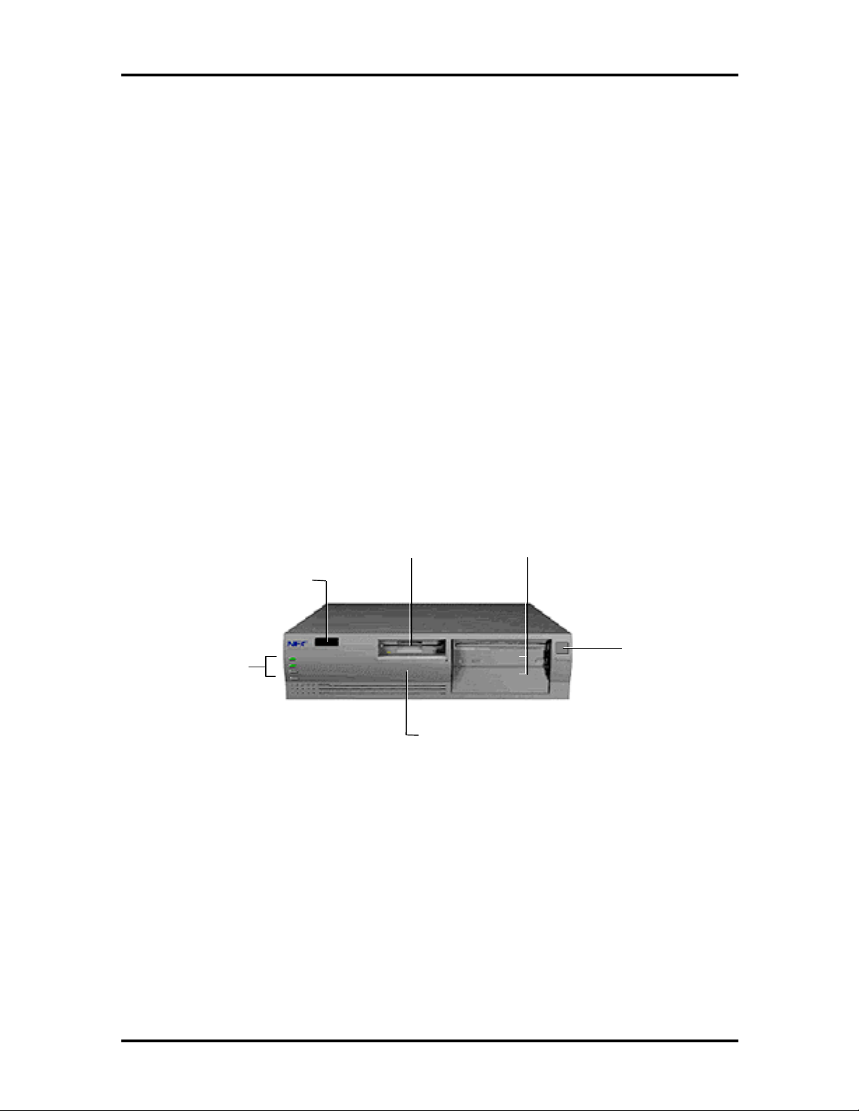
Figure 1-1 shows front panel features and locations of the accessible storage devices in a
desktop system. Multimedia systems come with a CD-ROM reader installed in the top
accessible device slot.
3 1/2-Inch
Diskette Drive
IR Window
System Controls
and Lamps
3 1/2-Inch Internal
Hard Drive Slot
(behind panel)
5 1/4-Inch Accessible
Dev ice Slot s
Figure 1-1 Desktop System Controls and Storage Device Slots
Power Button
1-4 Technical Information
MINITOWER SYSTEM CHASSIS
The minitower chassis provides an enclosure for the system board, power supply, five
useable expansion slots, a six-connector PCI/ISA backboard, and seven storage device
slots. The expansion slots include three 8-/16-bit ISA slots, one shared PCI/ISA slot, and
one 32-bit PCI slot. For network-ready configurations, one slot has a network board
installed and the remaining slots are open.
The seven storage device slots accommodate up to four accessible devices and three
internal hard disk drive devices. The accessible devices include the standard one-inch high
3 1/2-inch 1.44-MB diskette drive and up to three 1.6-inch high 5 1/4-inch storage devices.
The internal device slots support up to three 3 1/2-inch hard disks; one in the standard front
slot. The other two install into a drive bracket that ships with the system. The bracket
attaches to the inside rear of the system.
The non-multimedia hard disk systems ship with an accessible 3 1/2-inch diskette drive and
an internal 3 1/2-inch hard disk drive, leaving three accessible 5 1/4-inch storage device
slots and two internal slots available for optional devices. The multimedia systems ship with
an accessible 3 1/2-inch diskette drive, an internal 3 1/2-inch hard disk drive, and an
accessible 5 1/4-inch CD-ROM reader, leaving two accessible 5 1/4-inch storage device
slots and two internal slots available for optional devices.
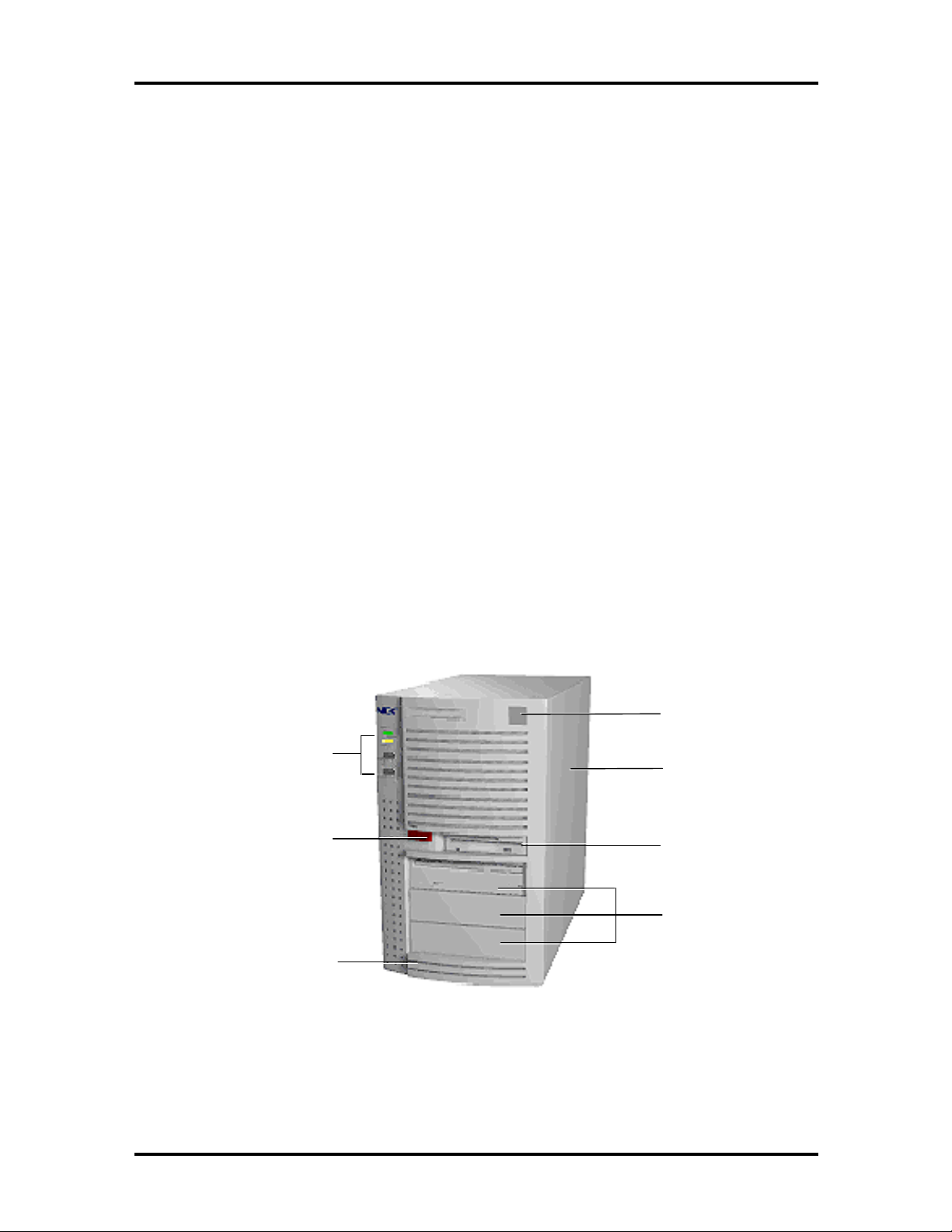
Figure 1-2 shows the front panel features and the locations of the accessible storage devices
in a minitower system. Multimedia systems come with a CD-ROM reader installed in the
top accessible device slot.
Power Button
System Controls
and Lamps
IR Window
3 1/2-Inch Internal
Hard Drive
(behind cover)
Figure 1-2 Minitower System Controls and Storage Device Slots
3 1/2-Inch Internal
Hard Disk Slots
(behind cover)
3 1/2-Inch
Diskette Drive
5 1/4-Inch
Accessible Device
Slots

SYSTEM BOARD
Key features of the system board include the following:
Intel Pentium 75-, 90-, 100-, or 133-MHz Pentium processor, depending on
system configuration
16-KB internal dual write-back cache integrated on the processor
256-KB write-back secondary static random access memory (SRAM)
PowerMate V75 (first release) – 20-nanosecond (ns), asynchronous, SRAM,
cache module
PowerMate V90 and V100 (first release) – 15-ns, asynchronous, SRAM,
cache module
PowerMate V75, V100, and V133 (second release) – 15-ns, synchronous
pipeline burst, SRAM, cache module
system Setup program built into the BIOS
Technical Information 1-5
flash ROM for fast economical BIOS upgrades
integrated input/output (I/O) controller with keyboard, diskette drive, and hard
disk drive controllers. Supports two serial ports, a parallel port, and an IrDA port.
PCI local bus for fast data transfer
support for Intel OverDrive™ processors
8-MB RAM (16 MB in multimedia configurations, 1.2 GB, and 1.6 GB hard disk
configurations)
ships with 32-bit, non-parity, 70-ns single-inline memory modules (SIMMs)
RAM expandable up to 128 MB
integrated graphics
Peripheral Component Interconnect (PCI) graphical user interface (GUI)
accelerator and motion video playback controller using Alliance
ProMotion-6422™
standard 1-MB (two 256K x 16) video DRAM, expandable to 2 MB
standard 1-MB video DRAM supports resolutions of 640 x 480 with up to
16.8 million colors, 800 x 600 with up to 64K colors, 1024 x 768 with up to
256 K colors, and 1280 x 1024 with up to 16 colors

1-6 Technical Information
integrated sound (multimedia configurations only)
OPTi Sound Blaster compatible chip on system board
Yamaha OPL3 FM synthesis chip on system board
built-in 16-bit stereo and FM synthesis
Wavetable sound upgradeable
3D sound effects
two intelligent drive electronics (IDE) interface channels
one fast IDE/PCI channel (primary connector) used by the hard disk drive to
transfer data at the hard disk’s optimum rate
one standard IDE channel (secondary connector) for the CD-ROM reader
supports up to four IDE devices, two to each channel
power management for placing system in power save mode when idle for a
specified amount of time
3 1/2-inch, 1.44-MB diskette drive standard all configurations
PCI/ISA backboard configurations
desktop provides four expansion slots: two ISA, one PCI, and one shared
ISA/PCI connectors
minitower provides five expansion slots: three ISA, one PCI, and one shared
ISA/PCI connectors
external connectors for connecting the following external devices:
VGA-compatible monitor (standard, super, high-resolution VGA)
personal system/2 (PS/2®)-style mouse
PS/2-style keyboard
bidirectional Enhanced Parallel Port (EPP) and enhanced capabilities port
(ECP) are supported for a parallel printer
serial devices through two buffered 16C550 UART serial ports, each
supporting up to 19.2 KB per second
external speakers, microphone, and headphone connectors (multimedia
configurations only)
Technical Information 1-7
y
y
MIDI/joystick connector on the system board for installation of an optional
MIDI/joystick kit
Audio Wave upgrade connector on the system board for installation of an optional
Wave upgrade.
Table 1-3 lists the major chips on the system board. See Appendix A, Connector Pin
Assignments, for a list of the system board connectors. See Appendix B, System Board
Jumpers, for a description of board jumpers.
Table 1-3 System Board Chips
Chip Description
P54C (CPGA) 75/50-MHz Intel Pentium processor
90/60-MHz Intel Pentium processor
100/66-MHz Intel Pentium processor
133/66-MHz Intel Pentium processor
Intel Triton 82430FX PCI/ISA Chip Set
82437FX
82438FX
824371FB
SMC FDC37C935 or 665 Integrated Plug and Play Ultra I/O controller
Alliance ProMotion-6422 PCI GUI graphics controller
28F001 128k x 8 Flash ROM
Dallas DS12887/MC146818
or
Toshiba CR2032 Coin Cell Battery
OPTi 82C930 Sound Chip
(multimedia systems only)
Yamaha OPL3-L Synthesizer Chip
(multimedia systems only)
stem controller
S
Data path unit
PCI ISA/IDE accelerator bridge chip
Real-time clock/batter
or
3 Volt Lithium CMOS battery (SMC 935)
Onboard PC sound system
Frequency modulated synthesizer
(SMC 665)
Processor
The PowerMate V series of computers use the following Pentium processors:
PowerMate V75 — 75-MHz processor with internal speed of 75 MHz and
external speed of 50 MHz.
PowerMate V90 — 90-MHz processor with internal speed of 90 MHz and
external speed of 60 MHz

1-8 Technical Information
PowerMate V100 — 100-MHz processor with internal speed of 100 MHz and
external speed of 66 MHz.
PowerMate V133 — 133-MHz processor with internal speed of 133 MHz and
external speed of 66 MHz.
Each processor has 16 KB of write-back primary cache and a math coprocessor. The 16 KB
primary cache provides 8 KB for instructions and 8 KB for data.
The processor is an advanced pipelined 32-bit addressing, 64-bit data processor designed to
optimize multitasking operating systems. The 64-bit registers and data paths support 64-bit
addresses and data types.
To use the Pentium processor’s power, the system features an optimized 64-bit memory
interface and complementary asynchronous pipelined 256-KB secondary cache.
The processor is compatible with 8-, 16-, and 32-bit software written for the Intel386™,
Intel486™, and Pentium processors.
To accommodate future technologies and work requirements, the Pentium processor comes
in a 320-pin zero insertion force (ZIF) socket. The socket provides an upgrade path to the
next generation processor.
Secondary Cache
The system board contains 256 KB of secondary cache, external to the processor. The first
release shipped uses 15-ns asynchronous SRAM (PowerMate V90 and V100) or 20-ns
asynchronous SRAM (PowerMate V75) cache. The second release of the PowerMate V
series ships with 15-ns synchronous pipe line burst cache.
Cache allows data to be sent or received from cache with one wait state burst. Cache
memory improves read performance by holding copies of code and data that are frequently
requested from the system memory by the processor. Cache memory is not considered part
of the expansion memory.
System and Video BIOS
The system and video BIOS are stored in a 1 MB (128 KB by 8) flash memory device
(Flash ROM). The system BIOS uses 64 KB, the video BIOS uses 32 KB, and 32 KB is
reserved. The system BIOS is capable of being shadowed and cached through the system’s
Setup utility (see Section 2 for Setup information). System BIOS is write protected and
automatically enabled.
The BIOS programs execute the Power-On Self-Test, initialize processor controllers, and
interact with the display, diskette drives, hard disks, communication devices, and
peripherals. The system BIOS also contains the Setup utility. The hardware setup default
copies the ROM BIOS into RAM (shadowing) for maximum performance.

Technical Information 1-9
The Flash ROM allows the system and video BIOS to be upgraded with the BIOS Update
utility, without removing the ROM (see Section 2 for further information on the BIOS
Update utility). The Flash ROM supports the reprogramming of the system BIOS and the
video BIOS.
The system memory map is provided in Table 1-4.
Table 1-4 System Memory Map
Memory Space Size Function
00000000-0009FFFF 640 KB Conventional base memory
000A0000-000BFFFF 128 KB Video buffer
000C0000-000C7FFF 32 KB Video BIOS
000C8000-000EFFFF 160 KB Expansion
000F0000-000FFFFF 64 KB System BIOS
00100000-00EFFFFF 14 MB Cacheable
00F00000-00FFFFFF 1 MB Optional memory space
01000000-03FFFFFF 48 MB Always cacheable
04000000-07FFFFFF 64 MB L1 cache only
FFF80000-FFFFFFFF 512 KB BIOS ROM
System Memory
Non-multimedia systems come standard with 8 MB of memory: 640 KB of base memory
and 7 MB of extended memory. All multimedia, 1.2 GB, and 1.6 GB hard disk
configurations come standard with 16 MB of memory: 640 KB of base memory and 15 MB
of extended memory. System memory can be expanded up to 128 MB, using optional single
in-line memory modules (SIMMs) installed in SIMM sockets on the system board.
Four SIMM sockets are integrated on the system board. Non-multimedia systems ship with
two 4-MB SIMMs (8 MB total) installed in two sockets. The multimedia, 1.2 GB, and 1.6
GB hard disk configurations ship with two 8-MB SIMMs (16 MB total) installed in two
sockets.
The SIMM memory sockets accept 32-bit (non-parity) 4-, 8-, 16-, or 32-MB 70 ns SIMMs.
The SIMMs are 1 MB x 32 bit (4 MB), 2 MB x 32 bit (8 MB), 4 MB x 32 bit (16 MB), and
8 MB x 32 bit (32 MB). When the standard SIMMs are removed, four 32-MB SIMMs may
be installed for a total of 128 MB.
CAUTION:
SIMMs must match the tin metal
plating used on the system board SIMM sockets.
When adding SIMMs, use tin-plated SIMMs.

1-10 Technical Information
SIMMs install directly in the four sockets on the system board. The four sockets are
assigned as SIMM 1 through SIMM 4. For non-multimedia configurations, the two
standard 4 MB SIMMs are installed in SIMM 1 and SIMM 2. For multimedia
configurations, the two standard 8 MB SIMMs are installed in SIMM 1 and SIMM 2.
SIMMs must be installed in pairs of the same memory type. Jumpers are not required to set
memory size or type as the system BIOS automatically detects the SIMMs. SIMM banks 1
and 2 must always be filled for the system to operate. Table 1-5 shows the SIMM memory
upgrade path.
Table 1-5 SIMM Memory Upgrade Path
Total Memory SIMM 1 SIMM 2 SIMM 3 SIMM 4
8 MB 4 MB 4 MB Empty Empty
16 MB 4 MB 4 MB 4 MB 4 MB
16 MB 8 MB 8 MB Empty Empty
24 MB 4 MB 4 MB 8 MB 8 MB
24 MB 8 MB 8 MB 4 MB 4 MB
32 MB 8 MB 8 MB 8 MB 8 MB
32 MB 16 MB 16 MB Empty Empty
40 MB 4 MB 4 MB 16 MB 16 MB
40 MB 16 MB 16 MB 4 MB 4 MB
48 MB 8 MB 8 MB 16 MB 16 MB
48 MB 16 MB 16 MB 8 MB 8 MB
64 MB 16 MB 16 MB 16 MB 16 MB
64 MB 32 MB 32 MB Empty Empty
72 MB 4 MB 4 MB 32 MB 32 MB
72 MB 32 MB 32 MB 4 MB 4 MB
80 MB 8 MB 8 MB 32 MB 32 MB
80 MB 32 MB 32 MB 8 MB 8 MB
96 MB 16 MB 16 MB 32 MB 32 MB
96 MB 32 MB 32 MB 16 MB 16 MB
128 MB 32 MB 32 MB 32 MB 32 MB

Technical Information 1-11
Integrated Graphics
The system has an Alliance ProMotion-6422 PCI local bus motion video playback
controller and graphics accelerator integrated on the system board. State of the art
techniques are used for optimizing performance in computer graphic intensive applications
and graphical user interfaces (GUI).
The integrated graphics controller integrates a motion video controller, a high-performance
GUI accelerator, 24-bit high frequency DAC and clock generator, VESA®-compliant
feature connector, and 1 MB of fast 64-bit DRAM (upgradeable to 2 MB).
Motion Video Controller
The motion video controller integrates a powerful Windows® GUI engine and unique
motion video playback hardware for superior performance. The graphics engine includes an
on-chip color space converter to accelerate decompression and a hardware scaler to scale
continuously from native size up to full screen at full speed. The graphics engine delivers a
full screen, smooth display of motion video data up to 30 frames per second (fps). Support
includes MPEG-1 and Video for Windows.
MPEG is a compression/decompression standard developed by the Motion Picture Experts
Group. MPEG produces full-screen 30 fps, broadcast-quality digital video. The video
controller architecture maximizes the motion video performance and removes bandwidth
bottlenecks to display multimedia data at its full speed.
Graphics Accelerator
The graphics accelerator is specifically designed for graphics-intensive operations, text and
color pixel amplification, and scrolling. The graphics accelerator provides 64-bit, ultra-high
performance for demanding True Color, High Color, and pseudocolor GUI and CAD
applications.
The accelerator minimizes bus traffic by off-loading the tasks normally performed by the
processor. The dedicated bit-block transfers (BitBLT) engine maximizes performance by
speeding the movement of large blocks of image data in video memory.
Video Memory
The system comes with 1 MB of on-board video DRAM, upgradeable to 2 MB. The
standard 1 MB DRAM consists of two 256K by 16 DRAM devices soldered to the system
board. The optional 1 MB of DRAM consists of two 256 KB by 16 modules that install in
two sockets on the system board.

1-12 Technical Information
With the standard 1 MB of video DRAM, the video hardware supports the following
resolutions, colors, and refresh rates:
1280 by 1024 pixels, 16 colors, 60 Hz
1024 by 768 pixels, 16/256 colors, 60 Hz, 66 Hz, 70 Hz, 72 Hz, and 75 Hz
800 by 600 pixels, 16/256/64K colors, 56 Hz, 60 Hz, 72 Hz, and 75 Hz
640 by 480 pixels, 16/256/64K/16.8 million colors, 60 Hz, 72 Hz, and 75 Hz.
With 2 MB of video DRAM, the system supports the following additional resolutions,
colors, and refresh rates:
1600 by 1200 pixels, 16/256 colors, 60 Hz and 70 Hz
1280 by 1024 pixels, 256 colors, 60 Hz, 72 Hz, and 75 Hz
1024 by 768 pixels, 64K colors, 60 Hz, 66 Hz, 70 Hz, 72 Hz, and 75 Hz
800 by 600 pixels, 16.8 million colors, 56 Hz, 60 Hz, 72 Hz, and 75 Hz.
Interrupt Controller
The interrupt controller operates as an interrupt manager for the entire AT system
environment. The controller accepts requests from peripherals, issues interrupt requests to
the processor, resolves interrupt priorities, and provides vectors for the processor to
determine which interrupt routine to execute. The interrupt controller has priority
assignment modes that can be reconfigured at any time during system operations.

Technical Information 1-13
The interrupt levels are described in Table 1-6. Interrupt-level assignments 0 through 15 are
in order of decreasing priority. See Section 2, Setup and Operation, for information on
changing the interrupts using Setup.
Table 1-6 Interrupt Assignments
Interrupt
Priority
IRQ00 Counter/Timer
IRQ01 Keyboard
IRQ02 Cascade (INT output from slave)
IRQ03 COM2 and COM4
IRQ04 COM1 and COM3
IRQ05 Parallel Port 2/Audio (if present)
IRQ06 Diskette Drive Controller
IRQ07 Parallel Port 1
IRQ08 Real-time clock
IRQ09* Available
IRQ10* Available
IRQ11* Available
IRQ12 PS/2 mouse
IRQ13 Coprocessor
Interrupt Device
IRQ14 Primary IDE
IRQ15 Secondary IDE
* Network and multimedia configurations use one of the these
interrupts.

1-14 Technical Information
I/O Addressing
The processor communicates with I/O devices by I/O mapping. The hexadecimal (hex)
addresses of I/O devices are listed in Table 1-7.
Table 1-7 I/O Address Map
Address (Hex) I/O Device Name
0000-000F DMA controller 1 (channel 0-3)
0020-0021 Interrupt controller 1
0040-0043 Timer 1
0048-004B Timer 2
0061 NMI status and control
0064 Keyboard controller byte
0070-007F Real-time clock, NMI mask
0080-008F DMA page registers
00A0-00A1 Interrupt controller 2
00C-00DE DMA controller 2
00E0-00EF Reserved
00F0 Clear math coprocessor error
00F1 Reset math coprocessor
0F8-0FF Math coprocessor
170-177 Secondary hard disk controller
1F0-1F7 Primary hard disk controller
200-207 Game I/O
220-22F Sound port
238-23F Serial port 4 (used for remapping)
278-27F Parallel port 2
2B0-2DF Alternate EGA adapter
2F8-2FF Serial port 2
338-33F Serial port 3 (used for remapping)
378-37F Parallel port 1
3B0-3BF Mono display and printer adapter
3C0-3CF EGA adapter
3D0-3DF CGA adapter
3F0-3F7 Primary diskette drive controller
3F8-3FF Serial port 1
CF8-CFF PCI configuration
 Loading...