

NEC PowerMate SPB-Wash, Direction SP B User Manual

Proprietary Notice and Liability Disclaimer
The information disclosed in this document, including all designs and
related materials, is the valuable property of NEC Computer Systems
Division, Packard Bell NEC, Inc. (hereinafter “NEC CSD”) and/or its
lice nsor s. N EC CSD a nd/or it s lic ens ors, as app ropr iat e, reser ve all pat ent,
copyright and other proprietary rights to this document, including all
desi g n, manufa ct u r ing, r ep r odu ct i o n, us e, a nd sa l es r ight s t h er et o, exc e pt to
the ex tent said right s are expr es sly granted to other s.
The NEC CSD product(s) discussed in this document are warranted in
accordanc e with the t erms of the War ranty Statement accompa nying each
product. However, actual performance of each such product is dependent
upon factors such as system configuration, customer data, and operator
contr ol. Since i mple menta ti on by cu stomer s of each p rodu ct ma y var y, th e
suitability of specific product configurations and applications must be
determined by the customer and is not warranted by NEC CSD.
To allow for design and specification improvements, the information in this
document is subject to change at any time, without notice. Reproduction of
this document or portions thereof without prior written approval of
NEC C SD is prohibited.
FaxFlash is a service mark of NEC CSD, Packard Bell NEC, Inc.
Dir ection and Vist aS can are trademarks of Packard Be l l NEC, Inc.
NEC and MultiSync ar e registere d tr ademarks of NE C C orporation, used und er licen se.
All other product, brand, or trade names used in this publication are the trademarks or
register ed trademarks of their respective trademark owners.
First Printing — October 1998
Copyright 1998
NEC Computer Systems Division
Packar d Bell NEC, Inc.
1 Packar d Bell Way
Sacramento, CA 95828-0903
All Rights Reserved

Contents
Using This Guide
Text Conventions..............................................................................x
Related Documents..........................................................................xi
1 Reviewing System Features
Front Features ............................................................................... 1-3
System Controls and Lamps .................................................. 1-4
Diskette Drive A.................................................................... 1-5
CD-ROM/DVD Drive........................................................... 1-6
Back Features ............................................................................... 1-8
External Connectors .............................................................1-11
Power Supply...............................................................................1-13
Zip Drive.....................................................................................1-13
Speakers......................................................................................1-14
Mouse..........................................................................................1-15
Microphone .................................................................................1-15
2 Using Your Computer
System Operation..........................................................................2-2
Starting Up ............................................................................ 2-2
Shutting Down ...................................................................... 2-3
Setting the Date and Time...................................................... 2-5
Using Diskettes..................................................................... 2-5
Using CDs............................................................................. 2-6
Handling Compact Discs................................................ 2-6
Loading a CD................................................................ 2-8
Removing a CD............................................................. 2-8
Using Your System’s Audio Functions.................................. 2-8
Setting Power Management................................................... 2-9
Protecting Your System ......................................................... 2-9
Setting a Password ........................................................2-10
Using a Password..........................................................2-11
Productivity.................................................................................2-11
Saving Your Work................................................................2-12
Contents iii

Backing Up Your Work........................................................2-12
Printing a Document.............................................................2-13
Display Properties........................................................................2-14
System Care.................................................................................2-15
Protecting Your System From Damage .................................2-15
Keeping Your System in Good Condition.............................2-16
Moving or Shipping Your System.........................................2-17
Online Documentation.................................................................2-18
Where to Go From Here...............................................................2-18
3 Understanding System Features
Standard Features.......................................................................... 3-2
System Chassis............................................................................. 3-3
System Board Components........................................................... 3-3
Processor............................................................................... 3-3
Drive Interfaces..................................................................... 3-3
Ports...................................................................................... 3-3
System Memory.................................................................... 3-4
Intel Xcelerator Multifunction Controller............................... 3-4
Flash ROM............................................................................ 3-4
Plug and Play ........................................................................ 3-5
Graphics and Multimedia Features......................................... 3-5
Accelerated Graphics Port (AGP) Interface.................... 3-5
Video Support................................................................ 3-5
Audio............................................................................. 3-6
Super I/O Controller.............................................................. 3-6
USB Ports............................................................................. 3-7
Dual IDE Channels................................................................ 3-7
Power-Saving Feature............................................................ 3-7
Options and Upgrades................................................................... 3-8
Network Interface Card......................................................... 3-8
Modem.................................................................................. 3-8
Removable Storage................................................................3-8
Keyboard............................................................................... 3-8
Speakers................................................................................ 3-8
Audio.................................................................................... 3-9
Video.................................................................................... 3-9
iv Contents

4 Configuring the System
System BIOS and the Setup Utility................................................ 4-2
Setup Utility.......................................................................... 4-2
When to Use Setup........................................................ 4-3
How to Start Setup......................................................... 4-4
How to Use Setup.......................................................... 4-4
Maintenance Menu ................................................................ 4-5
Main Menu............................................................................ 4-6
Advanced Menu.................................................................... 4-8
Peripheral Configuration Submenu................................. 4-9
IDE Configuration Submenu.........................................4-10
Floppy Options Submenu..............................................4-13
DMI Event Logging Submenu.......................................4-14
Video Configuration Submenu......................................4-15
Resource Configuration Submenu.................................4-15
Security Menu......................................................................4-17
How to Set a Password..................................................4-18
How to Disable Password Protection.............................4-19
Power Menu.........................................................................4-21
Boot Menu...........................................................................4-22
Hard Drive Submenu ....................................................4-24
Removable Devices Submenu.......................................4-25
Removable Format Submenu ........................................4-25
Exit Menu............................................................................4-25
BIOS Flash Utility.......................................................................4-27
Video Drivers ..............................................................................4-28
Jumper Settings............................................................................4-29
Locating the Jumper.............................................................4-29
Clearing Your Password.......................................................4-30
Recovering the BIOS............................................................4-32
5 Installing Options
Option Installation ........................................................................ 5-2
Safety Precautions................................................................. 5-2
Cover Removal and Replacement.................................................. 5-4
Removing the Access Cover.................................................. 5-4
Replacing the Access Cover .................................................. 5-6
Expansion Boards......................................................................... 5-7
Contents v

Installing an Expansion Board............................................... 5-9
Removing an Expansion Board.............................................5-12
Memory Upgrade.........................................................................5-13
Removing a DIMM..............................................................5-15
Installing a DIMM................................................................5-16
Data Storage Devices...................................................................5-18
Locating Device Slots...........................................................5-18
Preparing the Device............................................................5-19
Identifying Device Cables.....................................................5-20
Diskette Drive Signal Cable..........................................5-20
IDE Signal Cables.........................................................5-21
System Power Cables....................................................5-22
Cabling Storage Devices.......................................................5-23
Cabling an IDE Device.................................................5-23
Cabling an Accessible 5 1/4-Inch Device......................5-25
Installing Storage Devices....................................................5-25
Removing the Front Panel.............................................5-26
Removing the CD-ROM/DVD Drive............................5-27
Installing a 3 1/2-Inch Device........................................5-28
Installing a 5 1/4-Inch Device........................................5-33
Replacing the Front Panel .............................................5-35
External Options..........................................................................5-35
Connecting a Parallel Printer................................................5-36
Connecting a Serial Device...................................................5-37
6 Solving System Problems
Problem Checklist......................................................................... 6-3
Solutions to Common Problems.................................................... 6-4
System Problems ................................................................... 6-4
Diskette Drive Problems........................................................ 6-6
Monitor Problems.................................................................. 6-6
Keyboard/Mouse Problems.................................................... 6-7
CD-ROM/DVD Drive Problems............................................ 6-8
Speaker Problems.................................................................. 6-8
Microphone Problems............................................................ 6-9
Getting Help................................................................................. 6-9
Getting Help From Your Company........................................ 6-9
Getting Help From Your NEC CSD Dealer...........................6-10
vi C ont ents

Getting Help From NEC CSD Technical Support .................6-10
NEC CSD Warranty/Non-Warranty Repair Service ..............6-10
Battery Replacement....................................................................6-11
7 Getting Services and Support
NEC CSD Website........................................................................ 7-2
NEC CSD FTP Site....................................................................... 7-3
NEC CSD FaxFlash Service.......................................................... 7-4
NEC CSD Bulletin Board Service................................................. 7-6
Email/Fax Technical Support Service............................................ 7-8
NEC CSD Technical Support Services.......................................... 7-9
A Setting Up a Healthy Work Environment
Making Your Computer Work for You..........................................A-2
Arrange Your Equipment.............................................................. A-4
Adjust Your Chair.........................................................................A-5
Adjust Your Input Devices ............................................................A-7
Adjust Your Monitor.....................................................................A-9
Vary Your Workday....................................................................A-11
Preexisting Conditions and Psychosocial Factors.........................A-12
Checking Your Comfort: How Do You Measure Up?..................A-13
Checking Your Chair...........................................................A-13
Checking Your Keyboard....................................................A-13
Checking Your Mouse.........................................................A-13
Checking Your Monitor....................................................... A-13
Checking You ..................................................................... A-14
B System Specifications
Standard Features..........................................................................B-2
Processor...............................................................................B-2
Second Level Cache..............................................................B-2
Memory ................................................................................B-3
Chipset..................................................................................B-5
Intel 82440BX PCI/AGP Controller (PAC)....................B-5
Intel 82371EB PCI ISA IDE Xcelerator (PIIX4E)..........B-7
Accelerated Graphics Port (AGP)...................................B-8
Universal Serial Bus (USB) Support...................................... B-9
Content s vii

IDE Support.......................................................................... B-9
Super I/O Controller............................................................B-10
Serial Ports..........................................................................B-10
Parallel Port.........................................................................B-10
Diskette Drive Controller.....................................................B-10
Keyboard and Mouse...........................................................B-11
Interrupt Requests (I R Q s )....................................................B-11
Audio Support.....................................................................B-12
Audio Subsystem.........................................................B-12
Audio Connectors........................................................B-12
CD-ROM Audio Connector .........................................B-12
Expansion Slots...................................................................B-13
BIOS...................................................................................B-13
Monitor Support..................................................................B-13
Power Supply......................................................................B-14
Power Consumption.....................................................B-15
DC Voltage..................................................................B-15
Environmental Specifications......................................................B-15
Ambient Temperature.......................................................... B-15
Humidity .............................................................................B-16
C System Board, Connectors, and Error Messages
System Board................................................................................C-2
Connectors....................................................................................C-3
Rear Panel Connectors...........................................................C-3
Internal Connectors ...............................................................C-4
Error Messages.............................................................................C-8
Beep Codes.................................................................................C-11
Glossary
Index
viii Contents

Using This Guide
The NEC Direction SP B-Series User’s Guide provides a
quick reference to information about your computer.
This guide contains the following information:
Chapter 1, Reviewing System Featur es, provides a loo k at
system components. See this chapter to familiarize
yourself with your system.
Chapter 2, Using Your Computer, explains how to start up
and shut down your system, use your s ystem components,
and care for your system.
Chapter 3, Understanding System Features, provides a
quick overview of the various features of your system.
Chapter 4, Configuring the System, describes the system
BIOS Setup utility progr am and other utilities you can use
to configure your system. This chapter provides detailed
information about BIOS settings, including security and
power management parameters. Jumper setting
info rmation is also co ntained in t his cha pte r.
Chapter 5, Inst alling Opt ions, p rovides inst allation
instructions and in some cases, r emoval proced u r es for the
options.
Chap ter 6, Solving System Pr oble ms , contains
troubleshooting tip s for solving si mple problems an d
provides information on where you can find help when
you cannot solve a problem yourself.
Chapter 7, Getting Services and Support, lists the services
available to you for information and help, and describes
how to access the service s.
Using This Guide ix

Appendix A, Setting Up a Healthy Work Environment,
contains guidelines to help you use your computer
productively and safely. This appendix also instructs you
on how to set up and use your computer to reduce your
risk of developing nerve, muscle, or tendon disorders.
!
WARNING
Prolonged or improper use of a c om puter
workstation may pose a risk of serious injury. To
reduce your risk of i njur y, set up and use your
computer in the manner described in Appendix
A, Setting Up a Healthy Work Envir onm ent.
Appendix B, System Specifications, provides a technica l
description of your computer and its components.
Appendix C, System Board, Connectors, and Error
Messages, pro vides a t echnical descr iption of the system
board and co nnectors. This append ix also describes system
error messages.
Text Conventions
This guide uses the following text conventions.
Warnings, caut ions, and notes have the following
meanings:
!
WARNING
Warnings alert you to situations that could result
in serious personal injury or loss of life.
x Using This Guide

!
CAUTION
Cautions indi c ate situations that can damage the
hardware or software.
Notes give important inf ormation about
Note:
the material bei ng described.
Names of keyboard keys are printed as they appear on the
Enter
Ctrl, Alt
.
keyboard, for example,
Text or keystrokes that you enter appear in boldface type.
For example, press
Filenames are printed in uppercase letters.
Related Documents
In addition to this guide, the following printed documentation
ships with your NEC Direct ion SP B-Series system:
NEC Direction SP B-Series Quick Setup
Quick Setup contains information for quickly getting your
system up and running. See this information to set up the
system for the first time.
, or
Enter
.
How Does Your Workplace Measure Up?
This brochure provides information for setting up and
using your computer productively and safely. Informat ion
includes guidelines to reduce the risk of injury associated
with using a computer.
Using This Guide xi

Your system ships with additional documentation depending
on your configuration and any options you selected. S ee the
documentation specific to devices such as your monitor,
speakers, and video graphics board for detailed information
about the m.
In addition to the documentation that ships wit h t he syst em,
the following documentat ion is available fro m NEC CSD:
NEC Direction SP B-Series Service and Reference Manual
This manu al pro vid e s in formatio n for mainta in ing ,
troubleshooting, and repairing NEC Direction
SP B-Series systems. This manual also includes hardware
and interface infor mat ion for pro g r ammers, engineers, and
others who need to know how the systems are designed.
The manual ca n be found on t he NEC C SD we bsite. Se e
“NEC CSD Website” in Chapter 7.
NEC CSD FaxFlash
SM
Service
NEC CSD FaxFlash is an automated service that sends the
latest information about NEC CSD and its products
directly to a fax machine. The service is available 24 hours
a day, 7 days a week.
With FaxFlash, you can obtain product literature and
technical information bulletins. By using FaxFlash, you
can be kept up-to-date on the latest technical information
for your system.
See Chapter 7 for informat ion about using FaxFlash.
xii Using This Guide

Reviewing System
Features
Front Features
Back Features
Power Supply
Zip Drive
Speakers
Mouse
Microphone
1

!
WARNING
Prolonged or improper use of a c om puter
workstation may pose a risk of serious injury. To
reduce your risk of i njur y, set up and use your
computer in the manner described in Appendix
A, Setting Up a Healthy Work Envir onm ent.
Your NEC Direction™ SP B-Series multimedia
computer comes with state-of-the-art, high-performance
components for deliver ing years o f service. Based on an
Intel® Pentium® II pro cessor with MMX™ tech nology,
your system has the power and speed to tackle all today’s
computing needs and most of tomorrow’s.
After setting up your system, take the time to familiarize
yourself with your computer. This chapter provides a brie f
look at the features of your syste m.
Note:
This guide cover s both deskt op and
minitower models of the NEC Direction SP
B-Series system. Features are identical for
desktop and minitower systems; only their
orientation differs.
1-2 Reviewing System Features

Front Features
Daily contact with your syste m is through the controls on the
front panel. The following figures show the cont rol features
on the fr ont of the system.
Front features — desktop models
A – Power Lamp B – Power Button
C – Disk Lamp D – Reset Button
E – Diskette Drive F – CD-ROM/DVD Drive
Reviewing System Features 1-3
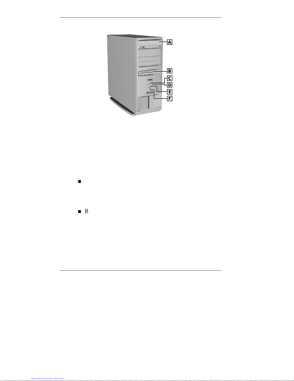
Front panel features — minitower models
A – CD-ROM/DVD Drive B – Diskette Drive
C – Power Lamp D – Power Button
E – Disk Lamp F – Reset Button
System Controls and Lamps
System contro ls let you se lect specific system operations; the
lamps let you know the s tat us of sys te m oper atio n. Your
computer has the fo llowing contr ols and lamps:
Power button
Turns the system on and off. The lig ht is green when the
system is on and is amber when the system is in Standby
or Suspend mode.
Reset button
Lets you restart your system manually when it does not
respond to keyboard commands.
1-4 Reviewing System Features

Resetting your system can result in the loss of
data. Press the reset butt on only when all other
methods of restarting your computer fail.
Power lamp
Lights when the system is turned on.
Disk la mp
Lights when the hard drive is active, reading or writing
data.
Do not turn off the system, unless absolutely
necessary, while the disk lamp is lit. To do so
can damage your hard drive or data.
Diskette Drive A
Your diskette drive has the following features:
!
CAUTION
!
CAUTION
Diskette drive bu sy lamp
Lights when the diskette drive is active, reading or writing
data on a diskette.
!
CAUTION
To prevent damage to your disket te drive and
data, do not turn off the system or remove a
diskette whil e the diskette drive busy lamp is lit.
Diskette drive eject button
Lets you remove a diskette from the diskette drive.
Reviewing System Features 1-5
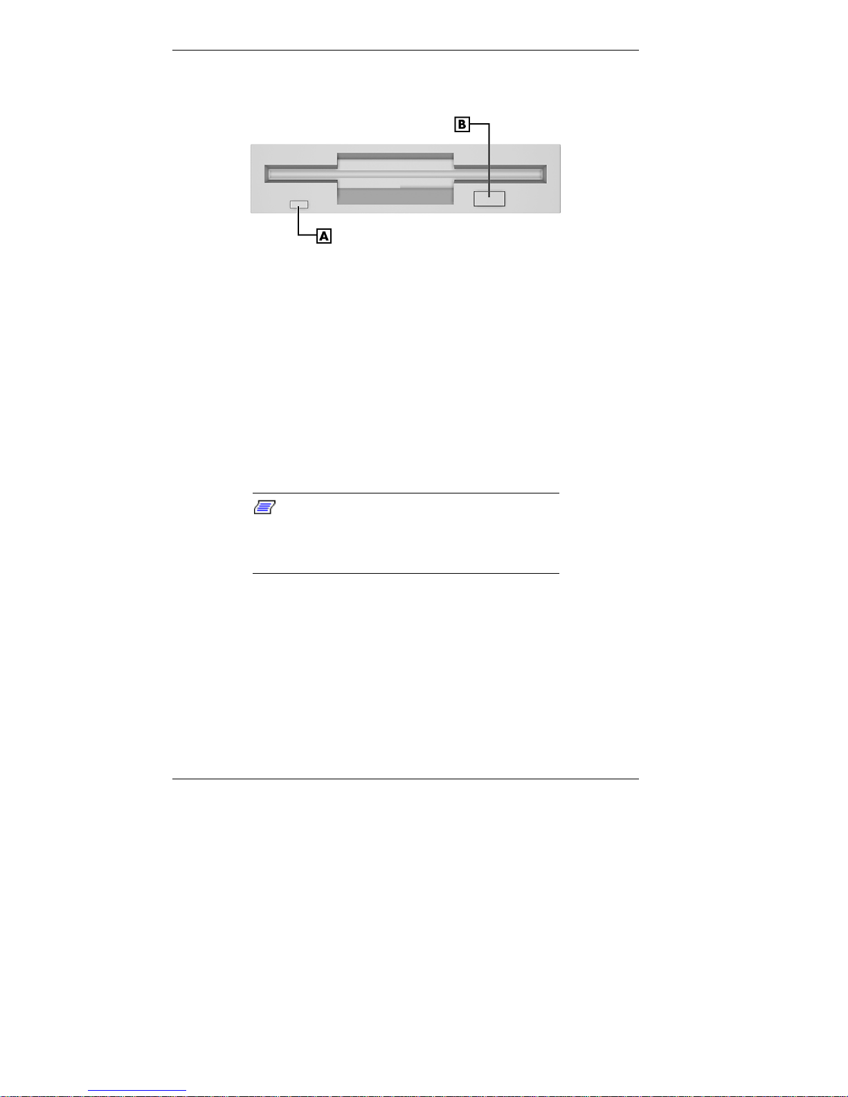
Diskette drive features
A – Diskette Drive Busy Lamp B – Dis kette Drive Eject But ton
CD-ROM/DVD Drive
Your computer comes with a high-speed ATAPI CD-ROM
drive or a DVD drive. The CD-ROM/DVD drive operat es at
different speeds depending on whether the CD you are using
contains data or music. High-speed op er ation lets you get
your data faster and see smoother animation and video.
The CD-ROM/DVD drive in your
Note:
system might look different from the one shown
in the following figure. The features depend upon
the model you purchased.
1-6 Reviewing System Features
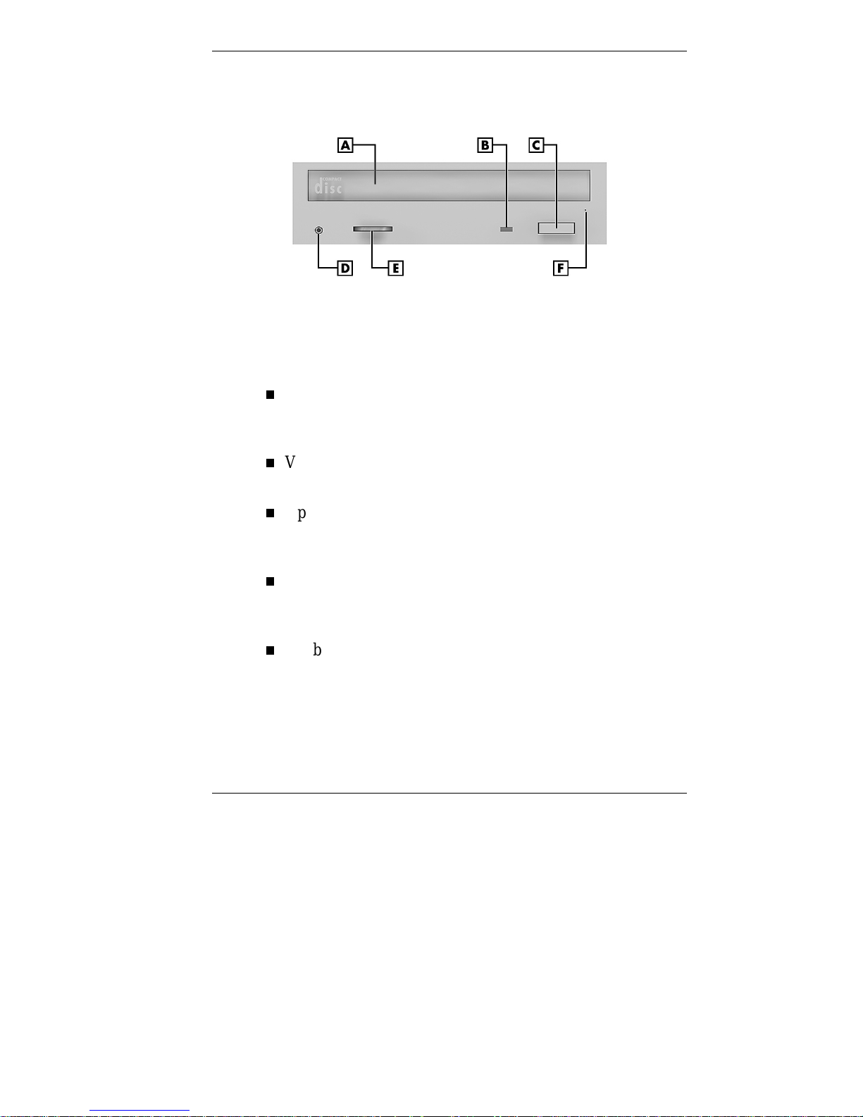
CD-ROM/DVD drive feat ures
A – CD Tray B – CD Busy Lamp
C – Open/Close Button D – Headphone Jack
E – Volume Control Knob F – Emergency Eject Hole
Headphone jack
Allows the connect ion of an opt ional set of stereo
headphones through a mini-jack plug.
Volume contr ol knob
Controls the volume of the optional headphones.
Open/close button
Opens and closes the CD tr ay. Press this button when the
computer power is on to insert or remove a CD.
CD tray
Provides a surface for loading a CD into the drive. Press
the open/close butt on to open or close t he CD t r ay.
CD busy la mp
Lights when drive is retrieving data, music, or
graphics/audio from a CD. Do not eject the CD or turn off
the system when the lamp is on.
Reviewing System Features 1-7
Emergency eject hole
Al low s you t o re mov e a C D manu al l y if normal me th od s
fail with the open/close button or through sound software.
Back Features
Setting up your system is mainly done through external
connectors o n the back of the computer . The following
figures show these connect ors.
Note that the minitower and desktop models differ only in
orientation.
If your system comes with a sound bo ar d, see the sound
board documentation that comes with the system.
Rear features — desktop models
A
– Power Socket
D
– Keyboard Port
G
– Serial Port 2
B
– Mouse Port
E
– USB Ports
H
– Audio Connectors
1-8 Reviewing System Features
C
– Parallel Port
F
– Serial Port 1
I
– Video Connector
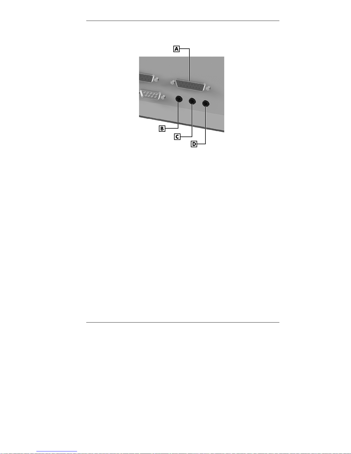
Audio connectors — desktop models
A – MIDI / Game Port B – Line Out Jack
C – Line In Jack D – Microphone Jack
Reviewing System Features 1-9
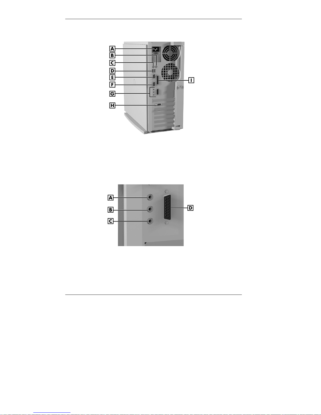
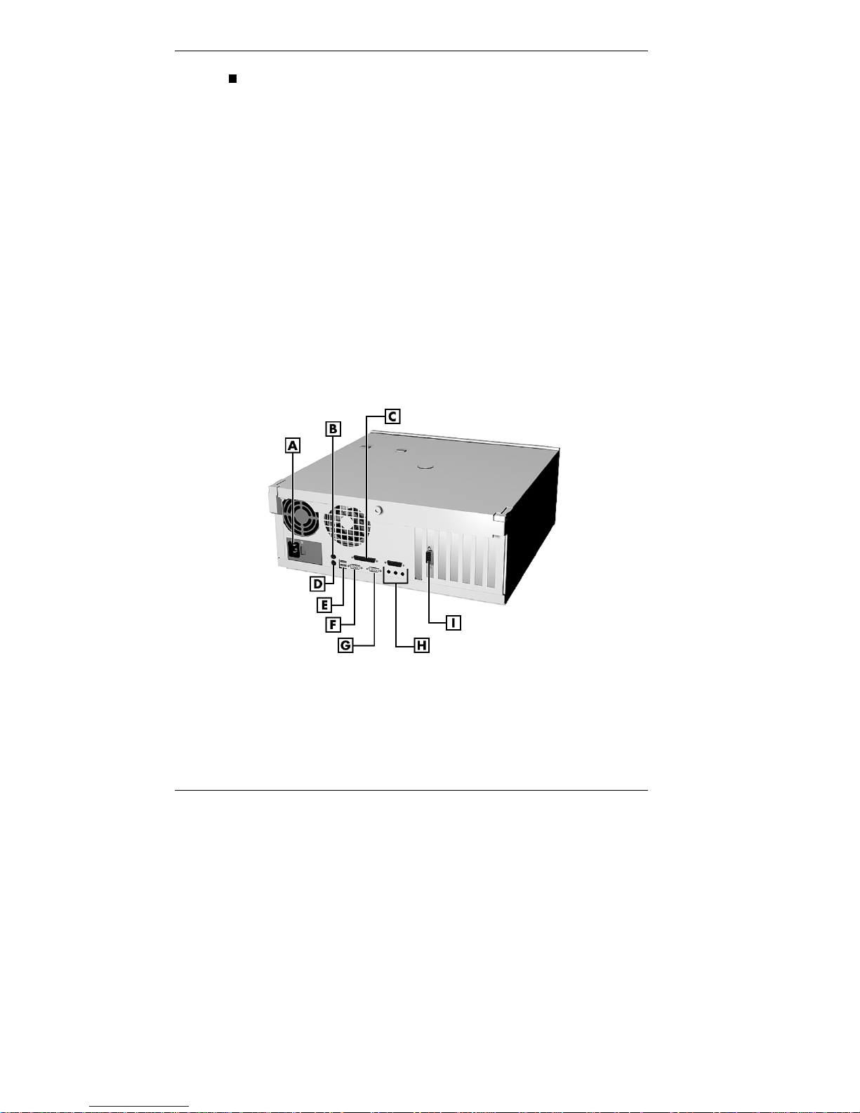
Rear features — minitower models
A – Power Socket B – Mouse Port C – Keyboard Port
D – USB Ports E – Serial Port 1 F – Serial Port 2
G – Audio Connectors H – Video Connector I – Paral lel Port
Audio connectors — minitower models
A – Line Out Jack B – Line In Jack
C – Microphone Jack D – MIDI / Game Port
1-10 Reviewing System Features

External Connectors
Your peripheral compone nt s attach to connectors on the back
of your computer. This is where you connect the monitor,
keyboard, mouse, speakers, and printer.
Your system might have additional
Note:
boards not shown in the prev ious figures. Boards
and board locations v ar y dependi ng on the
model and options you purchased.
Keyboard port
Connect the keyboard that comes with your computer to
this port. The keyboard port supports a personal system
(PS)/2®-compatible, 104-key keyboard with a 6-pin mini
DIN connector.
Mouse port
Attach the mouse that co mes w ith your co mputer to this
port. The mouse port supports a PS/2-compat ible mouse.
Parallel port
Use this port to connect a parallel printer with a 25-pin
connector to the system.
Serial ports
Attach a serial device with a 9-pin connector to either
serial port. Serial devices include a pointing device, serial
printer, or modem.
Universal serial bus (USB) p orts
Use these ports to co nnect a wide range o f new USB
devices, such as printer s, mice, jo ysticks, keyboards, and
telecommunicat ion devices. The speed varies between
12 megabits per second (Mbps) for printers and 1.5 Mbps
for mice and keyboards. You can daisy chain up to
127 devices using USB ports.
Reviewing System Features 1-11

Audio connectors
The audio connector s include line out , line in, and
microphone in jacks, and a MIDI /g ame port.
The line out jack connects powered speaker s and other
powered output devices.
The line in jack connects ster eo audio devices, such as
an amplif ier o r a casse tte or minidisc player for
playback or recording.
The microphone in jack connects a microphone or
telephone headset . Connect the microphone that comes
with your system to this jack.
The MIDI/game port lets you attach a digital musica l
in strument for crea ting yo ur own music al instrument
digital interface (MIDI ) files o r a joyst ick or gamepad
for playing games. Connect t he Microsoft
®
SideWinder™ to this port.
Video connector
Attach the signal cable from your monitor to this
connector. This connection supports an NEC C or
VistaScan ™ series monitor or other video graphics array
(VGA)-compatible monitor with a 15-pin connector.
Your system comes with integrat ed
Note:
Accelerated Graphics Port (AGP) capabilities.
AGP is a new high-perform anc e interface for
graphics-int ensive applications, such as 3-D
applicati ons.
1-12 Reviewing System Features

Modem ports (some models)
Some mo dels come with a fax/data mod em or a
fax/data/voice modem. The modem allows t he co nnect ion
of a phone line to the computer for fax, data
communications, and speakerp hone functions. This is your
connection to infor mat ion serv ices worldwide.
See the modem documentation that co mes with your
system to connect and use your modem.
Power Supply
The system power supply has the following features.
Pow er supply fan
Keep this area clear for proper ventilation. The power
supply fan cools syste m co mponent s and prevent s them
from overheating.
Voltage selector switch
Sets the voltage for your system to 115 volts or 230 volts.
Set the switch corr ectly for the voltage in your
area. Most wall outl ets in the United States and
Canada are 115 volts.
Zip Drive
Some models com e with an Io mega® Zip® drive. The Zip
drive lets you expand the storage capac ity of your hard drive
quickly and easily, 100 megabytes (MB) at a time.
!
CAUTION
Reviewing System Features 1-13
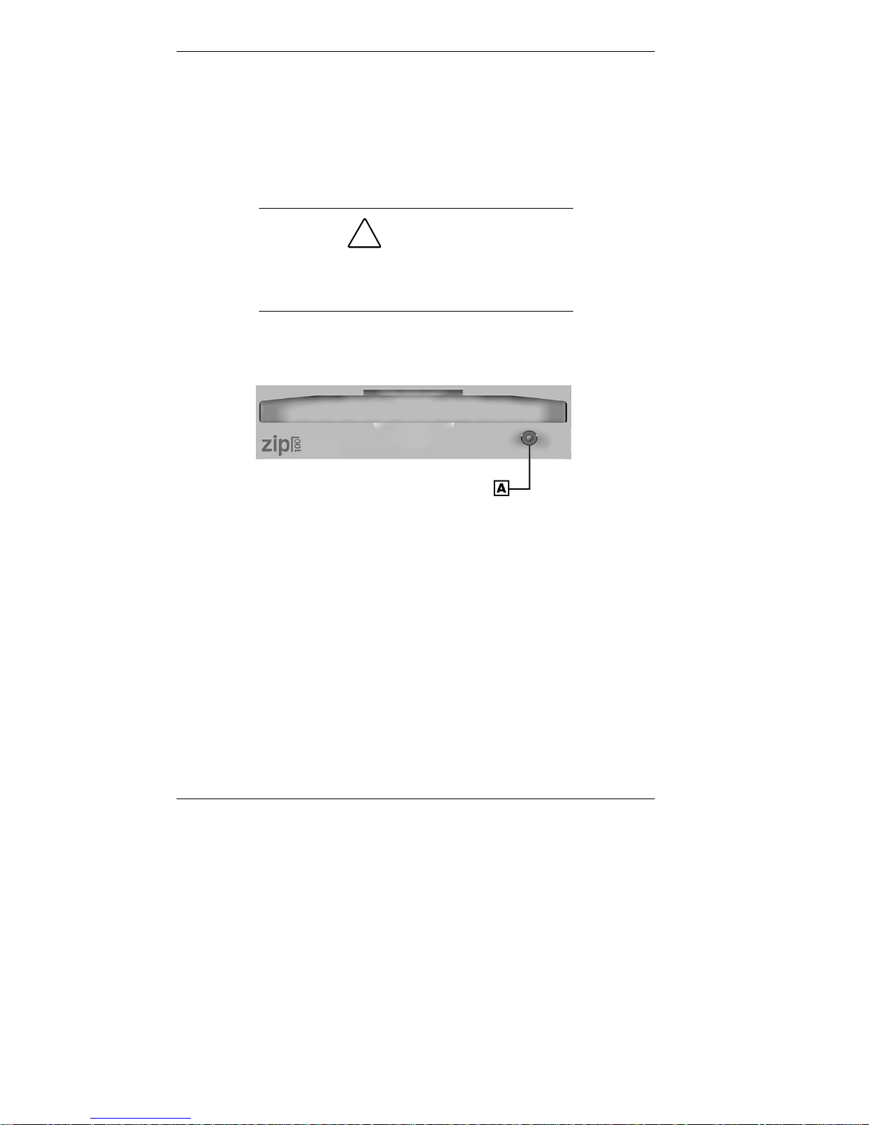
Use the Zip drive to back up work, archive old files and
email, organize your work, transport your work, and more.
With 100-MB Zip disks, you get an unlimited storage
capacity. The Zip drive features include a re lease button/data
lamp. Press th is button to release a Zip disk from the drive.
The d ata lamp lights to indicate d rive activity o r status.
!
CAUTION
To prevent damage to your Zip drive and data,
do not turn off the system or remov e a Zip disk
while the data lamp is lit.
Zip drive features (on Zip models only)
A
– Release Button/Data Lamp
Speakers
Your system’s integrated audio components include support
for optional high-quality, stereo speakers. If you ordered
speakers, see the do cumentation that comes with the speakers
to set them up and to adjust sound. See “Back Features”
earlier in this chapter to locate audio connecto r s and for a
description of the connectors.
1-14 Reviewing System Features
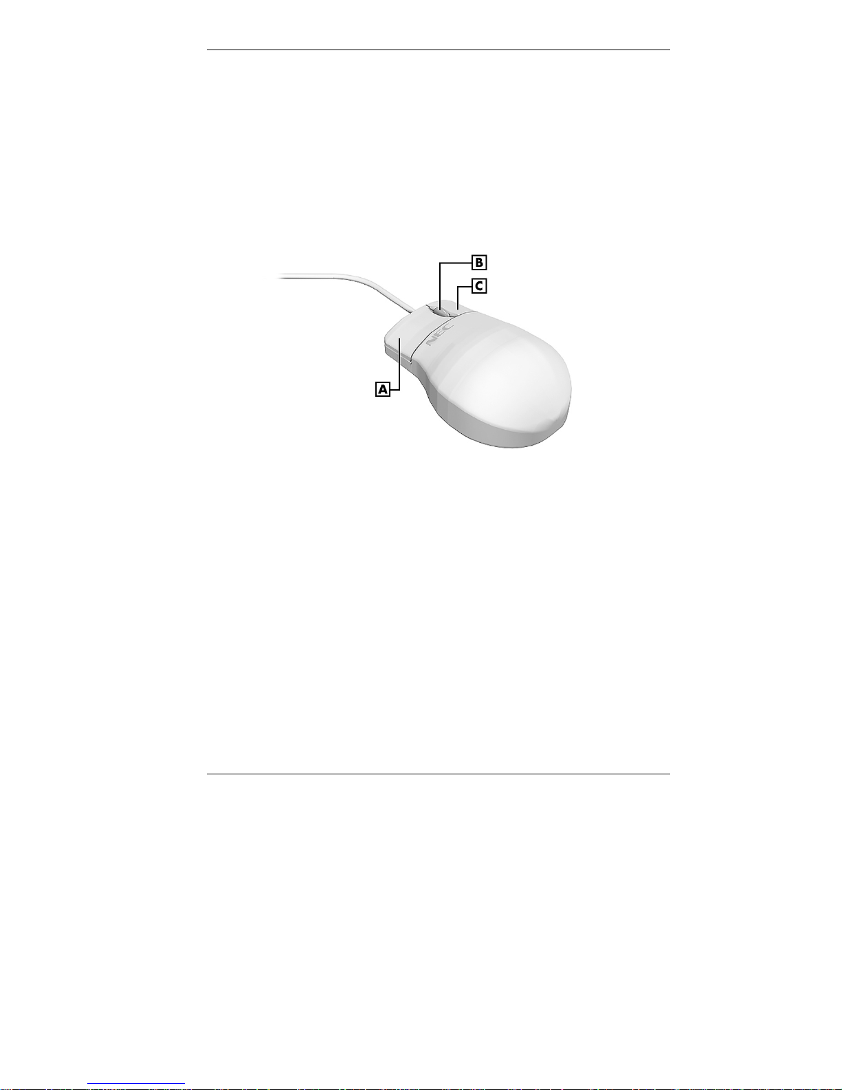
Mouse
In addition to the right and left mouse buttons, your mouse
features a cursor movement wheel. The cursor movement
whee l lets you scr o ll ver t ic a l l y and ho r izo nta lly a nd zoo m in
to view data on the screen.
A – Left Mouse Button B – Cursor Movem ent Wh eel
C – Right Mouse Button
Mouse features
Microphone
All systems come with a micro pho ne. Use it to record vo ice
and sound into your audio files.
Reviewing System Features 1-15

2
Using Your Computer
System Operation
Productivity
Display P roperti es
System Care
Online Documentation
Where to Go From Here

This chapter provides the infor mation you need to start
using your computer.
Check the additional documentation
Note:
that comes with your comput er for information
about using your monitor , speakers, sound
board, graphics board, and any other devices
that you purchased (such as a fax /data/voice
modem).
Read Windows Help files for information about
using your mouse and customizing the settings.
System Operation
In this section, you can find the following information:
starting up and shutting down your system
setting the date and time
using system features such as the CD-ROM/DVD drive
using power management and security features.
Starting Up
Press the power button to start up your system. The power
lamp lights green to indicat e that the system is on.
Several configuration messages appear on the screen at
startup. These messages ar e part o f your syste m’s
Power-On Self-Test (POST). Your computer is checking your
hardware for any changes since the last startup. One beep
indicates t hat t he syste m has succes sfully completed t he
power-on test.
2-2 Using Your Computer

Note:
test by pressing the space bar.
If a problem occurs, a series of beeps may so und. I f this
happens repeatedly after powering on, power off the system
and turn to Chapter 6. This chapter prov ides some helpful
hints on obvious system problems.
Note:
indicati ng that system settings have changed,
run Setup (see Chapter 4).
On models loaded with the Windows NT® operating system,
press
Ctrl-Alt-Del
log-on box appears for entering a password .
Shutting Down
Follow these steps to shut down (po wer off) your computer.
You can bypass the POST memory
If t he syst em disp lays a message
when prompted on-screen to do so. The
1.
Save your work. See the documentation that comes with
your application.
2.
Exit the ap pli cat ion pro gram.
3.
Close any open applications. If you have programs in the
taskbar, click on them and close them.
4.
Make sure that the hard drive and diskett e drives are o ff.
If the har d drive lig ht or diskett e drive light is lit, it
indicates that t he drive is in use.
Using Your Computer 2-3

!
CAUTION
To protect the int egri ty of your data, shut down
all applicati ons before turning off the power.
Unless absolutely nec essary, never power off the
system:
• without exiting properly
• when the hard drive light or diskette drive
ligh t is lit.
5.
Click the Start button on the Windows® taskbar, then
highlight and click “Shut Down.” Selecting Shut Do wn
gives you several choices in the pop-up submenu. Click
“Shut down the computer,” then click the
Enter
press
6.
Windows d isplays the message “It’s now safe to t u r n off
to shut down the computer.
Yes
button or
your computer.”
7.
Turn off power to your monitor.
If you are unable to exit using the
Note:
Windows Start button, you can use the power
button on the front of t he system to power off.
Press and hold in the power button for about four
seconds to shut down the system manually.
2-4 Using Your Computer
 Loading...