


PROPRIETARY NOTICE AND LIABILITY DISCLAIMER
The information disclosed in this document, including all designs and related
materials, is the valuable proper ty of NEC Computer Systems Division, Packard
Bell NEC, Inc. (hereinafter “NECCSD”) and/or its licensors. NECCSD and/or its
licensors, as appropriate, reser ve all patent, copyright and other proprietar y rights
to this document, including all design, manufacturing, reproduction, use, and
sales rights thereto, except to the extent said rights are expressly granted to
others.
The NECCSD product(s) discussed in this document ar e warranted in accordan ce
with the terms of the War ranty Statement accompanyin g each product. However,
actual performance of each such product is dependent upon factor s such as system
configuration, customer data, and operator control. Since implementation by
customers of each product may vary, the suitability of specific product
configurations and applications must be determined by the customer and is not
warranted by NECCSD.
To allow for design and specification improvements, the information in this
document is subject to change at any time, without notice. Reproduction of this
document or portions thereof without prior written approval of NECCSD is
prohibited.
FaxFlash is a service mark of NEC CSD, Packard Bell NEC, Inc.
Direction is a trademark of Packard Bell NEC, Inc.
NEC and MultiSync are registered trademarks of NEC Corporation, used under license.
All other product, brand, or trade names used in this publication are the trademarks or registered
trademarks of their respective trademark owners.
First Printing — October 1998
Copyright 1998
NEC Computer Systems Division
Packard Bell NEC, Inc.
1 Packard Bell Way
Sacramento, CA 95828-0903
All Rights Reserved

Contents
Using This Guide
Text Conventions...................................................... xiii
Related Documents ................................................... xiv
1
Introducing Your Computer
Front Features .......................................................... 1-2
System Controls and Lamps................................. 1-3
Diskette Drive A.................................................. 1-4
CD-ROM Reader/DVD Drive.............................. 1-5
Back Features........................................................... 1-7
External Connectors............................................. 1-9
Power Supply Features ............................................. 1-12
Zip Drive.................................................................. 1-12
Speakers................................................................... 1-14
Mouse ...................................................................... 1-14
Using Your Computer
2
System Operation ..................................................... 2-1
Starting Up.......................................................... 2-2
Shutting Down..................................................... 2-3
Setting the Date and Time.................................... 2-4
Using Diskettes.................................................... 2-4
Using CDs........................................................... 2-5
Handling Compact Discs................................. 2-6
Loading a CD................................................. 2-7
Removing a CD .............................................. 2-8
Using Your System’s Audio Functions ................. 2-8
Setting Power Management.................................. 2-8
Protecting Your System ....................................... 2-9
Setting a Password.......................................... 2-9
Using a Password ........................................... 2-10
Productivity.............................................................. 2-11
Contents iii

Saving Your Work............................................... 2-11
Backing Up Your Work ....................................... 2-12
Printing a Document ............................................ 2-12
Display Properties .................................................... 2-13
System Care ............................................................. 2-15
Protecting Your System from Damage.................. 2-15
Keeping Your System in Good Condition ............. 2-16
Moving or Shipping Your System ........................ 2-17
Online Documentation............................................... 2-18
Where to Go from Here............................................. 2-18
Understanding System Features
3
Standard Features ..................................................... 3-1
System Chassis......................................................... 3-2
System Board Components ....................................... 3-2
Processor............................................................. 3-2
Drive Interfaces ................................................... 3-2
Ports.................................................................... 3-3
System Memory................................................... 3-3
Intel Xcelerator Multifunction Controller.............. 3-3
Flash ROM.......................................................... 3-3
Plug and Play ...................................................... 3-4
Graphics and Multimedia Features....................... 3-4
Accelerated Graphics Port (AGP) Interface .... 3-4
Video Support ................................................ 3-5
Audio ............................................................. 3-5
Super I/O Controller ............................................ 3-5
USB Ports ........................................................... 3-6
Dual IDE Channels.............................................. 3-6
Power-Saving Feature.......................................... 3-6
Options and Upgrades............................................... 3-7
Network Interface Card........................................ 3-7
Modem................................................................ 3-7
Removable Storage.............................................. 3-7
Keyboard............................................................. 3-8
Video................................................................... 3-8
Audio .................................................................. 3-8
iv Contents

4
System BIOS and Utilities
System BIOS and the Setup Utility............................ 4-1
The Setup Utility ................................................. 4-2
When to Use Setup ......................................... 4-2
How to Start Setup ......................................... 4-3
How to Use Setup........................................... 4-3
Maintenance Menu .............................................. 4-4
Main Menu.......................................................... 4-4
Advanced Menu................................................... 4-7
Peripheral Configuration Submenu.................. 4-8
IDE Configuration Submenu........................... 4-10
Floppy Options Submenu................................ 4-13
DMI Event Logging Submenu......................... 4-14
Video Configuration Submenu ........................ 4-15
Resource Configuration Submenu ................... 4-15
Security Menu ..................................................... 4-17
How to Set a Password ................................... 4-18
How to Disable Password Protection............... 4-19
Power Menu ........................................................ 4-20
Boot Menu........................................................... 4-22
Hard Drive Submenu ...................................... 4-24
Removable Devices Submenu.......................... 4-24
Removable Format Submenu .......................... 4-24
Exit Menu ........................................................... 4-24
BIOS Flash Utility.................................................... 4-26
Video Drivers ........................................................... 4-27
Installing Options
5
Option Installation .................................................... 5-1
Safety Precautions ............................................... 5-2
Cover Removal and Replacement .............................. 5-3
Removing the Access Cover................................. 5-4
Replacing the Access Cover ................................. 5-6
Expansion Boards..................................................... 5-7
Installing an Expansion Board.............................. 5-9
Removing an Expansion Board ............................ 5-12
Contents v

Memory Upgrade...................................................... 5-13
Removing a DIMM.............................................. 5-16
Installing a DIMM............................................... 5-17
Video Upgrade.......................................................... 5-18
Data Storage Devices................................................ 5-19
Locating Device Slots .......................................... 5-19
Preparing the Device............................................ 5-20
Identifying Device Cables .................................... 5-21
Diskette Drive Signal Cable ............................ 5-22
IDE Signal Cables .......................................... 5-23
System Power Cables...................................... 5-24
Cabling Storage Devices ...................................... 5-24
Cabling an IDE Device ................................... 5-25
Cabling an Accessible 5 1/4-Inch Device......... 5-26
Installing Storage Devices.................................... 5-27
Removing the Front Panel ............................... 5-28
Installing a 3 1/2-Inch Device.......................... 5-29
Installing the 5 1/4-Inch Device....................... 5-34
Accessing the CD-ROM Reader/DVD Drive... 5-36
Replacing the Front Panel ............................... 5-36
External Options....................................................... 5-37
Connecting a Parallel Printer................................ 5-37
Connecting a Serial Device .................................. 5-38
Setting System Board Jumpers
6
Locating the Jumper.................................................. 6-1
Clearing Your Password ........................................... 6-2
Recovering the BIOS ................................................ 6-4
24-Hour Information Services
7
NECCSD Web Site .................................................. 7-2
NECCSD FTP Site................................................... 7-3
NECCSD FaxFlash Service ...................................... 7-3
NECCSD Bulletin Board Service.............................. 7-5
E-Mail/Fax Technical Support Service...................... 7-7
NECCSD Technical Support Services....................... 7-8
vi Contents

8 If You Have a Problem
Problem Checklist..................................................... 8-2
Solutions to Common Problems................................. 8-3
System Problems ................................................. 8-3
Diskette Drive Problems ...................................... 8-5
Monitor Problems................................................ 8-6
Keyboard/Mouse Problems .................................. 8-7
CD-ROM Reader/DVD Drive Problems............... 8-7
Speaker Problems ................................................ 8-8
Microphone Problems .......................................... 8-8
Getting Help ............................................................. 8-8
Getting Help from Your Company........................ 8-9
Getting Help from Your NECCSD Dealer............ 8-9
Getting Help from NECCSD Technical Support... 8-9
NECCSD Warranty/Non-Warranty
Repair Service.................................................. 8-10
Battery Replacement................................................. 8-10
Setting Up a Healthy Work Environment
A
Making Your Computer Work for You...................... A-1
Arrange Your Equipment .......................................... A-3
Adjust Your Chair .................................................... A-4
Adjust Your Input Devices........................................ A-6
Adjust Your Monitor ................................................ A-8
Vary Your Workday ................................................. A-10
Preexisting Conditions and Psychosocial Factors....... A-11
Checking Your Comfort: How Do You Measure Up? A-12
Checking Your Chair ........................................... A-12
Checking Your Keyboard..................................... A-12
Checking Your Mouse ......................................... A-12
Checking Your Monitor ....................................... A-12
Checking You...................................................... A-13
System Specifications
B
Standard Features ..................................................... B-1
Processor............................................................. B-1
Contents vii

Second Level Cache............................................. B-2
Memory............................................................... B-2
Chipset................................................................ B-5
Intel 82443BX PCI/AGP Controller (PAC)..... B-5
Intel 82371EB PCI ISa IDE
Xccelerator (PIIX4E).................................... B-6
Accelerated Graphics Port (AGP).................... B-8
Universal Serial Bus (USB) Support .................... B-8
IDE Support ........................................................ B-9
Super I/O Controller ............................................ B-9
Serial Ports.......................................................... B-9
Parallel Port......................................................... B-10
Diskette Drive Controller ..................................... B-10
Keyboard and Mouse........................................... B-10
Interrupt Requests (IRQs).................................... B-11
Audio Support ..................................................... B-12
Crystal Audio Subsystem................................ B-12
Wavetable Synthesizer.................................... B-12
Audio Connectors ........................................... B-12
CD-ROM Audio Connector ............................ B-12
Expansion Slots................................................... B-13
BIOS................................................................... B-13
Video Support and Monitor.................................. B-13
Power Supply ...................................................... B-13
Power Consumption........................................ B-14
DC Voltage .................................................... B-15
Environmental Specifications .................................... B-15
Ambient Temperature .......................................... B-15
Humidity ............................................................. B-15
System Board, Connectors, and Error Messages
C
System Board ........................................................... C-1
Connectors ............................................................... C-2
Rear Panel Connectors......................................... C-3
Internal Connectors.............................................. C-4
Error Messages......................................................... C-6
Beep Codes............................................................... C-10
viii Contents

List of Tables
Quick Reference to Information About
Your Computer....................................................... 2-19
Sample Memory Configurations................................ 5-15
System Board Jumper Settings .................................. 6-2
Acceptable DIMM Options....................................... B-3
Sample Memory Configurations................................ B-4
Interrupt Assignments............................................... B-11
Input Requirements................................................... B-13
Output DC Load Requirements................................. B-14
System Board External Connectors ........................... C-3
System Board Internal Connectors............................. C-4
Beep Codes............................................................... C-11
Contents ix

Using This Guide
The NEC Direction SP B-Series User’s Guide provides a
quick reference to information about your computer.
This guide contains the following information:
Chapter 1, Introducing Your Computer, provides a look
at system components. See this chapter to familiarize
yourself with your system.
Chapter 2, Using Your Computer, explains how to start
up and shut down your system, use your system
components, and care for your system.
Chapter 3, Understanding System Features, provides a
quick overview of the various features of your system.
Chapter 4, System BIOS and Utilities, describes the
system BIOS Setup utility program and other utilities
you can use to configure your system. This chapter
provides detailed information about BIOS settings,
including security and power management parameters.
Chapter 5, Installing Options, provides installation
instructions and in some cases, removal procedures for
the options.
Chapter 6, Setting System Board Jumpers, provides
information on changing jumper settings when
reconfiguring your system.
Chapter 7, 24-Hour Information Services, lists the
services available to you for information and help, and
describes how to access the services.
Using This Guide xi
Chapter 8, If You Have a Problem, contains
troubleshooting tips for solving simple problems and
provides information on where you can find help when
you cannot solve a problem yourself.
Appendix A, Setting Up a Healthy Work Environment,
contains guidelines to help you use your computer
productively and safely. This appendix also instructs
you on how to set up and use your computer to reduce
your risk of developing nerve, muscle, or tendon
disorders.
!
Prolonged or improper use of a computer
workstation may pose a risk of serious injury. To
reduce your risk of injury, set up and use your
computer in the manner described in Appendix A,
Setting Up a Healthy Work Environment.
WARNING
xii Using This Guide
Appendix B, System Specifications, provides a technical
description of your computer and its components.
Appendix C, System Board, Connectors, and Error
Messages provides a technical description of the system
board and connectors. This appendix also describes
system error messages.
TEXT CONVENTIONS
This guide uses the following text conventions.
Warnings, cautions, and notes have the following
meanings:
W arnings alert you t o situations that coul d result in
serious personal injury or loss of life.
Cautions indicate situations that can damage the
hardware or software.
!
WARNING
!
CAUTION
NOTE
Notes give important information about the
material being described.
Names of keyboard keys are printed as they appear on
the keyboard, for example,
Text or keystrokes that you enter appear in boldface
type. For example, press
Filenames are printed in uppercase letters.
Ctrl, Alt
Enter
.
Enter
, or
Using This Guide xiii
.

RELATED DOCUMENTS
In addition to this guide, the following printed
documentation ships with your NEC Direction SP B-Series
system:
NEC Direction SP B-Series Quick Setup
Quick Setup contains information for quickly getting
your system up and running. See this information to set
up the system for the first time.
How Does Your Workplace Measure Up?
This brochure provides information for setting up and
using your computer productively and safely.
Information includes guidelines to reduce the risk of
injury associated with using a computer.
Your system ships with additional documentation depending
on your configuration and any options you selected. See the
documentation specific to devices such as your monitor,
speakers, and video graphics board for detailed information
about them.
In addition to the documentation that ships with the system,
the following documentation is available from NECCSD:
xiv Using This Guide
NEC Direction SP B-Series Service and Reference
Manual
This manual provides information for maintaining,
troubleshooting, and repairing NEC Direction
SP B-Series systems. This guide also includes hardware
and interface information for programmers, engineers,
and others who need to know how the systems are
designed.

NECCSD FaxFlashSM Service
NECCSD FaxFlash is an automated service that sends
the latest information about NECCSD and its products
directly to a fax machine. The service is available
24 hours a day, 7 days a week.
With FaxFlash, you can obtain product literature and
technical information bulletins. By using FaxFlash, you
can be kept up-to-date on the latest technical information
for your system.
See Chapter 7 for information about using FaxFlash.
Using This Guide xv
Introducing Your
1
Computer
!
Prolonged or improper use of a computer
workstation may pose a risk of serious injury. To
reduce your risk of injury, set up and use your
computer in the manner described in Appendix A,
Setting Up a Healthy Work Environment.
Your NEC Direction SP B-Series multimedia computer
comes with state-of-the-art, high-performance components
for delivering years of service. Based on an Intel
Pentium II® processor with MMX™ technology, your
system has the power and speed to tackle all today’s
computing needs and most of tomorrow’s.
After setting up your system, take the time to familiarize
yourself with your computer. This chapter provides a brief
look at the features of your system.
WARNING
®
NOTE
This guide covers both desktop and minitower
models of the NEC Direction SP B-Series system .
Features are identical for desktop and minitower
systems; only their orientation differs.
Introducing Your Computer 1-1
FRONT FEATURES
Daily contact with your system is through the controls on
the front panel. The following figures show the control
features on the front of the system.
1-2 Introducing Your Computer
Front features — desktop models
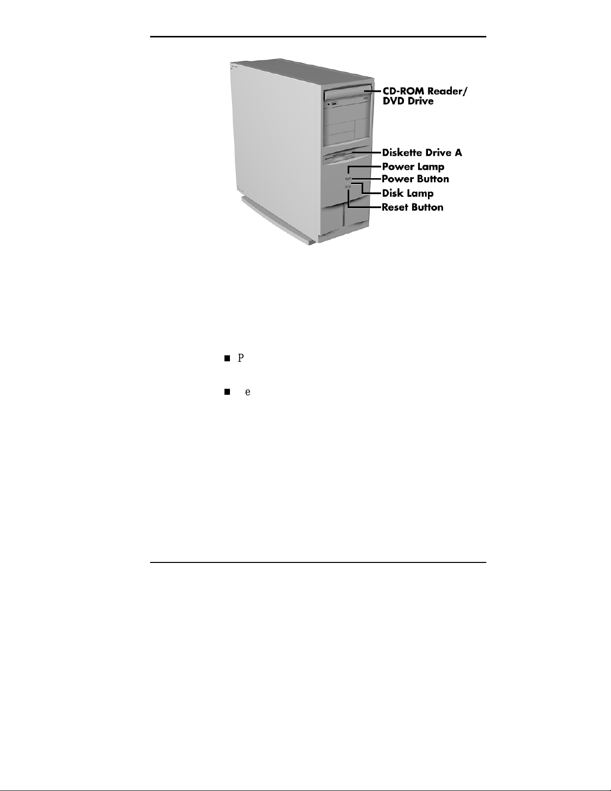
Front panel features — minitower models
System Controls and Lamps
System controls let you select specific system operations;
the lamps let you know the status of system operation. Your
computer has the following controls and lamps:
Power button
Turns the system on and off.
Reset button
Lets you restart your system manually when it does not
respond to keyboard commands.
Introducing Your Computer 1-3
!
Resetti ng your system can resul t i n t he loss of dat a.
Press the reset button only when all other methods
of restarting your computer fail.
System power lamp
Lights when the system is turned on.
Disk lamp
Lights when the hard disk drive is active, reading or
writing data.
Do not turn off the system, unless absolutely
necessary, while the di sk lamp is lit . To do so can
damage your hard disk or data.
CAUTION
!
CAUTION
Diskette Drive A
Your diskette drive has the following features:
Diskette drive busy lamp
Lights when the diskette drive is active, reading or
writing data on a diskette.
To prev ent damage to y our di skette dr iv e and data,
do not turn off the system or remove a diskette
while the diskette drive busy lamp is lit.
1-4 Introducing Your Computer
!
CAUTION
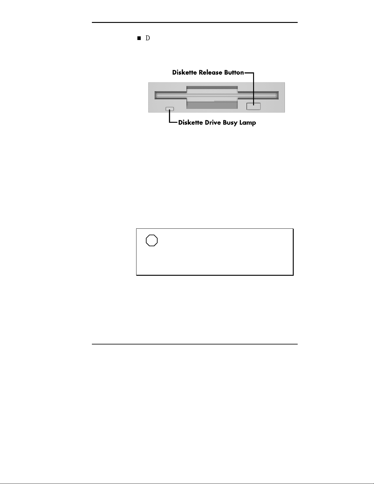
Diskette drive eject button
Lets you remove a diskette from the diskette drive.
CD-ROM Reader/DVD Drive
Your computer comes with a high-speed ATAPI CD-ROM
reader or a DVD drive. The CD-ROM reader/DVD drive
operates at different speeds depending on whether the CD
you are using contains data or music. High-speed operation
lets you get your data faster and see smoother animation
and video.
Diskette drive features
NOTE
The CD-ROM reader/DVD drive in your
system might look di fferent from the one shown in
the fol lowing figure. T he features depend upon t he
model you purchased.
Introducing Your Computer 1-5
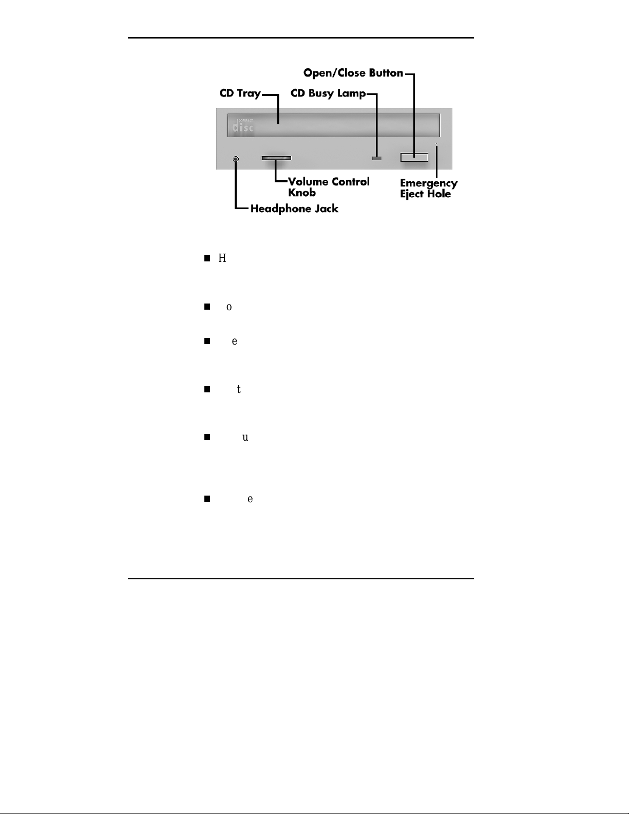
CD-ROM reader/DVD drive features
Headphone jack
Allows the connection of an optional set of stereo
headphones through a mini-jack plug.
Volume control knob
Controls the volume of the optional headphones.
Open/close button
Opens and closes the CD tray. Press this button when
the computer power is on to insert or remove a CD.
CD tray
Provides a surface for loading a CD into the reader.
Press the open/close button to open or close the CD tray.
CD busy lamp
Lights when reader is retrieving data, music, or
graphics/audio from a CD. Do not eject the CD or turn
off the system when the lamp is on.
Emergency eject hole
Allows you to remove a CD manually if normal methods
fail with the open/close button or through sound
software.
1-6 Introducing Your Computer
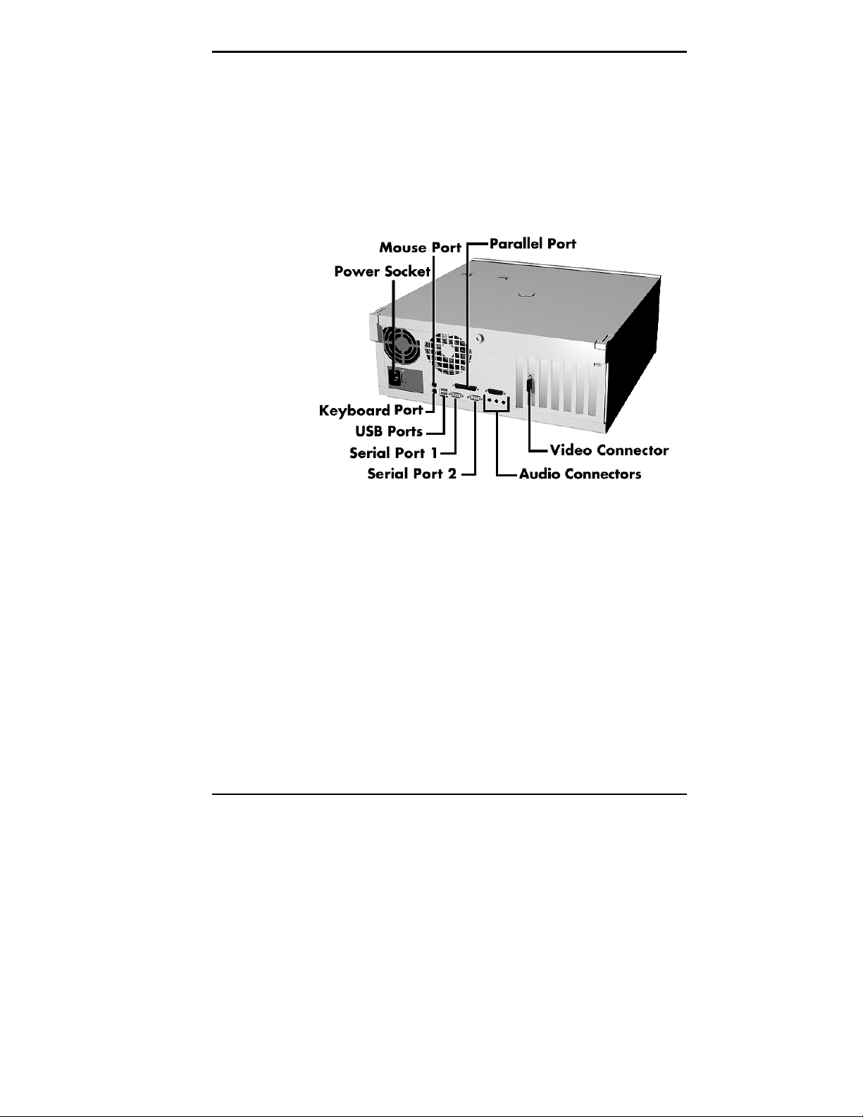
BACK FEATURES
Setting up your system is mainly done through external
connectors on the back of the computer. The following
figures show these connectors.
Note that the minitower and desktop models differ only in
orientation.
Rear features — desktop models
Introducing Your Computer 1-7
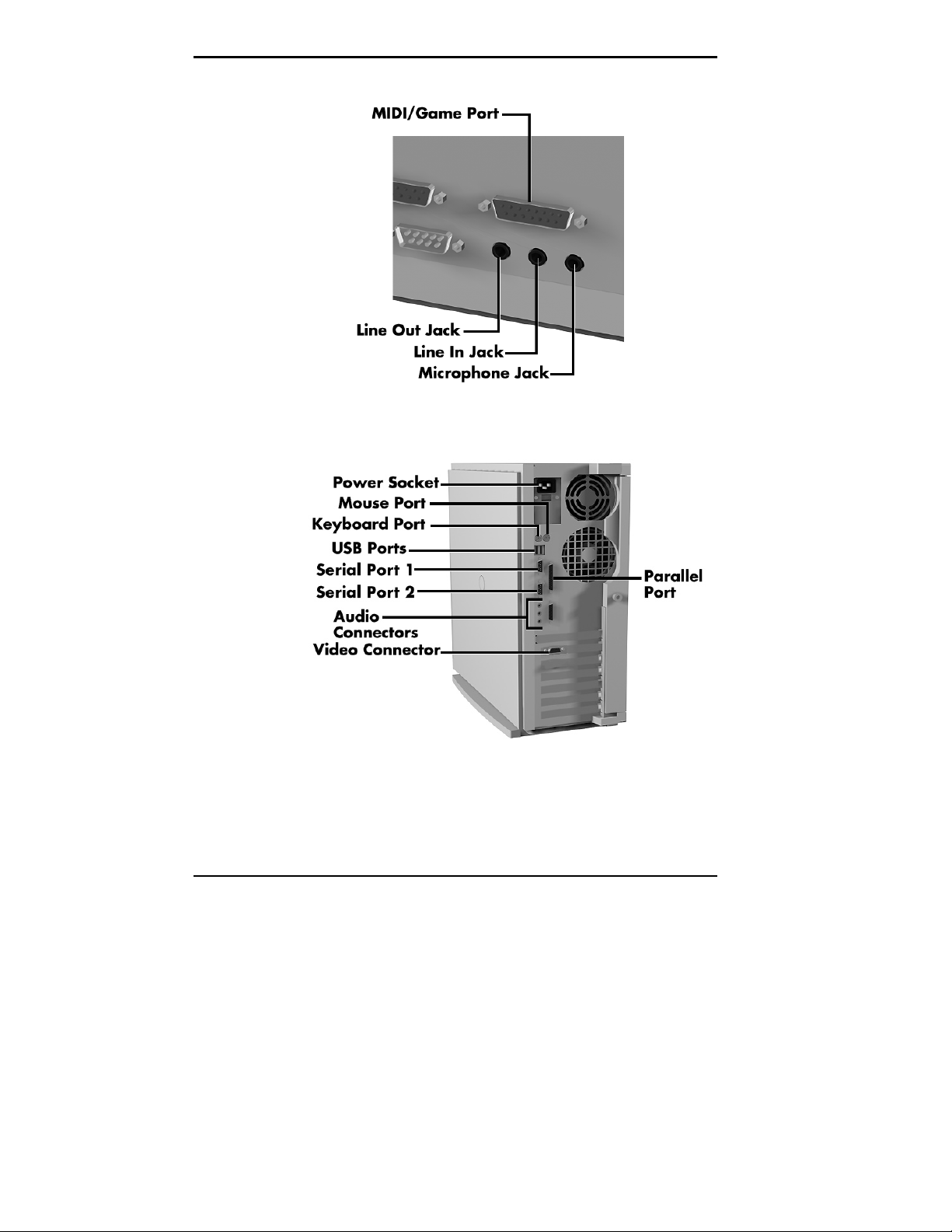
Audio connectors — desktop models
1-8 Introducing Your Computer
Rear features — minitower models
External Connectors
Your peripheral components attach to connectors on the
back of your computer. This is where you connect the
monitor, keyboard, mouse, speakers, and printer.
NOTE
shown in the previous figures. Boards and board
locati ons vary dependi ng on the model and opt ions you
purchased.
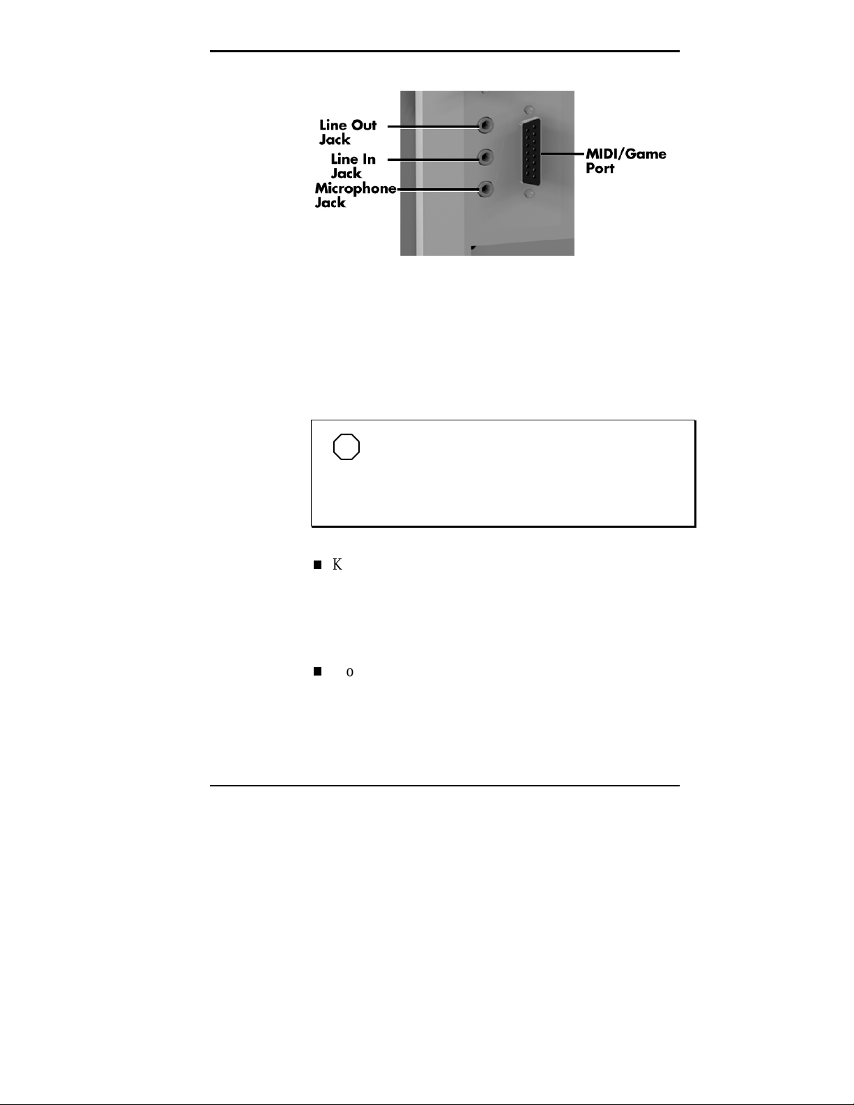
Audio connectors — minitower models
Your system might have additional boards not
Keyboard port
Connect the keyboard that comes with your computer to
this port. The keyboard port supports a personal system
®
(PS)/2
-compatible, 104-key keyboard with a 6-pin
mini DIN connector.
Mouse port
Attach the mouse that comes with your computer to this
port. The mouse port supports a PS/2-compatible
mouse.
Introducing Your Computer 1-9

Parallel port
Use this port to connect a parallel printer with a 25-pin
connector to the system.
Serial ports
Attach a serial device with a 9-pin connector to each
serial port. Serial devices include a pointing device,
serial printer, or modem.
Universal serial bus (USB) ports
Use these ports to connect a wide range of new USB
devices, such as printers, mice, joysticks, keyboards, and
telecommunication devices. The speed varies between
12 megabits per second (Mbps) for printers and
1.5 Mbps for mice and keyboards. You can daisy chain
up to 127 devices using USB ports.
Audio connectors
The audio connectors include line out, line in, and
microphone in jacks, and a MIDI/game port.
The line out jack connects powered speakers and
other powered output devices.
The line in jack connects stereo audio devices, such
as an amplifier or a cassette or minidisc player for
playback or recording.
The microphone in jack connects a microphone or
telephone headset. Connect the microphone that
comes with your system to this jack.
The MIDI/game port lets you attach a digital
musical instrument for creating your own musical
instrument digital interface (MIDI) files or a joystick
or gamepad for playing games.
1-10 Introducing Your Computer
Video connector
Attach the signal cable from your monitor to this
connector. This connection supports an NEC C or CS
series monitor or other video graphics array (VGA)compatible monitor with a 15-pin connector.
The video board in your system depends on your system
configuration. See the documentation that comes with
your computer for detailed information about the board.
NOTE
Your system comes with an Accelerated
Graphics Port (AGP) video board. AGP is a new
high-performance interface for graphics-intensive
applications, such as 3D applications.
SCSI port (SCSI models only)
This port is on the SCSI adapter board that comes
installed in an expansion slot on SCSI models. The Wide
SCSI interface allows connection of up to 15 SCSI
devices. See the documentation that comes with your
computer for information about your SCSI adapter
board.
Fax/modem ports (some models)
Some models come with a fax/data/voice modem board.
The fax/modem allows the connection of a phone line to
the computer for fax, data communications, and
speakerphone functions. This is your connection to
information services worldwide.
See the fax/modem documentation that comes with your
system to connect and use your fax/modem.
Introducing Your Computer 1-11
POWER SUPPLY FEATURES
The system power supply has the following features.
Power supply fan
Keep this area clear for proper ventilation. The power
supply fan cools system components and prevents them
from overheating.
Voltage selector switch
Sets the voltage for your system to 115 volts or 230
volts.
Set the switch correctl y f or the v olt age in your area.
Most wall outlets in the United States and Canada
are 115 volts.
ZIP DRIVE
!
CAUTION
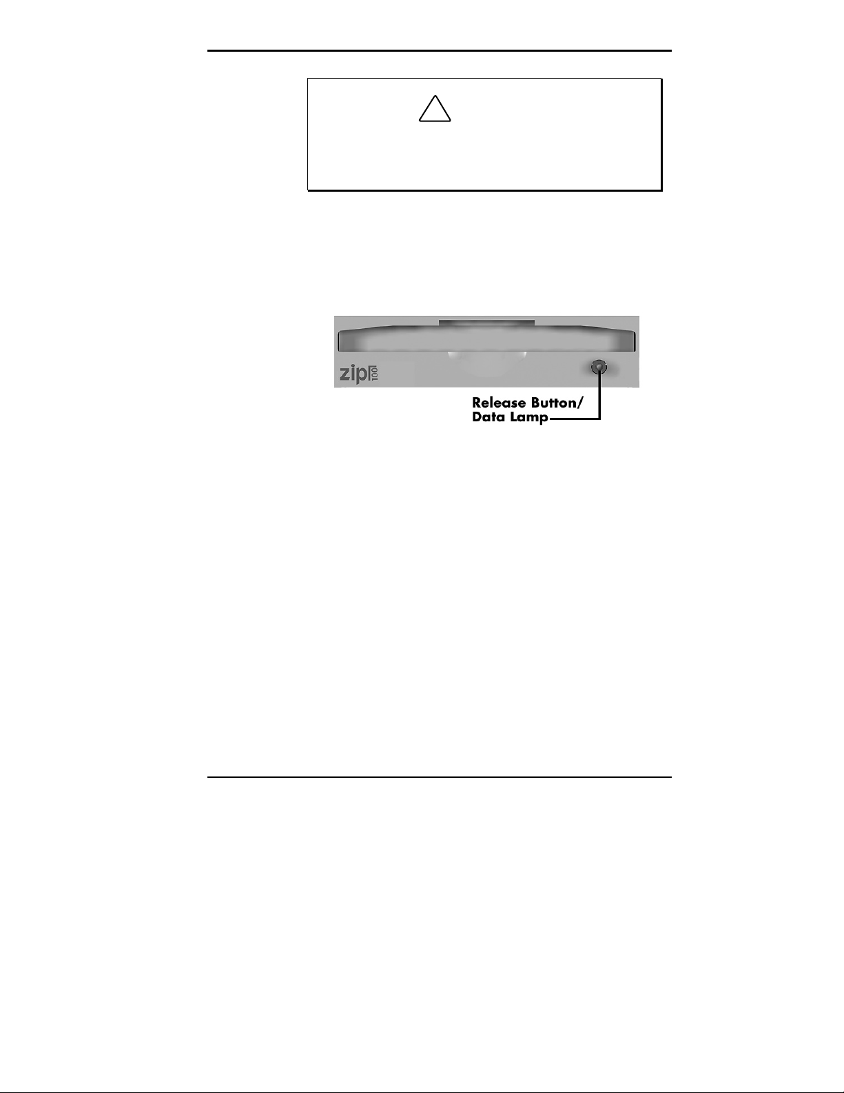
Some models come with an Iomega® Zip™ drive. The Zip
drive lets you expand the storage capacity of your hard disk
quickly and easily, 100 megabytes (MB) at a time.
Use the Zip drive to back up work, archive old files and
email, organize your work, transport your work, and more.
With 100-MB Zip disks, you get an unlimited storage
capacity. The Zip drive features include a release
button/data lamp. Press this button to release a Zip disk
from the drive. The data lamp lights to indicate drive
activity or status.
1-12 Introducing Your Computer
!
To prev ent damage to your Z ip drive and data, do
not turn of f the system or rem ove a Zi p disk while
the data lamp is lit.
CAUTION
Zip drive features (on Zip models only)
Introducing Your Computer 1-13
SPEAKERS
MOUSE
Your system’s integrated audio components include support
for optional high-quality stereo speakers. If you ordered
speakers, see the documentation that comes with your
speakers to set them up and to adjust sound. See “Back
Features” earlier in this chapter to locate audio connectors
and for a description of the connectors.
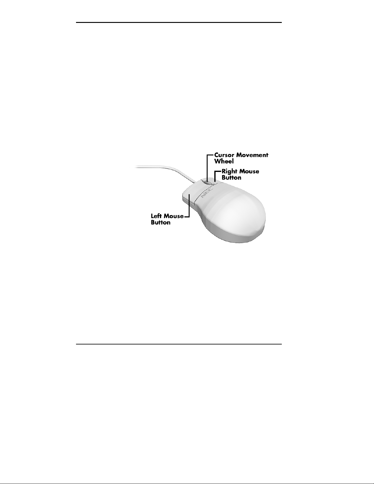
In addition to the right and left mouse buttons, your mouse
features a cursor movement wheel. The cursor movement
wheel lets you scroll vertically and horizontally and zoom in
to view data on the screen.
1-14 Introducing Your Computer
Mouse features
2
Using Your Computer
This chapter provides the information you need to start
using your computer. Information includes:
System operation
Productivity
Video display properties
System care
Moving or shipping your system
Online documentation.
NOTE
Check the additional documentation that
comes with your computer for information about
using your monitor, speakers, graphics board, and
any other devices that you purchased (such as a
fax/data/voice modem).
Read Windows Help files for information about
using your mouse and customizing the settings.
SYSTEM OPERATION
In this section, you can find the following information:
starting up and shutting down your system
setting the date and time
Using Your Computer 2-1
Starting Up
using system features such as the CD-ROM
reader/DVD drive
using power management and security features.
Press the power button to start up your system. The power
lamp lights green to indicate that the system is on.
Several configuration messages appear on the screen at
startup. These messages are part of your system’s
Power-On Self-Test (POST). Your computer is checking
your hardware for any changes since the last startup. One
beep indicates that the system has successfully completed
the power-on test.
NOTE
You can bypass the POST memory test by
pressing the space bar.
If a problem occurs, a series of beeps may sound. If this
happens repeatedly after powering on, power off the system
and turn to Chapter 8. This chapter provides some helpful
hints on obvious system problems.
NOTE
that system sett ings have changed, run Setup (see
Chapter 4).
On models loaded with the Windows NT® operating
system, press
so. The log-on box appears for entering a password.
2-2 Using Your Computer
If the system displays a message indicating
Ctrl-Alt-Del
when prompted on-screen to do
Shutting Down
Follow these steps to shut down (power off) your computer.
1.
2.
3.
4.
Save your work. See the documentation that comes with
your application.
Exit the application program.
Close any open applications. If you have programs in
the taskbar, click on them and close them.
Make sure that the hard drive and diskette drives are off.
If the hard drive light or diskette drive light is lit, it
indicates that the drive is in use.
!
To protect the i ntegrity of your data, shut down all
applications before turning off the power. Unless
absolutely necessary, never power off the system:
• without exiting properly
CAUTION
• when the hard drive light or diskette drive
light is lit.
5.
Click the Start button on the Windows® taskbar, then
highlight and click “Shut Down.” Selecting Shut Down
gives you several choices in the pop-up submenu. Click
Yes
“Shut down the computer,” then click the
Enter
press
6.
Windows displays the message “It’s now safe to turn off
to shut down the computer.
button or
your computer.”
7.
Turn off power to your monitor.
Using Your Computer 2-3

NOTE
If you are unable to exit using the Windows
Start button, you can use the power button on the
front of t he system to power off. Pr ess and hol d in
the power button f or about ten seconds to shut down
the system manually.
Setting the Date and Time
Use the following steps to set the system date and time from
the Windows desktop.
Double click the system clock on the taskbar.
1.
Set the time by entering the current hour, minutes, and
2.
seconds in the appropriate fields, hh:mm:ss. Move from
field to field with the Tab key or Shift-tab to move from
right to left.
Set the date by entering the month and year in
3.
appropriate fields. To select the day, click on the
numeric day of the calendar.
Using Diskettes
Follow these steps to insert a 3.5-inch diskette in the
standard diskette drive.
Holding the diskette at its top edge, insert it into the
1.
diskette drive:
Insert the diskette all the way into the drive until you
2.
hear a click.
2-4 Using Your Computer
label side facing right in desktop systems.
label side up in minitower systems.

NOTE
If your diskette did not come formatted, you
must f ormat it bef ore storing inf ormati on on it. See
your operating system documentation for
information about formatting a diskette.
!
Do not f ormat your hard dr ive. F ormatti ng the hard
drive erases all preinstalled applications.
CAUTION
To remove a diskette from the diskette drive, press the
release button on the 3.5-inch diskette drive.
Do not remove a diskette from the drive when the
diskette drive lamp is lit. To do so can damage both the
data on the diskette and the drive.
Using CDs
Do not turn off the system power while the diskette is
being accessed.
Do not reset the system (except as a last resort) when the
diskette drive is in use.
See the following sections for information about handling,
loading, and removing CDs.
Using Your Computer 2-5

Handling Compact Discs
To protect your CDs from damage, use the following
guidelines when you handle them.
Always pick up the disc by its edges.
Do not touch the surfaces of the disc. Handle it by the
edges and, if necessary, by putting your finger through
the hole.
Do not write on or apply labels to either side of the disc.
Keep the disc away from direct sunlight or high
temperatures. Clean fingerprints or dust from the disc by
wiping it with a soft dry cloth.
Gently, brush the cloth from the center of the disc
toward the edge.
2-6 Using Your Computer
Handling a CD

Cleaning a CD
!
Do NOT use benzene, paint thi nner, recor d cleaner,
static repellent, or any other chem ical on the disc.
Chemicals and cleaners can damage the disc.
CAUTION
Loading a CD
To insert a CD into the CD-ROM reader/DVD drive,
follow these steps:
1.
Press the open/close button. A CD tray slides out from
the reader/drive.
2.
Remove the CD from its protective case. Hold the CD
by its center hole and outer edges to avoid touching its
surface.
3.
Place the CD, printed side up, into the circular area of
the tray.
4.
Press the open/close button again. The reader/drive
automatically slides into the tray.
Using Your Computer 2-7

Removing a CD
To remove a CD, simply press the open/close button and
remove the CD when the tray slides out. Press the
open/close button again to close the tray.
Using Your System’s Audio Functions
Multimedia systems come with all the audio functions and
components you need to produce fine stereo output. See the
separate documentation included with these devices.
The integrated audio components in multimedia systems
provide support for industry sound standards including
Sound Blaster™ , Windows Sound System™, and
MPU-401 to provide all the functionality required for your
multimedia applications.
Setting Power Management
Your system provides an energy-saving Advanced Power
Management feature, which reduces power consumption
when your computer is idle. You can set the length of this
idle time in your system’s Setup utility.
Enter the Setup utility by pressing F2 when the
1.
following bootup message appears.
The Main menu appears. Use your right arrow key to
2.
select the Power menu. The Power Management option
is factory set to “Enabled.”
Press
3.
box appears.
Follow the on-screen prompts to change the options.
4.
You can set the Inactivity Timer for up to a 16-minute
delay.
Use the up and right arrow keys to select Exit.
5.
2-8 Using Your Computer
Press <F2> to enter SETUP
to select Power Management. A submenu
Enter

Select “Exit Saving Changes.” Press
6.
At the prompt, to confirm exiting setup, press
7.
Exit the Setup utility.
NOTE
When you want to resume work after your
computer has entered power-saving mode, just
move your mouse or press a key, and your
computer is active again.
Protecting Your System
Your system’s security features provide protection against
unauthorized access to your system and data. This
protection includes a user and supervisor password.
Dual password security provides two levels of password
security. A “Supervisor password” allows access to the
system’s Setup utility for system configuration. A “User
password” allows system bootup only after the entry of a
password.
Enter
.
Enter
.
When you start up your system for the first time, you are
asked to enter a system password. The following section
explains the password procedure.
Setting a Password
Use the following procedure to set a password.
Turn on or reboot your system. Setup displays the
1.
following message:
Press F2. Setup’s Main menu appears.
2.
Using your arrow keys, select Security from the menu
3.
bar. The Security menu appears.
Press <F2> to enter SETUP
Using Your Computer 2-9

Select “Set Supervisor Password” or “Set User
4.
Password” with the arrow keys and press
NOTE
Enabling the Supervisor Password feature
requires that a password be entered before ent ering
the Setup Utility.
Enter
.
Setup displays a dialog box with the following
prompts:
Enter new password: [ ]
Confirm new password: [ ]
Type your password and press
5.
case-sensitive. Reenter your password and press
again.
Use the arrow keys to select Exit.
6.
Select “Exit Saving Changes.” Press
7.
At the prompt, to confirm exiting setup, press
8.
Your password takes effect the next time you power on
the system. You must enter a password the next time
you power on.
Using a Password
After you set your password in Setup and reboot the
system, a password prompt appears each time you power on
the system.
To use your password, type the password at the password
prompt and press
Enter
. Passwords are not
Enter
Enter
.
Enter
.
Enter
.
2-10 Using Your Computer

NOTE
appear on your screen. Enter your password
carefully.
If you enter the password incorrectly, your system does not
boot. You have three chances to enter the correct password.
After the third unsuccessful attempt, you must reboot your
system and try again.
PRODUCTIVITY
The following sections explain how to use your system to
maximize your productivity.
Saving Your Work
Save your work often! The time you take to periodically
save your data file as you work can save you time in the
end! By doing so, you can avoid losing a whole day’s work
or more when the unexpected happens, such as losing power
due to a power outage.
For security, characters you enter do not
Some applications provide automatic save options for
specified intervals of time as you work. For example, you
might want to save your work every 10 minutes. This
reduces the amount of lost information should you lose
power or experience some other problem.
In Windows programs, you can select a Save option from
the File menu. If you are creating a new file, you’ll need to
specify a name for your file and a location to store it (drive
and directory).
Always save your work before you exit an application. See
the application’s documentation for available save options.
Using Your Computer 2-11

Backing Up Your Work
Back up your work on a regular basis! Backup procedures
are important for the efficient and effective use of your
computer. Protect your program and data files with regular
backup procedures.
Make backup copies of your program and data files that are
on diskette and on the hard drive.
The standard practice for diskette backup is to copy each
diskette, store the original in a safe place, and use the copy
as your working diskette. See your operating system
documentation for information about copying diskettes. Use
your Zip drive or Ditto tape backup unit (if installed) to
back up your files.
Printing a Document
Before you can print out a document, you must
connect a printer to your computer
set up the printer.
If you have not connected a printer, see “Connecting a
Parallel Printer” in Chapter 5.
If you did not choose a printer when you initially set up
your computer, you’ll need to do that before you can print
(see your Windows documentation). If you are using a
non-Windows program, you’ll need to set up a printer
driver for that program. See your printer documentation for
printer setup information.
Once your program is set up to work with your printer,
printing a file within a Windows application is easy:
Turn on your printer power.
1.
2-12 Using Your Computer

Be sure you have paper in your printer. See your printer
2.
documentation to load paper.
Check that the printer is “online” or “selected.” See your
3.
printer documentation for information about choosing
the online mode.
Select “Print” from the File menu of your Windows
4.
application. A Print dialog box appears.
Select how many print copies you want and the range of
5.
pages. To print one copy of all the pages, simply click
“OK.”
DISPLAY PROPERTIES
The following procedure describes how to load video
drivers to change the properties of your display. The display
properties that you can set include the screen resolution, the
number of colors displayed, and the video refresh rate.
For information about the resolutions, colors, and refresh
rates supported by your video drivers, see the separate
documentation that describes your video adapter.
NOTE
If your monitor is flickering or you change
your moni tor, check that the Moni t or ty pe param eter
is set correctly for your monitor.
From the Windows desktop, press the right mouse
1.
button and click on Properties.
The Display Properties window appears. Select the
2.
Settings tab.
Using Your Computer 2-13

NOTE
The appearance of your desktop may vary
slightly from the one shown.
NOTE
palette were set at the factory for optimum
perform ance. Before you change t hese settings, be
sure that your monitor and video adapter support
the new settings.
2-14 Using Your Computer
Display Properties Window
Both the screen resolution and the color

3.
4.
5.
SYSTEM CARE
Your system is a durable, dependable computer built for
heavy use. With protective measures and proper care, you
can prevent problems and promote the successful operation
and long life span of your computer.
Use the slide bar in the Display Area section of the
screen to select the screen resolution.
Select the number of colors you want to display from the
Color Palette section of the screen.
NOTE
If you are using Windows NT, you can click
on List All Modes. You get a list of all the modes
available for your video board.
Click “Apply” to test the new display settings. If you are
sure that the settings are correct, click “OK.”
Protecting Your System from Damage
There are several ways that you can protect your system
from possible damage. NECCSD strongly recommends the
following protective measures:
Connect a surge suppressor between your computer and
a grounded wall outlet. A surge suppressor protects your
system from sudden transient increases and decreases in
electrical power.
Be sure to connect all peripherals, such as your monitor
and printer, to the surge protector. The surge protector
should be the only device that you plug into the wall
outlet.
Using Your Computer 2-15

Avoid repeated power-on cycles. These subject the
system components to temperature variations and stress.
Disconnect your system from telephone and power lines
when an electrical storm threatens. If you have a
fax/modem, lightning can travel in on the phone line and
damage both the fax/modem and the system unit.
Lightning can also travel in on power lines and damage
your monitor and system unit.
Be sure that system power is off before you connect or
disconnect a cable. Never make cable changes when the
system power is on. To do so could damage your system
and its peripherals.
Use Setup options to limit access to your computer (see
“Security Menu” in Chapter 4). Use appropriate virus
detection software regularly to protect your system from
computer viruses.
Keep your computer away from direct sunlight and
extreme hot and cold temperatures.
You can find the operating and non-operating (storage)
temperatures in Appendix B.
After turning off the power, wait about fifteen to thirty
seconds for the hard drive to spin down before you
power on again.
Be sure that nothing is placed on top of your monitor’s
ventilation vents or the system’s power cables.
Prevent dust from entering your system by covering it
when it is not in use.
Keeping Your System in Good Condition
Maintain the condition of your system by periodically
following the general procedures listed next.
2-16 Using Your Computer

!
For safety, turn off and unplug your system,
monitor, and any external dev ices before cleaning
them.
Clean the outside of the computer with a soft clean cloth.
You can remove stubborn stains with a cloth slightly
dampened with a mild detergent. Never use a strong
cleaner or solvent on any part of the system.
Keep food and liquids away from your computer.
Periodically clean the keyboard with a vacuum cleaner
brush attachment. Do not use any liquid cleaners on the
keyboard as they can damage the keyboard.
If an object, such as a paper clip, falls into the keyboard,
turn the keyboard over and gently shake it.
Clean the monitor screen with a glass cleaner and wipe it
with a clean, lint-free cloth. You may use wet/dry
cleaning pads manufactured for monitor screens.
WARNING
Moving or Shipping Your System
Use these steps to prepare your system for moving or
shipping:
1.
Back up your hard drive files onto diskettes, Zip disks,
or tape cartridges.
Be sure to take precautions for storing and transporting
diskettes or cartridges so that they are not exposed to
magnetic fields or electrical impulses.
Using Your Computer 2-17

Remove any diskette from the diskette drive. If you have
2.
a CD in the CD-ROM reader/DVD drive, remove the
CD. If you have a Zip disk in a Zip drive, remove the
disk.
Turn off the system unit and any external options
3.
connected to it.
Unplug the system unit power cable from the wall outlet
4.
or surge suppressor, then from the unit itself.
Unplug any external options from the wall outlets or
5.
surge suppressor, then disconnect them from the system
unit.
Pack the system components in the original shipping
6.
materials and cartons. If these are not available, be sure
to use adequate packing materials to protect the
components.
ONLINE DOCUMENTATION
Most of your application programs include online help at
the touch of a button (usually the Help button). Many
programs also incorporate separate, complete online user’s
guides.
Windows provides extensive online help and “wizards” to
guide you through procedures.
WHERE TO GO FROM HERE
Once you have your system up and running, we suggest that
you install your applications and study the documentation
that comes with them.
See the following quick reference chart to find information
about some of the things you might want to do.
2-18 Using Your Computer

Quick Reference to Information About Your Computer
WHAT YOU WANT TO FIND WHERE TO FIND IT
Basic information about my
computer
Setting a password “Setting a Password” in this chapter
Loading a CD “Loading a CD” in this chapter
Adding options Chapter 5, “Installing Options”
Understanding power
management
Accessing the World Wide
Web
Protecting my system from
viruses
Changing video drivers “Display Properties” in this chapter.
Using support services “24-Hour Information Services,” Chapter 7
Taking care of my system “System Care” in this chapter
Troubleshooting tips “If You Have a Problem,” Chapter 8
“Introducing Your Computer,” Chapter 1
“Power Saving Feature,” Chapter 3, and “Power
Menu,” Chapter 4
“Microsoft Internet Explorer” under Programs in
the Start menu
“VirusScan” and “WebScan” under Programs in
the Start menu
Using Your Computer 2-19

Understanding System
3
STANDARD FEATURES
Features
Your Direction SP B-Series computer is a 350- or
400-MHz Intel
technology and 512 KB of burst pipelined synchronous
cache memory.
All models come with the following features:
3.5-inch, 1.44-MB diskette drive
Memory — 32 to 384 MB of Synchronized Dynamic
Random Access Memory (SDRAM) using Dual In-line
Memory Modules (DIMMs)
A hard disk drive: 4.3-gigabyte (GB), 6.4-GB, 8.4-GB,
9.1-GB, 11.5-GB Ultra DMA/33, or a
9-GB ultra-wide SCSI
CD-ROM reader or DVD drive
®
Pentium® II-based system with MMX
Crystal™ audio subsystem
Accelerated Graphics Port (AGP) video port
NEC palmrest keyboard
Microsoft® IntelliMouse®.
Understanding System Features 3-1

Software installed on the hard disk includes:
Microsoft® Windows NT® or Windows® 95 or
Windows 98
MS Office 97 Small Business Edition
Internet Explorer
Appropriate drivers for your hardware
McAfee® VirusScan®, McAfee WebScan™
Adobe® Acrobat® reader.
SYSTEM CHASSIS
The chassis provides an enclosure for the system board,
power supply, three PCI, one ISA expansion slot, one set of
shared PCI/ISA slots, one specialized slot for the
Accelerated Graphics Port (AGP), and seven storage device
slots (two for hard drives).
SYSTEM BOARD COMPONENTS
Your computer’s system board has the following
components.
Processor
Processing for your system is provided by the Intel
Pentium II microprocessor at speeds of
350 or 400 MHz.
Drive Interfaces
PCI IDE
IDE/ATA (hard disk drives)
ATAPI (CD-ROM readers, DVD drives, tape
backup units, Zip drives)
SCSI (Adaptec)
Fast SCSI, Ultra Wide SCSI
3-2 Understanding System Features

Ports
Your computer’s system board includes the following
connectors on the rear panel:
PS/2-style keyboard and mouse ports
Two Universal Serial Bus (USB) ports
Two serial ports (9-pin “D” style)
One parallel port
Audio — microphone in, line in, line out, MIDI/game
port.
System Memory
Your system’s standard memory configuration is 32 MB to
384 MB, depending upon the model you purchased. You
can expand the memory to a maximum of 384 MB. See
Appendix B for memory upgrade options.
Intel Xcelerator Multifunction Controller
Your computer uses an Intel PIIX4E, which incorporates
the PC-to-ISA bridge, a USB controller, a dual-channel
IDE interface, an enhanced DMA controller, an interrupt
controller, power management, and a real-time clock.
Flash ROM
See Appendix B for the interrupt level assignments (IRQ)
table.
With Flash ROM, a ROM BIOS change:
is fast and easily done using a Flash utility
eliminates the expensive replacement of ROM BIOS
chips, and reduces system maintenance costs
reduces inadvertent system board damage that can take
place when replacing ROMs
Understanding System Features 3-3

facilitates adopting new technology while maintaining
corporate standards
gives network administrators company-wide control of
BIOS revisions.
Information on how to use the Flash utility is provided in
Chapter 4, System BIOS and Utilities.
Plug and Play
The BIOS is Plug and Play. It automatically configures
both PCI and Plug and Play devices. This autoconfiguration
feature allows you to insert or remove a PCI or Plug and
Play ISA add-in card and power up your computer without
complicated setting changes. The system automatically
configures interrupts, I/O space, and other parameters. Any
interrupts set to “Available” in the system Setup can be
used by the Plug and Play board.
Graphics and Multimedia Features
The system provides the following multimedia features.
Accelerated Graphics Port interface (AGP)
The Intel 82443BX PCI/AGP Controller(PAC) supports
3.3 V AGP devices
processor host bus frequencies of 100 MHz and 66 MHz
symmetrical and asymmetrical DRAM addressing
concurrent host, AGP, and PCI transactions to main
memory
System Management Mode (SMM).
3-4 Understanding System Features

Video Support
Audio
Your system comes with an Accelerated Graphics Port
video board installed. For more information about your
video board see its documentation.
Your system’s integrated audio chips, the Crystal
Semiconductor CS4611 3D with CS4236B wavetable, and
optionally the Creative Labs AWE64D Wavetable
Synthesizer, integrates an enhanced stereo controller and a
game port. It provides:
all the digital and analog mixing functions you need to
record and play sound
line, microphone, and monoaural inputs
Plug and Play compatibility
Sound Blaster® and Windows Sound System™
compatibility.
The Wavetable Synthesizer, available on some models,
integrates all the features of the CS4236B with a general
MIDI processor and wavetable ROM, able to generate up to
64 voices simultaneously.
Super I/O Controller
As standard equipment, your system provides the SMC
FDC37C777 Super I/O Controller, an ISA Plug and Play
multifunction I/O device that incorporates:
Two serial ports with
Two UARTS, software compatible with the
NS16C550
Data transfer speeds up to 115.2 Kbits/sec
®
Understanding System Features 3-5

USB Ports
Multimode bidirectional parallel port with
Standard mode compatibility
Enhanced Parallel Port (EPP) mode with driver
support
High-speed Extended Capabilities Port (ECP) mode
Diskette drive controller
Keyboard and mouse controller.
The two Universal Serial Bus (USB) ports allow you to add
serial devices without opening up the system; simply plug
them into the port.
The ports are hot-pluggable: You can plug in a
peripheral without shutting down the computer; the USB
determines system resources for each peripheral and
assigns them automatically.
If you attach an external USB hub, up to 127 devices
can be connected to a single PC.
Dual IDE Channels
The system board provides two independent bus-mastering
PCI IDE interfaces. They support such ATAPI devices as a
CD-ROM reader and Ultra DMA/33 hard drives. Up to
four IDE devices may be connected at a time.
Power-Saving Feature
An Advanced Power Management (APM) feature in the
BIOS can put the system into a power reduction mode of
operation. This feature reduces energy consumption, but
still allows the system to respond to requests from external
devices, such as modems or a network.
3-6 Understanding System Features

In Setup, you can adjust how long a period of inactivity will
elapse before the energy-saving Standby mode takes effect.
This is a convenient way to save power when you need to be
away from your computer for a short period of time.
Press a key or move the mouse and your system quickly
returns to full power and to where you left off.
OPTIONS AND UPGRADES
Your system supports a variety of options.
Network Interface Card
You can select any of the following cards to add networking
functions to your computer:
3COM® 3C509B Combo card — 10Base T, ISA bus
Plug & Play, with RJ45, BNC, and AUI connectors
3COM 3C905-TX Fast Etherlink® card — 10BASE T,
100BASE-TX, 100BASE-T4, PCI bus, with an RJ45
connector.
Modem
U. S. Robotics® 56Kbps x2-capable data/fax
Winmodem
U. S. Robotics 56Kbps x2-capable data/fax/voice
Sportster
Removable Storage
DVD drive
Iomega Zip drive
Iomega Jaz drive
Understanding System Features 3-7

Keyboard
Video
Audio
Windows 95 104-key enhanced NEC keyboard
Optional Microsoft Natural Keyboard
Diamond Viper® V330 AGP
Voodoo2 gaming board
Altec Lansing ACS-90 speakers
Altec Lansing ACS-45 speakers with subwoofer
Altec Lansing ACS-410 Dolby® Surround Sound Stereo
speaker system with ACS-251 subwoofer
3-8 Understanding System Features

System BIOS and
4
SYSTEM BIOS AND THE SETUP UTILITY
Utilities
Your NEC Direction SP B-Series computer system is made
up of many different components that work together to keep
the system operating normally. This chapter provides
information on the NECCSD utilities available for your
system:
Setup utility
BIOS flash utility
Video drivers.
Configuration information is stored in a nonvolatile memory
chip, a device that retains its data when system power is
turned off. This chip is called a complementary metal-oxide
semiconductor (CMOS) chip, and it is backed up by a
battery on the system board. The battery supplies
continuous power to CMOS memory and maintains
configuration information when system power is off.
The system BIOS (Basic Input/Output System) is a set of
configuration instructions burned into the CMOS chip.
Your system ships from the factory with the BIOS set
correctly for your configuration. Unless you add optional
hardware, you do not need to run the Setup utility to operate
your system. However, you might wish to run Setup to set
features that customize your system, such as to add or
adjust security features.
System BIOS and Utilities 4-1

The Setup Utility
The Setup utility program allows you to enter system
configuration information in the BIOS and control special
features of the system.
NOTE
down your current setup parameters and store the
information in a safe place. This lets you restore
your system to the current parameters if you ever
need to replace the battery.
When to Use Setup
The Setup utility lets you view and set system parameters.
Use the Setup utility program to:
set the time and date
update or check system parameters when you add or
remove expansion options
We recommend that you print out or write
change or set power management features
correct a hardware discrepancy when the Power-On
Self-Test (POST) displays an error message and
prompts you to run Setup
check the installation of optional memory by comparing
the amount of memory installed with the amount of
memory displayed by Setup
change certain system operating parameters, such as
boot device sequence and keyboard parameters
configure system connections for peripherals such as a
diskette drive, hard disks, and devices connected to the
printer port and serial ports
4-2 System BIOS and Utilities

customize your system with security features such as
passwords
set system parameters in the event that you need to
replace the CMOS battery.
How to Start Setup
To start the Setup utility, follow these steps:
Turn on or reboot the system.
1.
Press
2.
up, to start the memory test. You have about five
seconds to press
Setup’s Main Menu appears.
How to Use Setup
The bottom of all menus show the specific keys used to
navigate around the menus. Pressing the
Help screen. The right-hand side of the menu is pop-up
item-sensitive help.
Use the left and right arrow keys (or cursor keys) to select
one of the menus (Main, Advanced, Security, etc.) and the
up and down arrows to move to an option within a menu.
Press
value either with the arrows or with the plus and minus
(+ or –) keys.
Some entries cannot be changed; their function is to report
the status of a system parameter. Other entries, when
marked with an arrow () symbol, lead to submenus when
you press
after POST begins, but before the system boots
F2
before system boot continues.
F2
key brings up a
F1
to select an option or submenu. Change the
Enter
.
Enter
System BIOS and Utilities 4-3

Use the
from the Setup program without changing any settings.
When exiting and the menu asks if you want to discard
configuration changes and exit now, be sure the menu’s
“Yes” field is highlighted.
If you make a mistake changing settings and you need to
change them again, press
Setup program. When the Setup Confirmation menu asks
you if you want to discard configuration changes and exit
now, press the Tab key or the right arrow key to highlight
the menu’s “No” field. With this choice, you remain in the
Setup program, and you can continue to change settings, if
necessary. Press
Maintenance Menu
This menu allows you to set the processor speed and clear
the Setup passwords. Setup displays this menu only when
the system is in configure mode. See Chapter 6 for
information on putting the system in configure mode. There
are two options available.
Processor Speed
This field specifies your processor’s speed. Options are
350 and 400.
key to return to a previous menu or to “escape”
Esc
from anywhere within the
Esc
to confirm.
Enter
Clear All Passwords
This field lets you clear the user and administrator
passwords.
Main Menu
The Main Menu options are described in the following
sections.
4-4 System BIOS and Utilities

Main Menu
Various menu options are available; others cannot be
changed. Brief explanations of each menu entry follow.
BIOS Version
This field displays your system’s BIOS version number.
Processor Type
This field displays your computer’s processor type.
Processor Speed
This field displays your processor’s speed.
Cache RAM
This field displays the size of your system’s L2 cache.
System BIOS and Utilities 4-5

System Memory and Memory Banks 0 - 2
This field displays the total amount of memory installed
on your system board and in which banks the memory is
installed.
Language
This field displays the current default language used by
the BIOS.
English (US) — (default)
Italiano
Français
Deutsche
Español
L2 Cache ECC Support
This option allows error checking on data accessed from
the L2 cache.
System Time and Date
These two fields specify the correct time and date. To
change them, press the Tab key to highlight the field you
want to change, then press the + or – keys to change the
setting.
NOTE
report the year 2000 and beyond.
4-6 System BIOS and Utilities
Your comput er has been designed t o c or r ec tly

Advanced Menu
This menu features the following information fields or
options:
Advanced Menu
Plug & Play O/S
This option lets you specify whether a Plug and
Play-compatible operating system is being used in your
system. Choose “Yes” or “No” (default).
Reset Configuration Data
This option clears the BIOS configuration data on the
next boot. The options include “No” (default) or “Yes.”
System BIOS and Utilities 4-7

NumLock
This option controls whether the NumLock key on the
keyboard is on or off at boot-up. The choices are “Auto”
(default), “On,” or “Off.”
Peripheral Configuration Submenu
This submenu can be used to configure your system’s ports
or peripheral devices. To enter the submenu, highlight this
field, then press
Serial Port A/Serial Port B
. The following options appear:
Enter
These options let you configure your system’s Serial
Port A or Serial Port B. You can choose “Auto,”
“Enabled,” (default) or “Disabled.” The “Enabled”
setting assigns Serial Port A to 2F8h, IRQ3. Note that if
you set a specific serial port address, it does not appear
in the list of options for the other serial port. Serial Port
B is “Disabled.”
An asterisk symbol appearing next to an option
indicates that the selected IRQ is set to conf lict with
another device.
NOTE
additional opt ions that al low you to specify the Base
I/O address and IRQs for the port you're
configuring.
4-8 System BIOS and Utilities
!
If you select the Enabled option, you’ll see
CAUTION

Parallel Port
This option configures the system’s parallel port.
Choose “Auto,” “Enabled,” (default) or “Disabled.” The
“Enabled” setting assigns bidirectional, 378h, IRQ7.
NOTE
If you select the Enabled option, you’ll see
additional opt ions that al low you to specify the Base
I/O address and IRQs for the port you’re
configuring.
Mode (Parallel Port)
This option sets the mode for the parallel port. The
options include “Output Only” (AT-compatible mode),
“Bidirectional” (PS/2-compatible mode), “EPP”
(Extended Parallel Port – high speed bidirectional), and
“ECP” (Enhanced Capabilities Port – high speed
bidirectional).
!
An asterisk symbol appearing next to an option
indicates that the selected IRQ is set to conf lict with
another device.
CAUTION
System BIOS and Utilities 4-9

Audio
This option configures the onboard audio subsystem.
Select “Enabled” (default) or “Disabled.”
Legacy USB Support
This option configures support for legacy USB devices.
Select “Enabled” or “Disabled” (default).
To return to the Advanced Menu, press
IDE Configuration Submenu
This submenu can be used to auto-configure or manually
configure the IDE devices, usually hard drives or CD-ROM
drives. Depending on the system you purchased, the
available options may include “User,” “Auto” (default),
“CD-ROM,” “ATAPI Removable,” or “None.”
The standard hard drive (drive C) shipped with the system
is configured as “Primary IDE Master.” The standard
CD-ROM reader is configured as “Secondary IDE Master.”
NOTE
Jumpers on the IDE device must be set to the
master or slav e dev i ce ( see the doc umentat ion that
comes with the device).
IDE Controller
This option configures the system’s integrated IDE
controller. Select from “Primary,” “Secondary,” “Both”
(default), or “Disabled.”
Esc
.
4-10 System BIOS and Utilities

Hard Disk Pre-Delay
This option sets the time delay to allow the hard disk to
spin up. The choices in seconds are “3,” “6,” “9,” “12,”
“15,” “21,” and “30.”
These entries let you check or change the following hard
disk drive parameters. They are not available if “Auto” is
selected.
Maximum Capacity — This field displays the maximum
capacity of your hard disk drive, a value based on the
number of cylinders, heads and sectors.
Multi Sector Transfers
This option determines the number of sectors
per block for multiple sector transfers. You cannot
access this option if the configuration type is set to
“Auto.” If necessary, check the specification for your
disk drive to determine the best setting for optimum
drive performance. The options include:
2 Sectors
4 Sectors
8 Sectors
16 Sectors
Disabled (default).
System BIOS and Utilities 4-11

LBA Mode Control
This option specifies the IDE translation mode. LBA
causes Logical Block Addressing to be used in place of
Cylinders/Heads/Sectors. You can enable or disable
(default) this option. This option cannot be changed
when “Auto” is selected.
!
Do not change the translat ion m ode sett i ng f rom t he
option select ed when the hard driv e was f ormatt ed.
Changing the opti on after f ormatti ng could result i n
corrupted data!
Transfer Mode
This option specifies the method for transferring data
between the hard drive and system memory. This option
cannot be changed when “Auto” is selected. The options
include:
CAUTION
Standard (default)
Fast PIO 1
Fast PIO 2
Fast PIO 3
Fast PIO 4
FPIO 3 and Bus Mastering
FPIO 4 and Bus Mastering.
4-12 System BIOS and Utilities

Ultra DMA
This option sets the Ultra DMA Mode for the hard drive.
This option cannot be changed when “Auto” is selected.
The options include:
Mode 0
Mode 1
Mode 2
Disabled (default).
To return to the Advanced Menu, press
Floppy Options Submenu
This submenu can be used to configure your system’s
diskette drive. To enter the submenu, highlight the Floppy
Options field, then press
Controller, Diskette A:, and Floppy Write Protect options.
Floppy Disk Controller
This option configures the system’s diskette drive
controller. Select “Enabled” (default) or “Disabled.”
Diskette A
These fields specify the capacity and physical size of
Diskette Drive A. To change a setting, highlight the field
for the drive, press
options:
Disabled
360KB, 5.25 inch
1.2MB, 5.25 inch
.
Esc
. Select Floppy Disk
Enter
, and select from the following
Enter
720KB, 3.5 inch
1.44/1.25 MB, 3.5 inch (default)
2.88 MB, 3.5 inch.
System BIOS and Utilities 4-13

Floppy Write Protect
This option enables or disables write protection for the
diskette drive(s). Choose the desired setting to enable or
disable (default) this option.
To return to the Advanced Menu, press
DMI Event Logging Submenu
This submenu can be used to view and modify DMI Event
Logs. To enter the submenu, highlight the DMI Event
Logging field, then press the
The following options appear:
Event Log Capacity/Event Log Validity
These fields indicate whether space is available in the
Event Log, and whether the contents of the log are valid.
View DMI Event Log
If there are no event logs stored, you cannot access this
log.
Clear All DMI Event Logs
This option clears the DMI Event Log after rebooting
the system. Choose “No” (default) or “Yes.”
Event Logging
This option enables logging of DMI events. Choose
“Disabled” or “Enabled” (default).
.
Esc
key on your keyboard.
Enter
Mark DMI Events as Read
This option is used to mark off all DMI Events as read.
If necessary, press the
Confirmation dialog box and confirm your preference.
To return to the Advanced Menu, press the
4-14 System BIOS and Utilities
key to access the
Enter
Esc
key.

Video Configuration Submenu
This submenu can be used to configure specific video
features. To enter the submenu, highlight the field, then
press the
key on your keyboard. The following option
Enter
appears:
Palette Snooping
This option controls the ability of a primary PCI
graphics controller to share a common palette with an
ISA add-in video board. Select “Enabled” or “Disabled”
(default).
AGP Aperture
This option specifies the aperture size for the AGP video
controller. The choices are 64 MB (default) and
256 MB.
To return to the Advanced Menu, press the
Resource Configuration Submenu
This option allows you to reserve specific resources for use
by legacy ISA devices. To enter the submenu, highlight this
field, then press
Memory Reservation
Enter
.
This option lets you configure memory blocks for use by
legacy ISA devices. When selected, the submenu
displays a list of addresses from which specific
addresses can be selected.
Use the arrow (cursor) keys to highlight an upper
memory block, then press
(default) or “Reserved” with the cursor keys, then press
to change the setting.
Enter
To return to the Resource Configuration submenu, press
.
Esc
key.
Esc
. Select “Available”
Enter
System BIOS and Utilities 4-15

IRQ Reservation
This option lets you reserve specific IRQs (interrupt
requests) for use by legacy ISA devices. To do so,
highlight this field, then press
. Use the arrow
Enter
(cursor) keys to highlight the specified IRQ, then press
. Select “Available” (default) or “Reserved” with
Enter
the arrow keys, then press
!
An asterisk symbol appearing next to an option
indicates that the selected IRQ is set to conf lict with
another device.
CAUTION
to change the setting.
Enter
To return to the Advanced Menu, press
Esc
. Then press
the right arrow (cursor) key to move to the Security Menu.
4-16 System BIOS and Utilities

Security Menu
The Security Menu can be used to set a user password
and/or an administrator password.
Security Menu
A User Password controls access to the system and Setup
Utility Program at boot up. If the User Password feature
has been enabled, you’ll need to enter your User password
correctly whenever you boot the system before you’ll be
able to use it.
An Administrator Password controls access to the BIOS
and Setup Utility Program. If the Administrator Password
feature has been enabled, an Administrator password must
be entered correctly before all options in the Setup Utility
Program are available (for example, to disable password
protection).
System BIOS and Utilities 4-17

When an Administrator Password is enabled,
access to many features in the Setup utility program
is restricted.
How to Set a Password
Use the following steps to select the password feature you
want to set.
1.
Highlight the “Set User Password” or “Set
Administrator Password” field, then press
Set User Password or Set Administrator Password
dialog box appears on your monitor.
2.
Type a password (up to seven alphanumeric characters)
in the Enter New Password field, then press
password should be easy for you to remember, but hard
for others to guess.
!
CAUTION
Enter
Enter
. The
. Your
Be caref ul when typi ng your password, because you
won’t be able to see any of the characters you type.
3.
Retype your password in the Confirm New Password
field, then press
4.
If the message “User Password Is Set” (or
“Administrator Password Is Set”) appears in the
Security Menu, the password has been set up
successfully.
4-18 System BIOS and Utilities
!
CAUTION
Enter
.

!
If the User Password Is Clear f ield ( or Admi nistrat or
Password Is Clear) appears in the Security Menu,
the corresponding password feature is disabled.
(Your system is not password protected.)
CAUTION
How to Disable Password Protection
1.
From the Security Menu, highlight the “Set User
Password” or “Set Administrator Password” field
(depending on which password you disable).
2.
Type your password in the Enter Current Password
Enter
field, then press
3.
Don’t type anything in the Enter New Password field —
just press
4.
Again, don’t type anything in the Confirm New
Enter
.
.
Password field — just press
Enter
.
If the message “User Password Is Clear” (or “Administrator
Password Is Clear”) appears in the Security Menu, the User
(or Administrator) password feature is disabled.
Clear User Password
This clears the user password.
User Setup Access
This option allows the user to have access to the BIOS
Setup utility. The choices are “Enabled” (default) or
“Disabled.”
System BIOS and Utilities 4-19

Power Menu
Unattended Start
By enabling this feature and the User Password feature,
the system boots up and runs, but the keyboard and
mouse are locked and your keyboard LEDs flash on and
off. To use the keyboard and mouse, you need to enter
the User Password first. (A password is also required to
boot from a floppy disk.)
Press the right arrow (cursor) key to move to the Power
Menu.
The Power Menu can be used to enable or disable the
system’s power management features. When the power
management option is enabled, the Power Menu displays
the options shown in the following screen.
4-20 System BIOS and Utilities
Power Menu

Power Management
This feature lets you enable or disable BIOS power
management.
Inactivity Timer
The Inactivity Timer lets you set the length of time that
the system needs to be inactive before entering its lowpower or Standby mode. The low-power mode powers
down various devices in the system until you resume
using it. You can select from “1,” “5,” “10,” “20,” “30,”
“60,” or “120 minutes.” A setting of 1 minute achieves
maximum power savings, while a setting of
120 minutes allows maximum performance.
Hard Drive
This option controls whether or not a spin down
command is issued to the hard drives when the system
goes into a low-power mode. Your choices are
“Enabled” (default) or “Disabled.”
VESA Video Power Down
This option controls power to the monitor during the
low-power modes. Your choices are “Disabled,”
“Standby” (default), “Suspend,” or “Sleep.”
Press the right arrow (cursor) key to move to the Boot
Menu.
System BIOS and Utilities 4-21

Boot Menu
The Boot Menu can be used to adjust the system’s boot
features. The following information describes Boot Menu
options.
!
Sett ing some i tem s in any menu to incorrec t v al ues
can cause your system to malfunction.
CAUTION
QuickBoot Mode
This option configures the system to boot without
running certain POST tests. The choices are “Enabled”
and “Disabled” (default).
4-22 System BIOS and Utilities
Boot Menu

Scan User Flash Area
This option configures the BIOS to scan the flash
memory for user binary files that are executed at boot
time. The choices are “Enabled” and “Disabled”
(default).
After Power Failure
This option specifies whether or not to restore power to
the system if it is turned on and there is a power failure.
The options are “Stay Off” which keeps the power off,
“Power On” which restores the system’s power, and
“Last State” which restores the previous power state.
On Modem Ring
This option specifies how the system responds when
power is off and the modem detects an incoming call.
The options are “Stay Off” and “Power On” (default).
On LAN
This option controls how the system responds to a LAN
wake-up call when power is off. The options are “Stay
Off” and “Power On” (default).
On PME
This option controls how the system responds to a PCI
power management enable event when power is off. The
options are “Stay Off” and “Power On” (default).
First/Second/Third/Fourth Boot Device
You can select the sequence of boot devices by type.
Pressing your keyboard’s + (plus) or – (minus) keys
allows you to select the order. For maximum system
accessibility, Removable Device should always be set as
the First Boot Device.
System BIOS and Utilities 4-23

Hard Drive Submenu
This submenu lists the system’s available hard drives. Your
computer tries to boot to the operating system on the first
device listed on the Hard Drive submenu. If no operating
system is found, the system continues trying the drives in
the order they are listed until an operating system is located.
To see a list of available drives, highlight this field and
press
. You can select the boot device by pressing
Enter
your keyboard’s + or – keys. To exit from the Hard Drive
submenu, press
Esc
Removable Devices Submenu
This submenu lists any available removable devices (if
included). One common option is Legacy Floppy Drives.
The operating system assigns drive letters to these devices
in the order listed. You can change the sequence (and drive
lettering) by highlighting this field and pressing
press your keyboard’s + or – keys to move a device up or
down the list. To exit from the Removable Devices
submenu, press
Esc
.
. Then
Enter
.
Removable Format Submenu
This submenu provides the format of any any available
removable devices.
Exit Menu
The Exit Menu allows you to choose how to exit the Setup
program. Press the arrow (cursor) keys to select the desired
option, then press
arrow key to select another one).
4-24 System BIOS and Utilities
to make your choice (or use the
Enter

Exit Menu
Exit Saving Changes
This option exits the Setup program and saves your
changes to the BIOS.
Exit Discarding Changes
This option exits the Setup program without saving your
changes to the BIOS.
Load Setup Defaults
This option loads the Setup program’s default values.
Load Custom Defaults
This option loads Custom default settings.
System BIOS and Utilities 4-25

Save Custom Defaults
This option saves your changes to Custom default
settings.
Discard Changes
This option loads previous values from CMOS RAM for
all BIOS settings.
NOTE
If your system’s CMOS f ails, the BIOS l oads
custom default settings (if you saved them) or
factory default settings.
Finally, press
program.
BIOS FLASH UTILITY
From time to time, changes are made to a computer
system’s BIOS. While not essential, it is usually beneficial
to upgrade if there is a new BIOS for your system. Check
the NECCSD Bulletin Board Service (BBS) for information
regarding an update to your system’s BIOS. If there is one
available, the BBS will have both the BIOS itself and
instructions for downloading it.
Update the BIOS from the BIOS flash diskette as follows.
Write down the setup parameters currently set on your
1.
system.
Turn off the system.
2.
Insert the flash upgrade diskette in drive A and turn on
3.
the system.
again to confirm and exit the Setup
Enter
4-26 System BIOS and Utilities

When the flash upgrade menu appears, choose “Update
4.
Flash Memory Area from a file.”
When the menu asks you to enter a path/filename, use
5.
the arrow keys to select the .bio file, and press
The utility asks for a confirmation that you want to load
6.
Enter
.
the new flash upgrade into memory. Select “Continue
with Programming.”
After the upgrade completes, remove the upgrade disk.
7.
Reboot the system and start the Setup program. Press
8.
F5
to reset the BIOS defaults. Then, use the copy of the
Setup selections you made at the beginning of this
procedure to set the options.
NOTE
If the flash BIOS process is corrupted, for
example, by a power failure, see Chapter 6 for
BIOS recovery information.
See “NECCSD Bulletin Board Service” in Chapter 7 for
information about using the bulletin board (available in the
U.S. and Canada).
VIDEO DRIVERS
Video drivers let you take advantage of your computer’s
video hardware and extended graphics modes.
Your system ships with the appropriate video drivers for the
Windows operating system loaded on your hard disk.
You can change the default video resolution in Windows
Setup. You can also change the video resolution and other
video features such as refresh rates in Windows. See
“Display Properties,” in Chapter 2.
System BIOS and Utilities 4-27

Additional VGA drivers are available for a variety of
software applications through the NECCSD BBS (see
“NECCSD Bulletin Board Service” in Chapter 7).
NOTE
A multifrequency monitor, such as an NEC
MultiSync® monitor, is required to access the
extended graphics mode.
4-28 System BIOS and Utilities

5
Installing Options
Your Direction SP B-Series system supports a variety of
industry-standard and NEC expansion options. You can
customize your computer with:
Monitors − your system supports the connection of a
VGA-compatible monitor such as the MultiSync XE and
XP series and NEC CS and C series.
DIMM memory − your system comes with 32 MB to
384 MB of RAM. The system supports a maximum of
384 MB of memory.
Video memory − your system comes with a 4-MB or
8-MB video board in the Accelerated Graphics Port slot.
Its video memory may be upgradeable; see the
documentation for your video board.
Drives − your system supports a total of seven storage
devices. In addition to the standard 3 1/2-inch, 1.44-MB
diskette drive, internal hard disk drive, and CD-ROM
reader/DVD drive, four other storage device slots are
available.
OPTION INSTALLATION
Installation instructions for the following options are
provided in this chapter:
expansion boards
memory upgrade
Installing Options 5-1

video memory upgrade — see the documentation for
your video board
data storage devices
external options.
Installation of all options (except external options) requires
access cover removal. Procedures for removing the cover
are explained in this chapter.
Safety Precautions
Before opening your computer, see the grounding
instructions in Appendix C.
Take care when working inside the system and when
handling computer components. Avoid electric shock or
personal injury by observing the following warning.
Before remov ing the system access cover, turn off
the power and unplug any attached peripherals.
Disconnect the system power cord from the system.
!
WARNING
Static electricity and improper installation procedures can
damage computer components. Protect computer
components by following these safety instructions.
5-2 Installing Options
Avoid carpets in cool, dry areas. Leave an option, such
as a board or chip, in its anti-static packaging until
ready to install it.
Dissipate static electricity before handling any system
components (boards, chips, and so on) by touching a
grounded metal object, such as the system’s unpainted
metal chassis.

If possible, use anti-static devices, such as wrist straps
and floor mats.
Always hold a chip or board by its edges. Avoid
touching the components on the chip or board.
Take care when connecting or disconnecting cables. A
damaged cable can cause a short in the electrical circuit.
Misaligned connector pins can cause damage to system
components at power-on.
When installing a cable, route the cable so it is not
pinched by other components and is out of the path of
the system covers. Prevent damage to the connectors by
aligning connector pins before you connect the cable.
When disconnecting a cable, always pull on the cable
connector or strain-relief loop; do not pull on the cable
itself.
COVER REMOVAL AND REPLACEMENT
The following sections explain how to remove and to
replace the access cover from your computer.
Note that the access cover is on the top of the desktop
model and on the right side of the minitower model.
NOTE
It is recommended that you place the
mini tower m odel on its side with the base ov er the
edge of a tabl e to rem ov e/repl ace the access cov er
and add options. In this position, the following
figures apply to the minitower as well as the
desktop.
Installing Options 5-3

Removing the Access Cover
The following procedure describes how to remove the
system access cover.
Turn off the computer.
1.
Disconnect the keyboard, mouse, monitor, and any other
2.
external options (such as a printer) from the rear of the
computer.
Label all cables to make reinstallation easier.
Electrostatic discharge can damage computer
components. Discharge stat ic el ectri cit y by touchi ng
a metal object before rem oving the sy st em access
cover.
3.
Loosen the thumb screw at the rear of the system by
turning it counterclockwise. If you installed a lock on the
back of the system, unlock the lock and remove it.
!
CAUTION
5-4 Installing Options
Press in the release tabs located at the sides of the access
cover.

Loosening the screw and pressing the tabs
Slide the cover toward the rear until it stops. (If it is very
4.
tight, you can also carefully insert a screwdriver into the
slot adjacent to the fans at the back side of the cover,
and very gently rock the cover loose, taking care not to
scratch the system).
Lift the cover away from the system.
5.
Sliding off the cover
Installing Options 5-5

Replacing the Access Cover
Gently set the access cover inside the edge of the case,
1.
taking care not to bend the metal tabs as follows.
Align the tabs on the access cover with their
corresponding slots on the system.
Insert the tabs on the edge of the access cover into
their slots on the system.
2.
3.
5-6 Installing Options
Aligning the tabs
Slide the access cover forward to meet the front panel.
Tighten the thumb screw.

NOTE
The cover fits tightly. If it does not slide all the
way to the front panel, pl ace one hand on the front
of the unit while you slide the cover forward from
the rear.
Reconnect all external peripherals.
4.
EXPANSION BOARDS
Your computer’s system board features several expansion
slots that can accommodate accessory adapter boards, such
as a SCSI board or TV board. Depending on the system you
purchased, some of these devices may be installed in your
system.
The Direction SP B-Series supports ISA Plug and Play
expansion boards, which allow you to install a board in an
expansion slot without changing the hardware settings.
There are no system resource conflicts to resolve. Plug and
Play automatically configures the board for the system.
Industry-standard 8-bit and 16-bit ISA, and 32-bit PCI
expansion boards are supported in the system unit. ISA
expansion boards can be Plug and Play or non-Plug and
Play boards.
PCI expansion boards run at one half the system host’s bus
speed. The PCI bus handles 32 bits of data at a time, being
wider as well as faster than the standard ISA bus. PCI
boards can send and receive data much faster, thereby
boosting system performance.
Your system has six expansion slots:
one ISA slot
three PCI slots
one set of shared ISA and PCI slots
one AGP slot.
Installing Options 5-7

The option board slot configuration accommodates the
following devices:
NOTE
The furt hest-ri ght slot ( as seen from the f r ont)
on the desktop model or highest slot on the
minitower is not used.
Slot 1 — Not used.
Slot 2 — Accommodates a video board.
Slot 3 — Accommodates an optional PCI board.
Slot 4 — Accommodates an optional PCI board.
Slots 5 — Accommodate an optional PCI board.
Slot 6 — Accommodates an optional PCI or ISA board.
Slot 7 (lowest slot on minitower, furthest-left slot on
desktop model) — Accommodates an optional ISA
board.
5-8 Installing Options

Installing an Expansion Board
Although Plug and Play boards are detected by the system,
and potential conflicts are resolved automatically, boards
which are not Plug and Play may require you to change
settings. Before installing the new board, check its
documentation and the Interrupt Request (IRQ) assignments
in Appendix B. This information ensures that your new
board does not conflict with any installed components.
Locating expansion slots
Follow these steps to install an expansion board.
Remove the access cover (see “Removing the Access
1.
Cover”).
Follow any preinstallation instructions that come with
2.
the expansion board (such as setting switches or jumpers
on the board).
Installing Options 5-9

Remove the screw securing an expansion slot cover and
3.
remove the cover.
Removing the slot cover
5-10 Installing Options
Save the screw for installing the expansion board. Be
sure to save the slot cover for future use.
!
A slot c over can damage the syst em board or any
option board i f it fall s into the system . Take car e to
keep the slot cover from f alling when rem oving the
screw.
If the slot cover does fall into the unit, remove it before
replacing the cover.
CAUTION

Hold the board by its edges and insert it into the
4.
expansion slot.
Press the board firmly into the expansion slot connector.
5.
Gently rock the board from side-to-side to seat it into the
connector.
Installing the board
Insert the screw removed in step 3 to secure the
6.
expansion board to the support bracket.
Attach any cables required by the expansion board.
7.
Replace the access cover (see “Replacing the Access
8.
Cover”).
Installing Options 5-11

Removing an Expansion Board
Follow these steps to remove a board.
Remove the access cover (see “Removing the Access
1.
Cover).
Label and remove any cables connected to the board.
2.
Remove the screw that secures the board to the support
3.
bracket.
Pull the board out of the connector. Gently rock the
4.
board from side-to-side to release it from its connector.
5.
5-12 Installing Options
Removing the board
Replace the access cover (see “Replacing the Access
Cover).

MEMORY UPGRADE
Your system comes with 32 MB to 384 MB of main system
memory factory-installed in up to three 168-pin sockets on
the system board. The sockets support Dual In-line Memory
Modules (DIMMs).
You can install memory in one, two, or three sockets. The
size and speed of the DIMMs can vary between sockets.
Single- and double-sided DIMMs are supported.
Before installing memory, read the detailed explanation of
memory types and configuration options in Appendix B.
Depending on product upgrade availability, your system
memory can be upgraded to a total of 384 MB. When
upgrading your system memory, note the following
conditions:
Be sure to use 168-pin 3.3V DIMMs with gold-plated
contacts.
Bus speed of 100 MHz only is supported.
Non-Error Correcting and Checking (64-bit) and ECC
(72-bit) DIMMs are both supported. When ECC
memory is installed, the BIOS automatically detects its
presence, and offers the Setup option to enable ECC
mode.
NOTE
Although memory size and type m ay vary, the
SDRAM DIMMs must meet the Intel 4-clock,
100-MHz, unbuffered SDRAM DIMM specification
for either 64-bit or 72-bit SDRAM.
Use the following procedure to:
Check the memory installed in the system
Installing Options 5-13

Determine the DIMM configuration needed to increase
memory
Identify DIMM sockets.
NOTE
If any cables block access to the DIMM
sockets, label and disconnect them. If any boards
block access to the sockets, remove them.
Locate the three DIMM sockets: J7J1–Bank 0,
1.
J6J2–Bank 1, and J6J1–Bank 2. See Appendix C to
identify the sockets.
Any approved size DIMM can be installed in any socket.
2.
The following table shows some example configurations.
5-14 Installing Options

Sample Memory Configurations
BANK 0 BANK 1 BANK 2 TOTAL RAM
1 Mx64 (8) Empty (0) Empty (0) 8 MB
Empty (0) 4 Mx64 (32) 8 Mx64 (64) 96 MB
16 Mx64 (128) Empty (0) 2 Mx64 (16) 144 MB
2 Mx72 (16) 2 Mx72 (16) 4 Mx72 (16) 64 MB (ECC)
2 Mx64 (16) Empty (0) 2 Mx64 (16) 32 MB
4 Mx64 (32) 4 Mx64 (32) 8 Mx64 (64) 128 MB
8 Mx64 (64) 1 Mx64 (8) 4 Mx64 (32) 104 MB
2 Mx64 (16) 4 Mx64 (32) 1 Mx64 (8) 56 MB
4 Mx64 (32) 8 Mx64 (64) 2 Mx64 (16) 112 MB
Empty (0) 16 Mx72 (128) 16 Mx72 (128) 256 MB (ECC)
16 Mx64 (128) 2 Mx64 (16) 8 Mx64 (64) 210 MB
16 Mx64 (128) 4 Mx64 (32) 8 Mx64 (64) 224 MB
16 Mx72 (128) 8 Mx72 (64) 1 Mx72 (8) 200 MB (ECC)
16 Mx64 (128) 16 Mx64 (128) 16 Mx64 (128) 384 MB
16 Mx72 (128) 16 Mx72 (128) 16 Mx72 (128) 384 MB (ECC)
Note: The number in parentheses is the memory in megabytes configuration.
(minimum)
Installing Options 5-15

Removing a DIMM
Use the following procedure to remove a DIMM.
Reduce static discharge by touching the system’s
metal chassis.
1.
Remove the access cover (see “Removing the Access
Cover”).
2.
Locate the DIMM sockets.
3.
To remove a DIMM from its socket, press the plastic
clips at the outer edges of the socket away from the
DIMM.
4.
Carefully rock the DIMM to pull it from the socket.
!
CAUTION
5.
5-16 Installing Options
Removing a DIMM
Store the module in an antistatic bag (available at
electronic supply stores) or a cardboard box.

Installing a DIMM
Use the following procedure to install a DIMM.
Remove the access cover (see “Removing the Access
1.
Cover”).
Locate the DIMM sockets.
2.
Remove any currently-installed DIMMs that are not
3.
needed. See the previous section, “Removing a DIMM.”
Bef ore instal l ing a DIMM, r educe stati c di scharge by
touching the system's metal chassis.
4.
To install a DIMM, align the module with an empty
socket. Make sure that the notches on the DIMM line up
with the keys in the sockets.
!
CAUTION
Installing Options 5-17

Insert the DIMM into the socket. Close the plastic clips
5.
at both ends of the socket.
Installing a DIMM
Replace any cables or boards that may have been
6.
removed.
Replace the access cover (see “Replacing the Access
7.
Cover”).
Your system automatically detects the memory at bootup.
VIDEO UPGRADE
Your computer comes with an AGP video board.
See your video board’s documentation for information on
upgrade capabilities.
5-18 Installing Options
 Loading...