


PROPRIETARY NOTICE AND LIABILITY DISCLAIMER
The information disclosed in this document, including all designs and related
materials, is the valuable property of NEC Computer Systems Division, Packard
Bell NEC, Inc. (hereinafter “NECCSD”) and/or its licensors. NECCSD and/or its
licensors, as appropriate, reserve all patent, copyright and other proprietary righ ts
to this document, including all design, manufacturing, reproduction, use, and
sales rights thereto, except to the extent said rights are expressly gr anted to others.
The NECCSD product(s) discussed in this document are warranted in accordance
with the terms of the Warr anty Statement accompanying each product. However,
actual performance of each such product is dependent upon factors such as system
configuration, customer data, and operator control. Since implementation by
customers of each product may vary, the suitability of specific product
configurations and applications must be determined by the customer and is not
warranted by NECCSD.
To allow for design and specification improvements, the information in this
document is subject to change at any time, without notice. Reproduction of this
document or portion s thereof with out prior written approval of NECCSD is pr ohibited.
FaxFlash is a service mark of NEC Computer Systems Division (NECCSD), Packard Bell NEC, Inc.
NEC, MultiSync, and PowerMate are registered trademarks of NEC Corporation, used under license.
All other product, brand, or trade names used in this publication are the trademarks or registered trade-
marks of their respective trademark owners.
First Printing — September 1997
Copyright 1997
NEC Computer Systems Division
Packard Bell NEC, Inc.
1414 Massachusetts Avenue
Boxborough, MA 01719-2298
All Rights Reserved

Using This Guide
The PowerMate Enterprise Series User’s Guide provides a
quick reference to information about your computer.
The guide contains the following information:
Chapter 1, Introducing Your Computer, provides a look
at the system components. See this chapter to familiarize
yourself with your system.
Chapter 2, Using Your Computer, explains how to start
up and shut down your system, provides a look at
system components, contains information about using
online documentation, and describes what you should do
after your system is up and running.
The chapter includes a quick-reference chart for finding
information about a variety of topics.
Chapter 3, Reviewing System Features, provides a quick
overview of the various features of your system.
Chapter 4, Using Tools and Utilities, describes the
various software utilities shipped with your system,
®
including the BIOS Setup Utility, LANDesk
Client
Manager, and the NEC Select Install CD.
Chapter 5, Installing Options, provides installation
procedures for internal and external options.
Chapter 6, Setting Jumpers, provides information on
changing jumper settings when reconfiguring your
system.
Chapter 7, Using 24-Hour Information Services, lists the
services available to you for information and help, and
describes how to access the services.
Using This Guide xiii
Chapter 8, Solving System Problems, contains
troubleshooting tips for solving simple problems and
provides information on where you can find help when
you cannot solve a problem yourself.
Appendix A, Setting Up a Healthy Work Environment,
contains guidelines to help you use your computer
productively and safely. This appendix also instructs
you on how to set up and use your computer to reduce
your risk of developing nerve, muscle, or tendon
disorders.
!
Prolonged or improper use of a computer
workstation may pose a risk of serious injury. To
reduce your risk of injury, set up and use your
computer in the manner described in Appendix A,
Setting Up a Healthy Work Environment.
WARNING
xiv Using This Guide
Appendix B, System Specifications, provides a technical
description of your computer and its components.
Appendix C, Limited Warranty, provides warranty
information, policies, and restrictions.
TEXT CONVENTIONS
This guide uses the following text conventions.
Warnings, cautions, and notes have the following
meanings:
Warnings alert you to situations that could result i n
serious personal injury or loss of life.
Cautions indicate situations that can damage the
hardware or software.
!
WARNING
!
CAUTION
NOTE
Notes give important information about the
material being described.
Names of keyboard keys are printed as they appear on
the keyboard, for example,
Text or keystrokes that you enter appear in boldface
type. For example, type
File names are printed in uppercase letters. For example,
AUTOEXEC.BAT.
Ctrl, Alt
abc123
and press
Enter
, or
Using This Guide xv
.
Enter
.

RELATED DOCUMENTS
In addition to this guide, the following printed
documentation ships with your computer.
NEC PowerMate Enterprise Quick Setup/Quick
Reference Roadmap
Quick Setup contains information for quickly getting
your system up and running. Read this information to set
up the system for the first time.
The Quick Reference Roadmap gives you a look at the
documentation, NECCSD tools, software applications,
and services available to you.
How Does Your Workplace Measure Up?
This brochure provides information for setting up and
using your computer productively and safely.
Information includes guidelines to reduce the risk of
injury associated with using a computer.
NEC PowerMate Enterprise Release Notes
Release Notes provide you with additional information
about your computer that was not available at the time
your user’s guide was printed.
Your system comes with the following online documentation
on the hard disk:
xvi Using This Guide
NEC Help Center
This online documentation is a comprehensive source of
information about your system. Categories include a
System Tour, The Basics, Advanced Topics, Questions
and Answers, System Upgrades, and Service and
Support.
Healthy Environment
This is an online help file that complements the “How
Does Your Workplace Measure Up?” brochure.

Most of your application programs provide extensive online
help. Some programs provide separate online user’s guides
for specific applications.
Windows provides extensive online help and “wizards” to
guide you through procedures.
In addition to the documentation that ships with the system,
the following documentation is available from NECCSD:
NEC PowerMate Enterprise Series Service and
Reference Manual
desktop part number 819-181828-000
minitower part number 819-181884-000
This manual provides information for maintaining,
troubleshooting, and repairing your computer. This
manual also includes hardware and interface information
for programmers, engineers, and others who need to
know how the system is designed.
To purchase the service and reference manual, call
NECCSD at 1-800-632-4565 (in the U.S.) or your local
NECCSD sales provider (outside the U.S.).
NECCSD FaxFlash
SM
NECCSD FaxFlash is an automated service that sends
the latest information about NECCSD and its products
directly to a fax machine. The service is available
24 hours a day, 7 days a week.
With FaxFlash, you can obtain product literature and
technical information bulletins. By using FaxFlash, you
can be kept up-to-date on the latest technical information
for your system.
See “NECCSD FaxFlash Service” in Chapter 7 for
information about using FaxFlash.
Using This Guide xvii

Contents
Using This Guide
Text Conventions...................................................... xv
Related Documents ................................................... xvi
1 Introducing Your Computer
Front Features .......................................................... 1-2
System Controls and Lamps................................. 1-5
IR Window.......................................................... 1-6
Diskette Drive A.................................................. 1-7
CD-ROM Reader................................................. 1-8
PCMCIA Device ................................................. 1-11
Tape Backup Unit................................................ 1-12
Zip Drive............................................................. 1-14
Stand................................................................... 1-15
Back Features........................................................... 1-16
External Connectors............................................. 1-18
Power Supply ...................................................... 1-21
Speakers................................................................... 1-23
2 Using Your Computer
System Operation ..................................................... 2-1
Starting Up.......................................................... 2-1
Shutting Down..................................................... 2-3
Setting the Date and Time.................................... 2-4
Using the Keyboard ............................................. 2-4
Using a Mouse..................................................... 2-7
Using Diskettes.................................................... 2-10
Using CDs........................................................... 2-12
Handling Compact Discs................................. 2-12
Loading a CD................................................. 2-14
Removing a CD .............................................. 2-14
Contents iii

Using PC Cards................................................... 2-15
Using a Tape Backup Unit ................................... 2-15
Using a Zip Drive ................................................ 2-15
Using the IR Port................................................. 2-16
Saving Power....................................................... 2-17
Protecting Your Work.......................................... 2-18
Productivity.............................................................. 2-19
Saving Your Work............................................... 2-19
Backing Up Your Work ....................................... 2-19
Printing a Document ............................................ 2-20
System Care ............................................................. 2-21
Protecting Your System from Damage.................. 2-21
Keeping Your System in Good Condition ............. 2-23
Cleaning Your Mouse .......................................... 2-24
Moving or Shipping Your System ........................ 2-25
Online Documentation............................................... 2-26
Where to Go from Here............................................. 2-28
3 Reviewing System Features
System Chassis......................................................... 3-3
Desktop Chassis .................................................. 3-3
Minitower Chassis ............................................... 3-4
System Board Components ....................................... 3-5
Processor............................................................. 3-5
Cache.................................................................. 3-5
Math Coprocessor................................................ 3-5
System Memory................................................... 3-5
Interrupt Controller.............................................. 3-6
PCI Local Bus..................................................... 3-8
Flash ROM.......................................................... 3-8
Graphics Features................................................ 3-9
Motion Video Controller ................................. 3-9
Graphics Accelerator ...................................... 3-9
Video Support ................................................ 3-10
High-Speed Communication Ports........................ 3-11
Dual IDE Ports.................................................... 3-11
iv Contents

USB Ports ........................................................... 3-12
Sound System...................................................... 3-12
Plug and Play Support ......................................... 3-12
Power Saving Feature .......................................... 3-13
4 Using Tools and Utilities
The BIOS Setup Utility............................................. 4-1
When to Use BIOS Setup..................................... 4-2
How to Start BIOS Setup..................................... 4-3
How to Use BIOS Setup ...................................... 4-5
Main Menu.......................................................... 4-6
Displayed Information..................................... 4-6
Language........................................................ 4-6
System Time/Date .......................................... 4-7
Floppy Options............................................... 4-7
Primary and Secondary IDE............................ 4-7
Advanced Menu................................................... 4-10
PnP O/S ......................................................... 4-10
Reset Configuration Data................................ 4-11
Memory Cache ............................................... 4-11
Memory Banks 0 and 1................................... 4-11
Resource Configuration .................................. 4-11
Peripheral Configuration................................. 4-13
Keyboard Configuration.................................. 4-15
Video Configuration........................................ 4-16
DMI Event Logging........................................ 4-17
Security Menu ..................................................... 4-17
User Password Is............................................ 4-17
Supervisor Password Is................................... 4-18
Set User or Supervisor Password .................... 4-18
Using a Password ........................................... 4-20
Dual Password Security.................................. 4-20
Unattended Start............................................. 4-21
Power Menu ........................................................ 4-21
Boot Menu........................................................... 4-22
Exit Menu ........................................................... 4-25
Maintenance Menu .............................................. 4-25
Contents v

Flash Utility.............................................................. 4-26
LANDesk Client Manager......................................... 4-27
PC Health Indicator ............................................. 4-28
Managing Workstations .................................. 4-29
Selecting the PC Health Meter......................... 4-29
Monitoring PC Health..................................... 4-29
Inventory............................................................. 4-30
DMI.................................................................... 4-31
Monitoring Capabilities ....................................... 4-31
Using the Chassis Intrusion Notification
Feature...................................................... 4-32
Cheyenne Backup ................................................ 4-33
NEC Security ...................................................... 4-33
NEC Select Install CD.............................................. 4-34
Operating System Restore Program...................... 4-35
Selective Application Restore Program................. 4-45
5 Installing Options
General Rules ........................................................... 5-1
Safety Precautions .................................................... 5-2
Cover Removal and Replacement .............................. 5-4
Removing the Desktop Cover............................... 5-4
Replacing the Desktop Cover ............................... 5-6
Removing the Minitower Cover............................ 5-8
Replacing the Minitower Cover............................ 5-12
Minitower Chassis Floor Removal and Replacement.. 5-15
Removing the Minitower Chassis Floor................ 5-15
Replacing the Minitower Chassis Floor ................ 5-17
Expansion Boards..................................................... 5-17
Locating Expansion Slots..................................... 5-18
Installing an Expansion Board.............................. 5-20
Cabling Wake on LAN ........................................ 5-24
Removing an Expansion Board ............................ 5-24
System Board Options .............................................. 5-26
Removing the System Board ................................ 5-27
Replacing the System Board................................. 5-29
vi Contents

DIMM Upgrade........................................................ 5-31
Checking System Memory.................................... 5-31
Removing a DIMM.............................................. 5-32
Installing a DIMM............................................... 5-33
Processor Upgrade.................................................... 5-35
Removing the Processor....................................... 5-35
Installing an Upgrade Processor ........................... 5-37
Data Storage Devices................................................ 5-38
Locating Device Slots in the Desktop ................... 5-39
Locating Device Slots in the Minitower ................ 5-40
Preparing the Device............................................ 5-42
Connecting Device Cables.................................... 5-44
Desktop Cables............................................... 5-45
Minitower Cables ........................................... 5-46
Diskette Drive Signal Cable ............................ 5-47
IDE Signal Cables .......................................... 5-48
Internal SCSI Device Cables........................... 5-49
PCMCIA Device Cable................................... 5-50
System Power Cables...................................... 5-50
Cabling Storage Devices ...................................... 5-51
IDE Device Cabling........................................ 5-51
Internal SCSI Device Cabling ......................... 5-52
PCMCIA Device Cabling................................ 5-53
Diskette Drive Cabling.................................... 5-54
Installing Storage Devices.................................... 5-55
Removing the Front Panel ............................... 5-55
Replacing the Front Panel ............................... 5-59
Installing a 5 1/4-Inch Device.......................... 5-61
Installing a 3 1/2-Inch Drive in a
5 1/4-Inch Slot........................................... 5-63
Replacing the 3 1/2-Inch Internal Hard
Disk Drive................................................. 5-65
Replacing the Internal Hard Disk Drive in a
Desktop System......................................... 5-65
Replacing the Internal Hard Disk Drive in a
Minitower System...................................... 5-66
Contents vii

External Options....................................................... 5-70
Connecting a Parallel Printer................................ 5-70
Connecting a Serial Device .................................. 5-72
Enabling a Serial Port.......................................... 5-73
Connecting an External SCSI Device ................... 5-75
Connecting USB Devices ..................................... 5-76
6 Setting Jumpers
System Board Jumper Settings .................................. 6-1
Changing Processor Jumper Settings .................... 6-2
Clearing Your Password ...................................... 6-5
Hard Disk Drive Jumper Settings .............................. 6-8
Seagate Medalist.................................................. 6-8
Quantum Fireball Stratus..................................... 6-8
Seagate Barracuda............................................... 6-9
Quantum Viking .................................................. 6-10
CD-ROM Reader Jumper Settings ............................ 6-11
16X CD-ROM Reader......................................... 6-11
24X CD-ROM Reader (Lite-on Technology)........ 6-12
24X CD-ROM Reader (Goldstar) ........................ 6-12
Fax/Modem Board Jumpers ...................................... 6-13
Zip Drive Jumpers .................................................... 6-13
Tape Backup Unit Jumpers ....................................... 6-14
7 Using 24-Hour Information Services
NECCSD FaxFlash Service ...................................... 7-2
NECCSD Bulletin Board System .............................. 7-4
NECCSD on America Online Service........................ 7-6
NECCSD on CompuServe Online Service................. 7-7
E-Mail/Fax Technical Support Service...................... 7-8
Internet..................................................................... 7-9
NECCSD Technical Support Services....................... 7-10
NECCSD Diskette Fulfillment Center ....................... 7-10
viii Contents

8 Solving System Problems
Finding Solutions to Common Problems.................... 8-1
System Problems ................................................. 8-2
Diskette Drive Problems ...................................... 8-3
Monitor Problems................................................ 8-4
Keyboard/Mouse Problems .................................. 8-5
Serial Port Problems............................................ 8-6
IR Port Problems................................................. 8-6
CD-ROM Problems............................................. 8-6
Speaker Problems ................................................ 8-8
Using the Diagnostic Diskette.................................... 8-8
Replacing the Battery................................................ 8-9
Getting Help ............................................................. 8-12
Getting Help from Your Company........................ 8-12
Getting Help from Your NECCSD Dealer............ 8-12
Getting Help from NECCSD Technical Support
Center............................................................. 8-12
NECCSD Warranty/Non-Warranty Repair
Service ........................................................... 8-14
A Setting Up a Healthy Work Environment
Making Your Computer Work for You...................... A-1
Arrange Your Equipment .......................................... A-3
Adjust Your Chair .................................................... A-4
Adjust Your Input Devices........................................ A-6
Adjust Your Monitor ................................................ A-8
Vary Your Workday ................................................. A-10
Pre-Existing Conditions and Psychosocial Factors..... A-11
Checking Your Comfort: How Do You Measure Up? A-12
Checking Your Chair ........................................... A-12
Checking Your Keyboard..................................... A-12
Checking Your Mouse ......................................... A-12
Checking Your Monitor ....................................... A-12
Checking You...................................................... A-13
Contents ix

B System Specifications
System Processor................................................. B-1
PGA Processor Socket......................................... B-2
Standard Random Access Memory (RAM)........... B-2
Cache Memory .................................................... B-2
Read Only Memory (ROM) ................................. B-2
Video Window RAM (WRAM) ........................... B-3
Calendar Clock.................................................... B-3
Input/Output (I/O) Facilities ................................ B-3
Device Slots......................................................... B-4
Graphics.............................................................. B-5
Sound System...................................................... B-6
Speakers.............................................................. B-7
Dimensions.......................................................... B-8
Power.................................................................. B-8
Operating Environment ........................................ B-8
C Limited Warranty
How Long is the Warranty? ...................................... C-1
Who is Protected?..................................................... C-1
What is Covered and What is Not Covered?.............. C-1
What We Will Pay For and What We Will Not
Pay For ............................................................... C-2
How You Can Get Warranty Service......................... C-3
Year One........................................................ C-3
Years Two and Three...................................... C-3
Limitation of Damages and Implied Warranties ......... C-4
How State Law Relates to the Warranty.................... C-4
For Information, Telephone 1-800-632-4565............. C-5
Index
x Contents

List of Tables
Quick Reference to Information About Your
Computer ............................................................ 2-28
Supported DIMMs.................................................... 3-6
Interrupt Level Assignments...................................... 3-7
Supported Refresh Rates........................................... 3-10
Navigation Keys ....................................................... 4-5
IDE Device Primary/Secondary Master/Slave
Configurations..................................................... 5-43
Processor Bus Speed Jumper Settings........................ 6-4
Contents xi
Introducing Your
1
Computer
!
Prolonged or improper use of a computer
workstation may pose a risk of serious injury. To
reduce your risk of injury, set up and use your
computer in the manner described in Appendix A,
Setting Up a Healthy Work Environment.
Once you have set up your computer, the next thing is to
become familiar with the system. This chapter provides a
brief overview of the
front and back features of your system
speakers.
For more information about system features, see
Chapter 3, “Reviewing System Features.” See the online
NEC Help Center for a comprehensive source of
information about your PowerMate
WARNING
®
Enterprise system.
NOTE
Double click the Online Docs shortcut icon on
your Windows® desktop to launch the NEC Help
Center.
Introducing Your Computer 1-1
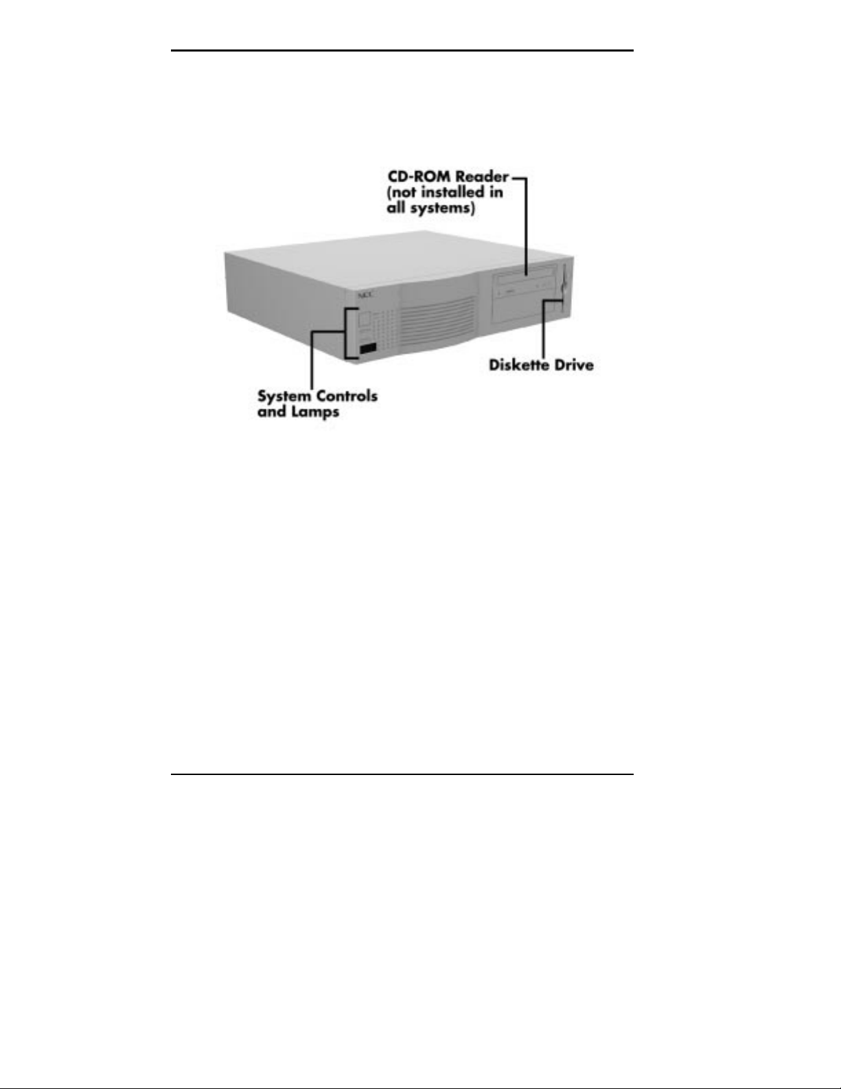
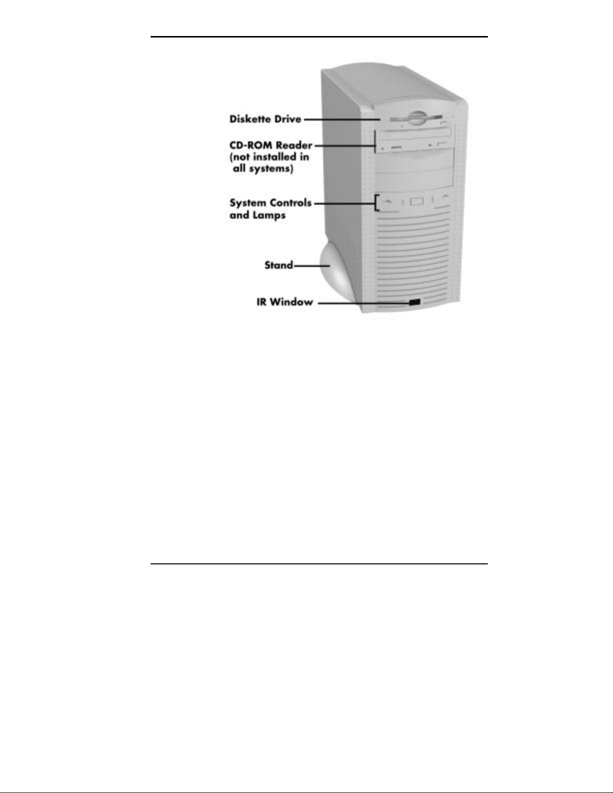
FRONT FEATURES
The following figures show the features on the front of the
system. A brief description follows the figures.
Front features desktop model
1-2 Introducing Your Computer
Front features minitower model
The following figures show the system controls and lamps
called out in the previous figures.
Introducing Your Computer 1-3
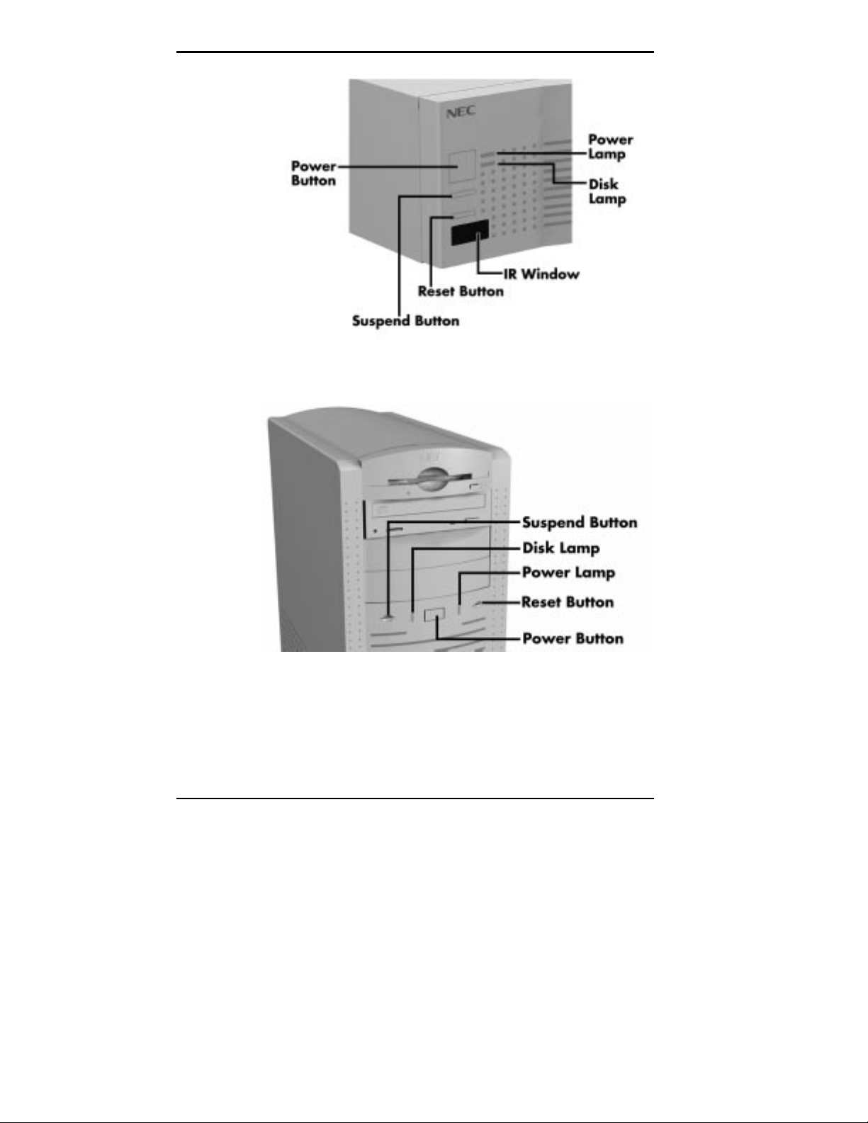
System controls and lamps desktop
1-4 Introducing Your Computer
System controls and lamps minitower

System Controls and Lamps
System controls let you select specific system operations.
Lamps let you know the status of a system operation. Your
computer has the following controls and lamps:
Power button
Press this button to turn on the system power. Press it
again to turn off the power.
Suspend button
Press this button to suspend system operation when you
plan to be away from your computer for a short time.
Press any key or move your mouse to resume system
operation at the point where you stopped it.
An amber system unit power lamp indicates that the
system is in a power-saving mode.
If you have a VESA-compliant monitor, your monitor
also goes into power-saving mode.
Reset button
Use the reset button to restart your computer after it is
powered on. You might need to restart your system if
your system power is on and the computer is not running
properly.
!
Resetti ng your system can resul t i n t he loss of dat a.
Press the reset button only when all other methods
of restarting your computer fail.
CAUTION
Introducing Your Computer 1-5

Power lamp
The power lamp indicates whether system power is on or
off. It also lets you know if the system is operating in a
power-saving mode.
A steady green lamp indicates that the power is on to all
system components. An amber lamp indicates that the
system is in Suspend mode with full-power reduction.
Disk lamp
A lit disk lamp indicates that the hard disk is active. The
green lamp tells you that the hard disk is reading or
writing data.
!
Do not turn off the system unless absolutely
necessary while the disk lamp is lit. To do so can
damage your hard disk or data.
CAUTION
IR Window
The IR (infrared) window is the system’s IR port. The IR
port supports two-way wireless communications. The
interface uses infrared as the transmission medium instead
of a traditional cable.
The IR port lets you transfer files to or from portable
devices such as laptops and personal digital assistant (PDA)
products using application software supporting IrDA data
transfer. Systems running the Windows 95 operating system
come with LapLink
With IrDA software, you can transfer data at speeds of up
to 115 kilobytes per second (Kbps) and at distances up to
3 feet from the IR window.
1-6 Introducing Your Computer
®
software for wireless data transfer.
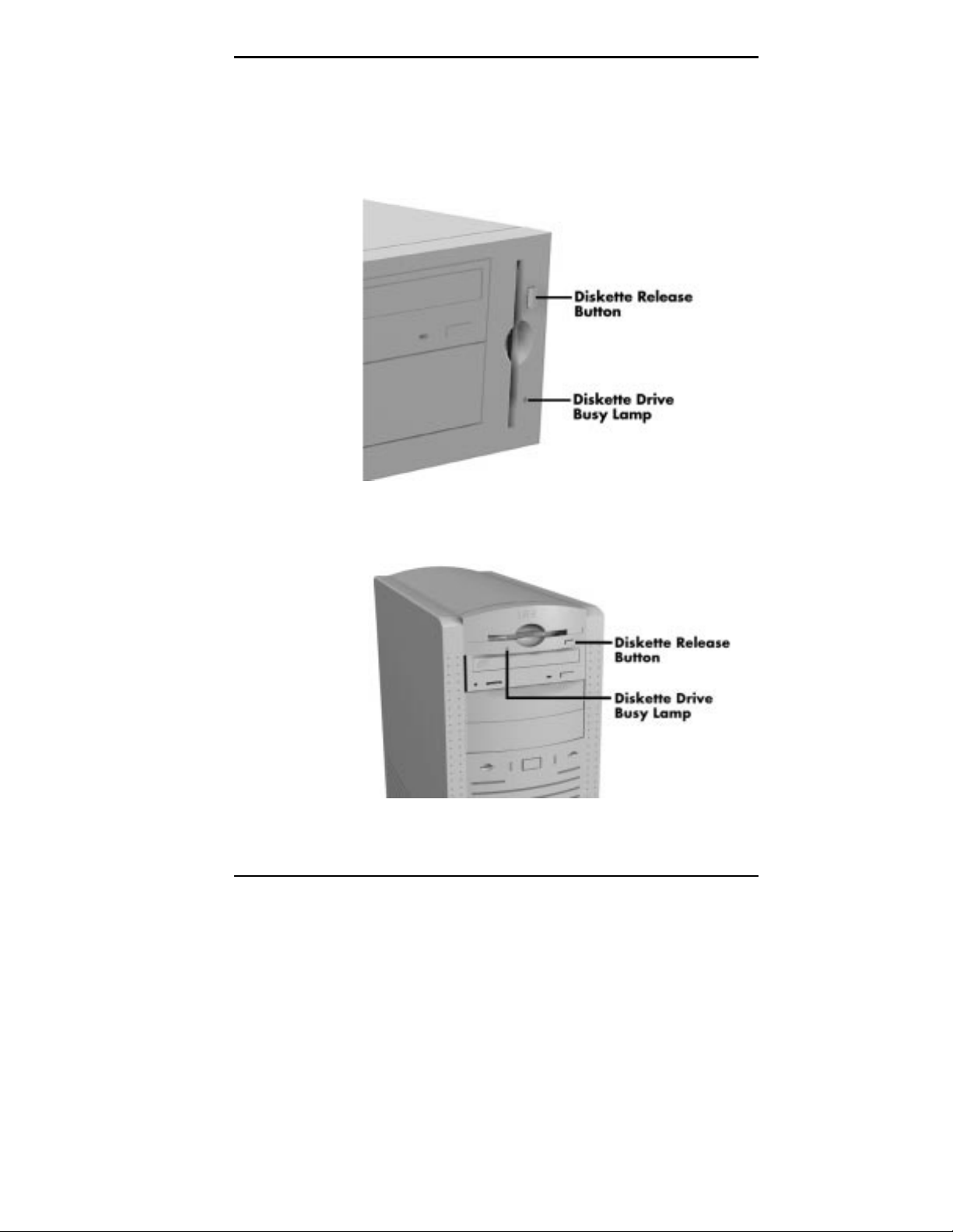
Diskette Drive A
Diskette drive A loads and starts programs from a diskette.
Files can also be copied to and from a diskette. Diskette
drive A may be a bootable drive.
Diskette drive A features desktop
Diskette drive A features minitower
Introducing Your Computer 1-7
Your diskette drive has the following features:
To prev ent damage to y our di skette dr iv e and data,
do not turn off the system or remove a diskette
while the diskette drive busy lamp is lit.
CD-ROM Reader
Your system may come with a 16X or 24X CD-ROM
reader. Use the CD-ROM reader to load and start programs
from a compact disc (CD). If your system has audio, you
can also use the CD-ROM reader to play your audio CDs.
Diskette drive busy lamp
This lamp lights when the diskette drive is reading to or
writing from a diskette.
!
CAUTION
Diskette release button
Press this button to release a diskette from the diskette
drive.
NOTE
You can boot your system f rom the CD- ROM
reader with a bootable CD. To enabl e the system to
boot from the CD-ROM reader, see “Boot Menu” i n
Chapter 4.
The CD-ROM reader operates at different speeds depending
on whether the CD you are using contains data or music.
This allows you to get your data faster and to see smoother
animation and video.
1-8 Introducing Your Computer
NOTE
The CD-ROM reader in your system might
look different from the one shown in the following
figure.
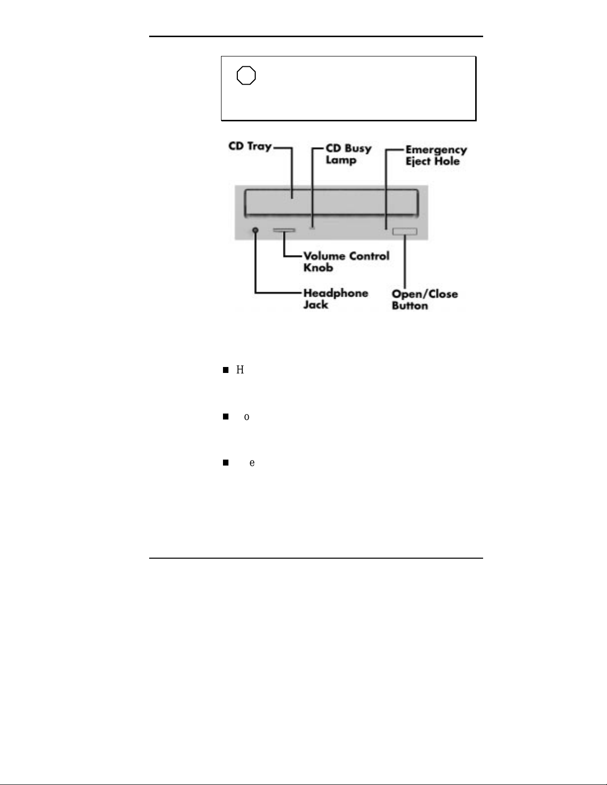
CD-ROM reader features
The CD-ROM reader has the following features:
Headphone jack
Allows the connection of an optional set of headphones
with a stereo mini-jack plug.
Volume control knob
Lets you adjust the volume of an optional set of
headphones.
Open/close button
Opens or closes the reader’s loading tray. Open the
loading tray to insert a CD into or remove a CD from
the reader.
Introducing Your Computer 1-9

Track skip button (not shown)
Advances play to the next track (available in some
models).
Emergency eject hole
Allows the manual ejection of a CD if the eject function
is disabled by software or if a power failure occurs. To
manually eject the CD, insert the end point of a wire
paper clip into the hole and press inward to open the CD
tray.
CD busy lamp
Lights when the reader is retrieving data, music,
graphics, or audio from a CD. Do not eject the CD or
turn off the system unit when the lamp is on.
CD tray
Provides a surface for loading a CD into the reader.
Press the open/close button to open or close the CD tray.
1-10 Introducing Your Computer
PCMCIA Device
If your system has a PCMCIA unit or PC Card Host
you can add PC cards to the system. A PC card is inserted
into a PC card slot much as a diskette is inserted in a
diskette drive, but each type of PC card has a different
function. With one PC card host, you can add a number of
capabilities to your system by getting a variety of PC cards.
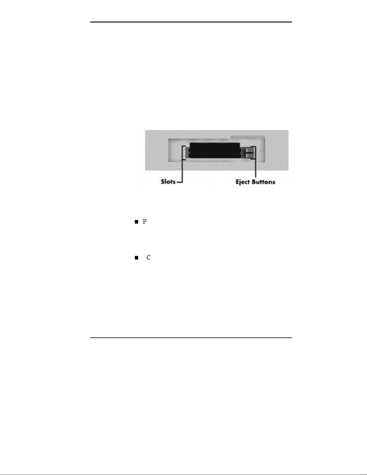
PC card host features are shown in the figure. Feature
descriptions follow the figure.
PCMCIA device features
PC host card slot
The PC host can accommodate two PC cards at the
same time. The system ships with slots that
accommodate Type I and Type II cards.
PC card eject buttons
Each PC host card slot has a card eject button to release
a PC card from the slot.
Introducing Your Computer 1-11

Some of the PC cards currently available are listed below:
memory card
storage device
sound card
SCSI adapter
parallel port interface
serial port interface
token ring LAN adapter card
CD-ROM interface
joystick interface card
cellular phone interface.
Tape Backup Unit
Some models come with a tape backup unit. If your system
has a tape backup unit, you can use it to quickly back up all
or part of your system’s files to a high-capacity tape
cartridge. Backup software helps you tailor the backup
process to protect your files and applications, which are
compressed to conserve space and to speed up the process.
1-12 Introducing Your Computer

Tape backup unit features are shown in the following
figure. Feature descriptions follow the figure.
Tape backup unit features
Tape drive busy lamp
The tape drive busy lamp indicates tape drive activity.
Do not eject the cartridge or turn off the system when
the tape drive busy lamp is on.
Introducing Your Computer 1-13
Zip Drive
Some models come with a Zip drive. Use the Zip drive to
back up work, archive old files, and transport your work.
Up to 100 MB can be stored onto a 3 1/2-inch Zip disk.
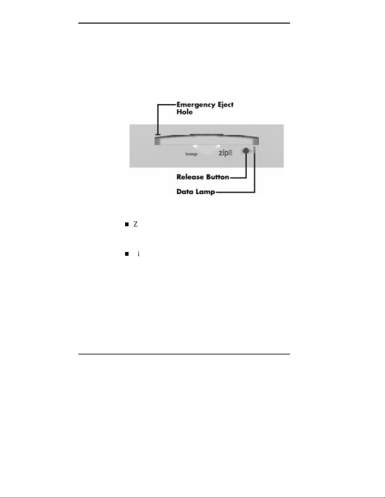
Zip drive features are shown in the following figure.
Feature descriptions follow the figure.
Zip drive features
Zip disk release button
Press the Zip disk release button to release a Zip disk
from the Zip drive.
Zip drive busy lamp
The Zip drive busy lamp indicates Zip drive activity. Do
not eject the disk or turn off the system when the Zip
drive busy lamp is on.
1-14 Introducing Your Computer
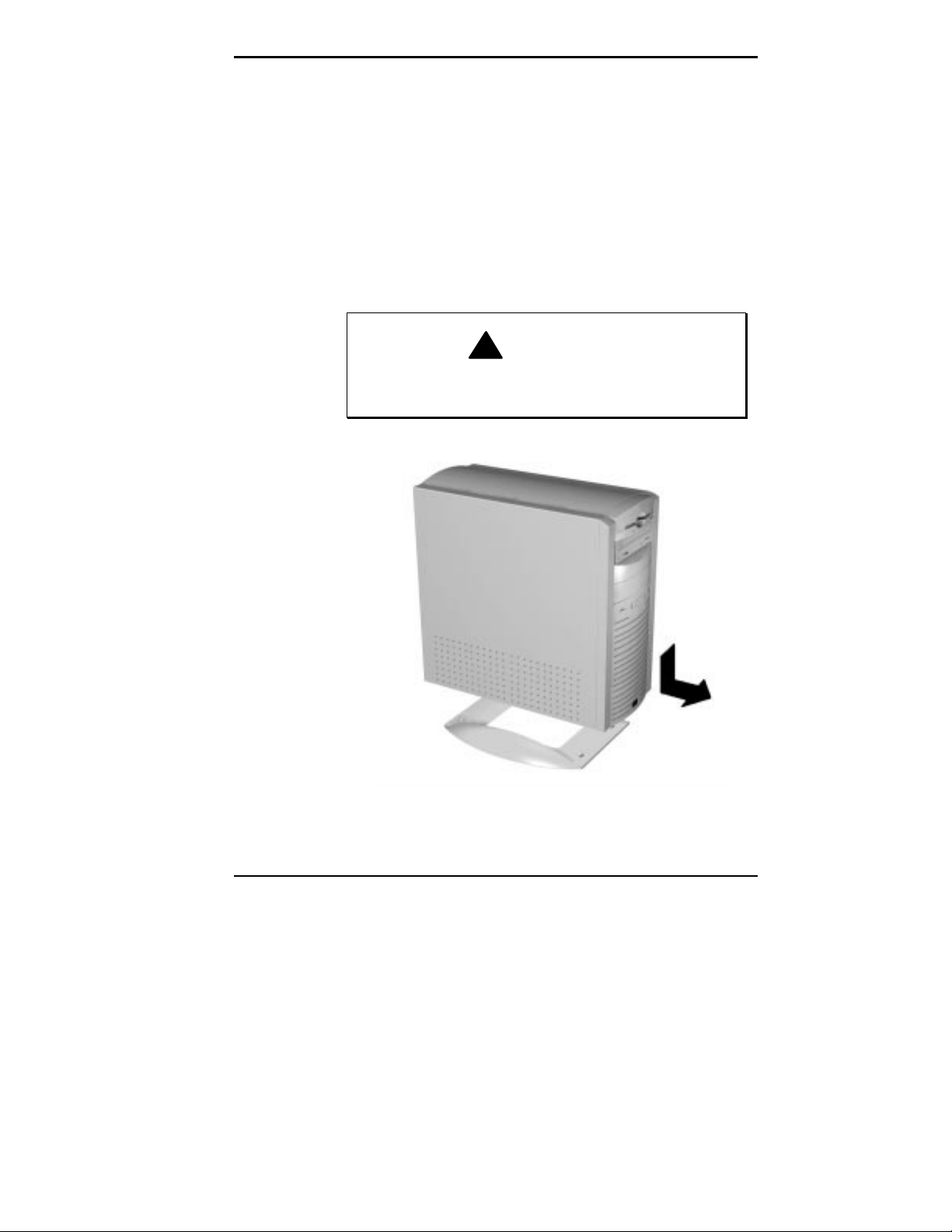
Stand
The minitower system unit sits on a stand to prevent it from
being tipped over. This is a safety feature to prevent
personal injury hazard and equipment damage. Keep the
system unit in the stand except when opening or upgrading
the system.
Place the system unit on the stand so the stand’s tabs go
into the slots in the bottom of the chassis. Slide the system
unit forward to lock the tabs in the slots.
!
Keep the system unit in the stand. The stand is
designed to keep the unit from being tipped over.
WARNING
The minitower stand
Introducing Your Computer 1-15

BACK FEATURES
On the back of your computer, you’ll find external
connectors, power supply features, and expansion board
slots.
The following figure shows back features of the desktop
model.
1-16 Introducing Your Computer
Back features desktop

The following figure shows back features of the minitower
model.
Back features minitower
Introducing Your Computer 1-17

External Connectors
External connectors let you attach peripheral devices, such
as a monitor, keyboard, mouse, and printer to your system.
Your system has the following external connectors:
VGA monitor connector
Attach the signal cable from your monitor to this
connector. Supports an NEC MultiSync
other video graphics array (VGA)-compatible and super
video graphics array (SVGA)-compatible monitors with
a 15-pin connector.
Audio connectors
The following connectors come integrated on multimedia
models:
Microphone in jack
The microphone in jack lets you connect a
microphone for recording audio information in your
data system files.
Line out jack
The line out jack allows you to connect an amplified
output device, such as powered speakers, a stereo
tape recorder, or an external amplifier for audio
output. If you ordered speakers, use this jack to
connect them.
®
monitor or
1-18 Introducing Your Computer

Audio connectors desktop
Audio connectors minitower
Introducing Your Computer 1-19

Printer port
Use this port to connect a parallel printer with a 25-pin
connector to the system.
Serial ports
Attach a serial device with a 9-pin connector to each
serial port. Serial devices include a pointing device,
serial printer, or a modem. (Serial port 2 is disabled by
default; enable COM2 in BIOS to use the port.)
Keyboard port
Attach the keyboard that comes with your computer to
the keyboard port.
The keyboard port supports a PS/2
®
-compatible,
101-key or 104-key keyboard (in the U.S. and Canada)
or a 102-key keyboard (in the United Kingdom and
Germany) with a 6-pin mini DIN connector.
Mouse port
Attach the mouse that comes with your computer to this
port. The mouse port supports a PS/2-compatible
mouse.
Universal Serial Bus ports
The Universal Serial Bus (USB) ports allow you to add
new plug and play serial devices without opening up the
system. You simply plug the devices into the ports. The
USB determines system resources for each peripheral
and assigns them without user intervention. Up to 127
devices can be daisy chained to a single USB port.
Fax/modem ports
Some systems come with a 56 kilobytes per second
(Kbps) fax/modem board. The fax/modem board allows
the connection of a phone line to the computer for fax
and data communications functions.
Dual fax/modem ports let you use a telephone line for
the fax/modem and your telephone.
1-20 Introducing Your Computer

Power Supply
The fax/modem board uses x2 technology. x2 products
are capable of 56 Kbps (52 Kbps in the U.S.). However,
the download speeds you experience may go lower due
to varying line conditions. Uploads from end user to
service provider travel at speeds up to 28.8 Kbps. An
x2-compatible analog phone line and an x2-capable
service provider are required for high-speed downloads.
Go to http://www.usr.com/x2 on the Internet for details.
Network board connectors
If your computer comes with a network board, you can
connect it to an Ethernet network and communicate with
other computers.
Your system has the following power supply features:
Power supply fan
The power supply fan cools system components and
prevents them from overheating. Keep the area near the
fan clear for proper ventilation.
Voltage selector switch
Sets the voltage for your system to 115 volts or
230 volts.
!
Set the switch correctl y f or the v olt age in your ar ea.
Most wall outlets in the United States and Canada
are 115 vol t s. Out let s in Eur ope, Austr ali a, and Asi a
(except Taiwan) are 230 volts. T aiwan uses 115-volt
outlets.
Power socket
Connect your power cable to this socket.
CAUTION
Introducing Your Computer 1-21

Power supply features desktop
1-22 Introducing Your Computer
Power supply features minitower

SPEAKERS
Some systems come with a pair of high-quality stereo
speakers that you can arrange to suit your work
environment. Desktop speakers have 8-watt total output;
minitower systems have 9-watt total output.
An AC adapter comes with the system. Set up the speakers
with the AC adapter. The speakers connect to the line out
jack on the back of the system unit.
The 8-watt speaker set features an on/off button, a power
lamp, and volume, treble, and bass control knobs.
The 9-watt speaker set features an on/off button, a power
lamp, and volume and treble control knobs.
Adjust the speaker volume by using the volume control on
the front of the right speaker or by using the Windows
sound software. To bring up a volume control, double click
the speaker icon on the taskbar (next to the system clock).
Also use the software to balance the sound between the left
and right speakers.
Introducing Your Computer 1-23

2
SYSTEM OPERATION
Using Your Computer
Now that you are familiar with your system, this chapter
provides the information you need to start using your
computer. Some of the information provided includes:
System Operation
Productivity
System Care
Online Documentation
Where to Go From Here.
In this section you will find information on the following:
starting up and shutting down your system
setting the date and time
using system features such as the mouse or CD-ROM
reader
Starting Up
using system protection features.
Press the power button to start up your system. The power
lamp lights green to indicate that the system is on. The NEC
startup screen appears.
Using Your Computer 2-1

At the bottom of this screen, messages like the following
appear:
Press <F2> key to run Setup OR Press ESC to
display POST
NOTE
These messages are part of your system’s
Power-On Self-Test (POST). Your computer is
checking your hardware for any changes since the
last startup. If you want to see the messages
displayed during POST, press ESC. If you want to
go into the Setup Utility, press F2.
One beep indicates that the system has successfully
completed the power-on test. After about 5 seconds,
Windows starts up.
If a problem occurs, a series of beeps may sound. If this
happens repeatedly after powering on, power off the system
and turn to Chapter 8, Solving System Problems. This
chapter provides some helpful hints on obvious system
problems.
NOTE
that system sett ings have changed, run Setup (see
Chapter 4, Using Tools and Utilities).
On PowerMate Enterprise systems loaded with the
Windows NT
when prompted on-screen to do so. The log-on box appears
for entering a password.
2-2 Using Your Computer
If the system displays a message i ndicating
®
4.0 operating system, press
Ctrl-Alt-Del

Shutting Down
Follow these steps to shut down (power off) your computer.
1.
2.
3.
Save your work. See the documentation that comes with
your application.
Exit the application program.
Make sure that the hard disk and diskette drives are not
in use. A lit hard disk lamp or diskette drive busy lamp
indicates that a drive is in use.
!
Wait until a program is finished running before
powering off the system.
Unless absolutely necessary, never power off the
system when the system power lamp is amber or
when either the hard di sk lamp or t he di skette driv e
busy lamp is lit. Information on the hard disk or
diskette might be lost or damaged.
CAUTION
4.
Start
Press
click
on the Windows taskbar, then point to and
Shut Down
. Selecting Shut Down gives you
several choices in the pop-up submenu. Select
down the computer
, and then click
Yes
or press
Shut
to shut down the computer.
5.
Turn off power to your monitor.
6.
Power off the system by pressing the system unit power
button. The system powers off after a 5- to 10-second
delay.
Using Your Computer 2-3
Enter

Setting the Date and Time
To set the system date and time within Windows 95 or
Windows NT 4.0, double click the time display in the lower
right corner of the taskbar. A dialog box appears for setting
the date and time.
Set the date by selecting the current month and year using
the up or down arrows in the dialog box. Set the time by
entering the current hour, minutes, and seconds in
hh:mm:ss, 12-hour format. Select AM or PM using the up
or down arrows.
Using the Keyboard
Your system comes with a PS/2®-compatible, 104-key
keyboard with a 6-pin mini DIN connector. Some systems
come with an ergonomic keyboard to make working at the
computer easier and more comfortable.
Use the keyboard to communicate with your computer. The
keyboard has standard typewriter keys for typing, a keypad
for entering numbers, and special keys you use to move
around the screen, enter commands into your computer, and
perform tasks specific to your application. Keyboard key
functions depend on the operating system or software
application program you use. See your operating system
documentation or software documentation for specific
functions.
In general, your keyboard has four main areas of keys and a
row of status lamps. See the name of the keyboard area
following the figures for a description of it.
2-4 Using Your Computer

Keyboard features
Windows 95 keys
Using Your Computer 2-5

The keyboard has the following features:
Typewriter keys
Use the typewriter keys just as you do on a standard
typewriter.
Windows keys
Press the left or right Windows keys to call up the
Windows Start menu.
Application key
Press the Application key in Windows to bring up a
menu of options specific to the current application.
Function keys
Function keys control functions specific to your
particular software application or operating system. For
example, some programs provide access to help with the
F1 key.
Standard cursor control keys
The standard cursor control keys control the direction of
the cursor. The Num Lock state (Num Lock lamp is on)
does not affect the operation of these keys.
Numeric keypad/cursor control keys
The numeric keypad/cursor control keys work like a
numeric keypad. In Numeric Keypad mode, the Num
Lock lamp is on.
To use the keys to control the direction of the cursor,
press the Num Lock key (Num Lock lamp goes off). To
return to the Numeric Keypad mode, press the Num
Lock key.
To use a keypad cursor key while in Numeric Keypad
mode, press the Shift key and the keypad cursor key.
2-6 Using Your Computer

Using a Mouse
Your mouse has a left button, right button, and a cursor
movement wheel. Use the mouse (shown in the following
figure) to quickly move around on the screen, to select menu
items, and to choose functions specific to your software.
Num Lock lamp
When the Num Lock lamp is on, the keys on the numeric
keypad work like a numeric keypad. When the Num
Lock lamp is off, the keys on the numeric keypad work
as cursor control keys.
Caps Lock lamp
When the Caps Lock lamp is on, all typed letters are
uppercase letters (LIKE THIS). When the lamp is off,
all typed letters are lowercase letters (like this).
Scroll Lock lamp
When the Scroll Lock lamp is on, Scroll Lock key
functions are enabled. When the lamp is off, Scroll Lock
key functions are disabled. Scroll Lock functions depend
upon your application.
In Windows, clicking the right mouse button on the desktop
provides shortcuts to such features as the Properties menu.
Other right mouse button functions depend on the
application program in use. Refer to the application’s
documentation to see what the right mouse button does.
The cursor movement wheel lets you scroll vertically and
horizontally and zoom in to view data on the screen.
Using Your Computer 2-7

You can also drag an object by positioning the cursor over
it and rolling the cursor movement wheel to the new
location.
Mouse
Here are basic ways to use the left mouse button:
Click
Clicking selects an object on your screen. To “click,”
point to the object and press and release the left mouse
button.
Double click
Some actions require a double click to execute them. To
“double click” an object, point to the object and press
and release the left mouse button twice.
2-8 Using Your Computer

Press/Hold
Pressing a mouse button holds an action until you
release a mouse button. For example, pointing to a menu
and pressing the left mouse button holds the menu open
for reading until you release the button.
Drag
Dragging your mouse attaches your pointer to an object
on the screen and allows you to highlight text or move
an object. To drag an object, point to the object, press
the left mouse button, and move the mouse to the new
location.
You can also drag an object by positioning the cursor
over it and rolling the cursor movement wheel to the new
location.
Typical screen objects that you click or double click are
icons, buttons, and menu options.
NOTE
If your mouse pointer disappears, m ove your
mouse in wide circles to bring it back into the
screen.
Use a mouse pad for best results with your mouse. The
mouse pad provides traction for moving the mouse and
results in more sensitivity and control of movement. A
textured pad provides more traction than a smooth pad.
Keep the mouse pad clean.
For more information about your mouse, see The Basics in
the online NEC Help Center and your application
documentation. Also included in the online documentation is
information on cleaning your mouse.
Using Your Computer 2-9

Using Diskettes
Follow these steps to insert a 3 1/2-inch diskette in the
standard diskette drive.
1.
Hold the diskette at its top edge and insert it into the
diskette drive:
in a desktop model, insert the diskette label side
facing left
2-10 Using Your Computer
Inserting a diskette desktop

in a minitower model, insert the diskette label side
facing up.
Inserting a diskette minitower
Insert the diskette all the way into the drive until you
2.
hear a click.
NOTE
must f ormat it bef ore storing inf ormati on on it. See
your operating system documentation for
information about formatting a diskette.
If your diskett e di d not come form atted, you
!
Formatting the hard disk will erase all
preinstalled applications
CAUTION:
Do not fo rmat you r hard di sk.
.
Using Your Computer 2-11

Using CDs
To remove a diskette from the diskette drive, press the
release button on the 3 1/2-inch diskette drive.
!
Do not remove a diskette from the diskette drive
when the diskette drive lamp is lit. To do so can
damage both the data on the diskette and the drive.
Do not turn off the system power while the disket te
is being accessed.
Do not reset the system (except as a last resort)
when the diskette drive is in use.
See the following sections for information about handling,
loading, and removing CDs.
CAUTION
Handling Compact Discs
To protect your CDs from damage, use the following
guidelines when you handle them.
Always pick up the disc by its edges.
Avoid touching the side of the disc that has no printing
or writing on it. This is the data side of the disc.
2-12 Using Your Computer

Handling a CD
Do not write on or apply labels to either side of the disc.
Keep the disc away from direct sunlight or high
temperatures.
Clean fingerprints or dust from the disc by wiping it
with a soft cloth. Gently, brush the cloth from the center
of the disc toward the edge.
Cleaning a CD
Using Your Computer 2-13

Loading a CD
!
Av oid using benzene, pai nt thinner, recor d cleaner,
static repellent, or any other chemical on the disc.
Chemicals and cleaners can damage the disc.
To insert a CD into the CD-ROM reader, follow these
steps:
1.
Press the open/close button. A CD tray slides out from
the reader door.
2.
Remove the CD from its protective case. Hold the CD
by its center hole and outer edges to avoid touching its
surface.
3.
Place the CD, printed side up, into the circular area of
the tray.
4.
Press the open/close button again. The tray
automatically slides into the reader.
CAUTION
Removing a CD
To remove a CD, simply press the open/close button and
remove the CD when the tray slides out. Press the
open/close button again to close the reader door.
You can also eject a CD from Windows. Double click
Computer
CD-ROM reader icon in the My Computer window, and
Eject
click
Your audio software also has a CD eject function.
2-14 Using Your Computer
My
on the Windows desktop, right click the
.

Using PC Cards
Follow these steps to insert a PC card into the PC host.
Holding the PC card at its top edge, insert it, label side
1.
up, into the PC card slot.
Insert the PC card all the way into the drive.
2.
Wait for a beep after inserting the card.
3.
To remove a PC card from the PC card host, press the
release button next to the PC card slot.
Using a Tape Backup Unit
To insert a tape cartridge into the tape backup unit, follow
these steps.
Hold the cartridge with the metal base plate down and
1.
the tape access door facing the drive slot.
Wait until the green drive activity lamp goes off.
2.
Push the cartridge into the drive slot through the flip-up
3.
door. Once the cartridge is fully inserted, the drive’s
locking mechanism holds it in place.
To remove a tape cartridge from the tape backup unit, wait
until the green drive activity lamp goes off, and then pull the
cartridge out of the drive slot.
Using a Zip Drive
Follow these steps to insert a Zip disk in the Zip drive.
Holding the disk at its top edge, insert it, label side up,
1.
into the Zip drive.
Insert the disk all the way into the drive until you hear a
2.
click.
Using Your Computer 2-15

To remove a Zip disk from the Zip drive, press the release
button next to the Zip drive.
Do not remov e a Zip disk f rom the Zip dri ve when
the Zip dri v e lam p is l it. To do so can dam age bot h
the data on the di sk and t he drive. Do not turn of f
the system power whi le the disk is being ac cessed.
Do not reset the system (except as a last resort)
while the drive is in use.
Using the IR Port
In systems running the Windows 95 operating system, the
infrared (IR) port on the front panel and the IrDA interface
allow you to use infrared devices with your computer. Use
the installed Laplink software to communicate with other
computers or use a remote control device. (See the Laplink
documentation for information on using the software.)
!
CAUTION
Before you can use infrared on your system, you must
enable Serial Port B (COM2), and also set Serial Port B
Mode to IrDA through the BIOS Setup Utility.
Enable COM2 for IrDA by following these steps:
1.
Turn on or reboot your system.
2.
Press F2 as soon as you see the message containing this
line:
Press <
You have about five seconds to press
boot continues.
The BIOS Setup Utility window appears.
2-16 Using Your Computer
F2
> for SETUP.
F2
before system

Press the left or right arrow key to highlight the
3.
Advanced
Press the up or down arrow key until
4.
Configuration
menu.
is highlighted. Press
Peripheral
.
Enter
Saving Power
Press the down or up arrow key until
5.
Serial Port B
highlighted.
Press Enter to bring up the Serial Port B submenu.
6.
Press the up or down arrow key to highlight
Press
Press the down or up arrow key until
7.
Mode
Press
8.
.
Enter
is highlighted.
to bring up the Serial Port B Mode
Enter
Enabled
Serial Port B
submenu. Press the up or down arrow key to highlight
. Press
IrDA
Press the left or right arrow key to highlight the
9.
Enter
. Press
Esc
.
Exit
main menu item.
Press the down or up arrow key until the
10.
11.
Changes
Press
Enter
submenu item is highlighted.
. The system restarts.
Exit Saving
You can enter a power-saving state Suspend mode
by pressing the suspend button on the front of your unit.
Pressing the suspend button is a convenient way of
conserving energy when you are going to be away from
your system for a short period of time.
is
.
Using Your Computer 2-17

!
Take care to avoid pressing the power or reset
button instead of the suspend button. Accidentally
pressing the power or reset buttons can resul t i n t he
loss of data.
In the desktop model, the suspend button is
below the power button and above the reset
button.
In the minit ower model, t he suspend button is to
the left of the power button and the reset button.
CAUTION
Suspend mode provides the greatest power savings by
putting the system in a maximum power shutdown. When
the system goes into Suspend mode, it saves data and
system status and then shuts off power to all possible
components. Suspend mode lets you save power without
first saving your work.
An amber power lamp indicates your system is in a powersaving mode. Press a key or move your mouse to resume
system operation where you left off.
Protecting Your Work
Your system’s security features provide protection against
unauthorized access to your system and data:
The system BIOS Setup utility program (see “The Setup
Utility” in Chapter 4) includes a feature that enables you
to set up a user and administrator password.
Windows contains network security features. To learn
more about them, refer to your Windows documentation
or consult your system administrator.
2-18 Using Your Computer

PRODUCTIVITY
The following sections explain how to use your system to
maximize your productivity.
Saving Your Work
Save your work often! The time you take to periodically
save your data file as you work can save you time in the
end! Prevent losing a whole day’s work or more when the
unexpected happens, such as losing power due to a power
outage.
Some applications have an automatic save feature. When
the feature is enabled, the application saves your work for
you every time an interval of your choosing passes while the
file is open. For example, you might want to save your
work every 10 minutes. Using this feature reduces the
amount of information you could lose if there’s a power
outage or a system problem.
In some Windows programs, you can select automatic save
as an option from the
creating a new file, you’ll first need to specify a name for
your file and the drive and directory to store it in.
File
and
Save As
menus. If you are
Always save your work before you exit an application. See
the application’s documentation for available save options.
Backing Up Your Work
Back up your work on a regular basis! Backup procedures
are important for the efficient and effective use of your
computer. Protect your program and data files with regular
backup procedures.
Make backup copies of your program and data files that are
on diskette and on the hard disk.
Using Your Computer 2-19

The standard practice for diskette backup is to copy each
diskette, store the original in a safe place, and use the copy
as your working diskette. See your operating system
documentation for information about copying diskettes.
NOTE
system has a built -in backup f eatur e incl uded i n the
LANDesk® Client Manager software that comes
preloaded on your com put er. T hi s f eat ure aler ts y ou
to possible system probl ems and lets you back up
your files to a tape drive or a network drive. For
further inf orm at ion, see “LANDesk Cli ent Manger” i n
Chapter 4.
Printing a Document
Before you can print out a document, you must
connect your computer to a printer or to a network
connected to a printer
For additional protection of your files, the
set up the printer.
If you have not connected a printer, see “Connecting a
Parallel Printer” in Chapter 5.
If you did not choose a printer when you initially set up
your computer, you’ll need to do that before you can print
(see your Windows documentation). If you are using a nonWindows program, you need to set up a printer driver for
that program. See your printer documentation for printer
setup information.
2-20 Using Your Computer

Once your program is set up to work with your printer,
printing a file within a Windows application is easy:
Turn on your printer power if necessary.
1.
Be sure you have paper in your printer. See your printer
2.
documentation to load paper.
Check that the printer is “online” or “selected.” See your
3.
printer documentation for information about choosing
the online mode.
4.
Select
from the File menu of your Windows
Print
application. A Print dialog box appears.
Select how many print copies you want and the range of
5.
pages. To print one copy of all the pages, simply click
.
OK
SYSTEM CARE
Your system is a durable, dependable computer built for
heavy use. With protective measures and proper care, you
can prevent problems and promote the successful operation
and long life span of your computer.
Protecting Your System from Damage
There are several ways that you can protect your system
from possible damage. NECCSD strongly recommends the
following protective measures:
The minitower system unit sits on a stand to prevent it
from being tipped over. This is a safety feature to
prevent personal injury hazard and equipment damage.
Keep the system unit in the stand.
Connect a surge suppressor between your computer and
a grounded wall outlet. A surge suppressor protects your
system from sudden transient increases and decreases in
electrical power.
Using Your Computer 2-21

Be sure to connect all peripherals, such as your monitor
and printer, to the surge protector. The surge protector
should be the only device that you plug into the wall
outlet.
Avoid repeated power-on cycles. These subject the
system components to temperature variations and stress.
Disconnect your system from telephone and power lines
when an electrical storm threatens. If you have a
fax/modem, lightning can travel in on the phone line and
damage both the fax/modem and the system unit.
Lightening can also travel in on power lines and damage
your monitor and system unit.
Be sure that system power is off before you connect or
disconnect a cable. Never make cable changes when the
system power is on. To do so could damage your system
and its peripherals.
Use appropriate virus detection software regularly to
protect your system from computer viruses.
If you plan to use software programs other than
NECCSD-supplied software, NECCSD strongly
recommends that you take the necessary steps, such as
virus checks, to protect your system.
Use Setup options to set up an automatic reminder to
run a virus check (see “Power Menu” in Chapter 4).
Place your computer away from direct sunlight and
extreme hot and cold temperatures.
The recommended operating environment is from 50°F
to 95°F (10°C to 35°C).
The recommended non-operating environment (shipping
or storage) is from 14°F to 158°F (-10°C to 70°C).
After turning off power, wait about five seconds for the
hard disk to spin down before you power on again.
2-22 Using Your Computer

Be sure that nothing is placed on top of your system
power cables.
Prevent dust from entering your system by covering it
when it is not in use.
Keeping Your System in Good Condition
Maintain the condition of your system by periodically using
the following general procedures.
!
For safety, power off and unplug your system,
monitor, and any external devices before cleaning
them.
Clean the outside of the computer with a soft clean cloth.
You can remove stubborn stains with a cloth slightly
dampened with a mild detergent. Never use a strong
cleaner or solvent on any part of the system.
WARNING
Keep food and liquids away from your computer.
Periodically clean the keyboard with a vacuum cleaner
brush attachment. Do not use any liquid cleaners on the
keyboard as they can damage the keyboard.
If an object, such as a paper clip, falls into the keyboard,
turn the keyboard over and gently shake it.
Clean the monitor screen with a monitor glass cleaner
and wipe it with a clean, lint-free cloth. You may use
wet/dry cleaning pads manufactured for monitor screens.
Using Your Computer 2-23

Cleaning Your Mouse
Under normal conditions, your mouse has a self-cleaning
mechanism that prevents a buildup of dust or lint around the
mouse ball and tracking mechanism. Periodically, however,
you might need to clean the mouse ball.
Use these steps to clean your mouse:
Power off your computer and any peripherals attached
1.
to it.
Invert the mouse. Locate the mouse ball cover.
2.
Rotate the ball cover counterclockwise and remove the
3.
cover.
Turn the mouse over so that the cover and ball fall into
4.
your palm.
Clean the mouse as follows.
5.
2-24 Using Your Computer
Mouse ball cover
Use tap water, or tap water and a mild detergent, to
clean the mouse ball.
Use a clean, lint-free cloth to dry the ball.
Blow into the mouse socket to remove remaining dust
or lint.

Gently put the ball back into the mouse.
6.
Fit the ball cover back into the mouse and turn the cover
7.
clockwise until it locks in place.
Moving or Shipping Your System
Use these steps to prepare your system for moving or
shipping:
Back up your hard disk files onto diskettes, Zip disks,
1.
or tape cartridges.
Be sure to take precautions for storing and transporting
diskettes or cartridges so that they are not exposed to
magnetic fields or electrical impulses.
Remove any diskette from the diskette drive. If you have
2.
a CD in the CD-ROM reader, remove the CD.
Turn off the system unit and any external options
3.
connected to it.
Unplug the system unit power cable from the wall outlet
4.
or surge suppressor, then from the unit itself.
Unplug any external options from the wall outlets or
5.
surge suppressor, then disconnect them from the system
unit.
For minitower models, remove the stand.
6.
Pack the system components in the original shipping
7.
materials and cartons. If these are not available, be sure
to use adequate packing materials to protect the
components.
To set up your system, follow the steps on the PowerMate
Enterprise Quick Setup poster that comes with your
computer.
Using Your Computer 2-25

ONLINE DOCUMENTATION
Your system comes with documentation conveniently
available at your fingertips. Information about your system
is available right from the Windows desktop.
NOTE
To optimize the graphics in the online NEC
Help Center, configure the monitor for high color.
The graphics in the NEC Help Center are enhanced when
viewed with high color. To configure the system for high
color, use the following steps:
Close any applications that are open.
1.
Right click on the Windows desktop. Click
2.
The Display Properties window opens.
Click the
3.
In the
4.
(16 bit)
Click OK. Restart your system.
5.
To access the system documentation, double click the
Online Docs shortcut icon on your Windows desktop to
open the NEC Help Center. A welcome screen appears with
the information you need to use the online documentation.
2-26 Using Your Computer
Settings
Color Palette
.
tab.
field, highlight
Properties
High Color
.

The NEC Help Center is a comprehensive source of
information about your system. To help you find the
information you need, the documentation is organized by
topic and the following modules:
System Tour
The Basics
Advanced Topics
Question & Answers
System Upgrades
Service & Support.
Other online documents include the Healthy Environment
help file that complements the “How Does Your Workplace
Measure Up?” brochure.
Most of your application programs provide extensive online
help at the touch of a button (usually the Help button).
Some programs provide separate online user’s guides for
specific applications.
Windows provides extensive online help and “wizards” to
guide you through procedures.
Using Your Computer 2-27

WHERE TO GO FROM HERE
Once you have your system up and running, we suggest that
you do the following:
See “Setting Up a Healthy Work Environment” either in
Appendix A of this User’s Guide or in the online
Healthy Environment help file.
Take the System Tour in your online NEC Help Center.
See The Basics in your online NEC Help Center.
Install any applications. See the documentation that
comes with the application.
See the following quick reference chart to find information
about some of the things you might want to do.
Quick Reference to Information About Your Computer
WHAT YOU WANT TO FIND WHERE TO FIND IT
Basic information about my
computer
Setting a password “Setting a Password” in Advanced Topics in
Loading a CD “Loading a CD” in The Basics (NEC Help
Playing a music CD
(multimedia systems)
Using the suspend button “Saving Power” and “Managing Power” in The
Adding options System Upgrades in your online NEC Help
2-28 Using Your Computer
The Basics in your online NEC Help Center
your online NEC Help Center and “Security
Menu” in Chapter 4 of this guide
Center)
Questions & Answers in your online NEC
Help Center
Basics (NEC Help Center)
and “Installing Options” in Chapter 5
Center
of this guide

Quick Reference to Information About Your Computer
WHAT YOU WANT TO FIND WHERE TO FIND IT
Understanding power
management
Access to the World Wide
Web
Transferring files from my
laptop to my computer via
the IR window
Protecting my system from
viruses
Video drivers “Video Drivers” in Advanced Topics (NEC
Using Desktop Management
Interface
Using support services “24-Hour Information Services” in Service &
Taking care of my system “Taking Care of Your System” in The Basics
Troubleshooting tips Chapter 8 of this guide
“Saving Power” and “Managing Power” in The
Basics (NEC Help Center)
“Getting Help” in Service & Support (NEC
Help Center)
LapLink online help and “A Look at the Front”
in The Basics (NEC Help Center)
“Your Software” in System Tour (NEC Help
Center)
Help Center)
“LANDesk Client Manager” in Chapter 4 of
this guide
Support (NEC Help Center
of this guide
(NEC Help Center)
)
, and Chapter 7
Using Your Computer 2-29

Reviewing System
3
Features
Depending on your model, your computer has a 166-MHz
®
or 200-MHz Pentium
166-MHz, 200-MHz, or 233-MHz MMX microprocessor
and enhanced cache memory. The MMX processor
technology boosts audio, video, and 3D graphics
performance.
All PowerMate Enterprise systems come with the following
factory-installed features:
3 1/2-inch, 1.44-megabyte (MB) diskette drive
16 MB (minimum) of Synchronous Dynamic Random
Access Memory (SDRAM)
S3 Trio 64 ViRGE/GX 3D video adapter.
The rest is up to you! Your system supports many optional
hardware features available from NECCSD, including
memory expansion modules, audio and video components,
and a CD-ROM reader. A fax/modem board, video board,
and several network boards are also offered. Systems are
also available with a SCSI adapter board, SCSI hard disk
drive, Zip drive, PCMCIA device, or a tape backup unit.
microprocessor, or a Pentium
In addition, the system supports a user-selectable IDE hard
disk that is compatible with the Ultra DMA/33 standard for
high-speed data transfers. (IDE devices that are not Ultra
DMA/33-compatible are also supported.)
Reviewing System Features 3-1

Depending on your model, your system might ship with the
following software installed on your hard disk:
Microsoft® Windows NT® 4.0 or Windows® 95
Healthy Environment Help file
S3 3D ViRGE/GX or Diamond Stealth Pro 2000 video
drivers
Active Movie video drivers for Windows 95 and
Windows NT 4.0
Yamaha or Creative Labs CT4335 audio drivers
US Robotics 56-KB Akita II modem drivers
Microsoft Internet Explorer for Windows NT 4.0 or
Windows 95
McAfee® VirusScan™
LANDesk® Client Manager with NEC Security and
Cheyenne Backup
Microsoft Windows NT 4.0 or Windows 95 Bus Master
IDE drivers
CD-ROM drivers
LapLink™ (Windows 95 systems only)
FirstAid Deluxe™ 97 (Windows 95 systems only)
IntelliMouse mouse drivers for Windows NT 4.0 or
Windows 95.
A diskette containing QA Plus™ Pro software and CDs
containing copies of your operating system and drivers are
included in the shipping carton.
3-2 Reviewing System Features

SYSTEM CHASSIS
The chassis provides an enclosure for the system board,
power supply, expansion slots, and storage device slots.
Desktop Chassis
The desktop chassis has three expansion slots and four
storage device slots. The expansion slots include one
8-/16-bit ISA slot (1/2-length), one shared PCI/ISA slot,
and one 32-bit PCI slot.
The four storage device slots accommodate up to three
accessible devices and one internal hard disk drive. The
accessible device slots support the standard one-inch high,
3 1/2-inch 1.44-MB diskette drive and two 1.6-inch high,
5 1/4-inch storage devices. The internal device slot supports
a single one-inch high, 3 1/2-inch hard disk drive.
The following figure shows the locations of the storage
devices in the desktop chassis for a typical configuration.
Desktop chassis features
Reviewing System Features 3-3

Minitower Chassis
The minitower chassis has five expansion slots and six
storage device slots. The expansion slots include one
8-/16-bit ISA slot, one shared PCI/ISA slot, and three
16-bit PCI slots. The shared PCI/ISA slot does not support
PCI Bus Master cards.
The six storage device slots accommodate up to four
accessible devices and two internal hard disk drives. The
accessible device slots support the standard one-inch high,
3 1/2-inch diskette drive and three 1.6-inch high, 5 1/4-inch
storage devices. The internal device slots support two oneinch high, 3 1/2-inch hard disk drives.
The following figure shows the locations of the storage
devices in the minitower chassis for a typical configuration.
3-4 Reviewing System Features
Minitower chassis features

SYSTEM BOARD COMPONENTS
Your PowerMate Enterprise Series system board has the
following components.
Processor
Depending on your model, processing for your system is
provided by the 166-MHz, 200-MHz, or 233-MHz Intel
Pentium microprocessor. Some processors include MMX
technology for enhanced multimedia operation.
Cache
The board integrates a 16-KB internal cache (32 KB in
MMX systems) and a 512-KB secondary cache and cache
controller to improve system performance.
Math Coprocessor
An integrated math coprocessor increases the speed of
floating point operations.
System Memory
The system comes in configurations starting with a
minimum of 16 MB of system memory. Two sockets on the
system board support up to 256 MB of high-speed memory
using industry-standard, gold-plated, 168-pin dual in-line
memory modules (DIMM).
NOTE
You can install approved vendor list (AVL),
10-ns or 12-ns, Synchronous Dynamic Random
Access Memory (SDRAM) DIMMs into the m emory
sockets.
Reviewing System Features 3-5

Memory can be installed in one socket or both. The memory
type, size, and speed can vary between sockets. The system
automatically detects the memory; no jumper settings are
required. The DIMMs can be either single- or double-sided.
The minimum allowable memory size for the system is
8 MB, and the maximum is 256 MB.
See Chapter 5 for DIMM option installation procedures.
The following table describes supported DIMM modules.
Supported DIMMs
DIMM TYPE CONFIGURATION TECHNOLOGY
8 MB CAS Latency 2 SDRAM 1 M x 64 16 Mbit
16 MB CAS Latency 2 SDRAM 2 M x 64 16 Mbit
32 MB CAS Latency 2 SDRAM 4 M x 64 16 Mbit
64 MB* CAS Latency 2 SDRAM 8 M x 64 16 Mbit
128 MB* CAS Latency 2 SDRAM 16 M x 64 64 Mbit
*64-MB and 128-MB modules are supported when available.
Interrupt Controller
The interrupt controller operates as an interrupt manager
for the entire system environment. The controller accepts
requests from peripherals, issues interrupt requests to the
processor, resolves interrupt priorities, and provides vectors
for the processor to determine which interrupt routine to
execute. The interrupt controller has priority assignment
modes that can be reconfigured at any time during system
operations.
3-6 Reviewing System Features

The interrupt levels are described in the following table.
Interrupt-level assignments 0 through 15 are in order of
decreasing priority. See “The Setup Utility” in Chapter 4
for information on changing the interrupts using the Setup
Utility.
Interrupt Level Assignments
INTERRUPT PRIORITY INTERRUPT DEVICE
IRQ00 Counter/Timer
IRQ01 Keyboard
IRQ02 Cascade (INT output from slave)
IRQ03 COM2* and COM4
IRQ04 COM1 and COM3
IRQ05 Audio (if present)
IRQ06 Diskette Drive Controller
IRQ07 Parallel Port 1
IRQ08 Real-time clock
IRQ09 S3 Video and USB
IRQ10 Available
IRQ11 Network Card if present
IRQ12 PS/2 mouse
IRQ13 Coprocessor
IRQ14 Primary IDE
IRQ15 Secondary IDE
* Disabled by default.
Reviewing System Features 3-7

PCI Local Bus
The 32-bit industry-standard PCI bus is a highly integrated
input/output (I/O) interface that offers the highest
performance local bus available for the Pentium-based
processor. The PCI bus supports burst modes that send
large chunks of data across the bus, allowing fast displays
of high-resolution images.
The high-bandwidth PCI local bus eliminates data
bottlenecks found in traditional systems, maintains
maximum performance at high clock speeds, and provides a
clear upgrade path to future technologies.
The PCI bus contains the embedded PCI local bus IDE
interface and supports the video controller.
Flash ROM
The NEC Flash ROM allows fast, economical BIOS
upgrades. NEC Flash ROMs are reprogrammable system
and video EPROMs.
With NEC Flash ROM, a ROM BIOS change:
is fast and easily done using a Flash utility
eliminates the expensive replacement of ROM BIOS
chips, and reduces system maintenance costs
reduces inadvertent system board damage that can take
place when replacing ROMs
facilitates adopting new technology while maintaining
corporate standards
gives network administrators company-wide control of
BIOS revisions.
Information on how to use the Flash utility is provided in
Chapter 4, “Using Tools and Utilities.”
3-8 Reviewing System Features

Graphics Features
Your system features a PCI local bus motion video
playback controller and graphics accelerator (S3 Trio 64
ViRGE/GX) on a single chip on the system board.
NOTE
The following sections describe the features
of the S3 Trio 64 ViRGE/GX graphics chip on the
system board. If you install your own graphics
board, its features may be different.
Motion Video Controller
The motion video controller is supported on multimedia
configurations. The video controller integrates a Windows
graphical user interface (GUI) engine and motion video
playback hardware. This means you can view 3D graphics
and movies on your computer. Support includes:
MPEG-1 or MPEG-2
Video for Windows
Active Movie (Windows 95 only).
MPEG is a compression/decompression standard developed
by a professional video group called the Motion Picture
Experts Group. MPEG produces full-screen, 30-framesper-second (fps), broadcast-quality digital video.
Graphics Accelerator
The graphics accelerator is designed for graphics-intensive
operations, 3D effects, texture mapping, text and color pixel
amplification, and scrolling. The graphics accelerator
provides 64-bit, ultra-high performance for demanding True
Color, High Color, and pseudocolor GUI and computeraided design (CAD) applications.
Reviewing System Features 3-9

The accelerator minimizes bus traffic by off-loading the
tasks normally performed by the processor. The dedicated
bit-block transfer (BitBLT) engine maximizes performance
by speeding the movement of large blocks of image data in
video memory.
Video Support
Your system has 2 MB of Synchronous Graphics RAM
(SGRAM) on the system board.
The system supports the following resolutions, colors, and
refresh rates for systems with 2 MB of video memory.
Supported Refresh Rates
REFRESH RATE (HZ)
RESOLUTION
640 x 480 60 60, 70, 72, 75,85 60, 72, 75, 85 60, 72, 75, 85
4-BIT COLOR
(16 COLORS)
8-BIT COLOR
(256 COLORS)
15-/16-BIT
COLOR
(32K/64K
COLORS)
24-BIT
COLOR
(16M
COLORS)
800 x 600 56, 60, 72, 75,85 56, 60, 72, 75,85 56, 60, 72, 75,85 56, 60, 72,
1024 x 768 43 (IL), 60,
1152 x 864 Not supported 60 Not supported Not
1280 x 1024 43 (IL), 60,
1600 x 1200 Not supported 48.5 (IL), 60 Not supported Not
IL = Interlaced
K = thousand
M = million
3-10 Reviewing System Features
70, 75, 85
75, 80
43 (IL), 60, 70,
75, 85
43 (IL), 60,
75, 85
43 (IL), 60, 70,
75, 85
Not supported Not
75, 85
Not
supported
supported
supported
supported

High-Speed Communication Ports
Your system features an enhanced parallel port and two
buffered high-speed serial ports. (One serial port, COM1, is
enabled by default.)
The enhanced parallel port supports Enhanced Capabilities
Port (ECP) and Enhanced Parallel Port (EPP) modes for
devices that require ECP or EPP protocols. These protocols
allow high-speed bidirectional transfer over a parallel port
and increase parallel port functionality by supporting more
devices.
The buffered high-speed serial ports support transfer rates
up to 115.2 kilobytes (KB) per second. These ports allow
the installation of high-speed serial devices for faster data
transfer rates.
The combination of the enhanced parallel port and buffered
serial ports ensure optimum performance for future
peripheral devices and operating systems.
Dual IDE Ports
The riser board in your system provides two internal IDE
ports:
a primary IDE port
a secondary IDE port.
Each port supports two devices for a total of four IDE
devices. For system configuration flexibility, your computer
allows the connection of an IDE device without the addition
of a controller.
Either IDE port supports the Ultra DMA/33 standard for
33.3 MB per second, 32-bit wide data transfers on the highperformance PCI local bus, as well as an enhanced IDE
interface that supports up to 16 MB per second, 32-bit wide
data transfers on the PCI bus.
Reviewing System Features 3-11

USB Ports
The Universal Serial Bus (USB) ports allow you to add new
serial devices without opening up the system — simply plug
them into the ports. The USB determines system resources
for each peripheral and assigns them without user
intervention. Up to 127 devices can be daisy chained to a
single USB port.
Sound System
The Yamaha sound system installed on the system board in
multimedia models provides compatibility with Sound
Blaster Pro™, Sound Blaster™ 2.0, Ad Lib™, MPU-401,
and Microsoft® Windows Sound System™ for PC sound
applications.
NOTE
In the desktop model, one Ultra DMA/33
device is supported on each IDE channel. If an
additional IDE device is added to an IDE channel,
neither dev ice can use Ultra DMA/ 33 mode due t o
the length of cable required.
For detailed sound specifications, see the “System
Specifications” in Appendix B.
Plug and Play Support
Your computer comes with a Plug and Play BIOS which
supports Plug and Play technology. Plug and Play
eliminates complicated setup procedures for installing Plug
and Play expansion boards.
3-12 Reviewing System Features

With Plug and Play technology, you add a Plug and Play
expansion board simply by powering off the system,
installing the board, and powering on the system. There are
no jumpers to set and no system resource conflicts to
resolve. Plug and Play automatically configures the board
for your system.
Your system also supports non-Plug and Play boards.
Power Saving Feature
A suspend button lets you quickly put the system into a full
power reduction mode of operation. This is a convenient
way to save power when you need to be away from your
computer for a short period of time. Press a key or move the
mouse and your system quickly returns to full power and to
where you left off.
Reviewing System Features 3-13

Using Tools and
4
THE BIOS SETUP UTILITY
Utilities
This chapter provides information about your computer’s
software tools and utility programs. These include:
BIOS Setup utility
Flash utility
LANDesk® Client Manager
NEC Select Install CD.
The BIOS Setup utility program is used to configure the
main components of your computer.
NOTE
Your system ships from the factory with the
correct system parameters for your configuration.
Unless you add optional har dware, you do not need
to run the BIOS Setup utility to operate your system.
However, you might wish to run the Setup utility to
set features that customize your system, such as
security features.
Using Tools and Utilities 4-1

System configuration information is stored in nonvolatile
memory. A nonvolatile memory device retains its data when
system power is turned off. Nonvolatile memory in your
system is stored in a complementary metal-oxide
semiconductor (CMOS) chip backed up by a battery on the
system board. The battery supplies continuous power to
CMOS memory and maintains configuration information
when system power is off (see “Replacing the Battery ” in
Chapter 8).
NOTE
NECCSD recommends that you print out or
write down your current Set up param eter s and store
the information in a safe place. This will enable you
to restore your system to the current param eters if
you ever need to replace the battery.
When to Use BIOS Setup
The Setup utility lets you view and set system parameters.
Use the Setup utility program to:
set the time and date.
update or check system parameters when you add or
remove expansion options.
change or set power management features.
correct a hardware discrepancy when the Power-On
Self-Test (POST) displays an error message and
prompts you to run Setup.
4-2 Using Tools and Utilities

check the installation of optional memory by comparing
the amount of memory installed with the amount of
memory displayed by Setup.
change certain system operating parameters, such as
boot device sequence and keyboard parameters.
configure system connections for peripherals such as
your diskette drive, hard disks, and devices connected to
the printer port and serial ports.
customize your system with security features such as
passwords, diskette drive restriction, virus check
reminder, and system backup reminder.
set system parameters in the event that you need to
replace the complementary metal oxide semiconductor
(CMOS) battery.
How to Start BIOS Setup
To start the Setup utility, follow these steps:
Turn on or reboot the system.
1.
To start the memory test before the system boots up,
2.
press
after POST.
F2
There is about five seconds in which to press
the system boot continues.
After F2 is pressed, the screen displays the message,
“Entering Setup.”
Using Tools and Utilities 4-3
F2
before

Setup’s Main Menu appears and looks similar to the
3.
following screen.
4-4 Using Tools and Utilities
Setup Main Menu

How to Use BIOS Setup
Use the keys shown on the bottom of the Setup menu to
make your selections or exit the current menu. The
following table describes the navigation keys.
Navigation Keys
Key
F1 Provides help for the parameter field
Esc Exits the menu
Enter Executes Command or brings up a
↓ or ↑ arrow keys
← or → arrow
keys
F9 Loads the Default Configuration values
F10 Save and Exit
Function
being displayed.
submenu
Moves cursor up and down
Selects next menu
for this menu
Menu items preceded by > contain a submenu of selectable
fields for setting system parameters. To display a submenu,
use the arrow keys to move the cursor to the submenu you
want. Then press
Enter
.
Using Tools and Utilities 4-5

Main Menu
Choose the Main Menu by selecting Main Menu in the
legend bar. Other Main Menu options are available by
selecting submenus.
NOTE
See “How to Start BI OS Setup” f or a l ook at
a typical Main Menu screen.
Use the arrow keys to select one of the following Main
Menu options and press
with grayed-out text are not available. Explanations of each
menu item follow.
Displayed Information
The following information is displayed in the Main menu.
These fields are read-only and cannot be changed:
Processor type
to select a submenu. Items
Enter
Processor speed
Cache RAM
Total Memory
BIOS version.
Language
Selects the current language used by the BIOS. Use this
field to select English (the default) or French.
4-6 Using Tools and Utilities

System Time/Date
Use this menu to set the current time and date. The clock
keeps time even after the system power is turned off.
To set the time, enter the current hour, minute, and seconds
in hh:mm:ss, 24-hour format. Press
between fields. For example, type
1:30 P.M.
To set the date, enter the current month, day, and year in
mm/dd/yyyy format. Press
fields. For example, type
30, 1997.
Floppy Options
This field is used to select the type of diskette drive in your
system. Diskette A is set to “1.44/1.25 MB 3 1/2” by
default, and Diskette B is set to “Disabled.” Unless you are
changing your hardware, you do not need to change the
diskette drive (floppy) A or B settings.
If you add an optional diskette drive to your system, select
“Floppy B” and the select parameter value corresponding to
the drive being added.
or
Tab
13<tab>30<tab>00
or
Tab
07<tab>30<tab>1997
Enter
Enter
to move between
to move
for
for July
The Floppy Write Protect field allows you to configure the
floppy diskette drive(s) so that no information can be
written to a diskette. Set the field to “Enabled” to write
protect diskettes.
Primary and Secondary IDE
The Primary and Secondary IDE Master and Slave settings
control the following types of devices:
hard disk drives
CD-ROM readers
Zip drives
tape backup units.
Using Tools and Utilities 4-7

Your computer comes with the hard disk drive (drive C:)
configured as the “Primary IDE Master.” The system can
support up to four physical IDE drives (two on each
PCI/IDE connector). Choices include:
Primary Master
Primary Slave
Secondary Master
Secondary Slave.
The default setting for existing installed Primary Master
device is “Auto,” meaning that the system automatically
detects the hard disk type and sets the remaining
parameters. The default setting for existing installed devices
is “None.”
!
W hen set to Auto Detected, the BI OS detects what
the drive is capable of, not the translation
mechanism that was used to format the drive.
CAUTION
If a drive i s run i n a mode other than the mode i n
which it was partitioned and formatted,
unpredictable results may occur, including data loss.
4-8 Using Tools and Utilities

If you install a hard disk drive that does not feature auto
IDE type detection or your IDE hard disk was formatted on
another system with parameters different than those
reported by the drive, enter a parameter for each of the
following fields:
Type
Use this field to enter the hard disk drive type. The
following options are available:
“Auto” (the default) automatically configures the
device.
“User” prompts the user to fill in the remaining
fields.
“CD-ROM” configures a CD-ROM device.
“IDE Removable” configures a removable IDE
device, such as a tape drive.
“ATAPI Removable” configures a removable
storage device that uses the AT attachment packet
interface (ATAPI) standard, such as the Zip drive in
some systems.
“None” indicates that no device is selected.
Cylinders
Enter the number of cylinders.
Heads
Enter the number of read/write heads.
Sectors
Enter the number of sectors per track.
Maximum Capacity
This read-only field displays the capacity of the hard
disk drive installed in your system.
Using Tools and Utilities 4-9

Multiple Sector Transfers
Enter the number of sectors transferred per block.
Choices include “Disabled” (no sectors chosen),
“Standard” (one sector), 2, 4, 8, and 16 sectors.
LBA Mode Control
When “Enabled” is selected, it causes logical block
addressing to be used in place of cylinders, heads, and
sectors.
Transfer Mode
Enter the method for transferring the data between the
hard disk drive and the system memory. The Setup menu
only lists those options supported by the drive. Choices
can include
Standard
Fast PIO 1, Fast PIO 2, Fast PIO 3, or Fast PIO 4.
Ultra DMA Mode
This field sets the Ultra DMA mode, which allows a
faster read/write file transfer rate (33 MB per second).
Choices include Mode 0, Mode 1, and Mode 2. This
setting should be disabled if an older hard disk drive is
installed that is not supported by Ultra DMA mode.
Advanced Menu
Selecting “Advanced” from the Main menu displays a menu
with the following options.
PnP O/S
The PnP field indicates if the computer’s operating system
is configured to use Plug and Play devices. Choose “Yes” if
you are using a system that has Plug and Play. The default
is “Yes” for Windows 95 systems. For systems without
Plug and Play (such as Windows NT 4.0), set this field
to “No.”
4-10 Using Tools and Utilities

Reset Configuration Data
Use this setting to clear CMOS (by selecting “Yes” and
rebooting) if the system parameters get corrupted. The
default is “No.”
Memory Cache
Memory cache saves time for the CPU by holding data most
recently accessed in regular memory (dynamic RAM or
DRAM) in a special storage area of static RAM (SRAM),
which is faster. Before accessing regular memory, the CPU
first accesses the cache. If it does not find the data it is
looking for, it accesses the regular memory.
The default for the Memory Cache is “Enabled.” This field
controls both the primary and secondary caches. Setting the
Memory Cache to “Disabled” will hurt performance, but
might be required when running programs that utilize
software-timing loops and need to be slowed down to
execute properly.
Memory Banks 0 and 1
The two Memory Bank fields are read only. They display
the total amount of memory in each DIMM bank.
Resource Configuration
Memory Reservation
Use this field to reserve specified blocks of upper
memory for use by other ISA devices. Select “Reserved”
to choose a memory block. The default for each block is
“Available.”
Using Tools and Utilities 4-11

The following list includes the reservable memory
blocks:
C800-CBFF
CC00-CFFF
D000-D3FF
D400-D7FF
D800-DBFF
DC00-DFFF
Memory Hole
The default setting for this parameter is “Disabled.”
When enabled, memory choices are “Conventional” or
“Extended.” Either a 128-KB conventional memory hole
(starting at 512 KB) or a 1-MB extended memory hole
(starting at 15 MB) is created in system RAM.
IRQ Reservation
Use this field to reserve specified IRQs for legacy ISA
boards. Select “Reserved” to choose an IRQ. The
default for each IRQ is “Available.” The following list
includes the reservable IRQs:
IRQ 3
IRQ 4 Serial Port A COM1
IRQ 5 Audio
IRQ 7 Parallel Port LPT1
IRQ 10
IRQ 11
IRQ 15 Present only if secondary IDE channel is
disabled.
4-12 Using Tools and Utilities

Peripheral Configuration
Adjustments must sometimes be made in the Setup Utility
when peripheral devices are added, removed or changed.
Use the fields in the following list to configure your system
when making any peripheral configuration changes.
Serial Ports A and B
Selectable parameters for these fields are “Disabled,”
“Enabled,” and “Auto.” The default setting for Serial
Port A is “Enabled.” The default setting for Serial Port
B is “Disabled.” The serial ports can be auto detected by
choosing “Auto.” The “Auto” parameter enables the
serial device, but the BIOS will not place its resources
unless the “PnP OS” field is set to “No.”
Use the Enabled setting if you want to choose a specific
address for the serial port. The following options
become available:
Base I/O address
Available addresses include “3F8h” (Serial Port A
default), “2F8h” (Serial Port B default), “3E8h,”
and “2E8h.”
Interrupt
Available IRQs include “IRQ4” (Serial Port A
default) and “IRQ3” (Serial Port B default),
“IRQ10,” and “IRQ11.”
Serial Port B Mode
If you are using an IrDA device, the Serial Port B
Mode field should be “IrDA.” The default is
“Serial.”
NOTE
When an option is selected for one serial
port, that selection is not available for the second
port.
Using Tools and Utilities 4-13

Parallel Port
Selectable parameters for this field are “Disabled,”
“Enabled” (default), and “Auto.” The parallel port
device can be auto detected by choosing “Auto.” When
“Auto” is selected, the first free LPT port is assigned.
Setting this field to “Auto” enables the device, but the
BIOS will not place its resources unless the “PnP OS”
field described previously is set to “No.”
Select “Enabled” if you want to choose a specific
address. The following options become available:
Mode
Choices include: “ECP” for setting the parallel port
to the Enhanced Capabilities Port (ECP) mode,
“Output Only,” and “Bidirectional” (sets the parallel
port to input/output mode only). The default setting
is “Bi-directional.”
Base I/O address
Available addresses include “378h” (the default),
“228h,” and “278h.”
Interrupt
Available IRQs include “IRQ7” (the default) and
“IRQ5.”
NOTE
system might conflict with the audio subsystem
settings.
DMA Channel
Available DMA settings include “DMA 3” (the
default), and “DMA 5.” The DMA field is not
displayed when the Mode field is set to
“Bi-directional.”
4-14 Using Tools and Utilities
An interrupt set to IRQ5 in a multimedia

Floppy Disk Controller
This field enables the diskette drive interface connector
on the riser board. Choices include “Enabled” (the
default) or “Disabled.”
IDE Controller
The IDE Controller field enables the IDE interface
connectors on the riser board. Choices include “Both”
(default), “Primary,” “Secondary,” and “Disabled.”
Audio
This field (“Enabled” by default) enables the audio
system on the system board. Choose “Disabled” if an
external audio board is installed.
Legacy USB Support
This field (“Disabled” by default) enables support for
legacy Universal Serial Bus (USB) devices.
Hardware Monitor
This field (“Enabled by default) enables the hardware
monitor device.
Keyboard Configuration
Use this field to adjust the following keyboard features:
Num Lock
This field controls whether the Num Lock key on the
keyboard is “On” or “Off” at bootup. The default setting
for this field is “Auto.”
Key Click
This field turns audible key click on or off. The default
is “Disabled.”
Using Tools and Utilities 4-15

Keyboard Auto-Repeat Rate
This field sets the number of times per second to repeat
a keystroke when the key is held down. Options include
2, 6, 10, 13.3, 18.5, 21.8, 26.7, or 30 clicks per second.
The default is “30.”
Keyboard Auto-Repeat Delay
This field controls the delay before characters begin
repeating when a keyboard key is held down. The higher
the number the longer the delay. Options include 1/4,
1/2, 3/4, or 1 second. The default is “1/2” second.
Video Configuration
The Video Configuration submenu includes the Palette
Snooping field. This option enables board “snoop” (also
called RAMDAC shadowing) write cycles to the ISA video
board’s palette registers. This field can be either “Enabled”
or “Disabled.” The default is “Disabled.”
This field should only be enabled if all of the following
conditions occur:
An ISA board connects to the PCI graphics board via
the VESA compatible feature connector.
The ISA board connects to a color monitor.
The board used the RAMDAC on the PCI board.
The palette snooping feature is broken on the PCI board.
4-16 Using Tools and Utilities

DMI Event Logging
This field keeps track of system events.
Event logging Capacity
For example, space available.
Event Logging Validity
For example, valid.
View DMI Log
Press
Clear all DMI Event Logs
“No” is the default; select “Yes” to clear logs.
Event Logging
The default setting for this field is “Enabled.”
Mark DMI Events As Read
Press
NOTE
Event s As Read fiel d is grayed out, and cannot be
selected.
to view the DMI log.
Enter
to mark DMI events.
Enter
If no events have been logged, the M ar k DMI
Security Menu
The Security Menu contains features that enable you to
restrict access to your computer. The Security menu
contains the following fields.
User Password Is
This read-only field indicates whether a User Password has
been set. This field can be either “Clear” or “Set.” The
default is “Clear” (no password has been set).
Using Tools and Utilities 4-17

When both the User Password and Supervisor Password are
enabled, only the Supervisor Password gives you full access
to all Setup fields.
Supervisor Password Is
This read-only field indicates whether a Supervisor
Password has been set. This field can be either “Clear” or
“Set.” The default is “Clear” (no password has been set).
When both the User Password and Supervisor Password are
Enabled, only the Supervisor Password gives you full
access to all Setup fields.
Set User or Supervisor Password
The password fields allow you to establish a user-level
password or supervisor-level password. Once the password
is established, it must be entered to access Setup during
POST.
Use the following procedure to set a password.
Using your left or right arrow keys, select
1.
the menu bar. The Security menu appears.
Select
2.
Password
NOTE
enabled, the Set up Utility can only be accessed by
entering the password.
4-18 Using Tools and Utilities
Security
Set Supervisor Password
or
Set User
with the up or down arrow keys.
Once the Supervisor Password feature is
from

With the password field selected, press
3.
If you are setting a password for the first time, Setup
Enter
.
displays a dialog box with the following prompts:
Enter new password: [ ]
Confirm new password: [ ]
Type your password (passwords are not case
sensitive) and press
and press
NOTE
The cursor changes to magenta during
password entry. The characters you enter do not
appear on your screen.
If you are changing a password, Setup displays a
Enter
again.
. Reenter your password
Enter
dialog box with the following prompts:
Enter current password: [ ]
Enter new password: [ ]
Confirm new password: [ ]
Type your current password and press
your new password and press
new password and press
Use the left or right arrow key to select
4.
Use the up or down arrow key to select
5.
Changes
At the prompt asking you to confirm that you wish to
6.
. Press
exit Setup, press
Enter
Enter
.
.
Enter
Enter
again.
Enter
. Reenter your
.
Exit
Exit Saving
Your password takes effect the next time you power on
the system. The next time you power on you will be
prompted for a password. You must enter a password to
access the system.
Using Tools and Utilities 4-19
. Type

Using a Password
After you set your password in Setup and reboot the
system, a password prompt appears each time you power on
the system.
To use your password, type the password at the password
prompt and press
NOTE
appear on your screen. Enter your password
carefully.
If you enter the password incorrectly, your system does not
boot. You have three chances to enter the correct password.
After the third unsuccessful attempt, you must reboot your
system and try again.
NOTE
the password by setting a jumper on the system
board (see “Clearing Your Password” in Chapter 6).
Once you clear the password, you can boot your
system and set a new password in Setup.
.
Enter
For securit y , the charact er s you ent er do not
If you forget your password, you must clear
Dual Password Security
Dual password security provides two levels of password
security. A supervisor password allows access to the
system’s Setup utility for system configuration. A user
password allows system boot-up only after the entry of a
password.
4-20 Using Tools and Utilities
 Loading...