


Proprietary Notice and Liability Disclaimer
The information disclosed in this document, including all designs and related
materials, is the valuable property of NEC Computers Inc. (hereinafter “NECC”)
and/or its licensors. NECC and/or its licensors, as appropriate, reserve all patent,
copyright and other proprietary rights to this document, including all design,
manufacturing, reproduction, use, and sales rights thereto, except to the extent said
rights are expressly granted to others.
The NECC product(s) discussed in this document are warranted in accordance with
the terms of the Warranty Statement accompanying each product. However, actual
performance of each such product is dependent upon factors such as system
configuration, customer data, and operator control. Since implementation by
customers of each product may vary, the suitability of specific product
configurations and applications must be determined by the customer and is not
warranted by NECC.
To allow for design and specification improvements, the information in this
document is subject to change at any time, without notice. Reproduction
of this document or portions thereof without prior written approval of
NECC is prohibited.
NEC, PowerMate, and MultiSync are registered trademarks and AccuSync is a trademark of
NEC Corporation or one of its subsidiaries. All are used under license.
Intel, Pentium, and LANDesk are registered t rademarks and Celeron is a trademark of Intel
Corporation.
Microsoft, Windows, and Windows NT are registered trademarks of Microsoft Corporation.
All other trademarks and registered trademarks are the property of their respective
trademark owners.
First Printing — February 2001
Copyright 2001
NEC Computers Inc.
15 Business Park Way
Sacramento, CA 95828
All Rights Reserved

Contents
Using This Guide
Text Conventions........................................................................................... x
Related Documents ....................................................................................... xi
1 Reviewing System Features
Front Features..............................................................................................1-2
System Controls and Lamps...............................................................1-3
Diskette Drive..................................................................................... 1-4
Universal Serial Bus Port ...................................................................1-4
CD-ROM Drive.................................................................................. 1-5
DVD-ROM Drive............................................................................... 1-5
CD-RW Drive.....................................................................................1-5
Zip Drive ............................................................................................ 1-5
Rear Features...............................................................................................1-6
External Connectors ........................................................................... 1-9
Power Supply Features..................................................................... 1-10
Inside Features .......................................................................................... 1-11
System Board....................................................................................1-12
Power Management.......................................................................... 1-12
Hard Drive........................................................................................ 1-13
Network Board ................................................................................. 1-13
Fax/Modem Board............................................................................ 1-13
AGP Video Board.............................................................................1-14
Chassis ...................................................................................................... 1-14
Speakers....................................................................................................1-14
System Overview......................................................................................1-15
Hardware ..........................................................................................1-15
Software............................................................................................1-16
Preloaded Software..................................................................1-16
NEC OS Restore CD................................................................ 1-17
NEC Application and Driver CD.............................................1-17
Security............................................................................................. 1-17
Contents iii

2 Setting Up the System
Chassis Orientation......................................................................................2-2
Cable Connections.......................................................................................2-2
Startup .........................................................................................................2-3
Shutdown.....................................................................................................2-4
Power-Saving Operation..............................................................................2-5
System Care................................................................................................. 2-5
Protecting Your System From Damage ..............................................2-6
Keeping Your System in Good Condition ..........................................2-7
Moving or Shipping Your System......................................................2-7
More Information........................................................................................2-8
3 Configuring the System
Configuration Tools and Utilities................................................................3-2
BIOS Setup Utility......................................................................................3-4
How to Start BIOS Setup....................................................................3-4
How to Use Setup...............................................................................3-5
Main Menu..........................................................................................3-6
Advanced Menu................................................................................3-10
Security Menu...................................................................................3-19
Exit Menu .........................................................................................3-21
Hard Drive Security...................................................................................3-21
Establishing Hard Disk Drive Passwords .........................................3-21
Changing Hard Disk Drive Passwords..............................................3-22
Using Hard Disk Drive Password Protection....................................3-23
Moving the Hard Drive.....................................................................3-24
FLASH Utility...........................................................................................3-24
NEC INFO Center.....................................................................................3-25
NEC Application and Driver CD............................................................... 3-26
NEC OS Restore CD.................................................................................3-28
System Board Jumper Settings..................................................................3-29
Intel Processor Serial Number Control Utility ..........................................3-34
System Requirements........................................................................3-34
Installation ........................................................................................3-34
Processor Serial Number...................................................................3-35
Frequently Asked Questions.............................................................3-35
Technical Support.............................................................................3-36
iv Contents

4 Installing Options
General Rules..............................................................................................4-2
Safety Precautions.......................................................................................4-3
System Unit Covers.....................................................................................4-4
Removing the Cover...........................................................................4-4
Replacing the Cover ........................................................................... 4-6
Removing the Front Panel..................................................................4-7
Replacing the Front Panel...................................................................4-9
Expansion Boards......................................................................................4-10
Removing the Expansion Board Retainer Bar..................................4-11
Installing an Expansion Board.......................................................... 4-12
Removing an Expansion Board........................................................4-14
Installing the Expansion Board Retainer Bar....................................4-15
System Board Options...............................................................................4-16
Memory Upgrade..............................................................................4-17
Checking System Memory.......................................................4-18
Installing a DIMM Module......................................................4-18
Removing a DIMM Module.....................................................4-20
Processor Upgrade............................................................................ 4-21
Removing the Processor...........................................................4-21
Installing an Upgrade Processor...............................................4-23
Data Storage Devices................................................................................4-25
Device Bays...................................................................................... 4-25
Device Preparation ........................................................................... 4-26
5 1/4-Inch Accessible Device Upgrade ............................................ 4-29
Installing a 5 1/4-Inch Accessible Device................................4-29
Removing a 5 1/4-Inch Accessible Device .............................. 4-32
3 1/2-Inch Accessible Device Upgrade ............................................ 4-35
Installing a 3 1/2-Inch Accessible Device................................4-35
Removing a 3 1/2-Inch Accessible Device .............................. 4-38
Internal Hard Drive Upgrade............................................................ 4-39
Installing a 3 1/2-Inch Internal Hard Drive ..............................4-39
Removing a 3 1/2-Inch Internal Hard Drive ............................4-42
Minitower and Desktop Setup Options.....................................................4-43
Converting from Minitower to Desktop ........................................... 4-43
Converting from Desktop to Minitower...........................................4-45
Contents v

5 Solving System Problems
Solutions to Common Problems..................................................................5-2
System Problems.................................................................................5-2
Diskette Drive Problems.....................................................................5-4
Monitor Problems...............................................................................5-5
Keyboard/Mouse Problems.................................................................5-6
CD-ROM Drive Problems ..................................................................5-6
Speaker Problems................................................................................5-7
How to Clean the Mouse.............................................................................5-8
How to Replace the CMOS Battery...........................................................5-10
6 Getting Services and Support
NECC Website............................................................................................6-2
NECC FTP Site ...........................................................................................6-3
Email/Fax Technical Support Service .........................................................6-3
NECC Technical Support Services..............................................................6-4
A Setting Up a Healthy Work Environment
Making Your Computer Work for You......................................................A-2
Arrange Your Equipment...........................................................................A-3
Adjust Your Chair......................................................................................A-4
Adjust Your Input Devices.........................................................................A-6
Adjust Your Monitor..................................................................................A-8
Vary Your Workday.................................................................................A-10
Pre-existing Conditions and Psychosocial Factors...................................A-11
Checking Your Comfort: How Do You Measure Up? .............................A-11
Checking Your Chair.......................................................................A-11
Checking Your Keyboard................................................................A-12
Checking Your Mouse.....................................................................A-12
Checking Your Monitor...................................................................A-12
Checking You..................................................................................A-12
vi Contents

B System Specifications
Models........................................................................................................ B-2
System Board............................................................................................. B-2
Storage Devices.......................................................................................... B-3
Input/Output Devices................................................................................. B-4
Expansion................................................................................................... B-4
Power Management.................................................................................... B-5
System Management.................................................................................. B-5
Operating System Software........................................................................ B-5
Operating Environment.............................................................................. B-5
Compliance ................................................................................................ B-6
Index
Regulatory Statements
Contents vii

Using This Guide
The PowerMate® CT 815 User’s Guide provides a co mprehensive
reference to information about your system.
The guide contains the following information:
! Chapter 1, Reviewing System Features, provides a look at the front,
back, and inside features of the system. It also gives a summary of the
system’s hardware, software, and securi ty features.
! Chapter 2, Setting Up the System, briefly describes how to set up, start
up, and shut down the system. The chapter also provides information
on installing applications, and tips on caring for the system.
! Chapter 3, Configuring the System, describes how to use the software
shipped with your system, including the BIOS Setup Utility, the
FLASH Utility, the NEC INFO Center, the NEC Application and
Driver CD, and the NEC OS Restore CD. The chapter also includes
information for setting system jumpers.
! Chapter 4, Installing Options, provides installation proced ures for
processor and memory upgrades, expansion boards, and storage
devices.
! Chapter 5, Solving System Problems, contains troubleshooting tips for
solving simple problems. The chapter also includes procedures for
cleaning the mouse and replacing the system battery.
! Chapter 6, Getting Services and Support, describes the services
available to you for information and help, and describes how to access
the services.
! Appendix A, Setting Up a Healthy Work Envi ronment, contains
guidelines to help you use your computer productively and safely.
This appendix also instructs you on how to set up and use your
computer to reduce your risk of developing nerve, muscle, or tendon
disorders.
! Appendix B, System Specifications, provides technical specifications
for your system and its components.
Using This Guide ix

workstation may pose a risk of serious injury. To reduce your risk of injury,
set up and use your computer in the manner described in Appendix A,
Setting Up a Healthy Work Environment.
Text Conventions
This guide uses the following text conventions.
! Warnings, cautions, and notes have the following meanings:
in serious personal injury or loss of life.
hardware or software.
Prolonged or improper use of a computer
Warnings alert you to situations tha t could res ult
Cautions indicate situations that can damage the
Note
described.
! Names of keyboard keys are print ed as they appear on the keyboard,
Notes give important information about the material being
for example,
! Text or keystrokes that you enter appear in boldface type. For
example, type
x Using This Guide
Ctrl, Alt
abc123
Enter
, or
and press
.
Enter
.

Related Documents
In addition to this guide, the following printed documentation ships with
your syst em.
! NEC PowerMate CT 815 Quick Setup/Quick Reference
The Quick Setup shows how to quickly get the system connected and
powered on.
The Quick Reference briefly describes the documentation, NEC
utilities, software applications, and services available with the NEC
PowerMate CT 815 system.
! How Does Your Workplace Measure Up?
This brochure provides information for setting up and using the
computer productively and safely. Information includes guidelines to
reduce the r isk of injury associated w ith using a comp uter.
! NEC PowerMate CT 815 Release Notes
Release Notes provide additional information about the computer that
was not available at the time the user’s guide was printed. Information
in the Release Notes is the result of extensive product testing.
Your system also comes with the NEC INFO Center online
documentation on your hard drive. The NEC INFO Center is an online
guide to your PowerMate system. It provides information about the
system through the follow i ng online modules: Tour, User’s Guide,
Questions, Solutions, and Services.
In addition to the documentation that ships with the system,
documentation is available from the NECC website.
! NEC PowerMate CT 815 Service and Reference Manual
This manual provides information for maintaining, troubleshooting,
and repairing the system. This manual also includes hardware and
interface information for programmers, engineers, and others who
need to know how the system is designed.
Service and reference manuals are available on the Internet at the
Service and Support area of the NECC website (see Chapter 6 for
access information).
! NEC PowerMate CT 815 User’s Guide
Check the NECC webs ite fo r the mos t curr ent o nli ne vers io n of yo ur
printed user’s guide.
Using This Guide xi

Reviewing System Features
!
Front Features
!
Rear Features
!
Inside Features
!
Chassis
!
Speakers
!
System Overview
1
workstation may pose a risk of serious injury. To reduce your risk of injury,
set up and use the computer in the manner described in Appendix A,
“Setting Up a Healthy Work Environment.”
This chapter highlights system hardware and software features, and
describes the security features of the system.
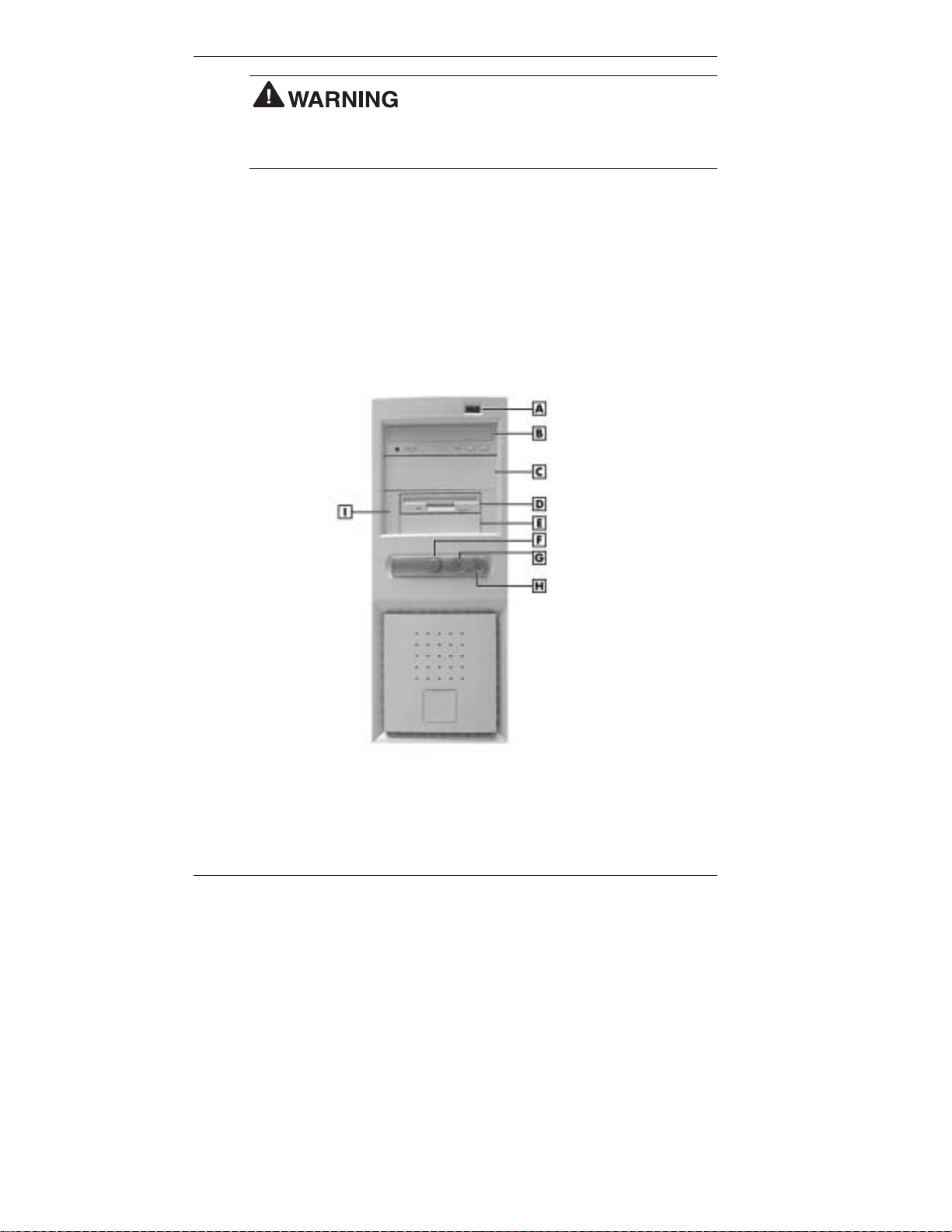
Front Features
You can use your PowerMate CT 815 system as a minitower or as a
desktop system. The following figures show the features on the front of
the system for both configurations. Brief descriptions follow the figures.
PowerMate CT 815 minitower front features
Prolonged or improper use of a computer
A
– USB Port
B – CD-ROM or DVD-ROM Drive G – Power/Sleep Lamp
C – 5 1/4-Inch Bay H – Disk Activity Lamp
D – Diskette Drive I – 3 1/2-Inch Accessible Device
E – 3 1/2-Inch Accessible
Device Bay
1-2 Reviewing System Features
F
– Power/Sleep Button
Bracket
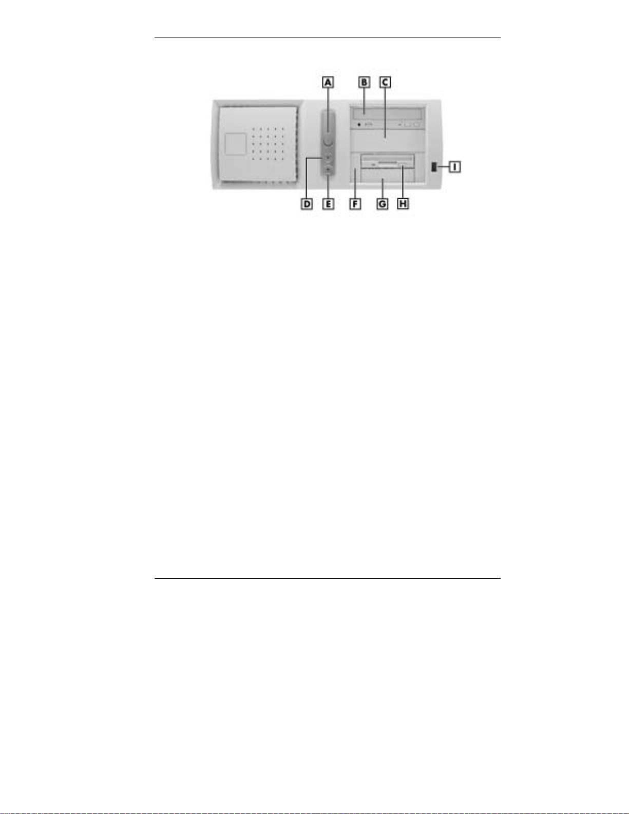
PowerMate CT 815 desktop front features
A – Power/Sleep Button F – 3 1/2-Inch Accessible Device Bracket
B – CD-ROM or DVD-ROM Drive G – 3 1/2-Inch Accessible Device Bay
C – 5 1/4-Inch Bay H – Diskette Drive
D – Power/Sleep Lamp I – USB Port
E – Disk Activity Lamp
System Controls and Lamps
System controls and lamps are identical for the minitower and desktop
systems. The controls and lamps include a power/sleep button,
power/sleep lamp, and hard drive activity lamp. The previous figures
show the controls and lamps on the front of the systems.
! Power/sleep button
Press this button to turn on system power. To turn off power, close all
applications, and shut down Windo ws. If you have Windows
Windows 2000, the system automatically powers down. If you have
Windows NT
®
, close all applications, shut down Windows NT, and
®
press in the button until the system powers down (about four seconds).
Press and immediately release the power/sleep button to suspend
system operation and go into a power sa ving mode. If you have a
VESA-compliant monitor, your monitor also goes into a power-saving
mode.
Press any key or move your mouse to resu me syste m oper a tio n at the
point where you stopped it.
Reviewing System Features 1-3
98 or
! Power/sleep lamp
The power/sleep lamp indicates whether system power is on or off. It
also lets you know if the system is operat ing in a power-saving mode.
A steady green lamp indicates that the power is on to all system
components. An unlit lamp indicates that power is not on.
A steady amber lamp and a blank monitor (VESA-compliant) screen
indicates that the system is in a power-saving (sleep) mode, with
full-power reduction.
! Hard drive lamp
A blinking lamp indicates that the hard drive is active. The blinking
lamp tells you that the hard drive is reading or writing data.
necessary while the hard drive lamp is lit. To do so can damage your hard
drive or data.
Diskette Drive
Use the diskette drive to copy data files to and from a diskette. You can
also use the diskette drive as a bootable drive for loading and starting
programs from a diskette.
Do not turn off the system unless absolutely
To prevent damage to your diskette drive and
data, do not turn off the system or remove a diskette while the diskette
drive busy lamp is lit.
Universal Serial Bus Port
The universal serial bus (USB) port on the front of the system allows you
to easily and conveniently add plug and play USB devices without
opening up the system. You simply plug the USB device into the port.
You can connect up to 127 devices including a mouse, monitor, keyboard,
printer, scanner, speakers, and more. Two additional USB ports are on the
rear of the system.
1-4 Reviewing System Features

CD-ROM Drive
Systems come with a 48X Max or higher variable speed compact disc
read-only memory (CD-ROM) drive. Use the CD-ROM drive to load and
start programs from a CD. You can also use the CD-ROM drive to play
your audio CDs.
The CD-ROM drive operates at different speeds depending on whether
the CD you are using contains data or music. This allows you to get your
data faster and to see smoother animation and video.
DVD-ROM Drive
Some systems come with a 16X or higher digital video disc (DVD)-ROM
drive. The drive offers many improvements over the standard CD-ROM
technology, including superior video and audio playback, faster data
access, and greater storage capacities.
The DVD-ROM drive uses DVD technology to read DVD discs as well as
standard audio and video CDs.
CD-RW Drive
Some systems come with an 8X (record) 4X (rewrite) 32X (read) compact
disk-rewritable (CD-RW) drive. Use the drive to record your data on a
CD-RW disc, just like you would on a diskette, Zip
®
disc, or hard drive.
With a CD-RW drive, you can erase what you have recorded o n th e
CD-RW disc and rewrite or record new data numerous times. CD-RW
discs are available that hold up to 650 MB of data (74 minutes of audio)
and up to 700 MB of data (80 minutes of audio).
You can read CD and DVD discs on the CD-RW drive. CD-RW discs can
be read on CD-ROM and DVD-ROM drives that support the MultiRead
Standard.
Zip Drive
Some systems come with a 250-MB capacity Zip drive. Use the Zip drive
with 3 1/2-inch Zip disks to back up work, archiv e ol d files , and transport
your work. The Zip drive supports 250-MB and 100- MB Zip disks .
Reviewing System Features 1-5
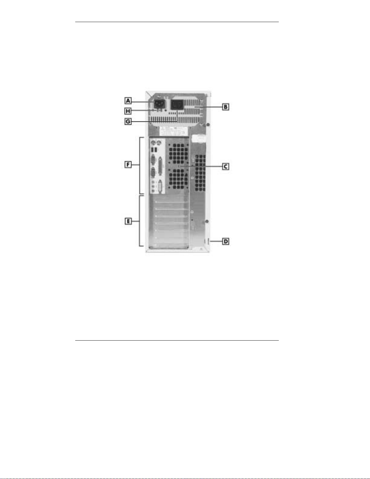
Rear Features
On the rear of your system, you’ll find the power supply socket, a monitor
power socket, a voltage switch, external connectors, and expansion board
slots. The following figures show these features.
PowerMate CT 815 minitower rear features
A
– AC Power Connector
B
– Power Supply
C
– Keyboard/Mouse Anti-Theft Bracket
D
– Cover Locking Tab
1-6 Reviewing System Features
E
– Expansion Slots
F
– System Board Connectors
G
– Monitor Power Socket
H
– Voltage Switch
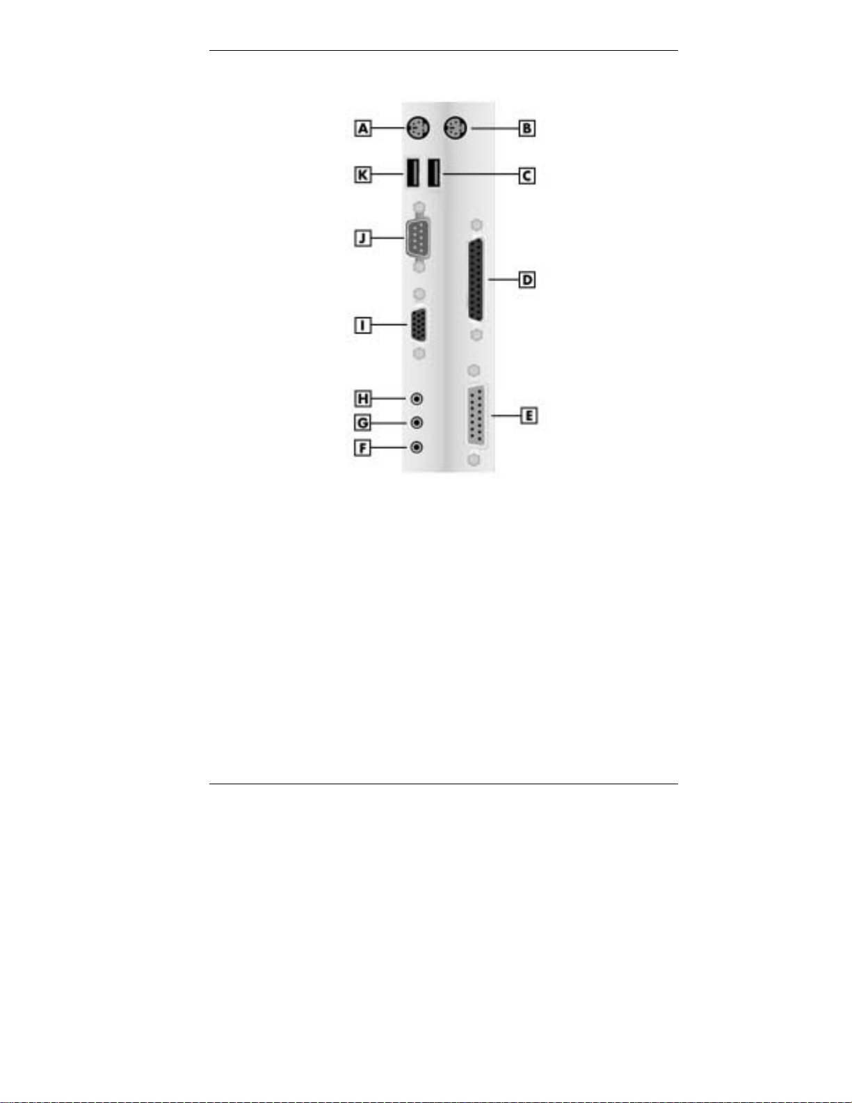
PowerMate CT 815 minitower rear connector locations
A – Keyboard Port G – Line In
B – Mouse Port H – Line Out
C – USB Port I – VGA Connector
D – Parallel Port J – Serial Port 1
E – MIDI/Game Port K – USB Port
F – Microphone In
Reviewing System Features 1-7
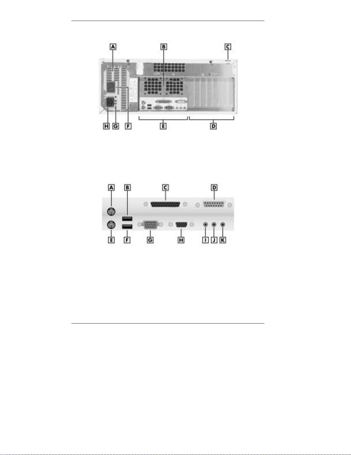
PowerMate CT 815 desktop rear features
A
– Power Supply
B
– Keyboard/Mouse Anti-theft Bracket
C
– Cover Locking Tab
D
– Expansion Slots
E
– System Board Connectors
F
– Monitor Power Socket
G
– Voltage Switch
H
– AC Power Connector
PowerMate CT 815 desktop rear connector locations
A
– Mouse Port
B – USB Port H – VGA Connector
C – Parallel Port I – Line Out
D
– MIDI/Game Port
E
– Keyboard Port
F
– USB Port
G
– Serial Port 1
J
– Line In
K
– Microphone In
1-8 Reviewing System Features

External Connectors
External connectors let you attach peripheral devices, such as a monitor,
keyboard, mouse, and printer to your system. Your system has the
following external connect ors .
! Mouse port
Attach the mouse that comes with your system to this port. The mouse
port supports a personal system/2-compatible (PS/2
mouse.
! Keyboard port
Attach the keyboard that comes with your system to the keyboard
port.
The keyboard port supports a PS/2-compatible 101-key or 104-key
keyboard (in the U.S. and Canada) or a 102-key keyboard (in the
United Kingdom and Germany) with a 6-pin mini DIN connector.
! Universal Serial Bus ports
Two USB ports add USB capability at the rear of the system. A third
USB port is on the front of the system.
! Serial port 1 (COM A)
Attach a serial device with a 9-pin connect or to this serial port. Serial
devices include a pointing device, serial printer, or a modem. Some
systems might ship with a second serial port (serial port 2, COM B)
installed in an expansion slot.
®
-compatible)
! Printer port
Use this port to connect a parallel printer with a 25-pin connector to
the system.
! VGA monitor connector
Attach the signal cable from your monitor to the VGA connector on
the rear of the system. Use this port to connect an NEC MultiSync
monitor, NEC AccuSync™ monitor, or o ther VGA-compatib le
monitor with a 15-pin conn ect or.
! MIDI/game port
Use this port to attach a musical MIDI device or a gaming device to
your syst em.
Reviewing System Features 1-9
®

! Audio connectors
The system co me s with sound integrated on the system board. The
following audio connectors are at the rear of the system (see the
preceding figure for locations).
— Microphone in jack
Use this jack to connect a microphone for recording audio
information in your data system files.
— Line in jack
Use this jack to connect a stereo audio device such as a stereo
amplifier or a cassette or minidisc player for playback or
recording.
— Line out jack
Use this jack to connect an amplified output device, such as
powered speakers or headset, a stereo tape recorder, or an external
amplifier for audio output.
! Fax/modem port
Some systems come with a V.90 rated 56-kilobits per second (Kbps)
PCI fax/modem board. The board allows the connection of a phone
line to the system for data communications functions.
! LAN port
Some systems come with a local area network (LAN) board or a
Communications and Networking Riser (CNR) board. Use the RJ-45
compatible LAN port on the board for connecting the system to an
Ethernet LAN.
Power Supply Features
Your system has the following power supply features:
! Power socket
Connect your power cable to this socket.
! Monitor power socket
If you have a plug adapter, plug the monitor power cable into this
socket instead of a wall outlet.
! Power supply fan
The power supply fan cools the power supply and other system
components to keep them from overheating. Keep the area near the
fan clear for proper ventilation.
1-10 Reviewing System Features
! Voltage switch
Sets the voltage for your system to 115 volts or 230 volts.
area. Most wall outlets in the United States and Canada are 115 volts.
Outlets in Europe are 230 volts.
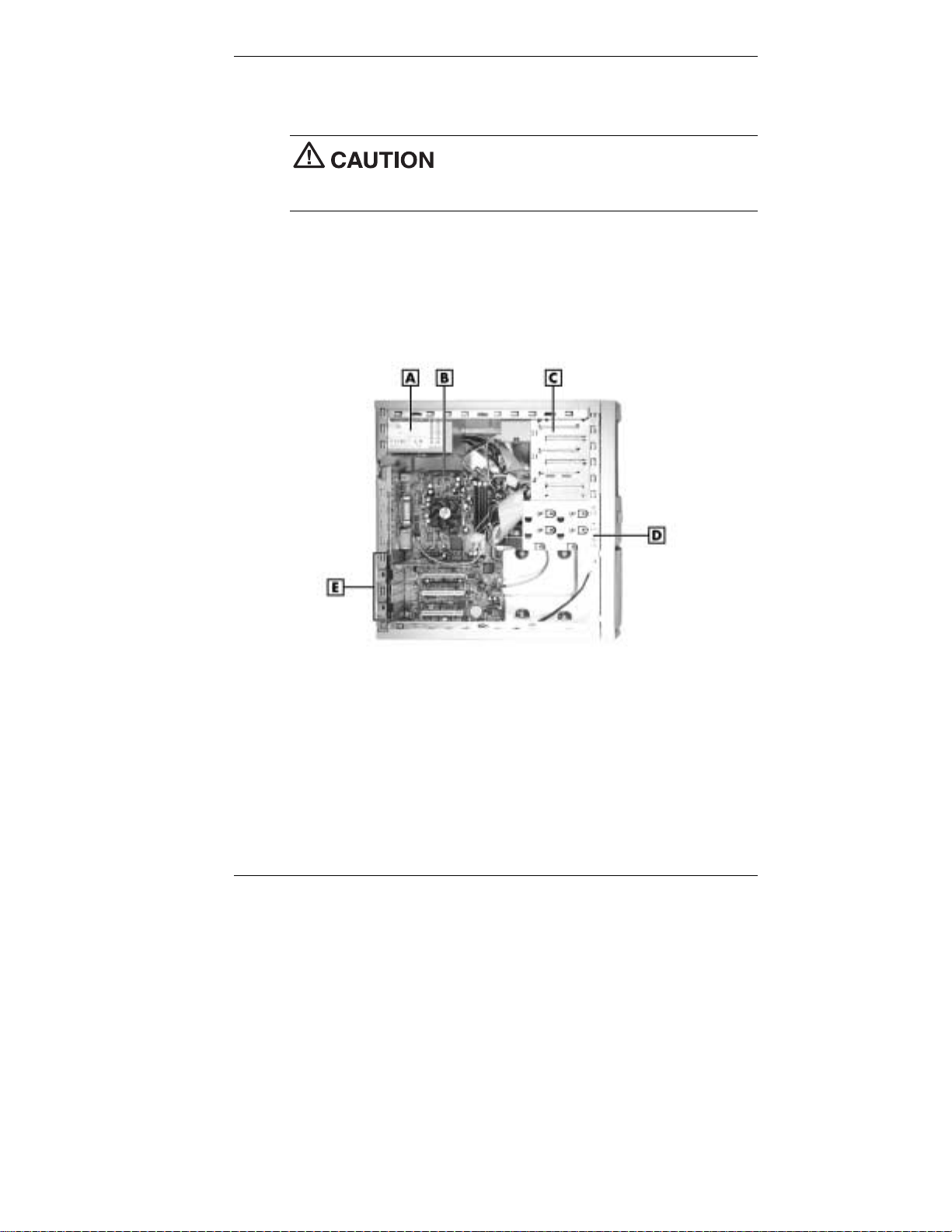
Inside Features
See the following figure for the location of major features within the
system. Feature descriptions follow.
Set the switch correctly for the voltage in your
Inside the syste m
A – Power Supply D – Internal Drive Bracket
B – System Board E – Expansion Board Slots
C – Accessible Device Cage
Reviewing System Features 1-11

System Board
The system processor, memory, system battery, internal connectors, and
most external connectors are on the system board. For information on the
external connectors, see “External Connectors” earlier in this chapter.
Internal connectors on the system board include:
! diskette drive connector
! primary and secondary IDE connectors that support up to four IDE
drives
! processor Socket 370 that supports Pentium III and Celeron processors
! three DIMM sockets
! three PCI connectors and one CNR connector for expansion boards
(expansion slots support up to three PCI boards or up to two PCI
boards and one CNR board)
! AGP board connector for AGP video and graphics boards
! CD audio connector for a CD-ROM or DVD-ROM drive
! digital flat panel/TV Out (DFP/TV) header for connecting an optional
DFP/TV board
! front panel connectors for system lamps and USB
! power connectors
! additional connectors, including Modem In (MDM), Auxiliary In
(AUX), Wake-On LAN (WOL), Wake-On Ring (WOR), case op en,
and CPU fan.
Power Management
Your system comes with Advanced Power Management (APM) a nd
Advanced Configuration and Power Interface (ACPI). Included as a
subset to ACPI is Instantly Available Technology.
APM features Soft Power Off, which automatically powers down your
system when you exit Windows 98 or Windows 2000 (not available for
Windows NT). This feature is enabled or disabled through your system’s
BIOS (see Chapter 3, “Configuring the System,” for Power Management
BIOS settings).
1-12 Reviewing System Features

Instantly Available Technology features the ACPI sleep mode which
maximizes power savings. When i n the sleep mode, your system appears
to be off. The power supply and fans are off and the power lamp is amber.
Pressing a key or moving the mo use ins t antl y wa ke s up your sys te m and
returns it to where you were before placing the system in the sleep mode.
This feature is enabled or disabled by setting jumpers on the system board
(see Chapter 3, “Configuring the System” for information on setting
system board jumpers).
If you have an optional internal or external modem installed, you can use
the Wake On Ring (WOR) and Resume On Ring (ROR) features of your
system. With WOR, your system can be powered up through the modem
from either the Soft Power Off or ACPI modes. The first call through the
modem powers on the system and a second call allows access to your
system.
The ROR feature allows a single call on your modem to resume system
operation and allow you system access. The ROR feature can be used
while the system is in the sleep mode or the ACPI power on state.
See Chapter 3, “Configuring the System,” for information on setting the
WOR and ROR features through the system’s BIOS. In addition, for the
WOR feature, a cable must be connected to the modem and to the WOR
connector on the system board.
Hard Drive
All systems come standard with a 10-GB or higher Ultra DMA 66/100
hard drive.
Network Board
Some systems come with an Intel® Ethernet 10/100 network PCI board, a
®
10/100 3C905C TX-M Ethernet network PCI board, or a CNR
3Com
network board.
Fax/Modem Board
Some systems come with a V.90 PCI fax/modem board installed in a PCI
slot. Connect your telephone line to this board.
Reviewing System Features 1-13

AGP Video Board
Some systems come with an AG P 4X video board. Conne c t your monitor
to the VGA connector on this board.
Chassis
The NEC convertible chassis conforms to the Intel ATX form factor
specification. The chassis has the following features:
! standardized chassis size and dimensions
! standardized system board size and dimensions
! standardized ATX 235-watt power supply with WOL capabilities
! switchable drive cage so system can be used in a minitower or desktop
orientation.
Note
Choose the position that best suits your space. See Chapter 4 for
procedures on converting your system to a different orientation.
Speakers
Some systems come with two high-quality stereo speakers. If the speaker
set has a volume control, a djust the speaker volume by using this control.
You can also use the Windows
To launch the Windows sound software, double click the speaker icon on
the taskbar (nex t to the system clock). Use the software to control speaker
volume or to balance the sound between the left and right speakers.
The system can be placed in the minitower or desktop position.
®
sound softwar e to control the speak ers.
1-14 Reviewing System Features

System Overview
Your system hardware and software deliver the performance and
technologies you need for all your challenging tasks today and into the
future. See the following sections for information about your system’s
hardware, software, and security features.
Hardware
The PowerMate CT 815 system includes the following hardware features:
! PC99 compliance
All the hardware in the system has been certified by Microsoft
PC99 compliant.
! Processor
The system comes with an Intel
®
Pentium® III 600-MHz or higher
processor with a 133-MHz or higher FSB. Processor speed and FSB
depends on the system configuration.
! Flashable ROM BIOS
The system’s ROM BIOS features system setup configuration, plug
and play support, and flash support for easy and economical BIOS
upgrades.
! System memo r y
Your system comes with at le as t 64 MB of non-E CC synchronous
dynamic random access memory (SDRAM). The system supports up
to 512 MB.
! Power management opti ons
The system comes with power management features that help you
conserve energy and reduce power costs (see “Power Management
Features” earlier in this chapter).
®
to be
Reviewing System Features 1-15

Software
NECC provides a variety of applications and hardware utilities with your
system to let you take advantage of your hardware capabilities.
Preloaded Software
Your system comes preloaded with the Microsoft® Windows® 98
operating system or th e Windows 2000/Windows N T
®
operating system
configuration.
If you have a Windows 2000/Windows NT configuration, you must
choose the operating system you want to load. The operating system you
choose is your only operating system and is the one that the NEC OS
Restore program restores.
NECC-provided applications, drivers, and utilities come loaded on the
hard drive. You can install some of your applications from icons on the
Windows desktop. Software available on your system includes the
following applications:
! Microsoft
®
Internet Explorer
Internet Explorer provides a top- notch browser with preloaded link s
for easy access to the world wide web. Also use Internet Explorer to
access one of the many new browser-based utilities.
! Norton AntiVirus™ 2000 Software
Protect your system from viruses by running Norton’s virus scan
software.
! Adobe
®
Acrobat® Reader
Use the Adobe Acrobat Reader to read and print portable document
format (PDF) files found on the Internet and PDF documents included
with various software applications.
! NEC INFO Center
Get quick access to information about your system in the online NEC
INFO Center. NEC INFO Center modules include Tour, User’s Guide,
Questions, Solutions, and Services. See “NEC INFO Center” in
Chapter 3 for a description of the modules and how to use the INFO
Center.
! Intel LANDesk
®
Client Manager
Use LANDesk software to track system information such as serial
number, BIOS version, memory capacity, disk capacity, expansion
board settings, and applications. Use LANDesk software for remote
starts from a server system using Wake-On LAN and remote reboot.
1-16 Reviewing System Features

NEC OS Restore CD
Your system comes with an NEC OS Restore CD and bootable diskette.
Should a problem occur that causes data loss or corruption, you can use
the NEC OS Restore CD to restore your system to its original factory state
or you can restore just the operating system and drivers. A full system
restore loads the operating system and all the factory-supplied software
that comes on your hard drive. See “NEC OS Restore CD” in Chapter 3
for information about using the restore options.
NEC Application and Driver CD
Use the NEC Application and Driver CD to install driver s for NEC
system options that are not part of the factory configuration. Also use the
NEC Application and Driver CD to reinstall NECC-supplied so ft ware.
See “NEC Application and Driver CD” in Chapter 3 for information about
installing software from the CD.
Security
The system has hardware, software, and mechanical security features that
offer protection against unauthorized access to your system and data. The
following security features are available with the system.
! Password securit y
The BIOS Setup Utility includes a feature that lets you set up a user
password, a supervisor password, or both.
The user password controls booting of the system and controls access
to the Setup Utility and the keyboard. (User access to the BIOS Setup
Utility is limited to a subset of all BIOS Setup parameters when a
supervisor password has been set.)
The supervisor password allows full access to the system and the
BIOS.
! Windows networ k se cur it y fea tur e s
To learn more about the network security features available through
the Windows operating system, refer to your Windows documentation
or consult yo ur system admini strator.
Reviewing System Features 1-17

! Keyboard/mouse anti-theft bracket
Secure the mo use and keyboard cables within the anti-theft bracket to
make it difficult to remove them from your system. See “Cover
Removal” in Chapter 4 for procedures on securing the cables in the
anti-theft bracket.
! Cover locki ng tab
The system also has a cover locking tab on the rear of the chassis. The
tab fits through a slot on the rear edge of the chassis cover when the
cover is on. When a padlock is used in the tab, th e syst em cover
cannot be removed and is physically protected from chassis intrusion.
! Chassis intrusion notification
Whenever the chassis cover is removed, a hidden switch sends a
signal to LANDesk Client Manager (LDCM). LDCM logs the incident
and then reports it on screen the next time the system is rebooted.
! Hard drive security
Your system supports password protection for the hard drive. Hard
drive password protection restricts access to the drive if the drive is
removed and installed in another system. The system does not prompt
for hard drive passwords while the drive remains in the current
system.
The passwords are written to the system BIOS and to the hard drive to
ensure that the password protection travels with the drive if it is
moved to another system. See Chapter 3, “Configuring the System,”
for additional information on using hard drive security.
1-18 Reviewing System Features

Setting Up the System
!
Chassis Orientation
!
Cable Connections
!
Startup
!
Shutdown
!
Power-Saving Operation
!
System Care
!
More Information
2

This chapter provides the basic information you need to set up and use
your system. This includes cable connections, system startup procedures,
system shutdown procedures, and system care. The chapter also includes
a chart showing where to find additional information about the system.
Chassis Orientation
The NEC PowerMate CT 815 system can be used either as a minitower or
as a desktop system. The accessible drives in the system can be positioned
to accommodate either orientation. Rubber feet on the system allow it to
rest securely at your work area when the system is in either position.
The system ships ready for use as a minitower system. You can easily
convert the system for use as a desktop. See “Minitower and Desktop
Setup Options” in Chapter 4 for instructions on convertin g to a desktop
orientation, or back to a minitower orientation.
Cable Connections
After unpacking the system, converting the system to the desktop
orientation (if desired), and pos itioning the system unit in your work area,
connect the system components using your Quick Setup poster and the
following tips.
! Use the icons on the rear of the system unit to ident ify the keyboard,
mouse, printer, USB, and monitor connectors.
! If the system comes with an optional LAN board, connect the LAN
cable to the RJ-45 connector on the board. See your network
administrat or for guid elines on configuring the system for network
access.
! If the system comes with an optional fax/modem board, connect it to
the telephone line as follows:
— Unplug the telephone from the telephone jack on the wall.
— Plug the telephone cable that comes with the system into the line
jack on the rear of the system and into the telephone jack on the
wall.
— Plug the cable on the telephone into the phone jack on the rear of
the system.
2-2 Setting Up the System

! For all other boards (CNR, DVI, AGP, sound), see the documentation
! Set the voltage switch correctly for your area. The correct setting for
! Connect system power cables to a surge protector (recommended) or a
to a surge protector.
Startup
Press the power button to start up your system. The power lamp lights
green to indicate that the system is on. The system performs its
Power-On Self-Test (POST). Several messages appear indicating that
your system is checking its subsystems. To see the messages, press
during POST.
provided with the board.
the U.S. and Canada is 115V.
Set the voltage switch correctly for your area.
properly grounded wall outlet.
NECC recommends connecting the power cable
Esc
At the bottom of the NEC startup screen, the following message appears:
Press F2 to enter BIOS Setup
If you want to enter the BIOS Setup, immediately press F2 while the
startup screen displays.
One beep indicates that the system has successfully completed the
power-on test.
After a short delay, Windows starts up.
If a problem occurs, a series of beeps may sound. If this happens
repeatedly after powering on, power off the system and turn to Chapter 5,
“Solving System Problems.” The chapter provides helpful hints for
solving system prob lems.
Setting Up the System 2-3

Note
have changed, run the BIOS Setup Utility (see Chapter 3, “Configuring the
System”).
On systems with Win dows 2000, enter your password at the log- on box.
On systems loaded with the Windows NT 4.0 operating system, press
Ctrl Alt Del
for entering a password.
Shutdown
Follow these steps to power off your system.
1.
If the system is in sleep mode (power lamp is amber and screen is
blank), press a key or move the mouse to take it out of sleep mode
(see “Power Saving Operation” in the next section).
2.
Save your work and exit all open application programs.
3.
Make sure that the hard drive, diskette drive, and any other drives are
not in use. A lit device lamp indicates that the device is in use.
before using the Windows shut down procedures in step 4.
Unless absolutely necessary, never power off the system if the system
power lamp is amber (sleep mode), if the hard drive lamp, diskette drive,
or other device lamp is flashing, or if any applications are open.
Information on the device might be lost or damaged.
If the system displays a message indica tin g that syst em setti ng s
when prompted on-screen to do so. The log-on box appears
Wait until all applications are saved and closed
4.
Start
Click
Shut down the computer
on the taskbar, then point to and click
down.
! If the system is configured with Windows 98 or Windows 2000,
the system shuts down automatically after a short interval.
! If your system is configure d with Windows NT, perform a
Windows shutdown, then power off the system by pressing and
holding in the power button for four seconds or longer.
5.
Turn off power to your monitor.
2-4 Setting Up the System
, then click
Yes
or press
Shut Down
Enter
for shut
. Select

Power-Saving Operation
If the system is running Windows 98 or Windows 2000, you can put it in
sleep mode (a power-saving state) by pressing and immediately releasing
the power button on the front of the system unit. The sleep mode is a way
of conserving energy if you are away from your system for a short period
of time. (See “Power Management” in Chapter 1 for additional
information on saving power.)
Take care to press and immediately release the
power button to enter the sleep mode. Avoid pressing and holding in the
power button longer than three seconds. If you do so, you might turn off
power and lose data from any open applicatio n.
The system also goes into sleep mode when it has been inactive, if the
power management has been enabled, and an inactivity timeout has been
enabled. To see if power management is enabled, click
Settings,
Click the
setting other power management functions.)
When the system goes into sleep mode, it saves data and system status
and then shuts of f power to all possible components. S l eep mode lets you
save power without first saving your work.
Control Panel
click
Power
tab and check the settings. (Also see Chapter 3 for
, and double click
Start
, point to
Power Management
.
An amber power lamp and a blank screen indicates that the system is in
sleep mode. Press a key or move the mouse to resume system operation
where you left o ff.
System Care
Your system is a durable, dependable system built for heavy use. With
protective measures and proper care, you can prevent problems and
promote the successful operation and long life span of your system.
Setting Up the System 2-5

Protecting Your System From Damage
There are several ways that you can protect your system from possible
damage. NECC strongly recommends the following protective measures.
! Connect a surge suppressor between your system and a grounded wall
outlet. A surge suppressor protects your system from sudden transient
increases and decreases in electrical power.
Be sure to connect all peripherals, such as your monitor and printer, to
the surge suppressor. T he surge protec t or should be the only device
that you plug into the wall outlet.
! Avoid repeated power-on cycles. These sub j ect the system
components to temperature variations and stress.
! Disconnect your system from tel ephone and power lines when an
electrical storm threatens. If you have a fax/modem, lightning can
travel in on the phone line and damage both the fax/modem and the
system unit. L ightning can also trav el in on power lin es and damag e
your monitor and system unit.
! Be sure that system power is off before you connect or disconnect a
cable. Never make cable changes when the system power is on. Doing
so can damage the system and its peripherals.
! Use your Norton AntiVirus 2000 detection software regularly to
protect your system from system viruses.
If you plan to load software programs other than the ones NECC
supplied on the Application and Driver CD, NECC strongly
recommends that you take the necessary steps, such as virus checks, to
protect your system.
! Position your system away from direct sunlight and extreme hot and
cold temperatures.
The recommended operating environment is from 41°F to 95°F (0°C
to 35°C).
The recommended non-operating env ironment (shipping or storage) is
from 14°F to 158°F (-10°C to 70°C).
! After turning off power, wait about five seconds for the hard drive to
spin down before you power on again .
2-6 Setting Up the System

! Be sure that nothing is placed on top of your system power cables.
! Prevent dust from entering your system by covering it when it is not in
use.
Keeping Your System in Good Condition
Maintain the condition of your system by periodically using the following
procedures.
For safety, power off and unplug your system,
monitor, and any external devices before cle aning them.
! Clean the outside of the system with a soft clean cloth.
You can remove stubborn stains with a cloth slightly dampened with a
mild detergent. Never use a strong cleaner or solvent on any part of
the system.
! Keep food and liquids away from your system.
! Periodically clean the keyboard with a vacuum cleaner brush
attachment. Do not use any liquid cleaners on the keyboard as they
can damage the keyboard.
If an object, such as a paper clip, falls into the keyboard, turn the
keyboard over and gently shake it.
! Clean the monitor screen with a glass cleaner and wipe it with a clean,
lint-free cloth. You can use wet/dry clean ing pads manufactured for
monitor screens.
Moving or Shipping Your System
Use these steps to prepare your system for moving or shipping.
1.
Back up the files on the hard drive to diskettes, Zip disks, CD-RW
discs, tape cartri dges, server hard drives, or other backup devices.
Take precautions for storing and transporting diskettes, Zip disks,
CD-RW discs, or tape cartridges so that they are not exposed to
magnetic fields or electr ica l impu lses .
Setting Up the System 2-7

2.
Remove all removable media from your drives, including CDs,
DVDs, CD-RW discs, diskettes, Zip disks, and tape cartridges.
3.
Turn off the system unit and any external options connected to it.
4.
Unplug the system unit power cable from the wall outlet or surge
suppressor, then from the unit its elf.
5.
Unplug any external options from the wall outlets or surge
suppressor, then disconnect them from the system unit.
6.
Pack the system components in the original shipping materials and
cartons. If these are not available, be sure to use adequate packing
materials to protect the components.
To set up your system, fo llow the steps on the PowerMate CT 815 Quick
Setup poster that comes with the system.
More Information
Once you have your system up and running, we suggest that you do the
following:
! Install applications provided by NECC.
! See “Setting Up a Healthy Work Environment” in Appendix A.
! Install any of your own applications. See the documentation that
comes with the application.
See the following quick reference chart to find information about using
the system.
2-8 Setting Up the System

Quick Reference to Information About Your System
Information Where to Find It
Accessing the world wide web Chapter 6
Adding system upgrades Chapter 4
Configuring your system Chapter 3
Converting the system to a desktop
configuration
Converting the system to a minitower
configuration
Installing the NEC INFO Center online
documentation
Protecting the system from viruses Chapter 1, Chapter 3
Reinstalling the applications prov ide d
by NECC
Setting a password Chapter 3
Setting up your system Chapter 2
Taking care of the system “System Care” in Chapter 2
Troubleshooting tips Chapter 5
Using support services Chapter 6
“Converting from Minitower to
Desktop” in Chapter 4
“Converting from Desktop to
Minitower” in Chapter 4
“NEC INFO Center” in Chapter 3
“NEC Application and Driver CD” in
Chapter 3
Setting Up the System 2-9

Configuring the System
!
Configuration Tools and Utilities
!
BIOS Setup Utility
!
Hard Drive Security
!
Flash Utility
!
NEC INFO Center
!
NEC Application and Driver CD
!
NEC OS Restore CD
!
System Board Jumper Settings
!
Intel Processor Serial Number Control Utility
3

This chapter provides information on configuring your system. The
chapter includes information on:
! Americ an Megat rends Inc. (AMI) BIOS Setup Utility for configuring
your syst em
! hard drive security for password protection of the internal hard drive
! FLASH Utility for BIOS updates
! NEC INFO Center for quick access to information about your system
! NEC Applications and Driver CD for installing the NECC-supplied
applications and installing optional drivers
! NEC OS Restore CD for resto ring the operating syst em
! jumper settings for setting various system configurations.
! Intel Processor Serial Number Control Utility for controlling the
reading of the processor serial number.
See the following table for a quick guide to the utilities, tools, or
procedures required for configuring the system. For detailed information
about these and other tools, see the sections following the table.
Configuration Tools and Utilities
The following table lists ways you can configure the system, and the
utility, tool, or procedure to use for the configuration.
Configuration Tools and Utilities
Configuration Method, Tool, or Utility
BIOS, updating FLASH Utility
Boot devices, determining BIOS Setup (Advanced Menu)
Boot order, changing BIOS Setup (Advanced Menu)
Clearing CMOS Jumper Settings
Configuring jumpers on syst em board Jumper Settings
Diskette drive, enabling BIOS Setup (Main Menu)
3-2 Configuring the System

Configuration Tools and Utilities
Configuration Method, Tool, or Utility
Drivers for NECC hardware, installing NEC Application and Driver CD
Hard drive, setting a pre-delay BIOS Setup (Advanced Menu)
Hard drive, setting password protection BIOS Setup (Security Menu)
Inactivity timeout, setting BIOS Setup (Advanced Menu)
NEC INFO Center, installing NEC INFO Center
NEC INFO Center, uninstalling NEC INFO Center
Operating system, restoring NEC OS Restore CD
Parallel port, enabling, configuring BIOS Setup (Advanced Menu)
Password, setting or clearing (user,
supervisor, or both)
Plug and Play, enabling BIOS Setup (Advanced Menu)
Power management, enabling,
configuring
Serial ports, enabling BIOS Setup (Advanced Menu)
Software, reinstalling (NECC provided) NEC Application and Driver CD
Sound, enabling BIOS Setup (Advanced Menu)
Time and date, setting BIOS Setup (Main Menu)
USB functions BIOS Setup (Advanced Menu)
Windows 98, Windows NT,
Windows 2000, restoring
BIOS Setup (Security Menu)
BIOS Setup (Advanced Menu)
NEC OS Restore CD
Configuring the System 3-3

BIOS Setup Utility
The AMI BIOS Setup Utility program is used to configure the main
components of your sy stem.
Your system ships from the factory with the correct system parameters for
your configuration. Unless you add optional hardware, you do not need to
run the BIOS Setup Utility to operate the system. However, you might
wish to run the Setup Utility to set features that customize the system,
such as security features.
System configuration information is stored in nonvolatile memory. A
nonvolatile memory device retains its data when system power is turned
off. Nonvolatile memory in your system is stored in a complementary
metal-oxide semiconductor (CMOS) memory chip backed up by a battery
on the system board. The battery supplies continuous power to CMOS
memory and maintains configuration information when system power is
off.
NECC recommends that you print out or write down your current BIOS
Setup parameters and store the information in a safe place. This lets you
restore your system to the current parameters if you ever need to replace
the battery (see “How to Replace the CMOS Battery” in Chapter 5).
How to Start BIOS Setup
To start the BIOS Setup Utility, follow these steps.
1.
Turn on or reboot the system.
2.
Press F2 as soon as you see th e following message at th e bottom of
the NEC startup screen.
<F2 for BIOS Setup>
You have about five seconds to pr e ss F2 before the system boot
continues.
Setup’s Main Menu appears.
3-4 Configuring the System

How to Use Setup
The Setup Utility has a Main Menu window and four top-level menus
with submenus. The menu bar at the top of the Main Menu window lists
the following top-level menus.
! Main Use the Main Menu for basic system configuration. For
example, select Main to set the system date, set diskette and hard disk
parameters, or set the hard drive auto-detect feature.
! Advanced Use the Advanced Menu to set up the system for
advanced CMOS, advanced chipset, power management, Plug and
Play, serial and parallel peripherals, and hardware monitor.
! Security Use this menu to set User and Supervisor Passwords and
password check.
! Exit Exits the Setup Utility with various save or discard o p tions.
Use the keys listed in the lege nd bar on the bo ttom of the menu screen to
make the selections or exit the current menu. Help Setup information is
displayed on the right side of the menu screen.
The following table describes the lege nd keys.
Navigation Keys
Key Function
Esc Exits the menu.
Enter Executes Command or brings up a
submenu.
F1 Press this key on any menu for help.
F5 Loads default values.
F6 Loads setup original values.
F10 Saves changes and Exits the BIOS Setup
Utility.
Up or down arrow keys Moves cursor up and down in the menu.
Configuring the System 3-5

Navigation Keys
Key Function
Left or right arrow keys Selects next menu.
+
/PgUp
–/PgDn
To select one of the four menus from the menu bar, use the left and right
arrow keys. Use the up or down arrow keys to select an item under the
menu.
Menu items preceded by a > contain a submenu of selectable fields for
setting system parameters. Display a submenu by using the up or down
arrow keys to move the cursor to the desired submenu, then press
An Item Specific Help window on the right side of each menu displays
the help text for the currently selected Setup option. It updates as the
cursor moves to each new field.
Pressing
describes the legend keys and their functions.
Press
The following subsections describe the four top-level menus and their
submenus.
Main Menu
Increases numeric values or makes
changes.
Decreases numeric values or make s
changes.
F1
on any menu brings up the General Help window that
Esc
to exit the current window.
Enter
.
Choose the Main Menu by selecting Main in the legend bar on the Main
Menu screen. Other Main Menu options are available by selecting
submenus.
Use the arrow keys to select one of the Main Menu options and press
Enter
to select a submenu. Items with grayed-out text are not available.
Explanations of each Main Menu item are in the following table.
3-6 Configuring the System

Setting items on this menu to incorrect values
can cause your system to malfunction.
Main Menu Items
Menu Item Settings (default is bold)
System Date
System Time
Floppy Drive A Not Installed
Floppy Drive B
Set system date in this field. Press Tab or Enter
to move between month, date, and year fields.
Example: 10/20/2000
Set system time in this field. Press Tab or Enter
to move between hour, minute, and second
fields.
Example: 09:30:50
360 KB 5 1/4"
1.2 MB 5 1/4"
720 KB 3 1/2"
1.44 MB 3 1/2"
2.88 MB 3 1/2"
Not Installed
360 KB 5 1/4"
1.2 MB 5 1/4"
720 KB 3 1/2"
1.44 MB 3 1/2"
2.88 MB 3 1/2"
Configuring the System 3-7

Main Menu Items
Menu Item Settings (default is bold)
Primary IDE Master
Primary IDE Slave
Secondary IDE Master
Secondary IDE Slave
Type
Auto, User Type, Not Installed
Auto, User Type, Not Installed
Auto, User Type, Not Installed
Auto, User Type, Not Installed
Each device menu item displ ay s the hard driv e or
CD-ROM identifier if a device is installed.
If you install a hard drive that does not feature
auto IDE type detection or your IDE hard drive
was formatted on another system with
parameters different from those reported by the
drive, enter a parameter for each of the fields in
the device submenu.
Bring up a device submenu by pressing Enter.
Each is briefly described in the following.
Auto, User, CD-ROM, Floptical, Not Installed,
1-46
When set to Auto, the BIOS sets the correct
values for the device, including Cylinders, Heads,
Write Precompens ation, Sectors, Maximum
Capacity, Fast Programmed I/O Mode, 32 Bit
Transfer Mode, LBA Mode, and Block Mode.
Selecting User allows you to configure the BIOS
for the device selected. The Not Installed setting
indicates that there is no IDE device present in
the system.
Depending on the option selected, one of the
following submenus displays .
Cylinders When Type is Auto, value in the cylinders field is
auto-detected and field is read only.
Heads
When Type is Auto, value in the Heads field is
auto-detected and field is read only.
3-8 Configuring the System

Main Menu Items
Menu Item Settings (default is bold)
Write
Precompensation
Sectors When Type is Auto, value in the Sectors field is
Maximum Capacity When Type is Auto, value in the Maximum
Fast Programmed I/O
Modes
32 Bit Transfer Mode
LBA Mode
Block Mode
When Type is Auto, value in the Write
Precompensation field is auto-detected and field
is read only.
auto-detected and field is read only.
Capacity field is auto-detected and field is read
only.
Auto, 0 -5
Use these settings to configure the Advanced
PIO Mode.
On, Off
When On, allows 32 bit IDE data transfers.
Should only be On if supported by a chipset
controller.
On, Off
When On is selected, it causes logical block
addressing to be used in place of cylinders,
heads, and sectors.
On, Off
When On is selected, it allows block mode data
transfers.
Auto Detect Hard Drives
CPU Speed xxx MHz
Press Enter
Auto detects all hard drive parameters.
Not selectable, displays information only.
Configuring the System 3-9

Main Menu Items
Menu Item Settings (default is bold)
Front Side Bus Speed xxx MHz
Not selectable, displays information only.
Memory Size xxx MB
Not selectable, displays information only.
Memory Speed xxx MHz
Not selectable, displays information only.
BIOS Version
Advanced Menu
Choose the Advanced Menu by selecting Advanced in the legend bar on
the Main Menu screen. Other Advanced Menu options are available by
selecting submenus.
Use the arrow keys to select an Advanced Menu option. Press
display the submenu. Items with grayed-out text are not available.
Explanations of each Advanced Menu item are in the following table.
can cause your system to malfunction.
Axxxxxx
Not selectable, displays information only.
Setting items on this menu to incorrect values
Enter
to
3-10 Configuring the System

Advanced Menu - Advanced CMOS Setup
Menu Item Settings (default is bold)
View DMI Event Log
Clear all DMI Events
Logs
Event Logging
Mark DMI Events as
Read
Status only. Press Enter to view.
No, Yes
Selecting No prevents clearing out the DMI events
logs.
Enabled, Disabled
Selecting Enabled permits event loggin g.
Press Enter (Yes/No)
Press Enter to mark DMI event log as read.
Advanced Menu - Advanced Configuration
Menu Item Settings (default is bold)
Quick Boot
Delay for Hard Drive
(seconds)
Enabled, Disabled
When Enabled, the BIOS does not test system
memory above 1 MB or wait for ready signals,
allowing a quick boot.
3, Disabled, 1 -10
Selects the amount of time for hard drive delay.
1st Boot Device
2nd Boot Device
3rd Boot Device
Floppy, Disabled, IDE-0, IDE-1, IDE-2, IDE-3,
LS-120/Zip, ATAPI Zip, CDROM, SCSI, Network
Sets the floppy drive as the first boot device.
IDE-0
Sets the hard drive as the second boot device.
CDROM
Sets the CD-ROM drive as the third boot device.
Configuring the System 3-11

Advanced Menu - Advanced Configuration
Menu Item Settings (default is bold)
Try Other Boot Devices
Floppy Access Control
S.M.A.R.T. for Hard
Disks
Boot-up Num-Lock
Boot to OS/2>64 MB
CPU Serial Number
Yes, No
Select Yes to cause the system to try to boot from
other boot devices if there is a boot failure. Selecting
No causes the boot to be carried out from selected
devices.
Read-write, Read-only
Select Read-write to allow the diskette drive to have
read-write capabilities.
Disabled, Enabled
Select Enabled to use the Self Monitoring Analysis
and Reporting Technology (S.M.A.R.T.) for reporting
a possible problem with an IDE device. After
receiving the warning, the BIOS alerts you to the
problem.
Off, On
Select On to lock the numeric keypad on boot up.
No, Yes
Select Yes to enable a boot to OS/2 if RAM is greater
than 64 MB.
Disabled, Enabled
Controls detection of the processor serial number.
3-12 Configuring the System

Advanced Menu - Advanced Chipset Setup
Menu Item Settings (default is bold)
USB Function
USB Keyboard/Mouse
Legacy Support
Memory Hole
ClkGen Spread
Spectrum
ClkGen for PCI
Slot/DIMM
Enabled, Disabled
Select Enabled to enable use of USB functions for
USB devices.
Enabled, Disabled,
Select Enabled to enable the USB functions for a
USB keyboard and mouse.
15MB-16MB, Disabled
Select 15MB-16MB to reserve a space in the
memory, between 15 and 16 MB, for certain ISA
boards.
Disabled, Enabled
Select Enabled to enable the Clock Generator
Spectrum and limit the risk of electromagnetic
emissions.
Disabled, Enabled
Select Enabled to enable the Clock Generator for PCI
and DIMM slots.
Configuring the System 3-13

Advanced Menu - Power Management Setup
Menu Item Settings (default is bold)
ACPI Standby State S1/POS, S3/STR
Select S1/POS for a low wake-up latency sleeping
state. In the S3/STR mode, the CPU, cache, and
chipset contexts are lost.
USB Keyboard Wakeup
From S3
Power
Management/APM
Suspend Time Out
(Minutes)
Power Button Function
Restore on AC/Power
Loss
Disabled, Enabled
Select Enabled to allow the system to wake up fr om a
keyboard input when in S3 mode.
Enabled, Disabled
Select Enabled to enable Power Management and
Advanced Power Management (APM).
Disabled, 1, 2, 4, 8, 10, 20, 30, 40, 50, 60
Specifies duration of system inactivity while in
Standby state before entering Suspend power state.
Suspend, On/Off
Suspend sets the power switch for Suspend (Sleep)
mode. With power on, pressing the switch once
places the system in sleep mode. Pressing and
holding the switch in for 4 seconds turns power off.
Last State, Power Off, Power On
The Power On setting automatically turns power on
after a power loss. The Power Off setting requires the
user to restart the system with the power button. The
Last State setting restores the system to the state
where it was on power loss.
Resume on Ring
Disabled, Enabled
The Enabled setting automatically reboots the system
when a signal is sent through a modem.
3-14 Configuring the System

Advanced Menu - Power Management Setup
Menu Item Settings (default is bold)
Resume on LAN
Resume on RTC Alarm
RTC Alarm Date 15, Every Date
RTC Alarm Hour 12, 1-00
RTC Alarm Minute 30, 0-59
RTC Alarm Second 30, 0-59
Disabled, Enabled
The Enabled setting automatically reboots the system
when a signal is sent through a LAN.
Disabled, Enabled
When Enabled, you can choose the time the system
boots up (see the following time setting s).
Sets the day that the system boots up (when Resume
on RTC Alarm is Enabled).
Sets real time clock alarm hour (when Resume on
RTC Alarm is Enabled).
Sets real time clock alarm minute (when Resume on
RTC Alarm is Enabled).
Sets real time clock alarm second (when Resume on
RTC Alarm is Enabled).
Configuring the System 3-15

Advanced Menu - Plug and Play Setup
Menu Item Settings (default is bold)
Plug and Play Aware
O/S
Clear NVRam
Primary Graphics
Adapter
PCI VGA Palette Snoop
DMA Channel
0, 1, 3, 5, 6, 7
IRQ 3, 4, 5, ,7, 9, 10,
11, 14, 15
No, Yes
Select No to allow the BIOS to initialize any add-on
boards. Select Yes to allow the operating system to
initialize any add-on boards.
No, Yes
Select No to prohibit clearing of NVRam.
Auto, Internal, External AGP, External PCI
Allows selection of the Primary Graphics Adapter as
an add-on board or onboard.
Disabled, Enabled
Set to Enabled to enable PCI VGA palette snooping.
PCI/PnP, ISA
Permits configuring the DMA channels either by
PCI/Plug and Play or by ISA.
PCI/PnP, ISA
Permits configuring the interrupt requests either by
PCI/Plug and Play or by ISA.
3-16 Configuring the System

Advanced Menu - Peripheral Setup
Menu Item Settings (default is bold)
AC’97 Audio Controller
AC’97 Modem
Controller
Onboard Serial Port A
Serial Port A Mode
Onboard Serial Port B
Serial Port B Mode
Onboard Parallel Port
Enabled, Disabled
The Enabled setting allows use of onboard sound.
Enabled, Disabled
The Enabled setting allows use of onboard telephony.
Auto, 3F8/COM1, 2F8/COM 2, 3E8/COM3,
2E8/COM4, Disabled
Defines serial port A base I/O address.
Normal, IrDA, ASKIR
Select Normal to set the port for normal use.
Auto, 3F8/COM1, 2F8/COM2, 3E8/COM3,
2E8/COM4, Disabled
If serial port B is installed, select 2F8/COM2 as the
serial port B base I/O address.
Normal, IrDA, ASKIR
Select Normal to set the port for normal use.
378, 278, 3BC, Auto, Disabled
Select Auto to allow the BIOS to automatically assign
the parallel port to an available parallel port IRQ.
Parallel Port Mode
Parallel Port IRQ
EPP, ECP, Normal
Use this mode to choose the operating mode of the
onboard parallel port.
7, 5, Auto
Allows setting of the interrupt request (IRQ) for the
parallel port.
Configuring the System 3-17

Advanced Menu - Peripheral Setup
Menu Item Settings (default is bold)
Parallel Port Mode DMA
Channel
OnBoard MIDI Port
MIDI IRQ Select
OnBoard Game Port
0, 1, 3, Auto
Allows you to choose DMA channel for the onboard
parallel port in ECP mode. Displays only when
parallel port is enabled and in ECP mode.
Disabled, 300, 330
Allows you to configure or disable onboard MIDI port.
IRQ 9, IRQ 5, IRQ 7, IRQ 10
This allows you to select the IRQ for the MIDI port.
201, 209, Disabled
This allows you to configure or disable the onboard
game port.
Advanced Menu - Hardware Monitor Setup
Menu Item Settings (default is bold)
ACPI Shut Down
Temperature
Disabled
60°C/140°F
°
65
F/149°F
70°F/158°F
75°F/167°F
ACPI gives the operating system direct control over
the power management and Plug and Play functions
of a computer. The system shuts down at the
temperature indicated.
Reset Case Open
Status
Reset, Disabled, Enabled
Case status is reset.
3-18 Configuring the System

Advanced Menu - Hardware Monitor Setup
Menu Item Settings (default is bold)
Case Status Opened, Closed
CPU Temperature
CPU Fan Speed
Chassis Fan Speed
Power Fan Speed
CPU VID
Vcore
Vtt
Vcc3
+5.000V
+12.000V
-12.000V
-5.000V
Battery
+5V SB
Security Menu
Choose the Security Menu by selecting Security in the legend bar on the
Main Menu screen. Other Security Menu options are available by
selecting submenus.
Use the arrow keys to select one of the Security Menu options and press
Enter
to select a submenu. Items with a grayed-out text are not available.
Explanations of each Security Menu item are in the following table.
The BIOS detects the value for each of these
categories automatically and monitors them
accordingly.
Configuring the System 3-19

Security Menu Items
Menu Item Settings (default is bold)
Set Supervisor
Password
Set User Password [Enter]
Password Check Setup, System
Assign HDD Password
[Enter]
Use this field to set or change the supervisor
password. Press Enter to bring up a dialog box
where the password can be entered and confirmed.
Use this field to set or change the user password.
Press Enter to bring up a dialog box where the
password can be entered and confirmed.
Allows the user to determine when a password is
needed. Selecting Setup requires a password for
entering the BIOS Setup Menu. Selecting System
requires a password every time the system is turned
on.
Press Enter to access the Assign HDD Password
Mode.
Controls access to the system’s hard driv e by
assigning master and user passwords. See “Hard
Drive Security” later in this chapter for information
and procedures for using the HDD password mode.
CAUTION: If the master and user password are set
on a hard drive, they can never be removed. If the
master password is forgotten and the hard drive is
installed in another system, data cannot be accessed
on the hard drive.
Once these passwords are set, NEC Computers
Inc. has no capability to remove them.
3-20 Configuring the System

Exit Menu
Choose the Exit Menu by selecting Exit in the legend bar on the Main
Menu. Other Exit Menu options are available by selecting submenus.
Use the arrow keys to select one of the Exit Menu options and press
to display the submenu. Explanations of each Exit Menu item are in the
following table.
Exit Menu Items
Menu Item Settings (default is bold)
Exit Saving Changes Implements the changes just made, and exits BIOS.
Exit Discarding
Changes
Load Default Settings Reverts to the factory set default settings.
Load Original Values Reverts to the factory set original settings.
Reverts to the settings from before the BIOS session.
Hard Drive Security
Your NEC PowerMate CT 815 system allows establishing password
protection for the internal hard drive. Hard disk drive (HDD) password
protection restricts access to the drive only if the drive is removed from
the PowerMate CT 815 system and installed in another system. The
system does not prompt you to enter your HDD passwords while the drive
remains in the current system.
Enter
The HDD passwords are written to the system BIOS and to the hard drive
to ensure that the password protection travels with the drive if it is moved
to another system.
Establishing Hard Disk Drive Passwords
To establish password protection for the system’s hard drive, you must
establish a master password, establish a user password, and enable the
established passwords for the internal hard drive. Use the following
procedure to establish HDD passwords and to enable HDD password
protection.
Configuring the System 3-21

If you set the master and user password on a
hard drive, you can never remove the passwords. You can change the
passwords. If you forget the master password and install the drive in
another system, you cannot access the data on the hard drive.
Once you set these passwords, NEC Computers Inc. has no
capability of removing them.
If you install the hard drive in another PowerMate system with hard disk
drive security enabled, you must enter the password to allow access to the
hard drive. If this PowerMate system does not support hard disk drive
security, you cannot access the data on the hard drive.
1.
Boot your system. Press F2 when prompted to enter BIOS Setup. The
Main Menu screen appears.
2.
Using the arrow keys, select the Sec urity Menu.
3.
Use the down arrow key to highlight
Enter
press
4.
Enter a master HDD password and press
. The system prompts you to enter a master password.
Assign HDD Password
you to reenter the password to verify.
5.
Reenter the master HDD password and press
confirms the creation of the master password and prompts you to
enter a user password.
6.
Enter a user password and press
Enter
reenter the password to verify.
7.
Reenter the user pa ssword and press
8.
Highlight and select
Primary Master HDD Password
Enter
+ (plus) and – (minus) keys to enable the selection. (This enables
password protection for the internal HDD.)
Changing Hard Disk Drive Passwords
Use the following procedure to change hard disk drive passwords.
1.
Boot your system. Press F2 when prompted to enter BIOS Setup.
2.
At the Ma in Menu s creen, se lect the S e curity Men u.
and
Enter
. The system prompts
Enter
. The system
. The system prompts you to
.
. Use the
3-22 Configuring the System

3.
Highlight
! If you enter the current master password, you are prompted to
Assign HDD Password
and press
Enter
enter a new master password.
! If you enter the current user password, you are prompted to enter
the new user password.
! If you do not want to establish a new master or user password,
Esc
press
4.
Save the changes and exit BIOS Setup.
instead of entering a new password.
Using Hard Disk Drive Password Protection
To facilitate the transfer of one or more HDDs between systems, establish
a single master password (and store the password in a secure place).
Forgetting the master password results in the inability to access the data
on the hard drive. Establish different user passwords to limit access to
specific systems.
If you set the master and user password on a
hard drive, you can never remove the passwords. You can change the
passwords. If you forget the master password and install the drive in
another system, you cannot access the data on the hard drive.
Once you set these passwords, NEC Computers Inc. has no
capability of removing them.
If you install the hard drive in another PowerMate system with hard disk
drive security enabled, you must enter the password to allow access to the
hard drive. If this PowerMate system does not support hard disk drive
security, you cannot access the data on the hard drive.
.
With hard disk drive security enabled on the original NEC PowerMate CT
815 system, the system boots normally.
If you install the hard drive in another NEC PowerMate system with
security enabled, you must enter the master password to access the hard
drive. If the hard drive is installed in another NEC PowerMate CT 815
system with security disabled, the system prompts you to enter the master
password and then a new user password.
Configuring the System 3-23

Moving the Hard Drive
When a password protected hard drive is moved from its original system
and installed in another system, error messages appear indicating that the
drive is locked. Next, the Security Setup screen appears requiring the user
to enter the master password to unlock the drive. Enter the master
password, when prompted.
To take advantage of HDD password protection in another system, the
system must be equipped with the same HDD password protection
feature. To de termine if the system has HDD password pr otection, check
the Security Menu in the BIOS Setup to see if there are provisions for
establishing HDD passwords.
FLASH Utility
The system BIOS resides on a flash read only memory (ROM) chip in
your system. The flash ROM can be updated using the following
procedure. Before starting the BIOS update, NECC recommends that you
first contact NECC for assistance (see Chapter 6 for contact information).
Update the FLASH ROM with a BIOS FLASH diskette. The diskette
contains the latest version of the BIOS code. You can get the diskette
from NECC or download the BIOS from the NECC website. See Chapter
6 for download and website information.
Update the BIOS from the BIOS FLASH diskette as follows.
1.
Write down the BIOS Setup parameters currently set on your system.
2.
Turn off the system.
3.
Put the FLASH diskette in drive A, and turn on the system.
4.
When the flash upgrade menu appears, choose
Memory Area from a file
5.
When the menu asks you to enter a path/filename, use the arrow keys
to select the “.bio” file and press
6.
The utility asks for confirmation to load the new flash into memory.
Continue with Programming
Select
7.
After the upgrade completes, remove the diskette.
3-24 Configuring the System
Update Flash
.
Enter
.
.

8.
Reboot the system and start the Setup program. Press F9 to reset the
BIOS defaults. Use the recorded Setup selections you made at the
beginning of this procedure to set the parameters.
NEC INFO Center
The online NEC INFO Center provides quick access to information about
your system. The INFO Center includes the following modules.
! Tour
Use Tour to find information about easy-to-use NECC printed and
online documentation, software installation tools, and many support
services.
! User’s Guide
Use this module to get quick access to basic information about your
system.
! Questions
Look in this module to get answers to frequently asked questions
about your system.
! Solutions
Go to this module to find solutions to common system problems.
! Services
Check this module for a quick reference to the many NECC support
services available to you.
To install the NEC INFO Center, double click the NEC OnLine Docs icon
on the Windows desktop. Once the NEC INFO Center is installed, an
NEC INFO Center icon appears on t he Windows desktop. Double click
on this icon to start the NEC INFO Center. The INFO Center opening
screen appears (see the following figure).
Click on an NEC INFO Center m odul e of your choice, depen ding on the
information you want to see. We suggest you start with the Tour module.
Configuring the System 3-25

NEC INFO Center opening screen
To uninstall the NEC INFO Center, use these steps:
1.
Access the C:\NEC INFO directory on your system.
2.
Double click the
NEC INFO Center and the
Alternately, you can click
Panel
. At the Control Panel, double click
Double click
Unwise.exe
NEC INFO Center
icon to remove all files related to the
C:\NEC INFO
Start
directory.
, point to
Settings
Add/Remove Programs
and follow the prompts.
To reinstall the NEC INFO Center, use the NEC Application and Driver
CD (see the following section, “NEC Application and Driver CD”).
NEC Application and Driver CD
Use the NEC Application and Driver CD to reinstall NECC-provided
software, including
! applications
! utilities and device drivers
! the NEC INFO Center (online documentation).
3-26 Configuring the System
, and click
Control
.

You can also use the NEC Application and Driver CD at any time to
restore an application, driver, or utility.
Note
CD, the full restore process loads all the factory-installed software that
came with your system.
If you perform a full system restore using the NEC OS Restore
If you add NECC hardware options specified for your system, you can use
the NEC Application and Driver CD to install the drivers for the options.
Install the software from the NEC Applicatio n and Driver CD as follows.
1.
Power on your system.
2.
Insert the auto-start Application and Driver CD into the CD-ROM
drive. The Selective Restore screen appears, prompting you to select
an application or driver from the list.
3.
Click on an application, driver, or utility in the
“Applications/Drivers:” wind ow.
4.
Read the information given in the “Important Setup Information:”
window.
5.
Click
Install
to install your selection. Follow any on-screen
instructions to install your selection.
6.
7.
Exit
Click
to close the Application and Driver program.
Remove the CD from the CD-ROM drive when the installation is
complete.
Configuring the System 3-27

NEC OS Restore CD
Use the NEC OS Restore CD to restore your system to its original factory
state if a problem occurs that causes data loss or corruption. The NEC OS
Restore CD provides options for a full system restore with factoryinstalled software or for a restore with only the operating system and
drivers. A full restore loads all the factory-installed software.
If you select to restore only the operating system and drivers, you can use
the NEC Application and Driver CD to select the software you want to
load on your system. See the previous section, “NEC Applica tion and
Driver CD,” for information on using the Application and Driver CD.
Before starting, we recommend that you first contact NECC for assistance
(see Chapter 6 for contact information).
Use the following steps to perform the OS Restore with the bootable
Master Restore diskette and the OS Restore CD.
The NEC OS Restore program deletes all the
data on your hard drive. If possible, back up your data before performing
an OS restore.
1.
If possible, back up all your critical data files onto storage media
(such as diskettes, Zip disks, or CD-RW discs) or t o an exte rn al
storage device such as a server hard drive.
2.
Remove any diskette or CD-ROM disc from your system.
3.
Power down your system. Insert the bootable Master Restore diskette
into the diskette drive and the NEC OS Restore CD into the
CD-ROM drive. Power on the system.
The system boots and the NEC Computers Inc. Restore screen
appears.
4.
At the Restore screen, click Y to continue (or N to exit the program).
A warning screen appears, with a prompt that continuing the restore
will destroy all data on your primary drive.
3-28 Configuring the System

5.
At the warning screen, click C to continue (or X to exit the program).
A restore selection screen appears, with a prompt asking if you want
a full restore or an operating system and driver restore.
6.
At the restore selection screen, click F for full restore or O for an
X
operating system and driver restore. (Or click
to exit the program.)
A series of restoring screens appear, advising you that the restore
process is continuing. The restore process takes a few minutes to do.
7.
At the completion of the restore, a Restore Complete screen is
displayed, with a prompt to either do s ystem updates (see step 8) or
reboot the system (see step 9).
8.
If you are updating your system, do the following procedure at the
system update prompt.
! Remove the Master Restore bootable diskette and restore CD
from their drives.
! Insert the NEC Application and Driver CD or other CD into the
drive.
If you are using the NEC Application and Driver CD, go to
“NEC Application and Driver CD” earlier in this chapter to
complete the update.
9.
If you are not updating yo ur sys te m, remove the Master Restor e
bootable diskette and restore CD from their drives. Press any key to
reboot your system and open the Windows desktop.
System Board Jumper Settings
System board jumpers enable you to configure your system for a
particular system requirement. Conditions that might require changing
jumper settings include the following situations.
! You need to restore the CMOS setting to the factory state.
! Your BIOS is corrupted and you need to restore the BIOS.
! You need to wake your system from a USB device.
Before starting, we recommend that you first contact NECC for assistance
(see Chapter 6 for contact information).
Configuring the System 3-29

Use the following figure to locate the jumpers on the system board.
Locating the system board jumpers
A – CMOS Clear (JP18) D – PS/2 Keyboard Power On (JP3)
B – BIOS Recovery (JP15) E – Front USB Keyboard Wake Up (JP31)
C – Rear USB Device Wake Up (JP1) F – Save to RAM (JP4)
Jumpers are set correctly at the factory for y our
configuration. Only change the appropriate jumper setting for your
application. Otherwise, keep the jumpers at their factory settings.
3-30 Configuring the System

Set the jumpers as follows.
1.
Power off and unp lug the system and any external optio ns. Remove
the system cover (see “Removing the Cover” in Chapter 4).
2.
Locate the appropriate jumper on the system board (see the previous
figure “Locating the System Board Jumpers”).
3.
Move the appropriate jumpers for your application as shown in the
following table, “Setting system board jumpers.”
Before setting jumpers, we recommend that you
first contact NECC for assistance (see Chapter 6 for contact information).
The system power must be off before changing
a jumper setting.
4.
Check your settings to be sure that they are correct for your
application.
5.
Replace the system cover (see “Replacing the Cover” in Chapter 4).
Connect system power cables and external options.
6.
Power on the system and launch the BIOS Setup Utility before POST
and recustomize your BIOS settings as necessary.
Configuring the System 3-31

Setting System Board Jumpers
Function Jumper Setting Description
CMOS Clear JP18 1-2
2-3
BIOS
Recovery
Rear USB
Device
Wakeup
JP15 1-2
2-3
JP1 2-3
1-2
Factory setting. Maintains sy stem board
configuration in CMOS RAM with
onboard battery.
To clear CMOS, turn off the system,
remove the jumper from pins 1-2, and
place the jumper on pins 2-3. Wait 10
seconds. Replace the jumper on pins 1
and 2 and power on the system.
CAUTION: To prevent damage to the
system board, avoid clearing CMOS
while power is on.
Factory setting. Sets the system for
normal operation. The BIOS uses
current configuration information and
passwords at power on.
To enable BIOS recovery for a
corrupted system, remove the jumper
from the block. Wait 10 seconds.
Replace the jumper on pins 1 and 2.
Restores Safe BIOS settings as the
default BIOS settings and loads the
BIOS Setup at power on.
Factory setting. Enables system
wakeup via input from a rear USB port.
Disables system wakeup via input from
the rear USB port.
PS/2
Keyboard at
Power On
JP3 2-3
1-2
3-32 Configuring the System
Factory setting. Disables the keyboard
at power on.
Enables the keyboard at power on.

Setting System Board Jumpers
Function Jumper Setting Description
Front USB
Keyboard
Wakeup
Save to RAM JP4 Jumpered
JP31 2-3
1-2
Open
Factory setting. Disables system
wakeup from the USB keyboard
connected to the front USB port.
Enables system wakeup from the USB
keyboard connected to the front USB
port.
Factory setting. Enables Save to RAM
(STR) function. In STR mode, the
system saves to memory al l
configuration information and all
running programs. When the system
leaves Suspend mode, it restores
everything from memory.
Disables Save to RAM function.
Configuring the System 3-33

Intel Processor Serial Number Control
Utility
The Intel Processor Serial Number Control Utility is a Windows program
that enables or disables the reading of the Pentium III processor serial
number by software. This function lets you control which software
programs or websit es h av e perm ission to read the processor serial
number. When enabled, the utility runs automatically each time the
system powers on.
The utility places an icon in the Windows system tray. The icon provides
a visual status of the processor serial number. You have the option of
hiding the system tray icon. You can enable or disable the processor serial
number at any time. However, enabling the serial number requires
restarting the system.
The following information describes:
! system requirements
! installation procedures
! processor serial number features
! FAQs
! technical support.
System Requirements
The Intel Processor Serial Number Control Utility requires:
! Pentium III processor-based system
! Windows 98 or Windows NT 4.0 (or later)
! 2 megabytes of hard drive space.
Installation
The Intel Processor Serial Number Control Utility (version 1.0) comes
already installed on your system. The system ships with the processor
serial number turned off (disabled).
3-34 Configuring the System

Processor Serial Number
The Intel processor serial number, a feature of the Pentium III processor,
is an identifier for the processor. The processor serial number is unique,
and when used in conjunction with other identification methods, can be
used to identify the system or user. This number can be used in a wide
variety of applications that benefit from stronger forms of system and user
identification.
The processor serial number is analogous to a conventional serial number,
with these important differences:
! A software application can read the processor serial number.
! You can enable or disable the reading of the serial number via utility
programs such as this one, or via the BIOS, depending on the system
configuration.
For additional information about the Pentium III processor and the
processor serial number, visit
Frequently Asked Questions
What are the benefits of the processor serial number?
You can use the processor serial number in applications that benefit from
stronger forms of system and user identification.
www.intel.com/pentiumiii
.
Why would I want to turn off my processor serial number?
Intel believes the processor serial number can provide compelling benefits
to users. They are developing features in conjunction with the processor
serial number to allow responsible service providers to provide services
that maintain your privacy. However, if you are concerned that a given
application/service using your pr ocessor number might impact your
privacy, you can turn off the processor serial number using the utility.
What is the default state of the processor serial number?
The default state of the processor serial number is on, until the Pr ocessor
Serial Number Control Utility is installed. Once the Processor Serial
Number Control Utility is installed, it turns the processor serial number
off by default. You can use the utility to turn on the processor serial
number.
Configuring the System 3-35

Can a website read my serial number without my knowledge?
No, generally not. Websites cannot read serial numbers unless you allow
them to download a program that can read the processor serial number.
Almost all browsers are configured to warn users whenever they
download executable software. Unless you disable the warning in the
browser, you should receive a notification.
Does Intel track serial numbers?
Generally not, other than related to the manufacturing process. Intel does
not, in the absences of advance and express consent of a user, collect
serial number data that is otherwise identified with a user.
Which programs and/or websites currently use the processor
serial number?
You can find a complete list of programs that can take advantage of the
processor serial number and other new capabilities of the Pentium III
processor at
http://www.intel.com/pentiumiii/utility.htm
.
How can I tell if my processor serial number is turned on?
The vast majority of Pentium III pr oc esso r-b ase d syste ms ship with the
processor serial number enabled. The control utility allows you to check
the status by:
! Viewing the icon itself. The disabled icon shows a red circle with a
white “x.”
! Clicking the task tray icon and selecting the “Status” menu item. Or
you can select the menu from the tool tip shown when you position the
mouse over the task tray icon.
Technical Support
For world wide 7 days a week, 24 hours a day technical support, please
visit the Intel support website at
support@intel.com
Email:
In the United States, call
Pacific Standard Time.
For world wide phone contacts, please see
http://support.intel.com/support/feedback.htm
3-36 Configuring the System
http://support.intel.com
.
800-628-8686
from 5:00 a.m. to 5:00 p.m.
.
.

Installing Options
!
General Rules
!
Safety Precautions
!
System Unit Covers
!
Expansion Boards
!
System Board Options
!
Data Storage Devices
!
Minitower and Desktop Setup Options
4

This chapter provides installation instructions for a variety of industrystandard and NECC expansion options that you can add to your system.
Included in the chapter are procedures for
! expansion board installation
! memory module upgrade
! processor upgrade
! data storage device upgrades.
Most procedures require removal of the system’s cover. Some procedures
also require removing the front panel. Procedures for removing the cover
and front panel are included in this chapter.
In addition, the chapter includes procedures for setting up the system as a
desktop or as a minitower.
General Rules
Follow these general rules when installing system options.
! Turn off system power and unplug t h e power cable.
! Turn off and disconnect all peripherals from the front or rear of the
system.
! When handling boards or chips, touch the system metal frame to
discharge static.
! Do not disassemble parts other than those specified in the procedure.
! All screws are Phillips-head unless otherwise specified.
! Label any cable connector before disconnecting it. Note where the
connector goes and in what position it was installed.
4-2 Installing Options

Safety Precautions
Observe safety rules when working ins i de the system and when handling
computer components. A void electr i c shock or pe rsonal injury by
observing the fo llowing warnin g.
power and unplug the system power cable. Power is removed only when
the power cable is unplugged.
Static electricity and improper installation procedures can damage
computer components. Protect computer components by following these
safety instruct ions.
computer components. Discharge static electricity by touching a metal
object before removing the system cover.
! Avoid carpets in cool, dry areas. Leave boards and chips in their
anti-static packaging until ready to be installed.
! Dissipate static electricity before handling any system components
(boards, chips, memory modules) by touching a grounded metal
object, such as the system’s unpainted metal chassis.
Before removing system covers, turn off the
Electrostatic discharge (ESD) ca n damage
If possible, use antistatic devices, such as wrist straps and floor mats.
! Always hold a ch ip or board by its edge s. Avoid touching the
components on the chip or board.
! Take care when connecting or disconnecting cables. A damaged cable
can cause a short in the electrical circuit.
! When installing a cable, route the cable so it is not pinched by other
components and is out of th e path of the system cover.
! Prevent damage to the connectors by aligning connector pins before
you connect the cable.
Misaligned connector pins can cause damage to system components at
power-on.
! When disconnecting a cable, always pull on the cable connector or
strain-relief loop, not on the cable itself.
Installing Options 4-3

System Unit Covers
The following sections describe how to remove and replace the system
cover and the front panel. Remove the system cover to access the interior
of the system (see “Removing the Cover,” next).
Remove the front panel to install or replace a 3 1/2-inch accessible device,
a 5 1/4-inch accessible device, or a 3 1/2-inch internal device (see
“Removing the Front Panel” later in this section).
Removing the Cover
Remove the cover as follows.
Before removing the cover, turn off system
power and unplug the system power cable. Power is removed only when
the power cable is unplugged.
1.
Turn off the system and any peripherals, and unplug the system
power cord.
2.
Disconnect any external options (such as a keyboard and monitor)
from the front or rear of the system unit.
components. Discharge static ele ctri city by touching a metal object before
removing the cover.
3.
If the system unit is in the minitower configuration, place it on its
right side (the side wit h fo ur rubb e r feet) .
4.
If you have a padlock in the locking tab on the rear o f the chassis,
remove it.
4-4 Installing Options
Electrostatic discharge can damage computer

5.
Remove the two thumbscr ews holding the cover to the rear of the
chassis.
Locating the cover screws
A – Cover C – Locking Tab
B – Cover Screws
6. Grasp the indent on the cover and slide the cover towards the rear of
the chassis about an inch.
7.
Lift the cover off the system and set aside.
Removing the cover
Installing Options 4-5

Replacing the Cover
Replace the cover as follows.
positioned to prevent crimping, abrasion, or cutting while installing the
cover. Check that the ribbon cables are folded along their fold lines and
out of the direct path of the cover.
1.
Position the cover over the side of the chassis so that the back edge of
the cover is abou t an inch beyond the back edge of the chassis (see
the following figure).
2.
Align the tabs and slots on the cover with those along the edges of the
chassis.
3.
Align the locking tab slot at the bottom rear of the cover with the
locking tab.
Ensure that all cables inside the cha ss is are
Replacing the cover
A – Side Slots and Tabs C – Front Slots and Tabs
B – Locking Tab (hidden)
4-6 Installing Options

4.
Firmly press the cover against the chassis and slide the cover towards
the front of the chassis until it locks in place.
Note
check that the cover tabs at the front of the cover are properly inserted into
their slots in the chassis. Also check that the locking tab is inserted into its
slot on the back edge of the chassis.
5.
6.
If the cover does not slide all the way to the front of the chassis,
Replace the two previously removed thumbscrews.
If you have a padlock for the lock i n g tab on the rear edge of the
chassis, install it.
7.
If your system is set up for use as a minitower, place the system
upright.
8.
Reconnect all external peripherals.
9.
Plug in the power cables.
Removing the Front Panel
Remove the front panel if you are installing an internal 3 1/2-inch hard
drive or installing a device in one of the accessible device bays.
Remove the front panel as follows.
1.
Remove the cover (see “Removing the Cover” earlier in this chapter).
2.
Position the system on its side on your work table, with the front
panel over the edge of the table.
3.
Working from inside the chassis, press up on the two front panel
locking tabs to release them from their slots on the edge of the
chassis (see the following figure for tab location).
Installing Options 4-7

Removing the front panel
A – Chassis Slots B – Locking Tabs
4.
On the right side of the front panel, at the top corner, press in on the
panel to release the top.
5.
Pull out the top of the front panel while pulling up on the panel to
release it from the chassis. Set the panel aside.
6.
If you are installing a device, see one of the following sections.
! “Installing a 5 1/4-Inch Accessible Device”
! “Installing a 3 1/2-Inch Accessible Device”
! “Installing a 3 1/2-Inch Internal Hard Drive.”
7.
To install the front panel, see the following section.
4-8 Installing Options

Replacing the Front Panel
Replace the front panel as follows.
1.
Align the three tabs on the inside edge of the front panel with their
corresponding slots on the lower edge of the chassis (see the
followin g fig ur e ) .
2.
Insert the tabs into their slots and press the front panel up against the
chassis until the front panel locks in place.
Replacing the front panel
A – Chassis Slots (3) C – Front Panel
B – Front Panel Tabs (3) D – Chassis Front
3. Replace the cover (see “Replacing the Cover” earlier in this chapter).
Installing Options 4-9

Expansion Boards
Your system supports 32-bit PCI Plug and Play expansion boards, an
AGP expansion board, a DVI-capable expansion board, and a CNR
expansion board.
With Plug and Play expansi on boards, you can install a board wit hout
changing the hardware settings. There are no system resource conflicts to
resolve. Plug and Play automatically configures the board for the system.
The PCI connectors support bus mastering and accept PCI expansion
boards that run at half the system board’s bus speed. The PCI bus handles
32 bits of data at a time, boosting system performance.
The following figure shows the locations of the expansion board
connectors on the system board.
The following sections include procedures for installing and re moving the
expansion board retainer bar and expansion boards.
Locating expansion board connectors
A – PCI Expansion Board Connectors C – CNR Board Connector
B – AGP Board Connector
4-10 Installing Options

Removing the Expansion Board Retainer Bar
Expansion boards and slot covers are held in place by an expansion board
retainer bar. Remove the retainer bar as follows.
1.
Remove the cover (see “Removing the Cover” earlier in this chapter).
2.
Press down on the two tabs on the retainer bar to release the tabs
from their slots. Carefully remove the bar from the chassis.
Removing the expansion board retainer bar
A – Retainer Bar Tabs B – Tab Slots
3.
If you are adding an expa n s ion board, s ee “In st a ll ing an Expansion
Board.”
4.
If you are removing an expansion board, see “Removing an
Expansion Board.”
5.
To replace the bar, see “Installing the Expansion Board Retainer Bar”
later in this chapter.
Installing Options 4-11

Installing an Expansion Board
You can install up to three optional PCI expansion boards or up to two
optional PCI boards and one optional CNR board.
Install an expansion board in the system as follows.
1.
Remove the cover (see “Removing the Cover”).
2.
Follow any preinstallation instructions that come with the board.
3.
Remove the retainer bar that secures the expansion boards (see
“Removing the Expansion Board Retainer Bar”).
4.
If you need to remove an old expansion board from the connector
designated for the new board, see “Removing an Expansion Board.”
5.
If a slot cover is in its slot, remove it by sliding the cover up to free it
from the chassis. Save the slot cover for future use.
Removing the slot cover
4-12 Installing Options
A – Slot Cover

6.
Hold the new expansion board by its edges or its bracket and insert it
into the expansion slot.
Installing an expansion board
A – Expansion Board
7.
Firmly press the board into the expansion slot connector on the
system board.
8.
If you installed a network board with Wake-On LAN (WOL):
! Connect the WOL cable to the WOL connector on the system
board and to the network board. See the documentation supplied
with the board for connector location. The WOL connector is
between the PCI 1 and PCI 2 connectors on the system board.
! Enable Wake-On LAN through the BIOS (see Chapter 3 for
information).
9.
Secure the expansion board in place with the retainer bar (see
“Installing the Expansion Board Retainer Bar”).
10.
Attach any signal cables required by the expansion board.
11.
Replace the cover (see “Replacing th e Cover”).
Installing Options 4-13

Removing an Expansion Board
Use the following steps to remove an expansion board.
1.
Remove the cover (see “Removing the Cover”).
2.
Label and unplug any cables connected to the board.
3.
Remove the retainer bar (see “Re moving the Expansion Board
Retainer Bar”).
4.
Pull the board out of the connector and expansion slot. Store the
board in an antistatic bag.
Removing an expansion board
5.
If installing a new board, see “Installing an Expansion Board.”
6.
If you are not installing a new board, slide a slot cover back into the
expansion board slot (see the figure “Removing a Slot Cover”).
7.
Replace the expansion board retainer bar (see “Replacing the
Retainer Bar”).
8.
Replace the cover (see “Replacing th e Cover”).
4-14 Installing Options
A – Expansion Board

Installing the Expansion Board Retainer Bar
Install the expansion board retainer bar as follows.
1.
Hold the retainer bar at an angle and insert the ends into the slots in
the chassis (see the following figure).
2.
Push the bar into the slots and under the edge of the chassis.
3.
Press down on the lock tabs and firmly push the bar in until the tabs
slide into their slots. Check that the raised portion on each tab locks
into its slot.
4.
Replace the cover (see “Replacing th e Cover”).
Installing the expansion board retainer bar
A – Retainer Bar End C – Lock Tab
B – Retainer Bar Slot D – Lo ck Tab Slot
Installing Options 4-15

System Board Options
This section describes how to install upgrade options on the system board.
Procedures described in this section include:
! adding memory modules
! upgrading the processor.
The following figure shows the locations of the DIMM and processor
sockets on the system board.
Locating the DIMM and processor sockets
A
– Processor Socket 370
B
– DIMM 1 Socket
4-16 Installing Options
C
– DIMM 2 Socket
D
– DIMM 3 Socket

Memory Upgrade
Memory upgrades are installed into three DIMM sockets on the system
board. The sockets support up to 512 MB of high-speed SDRAM
memory. The system supports SDRAM DIMM modules in 32-, 64-, 128-,
256-, and 512-MB (when available) memory configurations.
Use the following guidelines in selecting DIMM modules:
! DIMM modules can be installed in one, two, or three sock ets
! single- and double-sided DIMMs are supported
! the size and speed of the DIMM modules can vary between sockets
but the memory operates at the speed of the slowest module.
For sample memory configurations, see the table “Sample DIMM
Upgrade Paths.”
To locate memory module sockets on the system board, see the previous
figure, “Locating the DIMM and processor sockets.”
To determine the memory you need to purchase for a memory upgrade,
see “Checking System Memory.”
Total Memory* DIMM 1 DIMM 2 DIMM 3
Sample DIMM Upgrade Paths
64 MB 32 MB 32 MB Empty
64 MB 64 MB Empty Empty
96 MB 32 MB 32 MB 32 MB
128 MB 32 MB 32 MB 64 MB
128 MB 64 MB 64 MB Empty
128 MB 128 MB Empty Empty
192 MB 64 MB 64 MB 64 MB
256 MB 64 MB 64 MB 128 MB
256 MB 128 MB 128 MB Empty
256 MB 256 MB Empty Empty
Installing Options 4-17

Sample DIMM Upgrade Paths
Total Memory* DIMM 1 DIMM 2 DIMM 3
512 MB 256 MB 128 MB 128 MB
512 MB 256 MB 256 MB Empty
512 MB 512 MB Empty Empty
*The information in this table shows sample DIMM upgrade paths. It does
not represent every combination of DIMMs supported in the system.
Checking System Memory
If you do not know how much memory is installed in your system, check
the amount by using the following procedure.
1.
On the Windows desktop, point to
mouse button.
2.
With the left mouse button, click
the random access memory (RAM). This is the amount of memory in
your syst em.
In Windows 98 or Windows 2000, you can also find the amount of
memory by pointing to
clicking
Properties
, and clicking the
Installing a DIMM Module
Use the following steps to install a DIMM module.
1.
Remove the cover (see “Removing the Cover”).
2.
If you need to remove a currently installed DIMM module, see
“Removing a DIMM Module” later in this section.
discharge by touching the chassis.
My Computer
Properties
My Computer
Before you install a module, reduce static
, clicking the right mouse button,
Performance
, and click the right
General
. The
tab.
tab shows
4-18 Installing Options

3.
Grasp the new module in the mi ddle and align the notches on the new
module with the keys in an empty DIMM socket.
Installing a DIMM module
A – Plastic Clip (2) B – Notches
4.
Press the module firmly into the socket.
5.
Make sure the plastic clips at both ends of the module click closed.
6.
Replace the cover (see “Replacing th e Cover”).
Note
the Power-On Self-Test or in Windows with the amount of memory that
you installed, check that you installed the module(s) correctly.
If you find a discrepancy in the amount of memory displayed at
Installing Options 4-19

Removing a DIMM Module
If your memory configuration requires the removal of a DIMM module,
use the following steps.
boards or DIMM modules, reduce static dischar ge by touchin g the c ha ssi s.
1.
Remove the cover (see “Removing the Cover”).
2.
Locate the DIMM sockets on the system board (see the figure
“Locating the DIMM and processor sockets” earlier in this section).
3.
Eject a DIMM module by pressing the plastic clips at the outer edges
of the socket away from the module.
Removing a DIMM module
Before opening the system and before handling
4.
Grasp the center of the modu le and pull it out of the socket.
5.
Store the module in an anti-static bag.
6.
If you are installing a DIMM, see “Installing a DIMM Module” in the
previous section.
7.
If you are not installing a DIMM module, replace the system cover
(see “Replacing the Cover”).
4-20 Installing Options
A
– Plastic Clip (2)

Processor Upgrade
The system board has a Socket 370 for mounting the Pentium III
processor.
service center for assistance in upgrading your processor.
Incorrect installation of the processo r, fan, and heat sink can damage the
processor, system board, or both. Carefully follow the installation
instructions provided with the upgrade processor and the procedures in
the following sections.
Ensure that you have the correct heat sink for the processor being
installed. Do not use the heat sink from the remov ed processor.
Removing the Processor
Remove the pr ocessor from its socket on the system board as follows.
discharge by touching the chassis.
1.
Remove the cover (see “Removing the Cover”).
NECC recommends that you contact your NECC
Before handling components, reduce static
2.
Locate the processor socket on the system board (see the figure
“Locating the DIMM and processor sockets” earlier in this chapter).
If the system was just running, the processor
and heat sink on the system board are hot. To avoid a burn, let the
components cool before co ntinu ing.
3.
Tag and unplug the cooling fan cable from its connector (CPU Fan)
on the system board.
Installing Options 4-21

4.
Remove the fan, heat sink, and retention clip from the processor.
! Simultaneously press down on the flange on the end of the
retention clip while carefully pulling out the end to unhook it
from the tab on the processor socket.
! Unhook the retention clip from the tab on the opposite side of the
processor socket.
! Remove the fan, heat sink, and retention clip from the processor.
Removing the fan, heat sink, and processor
A – Heat Sink D – Processor
B – Retention Clip E – Retention Clip Flange
C – Lock Lever
5.
Remove the processor.
! Pull out on the processor socket lock lever just enough to release
the lever from the socket, then pivot the lever up to release the
processor.
! Carefully lift up on the processor and remove it from the socket.
Store the processor in a static-free bag.
6.
Install the upgrade processor (see “Installing an Upgrade Processor”
in the next section).
4-22 Installing Options

Installing an Upgrade Processor
Install the upgrade processor as follows.
1.
Remove the processor from your system (see “Removing the
Processor” in the previous section).
Before picking up the processor, reduce static
discharge by touching the metal chassis.
2.
Align the notch on the corner of the processor with the notch on the
socket.
3.
Carefully align the processor pins with the socket pin holes and set
the processor into the socket.
! If aligned correctly and the pins are not bent, the processor seats
in the socket without forcing.
! If the processor does not seat, check for correct alignment and
bent pins.
4.
Pivot the lever down and press it in towards the socket until it locks
in place.
Using the wrong heat sink or no heat sink can
damage the processor, system board, or both. Ensure that the update
processor has the correct heat sink (refer to the documentation that comes
with the kit).
Additional information can be obtained from NECC (see Chapter 6,
“Getting Services and Support” for information on contacting NECC).
Installing Options 4-23

5.
Install a replacement heat sink and fan as follows and in accordance
with any procedures contained in the heat sink kit.
! If the kit includes a thermal pad, center it on top of the processor.
! Align the heat sink and fan assembly with the processor and set
it down on the processor (see the previo u s fig ure for alignment).
! Attach the heat sink retention clip by hooking the non-flange end
of the clip over the socket tab.
! Press the opposite end of the clip over the tab on the socket until
it snaps in place.
6.
Plug the cooling fan cable into its connector (CPU Fan) on the system
board.
7.
Replace the cover (see “Replacing th e Cover”).
8.
Connect any peripherals and power cords, and power up the system.
4-24 Installing Options

Data Storage Devices
The system board supports the following storage devices:
! one diskette drive
! up to four IDE drives, such as an IDE hard d ri ve, IDE CD-R O M
drive, DVD-ROM drive, CD-RW drive, and IDE Zip drive.
In addition, the system can support other storage devices (SCSI or
PCMCIA-based, for example) with the installation of a compatible
controller board.
Device Bays
The system has seven storage devic e bays (see the following figure):
! two 3 1/2-inch accessible device bays, one containin g the standard
1.44-MB diskette drive
! two 5 1/4-inch accessible device bays (1 .6-inch high, half-height), one
containing the standard CD-ROM drive
! three 3 1/2- inch internal drive bays, one containi ng the standard h ard
drive.
Locating device bays
A – 3 1/2-Inch Internal Bays C – 5 1/4-Inch Accessible Bays
B – 3 1/2-Inch Accessible Bays
Installing Options 4-25

Depending on your system configuration, the accessible device bays
might contain a CD-ROM drive, DVD-ROM drive, CD-RW drive, Zip
drive, or other storage device.
The accessible bays are not limited to devices with removable media. For
example, you can install a hard drive with a 5 1/4-inch frame in one of
these bays.
A 5 1/4-inch bay can also accommodate a 3 1/2-inch device if the device
is installed in a 5 1/4-inch frame.
Device Preparation
Before installing a storage device in the system, follow any preinstallation
instructions that come with the device. For example, check the following:
! IDE hard drive — check the jumper settings on the device before
installing it. See the documentation that comes with the device for
jumper setting information. Cable correctly as the first (master) device
or second (slave) device on the primary IDE channel, depending on
your system configuration (see the table “IDE Connec t or
Configuration” later in this section).
! CD-ROM drive, DVD-ROM drive, CD-RW drive — check the
jumper settings on the device before installing it. See the
documentation that comes with the device for jumper setting
information. Cable correctly as the first (master) or second (slave)
device on the secondary IDE channel (see the table “IDE Connector
Configuration” later in this section).
The cables used for installing storage devices include:
! one, two-connector signal cable for the diskette drive
! one, two-connector Ultra ATA/66/100 signal cable for the hard drive
! one, three-connector IDE signal cable for the CD-ROM drive,
DVD-ROM drive, CD-RW drive, or Zip drive
! five system power cables in va rious lengths c ome from the power
supply to accommodate a variety of supported storage configurations.
4-26 Installing Options

Use the following figure and table to determine IDE device cabling
configurations for the primary and secondary IDE connectors on the
system board.
Locating system board cable connectors
A – CD Audio In C – Secondary IDE Connector (IDE2)
B – Primary IDE Connector (IDE1) D – Diskette Drive Connector
Installing Options 4-27

IDE Connector Configurations
Configuration Primary connector Secondary connector
1 device (hard drive) Master - hard drive
Slave - none
2 devices (hard drive,
CD-ROM)
2 devices (hard drive, DVDROM drive)
2 devices (hard drive,
Zip drive)
3 devices (hard drive,
CD-ROM, Zip drive)
3 devices (hard drive,
CD-ROM, DVD-ROM drive)
3 devices (hard drive, hard
drive, CD-ROM)
3 devices (hard drive, hard
drive, DVD-ROM drive)
3 devices (hard drive, hard
drive, Zip drive)
4 devices (hard drive, hard
drive, CD-ROM, DVD-ROM
drive)
Master - hard drive
Slave - none
Master - hard drive
Slave - none
Master - hard drive
Slave - none
Master - hard drive
Slave - none
Master - hard drive
Slave - none
Master - hard drive
Slave - hard drive
Master - hard drive
Slave - hard drive
Master - hard drive
Slave - hard drive
Master - hard drive
Slave - hard drive
Master - none
Slave - none
Master - CD-ROM
Slave - none
Master - DVD-ROM drive
Slave - none
Master - Zip drive
Slave - none
Master - CD-ROM
Slave - Zip drive
Master - CD-ROM
Slave - DVD-ROM drive
Master - CD-ROM
Slave - none
Master - DVD-ROM drive
Slave - none
Master - Zip drive
Slave - none
Master - CD-ROM
Slave - DVD-ROM drive
4 devices (hard drive, hard
drive, CD-ROM, Zip drive)
4 devices (hard drive, hard
drive, Zip drive, DVD-ROM
drive)
4-28 Installing Options
Master - hard drive
Slave - hard drive
Master - hard drive
Slave - hard drive
Master - CD-ROM
Slave - Zip drive
Master - Zip drive
Slave - DVD-ROM drive
 Loading...