


High Performance With Manageability For The Networked Enterprise
OWER
OWER
PPPP
OWEROWER
MMMM
ATE
ATE
ATEATE
®®®®
8100 S
8100 S
8100 S8100 S
ERIES
ERIES
ERIESERIES
USER
USER
USERUSER
S GUIDE
S GUIDE
’’’’
S GUIDES GUIDE

Proprietary Notice and Liability Disclaimer
The information disclosed in this document, including all designs and related
materials, is the valuable property of NEC Computers Inc. (hereinafter “NECC”)
and/or its licensors. NECC and/or its licensors, as appropriate, reserve all patent,
copyright and other proprietary rights to this document, including all design,
manu fact urin g, repr odu cti on, u se, and sa l es right s th er et o, excep t to th e ext ent sai d
righ ts are express ly granted to ot hers.
The NE CC product(s ) d iscussed in th is document are warranted in accord ance with
the term s of the Warran ty Stat ement a ccompan yin g each pr oduct. However, actu al
performance of each such product is dependent upon factors such as system
configuration, customer data, and operator control. Since implementation by
customers of each product may vary, the suitability of specific product
configurations and applications must be determined by the customer and is not
warranted by NECC.
To allow for design and specification improvements, the information in this
document is subject to change at any time, without notice. Reproduction of this
document or portions thereof without prior written approval of
NECC is prohibite d.
As an ENERGY star partner, NEC Computers Inc. (NECC) has determined that this product
meets the ENERGY star guidelines for energy efficiency.
ENERGY STAR is a U.S. registered trademark.
NEC and PowerMate are registered trademarks of NEC Corporation, used under license.
All other product, brand, or trade names used in this publication are the trademarks or
registered tradem arks of their resp ective t rademar k owners.
Fir st Printing — December 1999
Copyright 1999
NEC Computers Inc.
8350 Fruitridge Road
Sacramento, CA 95826
All Rights Reserved

Contents
Using This Guide
Text Conventions..................................................................................... xii
Related Documents................................................................................. xiii
1 Reviewing System Features
Front Features......................................................................................... 1-2
System Controls and Lamps............................................................ 1-3
IR Window..................................................................................... 1-5
Diskette Drive A............................................................................. 1-5
CD-ROM Drive.............................................................................. 1-5
DVD-ROM Drive........................................................................... 1-6
PC Card Adapter............................................................................. 1-6
Tape Backup Unit ........................................................................... 1-6
Zip Drive........................................................................................ 1-6
Rear Features.......................................................................................... 1-7
Exter na l C onnectors........................................................................1-8
Power Supply Features.................................................................. 1-11
Inside Features...................................................................................... 1-12
System Board............................................................................... 1-13
Riser Board .................................................................................. 1-14
AGP Board................................................................................... 1-14
Network Board............................................................................. 1-15
Storage Device Support ................................................................ 1-15
Intellicase Chassis......................................................................... 1-15
Stand.................................................................................................... 1-15
Speakers............................................................................................... 1-16
System Features.................................................................................... 1-17
Hardware...................................................................................... 1-17
Software ....................................................................................... 1-18
Preloaded Operating System................................................. 1-18
NEC Select Install CD.......................................................... 1-18
NEC Driver CD.................................................................... 1-20
Security........................................................................................ 1-20
Content s iii

2 Setting Up the System
Cable Connections ...................................................................................2-2
Startup.....................................................................................................2-4
Shutdown ................................................................................................2-4
Power-Saving Operation..........................................................................2-5
System Care ............................................................................................2-6
Protecting Your System From Damage ............................................2-6
Keeping Your System in Good Condition ........................................2-7
Moving or Shipping Your System....................................................2-8
More Information ....................................................................................2-8
3 Configuring t he Sy s t e m
Configuration Tools and Utilities.............................................................3-2
BIOS Setup Utility...................................................................................3-4
How to Start BIOS Setup.................................................................3-5
How to Use BIOS Setup..................................................................3-6
Maintenance Menu..........................................................................3-7
Main Menu......................................................................................3-8
Advanced Menu............................................................................3-10
Security Menu...............................................................................3-19
Power Menu..................................................................................3-21
Boot Menu ....................................................................................3-22
Exit Menu.....................................................................................3-25
FLASH Utility....................................................................................... 3-25
NEC Select Install CD...........................................................................3-26
Introducing Select Install Options..................................................3-26
Choosing a Program......................................................................3-27
Rebuilding the Hard Drive and Restoring the Operating System.....3-28
Auto Rebuild and Restore......................................................3-29
Custom Rebuild and Restore..................................................3-32
Restoring the Operating System.....................................................3-36
Installing Applications...................................................................3-38
Using the NEC Select Install CD with a SCSI Drive.......................3-40
Using the Selective Application Restore Program on a
Remote CD................................................................................3-40
NEC Help Center Online Documentation............................................... 3-43
Installing the NEC Help Center Online Documentation..................3-43
Uninstalling the NEC Help Center................................................. 3-44
NEC Driver CD.....................................................................................3-44
Installing Drivers with the NEC Driver CD....................................3-44
Installing Drivers From a Remote CD............................................3-45
Jumper Settings..................................................................................... 3-47
iv Contents

System Board Jumper Settings ...................................................... 3-47
Changing the Processor Speed.............................................. 3-48
Clea ri n g a Passw ord............................................................. 3-50
Minitower Riser Board Jumper Settings........................................ 3-51
Enabling LAN on the Minitower Riser Board........................ 3-52
Configuring the System Fan.................................................. 3-53
Hard Drive Jumper Settings.......................................................... 3-53
Seagate Barracuda................................................................ 3-53
Quantum Viking................................................................... 3-54
NEC 32X CD-ROM Drive ............................................................ 3-54
Zip Drive Jumpers........................................................................ 3-55
Tape Backup Unit Jumpers ........................................................... 3-55
4 Managing System Resou rces
System Management Tools......................................................................4-2
LANDesk Client Manag er....................................................................... 4-4
PC Health Indicator ........................................................................ 4-5
Managing Workstations.......................................................... 4-5
Selecting the PC Health Meter................................................ 4-5
Monitoring PC Health............................................................. 4-6
Inventory........................................................................................ 4-6
DMI............................................................................................... 4-7
Monitoring Capabilities.................................................................. 4-7
Using the Chassis Intrusion Notification Feature..................... 4-8
LDCM Admin Function.................................................................. 4-9
Cheyenne Backup................................................................................... 4-9
NEC Security........................................................................................ 4-10
NEC SNMP Agent................................................................................ 4-10
Installing the NEC SNMP Agent................................................... 4-11
Con figur ing th e NEC SNMP Agent for Win dows 95 or
Windows 98.............................................................................. 4-11
Configuring the NEC SNMP Agent for Windows NT................... 4-12
NEC WebTelligent ............................................................................... 4-13
NEC WebTelligent Features.......................................................... 4-14
NEC WebTelligent Requirements................................................. 4-15
NEC WebTelligent Installation..................................................... 4-16
NEC Configuration Change Notification............................................... 4-19
NEC Auto Backup Utility...................................................................... 4-20
Content s v

5 Installing Options
General Rules..........................................................................................5-2
Safety Precautions...................................................................................5-2
System Unit Cover...................................................................................5-4
Removing the Desktop Cover..........................................................5-4
Replacing the Desktop Cover...........................................................5-6
Removing the Minitower Cover.......................................................5-7
Replacing the Minitower Cover .......................................................5-9
Chassis Floor.........................................................................................5-11
Removing the Chassis Floor ..........................................................5-11
Replacing the Chassis Floor........................................................... 5-12
Removing the Stand.......................................................................5-13
Replacing the Stand....................................................................... 5-14
System Board Options ...........................................................................5-15
AGP Board....................................................................................5-16
Removing the AGP Board.....................................................5-16
Replacing the AGP Board......................................................5-17
Adding Video Memory.......................................................... 5-18
DIMM Upgrade.............................................................................5-18
Checking System Memory.....................................................5-20
Removing a DIM M...............................................................5-21
Instal ling a DIM M.................................................................5-2 1
Processor Upgrade.........................................................................5-23
Removing the Processor ........................................................5-23
Installing an Upgrade Processor.............................................5-25
System Board................................................................................5-27
Removing the System Board..................................................5-28
Replacing the System Board..................................................5-29
Expansion Boards..................................................................................5-32
Locating Expansion Slots...............................................................5-33
Instal ling a n Expansion Board .......................................................5-34
Remo ving an Expansion Board......................................................5-38
Data Storage Devices .............................................................................5-38
Locating Device Slots.................................................................... 5-39
Preparing the Device......................................................................5-41
Connecting Device Cables.............................................................5-41
Diskette Drive Signal Cable...................................................5-45
IDE Signal Cables.................................................................5-45
Internal SCSI Device Cable...................................................5-45
PC Card Adapter Cable .........................................................5-45
System Power Cables............................................................5-46
Cabling Storage Devices................................................................5-46
IDE Drive Cabling ................................................................5-46
vi Contents

Diskette Drive Cabling......................................................... 5-47
PC Card Adapter Cabling..................................................... 5-48
Internal SCSI Device Cabling............................................... 5-48
Network Board Wake-On LAN Cabling................................ 5-49
Installing Storage Devices............................................................. 5-49
Removing the Desktop Front Panel............................................... 5-50
Replacing the Desktop Front Panel................................................ 5-52
Removing the Minitower Front Panel............................................ 5-53
Replacing the Minitower Front Panel............................................ 5-55
Installing a 5 1/4-Inch Device........................................................ 5-56
Installing a 3 1/2-Inch Hard Drive................................................. 5-59
6 Solving System Probl ems
Solutions to Common Problems.............................................................. 6-2
CD-ROM/DVD-ROM Drive Problems............................................ 6-2
Diskette Drive Problems................................................................. 6-4
Keyboard Problems.........................................................................6-5
Monitor Problems........................................................................... 6-6
Mouse Problems............................................................................. 6-7
Power Management Problems......................................................... 6-7
Speaker Problems........................................................................... 6-8
System Problems............................................................................ 6-9
How to Clean the Mouse....................................................................... 6-11
Battery Replacement............................................................................. 6-13
How to Get Help................................................................................... 6-15
Help From Your Company............................................................ 6-15
Help From Your NECC Dealer..................................................... 6-16
Help From NECC Technical Support Center................................. 6-16
NECC Warranty/Non-Warranty Repair Service............................. 6-16
7 Getting Services and Supp ort
NECC Website ....................................................................................... 7-2
NECC FTP Site ...................................................................................... 7-3
Email/Fax Technical Support Service...................................................... 7-3
NECC Technical Support Services.......................................................... 7-4
NECC Customer Assistance Center......................................................... 7-4
A Setting Up a Healthy Work En vironment
Making Your Computer Work for You....................................................A-2
Arrange Your Equipment........................................................................A-3
Adjust Your Chair...................................................................................A-4
Adjust Your Input Devices ......................................................................A-5
Content s vii

Adjust Your Monitor ..............................................................................A-7
Vary Your Workday...............................................................................A-8
Pre-existing Conditions and Psychosocial Factors..................................A-10
Checking Your Comfort: How Do You Measure Up?............................A-10
Checking Your Chair....................................................................A-10
Checking Your Keyboard.............................................................A-10
Checking Your Mouse..................................................................A-11
Checking Your Monitor................................................................A-11
Checking You...............................................................................A-11
B System Specificat ions
System Processor....................................................................................B-2
Processor Support...........................................................................B-3
Processor Socket............................................................................. B-3
Random Access Memory (RAM)............................................................B-3
Cache Memory.......................................................................................B-3
Read Only Memory (ROM) ....................................................................B-3
Calendar Clock.......................................................................................B-4
Input/Output (I/O) Facilities....................................................................B-4
Video Memory........................................................................................B-5
Sound System.........................................................................................B-6
Fax/Modem Board..................................................................................B-7
Network Board.......................................................................................B-8
Peripherals..............................................................................................B-9
Hard Drive .....................................................................................B-9
Diskette Drive.............................................................................. B-10
CD-ROM Drive............................................................................B-11
DVD-ROM Drive.........................................................................B-15
PC Card Adapter .......................................................................... B-15
Zip Drive......................................................................................B-16
Tape Backup Unit.........................................................................B-17
Speakers.......................................................................................B-17
Power...................................................................................................B-17
Opera ting E nviro nment.........................................................................B-1 7
Dimensions and Weights.......................................................................B-18
Desktop System Unit....................................................................B-18
Minitower System Unit.................................................................B-18
Keyboard......................................................................................B-18
Compliance.......................................................................................... B-18
viii Contents

C Question s and Answers
Boot Questions .......................................................................................C-2
BIOS Questions......................................................................................C-4
Monitor Questions ..................................................................................C-5
Multimedia Questions.............................................................................C-6
CD-ROM Drive or DVD-ROM Drive Questions .....................................C-7
Mouse Questions.....................................................................................C-7
Power Management Questions................................................................C-8
System Security Questions...................................................................... C-9
Memory Questions................................................................................C-11
Modem Questions.................................................................................C-11
Miscellaneous Questions.......................................................................C-11
Glossary
Index
Regulatory St at ements
Content s ix

Using This Guide
The PowerMate 8100 Series User’s Guide provides a comprehensive
reference to information about your computer.
The gui d e contains the following informa tion:
Chapter 1 , Re viewing Syst em Features , provides a l ook at the fron t ,
rear, internal, and peripheral features of the system. It als o gives a
summary of the system’s h ardwar e an d software, and secu rity
features.
The chapter inclu d es a q uick-reference chart for finding information
described more fully later in the document.
Chapter 2, Setting Up the System, explains how to set up, start up, and
shut down the system. It also provides information on installing
applications, and tips on caring for the system.
Chapter 3, Configuring the System, describes how to use the software
utilities shipped with your system, including the BIOS Setup Utility,
the NE C Sel ect Install C D, and the NEC Driver C D . It also provides
detailed information on jumpering devices in the system.
Chapter 4, Managing System Resources, describes the utilities that
allow you to identify and control system and networked resources. See
this chapter for information about LANDesk
WebTelligent
and NEC Secu rity.
™
, the NEC SNMP Agent, the Cheyenne Backup utility,
™
Client Manager, NEC
Chapter 5, Installing Options, provides detailed installation procedures
for internal options.
Chapter 6 , S olving System P roblems, contains trou blesh ooting tips for
solving simple problems and describes how to find help when you
cannot sol ve a probl e m yourself.
Chapter 7, Getting Services and Support, describes the services
available to you for informat ion and help, and describes how to access
the services.
Using This Guide xi
Appendix A, Setting Up a Healthy Work Environment, contains
guidelines to help you use your computer productively and safely.
This appendix also instructs you on how to set up and use your
computer to reduce your risk of developing nerve, muscle, or tendon
disorders.
workstation may pose a risk of serious injury. To reduce your risk of injury,
set up and use your computer in the manner described in Appendix A,
Setting Up a Healthy Work Environment.
Appen di x B, System Speci fi cations , provides a t echnical descr iption
of your com p u ter and its comp onents.
Appendix C, Questions and Answers, provides answers to questions
frequently asked about the system.
Text Conventions
This guide uses the following text conventions.
Warnings, cautions, and not es have the foll o wi ng meanin g s:
Prolonged or improper use of a computer
in serious personal injury or loss of life.
hardware or software.
Note
described.
Notes give important information about the material being
Names of ke yboard keys are prin ted as they app e a r on th e keyboard,
for example,
Text or keystrokes that you enter appear in boldface type. For
example, type
xii Using This Guide
Ctrl, Alt
abc123
Warnings alert you to situations that could result
Cautions indicate situations that can damage the
, or
and press
Enter
.
Enter
.

Related Documents
In addition to this guide, the following printed documentation ships with
your comp u ter.
NEC PowerMate 8100 Series Quick Setup/Quick Reference
The Quick Setup sh ows how to quickl y get the system con nected and
powered on.
The Quick Reference briefly describes the documentation, NECC
tools and utilities, software applications, and services available with
the NEC PowerMate
How Does Your Workplace Measure Up?
This brochure provide s i nformati on for setting up and u s i ng th e
computer productively and safely. Information includes guidelines to
redu ce the risk of in jury associated with u sing a computer .
NEC PowerMate 8100 Series Release Notes
Release Notes provide additional information about the computer that
was not available at the time the user’s guide was printed.
Your system comes with the following online documentation on the NEC
Select I nstall C D:
NEC Help Center
The NEC Help Center is an online version of the printed user’s guide .
It provide s i nformati on about your system un der the following t opics:
System T ou r , System In formation, S ystem Upgrades , Service and
Support, and Reference.
®
8100 Series computer.
Healthy Environment
This is an online help file that complements the “How Does Your
Workplace Measure Up?” brochure.
In addition to the documentation that ships with the system, the following
documentation is available from NECC:
NEC PowerMate 8100 Series Service and Reference Manual
This manu a l provid e s information for m aintai ning , t rouble s hooting,
and r epa iring the com p uter. Thi s manual also includes hardware and
interface information for programmers, engineers, and others who
need t o know how the system is designed.
Using This Guide xiii

To purchase the service and reference manual, call
NECC at
NEC C sales provid er (out s ide the U.S. and Canada).
Service and refer ence manuals are also ava ilable from the NECC
website (see Chapter 7).
1-800-632-4525
(in the U.S . and Can a da) or you r local
xiv Using This Guide

Reviewing System Features
Front Features
!
Inside Features
!
Rear Features
!
Stand
!
Speakers
!
System Features
!
1
workstation may pose a risk of serious injury. To reduce your risk of injury,
set up and use the computer in the manner described in Appendix A,
“Setting Up a Healthy Work Environment.”
This chapter highlights system hardwar e and software, and de sc ribes the
security features of the system.
For more information about using system featur es, see Chapter 3,
“Configuring the System” and Chapter 4, “Managing System Resources.”
Front Features
The following figures show the features on the front of the system. A
brief description follows the figures.
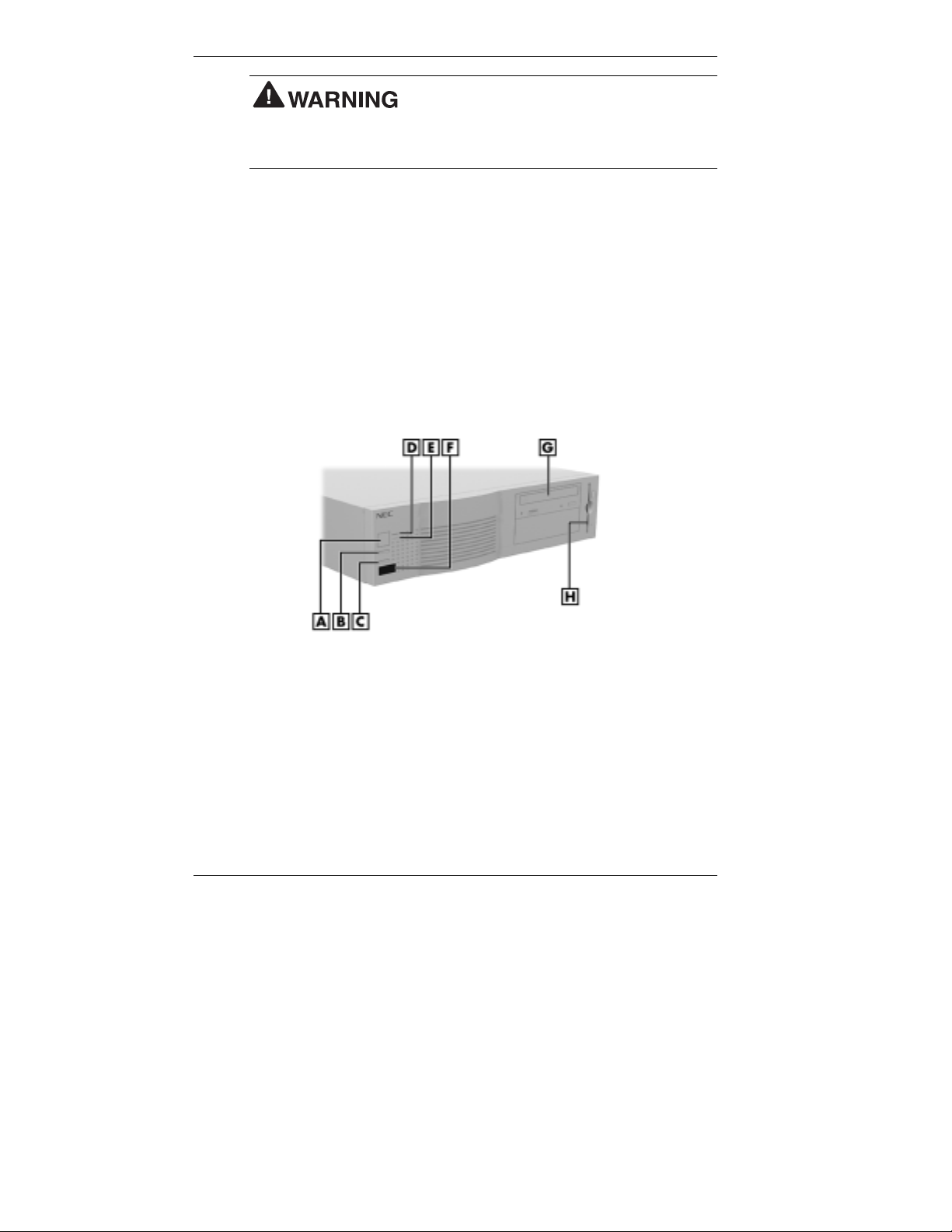
Front features - desktop models
Prolonged or improper use of a computer
A
– Power Button
B
– B - Suspend Button
C
– C - Reset Button
D
– Power Lamp
1-2 Reviewing System Features
E
– Disk Lamp
F
– IR Window
G
– CD-ROM Drive
H
– Diskette Drive

Front features - minitower models
A
– Diskette Drive
B
– CD-ROM Drive
C
– Stand
D
– IR Window
E
– Suspend Button
System Controls and Lamps
System controls let you select specific system operation s. Lamps let you
know the status of system operation. The previous figures show the
controls and lamps on the front of the system.
!
Power button
Press this button to turn on the system power. Press it again to turn off
the power.
F
– Disk Lamp
G
– Disk Lamp
H
– Reset Button
I
– Power Button
Reviewing System Features 1-3

!
Suspend button
Press this button to suspend system operation when you plan to be
away from your computer for a short time. P ress any key or move
your mouse to resume system operation at the point where you
stopped it.
An amber system unit power lamp indicates that the system is in a
power-saving mode.
If you have a VESA-complia nt monitor, your monitor also goes into a
power-saving mode.
!
Reset button
Use the reset button to restart your computer after it is powered on.
You might need to restart your system if your system power is on and
the computer is not running properly.
Resetting your system can result in the loss of
data. Press the reset button only when all other methods of restarting your
computer fail.
!
Power lamp
The power lamp indicates whether system power is on or off. It also
lets you know if the system is operating in a power-saving mode.
A steady green lamp indicates that the power is on to all system
components. An amber lamp indicates that the system is in Suspend
mode with full-power reduction.
!
Disk lamp
A lit disk lamp indicates that the hard drive is active. The green lamp
tells you that the hard drive is reading or writing data.
Do not turn off the system unless absolutely
necessary while the disk lamp is lit. To do so can damage your hard drive
or data.
1-4 Reviewing System Features

IR Window
The IR (infrared) window is the system's IR port. The IR port supports
two-way wireless communications. The interface uses infrared as the
transmission medium instead of a traditional cable.
The IR port lets you transfer files to or from portable devices such as
laptops and personal digital assistant (PDA) products using application
software supporting IrDA data transfer.
With the addition of an IrDA software package, you can transfer data at
speeds of up to 115 kilobytes per second (Kbps) and at distances up to
3 feet from the IR window.
Diskette Drive A
Use diskette drive A to copy data files to and from a diskette. You can
also use it as a bootable drive for loading and starting programs from a
diskette.
data, do not turn off the system or remove a diskette while the diskette
drive busy lamp is lit.
CD-ROM Drive
To prevent damage to your diskette drive and
Some models come with a 32X or 40X Max variable CD-ROM drive. Use
the CD-ROM drive to load and start programs from a compact disc (CD).
You can also use the CD-ROM drive to play your audio CDs.
Note
bootable CD. To enable the system to boot from the CD-ROM drive, see
“Boot Menu” in Chapter 4.
The CD-ROM drive operates at different speeds depending on whether
the CD you are using contains data or music. This allows you to get your
data faster and to see smoother animation and video.
You can boot your system from the CD-ROM drive with a
Reviewing System Features 1-5

DVD-ROM Drive
Some models come with a 5X digital video disc (DVD)-ROM drive. The
drive offers many improvements over the standard CD-ROM technology,
including superior video and audio playback, faster data access, and
greater storage capacities. The DVD-ROM drive uses DVD technology to
read DVD discs as well as standard audio and video CDs.
PC Card Adapter
If your system has a PC card adapter, you can add PC cards to the system.
A PC card is inserted into a PC card slot much as a diskette is inserted in a
diskette drive, but each type of PC card has a different function. One PC
card adapter lets you add a number of capabilities to your system with a
variety of PC cards.
Tape Backup Unit
Some systems come with a tape backup unit. If your system has a tape
backup unit, you can use it to q ui ckly back up all or part of your system's
files to a high-capacity tape cartridge. Backup software helps you tailor
the backup process to protect your files and applications. Files are
compressed during the backup process to conserve space and to speed up
the process.
Zip Drive
Some models come with a Zip® drive. Use the Zip drive to back up work,
archive old files, and transport your work. Store up to 100 MB of data on
a 3 1/2-inch Zip disk.
1-6 Reviewing System Features

Rear Features
On the back of your computer, you'll find external connectors, power
supply features, and expansion board slots. The following figures show
these features.
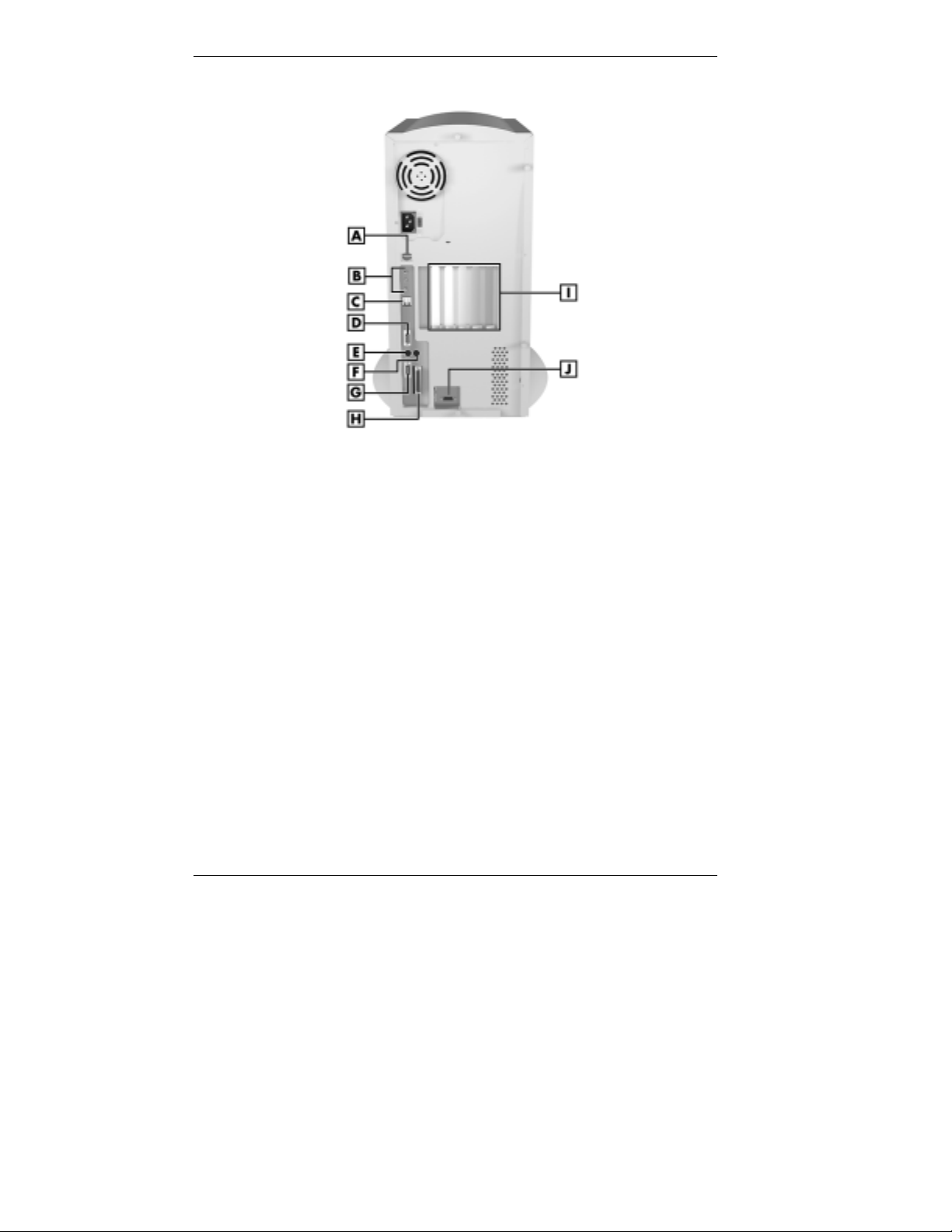
Rear features - desktop models
A
– Expansion Slots
B
– Network Board
C
– Mouse Port
D
– Printer Port
E
– VGA Monitor Connector
F
– Audio Connectors
G
– USB Ports
H
– Serial Port 2
I
– Keyboard Port
J
– Serial Port 1
Reviewing System Features 1-7
Rear features - minitower models
A
– LAN Connector
B
– Audio Connectors
C
– USB Ports
D
– Serial Port 2
E
– Keyboard Port
External Connectors
External connectors let you attach peripheral devices, such as a monitor,
keyboard, mouse, and printer to your system. Your system has the
following external connectors:
!
Mouse port
Attach the mouse that comes with your computer to this port. The
mouse port supports a PS/2-compatible mouse.
!
Keyboard port
Attach the keyboard that comes with your computer to the keyboard
port.
The keyboard port supports a personal system/2–compatible (PS/2
compatible) 101-key or 104-key keyboard (in the U.S. and Canada) or
a 102-key keyboard (in the United Kingdom and Germany) with a
6-pin mini DIN connector.
1-8 Reviewing System Features
F
– Mouse Port
G
– Serial Port
H
– Printer Port
I
– Expansion Slots
J
– VGA Monitor Connector
®
-

!
VGA monitor connector
The system comes with an AGP board connected to the system board.
The AGP board provides an external VGA connector. AGP boards
available from NECC support an NEC MultiSync
VistaScan
™
monitor, or other video graphics array (VGA)-compatible
®
monitor, NEC
monitor with a 15-pin connector. Attach the signal cable from your
monitor to the VGA connector on the AGP board.
!
Printer port
Use this port to connect a parallel printer with a 25-pin connector to
the system.
!
Serial ports (COM1 and COM2)
Attach a serial device with a 9-pin connector to each serial port. Serial
devices include a pointing device, serial printer, or a modem.
!
Audio connectors
The following connectors come integrated on the system board (see
the following figures):
— Microphone in jack
The microphone in jack lets you connect a microphone for
recording audio information in your data system files.
— Line in jack
The line in jack lets you connect a stereo audio device such as a
stereo amplifier or a cassette or minidisc player for playback or
recording.
— Line out jack
The line out jack allows you to connect an amplified output
device, such as powered speakers, a stereo tape recorder, or an
external amplifier for audio output. If you ordered speakers, use
this jack to connect them.
Reviewing System Features 1-9
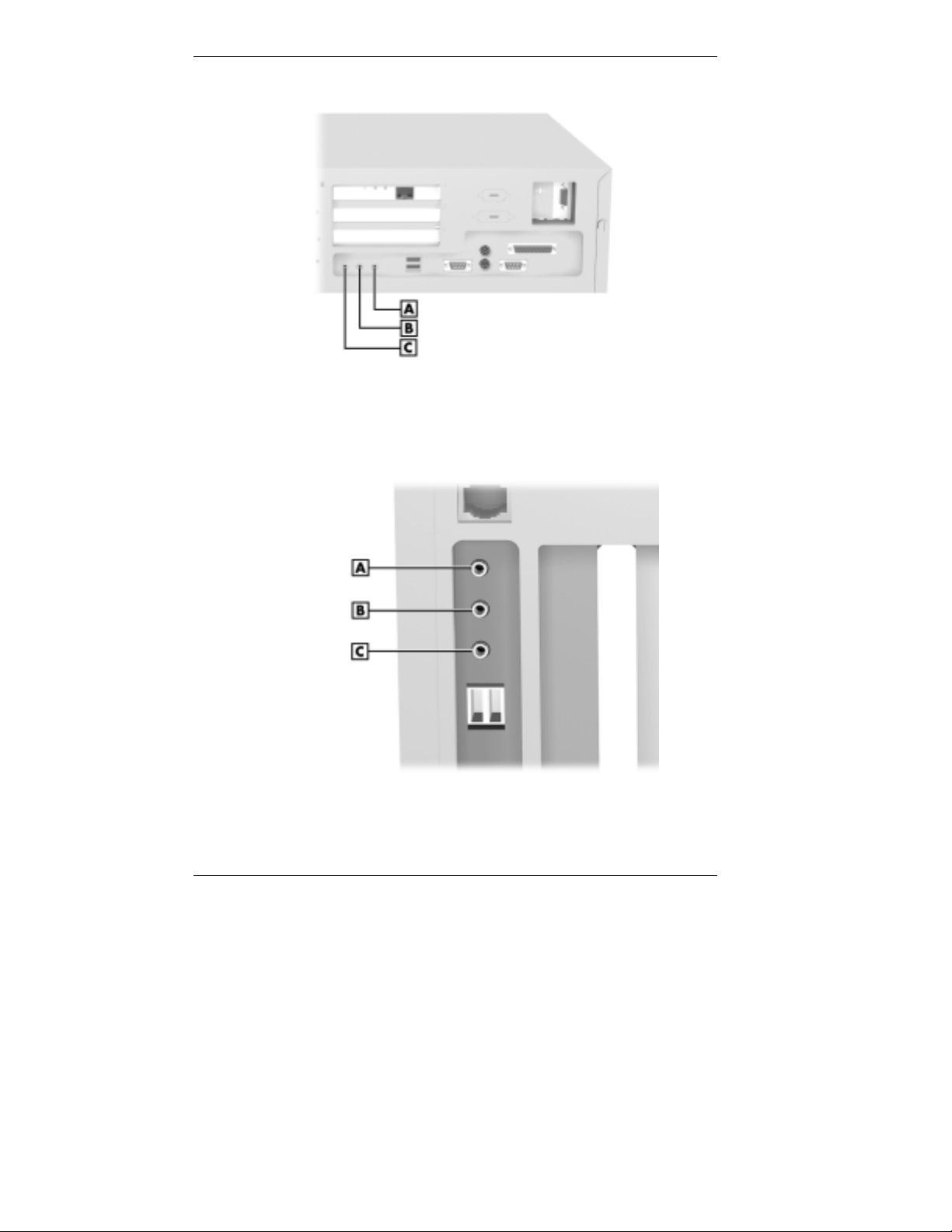
Audio connectors - desktop models
A
– Line Out Jack
B
– Microphone In jack
Audio connectors - minitower models
A
– Line In Jack
B
– Microphone In Jack
C
– Line In Jack
C
– Line Out Jack
1-10 Reviewing System Features

!
Universal Serial Bus ports
The Universal Serial Bus (USB) ports allow you to add new plug and
play serial d evices without opening up the syst em. You simply plug
the devices into the ports. The USB determines system resources for
each peripheral and assigns them without user intervention. Up to 127
devices can be daisy chained to the USB ports.
!
Fax/modem ports
Some systems come with a 56-kilobytes per second (Kbps)
fax/modem board. The fax/modem board allows the connection of a
phone line to the computer for fax and data communications functions.
Dual fax/modem ports let you use a telephone line for the fax/modem
and your telephone.
!
LAN connector
The rear panel on minitower models contains one RJ-45-compatible
port for connecting the system to an Ethernet local-area network
(LAN). Desktop models have a network board installed in a PCI slot.
!
SCSI port
Some systems come with a SCSI adapter board in an expansion slot
on the rear panel. An Ultra-Wide SCSI interface on the board allows
connection of up to 15 SCSI devices to the board.
Power Supply Features
Your system has the following power supply features:
!
Power supply fan
The power supply fan cools system components and prevents them
from overheating. Keep the area near the fan clear for proper
ventilation.
!
Voltage selector switch
Sets the voltage for your system to 115 volts or 230 volts.
Set the switch correctly for the voltage in your
area. Most wall outlets in the United States and Canada are 115 volts.
Outlets in Europe, Australia, and Asia (except Taiwan) are 230 volts.
Taiwan uses 115-volt outlets.
!
Power socket
Connect your power cable to this socket.
Reviewing System Features 1-11
Inside Features
See the following figures for the location of features within the system.
Feature descriptions follow.
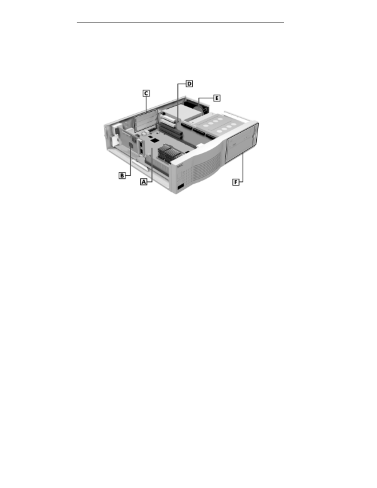
Inside the system - desktop models
A
– System Board
B
– AGP Board
C
– Expansion Slots
1-12 Reviewing System Features
D
– Riser Board
E
– Internal Device Slot
F
– Accessible Device Slots
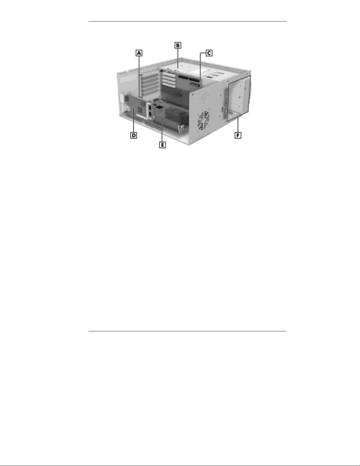
Inside the system - minitower models
A
– Expansion Slots
B
– Internal Device Slots
C
– Riser Board
System Board
System memory, the processor, the AGP board, and the system battery
reside on the system board. The system board also comes with an audio
subsystem.
External connectors include two serial connectors, a parallel connector,
two USB ports, keyboard and mouse ports, and external audio connectors.
For information on these connectors, see “External Connectors” earlier in
this chapter.
The system board supports a diskette drive and up to four IDE devices
such as IDE hard drives, an IDE CD-ROM drive, an IDE DVD-ROM
drive, or an IDE Zip drive.
D
– AGP Board
E
– System Board
F
– Accessible Device Slots
Reviewing System Features 1-13

Riser Board
Most of the cable connectors in the system reside on the riser board. Riser
board connectors include:
!
primary and secondary IDE connectors
!
diskette drive connector
!
front panel connector for lamp and infrared signals
!
the NLX connector for the system board
!
additional connectors including the CD Audio In, Modem In, WakeOn LAN connector, the minitower chassis intrusion connector
(hardware monitor), speaker connector (minitower models), and fan
connector (minitower models)
!
the external LAN connector (minitower models)
!
power connectors (on the back of the board)
Expansion board connectors on the riser board are as follows:
Desktop models
!
one PCI connector
!
one shared PCI/ISA connector
!
one ISA connector
Minitower models
!
three PCI connectors
!
one shared PCI/ISA connector
!
one ISA connector.
AGP Board
The system board supports the AGP (Accelerated Graphics Port)
standard. All models come with an AGP board.
AGP boards enhance graphics performance, particularl y for 3-D
applications.
1-14 Reviewing System Features

Network Board
Desktop models ship with a 3Com® network board installed in a PCI slot.
This board is a 10/100Base-T Ethernet board.
Storage Device Support
In desktop models, four storage device slots accommodate up to three
accessible devices and one internal hard drive. In minitower models, six
storage device slots accommodate up to four accessible devices and two
internal hard drives.
Intellicase Chassis
The NEC Intellicase chassis conforms to the NLX form factor. With the
NLX form factor, the system has the following features:
!
standardized chassis size and dimensions
!
standardized system board size and dimensions
!
riser board with an NLX connector for signal and power circuitry to
keep the system board largely free of cabling
!
a system board that installs along rails with a single securing latc h for
easy access.
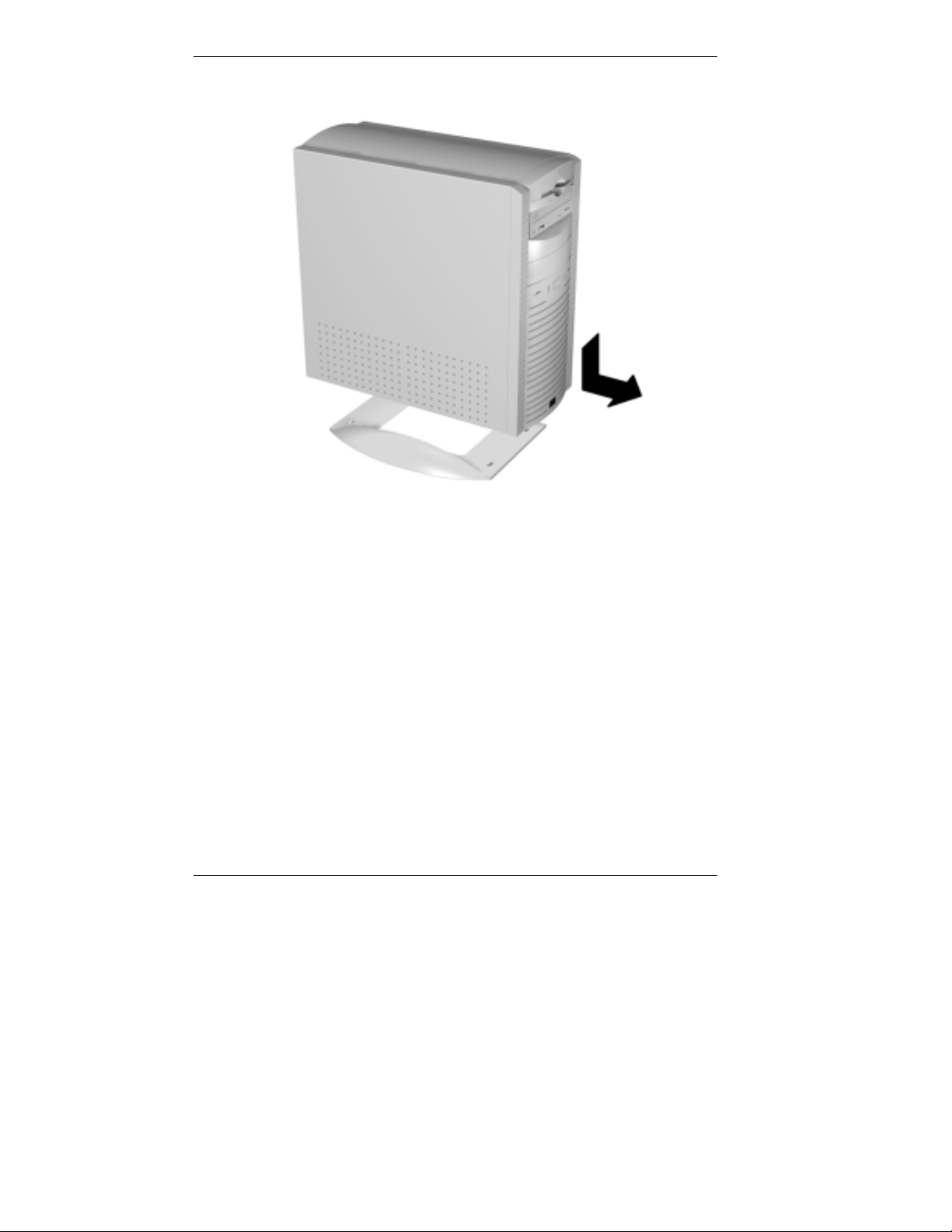
Stand
The minitower system unit sits on a stand to p r event it from being tipped
over. This is a safety feature to prevent personal injury and equipment
damage. Keep the system unit in the stand except when opening or
upgrading the system.
Place the system unit on the stand so the stand's tabs go into the slots in
the bottom of the chassis. Slide the system unit forward to lock the tabs in
the slots.
designed to keep the unit from being tipped over.
Keep the system unit in the stand. The stand is
Reviewing System Features 1-15
Speakers
Minitower chassis stand
Some systems come with a pair of high-quality stereo speakers that you
can arrange to suit your work environment.
An AC adapter comes with the speakers if you ordered speakers. Set up
the speakers with the AC adapter.
Adjust the speaker volume by using the volume control on the front of the
right speaker or by using the Windows sound software. To bring up a
volume control, double click the speaker icon on the taskbar (next to the
system clock). Also use the software to balance the sound between the left
and right speakers.
1-16 Reviewing System Features

System Features
Your computer hardware and software deliver the performance and
technologies you need for all your challenging tasks toda y and into the
future.
Hardware
The PowerMate 8100 Series includes the following hardware features:
!
PC98 Compliance
All the hardware in the system has been certified by Microsoft
PC98 compliant.
!
Latest in Processor Technology
The system comes with a Celeron
Pentium III processor. Some of these are fast, powerful processors that
lend themselves to heavy-duty computational, graphical, and
networking t asks.
!
Audio on the System Board
The system board comes with an audio subsystem. The audio chipset
gives you a s urround sound system for three-dimensional sound
effects - much like a live performance! It also provides wavetable
synthesis. (Wavetable synthesis uses actual recordings of real sound
effects and musical instruments for a dynamic audio experience.)
™
, Intel Pentium® II, or Intel
®
to be
!
Sound Board
Some systems come with the Creative
®
Labs Sound Blaster® Live!
board. This board produces superb three-dimensional sound with
multiple voices. The board is upgradeable so you enhance your board
with Creative Lab’s latest innovations.
!
Flashable ROM BIOS
The system's ROM BIOS features system setup configuration, Plug
and Play support, and flash support for easy and economical BIOS
upgrades.
!
System Memory
Your computer comes with at least 32 MB of SDRAM and supports
up to 384 MB. The system also provides ECC memory support.
The system memory is made up of Dual In-Line Memory Module
(DIMM) sticks. DIMMs have 168 pins and are non-parity.
Reviewing System Features 1-17
™
 Loading...