


Proprietary Notice and Liability Disclaimer
The information disclosed in this document, including all designs and
related materials, is the valuable property of NEC Computer Systems
Division, Packard Bell NEC, Inc. (hereinafter “NEC CSD”) and/or its
lice nsor s . NEC CSD and/ or its li cens or s, as app rop ria t e, r eser ve a ll p at ent,
copyright and other proprietary rights to this document, including all
desi g n, manu fa c tu r in g, r epr oducti on, u s e, a nd s a l es r i ghts t hereto, ex c ep t to
the ex tent said r ights are express ly gra nted to others .
The NEC CSD product(s) discussed in this document are warranted in
accordanc e with the terms of the Warr anty Statement accompan ying each
product. However, actual performance of each such product is dependent
upon factors such as system configuration, customer data, and operator
contr o l. S ince imp leme nta t ion b y cus to mers of each pr oduc t may var y, th e
suitability of specific product configurations and applications must be
determined by the customer and is not warranted by NEC CSD.
To allow for design and specification improvements, the information in this
document is subject to change at any time, without notice. Reproduction of
this document or portions thereof without prior written approval of
NEC C SD is pr ohibit e d.
As an ENERGY STAR partner, NEC Computer Systems Division (NEC CSD) has
determined that this product meets the ENERGY STAR guidelines for energy
efficiency.
FaxFlash is a service mark and WebTelligent is a trademark of NEC Computer Systems
Division , Packar d B e ll NEC, In c.
NEC and PowerMate are registered trademarks of NEC Corporation, used under license.
ENERGY STAR is a U.S. registered trademark.
All other product, brand, or trade names used in this publication are the trademarks or
registere d t rademarks of th eir respe ct ive trademark ow ners.
First Printing — July 1998
Copyright 1998
NEC Computer Systems Division
Packar d Bell NEC, Inc.
1 Packar d Bell Wa y
Sacramento, CA 95828-0903
All Rights Reserved

Using This Guide
The PowerMate 5100 Series User’s Guide provides a
comprehensive reference to infor mat ion about your
computer.
The guide contains the following informat ion:
Chapter 1, Reviewing System Featur es, provides a look at
the front, rear, internal, and periphera l featur es of the
syste m. It also gives a summary of the system’s hardware
and software, and secur ity features.
The chapter includes a quick-reference chart for finding
information described more fully later in the document.
Chapter 2, Setting Up the System, explains how to set up,
start up, and shut down the syste m. It also pro v ides
information on installing applications and tips on caring
for the system.
Chapter 3, Configuring the System, describes how to use
the software utilities shipped with your system, including
the BIOS Setup Utility, the NEC Select Install CD, and the
NEC Driver CD. It also pro vides detailed infor mat ion on
jump e ring d evices in t he system.
Chapter 4, Managing System Reso u r ces, describes the
utilities t hat al low you to identify and control system and
networked reso urces. S ee th is chapter for infor mat ion
about LANDesk® Client M anage r, NEC WebTelligent,
the NEC SNMP Agent, the Cheyenne backup utility, and
NEC Security.
Chapter 5, Installing Options, provides detailed
installation proce dures for int ernal o ption s .
Using This Guide ix

Chap ter 6, Solving System Proble ms , co ntains
troubleshooting tips fo r solving si mple proble ms a nd
describes how to find help when you cannot solve a
problem yourself.
Chapter 7, Getting Services and Support, describes the
services avai lable t o you for info rmation and help, and
describes how to access the services.
Appendix A, Setting Up a Healthy Work Environment,
contains guidelines to help you use your computer
productively and safely. This appendix also instructs you
on how to set up and use your computer to reduce your
risk of developing nerve, muscle, or tendon disorders.
!
WARNING
Prolonged or improper use of a c om puter
workstation may pose a risk of serious injury. To
reduce your risk of i njur y, set up and use your
computer as described i n A ppendix A , Sett ing Up
a Healthy Work Environment.
Appendix B, System Specifications, provides a technical
description of your computer and its components.
Appendix C, Qu estions and Answers, provides answers to
questions frequently asked about the system.
x Using This Guide
Text Conventions
This guide u ses t he following text convent ions.
Warnings, caut ions, and notes have the following
meanings:
!
WARNING
Warnings alert you to situations that could result
in serious personal injury or loss of life.
!
CAUTION
Cautions indi c ate situations that can damage the
hardware or software.
Note:
about the material being described.
Names of keyboard keys are printed as they appear on the
keyboard, for example,
Text or keystrokes that you enter appear in boldface type.
For example, type
File names are printed in uppercase letters. For example,
Notes give important information
Ctrl, Alt
abc123
and press
, or
Enter
Enter
.
.
AUTOEXEC.BAT.
Using This Guide xi

Related Documents
In addition to this guide, the following printed documentation
ships with your computer.
NEC PowerMate 5100 Series Quick Setup/Quick
Reference
The Quick Setup shows how to quickly get the system
connected and powered on.
The Quick Reference briefly descr ibes t he do cumentat ion,
NEC CSD tools and utilities, software applications, and
services availa ble w ith the NEC PowerMate® 5100 Series
computer.
How Does Your Workplace Measure Up?
This brochure provides information for setting up and
using the computer productively and safely. Informat ion
includes guidelines to reduce the risk of injury associated
with using a computer.
NEC PowerMate 5100 Series Release Notes
Release Not es pro vide addit ional information about the
computer that was not available at t he time the user’s
guide was printed.
NEC PowerMate Series Installing Your Applications
Fo llow the directions in this brief docu ment to install
applications and the NEC He lp Center on your syst em
from the NEC Select I nst all CD.
xii Using This Guide

Your system comes with the following online documentation
on the NEC Select Inst all CD:
NEC Help Center
The NEC Help Center is an online version o f the pr inted
user’s guide. It pro vides infor mation about your system
under the following to pics: System Tour, System
Information, S ystem Upgrades, FAQs, and Service &
Support.
Healthy Environment
This is an online h elp file that c omple ments the “How
Does Your Workplace Measure Up?” brochure.
In addition to the documentation that ships with t he syst em,
the following documentat ion is available fro m NEC CSD:
NEC PowerMate 5100 Series Service and Reference
Manual (part number 819-181926-000)
This manu al prov id es in fo r m ation fo r maint a in in g ,
troubleshooting, and repairing the computer. This manual
also includes hardware a nd interface information for
programmers, engineers, and others who need to know
how the system is designed.
To purchase the service and reference manual, call NEC
CSD at
1-800-632-4525
(in the U.S. and Canada) or your
local NEC CSD sales provider (outside the U.S. and
Canada).
NEC CSD FaxFlash
SM
NEC CSD FaxFlash is an automated service that sends the
latest information about NEC CSD and its products
directly to a fax machine. The service is available 24 hours
a day, 7 days a week.
Using This Guide xiii

Obtain product literature and technical information
bulletins with FaxFlash. By using FaxFlash, you can be
kept up-to-date on the latest technical information for your
system.
See “NEC CSD FaxFlash Service” in Chapter 7 for
information about using FaxFlash.
xiv Using This Guide

Contents
Using This Guide
Text Conventions .............................................................................xi
Related Documents.........................................................................xii
1 Reviewing System Features
Front Features............................................................................... 1-2
System Controls and Lamps ..................................................1-4
Diskette Drive A.................................................................... 1-5
CD-ROM Drive..................................................................... 1-6
Rear Features................................................................................ 1- 6
External Connectors.............................................................. 1-7
Power Supply Features.........................................................1-10
Inside Features.............................................................................1-11
System Board .......................................................................1-12
Riser Board..........................................................................1-13
Power Supply.......................................................................1-13
IntelliCase Chassis...............................................................1-14
Speakers......................................................................................1-14
System Features...........................................................................1-16
Hardware..............................................................................1-16
Software...............................................................................1-18
Preloaded Operating System.........................................1-18
NEC Select Install CD..................................................1-18
NEC Driver CD............................................................1-20
Security................................................................................1-21
2 Setting Up the System
Cable Connections........................................................................ 2-2
Startup.......................................................................................... 2-4
Shutdown...................................................................................... 2-5
Power-Saving Features.................................................................. 2-7
System Care.................................................................................. 2-7
Protecting the System From Damage..................................... 2-8
Keeping the System in Good Condition................................. 2-9
Contents iii

Moving or Shipping the System............................................2-10
More Information.........................................................................2-11
3 Configuring the System
Configuration Tools and Utilities.................................................. 3-2
BIOS Setup Utility........................................................................ 3-5
How to Start BIOS Setup....................................................... 3-5
How to Use BIOS Setup........................................................ 3-6
Maintenance Menu................................................................ 3-7
Main Menu............................................................................ 3-8
Advanced Menu...................................................................3-10
Security Menu ......................................................................3-19
Power Menu.........................................................................3-21
Boot Menu...........................................................................3-23
Exit Menu............................................................................3-25
FLASH Utility.............................................................................3-25
NEC Select Install CD.................................................................3-26
Introducing Select Install Options.........................................3-27
Choosing a Program.............................................................3-28
Rebuilding the Hard Drive and Restoring the Operating
System...............................................................................3-29
Auto Rebuild and Restore.............................................3-30
Custom Rebuild and Restore .........................................3-34
Restoring the Operating System............................................3-39
Installing Applications..........................................................3-43
Using the Selective Appli catio n Rest ore Progra m
on a Remote CD................................................................3-45
NEC Help Center.........................................................................3-48
Installing the NEC Help Center ............................................3-48
Uninstalling the NEC Help Center........................................3-49
NEC Driver CD...........................................................................3-49
Installing Drivers with the NEC Driver CD...........................3-50
Installing Drivers from a Remote CD....................................3-51
iv Contents

Jumper Settings............................................................................3-54
System Board Jumper Settings..............................................3-54
Verifying the Processor Speed.......................................3-56
Clearing a Password......................................................3-59
Hard Drive Jumper Settings..................................................3-61
NEC 32X CD-ROM Drive....................................................3-62
4 Managing System Resources
System Management Tools........................................................... 4-2
LANDesk Client Manager............................................................. 4-4
PC Health Indicator............................................................... 4-6
Managing Workstations................................................. 4-6
Selecting the PC Health Meter ....................................... 4-6
Monitoring PC Health.................................................... 4-7
Inventory............................................................................... 4-7
DMI...................................................................................... 4-8
Monitoring Capa bilities ......................................................... 4-9
Using the Chassis Intrusion Notification Feature...........4-10
LDCM Admin Function .......................................................4-11
Cheyenne Backup........................................................................4-11
NEC Security...............................................................................4-12
NEC SNMP Agent.......................................................................4-12
Installing the NEC SNMP Agent..........................................4-14
Configuring the NEC SNMP Agent for Windows 95............4-14
Configuring the NEC SNMP Agent for Windows 98............4-16
Configuring the NEC SNMP Agent for Windows NT ...........4-18
NEC WebTelligent.......................................................................4-19
NEC WebTelligent Features.................................................4-20
NEC WebTelligent Requirements.........................................4-22
NEC WebTelligent Installation.............................................4-23
NEC Configuration Change Notification......................................4-28
NEC Auto Backup Utility............................................................4-29
5 Installing Options
General Rules............................................................................... 5-2
Safety Precautions......................................................................... 5-2
Contents v

System Unit Cover ........................................................................ 5-4
Removing the Cover.............................................................. 5-4
Replacing the Cover.............................................................. 5-7
System Board Removal and Replacement ..................................... 5-9
System Board Removal......................................................... 5-9
System Board Replacement..................................................5-11
DIMM Upgrade...........................................................................5-15
Checking System Memory....................................................5-17
Removing a DIMM..............................................................5-17
Installing a DIMM................................................................5-19
Expansion Boards........................................................................5-21
Locating Expansion Slots.....................................................5-21
Installing an Expansion Board..............................................5-23
Removing an Expansion Board.............................................5-26
Data Storage Devices...................................................................5-27
Locating Device Slots...........................................................5-28
Preparing the Device ............................................................5-28
Connecting Device Cables....................................................5-29
Diskette Drive Signal Cable..........................................5-31
IDE Signal Cables.........................................................5-32
System Power Cables....................................................5-33
Cabling Storage Devices.......................................................5-34
IDE Device Cabling......................................................5-35
Diskette Drive Cabling..................................................5-36
Installing Storage Devices ....................................................5-37
Removing the Front Panel....................................................5-38
Replacing the Front Panel.....................................................5-40
Installing a 5 1/4-Inch Device...............................................5-42
Installing a 3 1/2-Inch Hard Drive.........................................5-44
6 Solving System Problems
Solutions to Common Problems.................................................... 6-2
System Problems................................................................... 6-2
Diskette Drive Problems........................................................ 6-4
Monitor Problems.................................................................. 6-5
Keyboard/Mouse Problems.................................................... 6-6
CD-ROM Drive Problems..................................................... 6-7
Speaker Problems.................................................................. 6-8
vi C ont ents

How to Clean the Mouse ............................................................... 6-8
Battery Replacement....................................................................6-10
How to Get Help..........................................................................6-13
Getting Help From Your Company.......................................6-14
Getting Help From an NEC CSD Dealer...............................6-14
Getting Help From NEC CSD Technical Support Center ......6-14
NEC CSD Warranty/Non-Warranty Repair Service..............6-15
7 Getting Services and Support
NEC CSD Website........................................................................ 7-2
NEC CSD FTP Site.......................................................................7-3
NEC CSD FaxFlash Service.......................................................... 7-3
Email/Fax Technical Support Service............................................ 7-5
NEC CSD Bulletin Board System................................................. 7-6
NEC CSD Technical Support Services.......................................... 7-9
A Setting Up a Healthy Work Environment
Making Your Computer Work for You.........................................A-2
Arrange Your Equipment.............................................................. A-4
Adjust Your Chair.........................................................................A-5
Adjust Your Input Devices............................................................A-7
Adjust Your Monitor.....................................................................A-9
Vary Your Workday....................................................................A-11
Pre-existing Conditions and Psychosocial Factors.......................A-12
Checking Your Comfort: How Do You Measure Up?.................. A-13
Checking Your Chair...........................................................A-13
Checking Your Keyboard....................................................A-13
Checking Your Mouse.........................................................A-13
Checking Your Monitor.......................................................A-13
Checking You .....................................................................A-14
B System Specifications
System Processor..........................................................................B-2
Processor Support.................................................................. B-2
Processor Socket ...................................................................B-2
Random Access Memory (RAM)..................................................B-2
Read Only Memory (ROM)..........................................................B-3
Content s vii

Calendar Clock.............................................................................B-3
Input/Output (I/O) Facilities..........................................................B-3
Sound System...............................................................................B-5
Fax/Modem Board........................................................................B-5
Graphics.......................................................................................B-6
Diskette Drive...............................................................................B-6
Hard Drive....................................................................................B-7
CD-ROM Drive............................................................................B-8
PC Card Adapter...........................................................................B-8
Video Board.................................................................................B-8
Speakers.......................................................................................B-8
Dimensions ...................................................................................B-9
System Unit........................................................................... B-9
Keyboard...............................................................................B-9
Power ...........................................................................................B-9
Operating Environment...............................................................B-10
Compliance.................................................................................B-10
C Questions and Answers
Boot Questions.............................................................................C-2
BIOS Questions............................................................................C-4
Monitor Questions........................................................................C-6
Multimedia Questions ...................................................................C-7
CD-ROM Drive Questions............................................................C-9
Mouse Questions ..........................................................................C-9
Power Management Questions.................................................... C-11
System Security Questions..........................................................C-12
Memory Questions......................................................................C-14
Modem Questions.......................................................................C-14
Miscellaneous Questions.............................................................C-15
Glossary
Index
viii Contents

Reviewing System Features
Front Features
Rear Features
Inside Features
Speakers
System Features
1

!
WARNING
Prolonged or improper use of a c om puter
workstation may pose a risk of serious injury. To
reduce your risk of i njur y, set up and use your
computer as described i n A ppendix A , Sett ing Up
a Healthy Work Environment.
The PowerMate® 5100 Series system features the latest in
component technology, including support for both the Intel
Cele ron™ a nd Pentium® II 266-MHz, 300-MHz, or
333-MHz processors and built-in Accelerated Graphics Port
(AGP) functionality. These co mponents are ho used inside the
system’s space-saving, mini-desktop chassis.
This chapter provides a look at the front, rear, internal, and
peripheral features of the system. It highlights syste m
hardware and software, and descr ibes the security features of
the system.
For more information abou t using system features, see
Chapter 3, “Configuring the System” and Chapter 4,
“Managing Syst em Resources.” See the NEC Help Center for
a comprehensive source of online information about your
Power Mat e system.
Front Features
The following figures show the features on the front of the
syste m. A brie f de scription fo llow s the figures.
®
1-2 Reviewing System Features
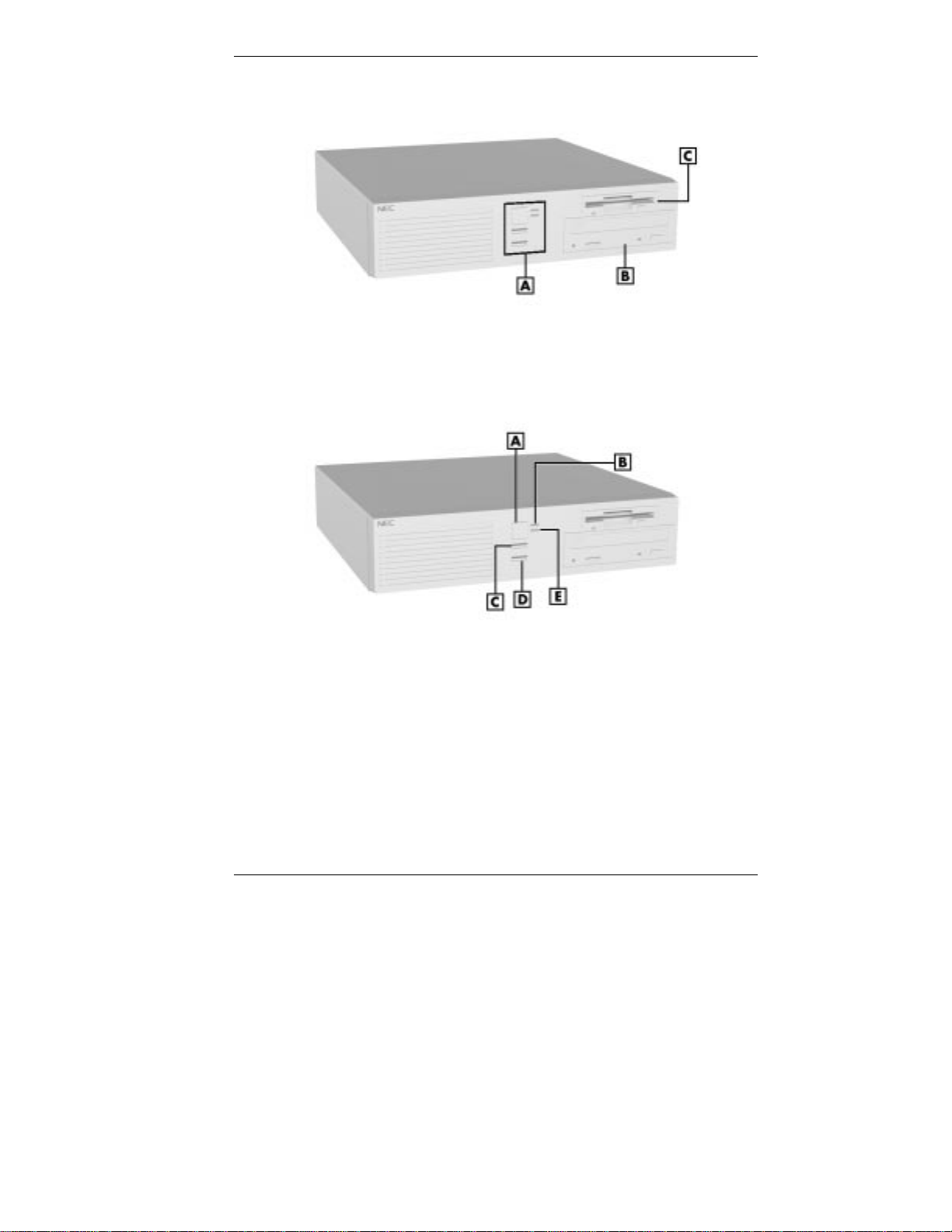
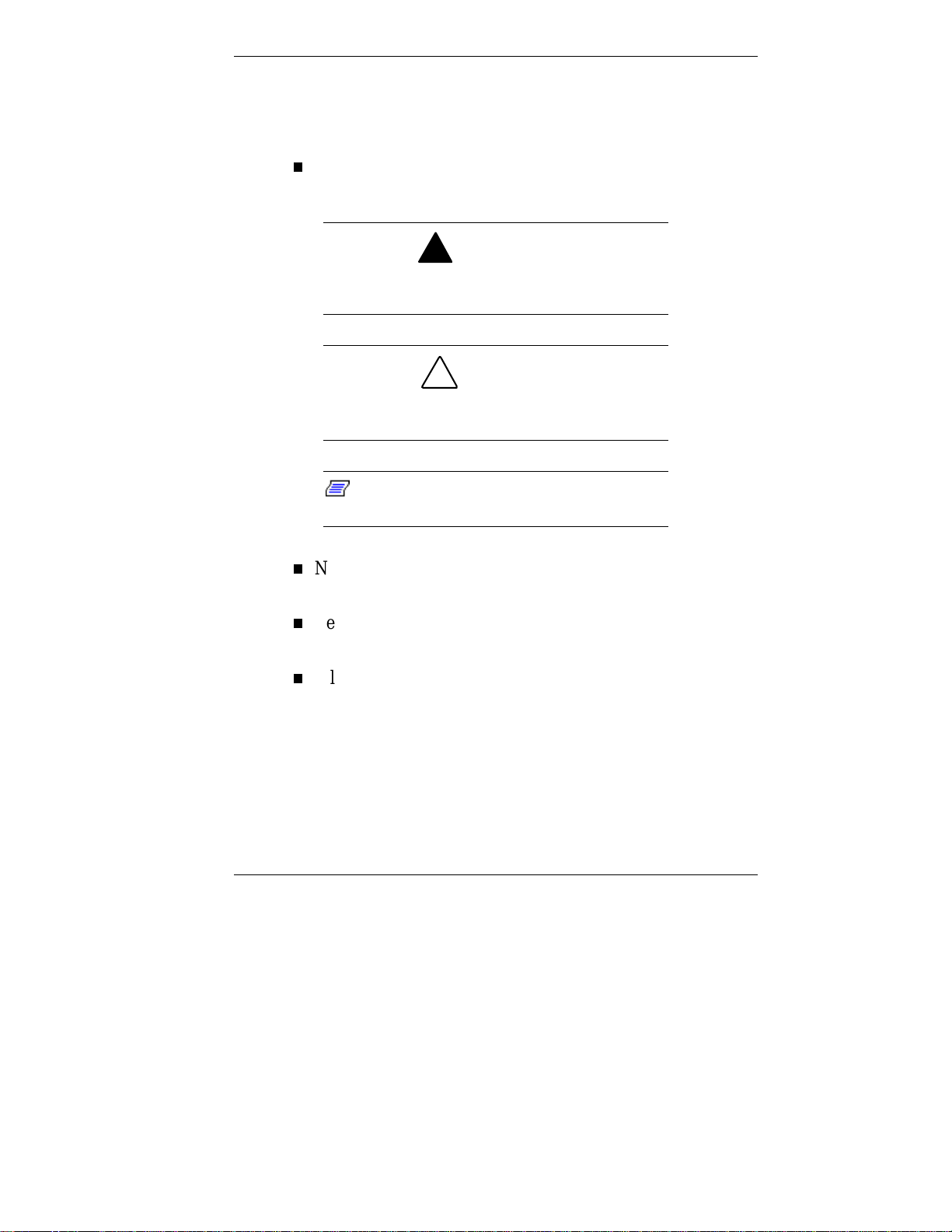
Front features
A – System Controls and Lamps
B – CD-ROM Drive (not installed in all systems)
C – Dis kette Drive ( not ins talled in all syst ems)
System co ntr ols an d lamps
A – Power Button B – Power Lamp C – Suspend Button
D – Reset Button E – Disk Lamp
Reviewing System Features 1-3

System Controls and Lamps
System contro ls let you se lect specific system operat ions.
Lamps let you know the status of system operation. The
computer has the fo llowing contr ols and lamps:
Power button
Press this button to turn on the system power. Press it
again to turn off the power.
Suspend button
Press th is but t on to suspend system operation when you
plan to be away from the computer for a short t ime. Press
any key or move the mouse to resume system operation at
the point where you stopped it.
An amber system unit power lamp indicates that the
system is in a power-saving mode.
If you have a VESA-compliant monitor, t he monitor also
goes into a power-saving mode.
Reset button
Use the reset button to restart the computer after it is
powered on. You might need to restart the computer if the
system power is on and the computer is not running
properly.
!
CAUTION
Resetting your system can result in the loss of
data. Press the reset butt on only when all other
methods of restarting the computer fail.
1-4 Reviewing System Features

Power lamp
The power lamp indicates whether syst em power is on or
off. It also lets you know if the system is operating in a
power-saving mode.
A steady green lamp indicates that the power is on to all
system components. An amber lamp indicates that the
system is in Suspend mode with full-power reduction.
Disk la mp
A lit disk lamp indicates t hat the hard drive is act ive. The
green lamp tells you that the hard drive is reading or
writing data.
Do not turn off the system unless absolutely
necessary while the disk lamp is lit. To do so can
damage your hard driv e or data.
Diskette Drive A
!
CAUTION
Some systems come with a 3 1/2-inch diskette drive
(assigned as drive A by the syste m). Use diskette drive A to
copy data files to and from a diskett e. You can also use it as a
bootable drive for loading and starting programs from a
diskette.
!
CAUTION
To prevent damage to the disket te drive and
data, do not turn off the system or remove a
diskette whil e the diskette drive busy lamp is lit.
Reviewing System Features 1-5

CD-ROM Drive
Some systems come with a 32X Max variable CD-ROM
drive. Use the CD-ROM drive to load and start prog r ams
from a compact disc (CD). Yo u can also use the CD-ROM
drive to play audio CDs.
Note:
CD-ROM drive with a bootable CD. To enable
the system to boot from the CD-RO M drive, see
“Boot Menu” in Chapter 4.
The CD-ROM drive operates at different speeds depending
on whether the CD you are using contains data or music. This
allows you to get your data faster and to see smoother
animation and video.
You can boot the system from the
Rear Features
On the back of the computer, you can find external
connectors, power supply features, and expansion board slots.
1-6 Reviewing System Features
The following figure shows these features.
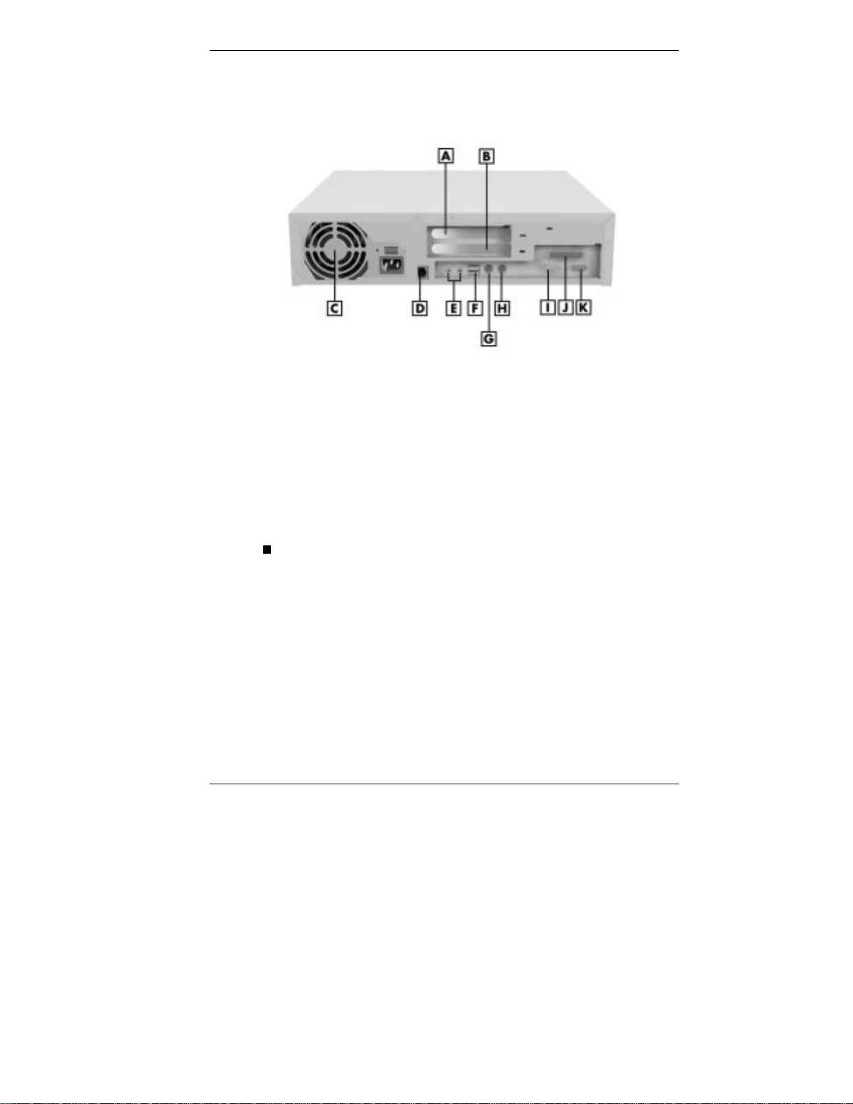
A – Shared PCI/ISA Slot B – PCI Slot C – Power Supply Fan
D – LAN Connector E – Audio Connectors F – USB Connectors
G – Mouse Port H – Keyboard Port I – Serial Port
J – Parallel Port K – VGA Connector
External Connectors
External connector s let you attach peripheral devices (such as
a monitor, keyboard, mouse, and printer) to the system. The
computer has the following external connect or s:
Rear features
VGA connector
Attach the signal cable from the monitor to the VGA
connector. T he VGA connector and the system board
AGP controller provide enhanced grap hics per forma nce,
particularly for 3-D applications. The VGA connector
supports an NEC MultiSync® monitor or other video
graphics array (VGA)-compatible monitor with a 15-pin
connector.
Reviewing System Features 1-7
Audio connectors
The following connector s co me integrated on the system
board (see the following figure):
Microphone in jack
The microphone in jack lets you connect a microphone
for recording audio information in your data s ystem
files.
Line out jack
The line out jack allows you to connect an amplified
output device, such as powered speaker s, a stereo tape
recorder, or an external amplifier for audio output. If
you ordered speakers, use t his jack to connect t hem.
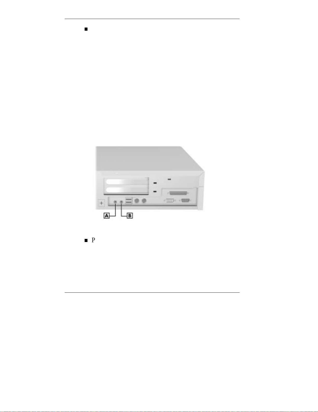
Audio connectors
A
– Microphone In Jack B – Line Out Jack
Printer port
Use this port to connect a parallel printer with a 25-pin
connector to the system.
1-8 Reviewing System Features

Serial port (COM1)
Attach a serial device with a 9-pin connector to the ser ial
port. Serial devices include a pointing device, serial
printer, or a modem.
Keyboard port
Attach the keyboard that comes with the co mputer t o t he
ke yboard port.
The keyboard port supports a personal system (PS)/2®compatible, 101-key or 104-key keyboard (in the U.S. and
Canada) or a 102-key keyboard (in the United Kingdom
and Germany) with a 6-pin mini DIN connector.
Mouse port
Attach the mouse that co mes w ith the co mputer to this
port. The mouse port supports a PS/2-compatible mouse.
Unive rsal Se rial Bus ports
The Universal Serial Bus (USB) ports allow you to add
new plug and play serial devices without opening up the
system. You simply plug the devices into the ports. The
USB determines syst em resources for each periphera l and
assigns them without user intervention. Up to 127 devices
can be daisy chained to the USB ports.
LAN connector
The rear panel contains one RJ-45-compatible port for
connecting the syste m to an Ethernet local-area network
(LAN) so you can communicate with other computers.
Fa x /mo d em board
You can order a 56-kilobytes per second (Kbps)
fax/modem board and install it in an expansion slot ( see
Chapter 5 for option installation procedures). The
fax/modem board allows the connect ion o f a phone line to
the computer for fax and data communications functions.
Reviewing System Features 1-9

Dual fax/modem ports let you use a telephone line for the
fax/modem and your telephone.
Networ k board
You can order a network board from NEC CSD and install
it in an exp ansion slot (se e Chapter 5 for option
installation procedures). This board allows you to
configure your system to meet varying network interface
requirements.
PCI Video Board
You can order a video board from NEC CSD and install it
in an expansion slot (see Chapter 5 for opt ion inst allation
procedures). This board is compat ible with the PCI
graphics standard and supports graphics-intensive, 3-D
applications.
Power Supply Features
The system has the following power supply features:
Pow er supply fan
The power supply fan cools system components and
prevents them from overheat ing. Keep the area near t he
fan clear for proper vent ilation.
Voltage selector switch
Sets the voltage for the system to 115 volts or 230 volts.
!
CAUTION
Set the switch corr ectly for the voltage in your
area. Most wall outl ets in the United States and
Canada are 115 volts. O utlets in Europe,
Australia, and Asi a ( ex c ept T aiwan) are 230
volts. Taiwan uses 115-v olt outlets.
1-10 Reviewing System Features
Power socket
Connect your power cable to this socket .
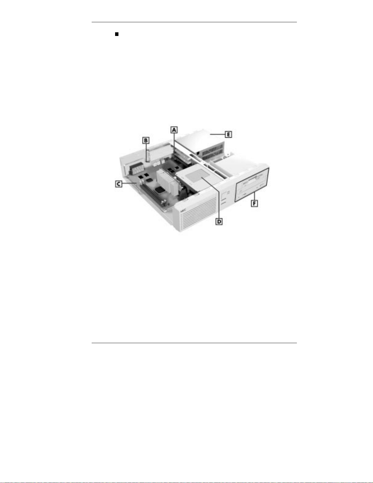
Inside Features
See the following figure for the location of features inside the
system. A list of features and feature descr ipt ions follow the
figure.
Inside the system
A
– Riser Board B – Expansion Slots C – System Board
D
– Internal Hard Drive E – Power Supply
F
– Accessible Device Slots
Reviewing System Features 1-11

System Board
System board components include the Celeron or Pentium II
processo r, syste m memory, AGP controller, and t he syst em
battery. The syst em board a lso comes with an audio
subsystem.
External connector s include one ser ial connector, a parallel
connector, two USB port s, keyboard and mouse ports, and
external audio co nnectors. For informat ion on these
connectors, see “External Connectors” later in this chapter .
The system board supports a 1.44-MB diskette drive and an
internal IDE hard drive. The system board also supports an
IDE CD-ROM drive housed in the accessible 5 1/4-inc h
device slot. The internal hard disk can be upgraded with a
hard disk option available from NEC CSD.
Note:
drive or tape backup unit ) c an be installed in the
accessible devic e sl ot(s). These devices (and the
required cabl es) may be purchased separat ely
from your computer vendor.
See the printed release notes that shi p with the
PowerMate 5100 Series computer for up-to-date
informati on about opt ional hardware available
from NEC CSD.
Other storage devices (such as a Zi p
The system board is seated in the NLX connect or on the riser
board. The system board is installed in the chassis along
guide rails and is secured with a single latch for easy removal
and replacement.
1-12 Reviewing System Features
®

Riser Board
The riser board cont ains most of the cable connectors in the
system. The following connectors reside on the riser board:
primary and secondary IDE co nnectors
diskette dr ive connectors
expansion board connectors
front panel connector for lamps
the NLX connector for the syst em board
additional connectors including the CD Audio In, Modem
In, Wake-On LAN connector, and the chassis intrusio n
connector (hardware monitor)
the external LAN connector
power connector s (on the back of the board).
The following conn ectors support one or two expansion
boards:
one PCI connector
one shared PCI/ISA connector .
Power Supply
The system’s 145-watt power supply converts AC voltage
from the power source (such as a standard, proper ly grounded
wall outlet or power strip) to the DC voltages required for t he
system devices. For more information, see “Power Supply
Features” earlier in this chapter .
Reviewing System Features 1-13

IntelliCase Chassis
The NEC IntelliCase chass is co nforms to the NLX form
factor. With an NLX form factor , the syst em has the
following features:
standardized chassis size a nd dimens ions
standardized system board size and dimensions
riser board with an NLX connector for signal and power
circuitry to keep the syste m board largely free of cabling
a system board that ins talls along rails with a sing le
securing latch for easy access.
Speakers
Some systems come with a pair of high-quality, 9-watt stereo
speakers that you can arrange to suit your work environment.
1-14 Reviewing System Features
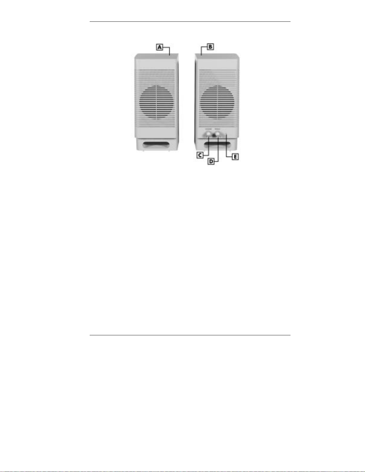
Speakers
A – Left Speaker B – Right S peaker C – Volume C ontro l
D – Treble Control E – Power Lamp
An AC adapter comes with the syste m. Set up the speakers
with the AC adapter. The speakers connect to the line out
jack on the back of the system unit.
The speaker set features a power button, a power lamp, and
volume and t reble control knobs.
Adjust the speaker volume by using the volume control on
the front of the right speaker or by using the Windows sound
software. To bring up a volume control, double click the
speaker icon on the taskbar (next to the syst em clock). Also
use the software to ba lance the sound bet ween t he left and
right speakers.
Reviewing System Features 1-15

System Features
The computer hardware and software deliver t he per for mance
and technologies you need for all your challenging tasks
today and into the futu r e.
Hardware
Hardware features include:
PC97 Compliance
All the hardware in the system has been certified by
Microsoft® to be PC97 compliant.
Latest in Pro cessor Technology
The system co mes wit h an Int el Ce leron or Pentium II
processo r. These pro cessor technologies are fast and
powerful and support heavy-duty computational,
graphical, and networking tasks.
AGP Graphics
The computer supports the AGP (Accelerated Graphics
Port) standard. An AGP controller and 2-MB of video
memory reside on the system board and enhance
performance with graphics-intensive operat ions, such as
3-D applications.
Audio on the System Board
The Crystal CS4235 audio system is integrated on the
system board. The audio chipset gives you a surround
sound system for three-dimensional sound effects (much
like a live performance!) It also provides wavetable
synthes i s . Wa ve tab le synthesis uses act ual re cor dings of
real sound effects and musical instruments for a dynamic
audio experience.
1-16 Reviewing System Features

Flashable ROM BIOS
The syste m’s RO M BIOS features system setup
configuration, Plug and Play support, and flash support for
easy and economical BIOS upgrades.
USB Ports
The computer has two Universal Ser ial Bus (U SB)
connectors. You can connect two USB peripherals directly
to the system without a special connect or. Connect an
external hub to either o f the USB connect or s and add
additional USB devices of any kind.
USB connections reduce t he complexity of connections,
get rid of tangled cables, and eliminate the need to swap
devices.
A single USB port can connect up to 127 daisy-chained
devices.
Syste m Memory
The computer comes with at least 32 MB o f SDRAM and
supports (or can be upgraded to) 256 MB.
The system memory is mad e up o f Dual In-Line Memory
Module (DIMM) sticks. DIMMs have 168 pins, and are
64 bits each, non-parity.
DIMMs function as a single bank. T he y can be installed in
your computer individually (instead of in pairs). The
system board contains two DIMM sockets and supports
any combination of DIMMs.
LAN support
All systems come wit h a network connector on the riser
board, ready for connect ion. S yst ems are also equipped for
remote startup from a server computer with the “Wake-On
LAN” technology.
Reviewing System Features 1-17
 Loading...