

NEC POWERMATE 2000 - 05-2000, Powermate 2000 User Manual
When Space is at a Premium and Flexibility is Key
USER’S GUIDE
P OWERMATE®2000 SERIES

First Printing — May 2000
Copyright 2000
NEC Computers Inc.
15 Business Park Way
Sacramento, CA 95828
All Rights Reserved
Propri et ary Not ice and Liability Disclaimer
The information disclosed in this document, including all designs and related
materials, is the valuable property of NEC Computers Inc. (hereinafter “NECC”)
and/or its licensors. NECC and/or its licensors, as appropriate, reserve all patent,
copyright and other proprietary rights to this document, including all design,
man ufa ctur in g, r epr oduct i on, use, an d sal es ri ghts th eret o, ex cept to th e ext ent s aid
rights ar e ex pressl y granted to ot hers.
The NECC prod u ct(s) discussed in this docu ment are warran ted in accord ance with
the t erm s of th e Warr ant y Stat em ent accom pan yin g ea ch prod uct . However , actu al
performance of each such product is dependent upon factors such as system
configuration, customer data, and operator control. Since implementation by
customers of each product may vary, the suitability of specific product
configurations and applications must be determined by the customer and is not
warranted by NECC.
To allow for design and specification improvements, the information in this
document is subject to change at any time, without notice. Reproduction
of this document or portions thereof without prior written approval of
NECC is p rohibited.
NEC is a registered trademark of NEC Corporation.
PowerMa te and MultiSync are registered tr ademarks and VistaScan is a trademark of NEC
Corporation or one of its subsidiaries. All are used under license by NEC Corporation
and/or one or more of its su bsidiar ies.
All other trademarks and registered trademarks are the property of their respective
tradem ark own ers.

Conte nts iii
Contents
Using This Guide
Text Conventions.................................................................................... viii
Related Documents................................................................................... ix
1 Reviewing System Features
Front Features ......................................................................................... 1-2
System Controls and Lamps ............................................................ 1-4
LCD Panel...................................................................................... 1-5
Diskette Drive................................................................................. 1-5
Hard Drive...................................................................................... 1-6
CD-ROM Drive.............................................................................. 1-6
Speakers......................................................................................... 1-6
Left Side Features................................................................................... 1-6
Audio Connectors........................................................................... 1-7
Volume Control.............................................................................. 1-8
PC Card Slots................................................................................. 1-8
Fan................................................................................................. 1-8
Rear Features.......................................................................................... 1-8
Universal Serial Bus Ports............................................................... 1-9
DC Power Connector...................................................................... 1-9
PS/2 Mouse Port........................................................................... 1-10
PS/2 Keyboard Port...................................................................... 1-10
VGA Monitor Connector .............................................................. 1-10
Printer Port................................................................................... 1-10
Serial Port..................................................................................... 1-10
LAN Connector............................................................................ 1-11
Bottom Features.................................................................................... 1-11
Memory Sockets ........................................................................... 1-12
Password Clear Jumper................................................................. 1-12
Microdesktop Chassis........................................................................... 1-12
System Overview.................................................................................. 1-13
Hardware...................................................................................... 1-13
Software....................................................................................... 1-14
Preloaded Microsoft Operating System ................................. 1-14
NEC OS Restore CD ............................................................ 1-14
NEC Application and Driver CD........................................... 1-14
Security........................................................................................ 1-15

iv Contents
2 Setting Up the System
Cable Connections...................................................................................2-2
Startup.....................................................................................................2-2
Shutdown ................................................................................................2-3
Power-Saving Operation..........................................................................2-4
System Care............................................................................................2-5
Protecting Your System From Damage............................................2-5
Keeping Your System in Good Condition ........................................2-6
Moving or Shipping Your System....................................................2-7
More Information....................................................................................2-8
3 Configuring the System
Configuration Tools and Utilities.............................................................3-2
BIOS Setup Utility...................................................................................3-4
How to Start Setup...........................................................................3-4
How to Use Setup............................................................................3-5
Main Menu......................................................................................3-7
Advanced Menu ............................................................................3-12
Security Menu...............................................................................3-17
Power Menu.................................................................................. 3-20
Boot Menu ....................................................................................3-22
Exit Menu .....................................................................................3-24
Hard Drive Security...............................................................................3-24
Establishing Hard Disk Drive Passwords........................................3-25
Changing Hard Disk Drive Passwords............................................3-26
Using Hard Disk Drive Password Protection ..................................3-26
Moving the Hard Drive ..................................................................3-27
FLASH Utility.......................................................................................3-27
NEC Application and Driver CD............................................................3-28
NEC INFO Center .................................................................................3-29
NEC OS Restore CD..............................................................................3-31
System Board Jumper Settings...............................................................3-33
Intel Processor Serial Number Control Utility.........................................3-34
System Requirements.................................................................... 3-35
Installation ....................................................................................3-35
Processor Serial Number................................................................ 3-35
Frequently Asked Questions ..........................................................3-35
Technical Support..........................................................................3-37

Conte nts v
4 Adding Expansion Devices
Safety Precautions................................................................................... 4-2
USB Devices .......................................................................................... 4-3
PC Cards................................................................................................4-4
Inserting a PC Card......................................................................... 4-4
Removing a PC Card ......................................................................4-6
Memory Modules.................................................................................... 4-6
Checking System Memory.............................................................. 4-8
Installing a SO-DIMM Module....................................................... 4-8
Removing a SO-DIMM Module.................................................... 4-11
Parallel Printer...................................................................................... 4-12
External Monitor................................................................................... 4-12
Serial Devices ....................................................................................... 4-12
5 Solving System Problems
Solutions to Common Problems .............................................................. 5-2
System Problems ............................................................................ 5-2
Diskette Drive Problems................................................................. 5-4
LCD Panel Problems.......................................................................5-5
Keyboard/Mouse Problems............................................................. 5-5
CD-ROM Drive Problems............................................................... 5-6
Speaker Problems........................................................................... 5-7
How to Clean the Mouse......................................................................... 5-7
6 Getting Services and Support
NECC Website....................................................................................... 6-2
NECC FTP Site...................................................................................... 6-3
Email/Fax Technical Support Service...................................................... 6-3
NECC Technical Support Services.......................................................... 6-4
A Setting Up a Healthy Work Environment
Making Your Computer Work for You....................................................A-2
Arrange Your Equipment........................................................................A-3
Adjust Your Chair...................................................................................A-4
Adjust Your Input Devices......................................................................A-6
Adjust Your Monitor...............................................................................A-8
Vary Your Workday..............................................................................A-10
Pre-existing Conditions and Psychosocial Factors..................................A-11
Checking Your Comfort: How Do You Measure Up?............................A-11
Checking Your Chair.................................................................... A-11
Checking Your Keyboard..............................................................A-12
Checking Your Mouse..................................................................A-12

vi Contents
Checking Your Monitor................................................................A-12
Checking You............................................................................... A-12
B System Specifications
System Board.........................................................................................B-2
System Processor............................................................................B-2
Random Access Memory (RAM)....................................................B-2
Cache Memory...............................................................................B-2
Read Only Memory (ROM)............................................................B-2
Calendar Clock...............................................................................B-2
Input/Output (I/O) Features.............................................................B-3
Video Memory...............................................................................B-3
Sound Controller ............................................................................B-4
Network Board...............................................................................B-4
Graphics Controller........................................................................B-4
System Peripherals..................................................................................B-5
LCD Panel......................................................................................B-5
External Monitor............................................................................B-6
Keyboard........................................................................................B-6
Mouse............................................................................................B-6
Diskette Drive ................................................................................B-7
Hard Drive .....................................................................................B-7
CD-ROM Drive..............................................................................B-8
PC Card Slots .................................................................................B-8
Speakers.........................................................................................B-8
Dimensions.............................................................................................B-9
System ...........................................................................................B-9
Keyboard........................................................................................B-9
Power.....................................................................................................B-9
Ope ra t ing Environment...........................................................................B-9
Compliance ..........................................................................................B-10
Index
Regulatory S t atements

Using This Guide vii
Using This Guide
The PowerMate® 2000 Series User’s Guide provides a c ompreh ensive
reference to information about your system.
The g ui d e contains the fol lowing infor mation:
Chapter 1, Re viewin g Syste m Features , provid e s a look at the front,
side, rear, and bottom fea tur es of the system . It als o g i ves a s u mmary
of the system’s hard ware, software, an d secu rity fea tur es .
Chapter 2, Setting Up the System, briefly describes how to set up, start
up, and shut down the system. The chapter also provides information
on installing ap pl icati ons and ti p s on car ing for the system .
Chapter 3, Configuring the System, describes how to use the software
utilities shipped with your system, including the BIOS Setup Utility,
FLASH Utility, NEC Application and Driver CD, NEC INFO Center,
NEC OS Restore CD, and Intel
®
Pentium® III Serial Number Control
Utility. The chapter also includes information for setting system
jumpers.
Chapter 4, Adding Expansion Devices, provides installation
procedures for adding expansion devices such as USB devices, PC
cards, memory upgrade modules, external monitor, and printer.
Chapter 5, S olvi ng System P roblems, contains tr oublesh ooting tips for
solving simple problems and describes how to find help when you
cann ot solve a pr oblem yourself.
Chapter 6, Getting Services and Support, describes the services
avai lable t o you for in format ion and hel p, and describes how to access
the services.
Appendix A, Setting Up a Healthy Work Environment, contains
guidelines to help you use your computer productively and safely.
This appendix also instructs you on how to set up and use your
computer to reduce your risk of developing nerve, muscle, or tendon
disorders.
Appendix B, Syst em Speci fi cati ons, provi d es a technical descrip tion
of your system and it s comp onent s.
viii Using This Guide
Pr olonged or improper use of a computer
workstation m ay po se a ri sk of s eri ous injury. To reduce y our r isk of injury,
set up and use yo ur com puter i n t he manner described in App endix A,
Setting Up a Healthy Work Environment.
Text Conventions
This guide uses the following text conventions.
Warn ings, caution s, and notes h ave the following meanings:
Warnings alert you to situations that could result
in serious personal injury or loss of life.
Cautions indicate situations that can damage the
hardware or software.
Note
Notes give important information about the material being
described.
Names of keyboard keys are printed as th e y appea r on the ke yboard,
for ex ample,
Ctrl, Alt
, or
Enter
.
Text or keystrokes that you enter appear in boldface type. For
example, type
abc123
and press
Enter
.
File names are printed in uppercase letters. For example,
AUTOEXEC.BAT.

Using This Guide ix
Related Documen ts
In addition to this guide, the following printed documentation ships with
your system .
NEC PowerMate 2000 Series Quick Setup/Quick Reference
The Qu ick Setu p shows how to quickl y get the syst em conn ected an d
power ed on.
The Quick Reference briefly describes the documentation, NEC tools
and utilities, software applications, and services available with the
NEC PowerMate 2000 Series system.
How Does Your Workplace Measure Up?
Th is br oc hure provides informa tion for s e tting up and u sing t he
computer productively and safely. Information includes guidelines to
red u ce the risk of injur y ass o ciat ed wi th using a computer.
NEC PowerMate 2000 Series Release Notes
Release Notes provide additional information about the computer that
was not available at the time the user’s guide was printed. Information
in the Release Notes is the result of extensive product testing.
Your system also comes with the NEC INFO Center online
documentation on the NEC Application and Driver CD. The NEC INFO
Cen ter is an online gui d e to your Power M ate system . It pr ovi d es
information about the system through the following online modules: Tour,
User’s Guide, Questions, Solutions, and Services.
In addition to the documentation that ships with the system,
documentation is available from the NECC website.
NEC PowerMate 2000 Series Service and Reference Manual
Th is manual provides infor mati on for m aintainin g, troubleshooting,
and repairing the system. This manual also includes hardware and
interface information for programmers, engineers, and others who
need to know how th e s ystem is d es igned.
Servi ce and r eferen ce manual s are available on th e In tern et at the
Service and Support area of the NECC website (see Chapter 6 for
access information).
NEC PowerMate 2000 Series User’s Guide
Check the webs ite for the m os t cur ren t online version of your printed
user’s guide.

1
Reviewing System Features
Front Fe atu res
Left Side Features
Rear Features
Bottom Features
System Overview
1-2 Reviewing S ystem Feat ures
Pr olonged or improper use of a computer
workstation m ay po se a ri sk of s eri ous injury. To reduce y our r isk of injury,
set up and use the computer in the manner described in Appendix A,
“Setting Up a Healthy Work Environment.”
This chapter highlights system hardware and software features, and
descr ibes system securi ty features.
Front Features
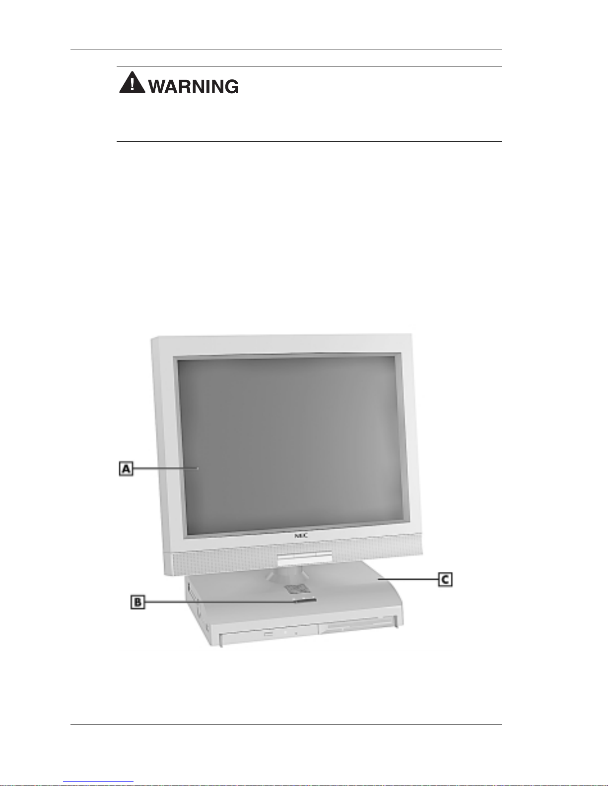
The following fig ures show th e features on th e front of the system u n it
and the front of the liquid crystal display (LCD) panel. Brief descriptions
of the features follow the figures.
PowerMate 2000 System
A
– LCD Panel
C
– System Unit
B
– Power/Sleep Button
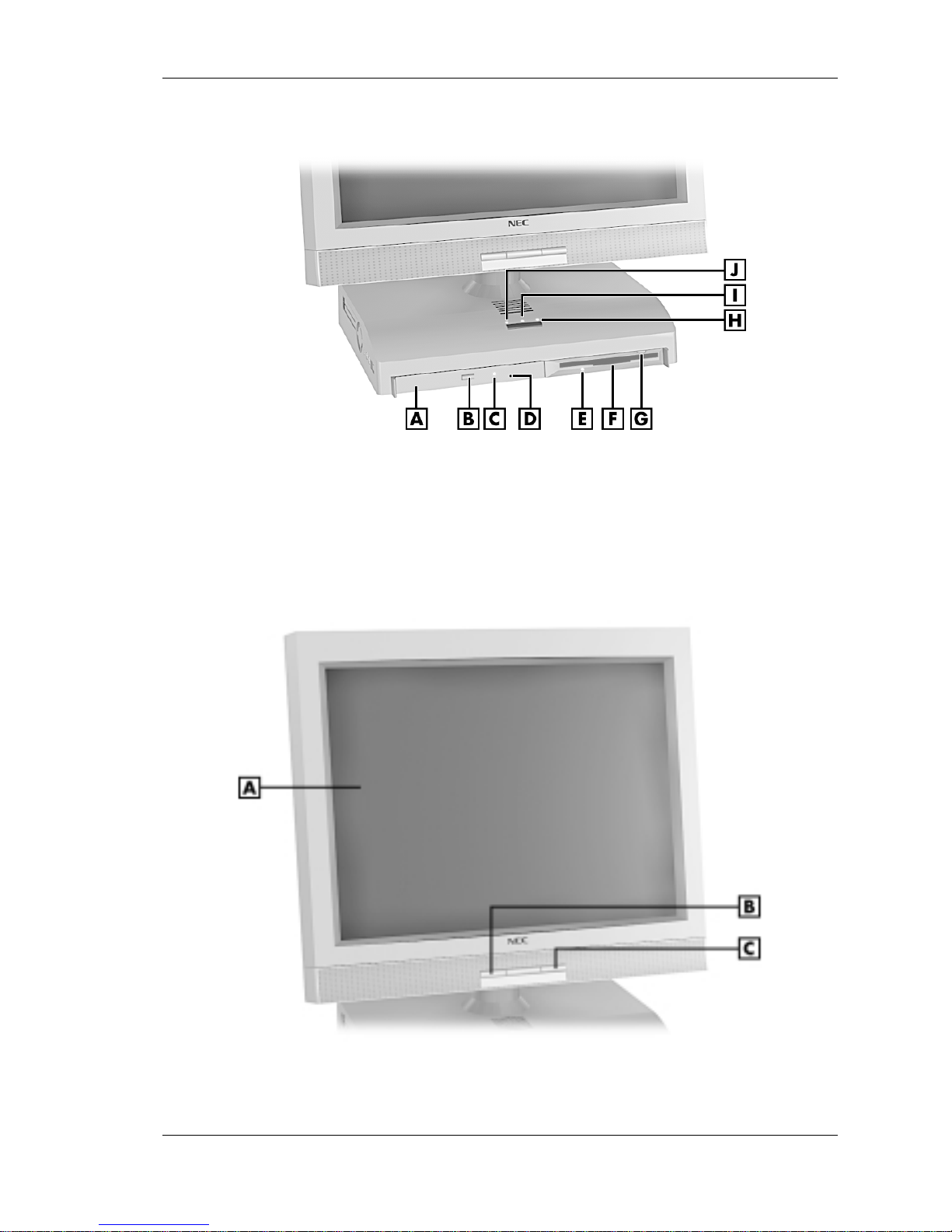
Reviewing System Features 1-3
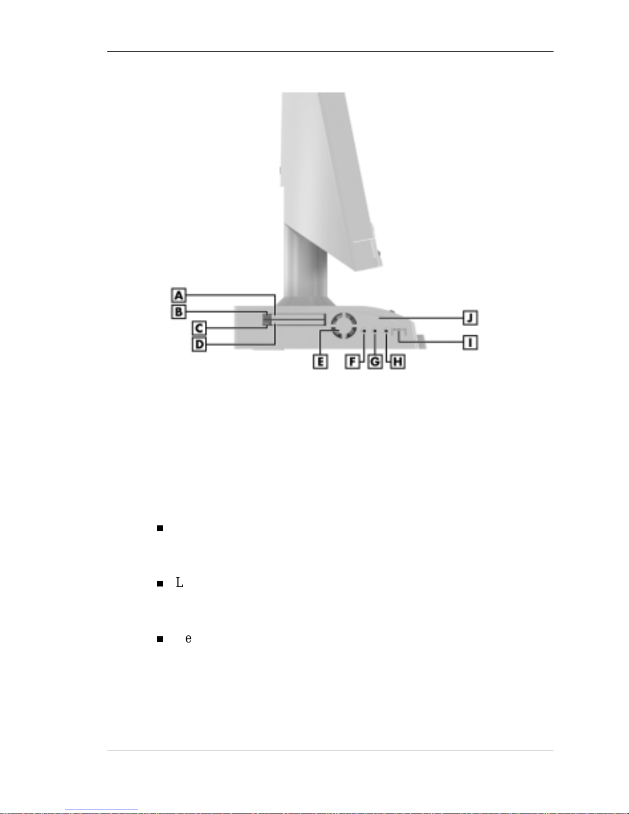
System u nit fro nt fe atures
A
– CD-ROM Drive
F
– Diskette Drive
B
– CD-ROM Eject Button
G
– Diskette Ej ect B u tton
C
– CD-ROM Drive Lamp
H
– Hard Drive Lamp
D
– CD-ROM Disc Emergency Eject
I
– Pow e r L amp
E
– Dis kette Drive Lamp
J
– Sleep Lamp
LCD panel features
A
– LCD Panel
C
– Increase Brightness Level Button
B
– Decrease Brightness Level Button
1-4 Reviewing S ystem Feat ures
System Controls and Lamps
System unit controls include a power/sleep button, power lamp, sleep
lamp, and hard drive activity lamp.
Power/sl eep butt on
To turn syst em unit and LC D pa nel power on, pre s s t he p owe r/ s leep
button. To turn off power, press the but t on an d h ol d in pla ce for four
or more seconds before releasing.
Do not turn off the system power until you have
clos ed all app lications and W indo w s or y ou may pos s ibly lose da ta.
To suspe nd system unit and LCD pan e l operation, press the
power /sleep button and rel ease with in three s econds or less. This
places the system unit and LCD panel in a power savings mode. Use
th is feature if you plan t o be awa y from your syste m for more tha n
15 minu tes.
Do not hold the button in any longer than three
seconds or you will turn off the system and possibly lose data.
Pres s any key or m ove t he mouse t o resume system operation at the
point where you stopped it.
Power and sleep lamp s
The power lamp indicates if system power is on or off. The sleep lamp
lets you kn ow if the system is op e rati ng in a power -sa ving mod e .
A stea dy green p ower lamp indicates that the power i s on to all system
compon ents . An amber sleep lamp indicates that the system is in sleep
mode with full-power reduction.
Hard drive activity lamp
A flashing green la mp in d icates th at th e hard drive is active and is
re ading or writ ing d a ta.
Do not turn off the system unless absolutely
necessary while t he ha rd dr iv e lamp is flashing. To do so can damage
your hard drive or data.

Reviewing System Features 1-5
LCD Panel
The system comes with an LC D panel that you can adjust up or down and
side-to-side for a comfortable viewing position. The panel uses a 15-inch,
twisted nematic Thin Film Transistor (TFT) Super Video Graphics Array
(SVGA) color screen. The screen has a brightness of 200 candlepower
and a maximum resolution of 1024 x 768 pixels.
The LC D panel s cr een automatica lly turns on when you p ress the s ystem
power button. I f you have an optional vid eo gra phics array (VGA)
mon itor atta ched to the system, the mon itor can be turned on for
simultaneous viewing on the monitor and the LCD panel.
An increase brigh tnes s but ton and a de c rease br ightn e s s button on the
panel allows you to increase or decrease the brightness of the display. The
buttons provide eight levels of brightness. The default brightness is
maximum.
Note
Powering off the system or unplugging the system from the power
outlet changes any new brightness setting to the maximum default
brightness.
Diskette Drive
Use the diskette drive to copy data files to and from a diskette. You can
also us e it a s a bootable drive for l oading and starting programs fr om a
diskette.
A flash i ng green activity lamp on the front of th e dri ve i ndi c ate s that the
drive is reading or writing data.
Pres s the eject button to eject a d iskett e.
To prevent damage to the diskette dr iv e and
data, do not turn off the system or remove a diskette while the diskette
drive busy lamp is flashing.

1-6 Reviewing S ystem Feat ures
Hard Drive
The system comes with either a 6.0-gigabyte (GB) or a 12- G B enhanced
intelligent device electronics (EIDE) hard drive. The drive features ultra
dir ect mem ory acce s s ( D MA ) 66 technolog y for fast data tra n s fer.
The drive is located inside the system unit, on the right side. The drive is
not user accessible.
Hard disk activity is indicated by a flashing green lamp on the front of the
system unit.
CD-ROM Drive
All systems come with a 24X Max Slim variable speed CD-ROM drive.
Use the CD-ROM drive to l oad and start programs from a compact disc
(CD) . You can also u se the CD-ROM drive to p lay your a u di o C Ds .
The C D-ROM drive operates at di fferent speeds d ep endin g on whether
the C D you are using contains data or music. This allows you to get your
data faster and to see smoother animation and video.
A flashing amber activity lamp on the front of the drive indicates that the
dri ve i s r eading dat a. Press the tray butt on to open or close the CD-ROM
tray for loading or unloading a CD. An emergency eject feature allows
you t o open the tray in case of a pow e r or s oftwa re m alfunction.
Speakers
The system has two 1-watt ster eo sp eakers mount ed inside th e ba s e of t he
LCD panel. S p eaker volum e is controlled by the volume con trol on the
left side of the system unit. Volume can also be controlled through the
Windows sound software.
Left Side Features
The following fig ure shows th e features on th e left side of the system u nit.
Brief descriptions of the features follow the figure.
Reviewing System Features 1-7
Left side features
A
– PC Card Slot 1
F
– Microphone In Jack
B
– Slot 1 Card Eject Button
G
– Line In Jack
C
– Slot 2 Card Eject Button
H
– Headphone Jack
D
– PC Card Slot 2
I
– Volume Co ntrol
E
– Fan
J
– System Unit
Audio Connectors
The system un it has th e following audi o connectors:
Microphone in jack
Use th is jack to connect a microphone for recording audi o inform ation
in your data files.
Line in jack
Use th is jack to connect a s tereo au d io device su ch as a st er eo
amplifier or a c asse tte for playback or r e cord i ng.
Headphone jack
Use th is jack to connect an opti on al head phone set . P lugging in the
headphon e s et disa bl es the buil t-in system spea kers.

1-8 Reviewing S ystem Feat ures
Volume Control
Use the volume control to adjust the volume of the system’s built-in
speak ers or optional headphone set. The speakers ar e located in the bas e
of the LCD panel.
You can also use the Windows sound software. To bring up the Windows
volume control, double click the speaker icon on the taskbar (next to the
system clock). Use the software to balance th e s ou nd between th e left and
right speakers.
PC Card Slots
Your system has two PC card slots that support 16-bit PC card technology
and 32-bit CardBus technology. The CardBus technology provides up to
132 MB/second of bandwidth.
The card slots support two Type II cards or one Type III PC card in the
bottom slot for extending the system’s capabilities. Each type of PC card
ha s a different function . Us in g t he P C c ard s lots , you can add a number of
function s t o the system with a var iety of cards (for example, modem ,
memory, Small Computer System Interface).
A PC card is inserted into a PC card slot similar to inserting a diskette in a
disk ette drive. Pres s the eject button to eject a PC card.
Remova ble slot c over s keep forei gn ma tter out of th e slots when PC cards
are not used.
Fan
The fan cools s ystem un it component s and prevents them from
overheating. Keep the area near the fan clear for proper vent ilati on.
A featu re of the fan is its qu ietnes s. The fan operates at less th an 30 db.
Rear Features
On th e rear of the s ystem un it are the universal seri al bus (USB) p orts, DC
power conn ect or , mouse and keyboard ports, and other ext ernal d evi ce
connectors. Th e following figure shows the port s and conn ectors.
Descriptions of each follow the figure.
Reviewing System Features 1-9
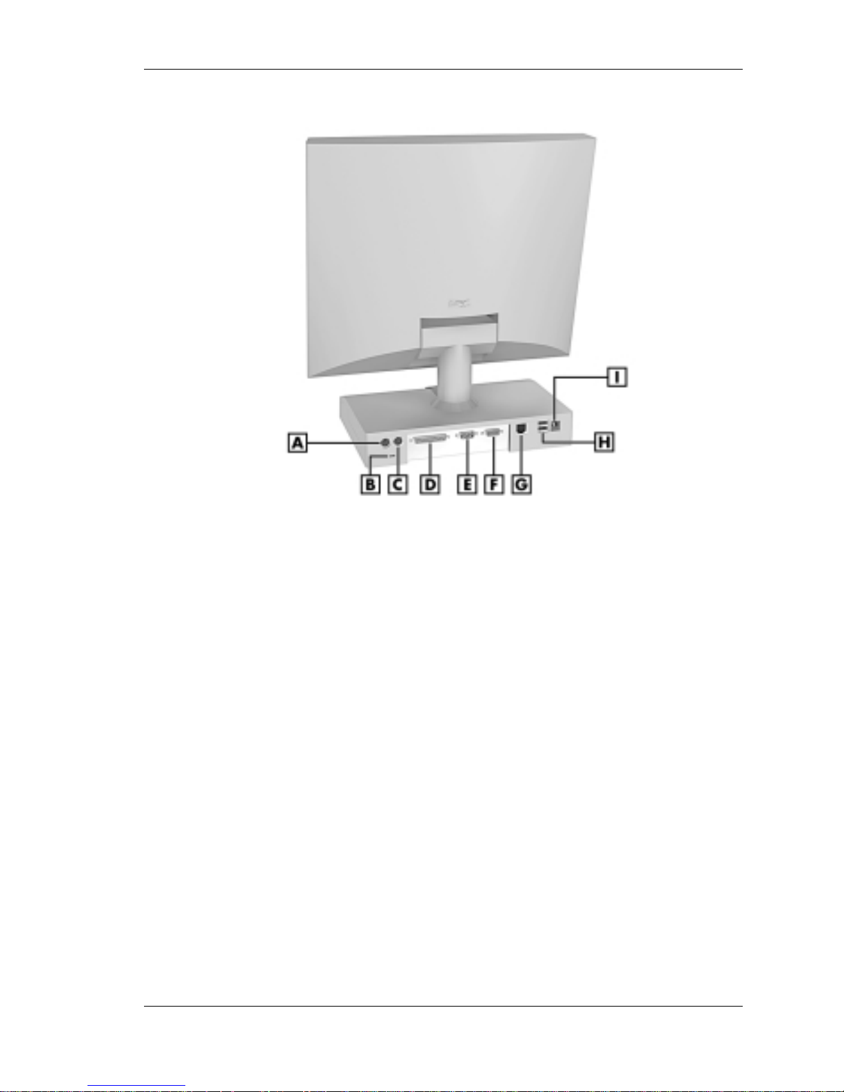
Rear features
A
– PS/2 Mouse Port
F
– VGA Connect o r
B
– Kensington Lock Slot
G
– LAN Connector
C
– PS/2 Keyboard Port
H
– USB Connectors
D
– Printer Port
I
– DC Power Connector
E
– Serial Port
Universal Serial Bus Ports
The system un it comes with two USB ports on the rear of the system u n it.
The ports allow you to easily and conveniently add plug and play USB
devices without opening up the system. You simply plug the USB device
in to a port. Y ou can conn e c t up to 12 7 US B devices in c ludin g a keyboard ,
mouse, monitor, printer, scanner, or speaker set.
DC Power Connector
The system operates wi th DC power supplied from the AC power adapter.
The a dapter p lu g s in to an AC power s ource and the DC power conn ect or
on the rear of th e s ystem uni t. The AC power adapter uses a s tandar d
115-Vac or 230-Vac grounded power source.

1-10 Reviewing S ystem Feat ures
PS/2 Mouse Port
The system unit comes with a mouse port that supports a
PS/2
®
-compatible (personal system/2-compatible) mouse with a 6-pin
mini D I N connector.
Use this port to connect the PS/2 mouse shipped with your system.
PS/2 Keyboard Port
Your system unit com es wit h a keyboard port that s upports a standard
PS/2 101-key or 104-key keyboard with a 6-pin mini DIN connector.
Use this port to c onn e ct the PS/2 ke yboard shipped wi t h your sys tem.
VGA Monitor Connector
The system unit comes wi th a VGA connector on the rear of the s ystem
unit.
Use th is conn ector to connect an op tiona l NE C M ul tiSync
®
monitor, NEC
VistaScan™ m onitor, or other VGA-compatible m oni t or with a 15-pin
connector . Y ou can als o at tach a pr oject or with a 1 5- p in conn ector to this
connector.
The system supports simultaneous use of the LCD panel and an optional
mon itor conn ected to the VGA connector .
Print er Port
Use th is port t o connect a parallel prin t er with a 25 -pin conn ector t o th e
system unit. The port is an enhanced capabilities port (ECP). It also
supports enhanced parallel port (EPP) bi-directional and uni-directional
protocols.
Serial Port
Att ach a seria l device with a 9-pin con nector to this s er ial port. Seria l
devic es in clude a poin ting device, ser ial prin ter, or a mod em.
Reviewing System Features 1-11
LAN Connector
System s come wit h a local area networ k (LAN). Use the RJ-45
compa tible LA N conn ector on th e rear of the s ystem to connect a n etwork
cable to the internal 100Base-TX/10Base-T network board.
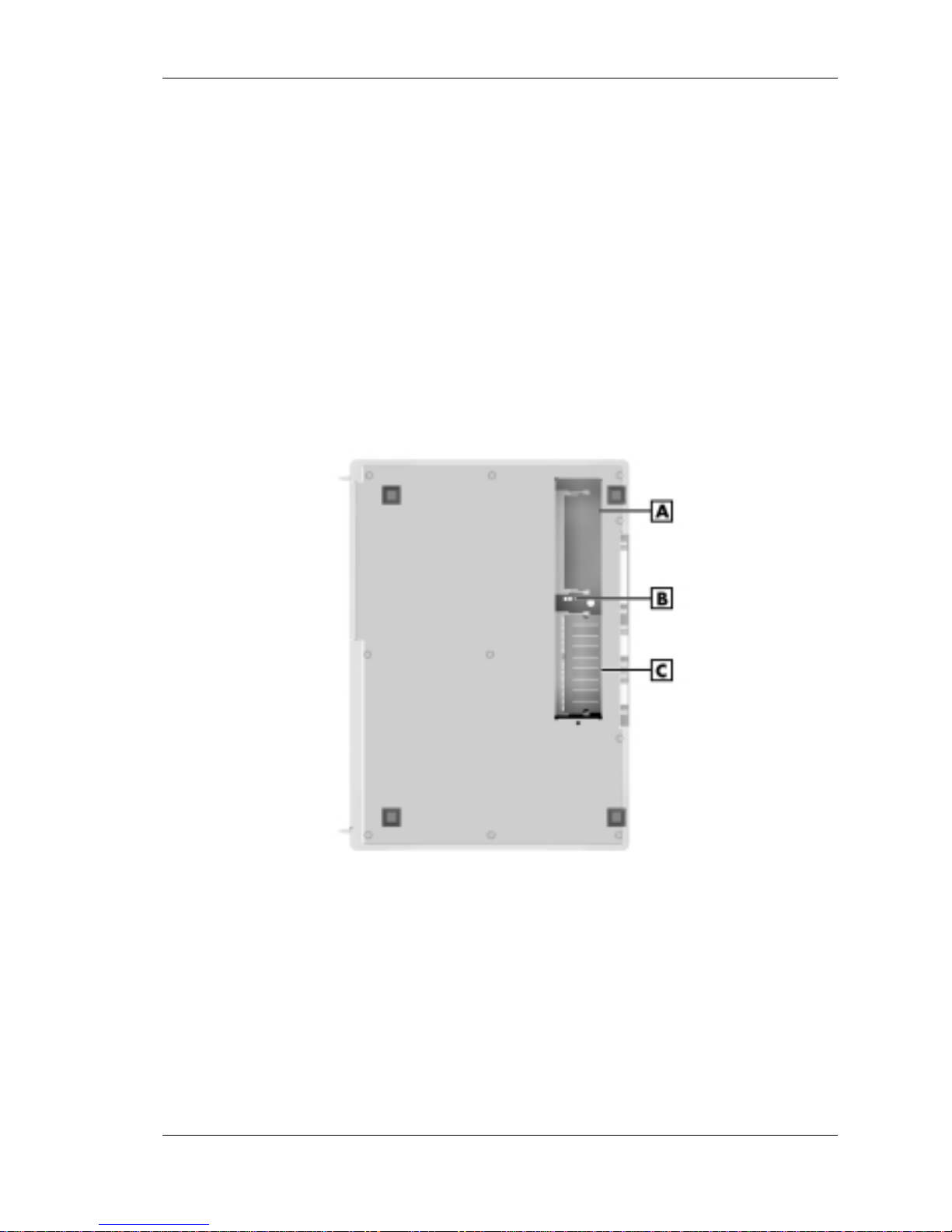
Bottom Features
A panel on th e bottom of the sys tem unit covers the m e mory expansion
socket s and th e pa s sw ord cl ear jumper. (See Chap ter 4, “Adding
Expansion Devices,” for information on removing the panel.)
Bottom features
A
– SO-DIMM Socket 1
C
– SO-DIMM Socket 0
B
– Password Clear Jumper

1-12 Reviewing S ystem Feat ures
Memory Sockets
The system unit comes wi th at least one 64 - M B small out line dua l-inline
memory module (SO-DIMM) mounted in one of two memory sockets.
You can increase total system memory to a maximum of 512 MB by
using two 256-MB modules (see “Adding Memory Modules” in
Chapter 4).
The modules use synchronous dynamic random access memory
(SDRAM). Memory allocation is controlled by Dynamic Video Memory
Technology (DVMT). With DVMT, total system memory is shared
between system memory and video mem ory. F or example, with 64 MB of
total system memory, 56 MB might be allocated for system memory and
8 MB for video memory, with actual memory use dependent on video
usage.
Password Clear Jumper
Use the password clear jump er ( 7F4) to cl ear your pass w ord if you forgot
it. To clear and reset the password, see “Jumper Settings” and “Security
Menu” in Chapter 3.
Microdesktop Chassis
The NEC Microd esktop chass is conforms to NEC ’s Very-Small Form
Fact or and Flat Panel Di sp lay Specificat i on. The microdes k top ha s th e
following features:
small size chassis that is 85 percent smaller and correspondingly
lighter than traditional desktops
15-inch LCD panel with 1024 x 768 pixel maximum resolution, eight
levels o f dis play brigh t nes s , horizontal vi ewin g a ngle of 60 degrees
from cent er to right or le ft si de of panel, vert ical viewin g angle of 40
degrees from center of panel and upwards and 50 degrees from center
of panel and downwards
90-watt power supply (built into the AC power adapter).

Reviewing System Features 1-13
System Overview
The system har dware and software del iver th e performance an d
technologies n eed ed for all your cha llenging task s tod ay and into the
future.
Hardware
The PowerMate 2000 Series includes the following hardware features:
PC99 Compliance
All the hardware in the system is certified by Microsoft
®
to be PC99
compliant.
Processor
The system comes with an Intel
®
Pentium® III proce sso r (100-MHz
front s ide bus) . The processor is a fast, powerfu l proces sor t hat len ds
itself to computational, graphical, and networking tasks.
Audio
Th e s ystem board comes with an integrated a udio s ubsys tem . Th e
audio chipset gives you a surround sound system for threedi mens ional soun d effect s. It also provides wavetable s ynthes is.
Flash abl e ROM BIO S
The system’s ROM BIOS features system setup configuration, Plug
and Play support, and flash support for economical BIOS upgrades.
System and Vid eo Memory
Your system comes with at least 64 MB of non-ECC PC100 SDRAM
and supports up to 512 MB of total system memory. The memory uses
DVMT technology which allows system memory to be shared with
video memory. For example, with 64 MB of total system memory,
56 MB might be allocated for system memory and 8 MB might be
allocated for video memory (actual usage depends on video usage).
AGP Graphics
The system comes with an a cceler ated graphics port (AGP) integrated
on the system board. AGP enhan ces gr aphics p erformance,
particularly for 3-D applications.
Power Management Options
Power management options extend the life of your LCD panel,
conserve energy, and redu ce p ower costs .

1-14 Reviewing S ystem Feat ures
Software
NEC provides a variety of software applications and hardware utilities
with your system to let you take advantage of your hardware capabilities.
Preloaded Microsoft Operating System
Your system comes preloaded with the Microsoft® Wind ows® 98 SE
opera ting syste m or with a dual-boot Wind ows NT
®
4.0 and Windows
®
2000 operating system.
NEC OS Restore CD
Your system comes with an NEC OS Restore CD and boot able di s k ette.
The C D con tains th e Windows 98 operat ing system or th e dual-boot
Windows NT/Windows 2000 operating systems, depending on your
model.
Shou ld a problem occu r tha t causes d ata loss or corr up t ion, you can
re s tore your system to its or i ginal fac tory sta te or you can res tore jus t t he
operating system and dri vers. You can also perform har d drive
partitioning.
After restoring th e op eratin g s ystem, you ca n use the Applicati on and
Driver CD to install your applications, drivers, and NECC online
documents.
NEC Application and Driver CD
Your system comes an NEC Application and Driver CD. Use this CD to
install any or all of the software that comes wit h the system , in cluding:
Microsoft® Internet E xplorer Brows e r
Internet Explorer provides a top-notch browser with preloaded links
for easy access to the world wide we b. A lso use In ternet Explorer to
acce s s one of t he ma ny n e w brows er- based utiliti es.
Norton AntiVirus™ 2000 Software
Pr otect the syst em from viru s e s by run ning Norton’s virus scan
software.

Reviewing System Features 1-15
Adobe® Acrobat® Reader
Use the Adobe Acrobat Reader to read and print portable d ocumen t
format (PDF) files found on the Internet and PDF documents included
with various software applications.
Intel LANDesk® Client Manager
Use LANDesk software to track system information such as serial
number, BIOS version, memory capacity, disk capacity, expansion
board sett ing s, and application s. Use LANDesk software for rem ote
starts from a s er ver compu ter usin g Wa ke-On LAN an d r em ote reboot.
NEC INFO Center
The NEC INFO Center an online version of this user’s guide, and
Tour, Questions, Solutions, and Services modules.
Select the Tour module to look at the documentation, tools, and
servi ces that com e wi th the system. The Ques tions mod u le inclu des
answers to frequently asked questions. Use the solutions module to
find possible solutions to system problems. The Services module
cont ains service information such as where to go on the In tern et for
help, who to call for service, and more.
A wide selection of drivers
Drivers for hardware that is compatible with PowerMate series
computers ar e provided with the original manu factur er ’s instal lati on
wiza r ds to ensure correct installation .
Security
The system has hardware, soft ware, and mechani cal security feat ures tha t
offe r prot ec tion against un author i zed a c ce s s to your syst em a nd data. The
foll o wi ng security featur es ar e available with the system .
Password security
The BIOS Setup utility includes a feature that lets you set a user or
super visor pa s s wor d, or both .
The u ser password con trols booting of the system and controls access
to th e Setup uti lity an d the keyboard. (User access to the BIO S S etup
utility is limited to a subset of all BIOS Setup parameters when a
supervisor password has been set.)
The su pervisor passw ord allows full access to the system an d th e
BIOS.

1-16 Reviewing S ystem Feat ures
Secur ity Lock Slot
The secu rit y lock slot on the rear of the system a ccepts a K ensing ton
®
Secur ity Standard con nector or other locking d evi ce. Secure th e
locking device to the security lock slot and to an immovable object to
protec t your system from th e ft.
Hard Drive Securit y
Your system supports password protection for the hard drive. Hard
dri ve password pr ot ection r estri cts access to the drive if th e dr ive is
re moved a nd installed in another s ys tem . Th e s ystem does not pr ompt
for hard drive passwords wh i le the dri ve remains in the current
system.
The p asswords are written to th e system BIOS a nd to the hard dri ve t o
ensure tha t the pass wor d prot ection tr avels wit h the hard drive i n the
even t it is moved t o another system . (See “Har d Drive Security” in
Cha p ter 3 for ad di tional informati on on u sing this featur e.)
Win dows network secur ity features
To learn more about the network security features available through
the Windows operat ing system, refer to your Windows doc u mentation
or c onsult your system administrator.

2
Setting Up the System
Cable Connections
Startup
Shutdown
Power-Saving Opera tion
Sys tem Care
More Inform atio n

2-2 Setting Up the System
Th is chapter pr ovide s basic informa t ion for sett ing u p a nd usi ng you r
system ( refer to the Qui ck Setup poster for details ) . Inclu d ed are cabl e
connecti ons, system s tartup procedu res, syst em shutdown procedures, an d
system care. The chapter al so includes a table showing wh er e to find
additional information about your system.
Cable Connections
After unpacking the system (save the carton) and positioning the system
in your work area, connect the system comp onent s u s in g the Quick Setup
poster and the following tips.
Use the icons on the rear and side of the system u n it to id entify th e
USB, keyboard, mouse, LAN, printer, monitor, power, and audio
connectors.
See your network adm inis t rator for guide lines on configur i ng the
LAN.
Conn ect the s ystem AC adapter power cord to a surge pr otector
(r ecom mended) or a prop er ly grounded wal l outlet and to the DC
power conn ector at the rear of the system unit.
NECC recommends co nnec t in g the AC adapter
power cord to a surge protector to protect y our system.
Startup
Press the power button to turn on the system unit and LCD panel. The
power lamp lights green to indicate that th e system is on. The system
performs its Power-On Self-Test (POST) and several messages appear on
the screen in d icating that the system is checking its subsystem s .
Note
At t he bo t tom of the NEC star tup screen, the f ollowing mess age
appears:
Press F2 to enter BIOS Setup
. If you want to enter the BIOS
Set up Ut ility, immedi ately pr ess
F2
while the start up screen d is plays. ( See
Chapter 3, “Configuring the System,” for information on using the BIOS
Setup.)
After a shor t d elay, Windows starts up .
Setting Up the S ystem 2-3
If a problem oc cur s, a series of beeps might s oun d. If th is happen s
repeatedly after powering on, power off the system and go to Chapter 5,
“Solving System Problems.” The chapt er provides helpful hint s for
solving system problems.
If the system displa ys a messag e indi cating that system settings have
changed, run the BIOS Setup Utility (see Chapter 3, “Configuring the
System”).
On syst ems loaded with the Wind ows N T
®
4.0 or Windows 2000
operating system, press
Ctrl Alt Del
when pr ompte d on -scr e e n to d o s o.
Th e log- on box app ea rs for entering a passwor d.
Shutdown
Follo w t hese st eps to power of f t he system.
To prevent damage to system compon ents , wake
a syst em in sleep mode, save an d close an y open applications, exit
Windows, and power down the system.
1.
If the system is in sleep mode (sleep mode lamp amber), move the
mouse or press a k ey to t ake it out of sleep mode (see “Power Saving
Operation ” in the next s ection ).
2.
Save and exit all your open a pplicati ons.
3.
Make s ure tha t the hard drive, diskett e drive, and any other drives are
not in us e. A lit devi ce l amp indicates that th e device is in use.
Wait until all open applications are saved and
clos ed before using the Wi ndows shut down pr oced ure in step 4.
Unless absolutely necessary, never power off the system if the system
sleep lamp is amber, if either the hard dri ve lamp, diskette drive, or other
device lamp is flashing, or if any applications are open. Information on the
device might be lost or damaged.

2-4 Setting Up the System
4.
Click
Start
on the taskbar and click
Shut Down
. Select
Shut down
th e computer
, then click
Yes
or press
Enter
for shut down,
dep e nd ing on your operating s ystem.
If the system is configured with Windows 98 or Windows 2000,
the system sh u ts down a ut om atica lly after a short in terval.
If the system is confi g ured with Windows NT , and aft er you
perform a Windows shut down, power off the system by pressing
and holding in the power button for four seconds or longer
before releasing.
Power-Saving Operation
If the system is running Windows 98 or Windows 2000, you can put it in
sleep mode (a power-saving state) by pressing and immediately releasing
the p ower button on the front of th e s ystem uni t. The sl eep mode is a
conven ien t way of conservin g energy when you ar e g oing to be away
from your system for more than 15 minutes.
Take ca re to press and immediately r elease the
power b utton to enter th e sleep mode. A voi d pressing an d holding in the
power button longer than three seconds or you may turn off power and
possibly lose data from any open applications.
The system al so g oes into sleep mode when it ha s been ina ct ive, if th e
power management has been enabled in BIOS, and an inactivity timeout
has been ena bl ed . ( S ee Chapter 3, “Confi guring You r System ,” for
information on setting power management functions.)
When the system goes into sleep mode, it automatically saves data an d
system stat u s and then sh u ts off power to all possi ble comp onen ts. Sleep
mod e lets you save power wit hou t first saving your work.
An amber sleep lamp indi cates th at the system is in sl eep mode. Press a
key or move th e mouse to resume system operation where you left off.

Setting Up the S ystem 2-5
System Care
The system is a durable system built for depen dable use. With pr otective
measures and prope r care, you c an prevent problems a nd prom ote the
succes sful opera tion and long life span of the system.
Protecting Your System From Damage
There are several ways that you can pr ot ect th e system from p oss ible
damage. NECC strongly recommends the followin g protective measures.
Conn ect a sur g e suppr ess or bet ween the system and a grounded wall
outlet. A surge suppressor protects the system from sudden transient
increases an d decrea s es in electri cal power.
Be sur e to connect all per ipher als, such as a print er, to the su rge
suppressor. The surge protector should be the only de vice that you
plug into the wall outlet.
Avoid r ep eated power-on cycles. These su bj ect the system
components to temper ature variations and stress.
Disconnect the system from t elephone and power lines when an
electrical stor m th reatens. If you h ave a fax/ modem, lightn ing can
tr avel i n on the ph one li ne and damage both the fa x/m odem and the
system u n it. Lightning can also travel in on power lines an d damag e
the LC D panel an d system unit.
Be sur e th at system power is off befor e conn ecting or disconnecting a
cable ( US B d evices do not requir e p ower ing d own th e s ystem when
connecting). Never make cabl e ch anges when the system power is on.
Doin g so can dama ge the s ystem and it s p er iphera ls.
Use BIOS Setup Utility options to protect against viruses (see
Chapter 3). You shou ld also u s e t he Norton virus sca n prote c tion
softwa re provi ded with the s ystem to protect the s ystem from viruses.
If you plan to use s oftwar e program s ot her than NEC C-supplied
soft wa re, NECC strongly recomm en d s th at you ta k e th e n eces sar y
steps , such as virus ch eck s , to pr ot ect the system.
Position the system away from direct sunlight and extreme h ot and
cold temperatures.
The r ecom mended operating environ ment is fr om 50°F to 95°F (10°C
to 35°C).
 Loading...