

Page 1

Proprietary Not ice and Liability Disclai mer
The information disclosed in this document, including all designs and related
materials, is the valuable property of NEC Computers Inc. and/or its licensors.
NEC Computers and/or its licensors, as appropriate, reserve all patent, copyright
and other proprietary rights to this document, including all design, manufacturing,
reproduction, use, and sales rights thereto, except to the extent said rights are
expressly granted to others.
The NEC Computers product(s) discussed in this document are warranted in
accord ance with the terms of the Warr anty Sta tem ent accomp anyin g ea ch produ ct.
However, actual performance of each such product is dependent upon factors such
as system configuration, customer data, and operator control. Since
implementation by customers of each product may vary, the suitability of specific
product configurations and applications must be determined by the customer and is
not warranted by NEC Computers.
To allow for design and specification improvements, the information in this
document is subject to change at any time, without notice. Reproduction
of this document or portions thereof without prior written approval of
NEC Computers is prohibited.
NEC, PowerM ate, and MultiS ync a re re gistered trademar ks and AccuSync is a trad emark of
NEC Corporation or one of its su bsidia r ies. Al l are us ed under license.
Microsoft, Win dows, Windows NT, an d the Win dows logo a re regist ered trademarks of
Microsoft Corporat ion.
Intel, Pentium, and LANDesk are registered trademarks of Intel Corporation.
All other trademarks and registered trademarks are the property of their respective
trademar k ow ners .
First Printing — May 2001
Copyright 2001
NEC Computers Inc.
15 Business Park Way
Sacramento, CA 95828
All Rights Reserved
Page 2

Contents
Using This Guide
Text Conventions........................................................................................x
Related Documents................................................................................... xi
1 Reviewing System Features
Front Features ......................................................................................... 1-2
System Controls and Lamps ............................................................ 1-4
LCD Panel...................................................................................... 1-5
Diskette Drive................................................................................. 1-5
CD-ROM Drive.............................................................................. 1-6
Optional Combo Drive.................................................................... 1-6
Speakers......................................................................................... 1-6
Right Side Features................................................................................. 1-7
Volume Control.............................................................................. 1-7
Audio Connectors........................................................................... 1-8
Universal Serial Bus Ports............................................................... 1-8
Hard Drive......................................................................................1-8
Anti-theft Bracket........................................................................... 1-8
Left Side Features ................................................................................... 1-9
PC Card Slots................................................................................. 1-9
System Unit Fans.......................................................................... 1-10
Rear Features........................................................................................ 1-10
PS/2 Mouse Port ........................................................................... 1-11
Kensington Lock Slot ................................................................... 1-11
PS/2 Keyboard Port ...................................................................... 1-11
Printer Port ................................................................................... 1-11
Serial Port..................................................................................... 1-11
LAN Connector............................................................................ 1-11
Optional Modem Connector.......................................................... 1-12
VGA Connector............................................................................ 1-12
DC Power Connector.................................................................... 1-12
Bottom Features.................................................................................... 1-13
Memory Sockets........................................................................... 1-13
Password Clear Jumper................................................................. 1-14
Microdesktop Chassis........................................................................... 1-14
System Overview.................................................................................. 1-15
Hardware...................................................................................... 1-15
Content s iii
Page 3

Software........................................................................................ 1-16
Preloaded Software................................................................1-16
NEC Product Recovery CD ...................................................1-16
PowerMate Application and Driver CD..................................1-16
Security .........................................................................................1-17
2 Setting Up the System
Cable Connections...................................................................................2-2
Startup.....................................................................................................2-2
Shutdown................................................................................................2-3
Power-Saving Operation..........................................................................2-4
System Care ............................................................................................2-5
Protecting Your System From Damage............................................2-5
Keeping Your System in Good Condition ........................................2-6
Moving or Shipping Your System....................................................2-7
More Information ....................................................................................2-8
3 Configuring the System
Configuration Tools and Utilities.............................................................3-2
BIOS Setup Utility...................................................................................3-4
How to Start Setup...........................................................................3-4
How to Use Setup............................................................................3-4
Main Menu......................................................................................3-6
Advanced Menu ............................................................................3-12
Security Menu...............................................................................3-17
Power Menu ..................................................................................3-21
Boot Menu....................................................................................3-22
Exit Menu .....................................................................................3-24
Hard Drive Security...............................................................................3-25
Establishing Hard Disk Drive Passwords........................................3-25
Changing Hard Disk Drive Passwords............................................3-26
Using Hard Disk Drive Password Protection..................................3-26
Moving the Hard Drive..................................................................3-27
FLASH Utility.......................................................................................3-28
NEC Customize Utility.......................................................................... 3-28
PowerMate Application and Driver CD..................................................3-29
NEC INFO Center.................................................................................3-30
NEC Product Recovery CD....................................................................3-31
Performing Full Disk Restore.........................................................3-32
Performing Partition Only Restore.................................................3-34
System Board Jumper Settings...............................................................3-36
iv Contents
Page 4

Intel Processor Serial Number Control Utility........................................ 3-37
System Requirements.................................................................... 3-37
Installation.................................................................................... 3-38
Processor Serial Number............................................................... 3-38
Frequently Asked Questions.......................................................... 3-38
Technical Support......................................................................... 3-40
4 Adding Expansion Devices
Safety Precautions................................................................................... 4-2
USB Devices .......................................................................................... 4-3
PC Cards ................................................................................................ 4-4
Inserting a PC Card......................................................................... 4-4
Removing a PC Card ...................................................................... 4-6
Memory Modules.................................................................................... 4-7
Checking System Memory.............................................................. 4-8
Installing a SO-DIMM Module....................................................... 4-8
Removing a SO-DIMM Module.................................................... 4-11
Hard Drive............................................................................................ 4-12
Removing a Hard Drive................................................................ 4-12
Installing a Hard Drive.................................................................. 4-14
Parallel Printer...................................................................................... 4-15
External Monitor................................................................................... 4-15
Serial Devices....................................................................................... 4-15
5 Solving System Problems
Solutions to Common Problems.............................................................. 5-2
System Problems............................................................................ 5-2
Diskette Drive Problems................................................................. 5-4
LCD Panel Problems....................................................................... 5-5
Keyboard/Mouse Problems............................................................. 5-5
CD-ROM Drive Problems............................................................... 5-6
Speaker Problems........................................................................... 5-7
How to Clean the Mouse......................................................................... 5-7
6 Getting Services and Support
NEC Computers Web Site....................................................................... 6-2
NEC Computers FTP Site....................................................................... 6-3
Email/Fax Technical Support Service ...................................................... 6-3
NEC Computers Technical Support Services........................................... 6-4
Content s v
Page 5

A Setting Up a Healthy Work Environment
Making Your Computer Work for You....................................................A-2
Arrange Your Equipment........................................................................A-3
Adjust Your Chair ..................................................................................A-4
Adjust Your Input Devices......................................................................A-6
Adjust Your Monitor ..............................................................................A-8
Vary Your Workday.............................................................................A-10
Pre-existing Conditions and Psychosocial Factors..................................A-11
Checking Your Comfort: How Do You Measure Up? ............................A-11
Checking Your Chair.................................................................... A-11
Checking Your Keyboard.............................................................A-12
Checking Your Mouse..................................................................A-12
Checking Your Monitor................................................................A-12
Checking You...............................................................................A-12
B System Specification s
System Board .........................................................................................B-2
System Processor............................................................................B-2
Random Access Memory (RAM)....................................................B-2
Cache Memory...............................................................................B-2
Read Only Memory (ROM)............................................................B-2
Calendar Clock...............................................................................B-2
Input/Output (I/O) Features.............................................................B-3
Video Memory ...............................................................................B-3
Sound Controller............................................................................B-4
Network Board...............................................................................B-4
Modem Board ................................................................................B-4
Graphics Controller ........................................................................B-5
System Peripherals..................................................................................B-5
LCD Panel......................................................................................B-5
External Monitor............................................................................B-6
Keyboard........................................................................................B-6
Mouse ............................................................................................B-7
Diskette Drive ................................................................................B-7
Hard Drive.....................................................................................B-7
CD-ROM Drive..............................................................................B-7
Combo Drive..................................................................................B-8
PC Card Slots.................................................................................B-8
Speakers.........................................................................................B-8
vi Contents
Page 6

Dimensions.............................................................................................B-8
System............................................................................................ B-8
Keyboard........................................................................................B-8
Power .....................................................................................................B-9
Opera t ing Env ironment...........................................................................B-9
Compliance.............................................................................................B-9
Index
Regulatory St at ements
Contents vii
Page 7

Using This Guide
The PowerMate® 2000 Series User’s Guide provides a comprehensive
reference to information about your system.
The gui d e contains the following informati on :
Chapter 1, Reviewing Syst e m Fea ture s , pr ovides a look at th e front ,
sides, rear, and bottom featu res of the system. It also gives a summary
of the syst em ’s hard ware, software, and security feat u res.
Chapter 2, Setting Up the System, briefly describes how to set up, start
up, and shut down the system. The chapter also provides information
on in st al ling appl ications and tip s on car ing for the system.
Chapter 3, Configuring the System, describes how to use the software
shipped with your system, including the BIOS Setup Utility, FLASH
Utility, NEC
CD, NEC INFO Center, NEC Product Recovery CD, and Intel
Pentium® III Serial Number Control Utility. The chapter also includes
information for setting the password jumper.
Chapter 4, Adding Expansion Devices, provides installation
procedures for adding expansion devices such as USB devices, PC
cards, memory upgrade modu les, hard d r ive, extern al monito r, and
printer.
®
Customize Utility, Power M ate® Application and Driver
®
Chapter 5, Solvin g S ystem Proble ms, cont ai ns trouble s hootin g tips for
solving simple problems and describes how to find help when you
cannot solve a proble m yourself.
Chapter 6, Getting Services and Support, describes the services
available to you for infor mation and help, an d d escribes how to access
the services.
Appendix A, Setting Up a Healthy Work Environment, contains
guidelines to help you use your computer productively and safely.
This appendix also instructs you on how to set up and use your
computer to reduce your risk of developing nerve, muscle, or tendon
disorders.
Appen di x B, System Sp ecifications, pr ovi d es a technical descr iption
of your system and its componen ts.
Using This Guide ix
Page 8
workstation may pose a risk of serious injury. To reduce your risk of injury,
set up and use your computer in the manner described in Appendix A,
Setting Up a Healthy Work Environment.
Text Conventions
This guide uses the following text conventions.
Warnings, ca ut ions, and notes have the following meanings:
in serious personal injury or loss of life.
hardware or software.
Prolonged or improper use of a computer
Warnings alert you to situations that could result
Cautions indicate situations that can damage the
Note
described.
Notes give important information about the material being
Names of keyboard keys are prin ted as the y appear on the keyb oard,
for example,
Text or keystrokes that you enter appear in boldface type. For
example, type
File names are printed in uppercase letters. For example,
AUTOEXEC.BAT.
x Using This Guide
Ctrl, Alt
abc123
Enter
, or
and press
.
Enter
.
Page 9

Related Documents
In addition to this guide, the following printed documentation ships with
your system.
NEC PowerMate 2000 Series Quick Setup/Quick Reference
The Quick Setup shows how to qui ckly get th e s ystem conn ected and
powered on.
The Quick Reference briefly describes the documentation, NEC tools
and utilities, software applications, and services available with the
NEC PowerMate 2000 Series system.
How Does Your Workplace Measure Up?
This brochure provides i nformat ion for set t ing up a nd us ing the
computer productively and safely. Information includes guidelines to
redu ce the risk of injury associated wi th using a com p u ter.
NEC PowerMate 2000 Series Release Notes
Release Notes provide additional information about the computer that
was not available at the time the user’s guide was printed. Information
in the Release Notes is the result of product testing.
Your system also com es with the NEC INFO Center, an on line guid e to
your PowerMate 2000 system. It provides information about the system
through the following online modules: Tour, User’s Guide, Questions,
Solutions, and Services.
In addition to the documentation that ships with the system,
documentation is available from the NEC Computers web site.
NEC PowerMate 2000 Series Service and Reference Manual
This man ual pr ovides informa t ion for maintaining, tr oubleshoot ing,
and repairing the system. This manual also includes hardware and
interface information for programmers, engineers, and others who
need t o know how the syst em is designed.
Service and reference manuals ar e ava ilable on the Inter net at the
Service and Support area of the NEC Computers web site (see
Chapter 6 for access information).
NEC PowerMate 2000 Series User’s Guide
Check the NEC Computers web site (Service and Support area) for the
most current online version of your printed user’s guide.
Using This Guide xi
Page 10

Reviewing System Features
Front Features
Right Side Features
Left Side Features
Rear Features
Bottom Features
Microdesktop Chassis
System Overview
1
Page 11
workstation may pose a risk of serious injury. To reduce your risk of injury,
set up and use the computer in the manner described in Appendix A,
“Setti ng Up a Healthy Wo r k Envi ronment . ”
This chapter highlights system hardware and software features, and
describes system secur ity features.
Front Features
The foll o wi ng fig ures show the fea tures on the front of the system un it
and the front of the liquid crystal display (LCD) panel. Brief descriptions
of the features follow the figures.
Prolonged or improper use of a computer
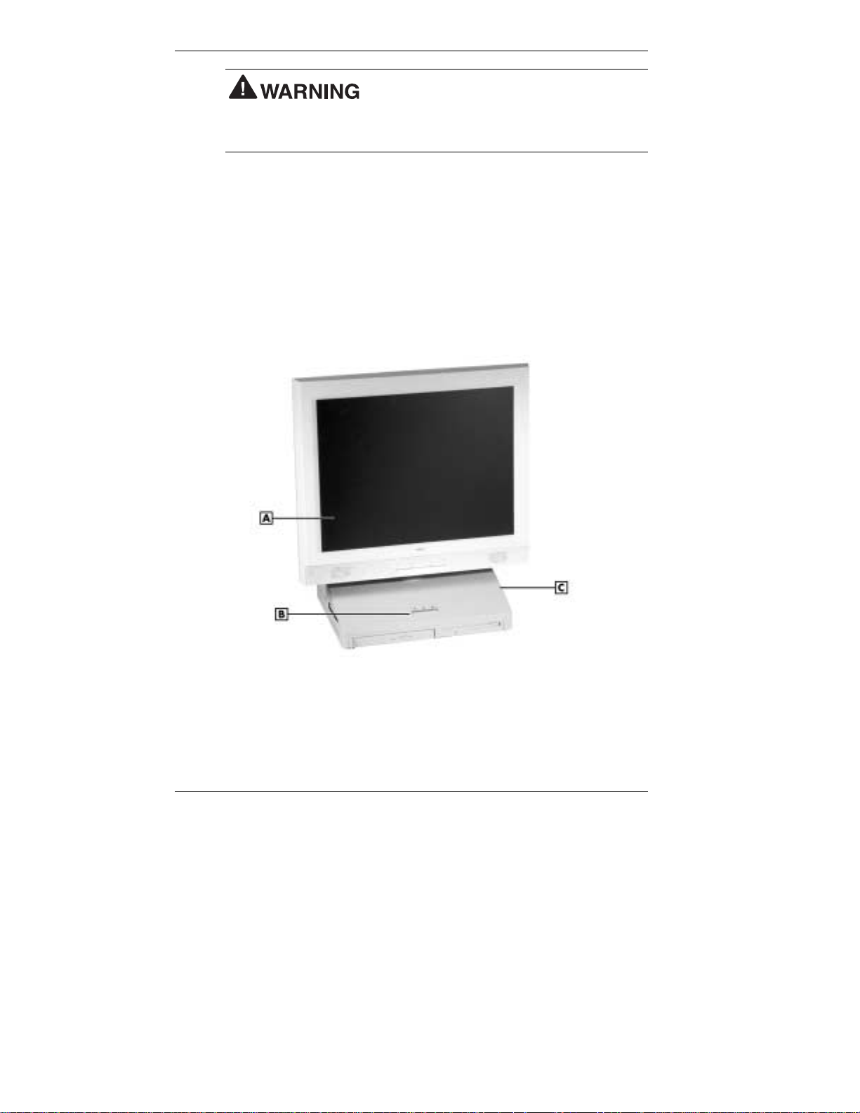
PowerMate 2000 system
A
– LCD Panel
B
– Power/Sleep Button
1-2 Reviewing System Features
C
– System Unit
Page 12
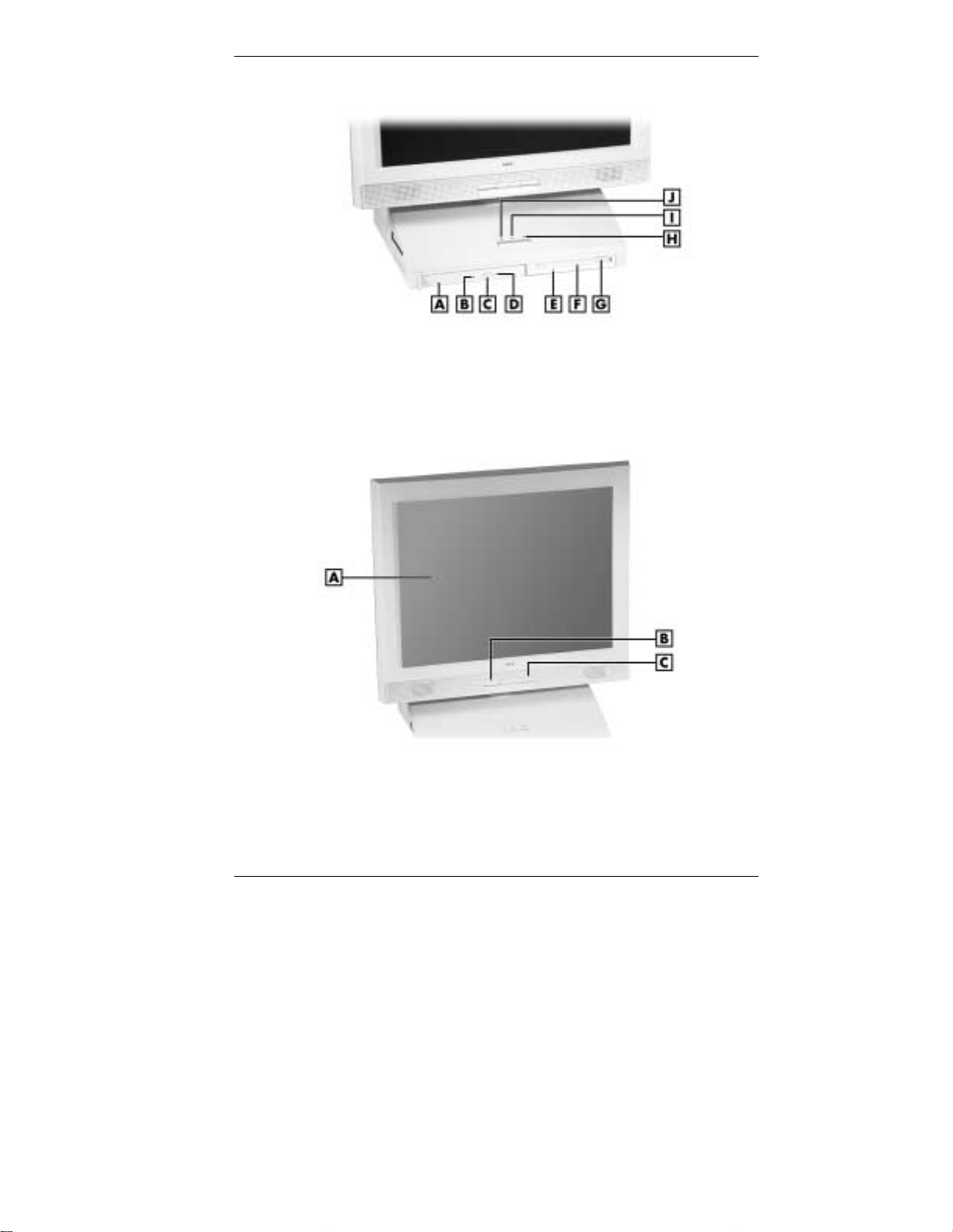
PowerMate 2000 system unit front features
A
– CD-ROM Drive
B
– CD-ROM Drive Lamp
C
– CD-ROM Disc Eject Button
D
– CD-ROM Disc Emergency Eject I – Power Lamp
E
– Dis kette D r ive Lamp
PowerMate 2000 LCD panel features
A
– LCD Panel
B
– Decrease Brightness Level Button
F
– Diskette Drive
G
– Diskette Eject Button
H
– Hard Drive Lamp
J
– Sleep Lamp
C
– Increase Brightness Le vel Button
Reviewing System Features 1-3
Page 13
System Controls and Lamps
System unit controls include a power/sleep button, power lamp, sleep
lamp, and hard drive activity lamp.
Power /sleep button
To turn system unit and LCD panel power on, pr ess th e power/sle ep
button. To turn off pow er, press the butt on an d h ol d in pla ce for four
or more seconds before releasing.
Do not turn off the system power until you have
closed all applications and the Microsoft® Windows® operating system or
you might lose data.
To su s pen d s ys tem unit and LCD pa nel opera t ion, press the
power/sleep button an d r elease within three seconds . Th is places the
system in a power savings mode. Use this feature if you plan to be
away from your system for more than 15 min u tes. If the s ystem does
not go into a power saving mode and shuts down, check the power
management setting (see “Power-Saving Operation” in Chapter 2).
Do not hold the button in any longer than three
seconds or you will turn off the system and possibly lose data.
Press any key or move the mouse to resume s ystem opera tion at the
point where you stopped it.
Power an d sleep lam p s
The power lamp indicates if system power is on or off. The sleep lamp
let s you know if the system is oper ating in a p ower-s aving mod e .
A stead y green power lamp indi cates that the power is on to all system
components. An am ber sleep lamp indicates tha t the system i s in sl eep
mode with full-power reduction.
Hard drive activity lamp
A flash ing green lamp indicates tha t the hard drive is acti ve and is
readin g or wri t i ng data.
Do not tur n off t he sy stem unles s absolutely
necessary while the hard drive lamp is flashing. To do so can damage
your hard drive or data.
1-4 Reviewing System Features
Page 14

LCD Panel
The syst em comes with an LCD panel that you can adjust up or d own and
side-to-side for a comfortable viewing position. The panel uses a 15-inch,
twisted nematic Thin Film Transistor (TFT) Super Video Graphics Array
(SVGA) color screen. The screen has a brightness of 200 candlepower
and a maximum resolution of 1024 x 768 pixels.
The LCD panel screen automatically turns on when you pr es s the system
power button. If you have an optional vid eo graphi cs arra y (VGA)
monit or attach ed to the system, the monit or can be turned on for
simultaneous viewing on the monitor and the LCD panel.
An increase brigh tness butt on and a d e c rea s e brightn ess button on the
panel allows you to increase or decrease the brightness of the display. The
buttons provide eight levels of brightness. The default brightness is
maximum.
Note
outlet changes any new brightness setting to the maximum default
brightness.
Powering off the system or unplugging the system from the power
Diskette Drive
Use the diskette drive to copy data files to and from a diskette. You can
also use it as a bo otable drive for loading a nd starting pr ograms from a
diskette.
A flashing gr e en activit y l amp on t he front of the dr ive indicates that the
drive is reading or writing data.
Press the eject button to eject a disk ette.
data, do not turn off the system or remove a diskette while the diskette
drive busy lamp is flashing.
To p reven t dama ge to the di skette drive and
Reviewing System Features 1-5
Page 15

CD-ROM Drive
All systems come with a variable speed CD-ROM drive. Use the
CD-ROM drive to load and start programs from a compact disc (CD).
You can al s o u se the CD- ROM drive to play your aud io CDs.
The CD-ROM drive operates at differ en t speeds d ep ending on wh ether
the CD you are using contain s data or music. This all ows you to get your
data faster and to see smoother animation and video.
A flashing amber activity lamp on the front of the drive indicates that the
drive is reading data. Press the tray button to open or close the CD-ROM
tray for loading or unloading a CD. An emergency eject feature allows
you to open the tray in c ase of a power or software ma lfunc tion .
Optional Combo Drive
Some systems might come with an optional variable-speed combo drive
in place of the CD-ROM drive. Th e com bo drive provides the functions of
a CD-RW drive and a DVD-ROM drive in one unit.
Use th e combo drive to load and start programs from C D s or to play audio
CDs while you work or relax. With the Mi crosoft Windows 9 8 Sec ond
Edition (SE) or Windows 2000 operating system, you can play full-length
CD-I movies and play movies in DVD format (DVD is not suppor t ed
under the Windows NT
and audio CDs and to write information to a recordable or re-recordable
CD.
®
operat ing system). Use the dr ive to crea te data
Speakers
The syst em has two 1-watt ster eo sp eaker s mou n ted inside the base of the
LCD pan el. Speaker volume is control led by the volume cont r ol on the
right side of the system unit. Volume can also be controlled through the
Microsoft Windows sound software.
1-6 Reviewing System Features
Page 16
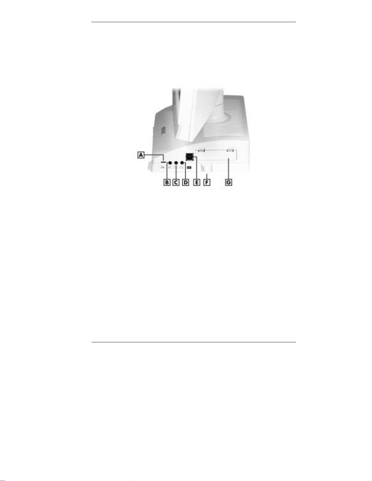
Right Side Features
The following fig ur e shows the features on the right side of the system
unit. Brief descriptions of the features follow the figure.
PowerMate 2000 right side features
A
– Volume Control
B
– Headphone Jack
C
– Line-In Jack
D
– Microphone-In Jack
Volume Control
Use the volume control to adjust th e volume of the system’s built-in
speakers or opt ional hea dphone set. Th e s p eakers are located in the base
of the LCD panel.
You can also use the Windows sound software. To bring up the Windows
volume control, double click the speaker icon on the taskbar (next to the
system cl ock). Use t he software to bal ance the sound between the left an d
right speakers.
E
– USB Connectors (2)
F
– Cable Lock Bracket
G
– Hard Drive Access Panel
Reviewing System Features 1-7
Page 17

Audio Conne ctors
Your system unit has the following audio connectors:
Micr ophone-in jack
Use thi s jack to connect a micr ophone for r ecording au di o information
in your data files.
Line-in jack
Use thi s jack to connect a stereo a u d io device such as a ster eo
amplifier or a c assette for playback or re cordi ng.
Headphone jack
Use thi s jack to connect an opti on al headphone set. Pluggin g in the
headphone set disa bles the built-in system speakers.
Universal Serial Bus Ports
The system unit comes with two USB ports. The ports allow you to easily
and conveniently add Plug and Play USB devices without opening up the
system. You simply plug the USB device into a port. You can connect up
to 127 USB devices including a keyboard, mouse, monitor, printer,
scanner, or speaker set.
Hard Drive
The syst em comes with an enhanced intelligent d evice elect ronics (EIDE)
hard dr ive. The dri ve fea tures u ltra direct memory acc es s (DMA) 66
techn ology for fas t data transfer. Th e dr ive also features S elf-Moni toring,
Analysis and Reporting (SMART
®
) technology.
The dri ve i s located inside the system unit, behind th e h ard drive a ccess
panel on the right side.
Hard disk activity is indicated by a flashing green lamp on the front of the
system unit.
Anti-theft Bracket
Your system comes with an anti-theft bracket installed on the right side of
the syst em unit, bel o w t he hard dri ve a cces s pan el. Secur e your mouse
and keyboa rd cables withi n the anti-theft bra c ket to make it di fficult to
remove t he cables from the system .
1-8 Reviewing System Features
Page 18
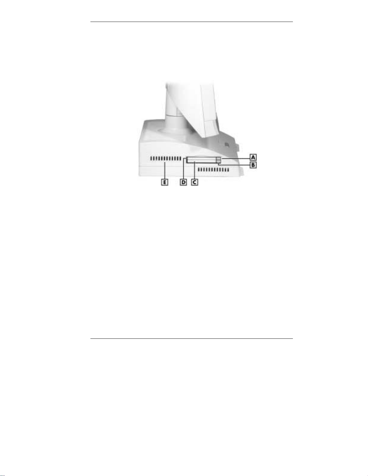
Left Side Features
The foll o wi ng fig ure shows the fea tures on the left si d e of the system un it.
Brief descriptions of the features follow the figure.
PowerMate 2000 left side features
A
– Slot 1 Card Eject Button
B
– Slot 2 Card Eject Button
C
– PC Card Slot 2
PC Card Slots
Your system has two PC Card slots that support 32-bit CardBus
techn ology and 1 6 -bit PC Card tech nolog y. The CardBu s technol og y
provides up to 132 MB/second of bandwidth.
The card slots support two Type II PC Cards or one Type III PC Card in
the bottom slot for extending the system’s capabilities. Each type of PC
Card has a different function. Using the PC Card slots, you can add a
number of functions to the system with a variety of cards, including a
modem, memory, and Small Computer System Interface (SCSI).
A PC Card is inserted into a PC Card slot similar to inserting a diskette in
a diskette drive. Press the eject button to eject a PC Card. Removable slot
cover s keep forei g n matter out of the slot s when PC Card s are not used.
D
– PC Card Slot 1
E
– Fan (behind vent)
Reviewing System Features 1-9
Page 19
System Unit Fans
The system’s t wo fans c ool sys tem unit c omponent s to preve nt them from
overheatin g. Keep the area near th e fan vents clear for proper ventilation.
The fan s are inside the system unit, and th e vents are on th e left sid e an d
top of the unit.
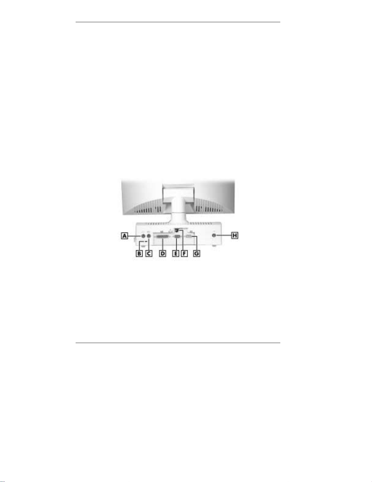
Rear Features
On the r ear of the system unit, you’l l find connectors for your mouse,
keyboard, printer, serial device, monitor, and LAN (or optional modem).
You’ll als o find a Ken sington
These featur es are described in th e fol lowing s ections .
Depending on your s ystem’s configuration, an optional mounting bracket
might be install ed at the rear of the system unit. Use the bracket to secure
the syst em to a solid object (for ex ample, to a wall).
PowerMate 2000 rear features
®
lock slot an d a DC power connector.
A
– PS/2 Mouse Port
B
– Kensington Lock Slot
C
– PS/2 Keyboard Port
D
– Pri nter Por t
1-10 Reviewing System Features
E
– Serial Port
F
– LAN (or optional modem) Connector
G
– VGA Connector
H
– DC Power Connector
Page 20

PS/2 Mouse Port
The system unit comes with a mouse port that supports a
personal system/2
mini D I N connector .
Use this port to connect the PS/2 mouse shipped with your system.
®
-compatible (PS/2-compatible) mouse with a 6-pin
Kensingt on Lock Slot
The lock slot on th e rear of t he system a ccep ts a Ken sington Secu rity
Stan dard conn ector or other lockin g device.
Use t his s lot and a locking device to secu re your s ystem to an immova ble
object.
PS/2 Keyboard Po rt
Your system unit com es with a ke yboard port that supports a standard
PS/2 101-key or 104-key keyboard with a 6-pin mini DIN connector.
Use t his port t o conne ct th e PS/2 keyboard shippe d with your s ystem .
Printer Port
Use thi s p or t to connect a parallel printer with a 25-pin connector to the
system unit. The port is an enhanced capabilities port (ECP). It also
supports enhanced parallel port (EPP), bi-directional, and uni-directional
protocols.
Serial Port
Atta ch a serial devi ce wi t h a 9-pin con nector to th i s s er ial port. S er ial
devices incl ud e a p ointing device, serial printer, or a modem.
LAN Connector
Systems come with a M in i PCI local area networ k (LAN) board. Use th e
RJ-45 comp atibl e LA N con nector on the rear of the system to conn ect a
network cable to the internal 100Base-TX/10Base-T network board.
Reviewing System Features 1-11
Page 21

Optional Modem Connec tor
Some systems might come with an optional Mini PCI V.90 56K modem
boar d in pl ace of the LAN board. Use the modem connector on the rear of
the syst em to conn ect your telephone l ine to the system.
VGA Connector
The syst em unit com es with a VGA conn ector on the rear of th e system
unit.
Use thi s con nector t o connect an op tional NE C M ul tiSync
AccuSync™ monitor, or oth er VGA-compa t ible monitor with a 15-pin
conn ector. You can also atta ch a projector wi th a 15-pin connect or to this
connector.
The system supports simultaneous use of the LCD panel and an optional
monit or con nected to the VGA connector.
DC Power Connector
The syst em operat es with DC power supplied from the AC p ower adapt er .
The adapter plugs into an AC p ower s ource an d the DC power connector
at the r ear of the system unit. The AC power adapter uses a standard
115-Vac or 230-Vac grounded power source.
®
monitor, NEC
1-12 Reviewing System Features
Page 22
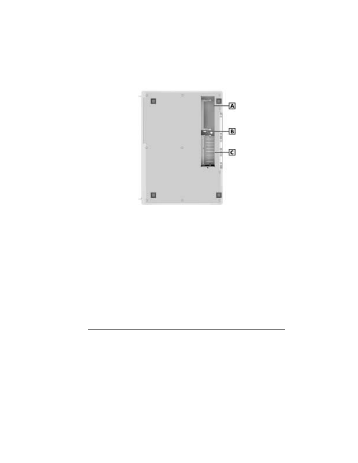
Bottom Features
A panel on t he bot tom of the system unit c overs the t wo memory
expan sion sockets and the password clear jumper. (See Ch apter 4,
“Adding Expansion Dev ices,” for information on removing the panel.)
PowerMate 2000 bottom features
A
– SO-DIMM Socket 1
B
– Password Clear Jumper
Memory Sockets
The system unit comes standard with one 128-MB small outline dualinline memory module (SO-DIMM) mounted in one of the system’s
memory sockets.
You can increase system memory up to a maximum of 512 MB by using
64-MB, 128-MB, and 256-MB modules (see “Adding Memory Modules”
in Chapter 4).
C
– SO-DIMM Socket 0
Reviewing System Features 1-13
Page 23

The modules use synchronous dynamic random access memory
(SDRAM). Memory allocation is controlled by Dynamic Video Memory
Technology (DVMT). With DVMT, total system memory is shared
between s ystem memory and video memory. For exampl e, with 128 MB
of total system memory, 112 MB might be allocated for system memory
and 16 MB for video memory, with actual memory use dependent on
video usage.
Password Clear Jumper
Use th e password cl ear jumper to clear your passwor d if you f orgot i t. To
clear and reset the passwor d, see “Jumper Settings” and “Securi ty Menu”
in Cha pt er 3.
Microdesktop Chassis
The NE C Microdeskt op chassis conform s to NEC’s Very-Small Form
Factor and Flat Panel Display Specification. The microdesktop h as the
following features:
small size chassis that is 85 percent smaller and correspondingly
lighter than traditional desktops
15-inch LCD panel with 1024 x 768 pixel maximum resolution, eight
levels of d isplay brigh tness , hor i zont al viewing angl e of 60 de grees
from cen ter to r ight or left s ide of p a nel , ve rtical viewing ang le of 40
degrees from center of panel and upwards, and 50 degrees from center
of panel and downwards
80-watt power supply built into the AC power adapter
bracket (optional) for securing the system to a wall or other solid
object.
1-14 Reviewing System Features
Page 24

System Overview
The syst em hardware and softwa re deliver the performan ce and
technologies needed for all your ch allenging tasks today and int o the
future.
Hardware
The PowerMate 2000 system includes the following hardware features:
PC99 Compliance
All the hardware in the system is certified by Microsoft to be PC99
compliant.
Processor
The syst em comes with an Intel
pr oc essor (133-MHz or hi gher front side bu s ). Th e processor is a fas t,
powerful processor that lends itself to computational, graphical, and
networking tasks.
Audio
The system board comes with an integr ated audi o s ubsys tem. The
audio chipset gives you a surround sound system for
three-dim ensi ona l soun d effects. It also provides wavetable synthesi s.
Flasha ble ROM BIOS
The system’s ROM BIOS features system setu p con fig uration, plug
and play support, and flash support for economical BIOS upgrades.
®
Pentium® III 933-MHz or higher
System and Video Mem ory
Your system comes standar d with 12 8 MB of non-ECC PC100
SDRAM and supports up to 512 MB of total system memory. The
memory uses DVMT technology which allows system memory to be
shared with video memor y.
AGP Graphics
The syst em comes with a 4-MB Dir ect Acceler ated Gra ph ics Port
(AGP) in tegrated on the system b oard. Direct AGP enhances graphics
performance, particularly for 3-D applications.
Power Management Options
Power management options extend the life of your LCD panel,
conser ve energ y, and reduce p ower costs.
Reviewing System Features 1-15
Page 25

Software
NEC provides a variety of software applications and hardware utilities
with your system to let you take advantage of your hardware capabilities.
Preloaded Software
Your system comes preloaded with the Microsoft Windows 98 SE
operating system or with the Windows 2000/Windows NT
system.
If you have a Windows 2000/Windows NT configuration, you must
choose t he operat ing system you wa nt to loa d . Th e op erating s ystem you
choose is your only ope rat i ng system and i s the one that the NEC Produ c t
Recovery program restores.
The syst em also comes preloa d ed wi th the Intel Process or Serial Number
Control Utility. Use this utility to enable or disable the reading of the Intel
Pent iu m I II processor serial number.
NEC Product Recovery CD
Your system comes with an NEC Product Recovery CD. Should a
problem occur th at causes d ata loss or corrupti on , you can us e th e N EC
Product Recovery CD to restore the system to its original factor y stat e. A
system restore loads the operating system and the fact ory-supplied
softwa re that com es with th e system. See “NEC Product Recovery” in
Chapter 3 for information about using the restore options.
PowerMate Application and Driver CD
Use th e P ower M ate Appl ication an d Driver CD to in s tall NEC Com puters
pr ovided appl ication s, drive rs, a nd uti lities on your hard drive. Also u s e
the PowerMate A p pl ication and Driver CD to reinstall NEC Comp ut ers
supplied software. See “PowerMate Application and Driver CD” in
Chapter 3 for information about installing software from the CD.
4.0 operating
NEC Computers software available on the PowerMate Application and
Driver CD includes the following applications:
Microso ft Intern e t Expl orer Br owser
Internet Explorer provides a top-notch browser with preloaded links
for ea sy access to th e wor ld wide web. Also use Internet Ex p lorer to
acces s one of the ma ny new browse r-based utiliti e s .
1-16 Reviewing System Features
Page 26

Security
The system has hard wa re, software, and mechanical security features th at
offer pr otect ion a gain s t unaut horized acc e s s to your s ys tem and da t a. The
follo wing security featu res are a va ilable with the system.
Norton AntiVirus™ Software
Protect the system from viru ses by runn ing Norton’s virus scan
software.
Adobe® Acr obat® Reade r
Use th e Adob e Acrobat Rea d er to read an d print por table document
format (PDF) files found on the Internet and PDF documents included
with various software applications.
NEC INFO Center
Get quick access to comprehensive information about your system in
the on line NEC INFO C en ter. NEC IN F O mod u les inclu d e Tour,
User’s Gu id e, Quest ions, Solut ions, an d Services. S ee “NEC INFO
Center” in Chapter 3 for a description of the documentation and how
to use th e INFO Center .
Intel LANDesk® Client Manager
Use LANDesk software to track system information such as serial
number, BIOS version, memory capacity, disk capacity, expansion
board setting s, and applications. Use LANDesk software for remote
star ts from a server comput er using Wake- On LAN and remot e r ebo ot .
Password Secur ity
The BIOS Setup utility includes a feature that lets you set a user or
supe rvisor password, or both.
The user password control s booting of the system an d controls acces s
to the Setup Utility and the keyboar d. (User access to the BIO S S e tup
Utility is limited to a subset of all BIOS Setup parameters when a
supervisor passwor d has been set.)
The supervisor passwor d al l ows full access to the system and the
BIOS.
Reviewing System Features 1-17
Page 27

Security Lock Slot
The security lock slot on the rear of th e system accept s a Kensin gton
Security Stan d ar d connect or or other locking devi ce. Secur e the
locking device to the security lock slot and to an immovable object to
pr otect your s ystem from theft .
Anti-theft Bracket
The ant i-theft br acket can be used to secu re your mou s e and keyboard
cables. S ecu ring the cables in the brack et makes th em di ffi cu lt to
remove fr om th e system .
Hard Drive Security
Your system supports password protection for the hard drive. Hard
drive password protect ion restricts access to the dr ive if the drive is
removed and installed in an other sys tem. The s ystem does not prompt
for hard drive passwords while th e drive remains in the current
system.
The pa s s wor d s are written to the system BI OS and to th e hard drive t o
ensure that the password protection travel s wi th the hard drive in the
event it is moved to an ot her system . (See “Hard Drive Security” in
Chap ter 3 for addi tional in formation on using this feature.)
Wind ows Network Securit y
To learn more about the network security features available through
the Windows oper ating system , refer to your Windows docum entati on
or consu lt your system ad m i nistrat or.
1-18 Reviewing System Features
Page 28

Setting Up the System
Cable Connections
Startup
Shutdown
Power-Savi ng Op era tion
Syste m Care
More Informatio n
2
Page 29

This cha pter provid e s basic informa t ion for set tin g up and us i ng your
system ( refer t o th e Quick Setup poster for details) . Includ ed ar e cable
conn ections, s ystem star tup procedures, system shutdown procedu res, and
system ca re. The chapter also includ es a table showing where t o find
additional information about your system.
Cable Connections
After unpacking the system (save the carton) and positioning the system
in your work area, con nect the system components using the Quick Setup
poster and the following tips.
Use the icons on the rear and side of the system unit to identif y th e
USB, keyboard, mouse, LAN, modem (if installed), printer, monitor,
power, and audio connectors.
See your n e twork adm inist rat or for gu ideline s on configuring the
LAN.
Connect the system A C ad apter power cord to a surg e protector
(recom mended ) or a properly ground ed wall outlet and to th e DC
power connect or at the rear of the system unit.
NEC Computers recommends connecting the AC
adapter power cord to a surge protector to protect your system.
Startup
Press the power button to turn on the system unit and LCD panel. The
power l amp lights green to indicate that the system is on. The system
performs its Power-On Self-Test (POST) and several messages appear on
the screen indicatin g that the system is check ing its su bsystems.
Note
appears:
Setup Utility, immediately press
Chapter 3, “Configuring the System,” for information on using the BIOS
Setup.)
After a short delay, the Mi crosoft Windows oper ating s ystem s tart s up.
2-2 Setting Up the System
At t he bottom of t he NEC startup s creen, the following mes sage
Press F2 to enter BIOS Setup
F2
. If you want to enter the BIOS
whil e the start up scr een di spla ys. (See
Page 30
If a proble m occurs, a s eries of beep s might sound. I f t his h appen s
repeatedly after powering on, power off the system and go to Chapter 5,
“Solving Syst em Problems.” T he chapter provi des help ful hints for
solving system problems.
If the system displays a messag e indi cating that system settings have
changed, run the BIOS Setup Utility (see Chapter 3, “Configuring the
System”).
On systems with the Microsoft Windows 2000 operating system, enter
your pass word at th e l og-on box. On syst ems with the Microsoft
Windows NT 4.0 opera t i ng system, pre s s
do so. Enter your password at the log-on box.
Shutdown
Follow t hese step s to power off the system.
a system in sleep mode, save and close any open applications, exit
Windows, and power down the system.
1.
If the system is in sleep mode (sleep mode lamp amber), move the
mouse or press a key to ta k e it out of sleep mode (see “P o wer Savin g
Operation” in the next section).
Ctrl Al t Del
To prevent damage to system components, wake
when prompted to
2.
Save your work and exi t all open ap plications.
3.
Make sure that the hard drive, disk ette drive, and any oth er d rives are
not in us e. A lit device l amp indi cates that the device i s in use.
Wait until all open applications are saved and
closed before using the Windows operating system shut down procedure
in step 4.
Unless absolutely necessary, never power off the system if the system
sl eep lamp is amber ( s leep mode), if eith er the h ard drive lamp, disk ette
drive, or other device lamp is flashing, or if any applications are open.
Information on the device might be lost or damaged.
Setting Up the System 2-3
Page 31

4.
Start
Click
the computer
on the taskbar and click
, then click
Yes
or pr e s s
dependi ng on you r ope rating system.
If the system is configured with Windows 98 or Windows 2000,
the syst em shut s down automatically aft er a shor t interval.
If th e s ystem is confi g ured with Windows NT, perform a
Windows shut down, then power off the system by pressing and
holding in the power button for four seconds or longer.
Power-Saving Operation
If the system is running Windows 98 or Windows 2000, you can put it in
sleep mode (a power-saving state) by pressing and immediately releasing
the power butt on on th e front of th e system unit. The sleep mod e
conserves energy when you are going to be a way from your system for
more th an 15 minutes. If the system does n ot g o in to sleep m ode, check
that the sleep mode is enabled in power management. Click
Settings
Options
Power buttons
power button to enter the sleep mode. Avoid pressing and holding in the
power button longer than three seconds or you may turn off power and
possibly lose data from any open applications.
Control Pane l
, click
, double click
for Windows 2000), and click
drop -down m enu.
Tak e car e t o pres s and immediately releas e the
Shut Down
Enter
Powe r Ma n a gement (Power
Advanced
. Select
for shut down,
. Select
Shut down
Start
Standby
, point t o
in the
The syst em also goes into sl eep mode when it has been inact ive, if the
power management has been enabled, and an inactivity timeout has been
enabled. To see if power management is enabled, click
Settings
Options
Control Pane l
, click
for Windows 2000), click
settings.
When the system goes into sleep mode, it automatically saves data and
system statu s and then shu ts off power to all possible compon ents. Sleep
mode lets you save power without firs t s avin g your work.
An amber s leep lamp an d bl ank screen in d icates that the system is in sleep
mode. Press a key or move the mouse to resume system operation where
you left o ff.
2-4 Setting Up the System
, double click
Power Schemes
Start
, point to
Powe r Ma n a gement (Power
, and check the
Page 32

System Care
The system is a durable system built for dependable use. With protective
mea s ures a nd pr oper care, you can prevent problems and promote the
successful operation and long life span of the system.
Protecting Your System From Damage
There are several ways tha t you can prot ect the system from p ossible
damage. NEC Computers strongly recommends the following protective
measures.
Connect a surge s u ppressor bet w een the system and a grou nded wall
outlet. A surge suppressor protects the system from sudden transient
increases and decreases in electr ical power.
Be sure t o connect al l p eripher als, such as a printer , to the surge
suppressor. The surge protector should be the only device that you
plug into the wall outlet.
Avoid r ep eated power -on cycles. These subject the system
components to temperature variations and stress.
Discon nect the s ystem from telephon e an d power lines when an
electrical storm thr eatens. If you h ave a fax/modem, lightnin g can
travel in on the phone line and damag e both the fax/mod em an d the
system u n it. Ligh tn ing can also travel in on power lines and dam age
the LCD panel and system unit.
Except for USB devices, ensu re that syst em power is off before
conn ecting or disconnecting a cable; other wi s e d amage t o the s ystem
and its peripherals might occur. USB devices do not require powering
down the system wh en con necting or disconnecting a device.
Use your N orton virus scan prote ction soft ware reg ularl y t o protect
the system from viruses.
If you plan to load soft ware progr a ms other th a n the ones NEC
Computers ha s supplied on th e P owerMat e A pp licati on an d Dr iver
CD, NEC Computers strongly recommends that you take the
necessary steps, such a s backing up your system an d p er formin g virus
checks, to prot ect the system and your data.
Setting Up the System 2-5
Page 33

Position the system away from direct sunlight and extreme hot and
cold temperatures.
The recom mended op er ating environm en t is from 50°F to 95°F (10°C
to 35°C).
The recom mended non-opera ting environment (shippin g or storage) is
from 14°F to 158°F (-10°C to 70°C).
After turning off power, wait about five seconds for the hard drive to
spin down before you p ower on aga i n.
Be sure th at nothing is placed on top of th e system’s AC ada pt er and
power cord.
Preven t dust from en tering th e system by covering it when not in us e.
Keeping Your System in Good Condition
Maintain the condition of your system by periodically using the following
procedures.
For safety, power off and unplug your system
and any external devices before cleaning them.
Clean the outside of the system u n it and LCD panel (but n ot th e
screen) with a soft clean cl ot h.
Remove stubborn s tains with a cloth sli gh tly damp ened with a mild
detergent. N ever use a strong clean er or s ol vent on any part of the
system.
Clean the LCD panel screen with a soft, lin t-free cl ot h or a screen
wipe desi g ned for that purp ose. Specia l screen wip es are available
through your local computer dealer.
Keep food and liqu ids away from the system.
Peri odically clea n th e keyboa rd with a va cuum cleaner bru sh
atta ch ment and va cu um cleaner special ly designed for comp u ter use.
Do not use any liquid cleaners on the keyboard as they can damage the
keyboard.
If an object , such a s a pap er clip, falls into the k eyb oa rd, turn the
keyboard over and g entl y shake it.
2-6 Setting Up the System
Page 34

Moving or Shipping Your System
Use th es e s teps to pr epare the system for moving or shi p ping.
1.
Back up your files on the hard drive to diskettes, server hard drive, or
other backup devices.
Take precautions for st or ing and transporting storage media so that
they are not exposed to magnetic fiel d s or electri cal impuls es .
2.
Remove any dis kette from the di sket te dri ve . If you have a CD in the
drive, remove the CD.
3.
Remove any PC Cards from the car d slots on th e l e ft side of your
system u n it. In stall the slot cov ers.
4.
Wake up a s ystem in sleep m od e, save and close any open
appli cations , shut down the Windows operating system, and turn off
the syst em unit an d any external options connected to it.
5.
Unplug the system A C adapter p ower cord from the wal l ou t let or
surge suppressor and the AC adapt er from the system un it.
6.
Unplug any exte rnal options from the wall outl ets or s urge
suppressor, then disconnect them from the system unit.
7.
Pack the system comp onent s in the origin al shipping materials and
cartons. If th es e are not ava ilable, be sure to use ad eq uate packing
materials to protect the components.
Note
event that you need to ship the system back for repair.
Be sure to save the original shipping materials in the unlikely
To set up the system, follow the st eps on the PowerMate 2000 Quick
Setup poster that comes with the system.
Setting Up the System 2-7
Page 35

More Information
Once the system is up and running, we suggest that you do the following.
See “Setting Up a He al t hy Work E nvironment” in Appendix A.
Install applications provided by NEC Computers on the PowerMate
Application and Driver CD.
Install any of your own applications. See the documentation that
comes with the application.
See the following quick reference table to find information about using
your system.
Quick Reference to Information About Your System
Information Where to Find It
Accessing the world wide web Chapter 6
Adding expansion devices Chapter 4
Guidelines for using your system Appendix A
Installing the applications provided by
NEC Computers
Protecting the system from viruses Chapter 1
Setting a password Chapter 3
System specifications Appendix B
Taking care of the system “System Care” in Chapter 2
Troubleshooting tips Chapter 5
Using support services Chapter 6
Using the NEC INFO Center online
documentation
“PowerMate Application and Driver
CD” in Chapter 3
“NEC INFO Center” in Chapter 3
2-8 Setting Up the System
Page 36

Configuring the System
Configuration Tools and Utilities
BIOS Setup Utility
Hard Drive Security
FLASH Utility
NEC Customize Utility
PowerMate Application and Driver CD
NEC INFO Center
NEC Product Recovery CD
System Board Jumper Settings
3
Intel Processor Serial Number Control Utility
Page 37

This cha pter provid e s informa t ion on con figuri ng your syste m. The
chapter includes information on:
Phoenix® Technologies Ltd. BIOS Setup Utility for configuring your
system
hard drive secu rit y for password protection of th e i nter nal hard drive
FLASH Utility for BIOS updates
NEC Customize Utility for launching the Application and Driver CD
NEC INFO Center for quick access to information about your system
PowerMate Application and Driver CD for installing drivers and
software
NEC Product Recovery CD for restoring the operating system
jumper settings for clearing your password, should you forget it
Intel Processor Serial Number Control Utility for controlling the
readin g of the processor s erial numbe r.
See th e followin g ta bl e for a qui ck guide to the ut ilities, tools, or
procedures required for configuring the system. For detailed information
about these and other tools, s ee the secti ons follo wi ng the ta ble.
Configuration Tools and Utilities
The foll o wi ng tabl e lists ways you ca n confi gure the system, an d the
utility, tool, or procedure to use for the configuration.
Configuration Tools and Utilities
Configuration Method, Tool, or Utility
BIOS, updating FLASH Utility
Boot devices, determining BIOS Setup (Boot Menu)
Boot order, changing BIOS Setup (Boot Menu)
Clearing password Jumper Settings
Diskette drive, enabling BIOS Setup (Main Menu)
Driver s for NE C Comp uters har dware PowerMate Application and Dri ver CD
3-2 Configuring the System
Page 38

Configuration Tools and Utilities
Configuration Method, Tool, or Utility
Hard drive, reform at ting NEC Product Recovery CD
Har d drive, setti ng a pr e-delay BIOS Set up (Power M enu)
Inactivity timeout, setting BIOS Setup (Power Menu)
Keyboard options BIOS Setup (Main Menu)
Memory, checking BIOS Setup (Main Menu)
NEC INFO Center See “NEC INFO Center”
Operating system, restoring NEC Product Recovery CD
Parallel port, enabling, configuring BIOS Setup (Advanced Menu)
Pas sword, setting or clearing (user,
supervisor, or both)
Plug and Play, enabling BIOS Setup (Advanced Menu)
Power management, enabling,
configuring
Serial ports, enabling BIOS Setup (Advanced Menu)
SO-DIMM memory, checking BIOS Setup (Main Menu)
Software provided through NEC
Computers, insta lling
Sound, enabling BIOS Setup (Advanced Menu)
Time and date, setting BIOS Setup (Main Menu)
USB functions BIOS Setup (Advanced Menu)
Microsoft Windows 98 SE, Wi ndows
2000, or Windows NT operating
system, restoring
BIOS Setup (Security Menu)
Jumper settings
BIOS Setup (Power Menu)
NEC Product Recovery CD
NEC Product Recovery CD
Config ur in g t he Sy stem 3-3
Page 39

BIOS Setup Utility
The BIOS Setup Utility lets you configure the main components of your
system. The utility is r es ident in the system FLAS H memor y and does not
requ ire a diskette or an oper ating system p resent to run .
Your system shi p s from the fact ory with th e correct system parameters for
your c onfigurati on. Unless you add opti onal h a rdware, you do not need t o
run the BIOS Setup Utility to operate your system. However, you might
wish to run the BIOS Setup Utility to set features that customize your
system, such a s security feat ures.
NEC Computers recommends that you print out or write down your
curr en t BI O S S etup par ameter s and s tore the in formation in a safe pl ace.
This lets you restore your system to the current parameters if you need to
have th e C M O S battery r ep laced.
How to Start Setup
To start the BIOS Setup Utility, follow these steps.
1.
Turn on or reboot the system .
2.
F2
Press
at the NE C startup scr een.
You have about fi ve sec onds to pre s s F2.
Setup’s Main Menu window appear s.
How to Use Setup
The Setup utility has a Main Menu window and six top-level menus with
submen us. The menu bar at the t op of the Main Menu window lists the
following top-level menus.
Main Use the Main M en u for basi c s ystem configurat ion. For
example, select Main to set th e system date, set disk et t e and hard disk
parameters, check memory parameters, or set the processor serial
number feature.
Advanced Use the Ad vanced Menu to configure the system for
Plug an d Play, PCI, cache memor y, I /O device, large disk acces s , local
bus IDE ad apter , quick boot , sound, DMI event log ging, and preboot
management.
3-4 Configuring the System
Page 40

Security Use this menu to set User and Supervisor Passwords,
security mode, pa s sword on boot, network boot, viru s check, and
system backup reminder.
Power — Use the Power Menu to set power management parameters
such as power savings, auto suspend timeout, hard disk timeout,
sys tem switch, resu me on mode m r ing, resume on time, and resume
time.
Boot — Use thi s menu t o s e t boot options, including restore on
ac/ power loss , power managem e nt, se t boot se quence, and a s s i gn
drive letters to removable devices.
Exit Exits the Setup Utility with various save or discard options.
Use the keys listed in the legend bar on the bottom of the Setup Menu to
make the selections or exit the current menu. The following table
describes the legend keys.
Setup Key Functions
Key Function
F1 Prov id es help for the pa rameter field
being displayed.
Esc Exits th e menu .
Up or down arrow keys Moves cursor up and down for item
selection.
Left or right arrow keys Selects next menu.
-/+ keys Changes values.
Enter Executes a command or selects
submenu.
F9 Loads the default configuration values
for the current menu.
F10 Saves the current v alues and exi ts
Setup.
Config ur in g t he Sy stem 3-5
Page 41

To select one of the six menus fr om the menu bar, u s e th e left and ri ght
arrow ke ys. Use the up or down arrow keys to sele ct an it em under the
menu.
Menu items preceded b y a > contain a submenu of selectable fi elds for
setting system parameters. Display a submenu by using the up or down
arrow keys to move the cursor to the desired submenu, then press
Enter
An Item S p ecific Help window on the right side of each menu displa ys
the help text for the curr en tly selected Setup opt ion. It updates as the
cursor moves to each new field.
.
Pressing
describes the legend keys and their functions.
Press
The following subsections describe the six top level menus and their
submenus.
Main Menu
Ch oos e the Main Menu by selectin g M a in in the leg e nd bar on the M a in
Menu screen. Other Main Menu opti on s are availa ble by selecting
submenus.
Use th e arrow keys to select one of the Main Men u op tions and pr ess
Enter
Explan ations of each Main Men u item are in the following tabl e.
can cause your syste m to malfunction.
Note
drive and a CD-ROM drive. The actual settings on your menu screens
depend upon the hardware installed in your system.
F1
on any menu brings up the General Help window that
Esc
to exit th e current wind ow.
to select a submenu. I t ems with gra yed-out tex t are not ava ilable.
Setting items on this menu to incorrect values
The followi ng menu inf or mation is typical for a syst em with a har d
3-6 Configuring the System
Page 42

Main Menu Items
Menu Item Settings (default is bold)
System Time Set system time in this field. Press
Enter
to move between hour, minute, and
second fields.
Example: 09:30:50
System Date Set system date in this field. Press
Enter
to move between month, date, and
year fields.
Example:
04/26/2001
Language
Legacy Diskette A Disabled
English
Selects the display language for the BIOS.
360 KB 5 1/4”
1.2 MB 5 1/4”
720 KB 3 1/2”
1.44/1.25 MB 3 1/2”
2.88 MB 3 1/2”
Selects the disk et te drive type.
(US), Japanese
Tab
Tab
or
or
Config ur in g t he Sy stem 3-7
Page 43

Main Menu Items
Menu Item Settings (default is bold)
Primary IDE Master
Primary IDE Slave
Secondary IDE Master
Secondary IDE Slave
xxxxx MB
None
CD-ROM
None
Note: The following setting information
applies to the primary and secondary master
and slave devices.
Each device menu item displays the hard
drive or CD-ROM identifier if a device is
installed.
If you install a hard drive th at does not featu re
auto IDE type detection or your IDE hard
drive was formatted on another system with
parameters diff erent from those reported by
the drive, en ter a parameter for each of t he
fields in the device submenu.
Bring up a device subm enu by pr essi ng
Enter
. The submenus include Type, CHS
Format, and LBA Format. Each submenu and
its fields are described next.
3-8 Configuring the System
Page 44

Main Menu Items
Menu Item Settings (default is bold)
Type User,
Removable, Other ATAPI
When set to Auto, the values for Cylinders,
Heads, Sectors, Total Sectors, and Maximum
Capacity are displayed but are read only.
When set to Auto, the BIOS detects what the
dri ve is capable of, not the trans lati on
mechani sm that was used t o format the drive.
If a drive is run in a mode other than the
mode in which it was partitioned and
formatted, unpredictable results might occur,
including data loss.
When set to None, informs the system to
ignore this drive.
When set to CD-ROM, IDE/ATAPI
Removable, or Other ATAPI, allows the
manual entry for multi-sector transfers, LBA
mode control, 32-bit I/O transfer mode, ultra
DMA mode, and SMART monitor.
When set to User, allows t he ma nual en try of
all the following fields.
CHS Format
Auto,
None, CD-ROM, IDE/ATAPI
(label field only)
Cylinders When Type is Auto, value in the Cylinders
field is auto-detected and field is read only.
Heads When Type is Auto, valu e in Hea ds field i s
auto-detected and field is read only.
Sectors When Typ e is Auto, va lue i n Sect ors field is
auto-detected and field is read only.
Maximum Capacity xxxx MB
LBA Format
Total Sectors xxxxxxxx total sectors
Maximum Capacity xxxxx MB
(lab el field o nly)
Config ur in g t he Sy stem 3-9
Page 45

Main Menu Items
Menu Item Settings (default is bold)
Mul ti-Sector Transfers Disabled, 2, 4, 8, 16 s ectors
Determines t he number of sectors per block
for multi-sector transfers.
When Typ e is Auto, va lue i n M ulti-Sector
Transfers field is auto-detected and field is
read only.
LBA Mode Control
32-Bit I/O
Transfer Mode Standard, Fast PIO1, Fast PIO2, Fast PIO3,
Ultra DMA Mode Disabled, Mode 0, Mode 1, Mode 2
Enabled
When Ena bled is select ed, it c auses logical
block addressing to be used in place of
cylinders, heads, and sectors.
When Typ e is se t to Auto, the value in the
LBA Mode field is auto-detected and the field
is read only.
Disabled
When Enabled, allows 32-bit data transfers.
Fast PIO4, PIO3/DMA1, PIO4/DMA2
Selects the method for moving data to and
from the drive.
When Typ e is se t to Auto, the value in the
field is aut o-detect ed and the field i s read
only.
Selects the Ultra DMA Mode for moving data
to and from the drive. Autotype the drive to
select the optimum transfer mode.
, Di sabl ed
, Enabled
3-10 Configuring the System
When Typ e is se t to Auto, the value in the
field is aut o-detect ed and the field i s read
only.
Page 46

Main Menu Items
Menu Item Settings (default is bold)
Keyboard Features Press
parameters.
Numlock
Key Click
Keyboard auto-repeat rate
Keyboard auto-repeat delay 1/4 sec,
Legacy USB Support Disabled,
USB Packet Size 8,
Boot-Time Diagnostics Screen
Auto
Selects the p ower- on st ate for Numlock .
Disabled
Enables or disables key click.
30/sec
13.3/sec, 10/sec, 6/sec, 2/sec
Selects key repeat rate.
Selects delay before key repeat.
Disables or enables legacy USB support.
64
Selects data packet size for BIOS at first
detection of USB devices.
Disabled
Enter
to check or change keyboard
, On, Off
, Enabled
, 26.7/sec, 21.8/sec, 18.5/sec,
1/2 sec
, 3/4 sec, 1 sec
Enabled
, Enabled
Selecting Enabled displays the diagnostic
screen during boot.
System Memory Displays amount of conventional memory
detected during boot.
This field is read-only and cannot be changed
from BIOS Setu p .
Exampl e: 640 K B
Configuring the System 3-11
Page 47

Main Menu Items
Menu Item Settings (default is bold)
Extended Memory Displays amount of extended memory
detected during boot.
This field is read-only and cannot be changed
from BIOS Setu p .
Example: 129024 KB
BIOS Revision Displays the BIOS revision number.
This field is read-only and cannot be changed
from the BIOS Setup.
Example: 183A0800
Processor Serial Number
Advanced Menu
Choose t he Advan ced Menu by selectin g Ad vanced in the legend bar on
the Main Menu scr een . O ther Advanced Menu options are available by
selecting submenus.
Use th e arrow keys to sele ct one of the Advanced Menu opt ions and press
Enter
to select a submenu. I t ems with gra yed-out tex t are not ava ilable.
Explan ations of each Advanced Menu item are in th e fol lowing table.
can cause your syste m to malfunction.
Disabled
Controls detection of the processor serial
number.
Setting items on this menu to incorrect values
, Enabled
3-12 Configuring the System
Page 48

Advanced Menu
Menu Item Settings (default is bold)
Plug and Play OS No,
Reset Configuration Data
PCI Configuration Press
PCI IRQ Line 1 = 10
PCI IRQ Line 2 = 5
PCI IRQ Line 3 = 10
PCI IRQ Line 4 = 5
Cache Memory Press
Memory C ach e Disabled,
Yes
Select Yes if you are booting a Plug and
Play capable operating system.
Select No if you want the BIOS to configure
non-boot devices.
No
, Yes
Select Yes if you want to clear the Extended
Sys tem Co nfi guration Data (ESCD ) area.
submenus.
Disabl ed, Auto Select , 3, 4, 5, 7, 9, 10, 1 1,
12, 14, 15
Use Auto Selec t if there are no ISA or EISA
devices installed on the system.
Select an IRQ (3-15) if installing a PCI
device requiring an IRQ and if the IRQ is not
already in use by ISA or EISA devices.
submenus.
Enter
to access the following
Enter
to access the following
Enabled
Sets the state of the memo r y cac he.
Cache System BIOS Area Uncached,
Controls caching of system BIOS area.
Cache Video BIOS Area Uncached,
Controls caching of system video BIOS
area.
Write Protect
Write Protect
Configuring the System 3-13
Page 49

Advanced Menu
Menu Item Settings (default is bold)
Cache Base 0-512K Uncached, Write Through, Write Protect,
Write Back
Controls caching of 512K base memory.
Cache Base 512-640K Uncached, Write Through, Write Protect,
Write Back
Controls caching of 512K-640K base
memory.
Cache Extended Memory
Area
Cache C800-CBFF
Cache CC00-CFFF
Cache D000-D3FF
Cache D400-D7FF
Cache D800-DBFF
Cache DC00-DFFF
Uncached, Write Through, Write Protect,
Write Back
Controls caching of system memory above
one MB.
Disabled
Write Back
Setting at Di sabl ed pro hibits ca chin g.
Setting at Write Through permits writes to be
cached and sent to main memory at once.
Setting at Write Protect c auses t he BIOS to
ignore writes.
Setting at Write Back permits write caching
but delays sending data to main memory
until necessary.
, Write Through, Write Protect,
3-14 Configuring the System
Page 50

Advanced Menu
Menu Item Settings (default is bold)
I/O Device Configuration Press
submenus.
Serial Port A Disabled,
Setting at Enabled allows the user to
con figure the por t .
Setting at Auto enables the BIOS or
operating sy stem t o conf igure the port.
Base I/O Address
Interrupt IRQ3,
Parallel Port Disabled,
Mode Output Only,
3F8
, 2F8, 3E8, 2E8
Selects the base I/O address for serial
port A.
Selects the IRQ for serial port A.
Setting at Enabled allows the user to
con figure the por t .
Setting at Auto enables the BIOS or
operating sy stem t o conf igure the port.
Enter
to access the following
Enabled
IRQ4
Enabled
, Auto
, Auto
Bi-directional
, ECP
Selects parallel port mode.
Base I/O Address
Interrupt IRQ5,
378
, 278, 3BC
Selects the base I/O address for the LPT
port.
Selects the IRQ for the LPT port.
IRQ7
Configuring the System 3-15
Page 51

Advanced Menu
Menu Item Settings (default is bold)
Floppy Disk Controller Disabled,
Setting at Enabled allows the user to
con figure the control ler.
Setting at Auto enables the BIOS or
operating sy stem t o conf igure the controller.
Base I/O Address
Large Disk Access Mode Other,
Local Bus IDE Adapter Disabled, Primary, Secondary,
QuickBoot Mode Disabled,
Primary
Sets the base I/O address for the controller.
Select DOS if using DOS operating system.
Select Other if using another operating
system such as UNIX or Novell NetWare.
Enables the integrated local bus IDE
adapter.
When Enabled, the BIOS does not test
system memory above 1 MB or wait for
ready signals, allowing a quick boot.
Enabled
, Secondary
DOS
Enabled
, Auto
Both
Sound
DMI Event Logging Press
Event Log Capacity Status only.
Event Log Validity Status only.
View DMI E vent L og Stat us only , press
Enabled
Select Disabled to turn off onboard sound.
Enter
submenus.
3-16 Configuring the System
, Di sabl ed
to access the following
Enter
to view.
Page 52

Advanced Menu
Menu Item Settings (default is bold)
Clear All DMI Event Logs
Event Logging
Mark DMI Events As Read Press
LANDesk ® Service Disabled,
Preboot Management
No
, Yes
Selecting N o preven ts clearing o ut the
DIMM event lo gs.
Enabled
Selecting Enabled permits logging of DMI
events.
Events as read?”
Select Enabled to enable the onboard
LANDesk.
Disabled
Select Enabled to enable the Preboot
Management function.
Security Menu
Choose the Security Menu by selecting Security in the legend bar on the
Main Menu screen . Other Secur ity Menu opt ions are ava ilable by
selecting submenus.
, Di sabl ed
Enter
Enabled
, Enabled
. Select
Yes
or No to “Mark all
Use th e arrow keys to sele ct one of the Securi ty Menu options and pres s
Enter
to select a submenu. I t ems with gra yed-out tex t are not ava ilable.
Explanations of each Security Menu item are in the following table.
Configuring the System 3-17
Page 53

Security M enu It ems
Menu Item Settings (default is bold)
Supervisor Password Is
User Pas sword Is
Set Supervisor Password Press
Set User Password Press
Clear
Status only, user cannot modify. Supervisor
password controls access to the BIOS Setup
Utility.
Clear
Status only, user cannot modify. User
password controls access to the system at
boot.
Use this field to set or change the supervisor
password. Press
box where the password can be entered and
confirmed.
Use this field to set or change the user
password. Press
box where the password can be entered and
confirmed.
, Set
, Set
Enter
Enter
to access.
Enter
to access.
Enter
to bring up a dialog
to bring up a dialog
3-18 Configuring the System
Page 54

Security M enu It ems
Menu Item Settings (default is bold)
Security Mode Press
Use this mode to select
SmartCard, or Finger P rint. Pr ess
open the selected field.
Use the Smart Card field to as sign a ccess t o
the SmartCard Reader by the supervisor
and/or user. Press
SmartCard Reader dialog box for setting up
SmartCard security.
The Assign Su pervisor SmartCar d f ield
controls Supervisor access to the BIOS
Setup utility and the system. A PIN number
controls access.
The Assign Us er SmartCa rd fi eld co ntrols
user access to the system at boot. A PIN
number controls access .
Password on Boot
Fixed Disk Boot Sector
Disabled
When Enabled, requires password entry
before boot. System remains in secure
mode until password is entered.
Normal
Enter
to access the Security Mode.
Password
Enter
to bring up the
, Enabled
, Write Protect
(default),
Enter
to
Diskette Access
Write Protect protects the boot sector on the
hard disk from viruses.
Supervisor
Controls access to the diskette drive.
, User
Configuring the System 3-19
Page 55

Security M enu It ems
Menu Item Settings (default is bold)
Network Boot Setting Press
Keyboard/Mouse Lock Disabled,
Select Enabled to lock the keyboard and
mouse when remote booting.
Virus Check Reminder
System Backup Reminder
Assign HDD Password Press
Disabled
Displays reminder message at bootup.
Message is daily, every Monday, or first of
every month.
Disabled
Displays reminder message at bootup.
Message is daily, every Monday, or first of
every month.
Password Mode.
Controls access to the system’s hard drive
by assigning master and user passwords.
See “Hard Drive Securit y” later in this
chapter for information and procedures for
using the HDD password mode.
CAUTION
are set on a hard drive, they can never be
removed. If the master password is forgotten
and the hard drive is installed in another
system, data cannot be accessed on the
hard drive.
Enter
to access.
Enabled
, Daily, W eekly, Mo nt h ly
, Daily, W eekly, Mo nt h ly
Enter
to access the Assign HDD
: If the master and user password
Primary Master HDD
Password
3-20 Configuring the System
Once these passwords are set, NEC
Computers Inc. has no capacity to
remove them.
Disabled
Indicates state of master HDD password.
, Enabled
Page 56

Power Menu
Choose t he Power Menu by select ing Power in the legend bar on the Main
Menu screen. Other Power Menu options are available by selecting
submenus.
Use th e arrow keys to select one of the Power Menu opti ons and press
Enter
to select a submenu. I t ems with gra yed-out tex t are not ava ilable.
Explan ations of ea ch Power Menu item are in the followi ng tabl e.
Note
Windows 98 or Windows 2000 operating sys tem.
Power manage ment is only supported in systems running the
Power Menu Settings
Menu Item Settings (default is bold)
Power Savings Disabled,
Savings, Maximum Performance
Disabl ed set t ing turns off Power
Management.
Maximum Power Savings setting conserves
the grea test amou nt of power.
Maximum Performance setting conserves
power but allows best system performance.
Cus tomized s etting allows t he user to m odify
the Auto Suspend Timeout and Hard Disk
Timeo ut field s .
Auto Suspend Timeout
Off
Spec ifies the amo unt of t ime the system i s in
standby before entering the sleep mode.
Customized
, 5, 10, 15, 20, 30, 40, 60 minutes
, Maximum Power
Hard Disk Timeout
Disabled
1, 2, 4, 6, 8, 10, 15 minutes
Specifies the amount of time the hard drive
needs to be inactive before it is turned off.
, 10, 15, 30, 45 seconds
Configuring the System 3-21
Page 57

Power Menu Settings
Menu Item Settings (default is bold)
System Switch Sleep Button,
Select Power Button to turn the system on
or off.
Resume On Modem Ring
Resu me On Time
Resume Time 00: 00:00
Off
, On
Setting to On allows the system to wake up
when an incoming call is detected on the
modem (if installed).
Off,
On
Setting to On allows the user to set the
Resume Time field to a time when the
system is to wake up.
When Resume on Time is set to On, the
user can specify the time the system is to
wake up.
Boot Menu
Ch oos e the Boot Menu by selectin g Boot in the le gend bar on the Main
Menu s cr een . Other Boot M enu opti ons are avail able by selecting
submenus.
Powe r But ton
Use th e arrow keys to select one of the Boot Men u op tions a n d pres s
Enter
to select a submenu. I t ems with gra yed-out tex t are not ava ilable.
Explan ations of each Boot Men u item are in the followin g table.
3-22 Configuring the System
Page 58

Boot Menu Settings
Menu Item Settings (default is bold)
Restore On AC/Power Loss
On PME
1 through 4 Sets the bootable device order.
Hard Drive Press
Power Off
Power Of f setting keeps power off until
power button is pressed.
Las t State setting res t ores the previ ous state
before power loss occurred.
Power On setting restores power to the
system.
Stay Off
Controls how system responds to a PCI
Power Management Enabled wake-up.
Use the up or down arrow to select a device,
then press th e + or
up or down the list.
System attempts to boot from the first hard
drive in this list. If no operating system
found, system tries the nex t drive until
operating system is found.
, Last State, Power On
, Power On
key to move the device
–
Return
Boot order can be changed. Use the up or
down arrow to select a device, then press
the + or
down the list.
key to move the device up or
–
Configuring the System 3-23
Page 59

Boot Menu Settings
Menu Item Settings (default is bold)
Removable Devices Press
Operating s ystem assi gns drive l etter s to the
devices in this list and in the order
displayed.
Device order can be changed. Use the up or
down arrow to select a device, then press
the + or
down the list.
Summary Screen
Disabled
When Enabled, shows the system
configuration on boot up.
Exit Menu
Choose t he Exit M en u b y select ing Ex it in the legend bar on the Main
Menu s cr een. Other Ex it Menu opti ons are available by selecting
submenus.
Use th e arrow keys to select one of t he Exit Menu options and press
to select a submenu . Explanations of each Exit Men u i tem are in the
following table.
Exit Menu Items
Return
key to move the device up or
–
, Enabled
Enter
Menu Item Settings (default is bold)
Exit Saving Changes Implements the changes just made, and
exits BIOS.
Exit Discarding Changes Exit leaving BIOS unchanged.
Load Setup Defaults Loads default values for all BIOS setup
fields.
Discard Changes Load previous values from BIOS for all
setup fields.
Save Changes Saves all setup value changes to BIOS.
3-24 Configuring the System
Page 60

Hard Drive Security
Your NEC PowerMate 2000 system allows establishing password
pr otection for th e intern al hard drive. Hard disk dr ive (HDD ) pa s s word
protection restricts access to the drive only if the drive is removed from
the PowerMate 2000 system and installed in another system. The system
does not prompt you t o ent er your HD D pass w ords whil e t he drive
remains in th e current system .
The HDD pa s s words are written to the system BIOS and to th e hard drive
to ensure that the password protection travels with the drive if it is moved
to another system.
Establishing Hard Disk Drive Passwords
To establ ish password prote c tion for the system’s ha rd drive, you must
establish a master password, establish a user password, and enable the
established passwords for the internal hard drive. Use the following
procedure to establish HDD passwords and to enable HDD password
protection.
If y ou set the master and user password on a
hard drive, you can never remove the passwords. You can change the
passwords. If you forget the master password and install the drive in
another system, you cannot access the data on the hard drive.
Once you set these passwords, NEC Computers Inc. has no
cap ability o f remo ving them.
If you install the hard drive in another PowerMate system with hard disk
drive security enabled, you must enter the password to allow access to the
hard drive.
security, you cannot access the data on the hard drive.
If this PowerMate system does not support hard disk drive
1.
Boot your system. Press F2 when prompted to ent er BIOS S e tup. The
Main Menu screen appears.
2.
Using the arrow ke ys, s el ect th e S ecurity Men u.
3.
Use the down arrow key to highlight
Enter
press
. The system prompts you to enter a master password.
Assign HDD Password
Configuring the System 3-25
and
Page 61

4.
Enter a master HDD password and press
you to reenter the pa ssword to verif y.
Enter
. The system prompts
5.
Reenter the master HDD password and pr ess
confirms the cr eation of the master p assword and prompts you to
enter a user password.
6.
Enter a user password and press
Enter
reenter the password to verify.
7.
Reenter t he use r pass w ord and pre s s
8.
Highlight and select
Primary Master HDD Password
Enter
+ (plus) and – (minus) keys to enable the selection. (This enables
password protection for the internal HDD.)
Changing Hard Disk Drive Passwords
Use the following procedure to change hard disk drive passwords.
1.
Boot your system. Press F2 when prompted to ent er BIOS S e tup.
2.
At th e Main Menu scr een , select the Security Menu.
3.
Highlight
Assign HDD Password
and press
If you e nter the current master password, you are prompted to
enter a new master password.
If you en ter the current user p assword, you are prom p ted to enter
a new user password.
Enter
. The system
. The system prompts you to
.
. Use the
Enter
.
If you do not want to establish a new master or user password,
Esc
press
4.
Save the changes and exit BIOS Setup.
instead of entering a new password.
Using Hard Disk Drive Password Protection
To facilitate the transfer of one or more HDDs between systems, establish
a single master password and store the password in a secure place.
Forgetting the master password results in the inability to access the data
on the hard drive. Establish different user passwords to limit access to
specific systems .
3-26 Configuring the System
Page 62

hard drive, you can never remove the passwords. You can change the
passwords. If you forget the master password and install the drive in
another system, you cannot access the data on the hard drive.
Once you set these passwords, NEC Computers Inc. has no
cap ability o f remo ving them.
If you install the hard drive in another PowerMate system with hard disk
drive security enabled, you must enter the password to allow access to the
hard drive.
security, you cannot access the data on the hard drive.
If this PowerMate system does not support hard disk drive
With hard disk dri ve securi t y en abled on the origin al NEC PowerMate
2000 system, the system boots normally.
If you in stall th e hard drive in an other NE C PowerMat e system with
security enabled, you must enter the master password to access the hard
drive. If the hard drive is installed in another NEC PowerMate 2000
system with secu r ity disa bl ed , the system p rompts you t o enter th e master
pas s word and th en a new user pas swor d.
Moving the Hard Drive
When a pas s word protec ted h a rd dr ive is m ove d from it s origi nal system
and in s ta lled in anot her system , error m es s ages appear indicating that the
drive i s locked. N ex t, the Security Setup s creen appears req u iring th e user
to enter the master password to unlock the drive. Enter the master
pas s word , when prompted.
If y ou set the master and user password on a
To take advant age of HDD pass word prote c tion in another syste m, the
system must be equipped with the same HDD password protection
feature. To det er mine if th e syst em has HDD pas s word protection, check
the Security Menu in the BIOS S etup to see if there ar e provisions for
establishing HDD passwords.
Configuring the System 3-27
Page 63

FLASH Utility
The system BIOS resid es on a flash read only memor y (ROM) chi p in
your system. The FLASH ROM can be updated using the following
procedu re. Befor e starting the BIOS update, we recommend that you first
conta ct NEC Compu ters for ass istance ( see C hapt er 6 for contact
information).
Update the FLASH ROM with a BIOS FLASH diskette. The diskette
contains the latest ver s ion of the BIOS cod e. You can get the diskette
from NEC C omput e rs or d ownload the BIOS from t he NEC Computer s
web site. See Chapter 6 for download and web site information.
Update the BIOS from the BIOS FLASH diskette as follows.
1.
Write down the BIOS Setup parameters currently set on your system.
2.
Turn off the system.
3.
Put the FLASH disket te in drive A, and turn on the system.
4.
At the fla sh upgrade menu, choose
.
a file
5.
When ask ed for a path/filename, use th e ar row keys to select th e
Enter
“.bio” file and press
6.
The utility asks for confirmation to load the new flash into memory.
Continue with Programming
Select
7.
After the upgrade completes, remove the diskette.
8.
Reboot the system and start the Setup program. Press F9 to reset the
.
BIOS defaults. Use the recorded Setup selections you made at the
beginning of this procedure to set the parameters.
NEC Customize Uti li t y
Use the NEC Customize Utility to install a variety of software
applications, drivers, utilities, internet browser, and the NEC INFO Center
from the PowerMate Application and Driver CD. Follow these steps to
use the NEC Customize Utility.
1.
Double click the
NEC Customize
Update Flash Memory Area
.
icon on th e desktop.
from
3-28 Configuring the System
Page 64

2.
From the display window, s e lect t he de s i red opti on.
3.
Click
Launch
to initiate the selection and follow the prompts.
PowerMate Application and Driver CD
The PowerMate Application and Driver CD provides drivers, utilities,
NEC INFO Center , i nter net browser, an d a vari e ty of so ftware
applications for use with your PowerMate system.
Use th es e s teps to launch the Application and Driver C D .
1.
For Windows 2000/Windows NT:
Insert the Application and Driver CD into the CD-ROM drive.
Double click the
Select
Click
dialog box appe ars.
2.
For Windows 98 SE:
Insert the Application and Driver CD into the CD-ROM drive.
If the CD does not auto-run, double click the
icon and highlight
Application and Driver CD
Install
NEC Customize
icon on th e desktop.
.
to launch the CD. The Application and Driver CD
NEC Customize
Launch Application and Driver CD
.
Click
Install
to launch the CD. The Application and Driver CD
dialog box appe ars.
3.
In the Application and Driver CD dialog box, click the selection tab
of your choice and click the desired driver, application, or utility.
4.
5.
6.
Install
Click
Click
Exit
to close the Application and Driver CD dialog box.
ollow the screen prompts to install your selection.
and f
Remove t he CD from the CD-ROM drive when the install ation i s
complete.
Configuring the System 3-29
Page 65

NEC INFO Center
The online NEC INFO C enter provides quick access to in forma tion about
your s ystem . The INFO C en ter includes the foll o wi ng modules.
Tour
Use Tour to find information about easy-to-use NEC Computers
printe d and onlin e documentat ion, software insta llat ion t ools, a nd
many support services.
User’s Guide
Use thi s mod u le to get qu i ck access to an on line version of your
printed user’s guide.
Questions
Look in this module to get answers to frequently asked questions
about you r syst em .
Solutions
Go to this module to find solutions to common system problems.
Services
Check th is module for a quick reference to the many NEC Computers
support services available to you.
To install th e NE C IN F O Cen ter from the PowerMate Appli cation and
Dri ver C D, follow the procedur es in the previous s ection, “PowerMate
Application and Driver CD.” To start the NEC INFO Center, double click
NEC INFO Center
the
screen appears (see the following figure).
icon on your desktop. T he IN FO Center ope ning
Click on an NEC INFO Center module of your choice, depending on the
information you want to see. We suggest you start with the Tour module.
3-30 Configuring the System
Page 66

NEC INFO Center opening screen
To uninstall th e NE C I N F O Cen ter, use these steps.
1.
At the Windows desktop, click
Control Panel
2.
At the Control Panel, double click
3.
Double click
.
NEC INFO Center
Start
Add/Remove Programs
and follow the prompts.
NEC Product Recovery CD
The NE C Pr od u ct Recovery CD contains the NEC Product Recovery
utility that allows you to restore your system to its initial installation state.
You should only use the Product Recovery CD as a last resort. Check the
problem checklist in Chapter 5 for information about solving problems
before using the Product Recovery CD. The Product Recovery CD
pr ovides opti ons that eith er remove or repla c e exist ing files , a process tha t
may result in data loss.
Carefully review the following Product Recovery CD information before
proceeding wit h a system rest ore.
Configuring the System 3-31
, point to
Settings
, and click
.
Page 67

Choose your restore option carefully to preven t
losing data and applications installed on your system. NEC Computers
suggests that you contact Technical Support Services for assistance in
restoring your hard drive. See Chapter 6, “Getting Service and Support,”
for information on obtaining NEC Computers support.
Use th e Restore System p rogram if you want t o res tore your hard drive to
its factory-installed state. Restore System allows you to restore your
syste m in one of t wo ways.
Full Disk Drive — This option completely rebuilds your hard drive,
destroying al l ex isting data in the pr ocess.
Partition Only — The Partition Only option lets you preserve your
exist ing hard drive partition structur e an d format only the primary
partition without affecting the extended partition(s).
Note
with the hard drive partiti oned as two driv es. Systems with the Microsof t
Windows 98 SE operating system or the Microsoft Windows 2000
operating system come with the hard drive set as one drive.
Systems with the Microsoft Windows NT operating system come
Performing Full Disk Restore
If you r prein stall e d software be comes unu sable a nd you ca nnot boot from
the hard drive, use the Product Recovery CD to restore your system to its
initial shipping configuration. The Full Disk restore option erases the hard
drive completely before reinstalling the fil e s.
The Full Disk Drive restore option deletes
on the hard drive and replaces them with t he origin al factory-installed files.
Only use the Full Disk Drive resto re option if the preinst al led soft ware is
unusable.
Use the Product Reco very CD to perform a Fu ll Disk Drive restor e as
follows.
1.
Discon nect all p eriphera ls and power on the system.
all
files
3-32 Configuring the System
Page 68

Before using the Product Recovery CD, enter the
BIOS Setup utility, record your current settings, and restore the BIOS
default settings. Save the default settings before exiting the BIOS Setup
utility.
2.
Load the PowerMate Product Recovery CD for your operating
system i nto the CD- ROM drive. Reboot the system.
3.
Read th e License Agreement s cr een that a p p ears. Click
Accept
accept the agreement. If you declin e, the recovery uti li ty exits.
Do not turn off or disturb the system during the
following recovery process.
4.
At the NEC Product Recovery utility screen, select
Full Disk Drive
restore your hard disk drive to its original factory installed state.
5.
Read th e War n ing scr een .
A warning displays, indicating that your hard disk is about to be
erased.
6.
Continue
Click
If you cli c k
to perform a Full Disk Drive restore.
Back
, the recovery utility returns to the prior screen,
which has an exit option.
If you cli c k
Continue
, a screen with progress ba rs displays and lets
you know the pr ogress of the recovery.
7.
When th e r eco very process is complete, you are prompted to remove
the CD from the C D -ROM drive and re boot your s ystem.
8.
Press
Enter
, click
Reboot
, or press
Alt-R
to reboot your s ystem.
to
to
9.
A series of hardware detecti on scr eens display, the system reboots,
and th e Win d ows S etup screen appears. Foll ow the scr een pr om p ts to
set up Windows.
Configuring the System 3-33
Page 69

Performing Partition Only Restore
If your system comes with a partitioned h ar d drive an d the factory
preinstalled software on drive C: becomes unusable and you cannot boot
from the hard disk, use the PowerMate Product Recovery CD to restore
the drive C: partition to its initial shipping configuration.
Note
with the hard drive partiti oned as two driv es. Systems with the Microsof t
Windows 98 SE operating system or the Microsoft Windows 2000
operating system com e wi th the hard drive as one drive.
hard drive consists of multiple partitions
operating system and related drivers. Move all other data and applications
from drive C: to other partitions (drives) or the Partition Only restore
process will erase them completely.
The Partition Only res tore option deletes
the m w it h the origina l fa ctory in stalled files. On ly u s e the Pa rtition Only
restore option if the preinstalled software on drive C: is unusable.
If you ha ve any question about performi ng a Partitio n O nly restore, NEC
Computers suggests that you contact Technical Support Services before
starting the restore procedure. See Chapter 6, “Getting Services and
Support,” for information on obtaining NEC Computers support.
Systems with the Microsoft Windows NT operating system come
Use the Pa r tition Only resto re option
and
if drive C: contains the
all
files on drive C: and replaces
only
if your
Use the Product Recovery utility to perform a Partition Only restore as
follows.
1.
Discon nect all p eriphera ls and power on the system.
BIOS Setup utility, record your current settings, and restore the BIOS
default settings. Save the default settings before exiting the BIOS Setup
utility.
2.
Load the PowerMate Product Recovery CD for your system into the
CD-ROM dr ive. Reboot your system .
3-34 Configuring the System
Before using the Product Recovery CD, enter the
Page 70

3.
Read th e License Agreement s cr een that a p p ears. Click
accept the agreement. If you declin e, the recovery uti li ty exits.
Do not turn off or disturb the system during the
following recovery process.
Accept
to
4.
At the NEC Product Recovery utility screen, click
Partition Only
restore drive C: of a multiple partitioned drive to its original factory
inst alled stat e.
5.
Read th e War n ing scr een .
A warning displays, ind icating th at drive C: (the primary
drive/partition) is about to be erased and formatted. It may be
necessary to reinstall software to the other drives (partitions) to
reestablish Start Menu links and other configuration requirements
stored on dri ve C:.
6.
Continue
Click
If you cli c k
to perform a Partition Only restore.
Back
, the recovery utility returns to the prior screen,
which has an exit option.
If you cli c k
Continue
, a screen with progress ba rs displays and lets
you know the pr ogress of the recovery.
7.
When th e r eco very process is complete, you are prompted to remove
the CD from the C D -ROM drive and re boot your s ystem.
8.
9.
Press
Enter
, click
Reboot
, or press
Alt-R
to reboot your s ystem.
A series of hardware detecti on scr eens display, the system reboots,
and th e Win d ows S etup screen appears. Foll ow the scr een pr om p ts to
set up Windows.
to
Configuring the System 3-35
Page 71

System Board Jumper Settings
The syst em has an ea sily accessibl e jumper for clearing your password if
you for g ot it.
If you need to clea r your pass w ord, s e t th e ju mper a s follo ws .
1.
Wake a syst em in sleep mode, sa ve an d close any open applications ,
close Windows, power down, and unplug the syst e m’s AC power
adapter and any external options.
To p revent damage t o the system board, do n ot
clear your password while power is on.
2.
Remove t he access pa nel from the bottom of t he system unit (for
panel re moval, see “Installing a SO-DIMM Module” in Chapter 4).
3.
Locate the jum p er.
Locating the password clear jumper
A
– Password Clear Jumper
3-36 Configuring the System
Page 72

4.
Remove the jum per from pins 1 an d 2 to clea r your pas sword .
5.
Place the jump er ba ck on p ins 1 and 2.
6.
Replace t he access panel, pl u g in the AC power ad apter, an d p ower
up the system.
7.
At the startup screen, press F2 to open the BIOS Setup Utility.
Navigate to the Security Menu and set your new password (see
“Security Menu” in this chapter for details on setting a password).
Intel Processor Serial Number Control
Utility
The Intel Processor Serial Number Control Utility is a Windows program
that enables or d isables the readin g of the Pent ium III processor serial
number by software. This function lets you control which software
programs or web sites have permi ssi on t o read th e processor serial
number. When enabled, the utility runs automatically each time the
system p o wers on.
This utility places an icon in the Windows system tr ay. The i con provides
a visual s t atu s of the processor s eria l number. You have the option of
hidin g th e s ystem tra y icon. You can enable or disable the processor serial
number at any time. However, enabling the serial number requires
restarting the system.
The following information describes:
system requirements
installation procedures
processor serial number features
FAQs
technical su pp ort.
System Requirements
The Intel Processor Serial Number Control Utility requires:
a Pentiu m III processor- based system
Windows 98, Windows NT 4.0 (or later), or Windows 2000
2 megabytes of hard drive space.
Configuring the System 3-37
Page 73

Installation
The Intel Processor Serial Number Control Utility (version 1.03) comes
already instal l ed on the system. Th e system shi ps with the processor serial
numbe r tu r ne d off.
Processor Serial Number
The Int el processor serial number, a feature of the Penti um III processor,
is an iden tifier for the processor. The processor serial number i s un ique,
and when u s ed in conjunct ion with other iden tificat ion methods , can be
used to i d entify th e s ystem or user. Th is number can be u sed in a wide
variety of applications which benefit from stronger forms of system and
user iden tification.
The pr ocessor serial number is analogou s to a conven tional serial number,
with these important diff erences :
A software application can read th e pr ocessor serial number.
You can enable or disable the reading of the serial number via utility
progr ams such as th is one, or via the BIOS, d ep en d in g on the system
configuration.
For addi t iona l information a bout the Pen tium I II proc e s sor and th e
processor serial number , visit
www.intel.com/pentiumiii
.
Frequently Asked Questions
What are the benefits of the pro cessor serial number?
You can use the processor serial number in applications which benefit
from stronger forms of system and user identification.
Why would I want to turn off my processor seri al n umb er?
Intel believes the processor serial number can provide compelling benefits
to user s . They are developing featur es in conjun ction with th e processor
ser ial number to allow res pons ible s e rvic e provi ders to pr ovide se rvic e s
whi c h main tain your priva cy. However, if you are conce rned tha t a given
application/service using your processor number might impact your
privacy, you can turn off the processor serial number using the utility.
3-38 Configuring the System
Page 74

What is the default stat e of the pro cessor serial number?
The defa u lt state of t he processor serial number is on , until the Processor
Serial Number Control Utility is installed. Once the Processor Serial
Number Control Utility is installed, it turns the processor serial number
off by defau lt. Y ou can use the utility to turn on the processor ser ial
number.
Can a web site read my serial number without my knowledge?
No, generally not. Web sites cannot read serial numbers unless you allow
them to d own load a program which can r ead the proces s or serial number.
Almost all browsers are confi g ured to warn users wh enever th ey
downl oad execut able software. Unl es s you d isable the warning in the
browser , you should receive a n ot ificati on.
Does Intel track seri al numbers?
Generally not, other than related to the manufacturing process. Intel does
not, in th e absences of ad vance and express consent of a u ser, coll ect
serial number data which is otherwise identified with a user.
Which programs and/or web sites currently use the processo r
serial number?
You can find a complete list of programs which can take advantage of the
processor serial number and other n ew ca p abilit ies of the Pentium III
processor at
http://www.intel.com/pentiumiii/utility.htm
.
How can I tell if my processor serial number is turned on?
The vast majority of Penti um III processor-based systems ship with th e
processor serial number en abled. The contr ol u ti lity all ows you to check
the st atus by:
Viewin g the icon it s elf. The di s abled icon sh ows a r ed circle wi th a
white “x.”
Click ing the tas k tr ay icon and selectin g the “Status” menu item . O r
you can select the menu from the tool tip shown when you position the
mouse over the ta s k tr ay icon.
Configuring the System 3-39
Page 75

Technical Support
For world wide 7 days a week, 24 hours a day technical support, please
visit the Intel support web site at
http://support.intel.com
.
support@intel.com
Email:
In th e United Stat es , call
.
800-628-8686
from 5:00 a . m. to 5:00 p. m.
Pacifi c Standar d Time.
For world wide phone contacts, please see
http://support.intel.com/support/feedback.htm
.
3-40 Configuring the System
Page 76

Adding Expansion Devices
Safety Precautions
USB Devices
PC Cards
Memor y Modul es
Hard Drive
Parallel Printer
External Mo nito r
Serial Devices
4
Page 77

This chapter provides information for adding a variety of industrystandard expa nsion devices to your syste m.
Included in the chapter are procedures for installing:
USB devices
PC Cards
memory modules
hard drive
printer
externa l monitor
external serial devices.
Safety Precautions
Obser ve safety rules when handlin g syst em compon ents. Avoi d electri c
shock or personal injury by observing the following warning.
system unit, wake a system in sleep mode, close the Microsoft Windows
operating system, turn off system power, and unplug the system AC power
adapter. Power is removed only when the AC power adapter is unplugged.
Before removing the panel on the bottom of the
Stati c electri city and improper installation proced u res can damage
comput er components. Protect comp u ter components by fol lowin g these
safety instru ction s.
Electrostatic discharge can damage system
components . D ischarge static el ectricity by t ouching a metal object before
removing the panel on the bottom of the system unit.
Avoid carpets in cool, dr y areas. Lea ve PC Cards and m emory
modules in their anti-static packaging until ready to be installed.
4-2 Adding Expansion Devices
Page 78

Dissi p ate static electr icity before handl in g any system comp onents
(PC Cards, memory modules) by touching a grounded metal object,
such as th e unpaint ed bottom plate on the system u nit.
If possi ble, use an tistatic devices, s u ch as wrist strap s and fl oor mats.
Always hold a PC Card or memory module by its edges. Avoid
touch ing the contacts an d com p onents on th e card or modu le.
Take care when connectin g or disconnectin g ca bl es . A damag ed ca ble
can cause a short in the electrical circuit.
Preven t damage to the connectors by aligning con nector p ins before
you connect the ca ble.
Misaligned connector pins can cau s e d amage to system compon ents at
power-on.
When di scon necting a cable, always pul l on the cable con nector or
strain-relief loop, not on the cable itself.
USB Devices
The two USB p orts on th e right side of t he system u nit allow you to
connect up to 127 USB devices. These devices include hard drives,
scanners, printers, digital cameras, CD-ROM drives, modems, keyboards,
mouse, speakers, telephones, game devices, and more.
USB drivers are constantly being developed and updated for compatibility
and improved perf ormance. Be sure to check that you h ave th e lat es t
driver for the US B devi ce you are adding, par ticularly if you are us i ng the
Microsoft Windows 2000 operating system or the Microsoft Windows NT
operating system.
You can add multiple USB devices in several ways:
add two de vi ces , one to ea ch USB port on the right s id e of t he system
add mul tiple devi ces to each p or t b y “da isy-chaining ” each device to
the next device
add multiple devices to each port through an optional multiple-port
hub(s).
Adding Expansion Devi ces 4-3
Page 79

Connecting USB devices is easy. You don’t need to turn off the system to
conn ect or disconnect th e d evi ces . Simpl y match the connectors on the
USB cable t o t he USB port on your system and the por t on the USB
device, then plug in th e cabl e.
For multiple USB devices, plug the USB cable on the new device into a
free USB port on the existing device (m any devices com e with t wo or
more ports).
Most USB de vi ces do not n eed a s ep arate power source as they dra w their
power from the system. Some h igh power devices ( f or exam ple, USB
hubs and amplified speakers) might need their own power supplies.
PC Cards
Your system supports Type II and Type III PC Cards for extending
system capabilities. All cards have a standard 68-pin connector.
Type II PC Cards ar e often s torage or com munication devices such as
Static Random Access Memor y (SRAM), Read Onl y Memory (ROM),
Flash Memory, modem, and Small Computer System Interface (SCSI).
Some PC Cards are Type II ex tended cards. The extended card has an
additi onal physical component that protrudes beyond the norma l c a rd
size. The exten s ion provid es room for ad d itiona l el ectronics as well a s a
location for ext ernal connector s.
Type III PC Cards are thicker than Type II PC Cards and allow no
extensions. Type III PC Card uses include advanced function cards with
additional features such as multimode cards (such as a combined modem
and LAN car d ) and small hard drive storage.
Inserting a PC Card
The system integra t es two Car dBus sl ots on the left si d e of the system
unit. Use the slots to insert up to two Type II P C Cards, ei ther 16-bi t or
32-bit (CardBus) or one Type III PC Card. The Type II PC Cards can be
inserted in either or both slots. The Type III PC Card goes in the bottom
slot only, with no card in the top slot. The CardBus slots do not support
zoome d video (ZV P ort).
4-4 Adding Expansion Devices
Page 80

To inser t a PC Card, follow these steps.
1.
Remove t he PC Card sl ot cov er by press ing the eject bu tton n ext to
the slot . P ull th e c over out of the slot an d s ave it.
2.
Align the PC Card so that the connector en d p oints towar d the PC
Card slot and that the printed label side is up.
Inserting a PC Card
A
– PC Card
B
– PC Card Slot
3.
Insert a Type II PC Card into either slot or a Type III PC Card in the
C
– PC Card Eject Button
bottom slot.
A low tone followed by a high tone lets you know that the card is
full y insert ed and recognized.
Other tone sequences such as high, then low tones, indicate that the
card is insert ed bu t n ot recogn ized (car d t ype unknown ).
Adding Expansion Devi ces 4-5
Page 81

4.
Use th e s oft ware ins talled on your system to check PC Card slot
availability.
In the Microsoft Windows 98 SE or Microsoft Windows 2000
operat ing syst e m, a P C Car d icon should be in the con t rol panel or on
the righ t side of the task bar. Th e icon shows which s lot contains a
PC Ca rd and which slot is emp ty.
In th e Mi cr oso ft Wind ows NT op erating system, the CardWizard™
Syste msS oft i c on should be on the desktop.
5.
Follow the PC Card man u facturer ’s instructions for u s in g the card.
Removing a PC Card
Follow these steps to remove a PC Card from its slot in the system unit.
1.
At the Windows desktop, point to
Panel
(or select the ta skbar PC Card icon).
2.
Select t he PC Card you need to rem ove a nd select
My Computer
and to
Stop
Control
.
Wind ows a lerts you if a ny applications ar e s till using the card. C lose
the application(s).
If all a pp licati on s using the PC C ar d are shut down , services for that
card are closed.
A message displays on the screen stating that it is safe to remove the
PC Card.
3.
Remove t he PC Card fr om it slot by pres sing the eject button next to
the sl ot . Pull the card out.
4.
If you ar e n ot installing another PC Card , insert the previously
removed slot cover i nto the sl ot to keep dus t and d i rt out .
4-6 Adding Expansion Devices
Page 82

Memory Modules
Memory modules are installed into one or two SO-DIMM sockets on the
system b oa rd. The sock ets are accessible from the bot tom of th e system
unit.
The sockets support up to 512 MB of high-speed memory. The system
supports 144-pin PC100 SDRAM modules in 64-MB, 128-MB, and
256-MB non-ECC memory configurations.
Use the following guidelines in selecting SO-DIMM types:
Memory can be installed in one or two sockets.
The size of the SO-DIMMs can vary between sockets.
Single- and double-sided SO-DIMMs are supported.
For sample memory configurations, see the table “Sample SO-DIMM
Upgrade Paths.”
To determine the memory you need to purchase for a memory upgrade,
see “Ch eck ing System M emory.”
Sample SO-DIMM Upgrade Paths
Total System Me mo ry SO-DI MM 0 SO-DIMM 1
128 MB 64 MB 64 MB
128 MB 128 MB - 192 MB 128 MB 64 MB
256 MB 128 MB 128 MB
512 MB 256 MB 256 MB
The modules use 100 MHz synchronous dynamic random access memory
(SDRAM). Memory allocation is controlled by DVMT. With DVMT,
total system memory is shared between system memory and video
memory.
For example, with 128 MB of total system memory, 112 MB might be
allocated for system memory and 16 MB for video memory, with actual
memory usage dependent on video usage.
Adding Expansion Devi ces 4-7
Page 83

Checking System Memory
If you do not know how much memory is installed in your system, check
the amou n t by using the following procedu re.
1.
On the Microsoft Windows 98, Windows 2000, or Windows NT 4.0
desktop, point to
My Computer
and click the right mouse button.
2.
With the left mouse button, click
the ran d om a ccess memory (RAM). This is the amou n t of system
memory in the computer.
In the Microsoft Windows 98 or Windows 2000 operating system, you
can also find the amount of memory by pointing to
clicking the right mouse button, and selecting the
Installing a SO-DIMM Module
Use the following steps to install a SO-DIMM memory module.
To prevent damage to system components and
the memory modules, wake a system in sleep mode, exit Windows, power
down the system, and unplug the AC power adapter power cord from the
power source.
1.
If your system is in sleep mode, move the mous e or press a k ey to
take it out of sleep mode.
2.
Save and e xit all your open appli c ations an d shut down Windows .
3.
Shut down the system by pressing and holding in the power button
for four seconds or more.
Properties
General
. The
My Computer
Performance
tab shows
,
tab.
4.
Unplug the AC adapter power cord from the power source.
5.
Swivel the LCD panel to the right and position the unit on its side, as
shown in the follo wi ng fig ures.
4-8 Adding Expansion Devices
Page 84

Positioning the LCD panel
To prevent damage to the LCD panel, be sure to
position the unit with the LCD panel facing up.
Positioning the system for memory upgrade
A
– Memory Module Panel
6.
Remove t he screw securing th e memory modul e p anel and r emove
B
– Screw
the panel.
Adding Expansion Devi ces 4-9
Page 85

7.
Loca te an empt y m odule s lot. If you need to rem ove one or both
modul es, see “Removing a SO-DIMM Modul e” in the next section.
Before you in stall a SO- DIMM, r educe static
discharge by touching a metal part on the syste m unit.
8.
Install the SO-DIMM module as follows (see the following figure).
Align the notch in the module wi th the key in the empty slot .
Hold th e mod u le at a 45-d egree angl e and inser t it into the s l ot.
Firmly push the module into the socket.
Press down on the edge of the m odule until the plast ic retaining
clips snap into place.
Installing the SO-DIMM module
A
– SO-DIMM Mod ule
B
– Notch
9.
Install the SO - D I M M mod u le panel and retaining screw.
10.
Plug in the AC adapter power cord and press the power switch.
4-10 Adding Expansion Devices
C
– Socket Key
D
– Plastic Retaini ng Cli p ( 2)
Page 86

Removing a SO-DIMM Module
If you n eed to remove a SO- DIMM module, use the foll owing st ep s .
To prevent damage to system components and
the memory modules, wake a system in sleep mode, exit Windows, power
down the system, and unplug the AC adapter power cord from the power
source.
1.
If your system is in sleep mode, move the mous e or press a k ey to
take it out of sleep mode.
2.
Save and e xit all your open appli c ations an d shut down Windows .
3.
Shut down the system by pressing and holding in the power button
for four seconds or more.
4.
Unplug the AC adapter power cord from the power source.
To prevent damage to the LCD panel, position
the system as shown in the figure “Positio ni n g the system for memory
upgrade” in the p revious section.
5.
On the bottom of the system unit, remove the screw fastening the
modul e p anel to the unit. Remove the panel (see th e fi g ure
“Positioning the system for memory upgrade” in the previous
section).
6.
Locate the module that you want to remove.
7.
Eject the module by pressing the plas tic retaining clips at the outer
edges of t he socket away from the memor y modu le.
8.
If you ar e install ing a module, see “Inst alling a SO- DIMM Modul e.”
9.
Install the SO - D I M M mod u le panel and retaining screw.
10.
Plug in the AC adapter power cord and press the power switch on the
system unit.
Adding Expansion Devi ces 4-11
Page 87

Hard Drive
You can upgrade or replace your hard drive without removing the system
unit cover. The hard drive is located on the right side of the system unit,
under the hard drive access pan el.
To upgrade or re pla c e the har d dri ve, you must fi rst remove the insta lled
drive (s ee “R e mov in g a Hard Drive,” next). To install a replacement hard
drive, s ee “Instal ling a Hard Drive” later in this chapter.
Removing a Hard Drive
Use the following steps to remove the installed hard drive.
a system in sleep mode, exit Windows, power down the system, and
unplug the AC power adapter power cord from the power source .
1.
If your system is in sleep mode, move the mous e or press a k ey to
take it out of sleep mode.
2.
Save and e xit all your open appli c ations an d shut down Windows .
3.
Shut down the system by pressing and holding in the power button
for four seconds or more.
To prevent damage to system components, wake
4.
Unplug the AC adapter power cord from the power source.
5.
Turn your system unit so that the right side and th e hard drive access
panel faces you. Carefully swivel the LCD panel out of the way.
6.
Release the access panel by pressing down on the two latches on top
of the panel (see the following figure for latch location). Set the panel
aside.
4-12 Adding Expansion Devices
Page 88

Releasi ng th e har d dri ve access panel
A
– Latches
7.
Grasp each end of th e interface cable connector (not th e cable) and
B
– Hard Drive Access Panel
carefu lly unp lu g the cable connector from the har d drive. Th e
conn ector seat s tightl y on the hard dri ve and requires a firm p u ll.
To p reven t damage to the ha rd drive i nterface
cab le wh en unplug ging it , pul l on th e cabl e connector, no t the cable.
Use c are when removing th e drive to a void d amag e t o the interfac e cabl e.
8.
Grasp th e p lastic ta b a ttached to the hard dr ive and car efully pull the
drive out of the drive bay. The drive seats tightly in the bay and
requ ires a firm pull. Set the drive asid e.
Hold the hard drive by its sides, not the top and
bottom. Holding it by the top and bottom might inadvertently squeeze the
drive and cause drive failure.
Adding Expansion Devi ces 4-13
Page 89

Installing a Hard Drive
Install a hard drive as follows.
1.
Remove the installed hard drive (see “Re moving a Ha rd Driv e ”
earlier in this chap ter).
2.
Check th at the inter face cable is ou t of t he way and n ot behind the
system co v er.
connector when seating the drive, press in on the sides of the connector
and not on the pin area.
3.
Align the drive, tab side up, in front of th e ba y and start it in to the
bay. Firmly pres s in on the sides of the drive (not the pins) un til the
drive is fully seated in the bay.
connector when connecting the interface cable, carefully align the cable
connector with the two rows of pins on the left side of the hard drive
connector. Do not plug into the four pins on the right side of the drive
connector.
To p reven t damage to the pins on the ha rd drive
To p reven t damage to the pins on the ha rd drive
4.
Align the interface cable connector with the pins on the drive
conn ector and carefully plu g in the connector. Use ca re to avoi d
positioning the connector over the four pins on the right side of the
connector.
5.
Push the hard drive p lastic tab insi d e the system unit cover.
6.
Install the tabs on the bottom of the access panel into the
correspond ing slots on the system unit. Press the panel in until it
snaps in pl ace.
7.
Plug in the AC adapter power cord and press the power switch.
4-14 Adding Expansion Devices
Page 90

Parallel P r inter
You can connect a standard par allel printer to the system un it. To inst all
the pr in ter, you n eed the print er dr ivers and a printer cable. Use a cable
with a ma le 25-pin con nector for connecting to th e parallel p or t on the
back of the system unit and a Centronics
on the other end for connec tin g to th e printer.
Refer to the printer documentation for details on installing the printer,
including driver installation and cabling instructions.
External Monitor
You can a dd a standar d Plug and Pla y ext er nal monitor to the system un it.
The VGA connector on the back of the system unit suppor t s an y size NEC
MultiSync
VGA-compatible moni t or with a 15-pin connector.
To install th e monitor, you need a power cable and a signal cabl e ( bot h
are usually supplied with the unit). The signal cable must have a 15-pin
cable con nector for connecting to the system unit.
Power down the system and conn ect the si gnal ca ble to th e VGA port on
the back of the system u nit and th e p ower cable t o a gr ounded wall ou tlet.
Turn on the monitor and power up the system unit. On power up, the LCD
panel automatically turns on. With this feature, you can view your
applications with the LCD panel and monitor at the same time.
®
monitor, NEC AccuSync™ monitor, or other
®
-compatible 36-pin connector
See the monitor documentation for details on installing, setting up, and
adjusting the unit.
Serial Devices
You can a dd external Plug and Play seria l d evi ces such as an external
modem or a printer to the system unit. C onnect th e device to th e serial
port on the back of the system unit. To inst all the device, you need the
device d r ivers and a s er ial cable with a female 9-pin connector .
Power d own th e s ystem unit. Connect the device cable to the s er ial port
on th e back of t he system u n it and connect the power cable to a grou nded
wall outlet. See your device documentation for further details on installing
and setting up the serial device.
Adding Expansion Devi ces 4-15
Page 91

Solving System Problems
Solutions to Common Problems
How to Clean the Mouse
5
Page 92

You may occa siona lly encounter a problem with the system. In most
cases, the problem is one that you can sol ve yourself.
The syst em has a buil t-in progr am that automatica lly checks its
components wh en the system i s p ower ed on. If there is a problem , the
system displays an error message. If this happens, follow any instructions
on th e screen.
If screen messag es d o not help or an error messa g e does not ap p ear , refer
to the information in this chapter to help determine and solve the problem.
Solutions to Common Problems
See th e followin g sect ions to match your problem area and view the
possible causes and solutions.
When tr ying to solve problems, you should note what th e s ystem wa s
doin g wh en the problem occu rred and what you attempt ed to do to corr ect
the problem. This information is useful if you request assistance.
System Problems
Check th e followin g list to match your problem and see the possible caus e
and solution.
No power and power lamp not lit.
Check th at system power is on.
Check th at the AC adap ter and power cord are connected t og ether.
Check th at the AC adap ter power cord is plugg ed in to the system D C
power sock et on th e s ystem unit an d into a live, properly ground ed AC
power out let or sur ge prot e ctor .
Check the outlet or surge protector by plugging in a lamp.
Non-System Disk error message displays when the system is
started.
You have a d iskette in the diskette drive, and the disk ette drive i s set
before the hard drive in bo ot order. Remove the disk e tte from drive A
and restart the system.
5-2 Sol ving System Problems
Page 93

Operating system not found error message displays when the
system is starte d.
If you left a CD in the CD-ROM drive, your system might not be able
to boot. Try removing th e CD and r ebooting.
System does not boot and error messag e displayed on screen.
Run the BIOS Setup Utility (see Chapter 3). Check that the parameters
are set correctly, particularly if you just installed an option.
System emits continuous beeps.
Turn the system off, wait at lea st five secon ds, and turn the system on.
If the beeps continue, call the NEC Computers Technical Support
Center.
System does not maintain da t e, ti me, sy st e m configurat i on
information.
Have the CMOS battery checked and repl aced by an NEC Computers
authorized service cen ter. Th e bat tery is not us er r eplaceabl e.
System does not boot from hard dri ve.
The system usually tries to start from the diskette drive before it starts
from the hard drive. Remove the diskette from the diskette drive.
Run the Setup Utility (see Chapter 3) and set the initial Boot
parameter to a hard disk device instead of floppy disk device.
System performanc e appe ars sluggish.
You might have too many applications open. Close any applications
that you are not u sing.
Ch e ck your Inter net browser and Micr os oft Windows operating
system f or excessi v e I n tern et cache files . Delete the cache files as
necessa ry (see the browser and Microso ft Win d ows on line
documentation for further information).
Check the memory requirements of your software applications. If
required, install additional SO-DIMM memory (see Chapter 4).
If you added optional memory, check that you correctly installed the
SO-DIMM memory.
Solving System Problems 5-3
Page 94

System shuts off inste ad of going int o slee p mode.
You pressed and held in the power/sleep button for more than four
second s . For sleep mod e, press in the button and immedi ately rel ease.
System does not shut off after pressing the power/sleep button.
You might not have pressed and held in the power/sleep button long
enough. Press in the button and hold for four seconds or more before
releasing.
System password forgotten.
Clear the passwor d and reset it. To clear the password, see “System
Board Jumper Settings” in Chapter 3. To reset the password, see
“Secu ri ty Menu” in C hap ter 3.
Diskette Drive Problems
Check th e fol l owing pr obl em s to see th e p ossible cau se and solut ion.
Diskette won’t load.
Check that a diskette is not in the drive.
Check th at the diskette is being loaded cor rectly.
Check th at the system power lam p i s on an d that the power-on scr een
appears.
Check th at the diskette is form atted. If n ot , format it. See your
opera ting system d ocument ation.
Check th at the diskette size is 1.44 MB.
If the diskette drive busy lamp does not light when you load the
diskette, try a different diskette. If this loads, the problem is in the
software.
Non-System Disk or Di sk Error message di spl aye d.
If you a re tryin g to boot from t he di s kette drive , inse rt a diskette wi t h
system files into drive A.
If a bootable diskette does not boot, use the BIOS Setup Utility to
verify that the initial boot p aram e ter is set to diskett e drive A a nd not a
hard drive.
5-4 Sol ving System Problems
Page 95

LCD Panel Problems
Check th e fol l owing pr obl em s to see th e p ossible cau se and solut ion.
Screen is dark or the display is hard to read.
Adjust the LCD panel brigh tness control sett ing. (Note that th e
brightn ess settin g returns to the system default setting on power
down.)
Press a k ey or move the mouse to tak e the system out of the p ower
management mode.
Check th at the system AC adapter p ower cable is connected to a live
power outlet.
The screen display is fuzzy or flickering; graphics characters or
garbage appears on the screen.
Check that all connections have been made.
Check di s p lay properties. Click the ri ght mouse button anywhere on
the Windows desktop and a menu appears. Click
Displ ay Proper ties win d ow ap p ears.
Keyboard/Mouse Problems
Check th e followin g pr oblem to see the possible ca use an d sol u tion.
Properties
and the
Mouse or keyboard does not respond.
You m ight have connec ted the mouse an d keyboa rd after turning on
your s ystem. Turn the system off, make sure the mouse and keyboard
are connected, and turn the system back on.
Using the mouse results in erratic or no movement of the cursor on the
monit or screen, even after cleaning. M ous e might n eed to be replaced.
Image appears on scree n but nothing happens whe n y ou use the
mouse or keyboard.
Make sure the keyboard ca bl e an d mou s e cable are firmly connected
to the r ear of t he system.
If this does not help, turn off the system, wait five or more seconds,
and turn on the system.
Solving System Problems 5-5
Page 96

CD-ROM Drive Problems
Check th e fol l owing pr obl em s to see th e p ossible cau se and solut ion.
The system does not see the drive.
The drive designation is wrong and should be changed. The drive
designation depends upon the storage device configuration in your
system. To find out what drive designation letter is assigned to your
drive, double click
Windows 2000, or Windows NT 4.0 desktop. The drive designation is
below the drive icon.
You can al s o open Wind ows E x plorer an d scroll down the list of
folders until you locate the drive icon. The drive designation is beside
the icon .
The drive is not reading a disc.
Check th at the disc i s inserted in the disc tray with the printed label
side up.
Check that the disc is a data disc, not a music disc.
Clean the non-label side of the disc with a soft lint-free cl oth, gentl y
brush ing from th e cen ter of th e di s c to the outer ed g e of t he disc. Or
use a commercial C D disc cleaner.
Try a different disc to see if the problem is limited to one disc.
My Computer
on the Microsoft Windows 98,
The disc does not eject due to a power failure or software error.
Turn off t he system and use the emergency eje ct feature. Inser t the end
of a paper clip into the eject h ol e on the fr ont of t he system u n it (see
the figure “System unit front fe atu res” in Chapter 1 for location of the
eject hole). Press inward on the clip to open th e door.
The drive plays music CDs but the sound is not heard.
Adjust the volume control on th e s ide of the system u n it. Ch eck the
volume control in the system tray along the taskbar.
5-6 Sol ving System Problems
Page 97

Speaker Problems
Check th e fol l owing pr obl em s to see th e p ossible cau se and solut ion.
Speaker volume is too low.
Adjust the volume control on th e s ide of the system u n it. If the volume
is still too low, adjust the volume through th e system soft wa re. See
your Microsoft Windows Multimedia online help.
No sound.
If using a headset, check that it is plugged in.
Sound is only coming from one speak er.
Balance the sp eaker outpu t b y ad ju s ting the balance in the sound
software. See your Microsoft Wi ndows Mul t imedia onl ine help.
How to Clean the Mouse
Under normal conditions, your mouse has a self-cleaning mechanism that
pr e vent s a bu ild up of dus t or lint around t he mou s e ball and tr acking
mechanism. Periodically, however, you might need to clean the mouse
ball.
Use th es e s teps to clean your mouse.
1.
Wake a syst em in sleep mode, sa ve an d close any open applications ,
close the operating system, and power off your system and any
peripherals attached to it.
2.
Turn the mouse over . Locate the mouse bal l cover ( see the following
figure).
Solving System Problems 5-7
Page 98

Typical mouse ball cover
A
– Mouse Bal l Cov er
3.
Rotate the ball cover counterclockwise and remove the cover.
4.
Turn the mouse over s o that the cover and bal l fa ll into your p alm.
5.
Clean the mouse as follows.
Use tap water, or tap water and a mild detergent, to clean the
mouse ball.
Use a clean , lint- free cloth to dry the bal l.
Blow into the mouse ball socket to remove remaining dust or
lint. Use a Q-tip to remove accumulations of dirt.
6.
Gent ly put the ball back int o the mouse bal l s ocket.
7.
Fit the ball cover into the mouse and turn the cover clockwise until it
locks in place.
5-8 Sol ving System Problems
Page 99

Getting Services and Support
NEC Computers Web Site
NEC Computers FTP Site
Email/Fax Technical Support Services
NEC Computers Technical Support Services
6
Page 100

If you tri e d correcting problems yoursel f or within your company an d
were not s u cces sful, you m ay want to try one or more of the following
NEC Computers 24-hour services for answers to your quest i ons. (Some
services require a connection to the In ternet or a fax machine.)
NEC Computers web site and FTP site
Email to NEC Computers Technical Support Services through a
commercial online service or the Internet
Fax Ser vi ce to NEC Com pu ters Technical Support Services
NEC Com pu ters Technical Sup p ort Servi ces
This chapter describes these ser vi ces and how to acces s them.
NEC Computers Web Site
If you ha ve a ccess to the Internet (via your networ k or optiona l modem),
you can access the N EC Computers web site. You can do this through a
commercial online service or through your Internet account. The NEC
Computers web site contains general information about NEC Computers
and it s pr od u cts. The web site also contain s press releases, revie ws, and
service and support information.
Look in the Service and Support area for the following information:
techn ical documentat ion, inclu d ing Frequ en tly Asked Qu es t ions,
user’s guides, reference manuals, and warranty information
BIOS updates, drivers, and setup disk files to download
contact information , including telephone numbers for Technical
Support and links to vendor web sites
automated email form for your technical support questions
Resell er’s area (passwor d accessible) .
To access the NEC Computers Home Page, enter the following Internet
Uniform Resource Locator (URL) in your browser:
www.neccomp.com
6-2 Getting Services and Support
 Loading...