

Page 1

Hardware Manual
82400INS03
Page 2

This manual has been developed by Nitsuko America. It is intended
for the use of its customers and service personnel, and should be
read in its entirety before attempting to install or program the system. Any comments or suggestions for improving this manual
would be appreciated. Forward your remarks to:
Nitsuko America, Telecom Division
4 Forest Parkway
Shelton, CT 06484
Attention: Manager, Technical Publications
Nothing contained in this manual shall be deemed to be, and this
manual does not constitute, a warranty of, or representation with
respect to, any of the equipment covered. This manual is subject to
change without notice and Nitsuko America has no obligation to provide any updates or corrections to this manual. Further, Nitsuko
America also reserves the right, without prior notice, to make
changes in equipment design or components as it deems appropriate. No representation is made that this manual is complete or
accurate in all respects and Nitsuko America shall not be liable for
any errors or omissions. In no event shall Nitsuko America be liable
for any incidental or consequential damages in connection with the
use of this manual. This document contains proprietary information
that is protected by copyright. All rights are reserved. No part of
this document may be photocopied or reproduced without prior written consent of Nitsuko America.
©1998 by Nitsuko America. All Rights Reserved.
Printed in U.S.A.
Page 3

Section 1
Installing the Main Cabinets
In this section . . . Page
Installing the Cabinets . . . . . . . . . . . . . . .1-3
Unpacking. . . . . . . . . . . . . . . . . . . . . . . . . . . 1-3
Before Installing . . . . . . . . . . . . . . . . . . . . . . 1-3
Site Requirements. . . . . . . . . . . . . . . . . . . . . 1-3
Removing the Cover. . . . . . . . . . . . . . . . . . . 1-4
Mounting the Cabinet . . . . . . . . . . . . . . . . . . 1-4
Grounding the Cabinet . . . . . . . . . . . . . . .1-6
Connecting the Ground Wires. . . . . . . . . . . . 1-6
1. INSTALLING THE MAIN CABINET
1-1
Page 4

1-2
Page 5

INSTALLING THE CABINET
Unpacking
Unpack the equipment and check it against your equipment lists. Inspect for physical damage.
Have the appropriate tools for the job on hand, including: a test set, a punch down tool and a digital voltmeter .
Before Installing
Make sure you have a building plan showing the location of the common equipment, extensions, the telco
demarcation and earth ground. In addition, the installation site must meet the requirements outlined in the
Standard Practices Manual.
Site Requirements
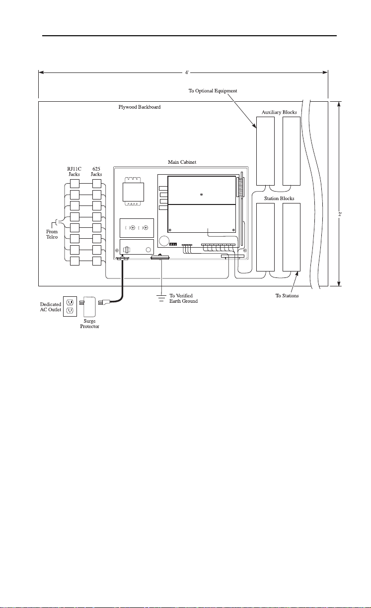
The common equipment is contained in a wall-mounted
cabinet: the Main Cabinet. Choose a central location for
the cabinet that allows enough space for the equipment
— and provides enough room for you to comfortably
work. The Installation Layout (Figure 1-2 on page 1-5)
shows you
requires.
approximately how much space your system
The common equipment cabinet requires a three-prong
dedicated 117 VAC 60 Hz circuit (NEMA 5-15 receptacle) located within 6 feet of the AC receptacle. You
should install the extension block to the right of the
Main Cabinet. Telco should install the RJ11C to the
left of the Main Cabinet.
1-3
Page 6
INSTALLING THE CABINET
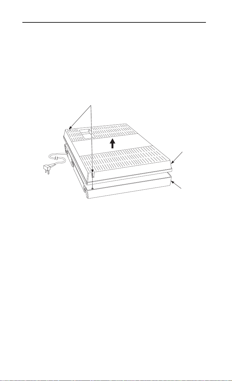
Top Cover
Base Unit
Screws
9300 0 - 8
Removing the Cover (Figure 1-1)
To make wall-mounting easier, remove the cover on the
common equipment cabinet. This allows you to use the
cabinet as a mounting template.
1. Unscrew the two captive screws on the lower half of
the cabinet cover.
2. Lift up the lower half of the cover — then slide the
cover back slightly to remove it.
Figure 1-1 REMOVING THE COVER
Mounting the Cabinet (Figure 1-2)
1. Using suitable fasteners, mount a Main Distribution
Frame (MDF) plywood backboard in a centrally
located spot.
2. Hold the Main Cabinet against the MDF and mark
all four mounting holes.
3. Drill the marked holes using a 1/8” drill bit.
4. Install two mounting screws (provided) in the top two
holes, leaving about 3/8” shank exposed.
5. Hang the Main Cabinet on the top two screws and
fasten in place.
6. Install the bottom two screws and tighten in place.
1-4
Page 7
INSTALLING THE CABINET
824 00 - 13
FO
F1
250V
250V
6.3A
6.3A
Figure 1-2 INSTALLATION LAYOUT
1-5
Page 8
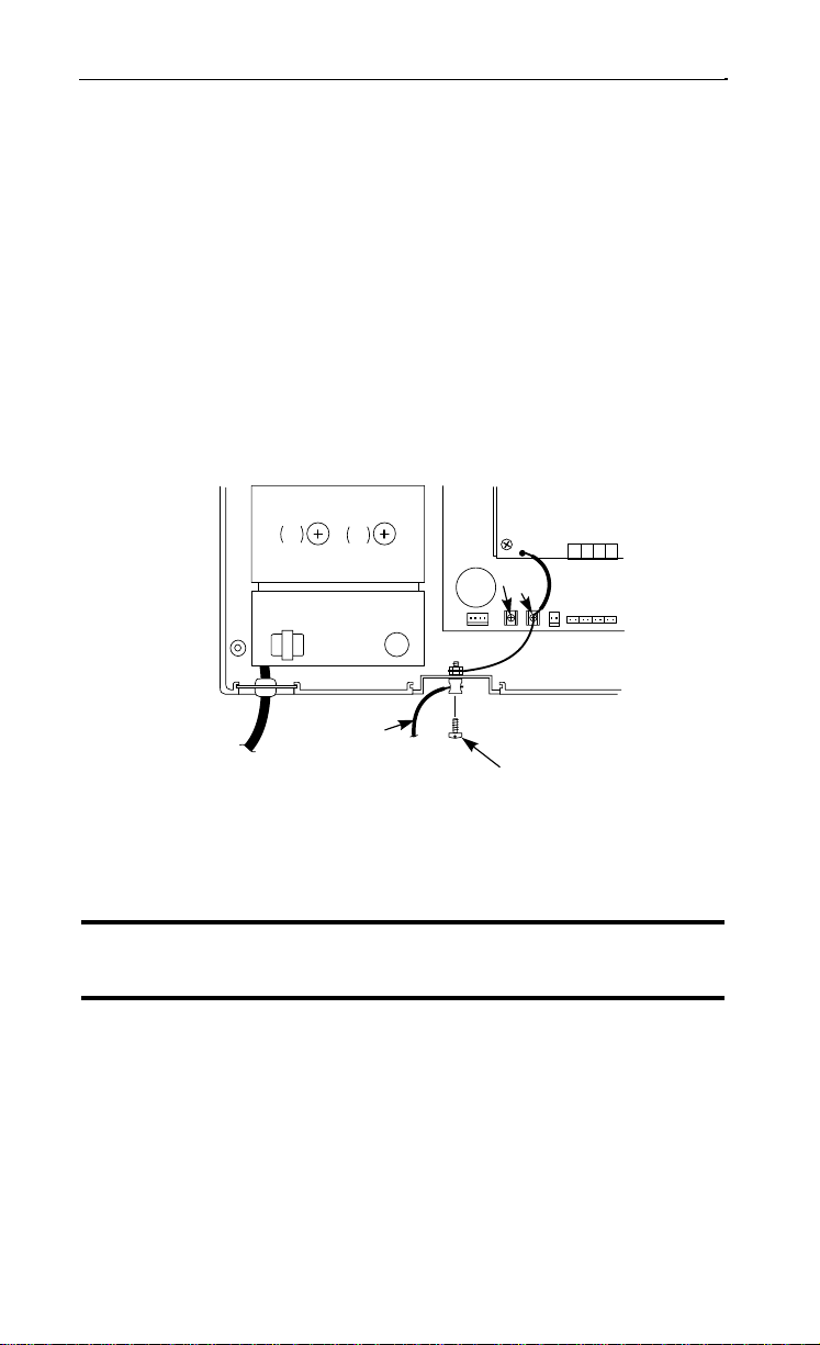
GROUNDING THE CABINET
Connecting the Ground Wires (Figure 1-3)
The cabinet is grounded at the ETH (Earth Ground)
connection.
1. Loosen the lug on the ground connection.
2. Using a piece of 12 AWG stranded copper wire, connect the ETH to the ground connector .
3. Insert 12 AWG stranded copper wire into the
grounding terminal on the outside of the cabinet.
Firmly tighten the connection.
4. Connect the grounding cable to a known earth
ground.
2CO/8STA PCB
82400 - 37
FO
250V
6.3A
F1
250V
6.3A
CPU
ETH
FG
ETH/SG
PFCON
COCN
Grounding
AC Cord
Cable
Screw
Figure 1-3 GROUNDING A CABINET
Now that your cabinet is installed and grounded, go to
Part 2: PCB Installation and Startup.
DO NOT PLUG IN THE CABINET POWER CORD
WITHOUT FIRST INSTALLING THE PCBS.
1-6
Page 9

Section 2
PCB Installation and Startup
In this section . . . Page
PCB Location . . . . . . . . . . . . . . . . . . . . . . . . . . .2-3
Where to Install the PCBs . . . . . . . . . . . . . . . . . . .2-3
Installing PCBs . . . . . . . . . . . . . . . . . . . . . . . . .2-4
Central Processing Unit (CPU) PCB . . . . . . . . . . .2-4
Expansion (2CO/8STA) PCB . . . . . . . . . . . . . . . .2-6
Ring Generator PCB . . . . . . . . . . . . . . . . . . . . . . .2-7
Auxiliary PCB . . . . . . . . . . . . . . . . . . . . . . . . . . . .2-8
Power Failure (4 PF XFER) PCB . . . . . . . . . . . . .2-9
SMDR PCB . . . . . . . . . . . . . . . . . . . . . . . . . . . . .2-10
SMDR RS-232C Cable Assembly . . . . . . . . . . . .2-11
Powering Up the System . . . . . . . . . . . . . . . . .2-12
Power-Up Sequence . . . . . . . . . . . . . . . . . . . . . . .2-12
2. PCB INSTALLATION AND STARTUP
2-1
Page 10

2-2
Page 11
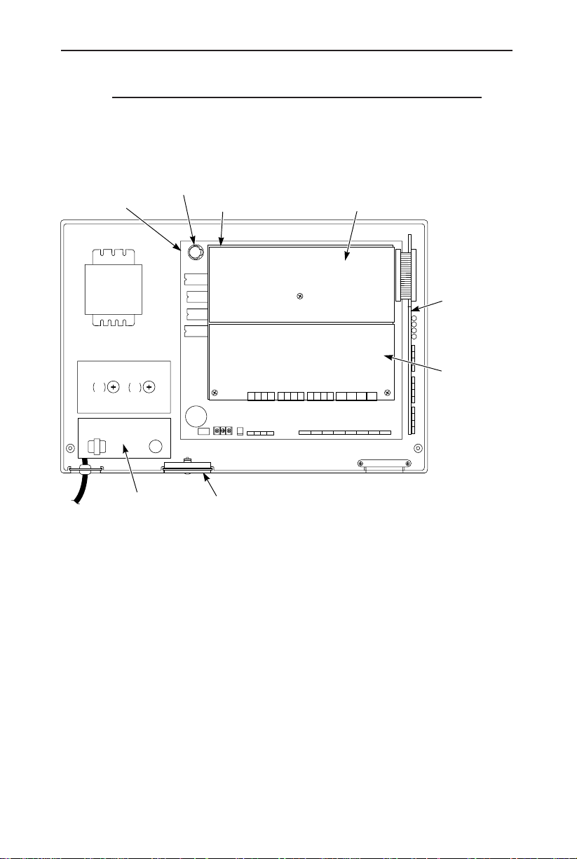
Where to Install the PCBs (Figure 2-1)
Maximum Configuration: 8 Trunks
Lithium Battery
CPU
82400 - 35
2 CO/8 STA PCB SMDR PCB or Caller ID PCB
PCB LOCATION
24 Extensions
Auxillary PCB
FO
F1
250V
250V
6.3A
6.3A
RGUCN
PFCON COCN PFSTN SLTCN
COCN
STCN
Ring Generator PCB RS-232-C Jack and Cable Assembly
Figure 2-1 PCB LOCATION
4 PF XFER PCB
2-3
Page 12
INSTALLING PCBs
82400 - 36
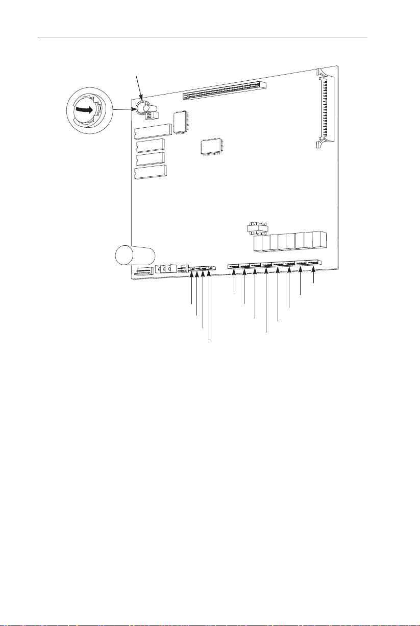
Station 1
Trunk 4
Battery
Trunk 3
Trunk 2
Trunk 1
Station 2
Station 3
Station 4
Station 5
Station 6
Station 7
Station 8
Central Processing Unit (CPU) PCB (Figure 2-2)
Figure 2-2 CPU PCB
The CPU PCB comes already installed in the Main Cabinet.
The CPU provides:
● The system’s central processing, stored program and mem-
ory for the customer’s site-specific data.
● Mode switch for cold (default data) or warm (customer
data) start on power-up.
● Battery for backup of the customer’s site-specific data. Use
only a SONY CR2032 Lithium Battery or equivalent.
Replace the battery when “B” flashes on the display of the
key telephones. The battery’s life is between 3.5 and 7
years - depending on how often the system is powered
down. The more the system’s power is off, the shorter the
battery’s life.
● Connection points for the CO and station DDK connectors.
2-4
Page 13

INSTALLING PCBs
To prepare the CPU PCB:
1. Slide the Switch-1 (top switch) to the INT (left) position.
This ensures that the system will load the default database on initial power-up.
2. Power the system up.
3. After the system has been powered up for a minimum of
10 seconds, insert the battery into the battery clips.
The printing on the battery should be facing up so that
it is visible when installed.
4. Slide the Switch-1 (top) to the RUN position (to the right).
Note: NEVER move the switch unless the intent is to clear
all programmed memory.
Refer to Part 4, Installing Optional Equipment for instructions on installing Background Music and Music on Hold.
2-5
Page 14
INSTALLING PCBs
82400 - 19
CPU
2CO/8STA PCB
ETH
Expansion (2CO/8STA) PCB (Figure 2-3)
Figure 2-3 EXPANSION (2CO/8STA) PCB
The Expansion (2CO/8STA) PCB provides DDK connectors
for two additional CO lines and eight additional telephones.
To install a 2CO/8STA PCB:
1. Place the 2CO/8STA PCB on top of the CPU. Align the
EXPCN female connector on the bottom of the 2CO/8STA
PCB over the EXPCN male connector on the PCB below.
Push down firmly on the expansion PCB to ensure that the
EXPCN connectors are firmly together. Using the additional spacers included with the 2CO/8STA PCB, attach
the PCB to the card below.
2. Connect the green earth ground lead terminal to the ETH
screw on the CPU. An earth ground is always required.
3. Refer to Part 3: Installing Extensions and Trunks for
cabling instructions.
4. If installing a second Expansion PCB, simply place the
card over the first PCB and repeat steps 1-3.
5. To install an Expansion PCB if an SMDR or Power Failure
PCB has been previously installed:
2-6
● Power down the system
● Remove the SMDR and/or Power Failure PCB
● Install the Expansion PCB
● Reinstall the SMDR and/or Power Failure PCBs
● Power up the system.
Page 15
INSTALLING PCBs
82400 - 32
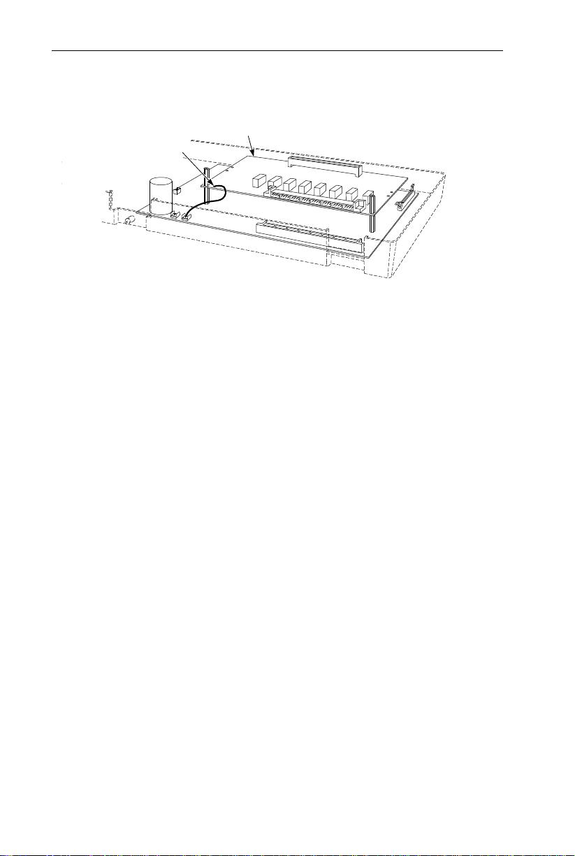
CPU
CPU
RGUCN
Ring Generator
PCB
Ring Generator PCB (Figure 2-4)
Figure 2-4 RING GENERATOR PCB
The Ring Generator PCB provides the ring generator source
when connecting a single line telephone, modem, voice mail,
or answering machine as a system extension. This must be
installed when any single line telephones are used in the system.
To install a Ring Generator PCB:
1. Align the PCB on the left side of the Main Cabinet, below
the power switch. Using the three screws provided, attach
the PCB to the Main Cabinet.
2. Attach the cable from the Ring Generator PCB to the connector labeled RGUCN mounted on the CPU.
2-7
Page 16
INSTALLING PCBs
Auxiliary PCB (Figure 2-5)
Volume Control
VR3VR4VR1VR2
2CO/8STA PCB
Card Holder
CPU
82400 - 20
Figure 2-5 AUXILIARY PCB
The Auxiliary PCB provides:
● 2-pin DDK connectors for two External Paging Zones.
● 2-pin DDK connectors for two Door Boxes.
● 2-pin DDK connectors for two common-use relay contacts.
● 2-pin DDK connectors for Background Music source.
● 2-pin DDK connectors for Music On Hold source.
To install an Auxiliary PCB:
1. Insert the two card holders (included with the PCB) into
the outer holes on the right-hand side of the Main Cabinet.
2. Insert the Auxiliary PCB into the card holders.
3. Connect the ribbon cable (included with the PCB) to the
Auxiliary PCB and then to the DHUCN connector on the
CPU.
4. Refer to Part 4: Installing Optional Equipment for more
on installing Door Boxes, External Paging Equipment and
Alarm Sensors.
2-8
Page 17
INSTALLING PCBs
625
Modular
Jack
Single Line
Telephone
BLK
YEL
RED
GRN
BLU-WHT
WHT-BLU
82400 - 18
Nylon Spacer
Metal Spacer
CPU
2CO/8STA PCB
4 PF XFER PCB
PFCON
To CO Connection
on CPU Card
To Telco
Connection
COCN PFSTN SLTCN
PFUCN
Attached Wire
PFUCN
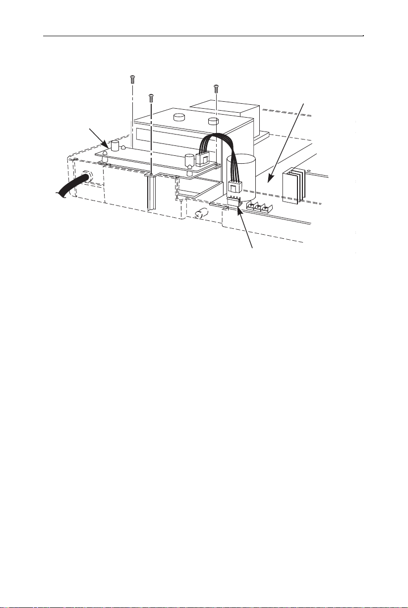
Power Failure (4 PF XFER) PCB (Figure 2-6)
Figure 2-6 POWER FAILURE (4 PF XFER) PCB
The Power Failure (4 PF XFER) PCB provides DDK connectors for four power failure cut through circuits to four single
line telephones.
To install a 4 PF XFER PCB:
1. Place the two nylon spacers included with the 4 PF XFER
PCB in the lower holes in the middle of the CPU (or
2CO/8STA PCB, if installed).
2. Align the 4 PF XFER PCB over the metal and nylon spacers.
3. Using the two metal spacers included with the 4 PF XFER
PCB, attach the PCB to the lower PCB.
4. Refer to Part 4: Installing Optional Equipment for more
on installing Power Failure telephones.
2-9
Page 18
INSTALLING PCBs
82400 - 17
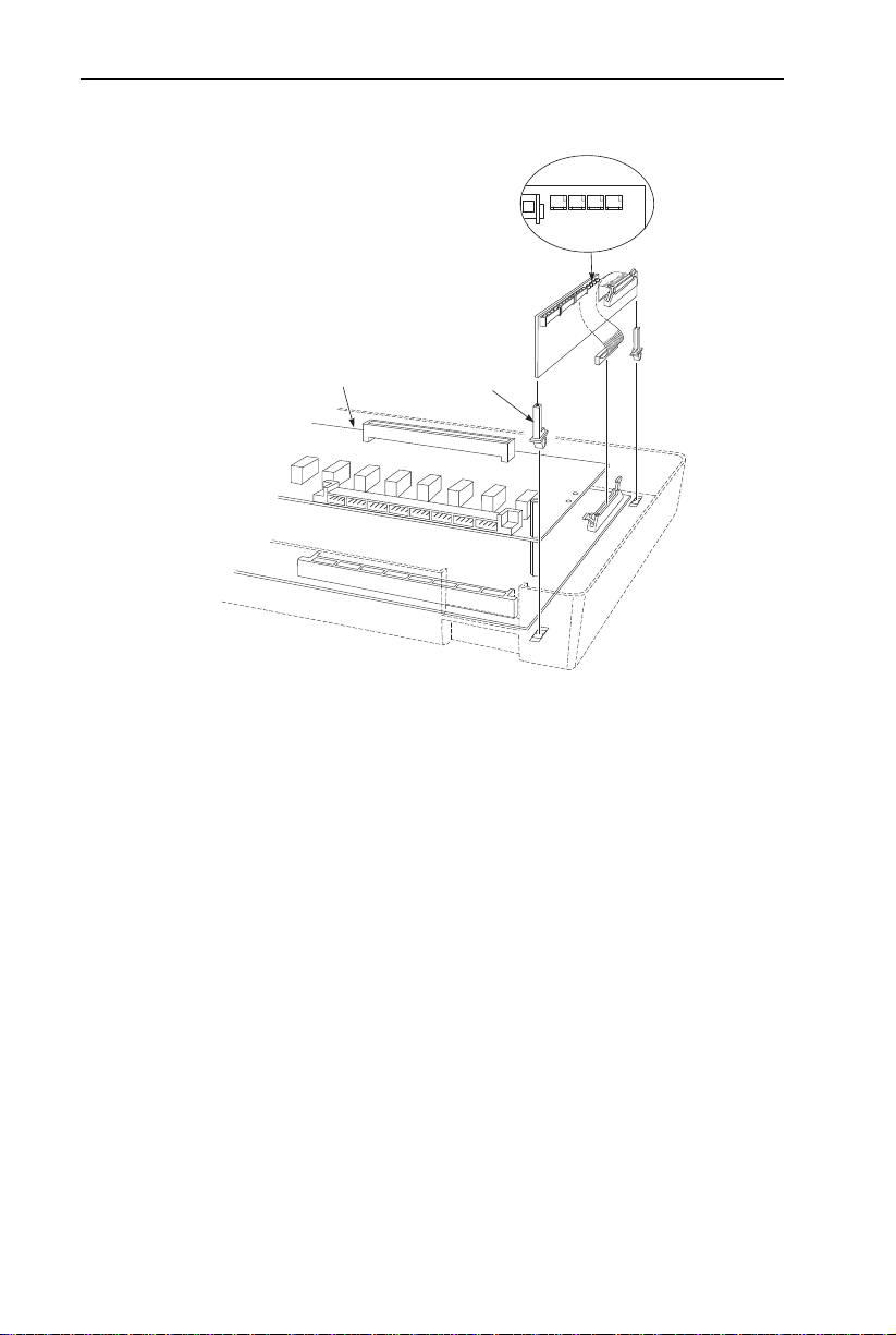
Set SW1 to the proper baud rate position by
placing the jumper over the pins of the
desired baud rate.
SMDR Jack and
Cable Assembly
Nylon Spacer
SMDR
2 CO/8STA
CPU
SMDR PCB (Figure 2-7)
Figure 2-7 SMDR PCB
The SMDR (Station Message Detail Recording) PCB provides a record of the system’s outside calls. Typically, the
record outputs to a customer-provided printer, terminal or
SMDR data collection device. Use SMDR when you need to
monitor the usage at each extension and trunk.
To install a SMDR PCB:
1. Place the two nylon spacers included with the SMDR PCB
in the upper holes in the middle of the CPU (or 2CO/8STA
PCB, if installed).
2. Align the SMDR PCB over the nylon spacers. Press the
PCB into the connector labeled EXPCN on the CPU or
2CO/8STA PCB.
3. Connect the SMDR jack and cable assembly to the Main
Cabinet base. Insert the other end of the cable into the
RSCN connector on the SMDR PCB.
4. Using an RS-232C cable (Figure 2-8), plug the printer into
the SMDR jack assembly. Set the interface conditions of
the printer as follows:
Word length: 7 bits
Parity bit: Even parity
Stop bit length: 2 bits
2-10
Page 19
INSTALLING PCBs
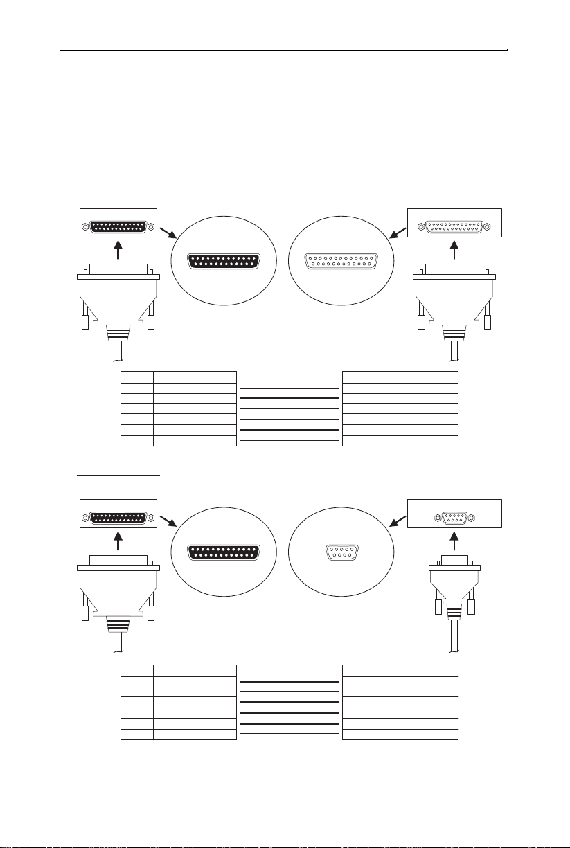
SMDR RS-232C Cable Assembly (Figure 2-8)
To connect the SMDR and printer, an RS-232C cable is required.
If you make your own cable, it must be a straight-through cable
connecting pins 2, 3, 6, 7, 8 and 20. Refer to the Figure 2-8.
Note that the cable length should not exceed 50’in length.
25 pin - 25 pin Cable
SMDR Jack
Output Terminal
Pin No.
2
3
6
7
8
20
25 pin - 9 pin Cable
SMDR Jack
RS-232C (25 pin)
13
25
(female)
Description
Receive Data
Transmit Data
Data Terminal Ready
Signal GND
Request To Send
Data Set Ready
RS-232C (25 pin)
13
25
(female)
RS-232C (25 pin)
1
14
1
14
13
25
(male)
Pin No.
RS-232C (9 pin)
1
6
(male)
1
14
2
Receive Data
3
Transmit Data
6
Data Terminal Ready
7
Signal GND
8
Request To Send
20
Data Set Ready
5
9
82400 - 31
Description
Output Terminal
Pin No.
* The other Pins are not used. These Pin conditions are "Open".
Description
2
Receive Data
3
Transmit Data
6
Data Terminal Ready
7
Signal GND
8
Request To Send
20
Data Set Ready
Pin No.
Figure 2-8 RS-232C CABLE ASSEMBLY
Description
3
Transmit Data
2
Receive Data
6
Data Set Ready
5
Signal GND
1
Data Carrier Detect
4
Data Terminal Ready
2-11
Page 20

POWERING UP THE SYSTEM
Power-Up Sequence
Now that all the PCBs you need are installed, you can powerup the system.
1. Install a surge protector in the AC outlet you intend to use
for system power.
2. Plug the AC power cord for the Main Cabinet into its surge
protector.
System LEDs on Power-Up
PCB LED Status
CPU Processor LED About 5 seconds after power-up,
flashes quickly (red)
2-12
Page 21

Section 3
Installing Extensions and Trunks
In this section . . . Page
Connecting Blocks . . . . . . . . . . . . . . . . . . . . . . . . . . .3-3
Working With DDK Connectors . . . . . . . . . . . . . . . . . . .3-3
Making Additional DDK Connectors . . . . . . . . . . . . . . .3-3
Punching Down a DDK Installation Cable . . . . . . . . . . .3-4
Connecting Extensions . . . . . . . . . . . . . . . . . . . . . . . .3-7
Station Connections . . . . . . . . . . . . . . . . . . . . . . . . . . . .3-7
Connecting Trunks . . . . . . . . . . . . . . . . . . . . . . . . . .3-10
Trunk Connections . . . . . . . . . . . . . . . . . . . . . . . . . . . .3-10
3. INSTALLING EXTENSIONS AND TRUNKS
3-1
Page 22

3-2
Page 23

CONNECTING BLOCKS
Working With DDK Connectors
The system uses DDK-type connectors for extensions, trunks and
optional equipment. Using the optional DDK Installation Cables (4pin station cable=P/N 82490, 2-pin power failure cable=82491, and
2-pin C.O. line cable=82492) makes it easy to connect the PCBs to
standard 66M1-50 connecting blocks. The cables available for the
system are for CO lines (one-pair), keysets (2-pair), and Power
Failure Jumpers/auxiliary options (one-pair). If desired, separate
DDK connectors without cable can be purchased. In general, each
cabinet needs:
● Two 66M1-50 block and DDK Installation Cable for extensions.
● One 66M1-50 block and DDK Installation Cable for optional
equipment
● One to eight (depending on your requirements) RJ11C modular
jacks and one DDK Installation Cable for trunks.
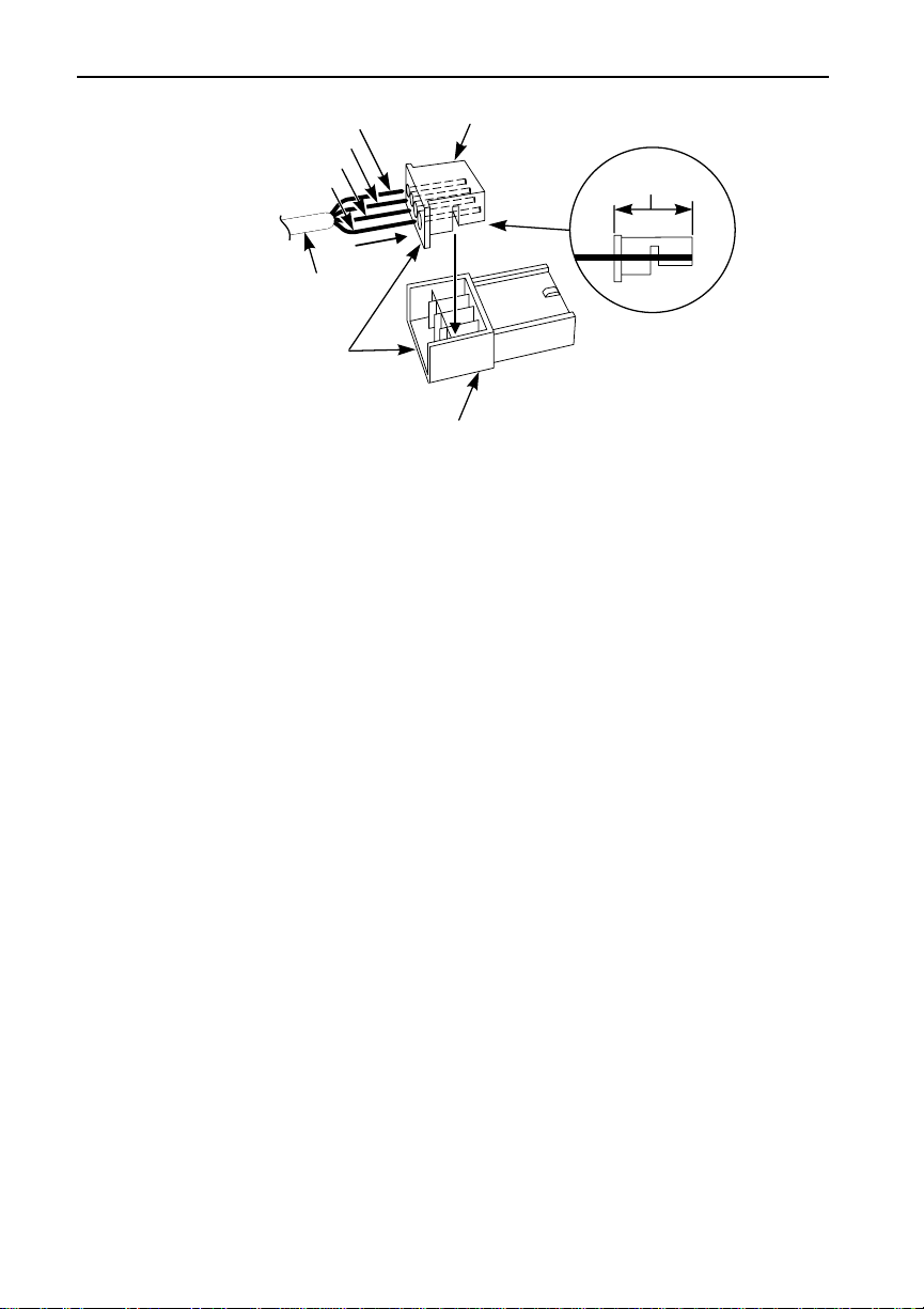
Making Additional DDK Connectors
(Figure 3-1)
To make DDK connectors, using 22 or 24 gauge solid 2-pair twisted
wire for keysets or 22 or 24 gauge solid 1-pair twisted wire for CO
lines, single line telephones, Power Failure Jumpers, or auxiliary
functions, do the following:
1. Do not strip the wires. Insert the wires into the top piece (clear
plastic) of the connector. Following the standard color code:
#1=White/Blue, #2=Blue/White,
#3=White/Orange, #4=Orange/White
(Ignore #3 and #4 if only using 1-pair twisted wire)
Refer to Figure 3-4 for additional help with the color code. Make
sure that the wire ends do not protrude beyond the back of the
connector.
2. Place the top half of the connector over the lower half and press
down or use pliers to snap together. Verify that the connector
will not come apart and that all the wires are secure. Once
together, these connectors will not separate without breaking.
3-3
Page 24
CONNECTING BLOCKS
Upper Half
82400 - 30
Approx. 5/16"
Lower Half
DDK Connector
Two pair twisted
telephone wire
WHT/BLU
BLU/WHT
WHT/ORN
ORN/WHT
1 (T)
2 (R)
3 (H)
4 (L)
Figure 3-1 MAKING DDK CONNECTORS
Punching Down a DDK Installation Cable
The DDK Installation Cables have 4-pin DDK connectors installed
on one end and are unterminated on the other.
1. For each 66M1-50 block, punch down the DDK Installation
Cable in standard color-code order.
Refer to Figure 3-3 if you need help with the color code.
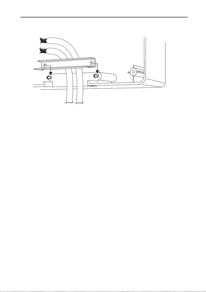
2. After you have punched down your cables, route them through
the bottom of the cabinet and secure them with the strain relief
bar (Figure 3-2).
3-4
Page 25
CONNECTING BLOCKS
Figure 3-2 SECURING THE CABLES
82400 - 29
3-5
Page 26

CONNECTING BLOCKS
- Only CPU
No Connection
- With one
expansion PCB
- With two
expansion PCB’s
T
R
H
L
= Tip
= Ring
= High
= Low
3-6
Figure 3-3 CONNECTING BLOCK
Page 27

STCN
STCN
CPU
2CO/8STA PCB
TEL9/17
TEL1
10/18
TEL2
11/19
TEL3
12/20
TEL4
13/21
TEL5
14/22
TEL6
15/23
TEL7
16/24
TEL8
82400 - 25
CONNECTING EXTENSIONS
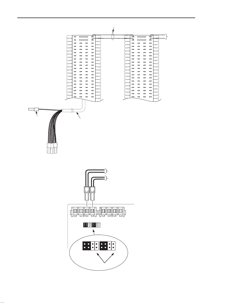
Station Connections (Figure 3-4)
The CPU has 4-pin DDK connectors for eight stations. Each
Expansion (2CO/8STA) PCB provides for an additional eight stations. Two Expansion PCB’s are allowed per system providing a
total of twenty-four stations per system.
Refer to Part 4: Installing Optional Equipment for instructions on connecting a power failure telephone.
Figure 3-4 STATION CONNECTIONS
1. Following the conventional color code, insert the DDK connectors into the PCB. For example, the first eight stations in the system would have these connections:
Ext./Port DDK Connector Pair
10 WHT-BLU / BLU-WHT / WHT-ORN / ORN-WHT
11 WHT-GRN / GRN-WHT / WHT-BRN / BRN WHT
12 WHT-SLT / SLT-WHT / RED-BLU / BLU-RED
13 RED-ORN / ORN-RED / RED-GRN / GRN-RED
14 RED-BRN / BRN-RED / RED-SLT / SLT-RED
15 BLK-BLU / BLU-BLK / BLK-ORN / ORN-BLK
16 BLK-GRN / GRN-BLK / BLK-BRN / BRN-BLK
17 BLK-SLT / SLT-BLK / YEL-BLU / BLU-YEL
Note that single line telephones only use one-pair wire
(T/R). When installing a single line set, the second pair is
not used (H/L).
2. Install a modular jack for each extension within six feet of the
telephone’s location. See Figure 3-5.
3-7
Page 28

CONNECTING EXTENSIONS
3. For each keyset, run two-pair 24 AWG station cable from the
cross-connect block to the modular jack. For each single line
phone, run one-pair 24 AWG station cable from the cross-connect block to the modular jack.
4. Terminate the station cable to the module jack lugs:
WHT-BLU to GREEN lug
BLU-WHT to RED lug
WHT-ORN to BLACK lug *
ORN-WHT to YELLOW lug *
* Lug not used when installing a single line phone.
5. Back at the MDF, run two pairs of cross-connect wires (or one
pair of cross-connect wires for single line phones) between the
pins on the B block and cross-connect block to complete the
connection.
6. Install bridging clips as required.
7. After completing step 6, you should be able to place and answer
calls at the extension.
Two Pair
Cross Connect
3-8
ORN-WHT WHT-ORN
"B"
Block
YEL
BLU-WHT
Cross
Connect
Block
DDK Installation Cable
RED
625
Modular
Jack
BLK
WHT-BLU
GRN
Figure 3-5 CONNECTING KEYSET TELEPHONES
82400 - 5
Page 29

CONNECTING EXTENSIONS
625
Modular
Jack
Single Line
Telephone
BLKYEL
RED GRN
BLU-WHT
WHT-BLU
One-Pair Cross-Connect
DDK
Connector
25-Pair DDK
Installation Cable
"B" Block
Cross
Connect
Block
82400 - 48
Figure 3-6 CONNECTING SINGLE LINE TELEPHONES
3-9
Page 30

CONNECTING TRUNKS
82400 - 26
CO2 CO3 CO4
COCN
CO1
CPU
CO/PBX Line 4
CO/PBX Line 2
CO/PBX Line 3
CO/PBX Line 1
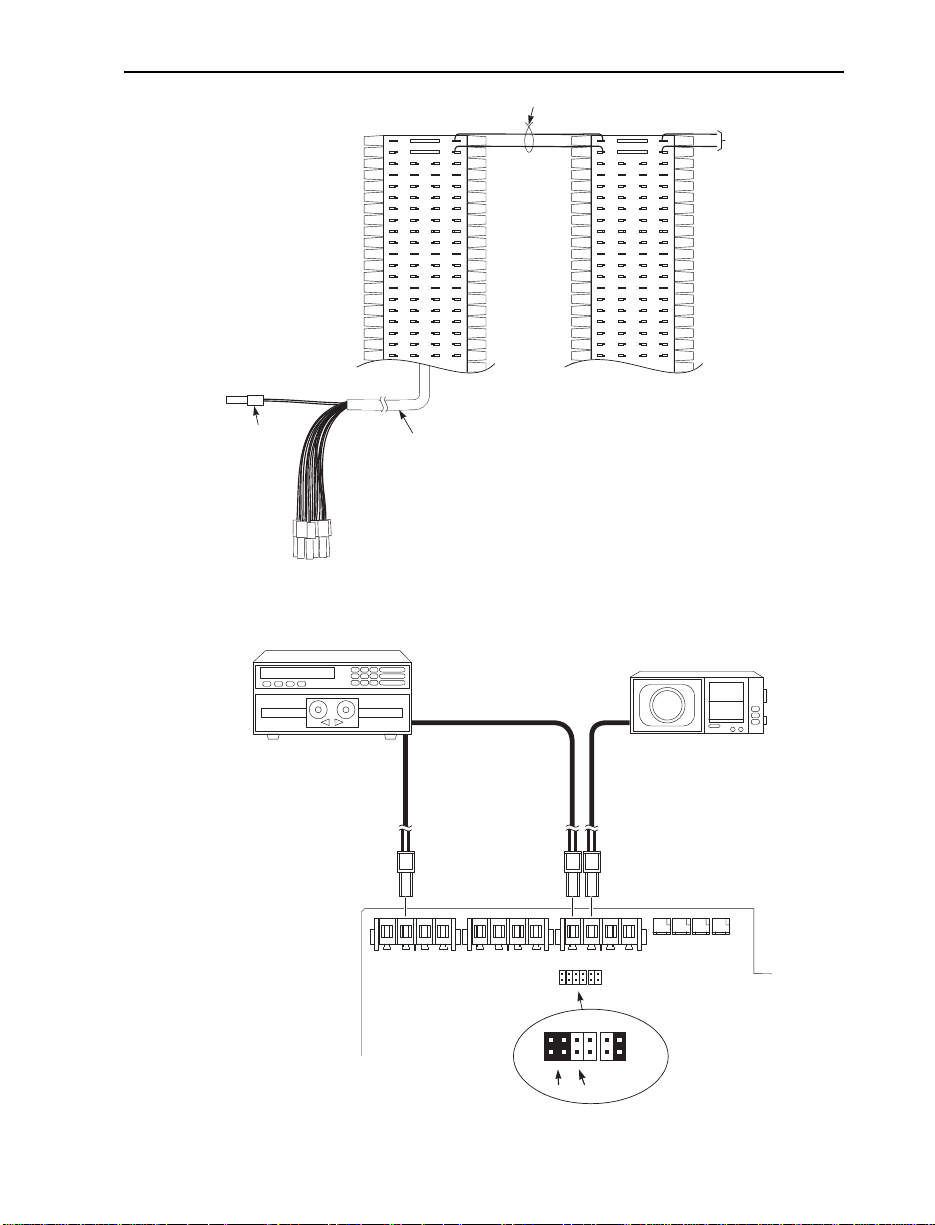
Trunk Connections (Figure 3-7)
The CPU has 2-pin DDK connectors for four loop start CO trunks.
Each Expansion (2CO/8STA) PCB provides an additional two CO
trunk connections. Two Expansion PCB’s are allowed per system
providing a total of eight trunks per system.
Refer to Part 4: Installing Optional Equipment for instructions on connecting a power failure telephone.
2CO/8STA PCB
COCN
CO6/8
CO5/7
82400 - 24
CO/PBX Line 6 or 8
CO/PBX Line 5 or 7
Figure 3-7 TRUNK CONNECTIONS
1. Following the conventional color code, insert the DDK connectors into the PCB. For example, the CPU would have these connections:
Trunk DDK Connector Pair
1 WHT-BLU / BLU-WHT
2 WHT-ORN / ORN-WHT
3 WHT-GRN / GRN-WHT
4 WHT-BRN / BRN WHT
2. For each trunk, run one pair of wires from the DDK connection
to a 625 modular jack, which then connects to the telco’s RJ11C
jacks using a standard line cord (Figure 3-8 on the following
page).
3. After completing step 2, you should be able to place and answer
calls over the connected trunk.
3-10
Page 31

CONNECTING TRUNKS
625
Modular
Jack
Line
Cord
RED
GRN
BLU-WHT
WHT-BLU
DDK
Connector
To CO connector
on CPU or
2CO/8STA PCB
25-Pair DDK
Installation Cable
To Central Office
Telco
RJ11C
82400 - 12
Figure 3-8 CONNECTING TRUNKS
3-11
Page 32

3-12
Page 33

Section 4
Installing Optional Equipment
In this section . . . Page
Alarm Sensors . . . . . . . . . . . . . . . . . . . . . . . . . . . . . . . .4-3
Using External Alarm Sensors . . . . . . . . . . . . . . . . . . . . . .4-3
Installing an External Alarm Sensor Circuit . . . . . . . . . . . .4-3
Caller ID . . . . . . . . . . . . . . . . . . . . . . . . . . . . . . . . . . . . .4-5
Using Caller ID . . . . . . . . . . . . . . . . . . . . . . . . . . . . . . . . . .4-5
Installing Caller ID . . . . . . . . . . . . . . . . . . . . . . . . . . . . . . .4-5
DSS Console . . . . . . . . . . . . . . . . . . . . . . . . . . . . . . . . . .4-8
Using a Direct Station Selection Console . . . . . . . . . . . . . .4-8
Installing a DSS Console . . . . . . . . . . . . . . . . . . . . . . . . . .4-8
External Paging and Page Relays . . . . . . . . . . . . . . . . .4-9
Using External Paging . . . . . . . . . . . . . . . . . . . . . . . . . . . .4-9
Installing External Paging and Page Relays . . . . . . . . . . . .4-9
Door Box . . . . . . . . . . . . . . . . . . . . . . . . . . . . . . . . . . . .4-12
Using the Door Box . . . . . . . . . . . . . . . . . . . . . . . . . . . . .4-12
Installing a Door Box . . . . . . . . . . . . . . . . . . . . . . . . . . . .4-12
Installing Door Strike Control Relays . . . . . . . . . . . . . . . .4-14
Music Sources . . . . . . . . . . . . . . . . . . . . . . . . . . . . . . . .4-16
Music on Hold and Background Music . . . . . . . . . . . . . .4-16
Installing a Music Source on an Auxiliary PCB . . . . . . . .4-16
Power Failure Telephones . . . . . . . . . . . . . . . . . . . . . .4-18
Power Failure Cut-Through . . . . . . . . . . . . . . . . . . . . . . .4-18
Installing a Power Failure Telephone . . . . . . . . . . . . . . . .4-18
Voice Mail . . . . . . . . . . . . . . . . . . . . . . . . . . . . . . . . . . .4-20
Using Voice Mail . . . . . . . . . . . . . . . . . . . . . . . . . . . . . . . .4-20
Installation . . . . . . . . . . . . . . . . . . . . . . . . . . . . . . . . . . . . .4-21
Wall-Mount Kit . . . . . . . . . . . . . . . . . . . . . . . . . . . . . .4-23
Using the Wall-Mount Kit . . . . . . . . . . . . . . . . . . . . . . . . .4-23
Installing the Wall-Mount Handset Hanger . . . . . . . . . . .4-23
Wall-Mounting a Key Telephone . . . . . . . . . . . . . . . . . . .4-24
4. INSTALLING OPTIONAL EQUIPMENT
4-1
Page 34

4-2
Page 35

ALARM SENSORS
Using External Alarm Sensors
The Auxiliary PCB provides two alarm circuits which detect a make
(open) or break (closed) contact from an alarm. Programming determines if the alarm inputs require an open or closed circuit.
An alarm detection causes the system to send a signal to stations programmed to receive the alarms. The alarm signal can also be sent to
external paging speakers.
Note: The Auxiliary PCB alarm feature can use a 10-30 VDC power
supply installed in series with the alarm circuit.
Installing an External Alarm Circuit
CAUTION
Be sure the requirements of the alarm system sensors do not exceed
the system specifications.
With Internal Power: loop resistance of less than 100 Ohms
With External DC Power: 5 to 24 VDC with 0.65 mA to 4.5 mA
Note: External powered alarm sensors are polarity sensitive
(see Figure 4-2). Additionally, the external powershould
provide current limiting.
1. Locate an available 2-pin DDK connector in an auxiliary (C)
block.
2. For the DDK connector chosen, cross-connect the associated wire
pair from the C block to the cross-connect block.
3. Install bridging clips as required.
4. Connect the two leads from the first external alarm to the associated terminals on the cross-connect block.
5. Plug the DDK connector into the ALM1 connector on the
Auxiliary PCB.
6. Repeat steps 1-4 for the second external alarm, if required.
(Figure 4-1)
7. Plug the DDK connector into the ALM2 connector on the
Auxiliary PCB.
Note: When using internal power to connect the dry contact of an
alarm-detecting device to the system, set the SW3 switch (Alarm
1) and SW4 switch (Alarm 2) on the Auxiliary PCB to INPOW.
4-3
Page 36
ALARM SENSORS
One-Pair Cross-Connect
DDK
Connector
To alarm input
on Auxiliary PCB
25-Pair DDK
Installation Cable
"C" Block
Cross
Connect
Block
Input from
alarm
system
82400 - 11
4-4
Figure 4-1 CONNECTING AN ALARM
SW3
power
CTR2RL2
EXPOW
Alarm Input 2
Alarm Input 1
CN2CN1
SPK2RL1
CTR1ALM2
SW3
SPK1ALM1
Auxiliary PCB
11
22
SW4
EXPOW EXPOW
INPOW INPOW
82400 - 40
SW4
EXPOW
INPOW INPOW
(ALM2) (ALM1)
Using internal
Figure 4-2 CONNECTING TO THE AUXILIARY PCB
Page 37

CALLER ID
1
1
2
2
INT RST
RUN
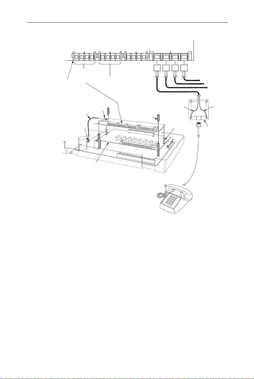
Using Caller ID
Caller ID allows a display keyset to show an incoming caller’s telephone number and/or name with the time and date on the phones display. The caller’s information can be checked before answering an
incoming call. The information received by the system depends upon
the capabilities of your local telco.
The system requires the following:
● System Software 2.1B or higher
● Caller ID/SMDR PCB (P/N 82421)
This PCB is used in place of the SMDR PCB (P/N 82420) and
provides both Caller ID and SMDR capability.
● Caller ID Adaptor (P/N 82425)
The Caller ID Adaptor provides 8 detection circuits for Caller
ID data.
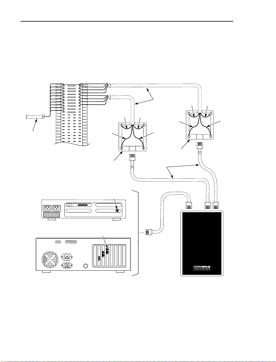
Installation (Figure 4-3)
1. Locate a clean, dry spot that is out of direct sunlight and near the
Portrait KSU. The Caller ID Adaptor must be installed within 2’ of
the lower right side of the KSU (determined by the length of the
interconnecting cable). The area should be well ventilated and the
temperature should remain at a normal level.
2. Remove the cover from the Caller ID Adaptor.
3. Tack-fasten two of the four wood screws (provided) on the wall at
about 8 11/16” apart. For easier installation, you can use the base
as a mounting template.
4. Place the Caller ID Adaptor over the tacked screws. Fully tighten
the screws and install the remaining two wood screws.
5. Remove the cover from the KSU by unscrewing the two captive
screws on the lower half of the cabinet cover. Lift up the lower
half of the cover -- then slide it back slightly to remove it.
6. Before proceeding further, make sure switches
1 & 2 of the CPU Mode Switch are set to the
RUN position and the battery is installed in
the system. This is necessary in order to
retain the current system programming.
7. Unplug the AC power cord for the KSU from its surge protector.
4-5
Page 38

CALLER ID
8. Set the jumpers on the Caller ID/SMDR PCB. Set jumper-SW1 to
match the baud rate of the SMDR Unit. Set jumper-SW2 to the
“RUN” position, this setting allows the system to use the customer’s current programming.
9. Place the two nylon spacers included with the Caller ID/SMDR
PCB in the upper holes in the middle of the CPU (or 2CO/8STA
PCB, if installed).
10. Align the Caller ID/SMDR PCB over the nylon spacers. Press the
PCB into the connector labeled EXPCN on the CPU or 2CO/8STA
PCB. The PCB should then be snapped on to the spacers.
11. Connect the Caller ID cable to the CBCN connector and G termi-
nal on the Caller ID/SMDR PCB. Connect the opposite end to the
SMDCN connector and G terminal on the Caller ID Adaptor.
12. Mount the SMDR jack (RS-232 connector) to the base of the
KSU. Connect the opposite end of the cable to the RSCN connector on the Caller ID/SMDR PCB.
13. Connect the FG ground on the KSU to the ETH ground connector
on the Caller ID Adaptor using the green wire with spade lug ends
provided.
14. With DDK connectors attached to both ends, connect a one-pair
jumper from the TRCN connector on the Caller ID Adaptor to the
corresponding COCN connector on either the CPU or Expansion
(2CO/8STA) PCB. Repeat this step for additional CO lines.
15. For each CO trunk, run one pair of wires with DDK connectors on
one end from the COCN connector on the Caller ID Adaptor to a
625 modular jack. The jack is then connected to telco’s RJ11C
jack using a standard line cord.
16. Replace the front cover on the KSU, and the front cover on the
Caller ID Adaptor.
17. Plug the AC power cord for the KSU into its surge protector.
18. Refer to the Portrait Pocket Guide (P/N 824000PKT**) for
required programming.
4-6
Page 39

82400 - 58
FG
SG
COCN
CO1
CO4
CPU
2 CO/8 STA
ETH
COCN CO1CO8TRCN COTR1COTR8SMDCN
G
COTR8
625
Jack
Caller ID Adaptor
Portrait KSU
SMDR Jack and
Cable Assembly
Set SW1 to the proper
baud rate position placing
the jumper over the pins
of the desired baud rate.
To
Telco
Nylon
Spacer
CBCN
G
SW2
TEST RUN
Caller ID/SMDR PCB
CALLER ID
Figure 4-3 CONNECTING CALLER ID
4-7
Page 40

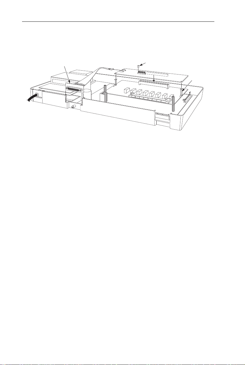
DSS CONSOLE
Using a Direct Station Selection Console
The DSS Console gives a
extensions. The system supports a maximum of 3 DSS Consoles.
Installing a DSS Console (Figure 4-4)
1. Unplug the telephone and remove the handset cord from the telephone’s base.
2. Remove the four screws on the bottom of the telephone.
3. Using a knife remove the plastic piece on the base to allow space
for the ribbon cable, using care not to leave any rough edges which
could cause damage to the cable.
4. Insert the ribbon cable from the DSS into the CN3 connector on
the PCB in the telephone.
5. Replace the bottom plate of the telephone and attach with the four
screws.
display keyset user one-button access to
4-8
82400 - 14
Use a knife to
scrape away.
Figure 4-4 CONNECTING THE DSS CONSOLE
Page 41

EXTERNAL PAGING AND PAGE RELAYS
Using External Paging
Each Auxiliary PCB has two External Paging audio outputs and two
associated control relays. The External Page zones are two way which
provide for the ability to do talk back paging (no additional programming required). The audio outputs are connected to audio inputs on
customer-provided paging systems. In some paging systems, you can
use the control relays to automatically turn the amplifiers on and off.
The control relays are normally open and close whenever a user calls
the External Paging zone.
Installing External Paging and Page Relays (Figure 4-5)
CAUTION
Be sure the audio input requirements of the paging equipment are
compatible with the audio output specifications of the system.
Output Impedance: 600 Ohms
Output Level: Nominal 250 mV (-10 dBm)
Maximum Output: 400 mV RMS
Minimum Initial Contact Resistance: 50 mOhms
Relay Contact: 250 mA @ 24 VDC
1. Locate an available 2-pin DDK connector in an auxiliary (C) block.
2. For the DDK connector chosen, cross-connect the associated wire
pair from the C block to the cross-connect block.
3. Install bridging clips as required.
4. Connect two leads to the paging system audio inputs.
5. For External Zone 1, loop the cable once through a ferrite bead
(supplied with the Auxiliary PCB) then plug the DDK connectors
into the Auxiliary PCB. One connector is plugged into the connector on the PCB labeled SPK1, the other goes to CTR1.
6. For External Zone 2, loop the cable once through the same ferrite
bead used for External Zone 1, then plug the DDK connectors into
the Auxiliary PCB. One connector is plugged into the connector on
the PCB labeled SPK2, the other goes to CTR2.
7. Adjust the volume level of each External Zone. VR1 controls zone
1 (accessed by dialing 86), VR2 controls zone 2 (accessed by dialing 87).
4-9
Page 42

EXTERNAL PAGING AND PAGE RELAYS
One-Pair Cross-Connect
DDK
Connector
To External Page
audio output on
Auxiliary PCB
25-Pair DDK
Installation Cable
"C" Block
Cross
Connect
Block
Output to
paging
system
control
inputs
82400 - 10
One-Pair Cross-Connect
DDK
Connector
To Control Relay
on Auxiliary PCB
25-Pair DDK
Installation Cable
"C" Block
Cross
Connect
Block
Output to
paging
system
control
inputs
82400 - 9
Figure 4-5 CONNECTING EXTERNAL PAGING/RELAYS
4-10
Figure 4-6 CONNECTING EXTERNAL PAGING
Page 43

EXTERNAL PAGING AND PAGE RELAYS
Ferrite bead
To Paging
or Door Box
connection
Loop each cable once
through Ferrite bead
DDK connectors
to Auxiliary PCB
82400 -53
Figure 4-7 ATTACHING THE FERRITE BEAD
Paging Speaker #2 Paging Speaker #1
Amplifier Amplifier
SPK1/SPK2: External paging audio signal output.
CTR1/CTR2: Normally open relay contacts. If a zone
EXMOHCTR2RL2
82400 - 21
Figure 4-8 CONNECTING CONTROL RELAYS TO THE AUXILIARY PCB
SPK1ALM1
Auxiliary PCB
is activated, the contacts close.
(SPK2)
BGMSPK2RL1
DH2CTR1ALM2
DH1
VR3VR4VR1VR2CN3CN2CN1
(SPK1)
(DH2)
(DH1)
4-11
Page 44

DOOR BOX
Using the Door Box
Each Auxiliary PCB supports two Door Boxes. In addition, you can
connect each circuit’ s control relay to an electric door strike. This
allows an extension user to remotely activate the door strike while talking to a visitor at the Door Box. The control relays are normally open.
Installing a Door Box (Figure 4-9)
1. Locate an available 2-pin DDK connector in an auxiliary (C) block.
2. For the DDK connector chosen, cross-connect the associated wire
pair from the C block to the cross-connect block.
3. Connect leads from lugs 1 and 2 on the Door Box to the cross-connect block. Be sure to maintain the proper polarity.
4. Loop the cable once through a ferrite bead (supplied with the
Auxiliary PCB), then plug the DDK connector into the Door Box
(1 or 2) connector on the Auxiliary PCB. The first Door Box is
labeled DH1 on the PCB. The second Door Box is labeled DH2.
If both Door Boxes are to be used, loop both cables through
the same ferrite bead.
5. Install bridging clips as required.
6. Use VR3 or VR4 to adjust the volume of the Door Box. VR3 corresponds to Door Box 1, VR4 corresponds to Door Box 2.
4-12
5
L
T
6
C
T
1
2 3 4
L F
*
RED-BRN
BRN-RED
*
RED-SLT
SLT-RED
Misc Block
* typical installation
To Door Chime Box 1
21
22
23
24
Holes for
mounting screws
To Door
Chime Box 2
Rear view
92 0 - 1 59 A
Figure 4-9 CONNECTING A DOOR BOX
Page 45

Figure 4-10 ATTACHING THE FERRITE BEAD
One-Pair Cross-Connect
DDK
Connector
To DHI or DH2 connector
on Auxiliary PCB
25-Pair DDK
Installation Cable
"C" Block
Cross
Connect
Block
Output to
door box
82400 - 42
Ferrite bead
To Paging
or Door Box
connection
Loop each cable once
through Ferrite bead
DDK connectors
to Auxiliary PCB
82400 -53
DOOR BOX
Figure 4-11 CONNECTING A DOOR BOX
4-13
Page 46

DOOR BOX
Installing Door Strike Control Relays (Figure 4-12)
CAUTION
Be sure the requirements of the door strike are compatible with the
control relay output specifications of the system.
Contact Configuration: Normally open
Maximum Load: 250 mA@ 24 VDC
Maximum Initial Contact Resistance: 50 mOhms
1. Locate an available 2-pin DDK connector in an auxiliary (C)
block.
2. For the DDK connector chosen, cross-connect the associated wire
pair from the C block to the cross-connect block.
3. Connect two leads from the door strike to the associated terminals
on the cross-connect block.
If the door strike is a high current device, you may have to
install an auxiliary relay that powers the door strike relay.
4. Plug the DDK connector into the Auxiliary PCB connector labeled
RL1 or RL2. RL1 controls the door strike relay for Door Box 1,
RL2 controls Door Box 2.
5. Install bridging clips as required.
4-14
Page 47

82400 - 43
EXMOHCTR2RL2 DH1SPK1ALM1 BGM
SW2
INT
(MOH)
(BGM)
EXTOFF ON
SW1
SPK2RL1 DH2CTR1ALM2
(SPK2)(SPK1) (DH2) (DH1)
Auxiliary PCB
Door Box
To Door Strike
Terminals
VR3VR4VR1VR2CN3CN2CN1
One-Pair Cross-Connect
DOOR BOX
Output to
door strike
To Control Relay
on Auxiliary PCB
DDK
Connector
"C" Block
25-Pair DDK
Installation Cable
Connect
82400 - 8
Cross
Block
Figure 4-12 CONNECTING TO THE DOOR STRIKE
Figure 4-13 CONNECTING DOOR BOX/DOOR STRIKE RELAYS TO THE
AUXILIARY PCB
4-15
Page 48

MUSIC SOURCES
Music on Hold and Background Music
Music on Hold (MOH) provides music to callers on Hold and calls
parked in orbit. The system’s default setting provides an internal
(synthesized) MOH music source, or a customer-provided music
source connected to the Auxiliary PCB can be used instead (see
below).
Background Music sends music from a customer-provided music
source (via a connector on the Auxiliary PCB) to keyset speakers.
Installing a Music Source on the Auxiliary PCB (Figure 4-14)
CAUTION
Be sure the music source is compatible with the MOH and BGM
input specifications on the CPU PCB.
Input Impedance: 600 Ohm
Input Level: Nominal 250 mV (-10 dBm)
Maximum Input: 1V RMS
1. Locate an available 2-pin DDK connector in an auxiliary (C) block.
2. For the DDK connector chosen, cross-connect the associated wire
pair from the C block to the cross-connect block.
3. Connect two leads from the customer-provided music source to the
associated terminals on the cross-connect block.
4. For Music on Hold . . .
a. Plug the DDK connector into the EXMOH input on the
Auxiliary PCB.
b. Set the SW2 strap to the EXT position.
If MOH not is not required (either from an external source or
from the system’s synthesized MOH), set the SW2 strap in the
EXT position and do not plug any music source into the
EXMOH input on the Page/Door Box card.
For Background Music . . .
a. Plug the DDK connector into the BGM input on the Auxiliary
PCB.
b. Set the SW1 strap to the ON position. If BGM is not required,
set the SW2 strap to the OFF position.
5. Install bridging clips as required.
6. Adjust the volume for the MOH and BGM on the external sources.
4-16
Page 49
MUSIC SOURCES
One-Pair Cross-Connect
DDK
Connector
To MOH or BGM
on Auxiliary PCB
25-Pair DDK
Installation Cable
"C" Block
Cross
Connect
Block
To
music
source
82400 - 7
Figure 4-14 CONNECTING MUSIC SOURCES
External MOH Source
(MOH)
INT
EXMOHCTR2RL2 DH1SPK1ALM1 BGM
(MOH)
INT
Off
(SPK2)(SPK1) (DH2) (DH1)
SW2
SW1
(BGM)
EXT
OFF
SW2
SW1
OFFONON
(BGM)
EXT
On
The relay contacts RL1 and
RL2 can be used as
MOH/BGM device control.
The remote control terminal
on the device must be
connected to these contacts.
(see Program 56)
SPK2RL1 DH2CTR1ALM2
Auxiliary PCB
82400 - 22
Figure 4-15 CONNECTING TO THE AUXILIARY PCB
BGM Source
VR3VR4VR1VR2CN3CN2CN1
4-17
Page 50

POWER FAILURE TELEPHONES
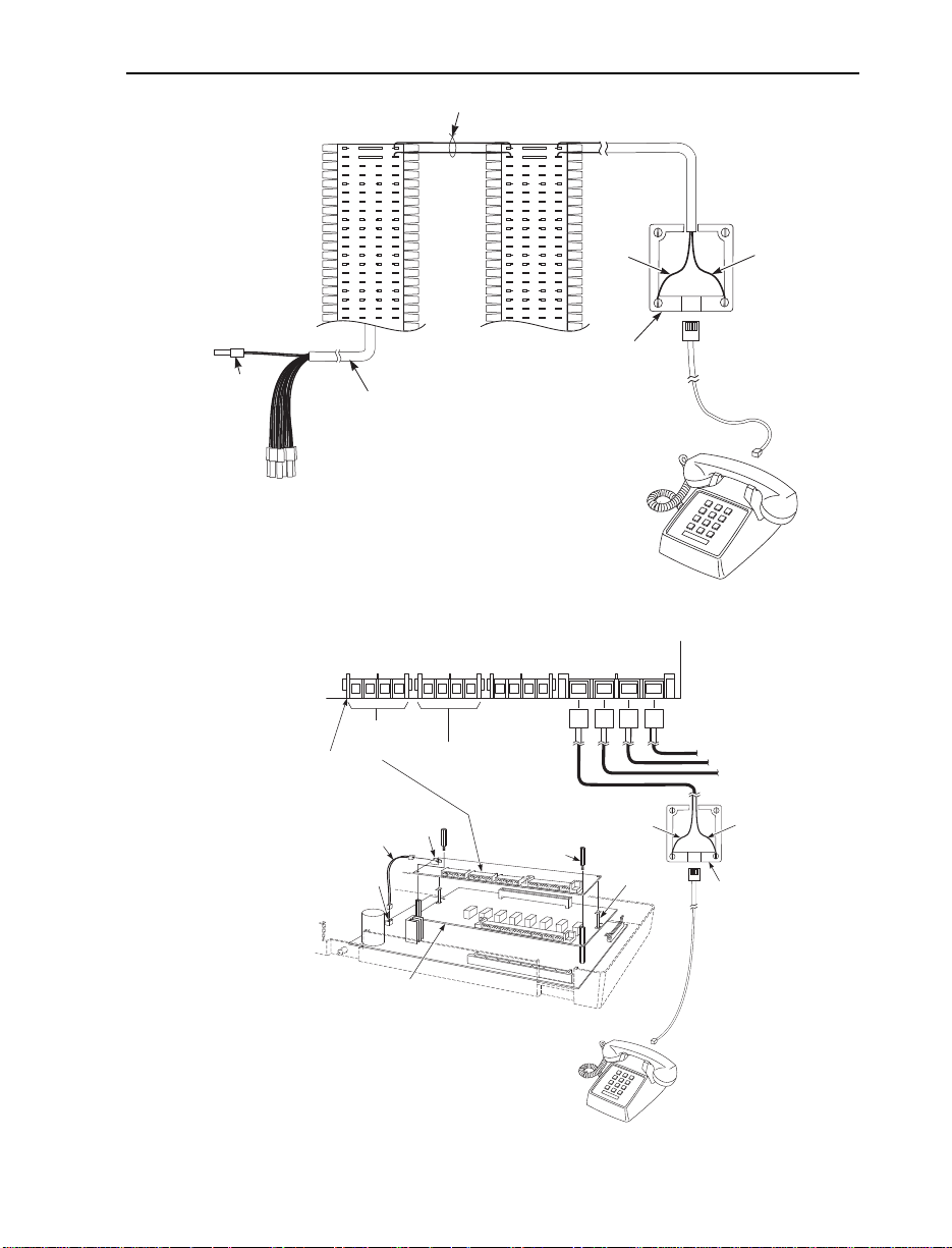
Power Failure Cut-Through (Figure 4-16)
When system AC power fails, the 4 PF XFER PCB automatically
connects up to four trunks to the Power Failure Telephones.
Installing a Power Failure Telephone
1. Plug a 2-pin DDK connector to a COCN connector on the CPU or
2CO/8STA PCB. Plug the other end into a PFCON connector on
the 4 PF XFER PCB.
2. Plug a 2-pin DDK connector to a COCN connector on the 4 PF
XFER PCB. Connect the other end to the 625 modular jack leading to the RJ11C telco jack.
3. Plug a 2-pin DDK connector into the SLTCN connector on the 4
PF XFER PCB. Connect the other end to the auxiliary (C) block.
4. Cross-connect the associated wire pair from the C block to the
cross-connect block.
5. Install a modular jack for the Power Failure Telephone within six
feet of the telephone’s location.
6. Run one-pair of 24 AWG station cable from the cross-connect
block to the Power Failure Telephone modular jack.
7. Terminate the station cable WHT/BLU - BLU/WHT leads to the
GRN and RED lugs in the modular jack.
8. Install bridging clips as required.
9. Plug a line cord into the Power Failure Telephone and the phone’s
modular jack.
No programming is required to enable the Power Failure
Telephone.
To test the Power Failure Telephone:
1. Make sure the Switch-1 on the CPU PCB is set to the right side.
This ensures that your programming and configuration is
retained when you power down the system.
2. Power down the system.
3. At the Power Failure Telephone, lift the handset and place a test call.
The call will go out on the trunk in the 4 PF XFER PCB to
which the telephone is connected.
4-18
Page 51
POWER FAILURE TELEPHONES
625
Modular
Jack
Single Line
Telephone
BLK
YEL
RED
GRN
BLU-WHT
WHT-BLU
82400 - 18
Nylon Spacer
Metal Spacer
CPU
2CO/8STA PCB
4 PF XFER PCB
PFCON
To CO Connection
on CPU Card
To Telco
Connection
COCN PFSTN SLTCN
PFUCN
Attached Wire
PFUCN
625
Modular
Jack
Power
Failure
Telephone
BLKYEL
RED GRN
BLU-WHT
WHT-BLU
One-Pair Cross-Connect
DDK
Connector
To Power Failure
Telephone
connector on
4 PF XFER PCB
25-Pair DDK
Installation Cable
"C" Block
Cross
Connect
Block
82400 - 2
Figure 4-16 CONNECTING A POWER FAILURE TELEPHONE
Figure 4-17 CONNECTING TO THE 4 PF XFER PCB
4-19
Page 52

VOICE MAIL
Using Voice Mail
The Portrait System is compatible with the NVM-202ex, NVM-22
(P/N 17590A), and NVM-2000 Voice Mail Systems. This feature provides telephone users with comprehensive Voice Messaging and Auto
Attendant capabilities. Voice Messaging ends the frustration and cost
of missed calls, inaccurate written messages and telephone tag. Voice
Messaging frees a company’s busy receptionist and secretaries for
more productive work.
The system requires the following:
● Voice Mail Interface Unit (P/N 82440)
Maximum of 4 Voice Mail Interface Units or 8 Voice Mail
ports.
● NVM-202ex (P/N 17670), NVM-22 (P/N 17590A), or NVM-2000
(P/N 17500 or 17510, version 7.0 or higher) Voice Mail Unit
● One of the following Portrait setups:
Setup 1
●
Portrait 824 main cabinet (P/N 82400) with Software version
2.1B or higher and 2CO/8STA PCB (P/N 82402A)
NOTE: The Voice Mail ports must be connected to the
2CO/8STA PCB (P/N 82402A).
OR
Setup 2
●
Portrait 824 main cabinet (P/N 82400A) with Software version
2.1B or higher
NOTE: The Voice Mail ports must be connected to station
ports 1-8.
OR
Setup 3
●
Portrait 824 main cabinet (P/N 82400A) with Software version
2.1B or higher and 2CO/8STA PCB (P/N 82402)
NOTE: The Voice Mail ports must be connected to station
ports 1-8.
To confirm if your equipment can support voice mail, you can also
use Program 93 - Sub-CPU Version in the Portrait system. The ver-
sion number of the CPU (Unit 1), First Expansion PCB (Unit 2), and
Second Expansion PCB (Unit 3) should be “08” or above. If the version number is “04” for any unit, the corresponding equipment can
4-20
Page 53

VOICE MAIL
not support the voice mail option. The following is an example of
what you may see.
Unit 1 (CPU - P/N 82400A) = 08
Unit 2 (First Expansion PCB - P/N 82402) = 04
Unit 3 (Second Expansion PCB - P/N 82402A) = 08
The above indicates that the CPU and Second Expansion PCB can
support voice mail, but it is not supported on the First Expansion
PCB. When connecting the voice mail ports, they would be connected
to either the CPU or the Second Expansion PCB.
Each voice mail port uses an intercom link. The Portrait system provides six intercom links at the default setting. When the voice mail
ports exceed the available intercom links (possible when using the
NVM-202ex or NVM-2000), the Portrait system must be reprogrammed to allow unused line circuits to be used as intercom links.
Otherwise, blocking may occur due to the lack of intercom links. This
can be accomplished in Portrait Program 45 - Intercom Link
Increase.
Installation (Figure 4-18)
1. Using a four-conductor line cord, connect the first Voice Mail port
to “LINE1” on the Voice Mail Interface and the second Voice Mail
port to “LINE2” on the Voice Mail Interface.
NOTE: The two ports for each Voice Mail Interface must be
from the same PCB (e.g., 7 & 8 of the CPU or 15 & 16 of the
2 CO/8 STA PCB).
2. Connect a four-conductor line cord from the Port 1 & 2 jack on the
back of the Voice Mail, to the Voice Mail port on the Voice Mail
Interface.
3. Refer to the Portrait Pocket Guide (P/N 82400PKT**) for required
programming information.
4. Refer to the Voice Mail Manual for further programming.
System
NVM - 22 17590INS** Chapter 1 - Installation
NVM-202ex 17570SWG** Chapter 2 - Starting Up and
Manual P/N See
Chapter 2 - Programming
Installing NVM-202ex
4-21
Page 54
BLK
RED
GRN
BLU-WHT
ORN-WHT WHT-ORN
WHT-BLU
8240 - 62a
YEL
BLK
RED
GRN
BLU-WHT
ORN-WHT
WHT-ORN
WHT-BLU
YEL
BLU-WHT
ORN-WHT
WHT-ORN
WHT-BLU
BLU-WHT
ORN-WHT
WHT-ORN
WHT-BLU
25-Pair Cable
to Portrait KSU
Extension
Modular
Jack
Extension
Modular
Jack
Twisted Pair
Station Cable
VOICE MAIL INTERFACE
VOICE MAIL LINE2 LINE1
4-Conductor
Line Cord
NVM-22
Connector for
Ports 1 and 2
NVM-202ex
Connector for
Ports 1 and 2
VOICE MAIL
Chapter 5 - Customizing
System and Port Options
17570INS** Chapter 3 - Starting Up and
Installing NVM-202ex
4-22
Figure 4-18 CONNECTING THE VOICE MAIL
Page 55

WALL MOUNT KIT
Using the Wall-Mount Kit
You can use a wall-mount kit to attach any key telephone to a wall.
The wall-mount kit includes a mounting bracket, wall-mount screws
and a handset hanger.
Note: The wall-mount kit currently does not accommodate installing
on a wall plate.
A telephone with a DSS console attached can not be wall-
mounted.
Installing the Wall-Mount Handset Hanger (Figure 4-19)
1. Insert the handset hanger in the slot provided beneath the telephone’s hookswitch.
82400 - 34
Handset Hook
Figure 4-19 INSTALLING THE WALL-MOUNT HANGER
4-23
Page 56

WALL MOUNT KIT
82400 - 33
Wall-Mounting a Key Telephone (Figure 4-20)
1. Mount the wall-mount kit’s plastic bracket in the desired location
using the screws provided.
2. Insert the telephone’s line cord from the 625 modular jack through
the plastic bracket using the space provided in the bracket.
4. Place the telephone on top of the plastic bracket on the clips provided.
Gently push the bottom of the bracket in until it snaps into the slots on
the phone.
4-24
Figure 4-20 INSTALLING THE WALL MOUNT BRACKETS
Page 57
Section 5
Specifications and Parts List
In this section . . . Page
Specifications . . . . . . . . . . . . . . . . . . . . . . . . . . . . . . . . . . . . . .5-3
Parts List . . . . . . . . . . . . . . . . . . . . . . . . . . . . . . . . . . . . . . . . . .5-7
5. SPECIFICATIONS AND PARTS LIST
5-1
Page 58

5-2
Page 59

SPECIFICATIONS
System Capacities
Alarm Sensors: 2
Analog Trunks (CO/PBX lines): 8
Cabinets: 1
Caller ID Circuits: 8
Door Boxes: 2
Door Box/Music On Hold Relays: 2
DSS Consoles: 3 max. per system
Electronic Key and/or Analog Telephones: 24
External Paging Zones: 2
Internal Paging Zones: 4
Power Failure Telephones: 4
Speed Dial, Personal: 10
Speed Dial, System: 100
Talk Timeslots (Intercom/line): 6 (expandable)
Tenant Groups: 4
Voice Mail Ports: 8
PCBs
2CO/8STA PCB: 2
Auxillary PCB: 1
CPU Central Processing Unit: 1
4 PF XFER PCB: 1
Ring Generator PCB: 1
SMDR PCB or Caller ID/SMDR PCB 1
Environmental Requirements
Meeting established environmental standards maximizes the life of the system. Refer to the
Standard Practices Manual for further information. Be sure that the site is not:
1. In direct sunlight or in hot, cold or humid places.
2. In dusty areas or in areas where sulfuric gases are produced.
3. In places where shocks or vibrations are frequent or strong.
4. In places where water or other fluids comes in contact with the main equipment.
5. In areas near high-frequency machines or electric welders.
6. Near computers, telexes, microwaves, air conditioners, etc.
7. Near radio antennas (including shortwave).
5-3
Page 60

SPECIFICATIONS
Power Requirements
A dedicated 110 VAC 60 Hz 15 amp circuit (terminated in a NEMA 5-15R receptable) located
within six feet of the cabinet is required. You should install a separate dedicated outlet for each
cabinet.
Environmental Specifications
Cabinets and Key Telephones Door Box
Temperature: 0-45oC (32-113oF) Temperature: -20-60oC (-4-140oF)
Humidity: 10-95% (non-condensing) Humidity: 10-95% (non-condensing)
Electrical Specifications
Power Supply: 110 VAC ±- 10% @ 50-60 Hz 15 amp
Power Requirements: 85 VA-(max 75 W)
.7 Amps
Grounding Requirements: 12 AWG copper wire
5-4
External Paging
Output Impedance: 600 Ohm
Output Level: Nominal 250 mV (-10 dBm)
Maximum Output: 400 mV RMS
Door Box/External Paging Contacts
Contact Configuration: Normally open
Relay Contact: 250 mA @ 24 VDC
Alarm Sensors
Loop Resistance: Less than 100 ohms
Page 61

SPECIFICATIONS
BGM/MOH Music Source Input
Input Impedance: 600 Ohm
Input Level: Nominal 250 mV (-10 dBm)
Maximum Input: 1V RMS
Inputs for MOH and BGM are located on the Auxillary PCB.
FCC Registration Information
Model: Portrait 824
Manufacturer: Nitsuko America
Load Number (DOC): N/A
FCC Part 15 Registration: Class A
Sample FCC Registration Number: 1ZDTHA-12345-MF-E
(Refer to the label on the Main Cabinet for the FCC Registration Number.)
Reg. MTS/WATS Mfrs. Port Ringer SOC Network
Status Interfaces Identifier Eq. Number Jacks
Original 02LS2 NX7NA-408M-A 0.6B 9.0F RJ11C
NX7E-208M
Cabling Requirements
1. Do not run station cable in parallel with the AC source, telex or computer, etc. If the
cables are near cable runs to those devices, use shielded cable with grounded shields or
install the cable in conduit.
2. When cables must be run on the floor, use cable protectors.
3. Cable runs for key telephones, single line telephones and Door Boxes must be a dedicated,
isolated cable pair.
Device Cable Type Cable Run Length (ft) Notes
Key Telephone 2-pair twisted 24 AWG 1000
Single Line 2-wire 24 AWG 3,700 at constant 20 mA
Telephone
Door Box 2-wire 24 AWG 500
5-5
Page 62

SPECIFICATIONS
Mechanical Specifications
Type of Equipment Width Depth Height Weight
Equipment Cabinet 19” 13” 4 1/2” 11 lbs *
(* Base unit with only CPU card installed)
22-Button Display Telephone 6 11/16” 8 11/16” 3 7/16” 1 lb 12 1/2 oz
22-Button Standard Telephone 6 11/16” 8 11/16” 3 7/16” 1 lb 10 1/2 oz
16-Button Standard Telephone 6 11/16” 8 11/16” 3 7/16” 1 lb 10 1/2 oz
24-Button DSS Console 2 1/2” 8 11/16” 2 1/2” 1/2 lb
Door Box 5.28” 4” 1.4” 1/2 lb
5-6
Page 63

PARTS LIST
Station Equipment
Description Part Number
22-Button Display Telephone (Gray) 82473
22-Button Display Telephone (White) 82473W
22-Button Standard Telephone (Gray) 82470
22-Button Standard Telephone (White) 82470W
22-Button Standard Handsfree Telephone (Gray) 82471
22-Button Standard Handsfree Telephone (White) 82471W
16-Button Standard Telephone (Gray) 82460
16-Button Standard Telephone (White) 82460W
ST4 Single Line Telephone (White) 85403W
ST4 Single Line Telephone (Black) 85403B
DSS Console (Gray) 82456
DSS Console (White) 82456W
Wall Mount Kit (Gray) 82479
Wall Mount Kit (White) 82479W
Analog Telephones (customer provided)
Peripheral Station Equipment
Description Part Number
Door Box 92245
Common Equipment
Description Part Number
Cabinet (Includes CPU Central Processing Unit) 82400
Cabinet (Includes CPU Central Processing Unit) with
Voice Mail 82400A
PCBs
Description Part Number
CPU Central Processing Unit Included in 82400
2CO/8STA PCB 82402
2CO/8STA PCB with Voice Mail 82402A
4 PF XFER PCB 82415
Auxiliary PCB 82410
Caller ID PCB 82425
Caller ID/SMDR PCB 82421
Ring Generator PCB 82405
SMDR PCB 82420
5-7
Page 64

PARTS
Handset (Gray) 82496
Handset (White) 82496W
Handset and Cord Assembly (Gray) 82495
Handset and Cord Assembly (White) 82495W
Handset Coil Cord - 6’ (Gray) 82475-6
Handset Coil Cord - 9’ (Gray) 82475-9
Handset Coil Cord - 13’ (Gray) 82475-13
Handset Coil Cord - 6’ (White) 82475-6W
Handset Coil Cord - 9’ (White) 82475-9W
Handset Coil Cord - 13’ (White) 82475-13W
Line Cord - 7’ (Ash) 82476-7
Line Cord - 14’ (Ash) 82476-14
Line Cord - 25’ (Ash) 82476-25
Line Cord - 7’ (White) 82476-7W
Line Cord - 14’ (White) 82476-14W
Line Cord - 25’ (White) 82476-25W
16-Button Display Telephone Plastic C.O. Cover 82488-6
22-Button Display Telephone Plastic C.O. Cover 82488-12
DSS Console Plastic Cover 82488-SDS
Top Directory Plastic Cover 82488-D
Station # Plastic Cover 92600-EN
16-Button Telephone Paper Insert 82489-6
22-Button Telephone Paper Insert 82489-12
DSS Console Paper Insert 82489-SDS
Top Directory Paper Insert 82489-D
Station # Designation Strip 92605-EN
DDK Connectors, 2 pin (qty: 25) 85993
DDK Connectors, 4 pin (qty: 25) 85995
DDK Installation Cable, 4 wire for extension connection 82490
DDK Installation Cable, 2 wire for trunk connection 82492
DDK Installation Cable, 6” 2 wire for power failure
Replacement Parts
Description Part Number
connection 82491
5-8
Page 65

Replacement Parts
Description Part Number
Flying Directory Attachment 82481
Flying Directory Paper Card & Plastic Holder Assembly 82482
Flying Directory Clear Plastic Holder 82483
Flying Directory Paper Card Insert 82484
Flying Directory Card Assembly (Kit) 82480
Consists of: (1) 82481, (1) 82482
Bottom Directory Tray Assembly (Card & Holder) 82485
Bottom Directory Clear Plastic Card Holder 82486
Bottom Directory Paper Card 82487
Door Box/Page Ribbon Cable 82492
Ring Generator Cable 82493
SMDR Connector & Cable Assembly 82494
Music on Hold Disable Connector 82411
Wall Mount Hook 82499
PARTS
5-9
Page 66

PARTS
5-10
Page 67

Nitsuko America, Telecom Division
4 Forest Parkway
Shelton, CT 06484
TEL: 203-926-5400
FAX: 203-929-0535
Other Important Telephone Numbers
Sales: . . . . . . . . . . . . . . . . . . . . . . . . . . . . . . . . . . . . . . . . . .203-926-5450
Customer Service: . . . . . . . . . . . . . . . . . . . . . . . . . . . . . . . .203-926-5444
Customer Service FAX: . . . . . . . . . . . . . . . . . . . . . . . . . . .203-926-5454
Technical Service: . . . . . . . . . . . . . . . . . . . . . . . . . . . . . . . .203-925-8801
Discontinued Product Service: . . . . . . . . . . . . . . . . . . . . . .900-990-2541
Technical Training: . . . . . . . . . . . . . . . . . . . . . . . . . . . . . . .203-926-5430
Emergency Technical Service (After hours) . . . . . . . . . . . .203-929-7920
(Excludes discontinued products)
Page 68

4 Forest Parkway, Shelton, CT 06484
TEL: 203-926-5400 FAX: 203-929-0535
Part No. 82400INS03 May 1998
Issue 1-0 Printed in U.S.A. (183)
 Loading...