

Page 1
NEC
Versa P600
Disassembly Manual
Page 2

Table of contents
Overview.................................................................................................................................................................3
Technician Notes....................................................................................................................................................3
Disassembly Instructions........................................................................................................................................3
Reassembly Instructions ........................................................................................................................................3
Required Tools .......................................................................................................................................................3
Hazardous Voltage .................................................................................................................................................4
Avoid Electrostatic Discharge.................................................................................................................................4
Power Supply Unit..................................................................................................................................................4
Removing the Battery.............................................................................................................................................5
Removing the Hard Disk Drive ...............................................................................................................................5
Removing the MDC Modem Module ......................................................................................................................6
Removing the Keyboard Cover ..............................................................................................................................7
Removing Keyboard...............................................................................................................................................7
Removing the Optical drive & Heat plate ...............................................................................................................8
Removing the Memory Module ............................................................................................................................10
Removing the Wireless Module............................................................................................................................11
Removing Heat Sink & CPU.................................................................................................................................11
Removing the LCD Module ..................................................................................................................................13
Removing the LCD Penal.....................................................................................................................................15
Removing the Top Cover .....................................................................................................................................17
Removing the Touch Pad.....................................................................................................................................18
Removing the DC/DC Board ................................................................................................................................20
Removing the Main Board....................................................................................................................................21
DIP Switch Setting................................................................................................................................................22
Screws..................................................................................................................................................................23
Notice ...................................................................................................................................................................24
NEC Versa P600 Disassembly Manual
Page 2
Page 3

Overview
This document contains step-by-step disassembly instructions for the Versa T400 chassis. The instructions are
illustrated where necessary with images of the part that is being removed or disassembled. Furthermore, the screws
that are removed are shown next to the image of the parts themselves.
NEC reserves the right to make changes to the Versa P600 chassis without notice.
Technician Notes
Only technicians authorized by NEC Computers International BV should attempt to repair this equipment. All
troubleshooting and repair procedures are detailed to allow only subassembly/module level repair. Because of the
complexity of the individual boards and subassemblies, no one should attempt to make repairs at the component
level or to make modifications to any printed wiring board. Improper repairs can create a safety hazard. Any
indication of component replacement or printed wiring board modifications may void any warranty or exchange
allowances.
Disassembly Instructions
When disassembling the system unit, follow these general rules:
Do not disassemble the system into parts that are smaller than those specified in the instructions.
Label all removed connectors. Note where the connector goes and in what position it was installed.
Turn off the power and disconnect all power and all options.
Reassembly Instructions
Reassembly is the reverse of the disassembly process. Use care to ensure that all cables and screws are returned
to their proper positions. Check that no tools or any loose parts have been left inside the chassis. Check that
everything is properly installed and tightened.
Required Tools
All disassembly procedures can be performed using the following tools:
PH 0x60 Philips screwdriver
PH 0x40 Philips screwdriver
4.0 x 60 Flat screwdriver
2.0 x 30 Flat screwdriver
SW5,0 Spacer screwdriver
Small tweezers
NEC Versa P600 Disassembly Manual
Page 3
Page 4

Hazardous Voltage
There is hazardous voltage present inside the computer
when it is connected to an AC supply, even when the
computer’s power switch is off. Exposure to hazardous
voltage could cause personal injury. To avoid risk of injury,
contact an Authorized Service Provider for proper
(un)installation of optional hardware devices.
Avoid Electrostatic Discharge
Electrostatic electricity can easily damage circuit cards and
integrated circuits (ICs). To reduce risk of damage, store
them in protective packaging whenever they are not
installed in your system.
Add-in cards can be extremely sensitive to ESD and always
require careful handling. After removing the card from the
computer, place the card flat on a grounded, static-free
surface, component-side up. Use a conductive foam pad if
available, but not the card wrapper. Do not slide the card
over any surface.
Before you install or remove memory modules, video
memory, disk drives, circuit cards or other devices, protect
them from static electricity. To do so, make sure your
computer’s power switch is OFF. Then, unplug the
computer’s AC power cord. Before picking up the device you
(un)install, you should wear an anti-static wrist wrap
(available at electronic supply stores). Be sure to connect
the wrist wrap to an unpainted metal portion of the computer
chassis. As an alternative, you can dissipate electrostatic
build-up by touching an unpainted metal portion of the
computer chassis with one hand. Then touch the device you
are (un)installing with the other hand, and maintain
continuous contact with it until it is (un)installed in the
computer.
Power Supply Unit
Under no circumstances should you attempt to disassemble
the power supply. The power supply contains no userserviceable parts. Inside the power supply are hazardous
voltages that can cause serious personal injury. Always
return a defective power supply to your dealer.
WARNING
Ensure that the computer is disconnected from
its power source and from all
telecommunications links, networks, or modem
lines whenever the chassis cover is removed.
Do not operate the computer with the cover
removed.
AVERTISSEMENT
Assurez-vous que le système est débranché de
son alimentation ainsi que de toutes les
liaisons de télécommunication, des réseaux, et
des lignes de modem avant d’enlever le capot.
Ne pas utiliser le système quand le capot est
enlevé.
WARNUNG
Das System darf weder an eine Stromquelle
angeschlossen sein noch eine Verbindung mit
einer Telekommunikationseinrichtung, einem
Netzwerk oder einer Modem-Leitung haben,
wenn die Gehäuseabdeckung entfernt wird.
Nehmen Sie das System nicht ohne die
Abdeckung in Betrieb.
ADVERTENCIA
Asegúrese de que cada vez que se quite la
cubierta del chasis, el sistema haya sido
desconectado de la red de alimentación y de
todos lo enlaces de telecomunicaciones, de red
y de líneas de módem. No ponga en
funcionamiento el sistema mientras la cubierta
esté quitada.
WAARSCHUWING
Zorg er voor dat alle verbindingen van en naar
de computer (stroom, modem netwerk, etc)
verbroken worden voordat de behuizing
geopend wordt. Zet de computer nooit aan als
de behuizing geopend is.
AVVERTENZA
Prima di rimuovere il coperchio del telaio,
assicurarsi che il sistema sia scollegato
dall’alimentazione, da tutti i collegamenti di
comunicazione, reti o linee di modem. Non
avviare il sistema senza aver prima messo a
posto il coperchio
NEC Versa P600 Disassembly Manual
Page 4
Page 5
Removing the Battery
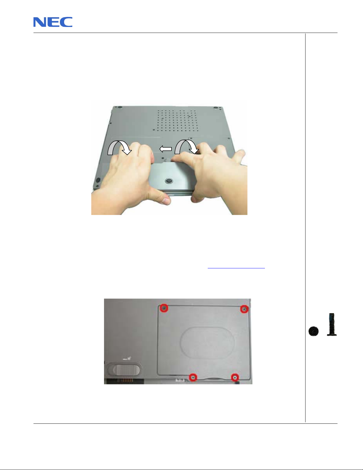
Perform the following steps to remove the battery:
1. Make sure to power off the Versa P600.
2. Turn the unit upside down.
3. Unlock the battery and slide it out of its place as the arrow shows in Fig. 1
Fig. 1 Removing the battery
Removing the Hard Disk Drive
To remove the hard disk drive, first remove the battery (see Removing the Battery), then perform
the following steps:
1. Remove the screws as shown in Fig. 2
M2.5x11 Black
Fig. 2 Removing the Hard disk drive cover
NEC Versa P600 Disassembly Manual
Page 5
Page 6
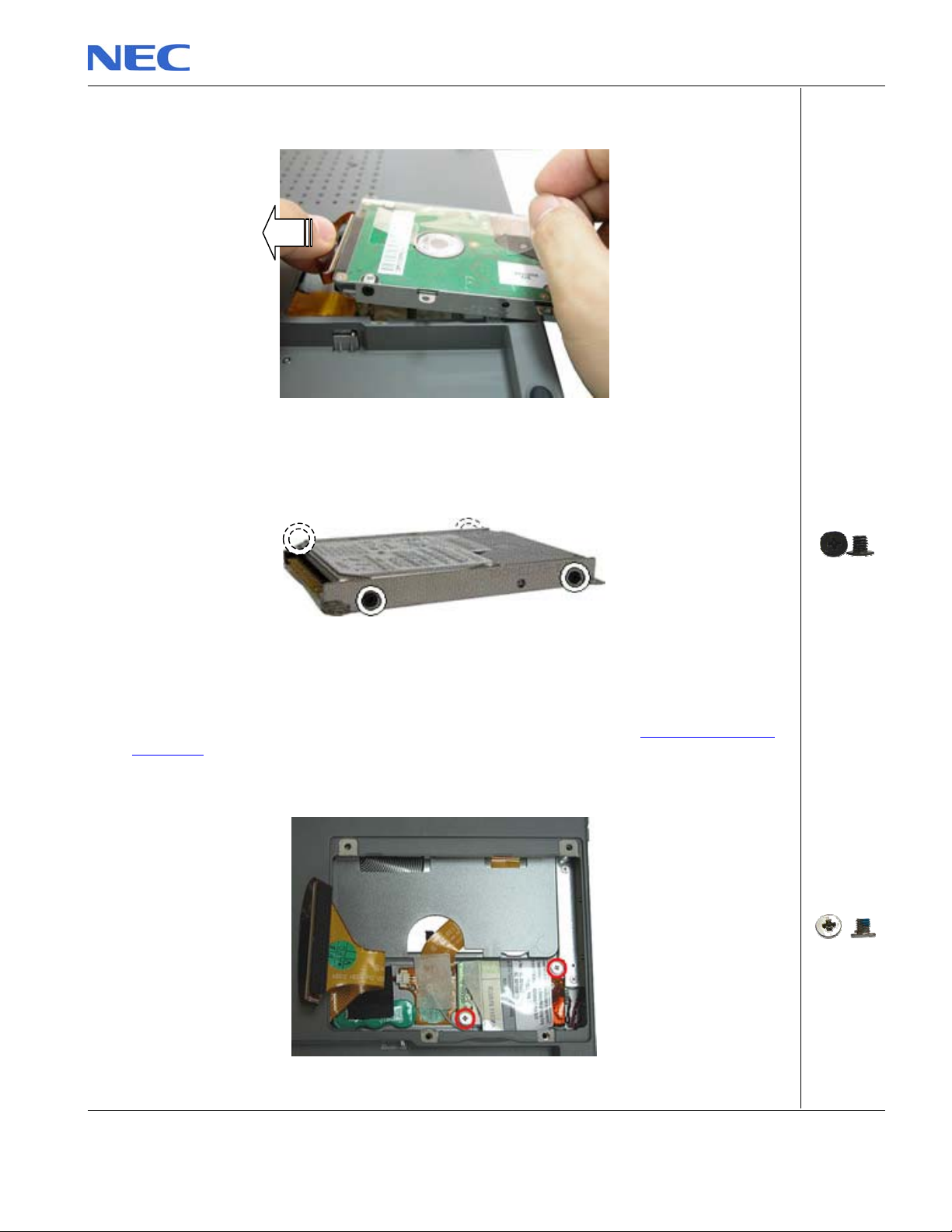
2. Lift up the hard disk drive and disconnect it as shown in Fig. 3
Fig. 3 Disconnecting the hard disk drive
3. Unscrew the four screws on both sides of the hard disk drive as shown in Fig. 4
Fig. 4 Unscrewing the hard disk drive bracket screws
Removing the MDC Modem Module
To remove the MDCmodem module, first remove the hard disk drive (see Removing the Hard
Disk Drive), then perform the following steps:
1. Remove the screw shown in Fig. 5
Fig. 5 Removing the screws on the MCD modem
M3x4 Black
M2.5x3.5 Sliver
NEC Versa P600 Disassembly Manual
Page 6
Page 7
2. Carefully lift up MDC modem module.
3. Disconnect the cable attached to the MDC modem and put the modem aside.
Removing the Keyboard Cover
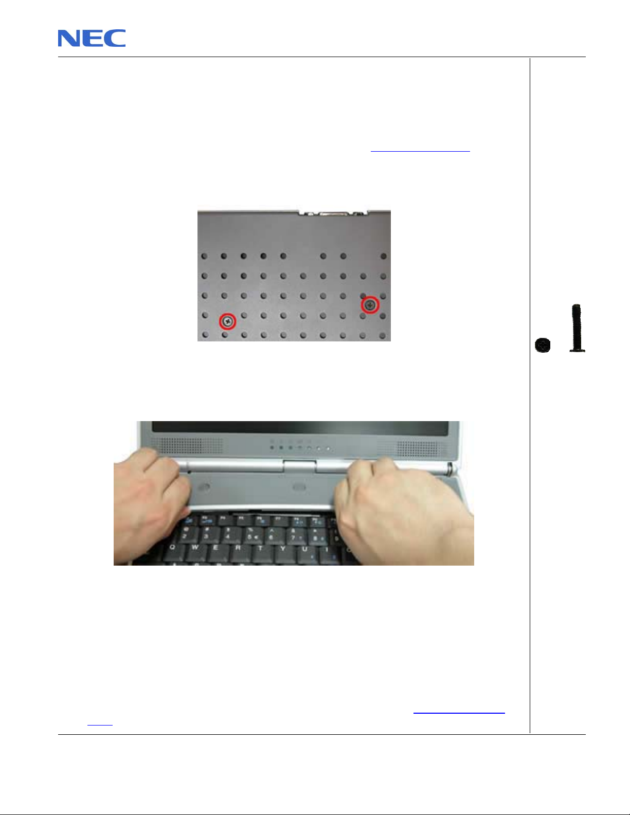
To remove the Keyboard Cover , first remove the battery (see Removing the Battery), then
perform the following steps:
1. Remove the screw as shown in Fig. 6
Fig. 6 Removing Keyboard Cover screws
2. Remove the Keyboard Cover as shown in Fig. 7
Fig. 7 Removing the Keyboard Cover
Removing the Keyboard
To remove the Keyboard module, first remove the keyboard cover (see Removing keyboard
cover), then perform the following steps:
NEC Versa P600 Disassembly Manual
M2x15 Black
Page 7
Page 8
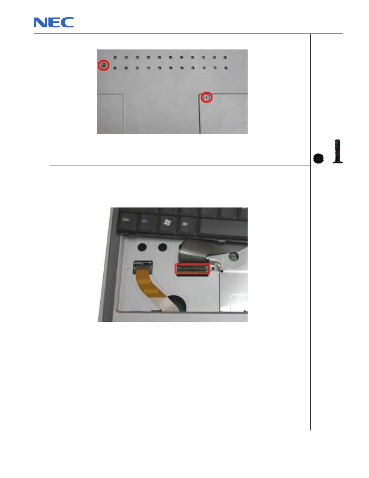
1. Remove the screws as shown in Fig. 8
A
Fig. 8 Removing the screws holding the keyboard
Note: The screw “A” located on the hard disk slot cover holds the hard disk drive and the keyboard.
2. Carefully lift up the keyboard.
3. Release the keyboard FPC cable as shown in Fig. 9 and put the keyboard aside
Fig. 9 Removing the keyboard FPC cable
Removing the Optical drive & Heat plate
To remove the optical drive & heat plate, first remove the keyboard cover (see Removing the
keyboard cover), remove the keyboard (see Removing the keyboard) then perform the following
steps:
1. Remove the screw as shown in Fig. 10
NEC Versa P600 Disassembly Manual
M2.5x11 Black
Page 8
Page 9
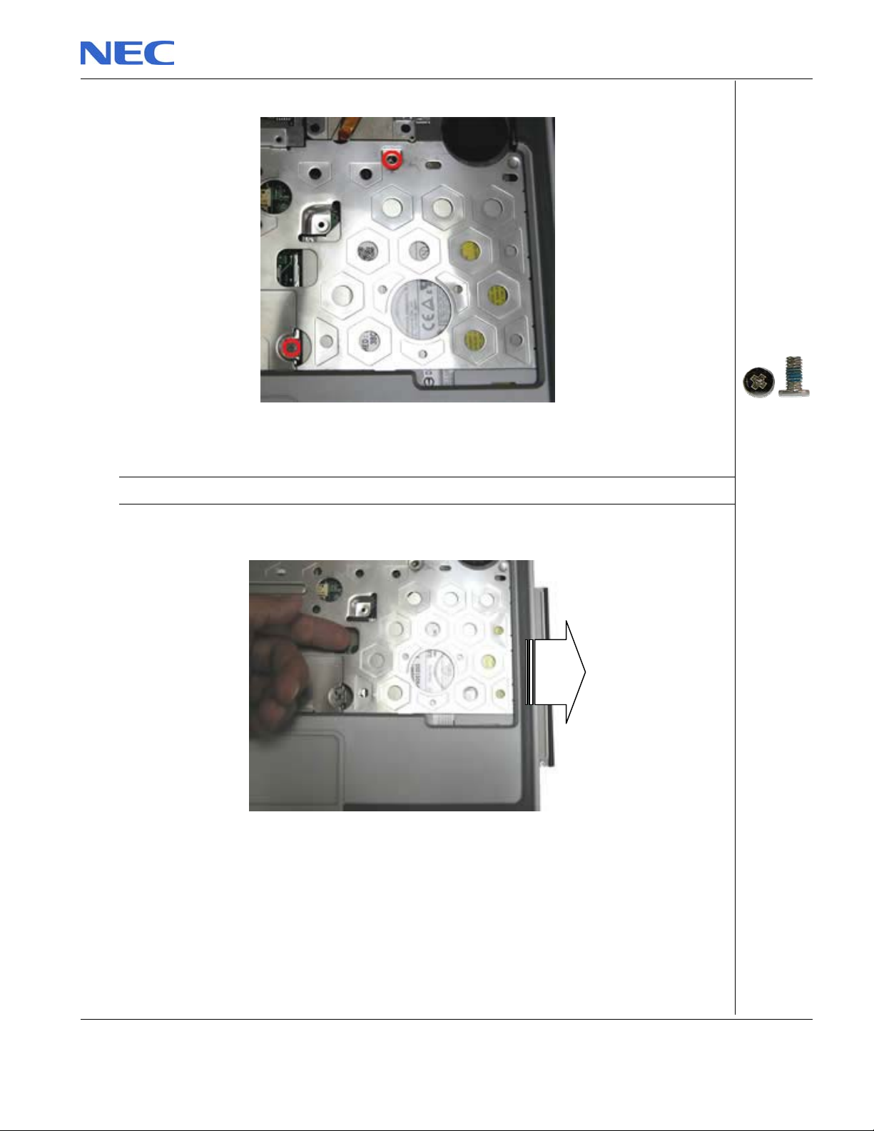
A
Fig. 10 Removing the screws on Heat Plate
Note: If you want to disassemble the Optical Drive, you are required to release Screw “A” only.
2. Push the Optical Drive module out from the base unit as shown in Fig. 11
Fig. 11 Pushing Optical Drive module out from base unit
3. Carefully remove the heat plate from the base unit.
NEC Versa P600 Disassembly Manual
M2.3 x 6 Sliver
Page 9
Page 10
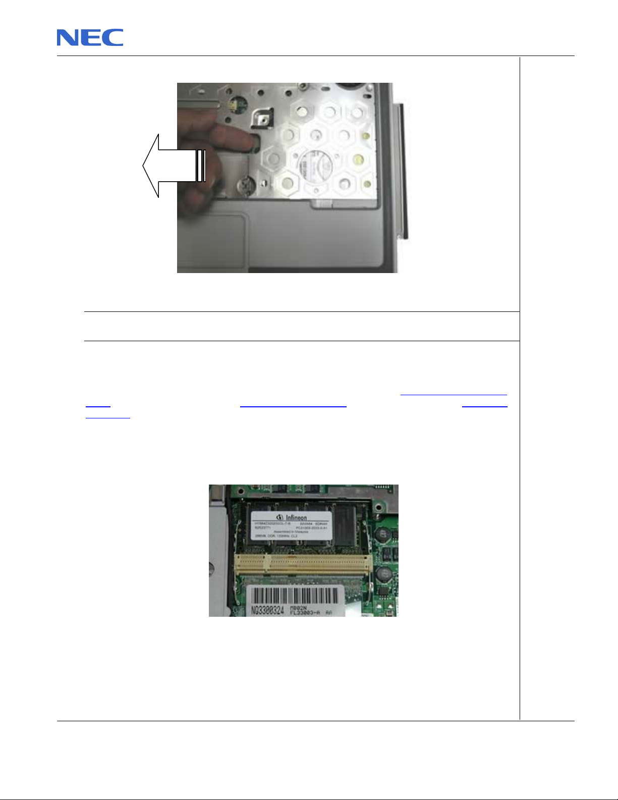
Fig. 12 Removing Heat plate from base unit
Note: When assembling the heat plate, make sure that these three hocks on the heat plate are properly
inserted into the openings located on the top cover.
Removing the Memory Module
To remove the memory module, first remove the Keyboard cover (see Removing the keyboard
cover), remove the keyboard (see Removing the keyboard), remove heat plate (see Removing
heat plate) then perform the following steps:
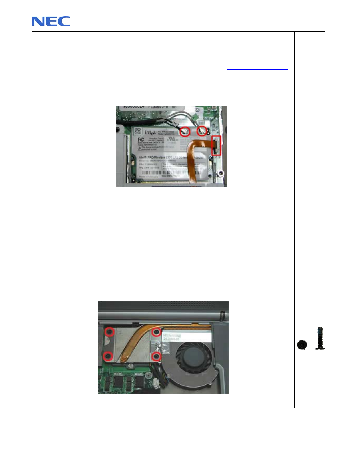
1. Unclip memory module as shown in Fig. 13
Fig. 13 Removing the memory module
2. Remove the Memory Module from its slot and put it aside.
NEC Versa P600 Disassembly Manual
Page 10
Page 11
Removing the Wireless Module
To remove the Wireless Module, first remove the keyboard cover (see Removing the keyboard
cover), remove the keyboard (see Removing the keyboard), remove the heat plate (see
Removing heat plate), then perform the following steps:
1. Disconnect the wireless antenna connectors as shown in Fig. 14
Fig. 14 Disconnecting the wireless antenna
Note: You might consider disconnecting the touch pad flat cable before removing the wireless module.
2. Unclip the wireless module to release it from slot and put it aside.
Removing Heat Sink & CPU
To remove the Heat Sink & CPU, first remove the Keyboard Cover (see Removing the keyboard
cover), remove the keyboard (see Removing the keyboard), remove optical drive & heat plate
(see Removing optical drive & heat plate) then perform the following steps:
1. Release the screws on the heat sink in descending order (4321) as shown in Fig. 15
M2.5x11 Black
NEC Versa P600 Disassembly Manual
Page 11
Page 12
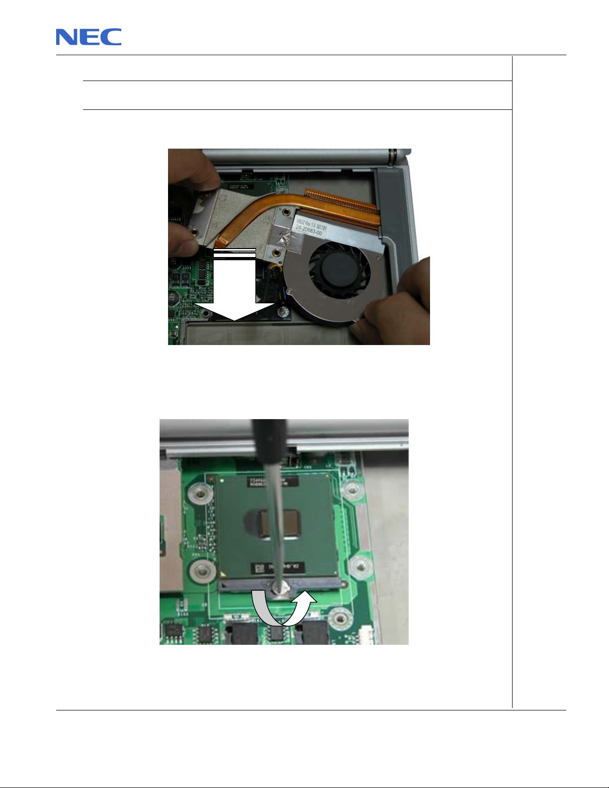
Fig. 15 Releasing the heat sink screws
Note: When assembly the heat sink, tighten the heat sink screws according to the ascending order
(1234). This is to ensure a well distributed pressure over the CPU and to prevent damaging the CPU
2. Carefully remove the heat sink from the CPU socket as shown in Fig. 16
Fig. 16 Removing the heat sink
3. Use flat screws driver to release the CPU from the CPU socket; carefully lift up the CPU and
put it in a safe place.
Fig. 17 Releasing the CPU
NEC Versa P600 Disassembly Manual
Page 12
Page 13
Removing the LCD Module
To remove LCD Module, first remove the Keyboard Cover (see Removing the keyboard cover)
then remove the keyboard (see Removing the keyboard):
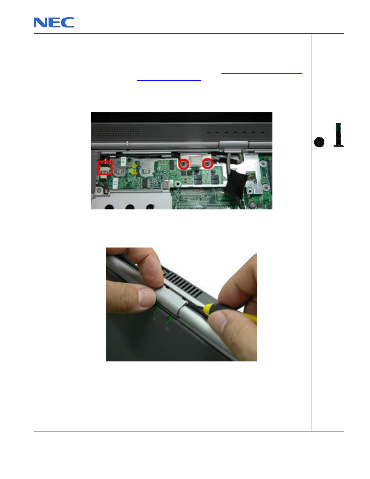
1. Unscrew the two LCD connector screws and also, disconnect the speaker connector as
shown in Fig. 18
Fig. 18 Disconnecting the LCD & speaker connectors
2. Remove the LCD cable cover with a small flat screws driver as shown in Fig. 19 .
Fig. 19 Removing the LCD cable Cover
3. Release the screws at rear side of the unit as shown in Fig. 20
NEC Versa P600 Disassembly Manual
M2.5x11 Black
Page 13
Page 14
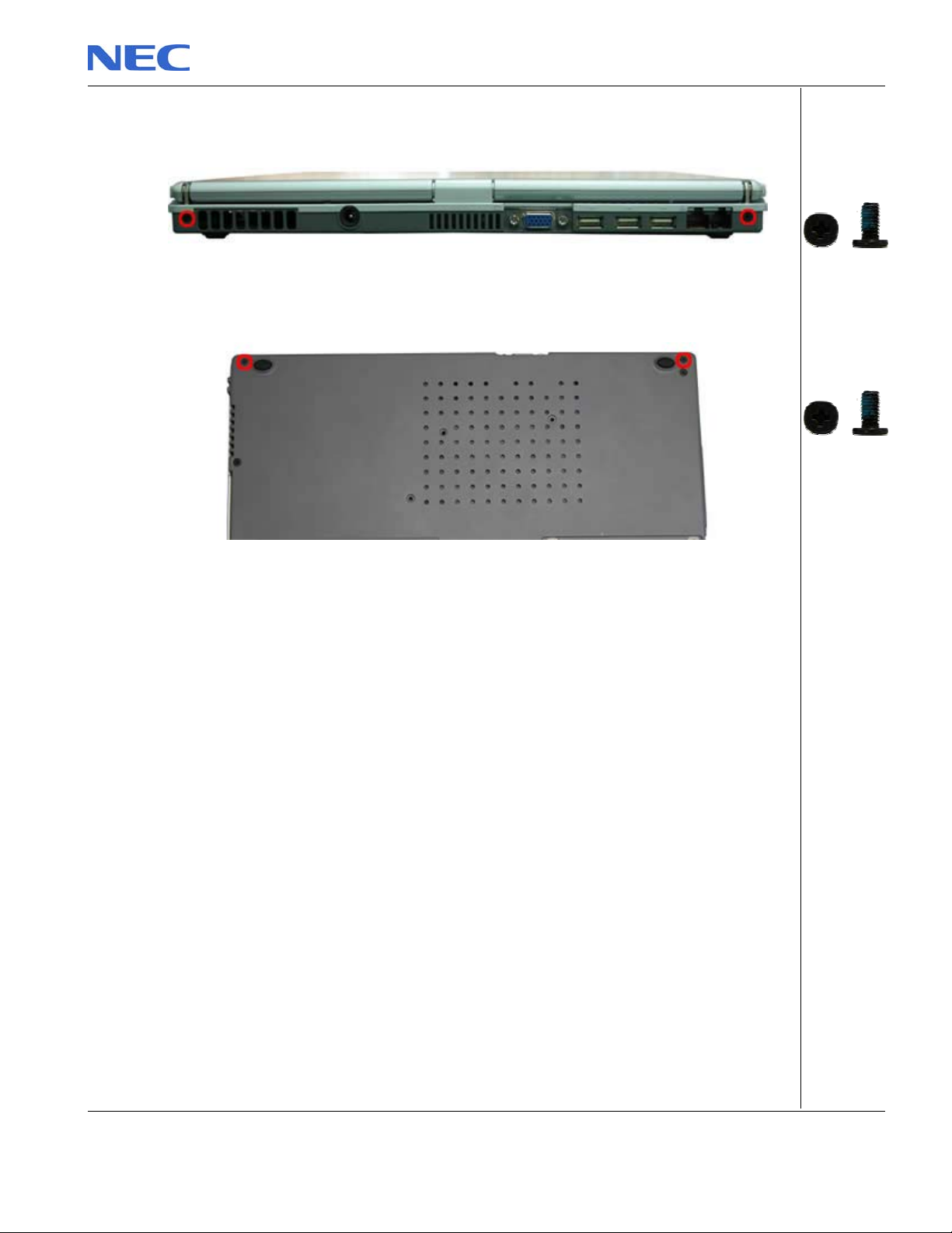
Fig. 20 LCD hinge screws at the rear
4. Unscrew the two screws located on the bottom of the unit as shown in Fig. 21
Fig. 21 LCD hinge screws at the bottom
5. Carefully lift the LCD module out of the system and put it aside.
NEC Versa P600 Disassembly Manual
M2x6 Black
M2x6 Black
Page 14
Page 15
AAA A
Removing the LCD Panel
To remove the LCD Panel, first remove the LCD Module (see Removing the LCD Module), then
perform the following steps:
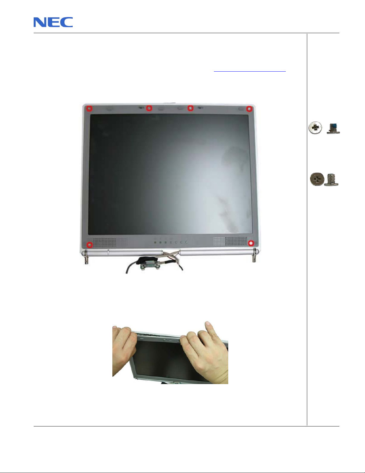
1. Unscrew all screws shown in Fig. 22
BB
Fig. 22 Screws on the LCD Module
2. Release the LCD Bezel carefully and put it aside as shown in Fig. 23
Fig. 23 Removing the LCD Bezel
3. Unscrew all screws encircled in Fig. 24 disconnect the inverter board and put it aside.
NEC Versa P600 Disassembly Manual
A = M2x3.5
Silver
B= M2x5
Silver
Page 15
Page 16
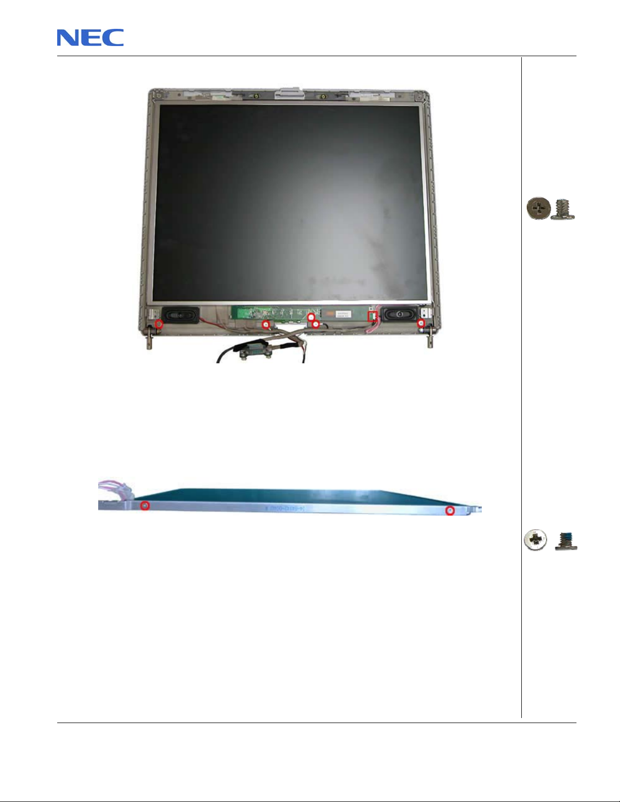
Fig. 24 Removing the inverter board screws
4. Carefully lift up LCD panel and disconnect the LCD cable from the penal.
5. Remove the screws at both sides of the LCD panel in order to release the LCD hinges as
shown in Fig. 25 .
Fig. 25 Removing the LCD Panel hinges
M2x5 Silver
M2x3.5 Silver
NEC Versa P600 Disassembly Manual
Page 16
Page 17
Removing the Top Cover
A
A
A
To remove the Top Cover, first remove the Keyboard Cover (see Removing the keyboard cover),
remove the keyboard (see Removing the keyboard), remove the LCD module (see Removing the
LCD Module) then perform the following steps:
1. Disconnect the MIC connector on the DC/DC board.
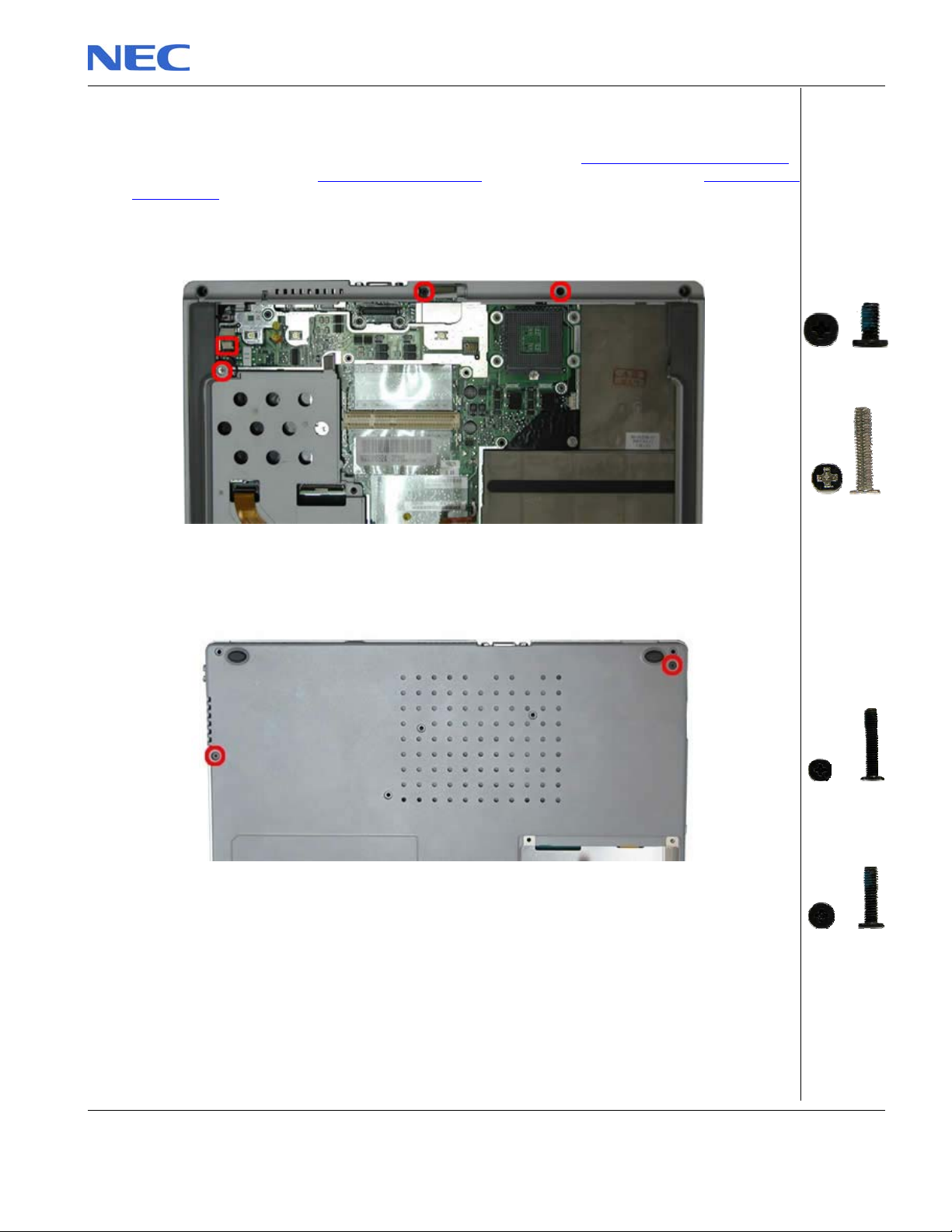
2. Release all screws shown in Fig. 26
B
Fig. 26 Removing the Top cover screws
3. Flip over the unit and remove the screws as shown in Fig. 27
A = M2x6
Black
B = M2.5x12.5
Silver
B
A = M2x15
Black
Fig. 27 Removing the Top cover screws on the bottom of the system
4. Remove all screws in the battery compartment as shown in Fig. 28
B = M2.5x11
Black
NEC Versa P600 Disassembly Manual
Page 17
Page 18
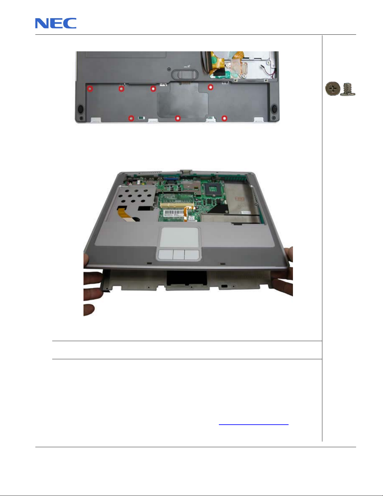
Fig. 28 Battery Compartment
5. Carefully lift up and release the top cover and put it aside.
Fig. 29 Removing the top cover
Note: Remember to disconnect the touch pad cable before lifting up the top cover. On the VGA connector
area use extra care to release the top cover.
Removing the Touch Pad
To remove the Touch Pad, first remove the Top Cover (see Removing the Top Cover), then
perform the following steps:
M2x3 Sliver
NEC Versa P600 Disassembly Manual
Page 18
Page 19
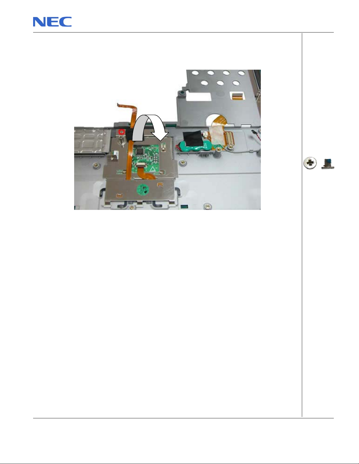
1. On the other side of the top cover unscrew the two screws on the Touch Pad assembly as
shown in Fig. 30 and remove the Touch Pad assy from the palm rest.
Fig. 30 Touch Pad Assembly
NEC Versa P600 Disassembly Manual
M2x3.5 Silver
Page 19
Page 20
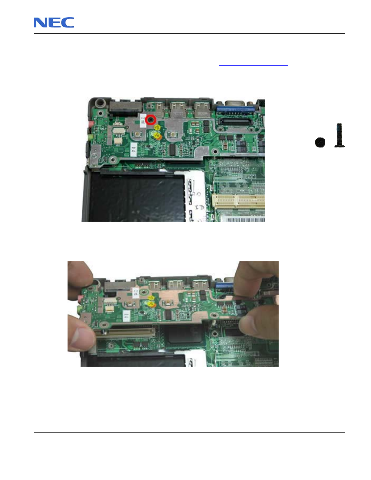
Removing the DC/DC Board
To remove the DC/DC board, first remove the Top Cover (see Removing the Top Cover), then
perform the following steps:
1. Remove the screw on the DC/DC board as shown in Fig. 31
Fig. 31 DC/DC Board
2. Carefully remove the DC/DC board as shown in Fig. 32 and put it aside.
Fig. 32 Removing the DC/DC Board
NEC Versa P600 Disassembly Manual
M2.5x11 Black
Page 20
Page 21
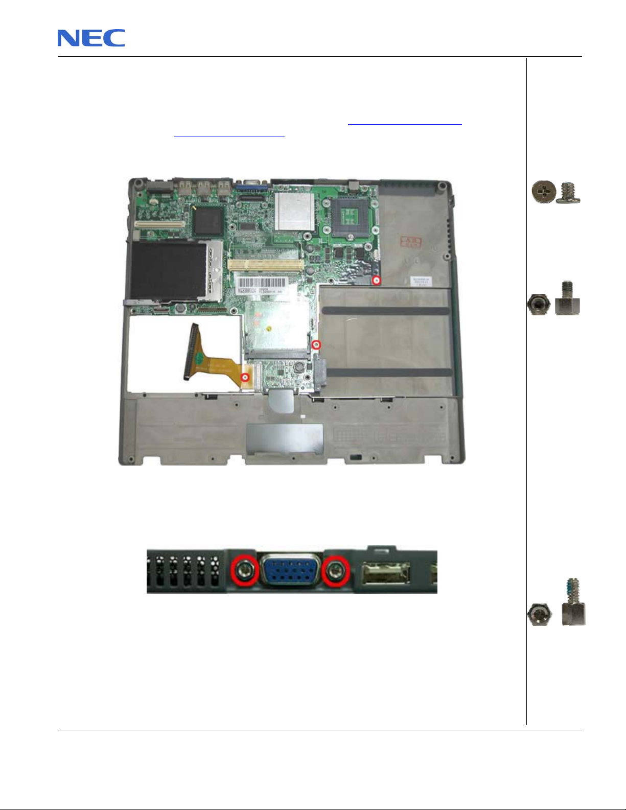
ABA
Removing the Main Board
To remove the Main board, first open the Top Cover (see Removing the Top Cover), remove
DC/DC board (see Removing DC/DC board) then perform the following steps:
1. Remove the screws holding the main board in place as shown in Fig. 33
Fig. 33 Removing the main board screws
2. Disconnect the VGA connector from the base as shown in Fig. 34
A = M2x5
Silver
B = M2.5x8
Silver
Fig. 34 Disconnecting the VGA connector
M2.5x10 silver
3. Lift the main board out of the system and put it aside (Fig. 35 ).
NEC Versa P600 Disassembly Manual
Page 21
Page 22
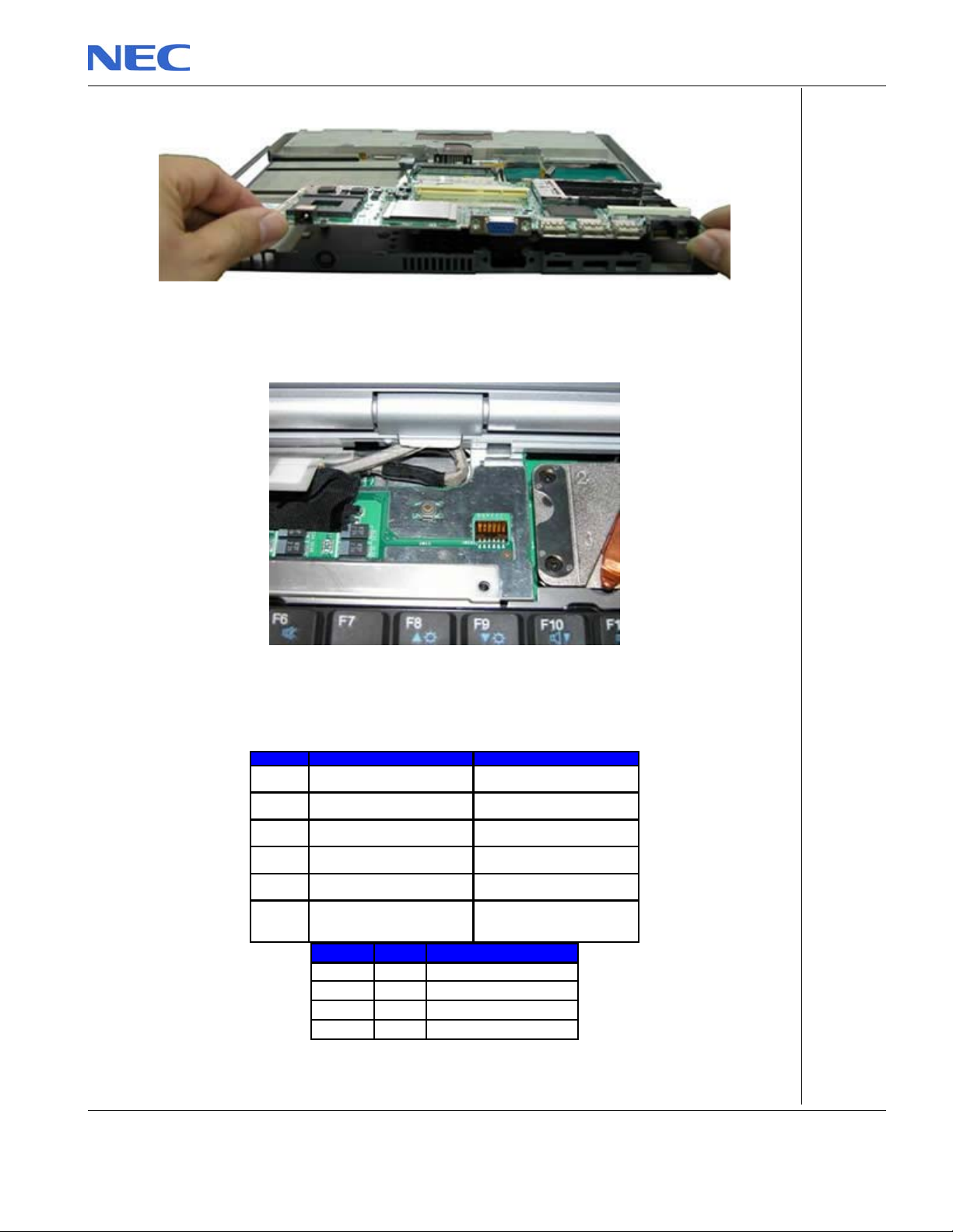
y
DIP Switch Setting
Fig. 35 Removing Main Board
Fig. 36 DIP Switch position
Dip Switch Description Seeting
Bit1
Bit2
Bit3
Keyboard
Select1
Keyboard
Select2
Reserved Reserved
BIOS CrisisBit4
DVDSELBit5
PasswordBit6
Refer to the below table
Refer to the below table
ON : Enable
OFF: Normal (Default)
ON : connect to GND
OFF : NC
Password override.
ON: Override
OFF: Available (factory setting)
Bit 1 Bit 2 Keyboard code
OFF OFF US Ke
board
ON OFF JP Keyboard
OFF ON Reserved
ON ON UK Keyboard
NEC Versa P600 Disassembly Manual
Page 22
Page 23
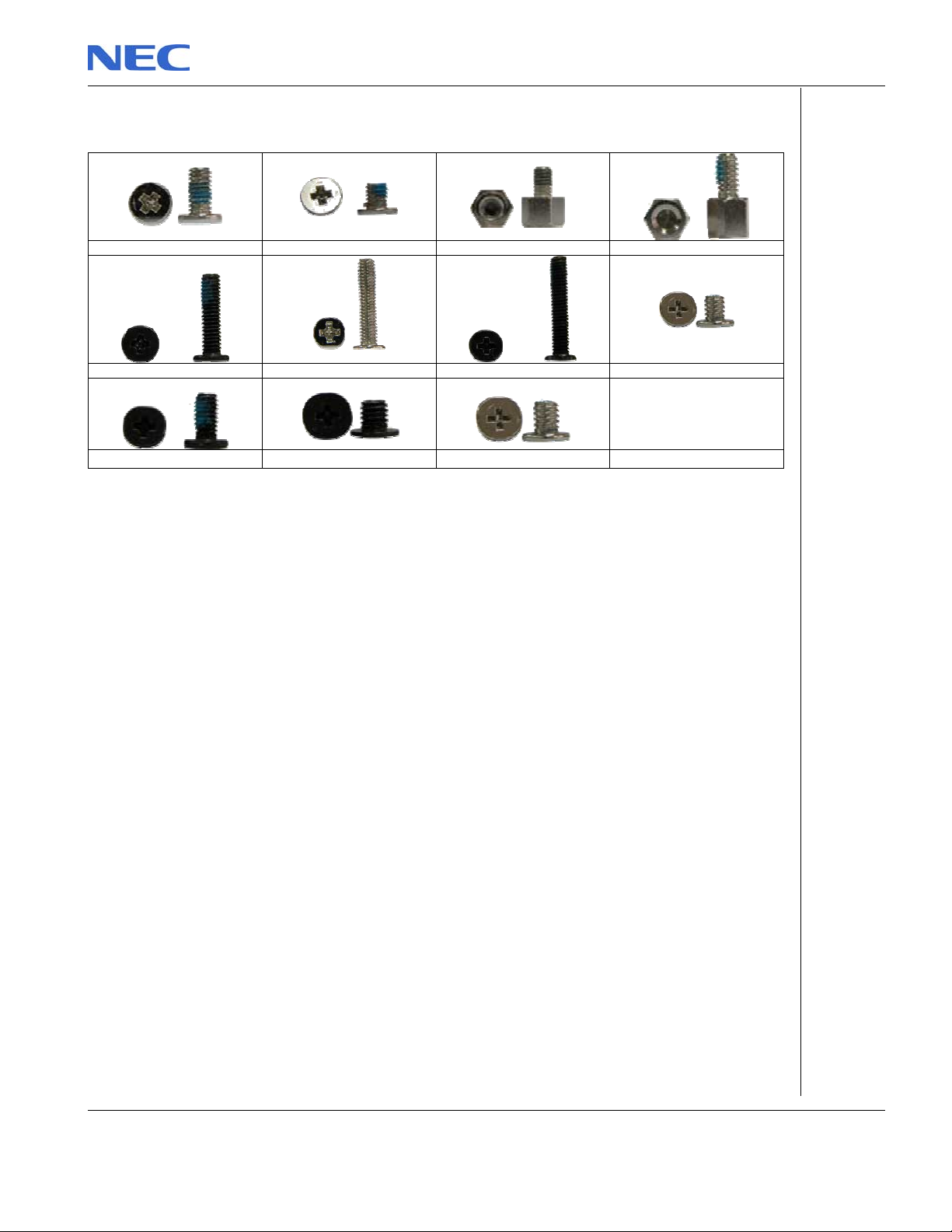
Screws
M2.5x5.6 Silver M2.5x3.5 Silver M2.5x8 Sliver M2.5x10 Silver
M2.5x11 Black M2.5x12.5 Silver M2.5x15 Black M2x3 Sliver
M2x6 Black M3x4 Black M2.5x5 Sliver
NEC Versa P600 Disassembly Manual
Page 23
Page 24

Notice
The information in this guide is subject to change without notice.
This guide contains information protected by copyright. No part of this guide may be photocopied or reproduced in
any form or by any means without prior written consent from NEC Computers International BV.
NEC COMPUTERS INTERNATIONAL BV SHALL NOT BE LIABLE FOR TECHNICAL OR EDITORIAL ERRORS
OR OMISSIONS CONTAINED HEREIN; NOR FOR INCIDENTAL OR CONSEQUENTIAL DAMAGES RESULTING
FROM THE FURNISHING, PERFORMANCE, OR USE OF THIS MATERIAL.
Copyright © 2003 NEC Computers International BV. All rights reserved.
NEC is a trademark of NEC Computers International BV.
The names of actual companies and products mentioned herein may be trademarks and/or registered trademarks
of their respective owners.
Versa P600 Disassembly Manual
Author: Allen Koay
First Edition: May 2003
Document Part Number:
Version: 1.0
NECCM
A division of NEC Computers International BV
NEC Versa P600 Disassembly Manual
Page 24
 Loading...