

NEC NVM-2000 Installation Manual

NVM-2000
Installing an Expansion Drive
Part No. 17511MINS01
Issue 1-0, June 2001

This manual has been developed by NEC America, Inc. It is intended for the use of its customers and service personnel, and should be read in its entirety before attempting to install or program the system. Any comments or suggestions for improving this manual would be appreciated. Forward your remarks to:
NEC America, Inc., Corporate Networks Group
4 Forest Parkway
Shelton, CT 06484
Attention: Manager, Technical Publications
Nothing contained in this manual shall be deemed to be, and this manual does not constitute, a warranty of, or representation with respect to, any of the equipment covered. This manual is subject to change without notice, and NEC
America has no obligation to provide any updates or corrections to this manual. Further , NEC America also reserves
the right, without prior notice, to make changes in equipment design or components as it deems appropriate. No representation is made that this manual is complete or accurate in all respects, and NEC America shall not be liable for
any errors or omissions. In no event shall NEC America be liable for any incidental or consequential damages in connection with the use of this manual. This document contains proprietary information that is protected by copyright.
All rights are reserved. No part of this document may be photocopied or reproduced without prior written consent of
NEC America.
2001 by NEC America. All Rights Reserved
Printed in U.S.A.

◆
Table of Contents
Installing an Expansion Drive . . . . . . . . . . . . . . . . . . . . . . . . . . . . . . . . . . . . . .1
Introduction . . . . . . . . . . . . . . . . . . . . . . . . . . . . . . . . . . . . . . . . . . . . . . . . . . . . . . . . . . . . . . . . . . . . . . . . 1
Tools and Materials Needed . . . . . . . . . . . . . . . . . . . . . . . . . . . . . . . . . . . . . . . . . . . . . . . . . . . . . . . . . . . . 1
Install the Drive . . . . . . . . . . . . . . . . . . . . . . . . . . . . . . . . . . . . . . . . . . . . . . . . . . . . . . . . . . . . . . . . . . . . . 1
Write the Hardware Settings for the New Drive to CMOS . . . . . . . . . . . . . . . . . . . . . . . . . . . . . . . . . . . 10
Determine the Proper Procedure for Writing to CMOS . . . . . . . . . . . . . . . . . . . . . . . . . . . . . . . . . . . 10
Issue 1-0
i

Table of Contents
ii ◆
Issue 1-0
◆
Install the Drive Installing an Expansion Drive
Y
Introduction
This supplement provides instructions for installing an expansion (slave) drive in the NVM-2000
Tools and Materials Needed
ESD Wrist Strap (to be worn on wrist and attached to a grounded metal object at all times)
■
Phillips-head screw driver
■
Diagonal cutters
■
Monitor and keyboard connected to NVM
■
Expansion Hard Drive with two U brackets
■
Install the Drive
Do not turn off the NVM without first shutting it down. If you do not shut
down first, you may corrupt the NVM database when you turn it off.
Installing an Expansion Drive
Install the Drive
WARNING
To install the expansion drive:
Note: Instructions assume you are using the Full Screen Editor.
1. From the Main Menu , select Exit .
2. Type the system password and press <Enter> .
3. Select Shutdown Voice Mail System to shut down the Voice Mail.
4. At the prompt, Are you sure you want to SHUT DOWN the Voice Mail System (Y/N)? , enter
.
5. After the Voice Mail shuts down, turn off the system power and remove the power cord.
6. Remove the monitor cord and the keyboard cord from the NVM cabinet.
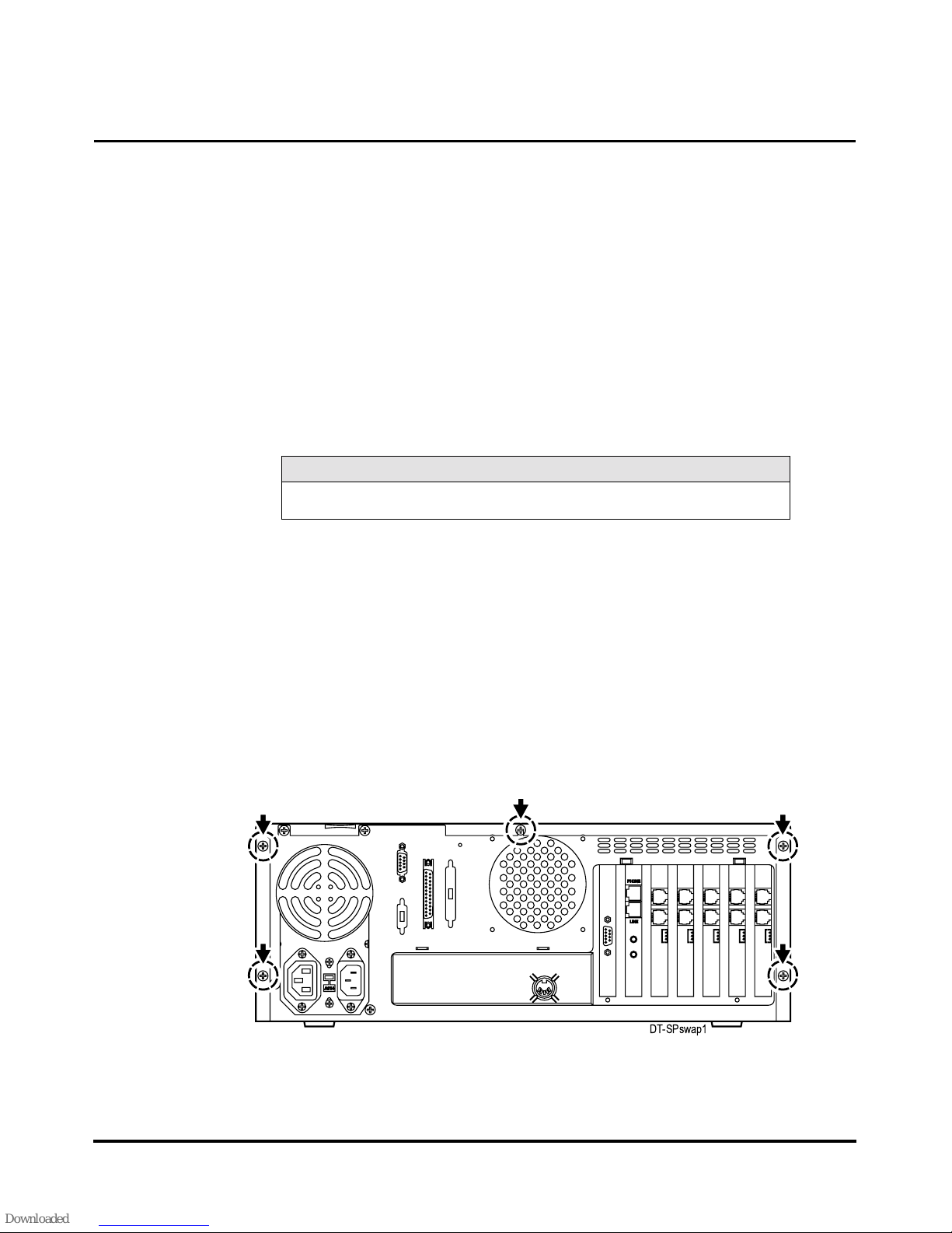
7. From the rear of the cabinet, remove the 5 hex-head scre ws that secure the cover to the cabinet.
See Figure 1. (The back of your cabinet may appear differently from the one shown).
Issue 1-0
DT-SPswap1
Figure 1
1
2
Installing an Expansion Drive
Install the Drive
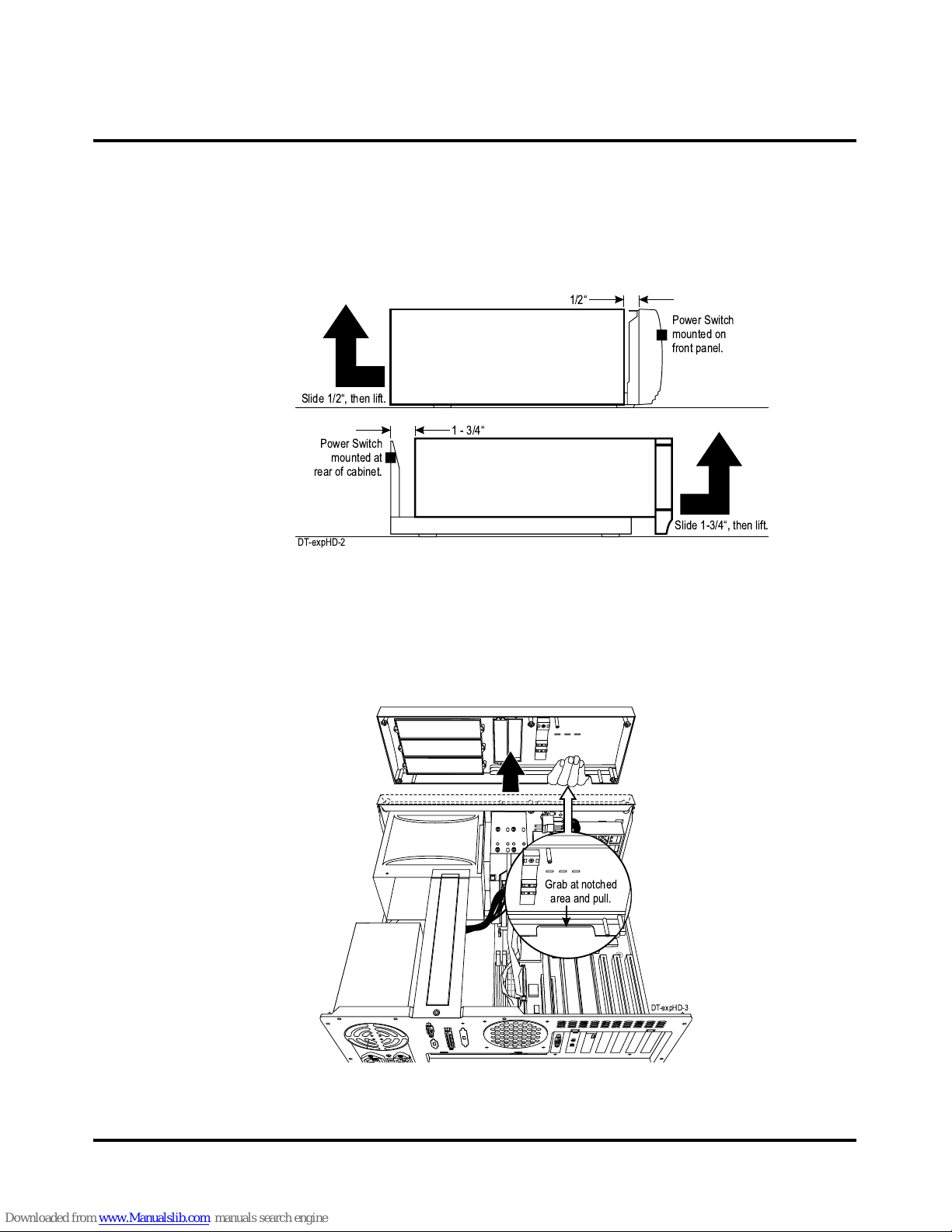
8. Remove the cabinet cover as follows:
If the power switch on your cabinet is mounted on the rear of the cabinet (above the po wer
●
supply vent fan), slide the cover/front panel assembly 1 3/4 inches to w ards the front of the
cabinet, and lift up. See Figure 2.
If the power switch on your cabinet is mounted on the front panel, slide the cover 1/2 inch
●
towards the rear of the cabinet and lift up. See Figure 2.
Slide 1/2, then lift.
1/2
Power Switch
mounted on
front panel.
Power Switch
mounted at
rear of cabinet.
DT-expHD-2
1 - 3/4
Slide 1-3/4, then lift.
Figure 2
9. On many styles of desktop cabinets, the front panel would have been remo v ed when you lifted
off the cabinet cover. If your front panel is removed, go to step 9. If it is still attached:
Do not remove the front panel if it is secured to the cabinet with screws. Go to step 9.
●
If your front panel is secured to the cabinet with 5 metal spring clips:
●
Grab the notch located beneath the front panel (on the end where the logo is located)
■
and firmly pull the front panel away from the chassis. See Figure 3.
◆
Grab at notched
area and pull.
DT-expHD-3
Figure 3
Issue 1-0
 Loading...