

NEC NP62, NP41 - XGA DLP Projector, NP41, NP61 Installation Manual
NEC Display Solutions of America, Inc.
NP41/61/62 Installation Guide
Ceiling Mounted and Desktop Rev 1.1
Contents
Product Description, Lens Specs, Notes and Formulas Pg 1
Diagrams & Distance Charts
Cabinet Dimensions
Ceiling Mount Dimensions
Input Panel and Control Codes
Product Description
Type: .55 DDR DMD™ projector Dimensions: 9.7”(W) x 3.9”(H) x 7.1”(D)
Weight: NP41/NP61: 3.5 lbs
NP62: 3.7 lbs
Resolution: 1024 x 768 Brightness: NP41: 2300 Lumens
Fan Noise: 37 dB / 32 dB @ 1 meter NP61: 3000 Lumens
NP62: 3000 Lumens
Power Consumption: NP41: 265W (max) BTU’s: NP41: 900 BTU/hour
NP61: 285W (max) NP61: 970 BTU/hour
NP62: 300W (max) NP62: 1020 BTU/hour
Lens Specifications
Throw Ratio: 1.8 – 2.2 (for 100” diagonal) Focal Length: 20.4 –24.5mm
Offset Angle: 12.3° - 14.8° (for 100” diagonal) F/#: 2.2 – 2.34
Screen Sizes: 30” - 300” diagonal (4:3) Manual Zoom/Power Focus (w/autofocus)
Notes
For screen sizes not indicated on the projection tables, use the formulas below.
If the figures on the tables do not match the results of formulas, use the figures in the table.
All calculations are based on a 4:3 aspect ratio.
Distances are in inches, for millimeters multiply by 25.4.
Distances may vary 5%.
Formulas
The Projection Formulas use the image width for calculation. For proper projection placement, determine the image width
for the desired screen size. Use the Screen Formulas below to calculate all screen dimensions. Plug in the width for “W” in
the Projection Formulas.
Refer to the diagrams and charts for popular screen sizes on page 2:
Definitions: 4:3 Screen Formulas:
W = Image Width W = H x 4/3
H = Image Height (size) H = W x 3/4
B = Vertical distance between lens center and screen center Screen Diagonal = W x 5/4
C = Throw distance
D = Vertical distance between lens center and screen top
(screen bottom for desktop application)
Projection Formulas:
B = 0.481W
C (wide) = 1.830W –0. 600
C (tele) = 2.203W – 0.800
D = 0.115W
α (wide) = tan¯¹ (B/C(wide))
α (tele) = tan¯¹ (B/C(tele))
______________________________________________________________________________________________________________________
www.necdisplay.com
NP41/61/62 Page 1 of 6
Pg 2
Pg 3-4
Pg 5
Pg 6
NEC Display Solutions of America, Inc.
NP41/61/62 Installation Guide
Ceiling Mounted and Desktop Rev 1.1
Diagrams and Distance Charts
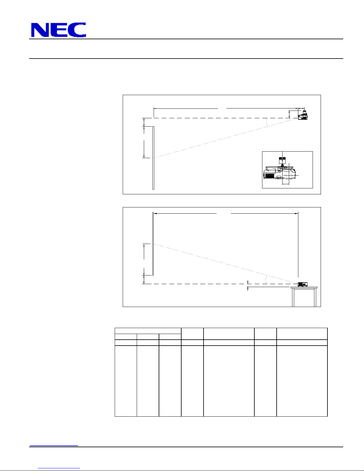
The following diagrams show the relationship between projector position and the screen. Refer to the chart below for data.
Distances are in inches. For millimeters multiply by 25.4.
Ceiling Mounted
Lens Ctr
D
Screen Top
B
C
Throw Distance
5.71"
Screen Ctr
N
C
E
Desktop
C
Throw Distance
Screen Ctr
B
Lens Ctr
D
Screen Bottom
2.28"
Distance Chart for po
pular 4:3 screens
Sc
Diagonal Width Height wide - tele wide - tele
inch inch inch inch inch
33 26 20 13 - 57 3 - 12.6
60 48 36 23 87 - 104 5 14.9 - 12.4
72 58 43 28 104 - 126 6 14.9 - 12.4
84 67 50 32 122 - 147 7 14.8 - 12.4
90 72 54 35 131 - 157 8 14.8 - 12.4
100 80 60 38 145 - 175 8 14.8 - 12.3
120 96 72 46 174 - 210 10 14.8 - 12.3
150 120 90 58 219 - 263 13 14.7 - 12.3
180 144 108 69 263 - 317 15 14.7 - 12.3
200 160 120 77 292 - 352 17 14.7 - 12.3
260 208 156 100 380 - 458 22 14.7 - 12.3
300 240 180 115 439 - 529 25 14.7 - 12.3
reen Size BD
C α
inch degree
Note:
For screen sizes not indicated on the projection table, use the formulas on page 1.
Lens Offset From
Mount Pipe
1.95"
4.75"
______________________________________________________________________________________________________________________
www.necdisplay.com
NP41/61/62 Page 2 of 6
 Loading...