

NEC NP30UCM Installation Manual
INSTALLATION MANUAL
NP30UCM
Versatile Projector Mount
Model: NP30UCM
EUROPE
9530-005-021-05
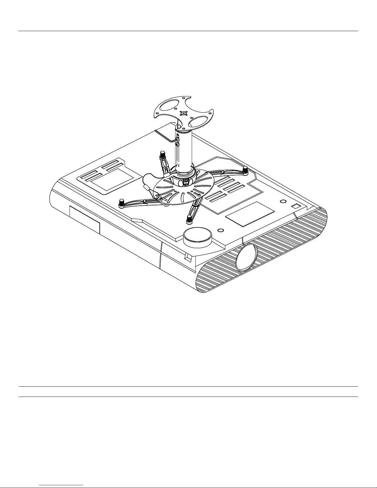
Congratulations on the purchase of your new NP30UCM Versatile Projector Mount. The NP30UCM features our exclusive
SpiroLock™ Technology, which provides the installer with quicker installation times and peace of mind. To truly appreciate the
speed, style and versatility of the NP30UCM, please read this installation manual completely.
Table of Contents
Warning Statements .............................................................................................................................................................................. - 2 -
Parts List ............................................................................................................................................................................................... - 3 -
Installation Tools .................................................................................................................................................................................. - 3 -
Features ................................................................................................................................................................................................. - 4 -
Selecting the Proper Mounting Hardware ............................................................................................................................................. - 4 -
Safety Locking Tab Operation .............................................................................................................................................................. - 5 -
Attaching the Mount ............................................................................................................................................................................. - 5 -
Single Mounting Point Installation ....................................................................................................................................................... - 7 -
Ceiling Installation ................................................................................................................................................................................ - 7 -
Solid Surface Installation ...................................................................................................................................................................... - 7 -
Connecting the Collar Assembly .......................................................................................................................................................... - 8 -
Height Adjustment .............................................................................................................................................................................. - 10 -
Disconnecting the Collar Assembly .................................................................................................................................................... - 10 -
Technical Specifications ..................................................................................................................................................................... - 11 -
Warranty ................................................................................................................................................... Error! Bookmark not defined.
Warning Statements
NEC DOES NOT WARRANT AGAINST DAMAGE CAUSED BY THE USE OF ANY NEC PRODUCT FOR PURPOSES OTHER THAN THOSE
FOR WHICH IT WAS DESIGNED OR DAMAGE CAUSED BY UNAUTHORIZED A TTACHMENTS OR MODIFICATIONS, AND IS NOT
RESPONSIBLE FOR ANY DAMAGES, CLAIMS, DEMANDS, SUITS, ACTIONS OR CAUSES OF ACTION OF WHATEVER KIND
RESULTING FROM, ARISING OUT OF OR IN ANY MANNER RELATING TO ANY SUCH USE, ATTACHMENTS OR MODIFICATIONS.
THE CEILING STRUCTURE MUST BE CAPABLE OF SUPPORTING MORE THAN 30Kg. IF NOT, THE CEILING STRUCTURE M UST BE
REINFORCED. PROPER INSTALLATION PROCEDURE BY A QUALIFIED SERVICE TECHNICIAN, AS OUTLINED IN THE
INSTALLATION INSTRUCTIONS, MUST BE ADHERED TO. FAI LURE TO DO SO C OULD RESUL T IN SERIOUS PER SONAL INJURY, OR
EVEN DEATH.
SAFETY MEASURES MUST BE PRACTICED AT ALL TIMES DURING THE INST ALLATION OF THIS PRODUC T. USE PROPER SAF ETY
GEAR AND TOOLS FOR THE INSTALLATION PROCEDURE TO PREVENT PERSONAL INJURY.
THE MAXIMUM WEIGHT PROJECTOR THAT CAN BE USED WITH THIS MOUNT IS 30Kg. EXCEEDING THIS WEIGHT LIMIT COULD
CAUSE DAMAGE TO THE MOUNT, TO THE PROJECTOR OR TO YOURSELF.
PRIOR TO THE INSTALLATION OF THIS PRODUCT, THE INSTALLATION INSTRUCTIONS SHOULD BE READ AND COMPLETELY
UNDERSTOOD. THE INSTALLATION INSTRUCT IONS MUST BE READ TO PREVENT PERSONAL INJURY AND PROPERTY DAM AGE.
KEEP THESE INSTALLATION INSTRUCTIONS IN AN EASILY ACCESSIBLE LOCATION FOR FUTURE REFERENCE.
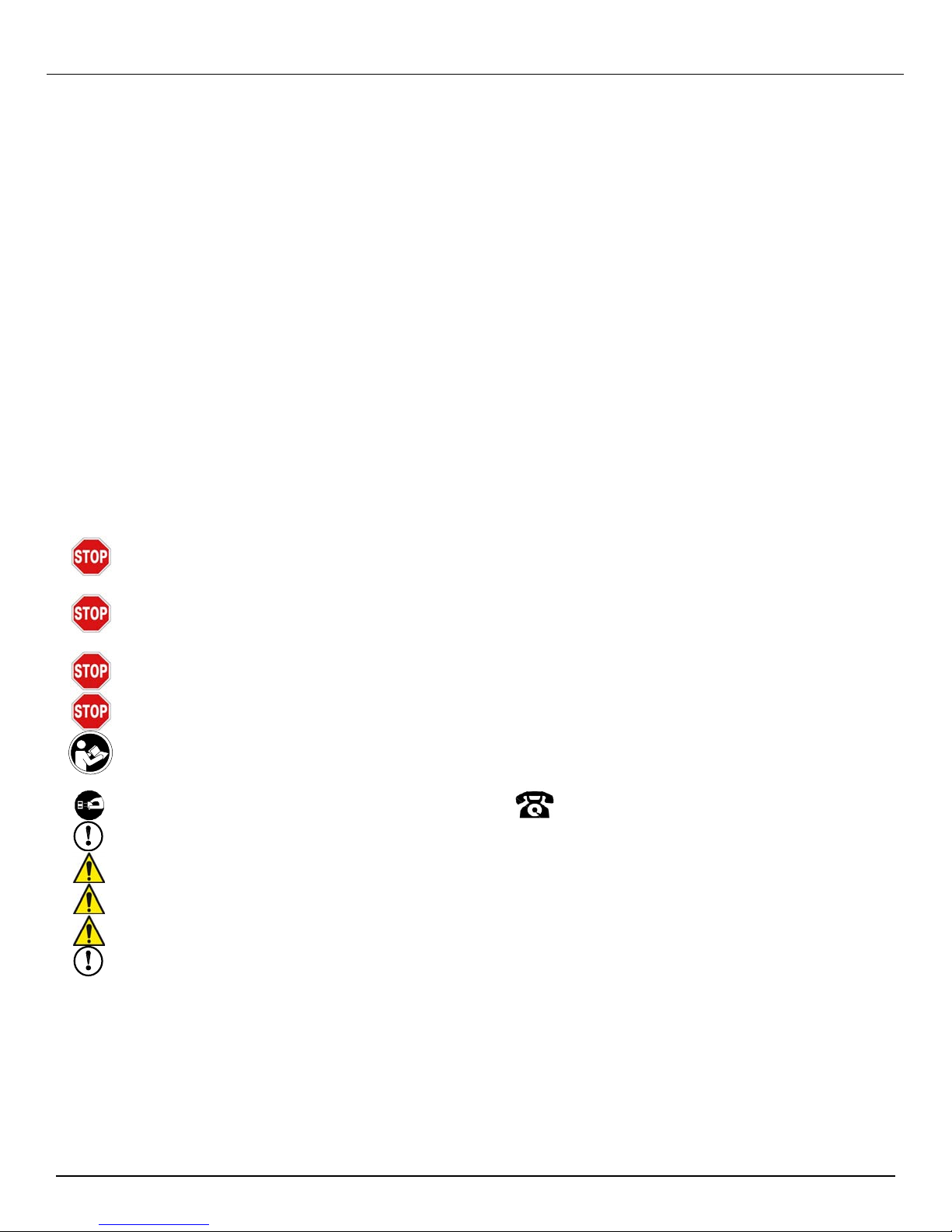
Indicates that the power plug is to be disconnected from the
power outlet.
Safety precautions must be taken at all times.
Warning and Caution statements.
Do not install on a structure that is prone to vibration, movement or chance of impact. Failure to do so could result in damage to the projector and/or
damage to the mounting surface.
Do not install near heater, fireplace, direct sunlight, air conditioning or any other source of direct heat energy. Failure to do so may result in damage to
the projector and could increase the risk of fire.
A qualified person should perform the installation procedure. Injury and/or damage can result from dropping or mishandling the projector
Contact Premier Mounts with any questions –
Customer Service –
+44 (0) 2476 614700
Page - 2 - Installation Manual
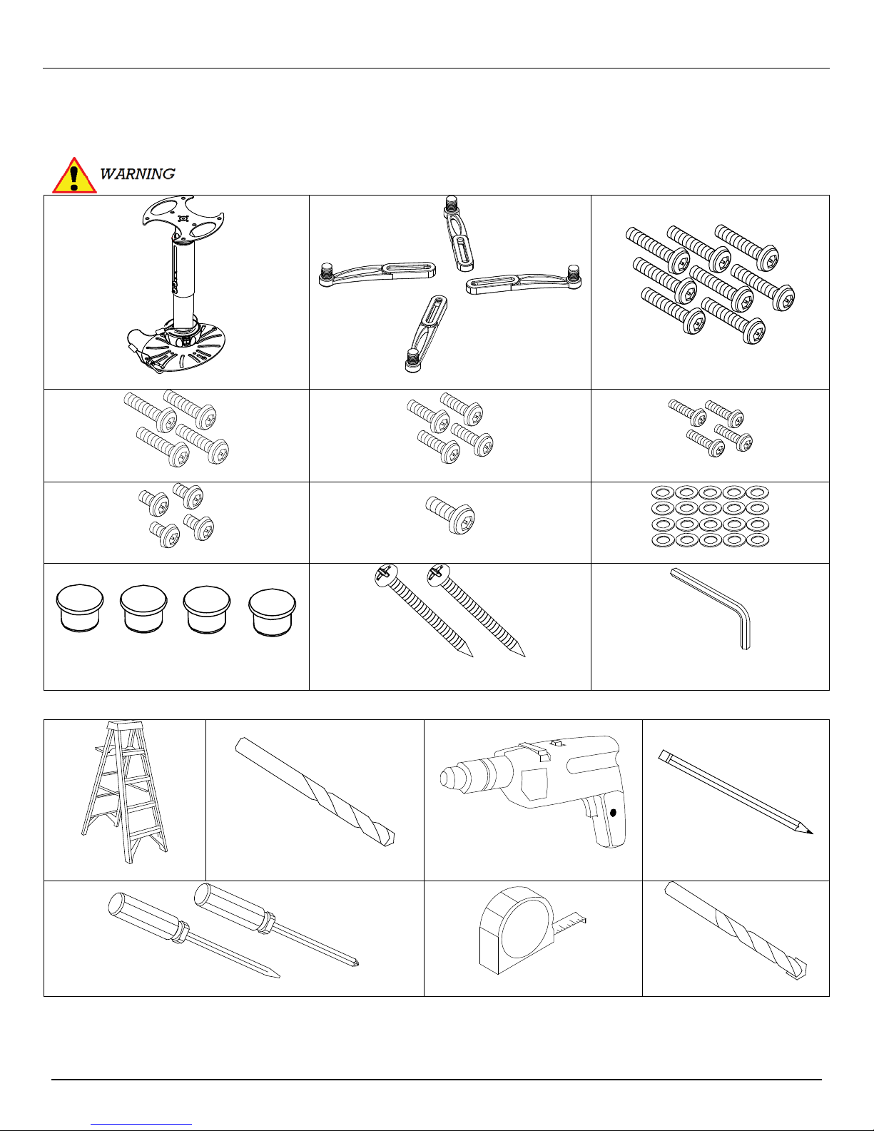
Parts List
Unpack the NP30UCM Mount and familiarize yourself with the components. Before proceeding, the collar assembly must be
separated (please refer to Disconnecting the Collar Assembly, page 10). Please take time before you install the NP30UCM to
determine the location of where the NP30UCM will be mounted. Please familiarize yourself with all components contained herein.
Please review all WARNING and CAUTION statements (see Page 2) before beginning the installation of
the NP30UCM.
NP30UCM Mount (Qty 1) Mounting Legs (Qty 4) M6 x 12mm Security Screw (Qty 8)
M5 x 12mm Security Screw (Qty 4) M4 x 12mm Security Screw (Qty 4) M3 x 16mm Security Screw (Qty 4)
M2.5 X 8mm Security Screw (Qty 4) ¼ – 20 x 5/16” Security Screw (Qty 1) M3 Flat Washers (Qty 20)
Plastic Barrel Caps (Qty 4) #14 x 2” Wood Screws (Qty 2)
M5 Security Allen Wrench –Supplied
(Qty 1)
Installation Tools
W
o
o
d
/
S
t
e
e
l
Ladder Wood Drill Bit Drill Pencil
Flat Tip
Screwdrivers Tape Measure Concrete Drill Bit
Installation Manual Page - 3 -
PhillipsHead
C
o
n
c
r
e
t
e
B
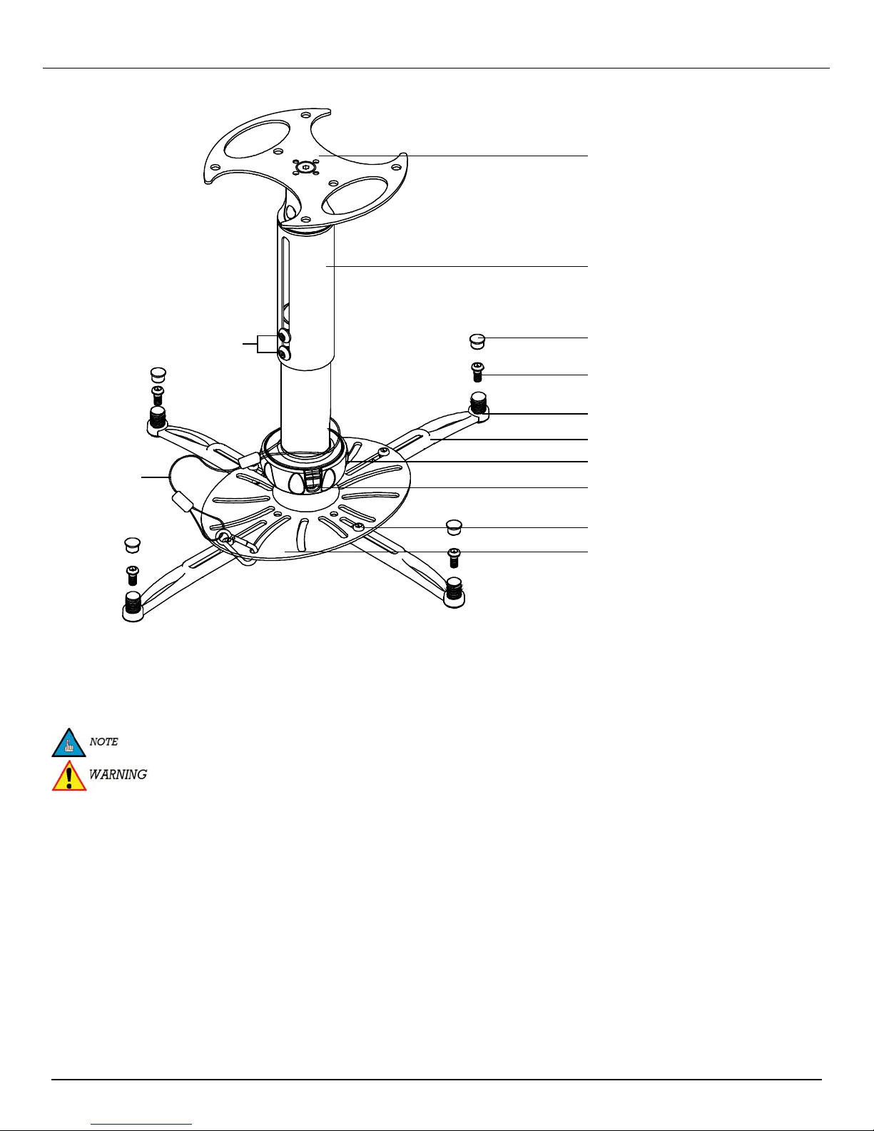
Features
CEILING PLATE
EXTENSION NECK
EXTENSION NECK
LOCKING SCREWS
SAFETY CABLE
AND C LAMP
PLASTIC CAP
MOUNTING HARDWARE
LEVELING BARREL
MOUNTING LEG
COL LAR ASSEMBL Y
SECURITYSAFETYLOCKI NG TA
L EG ASSEMBLY
MOUNTING HARDWARE
MOUNTING PLATE
Selecting the Proper Mounting Hardware
1. Turn the projector over and locate the mounting points.
2. Test each size of the screws provided.
3. The correct screws should thread easily into the mounting point and not pull out when pressure is applied.
The optional M3 flat washers may be used to decrease the screw depth of either the M2.5 x 8mm screws or the
M3 x 16mm screws.
DO NOT OVERTIGHTEN YOUR MOUNTING SCREWS TO THE PROJECTOR CHASSIS. USING THE
INCORRECT SCREW DEPTH MAY CAUSE DAMAGE TO YOUR PROJECTOR.
Page - 4 - Installation Manual
 Loading...