

NEC NP115-R, NP110, NP115, NP215 - XGA DLP Projector, NP216 Installation Manual
...
NEC Display Solutions of America, Inc.
NP110/115/215/216 Installation Guide
Ceiling Mounted and Desktop Rev 1.0
Contents
Product Description, Lens Specs, Notes and Formulas Pg 1
Diagrams & Distance Charts
Cabinet Dimensions
Ceiling Mount Dimensions
Input Panels and Control Codes
Product Description
Type: 1-chip DLP projector, Brightness: NP110: 2200 ANSI Lumens
0.55” DLP NP115: 2500 ANSI Lumens
Resolution: NP110/115: 800 x 600 NP215/NP216: 2500 ANSI Lumens
NP215/NP216: 1024 x 768 Fan Noise: 34dB / 31dB @ 1 meter
Dimensions: 12.2” (W) x 3.7” (H) x 9.7” (D) Weight: NP110/115/215: 5.5 lbs
NP216: 5.7lbs.
Power Consumption: 242W (max) BTU’s: 825 BTU/hour
Lens Specifications
Throw Ratio: 1.9 – 2.1:1 (for 100” diagonal) Focal Length: 21.8mm – 24.0mm
Offset Angle: 12.7° - 14.0° (for 100” diagonal) F/#: 2.41 - 2.55
Screen Sizes: 30” - 300” diagonal (4:3) Manual Focus/Manual Zoom
Notes
For screen sizes not indicated on the projection tables, use the formulas below.
If the figures on the tables do not match the results of formulas, use the figures in the table.
All calculations are based on a 4:3 aspect ratio.
Distances are in inches, for millimeters multiply by 25.4.
Distances may vary 5%.
Formulas
The Projection Formulas use the image width for calculation. For proper projection placement, determine the image width
for the desired screen size. Use the Screen Formulas below to calculate all screen dimensions. Plug in the width for “W” in
the Projection Formulas.
Refer to the diagrams and charts for popular screen sizes on page 2:
Definitions: 4:3 Screen Formulas:
W = Image Width W = H x 4/3
H = Image Height (size) H = W x 3/4
B = Vertical distance between lens center and screen center Screen Diagonal = W x 5/4
C = Throw distance
D = Vertical distance between lens center and screen top
(screen bottom for desktop application)
Projection Formulas:
B = 0.487W
C (wide) = 1.94W
C (tele) = 2.165W
D = 0.112W
α (wide) = tan¯¹ (B/C(wide))
α (tele) = tan¯¹ (B/C(tele))
www.necdisplay.com NP110/115/215/216 Page 1 of 7
Pg 2
Pg 3-5
Pg 6
Pg 7
d
inch
inch
NEC Display Solutions of America, Inc.
NP110/115/215/216 Installation Guide
Ceiling Mounted and Desktop Rev 1.0
Diagrams and Distance Charts
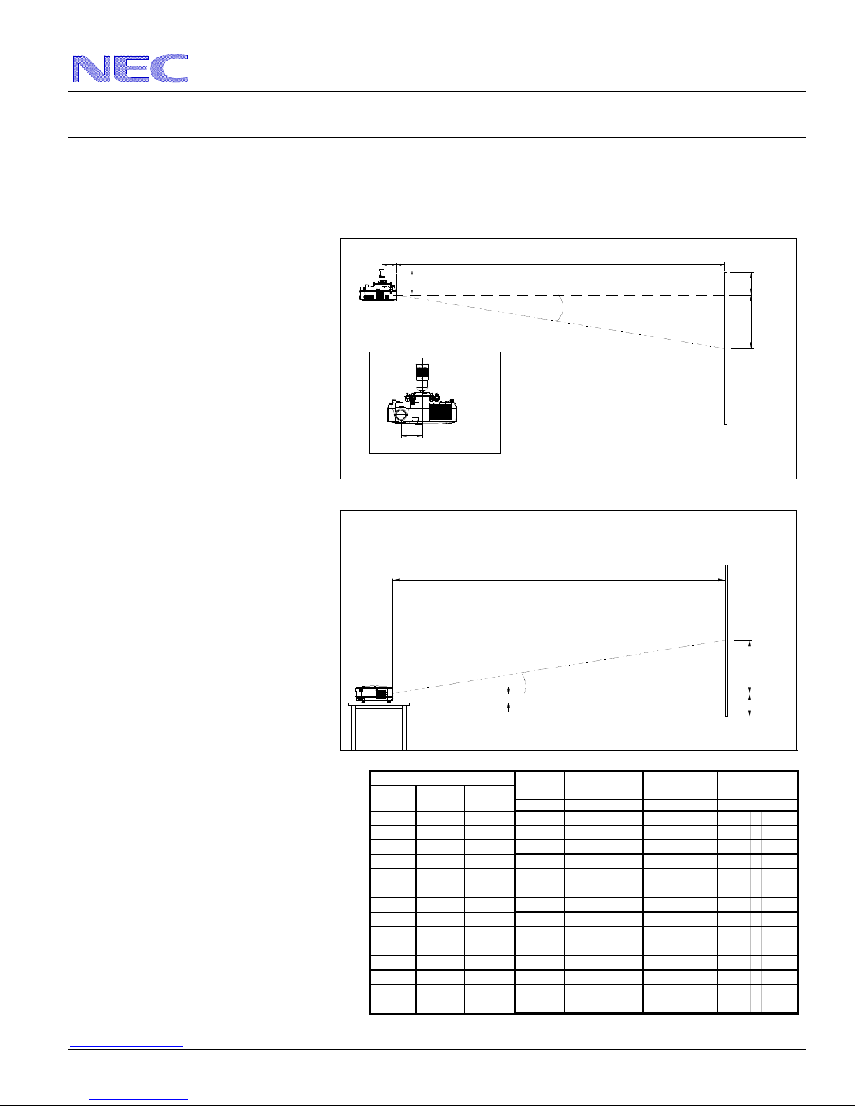
The following shows the proper relative positions of the projector and screen. Refer to the table to determine the position of
installation.
Distances are in inches. For millimeters multiply by 25.4.
Ceiling Mounted
Desktop
Distance Chart for po
pular 4:3 screens
Note: For screen sizes not indicated on the
projection tables, use the formulas on page 1.
www.necdisplay.com NP110/115/215/216 Page 2 of 7
3.84"
9.11"
Lens Offset From
Mount Pipe
3.78"
2.73"
Scr een Siz e ( 4:3)
Diagonal Width(W) Height (H)
inches inches inches inches
30 24 18 12 47 - 52 14.0 - 12.7
60 48 36 23 93 - 104 14.0 - 12.7
67 53.6 40.2 26 104 - 116 14.0 - 12.7
72 57.6 43.2 28 112 - 125 14.0 - 12.7
84 67.2 50.4 33 130 - 145 14.0 - 12.7
90 72 54 35 140 - 156 14.0 - 12.7
100 80 60 39 155 - 173 14.0 - 12.7
120 96 72 47 186 - 208 14.0 - 12.7
150 120 90 59 233 - 260 14.0 - 12.7
180 144 108 70 279 - 312 14.0 - 12.7
210 168 126 82 326 - 364 14.0 - 12.7
240 192 144 94 372 - 416 14.0 - 12.7
270 216 162 106 419 - 468 14.0 - 12.7
300 240 180 117 466 - 520 14.0 - 12.8
C
Throw Distance
C
Throw Distance
B
wide - tele
C
es
Screen Top
Screen Ctr
Screen Ctr
Screen Bottom
D
es
3
5
6
7
8
8
9
11
14
16
19
22
24
27
α
w ide - tele
egrees
D
Lens Ctr
B
B
Lens Ctr
D
NEC Display Solutions of America, Inc.
NP110/115/215/216 Installation Guide
Ceiling Mounted and Desktop Rev 1.0
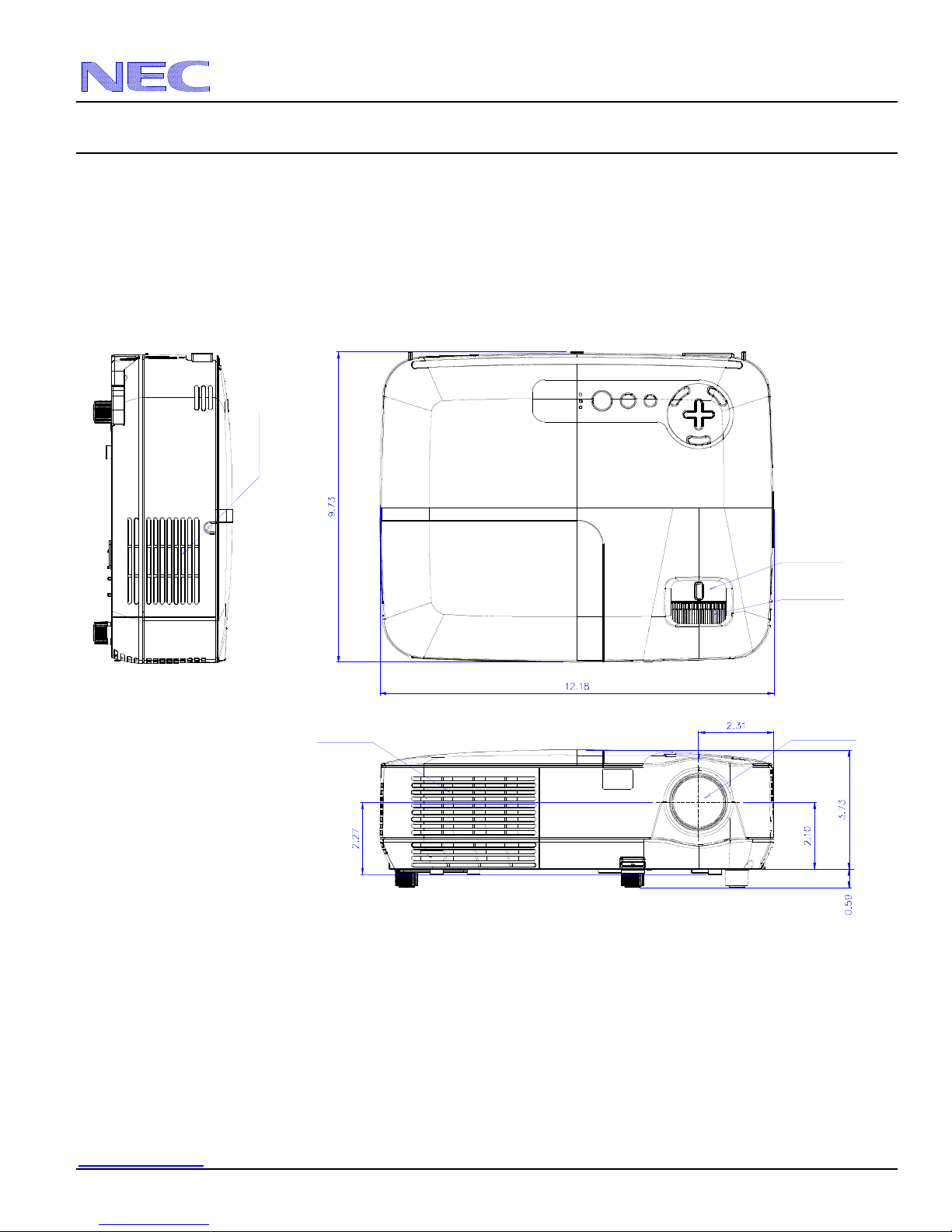
Cabinet Dimensions
The following drawings show the cabinet dimensions.
Dimensions are in inches. For millimeters multiply by 25.4.
Ventilation
Zoom Lever
Focus Lever
Ventilation
Lens Center
www.necdisplay.com NP110/115/215/216 Page 3 of 7
 Loading...