

Page 1

LCD Projector
NP3250/NP2250/NP1250
NP3250W
User’s Manual
Page 2

1st edition, April 2009
Information on USB Wireless LAN:
The NP3250/NP2250/NP1250/NP3250W series projectors distributed in some areas and countries do not come
standard with the USB Wireless LAN Unit.
If you purchase the projector without the USB Wireless LAN Unit installed and need to present to the projector
via a wireless connection, the optional USB Wireless LAN Unit must be installed.
The model without the USB wireless unit has a dummy cover.
• IBM is a trademark or registered trademark of International Business Machines Corporation.
• Macintosh, Mac OS X and PowerBook are trademarks of Apple Inc., registered in the U.S. and other countries.
• Microsoft, Windows, Windows Vista, Internet Explorer, and PowerPoint are either a registered trademark or trademark of Microsoft Corporation in the United States and/or other countries.
• © 2009, ArcSoft, Inc. All rights reserved.
• IDT and HQV are trademarks or registered trademarks of Integrated Device Technology, Inc.
• Trademark PJLink is a trademark applied for trademark rights in Japan, the United States of America and other
countries and areas.
• MicroSaver is a registered trademark of Kensington Computer Products Group, a division of ACCO Brands.
• Other product and company names mentioned in this user’s manual may be the trademarks or registered trademarks of their respective holders.
NOTES
(1) The contents of this guide may not be reprinted in part or whole without permission.
(2) The contents of this guide are subject to change without notice.
(3) Great care has been taken in the preparation of this manual; however, should you notice any questionable
points, errors or omissions, please contact us.
(4) Notwithstanding article (3), NEC will not be responsible for any claims on loss of profit or other matters deemed
to result from using the Projector.
Page 3
Important Information
Safety Cautions
Precautions
Please read this manual carefully before using your NEC NP3250/NP2250/NP1250/NP3250W projector and keep the
manual handy for future reference. Your serial number is located on the bottom of your projector. Record it here:
CAUTION
To turn off main power, be sure to remove the plug from power outlet.
The power outlet socket should be installed as near to the equipment as possible, and should be easily
accessible.
CAUTION
TO PREVENT SHOCK, DO NOT OPEN THE CABINET.
THERE ARE HIGH-VOLTAGE COMPONENTS INSIDE.
REFER SERVICING TO QUALIFIED SERVICE PERSONNEL.
This symbol warns the user that uninsulated voltage within the unit may be sufficient to cause electrical
shock. Therefore, it is dangerous to make any kind of contact with any part inside of the unit.
This symbol alerts the user that important information concerning the operation and maintenance of this
unit has been provided.
The information should be read carefully to avoid problems.
WARNING: TO PREVENT FIRE OR SHOCK, DO NOT EXPOSE THIS UNIT TO RAIN OR MOISTURE.
DO NOT USE THIS UNIT’S PLUG WITH AN EXTENSION CORD OR IN AN OUTLET UNLESS ALL THE
PRONGS CAN BE FULLY INSERTED.
DOC Compliance Notice (for Canada only)
This Class B digital apparatus meets all requirements of the Canadian Interference-Causing Equipment Regulations.
Acoustic Noise Information Ordinance-3. GSGV (for Germany only):
The sound pressure level is less than 70 dB (A) according to ISO 3744 or ISO 7779.
Laser Caution
This label is on the side of the remote control. This mark is on the top of the remote control.
CAUTION
Use of controls or adjustments or performance of procedures other than those specified herein may result in hazardous radiation exposure.
CAUTION
Do not look into the laser pointer while it is on and do not point the laser beam at a person. Serious injury could result.
CAUTION
Avoid displaying stationary images for a prolonged period of time.
Doing so can result in these images being temporarily sustained on the surface of the LCD panel.
If this should happen, continue to use your projector. The static background from previous images will
disappear.
i
Page 4

Important Information
WARNING TO CALIFORNIA RESIDENTS:
Handling the cables supplied with this product will expose you to lead, a chemical known to the State of California to cause birth defects or other reproductive harm. WASH HANDS AFTER HANDLING.
Disposing of your used product
EU-wide legislation as implemented in each Member State requires that used electrical and electronic
products carrying the mark (left) must be disposed of separately from normal household waste. This includes projectors and their electrical accessories or lamps. When you dispose of such products, please
follow the guidance of your local authority and/or ask the shop where you purchased the product.
After collecting the used products, they are reused and recycled in a proper way. This effort will help us
reduce the wastes as well as the negative impact such as mercury contained in a lamp to the human
health and the environment at the minimum level.
The mark on the electrical and electronic products only applies to the current European Union Member
States.
RF Interference (for USA only)
WARNING
The Federal Communications Commission does not allow any modifications or changes to the unit EXCEPT
those specified by NEC Display Solutions of America, Inc. in this manual. Failure to comply with this government
regulation could void your right to operate this equipment. This equipment has been tested and found to comply
with the limits for a Class B digital device, pursuant to Part 15 of the FCC Rules. These limits are designed to
provide reasonable protection against harmful interference in a residential installation. This equipment generates,
uses, and can radiate radio frequency energy and, if not installed and used in accordance with the instructions,
may cause harmful interference to radio communications. However, there is no guarantee that interference will
not occur in a particular installation.
If this equipment does cause harmful interference to radio or television reception, which can be determined by
turning the equipment off and on, the user is encouraged to try to correct the interference by one or more of the
following measures:
• Reorient or relocate the receiving antenna.
• Increase the separation between the equipment and receiver.
• Connect the equipment into an outlet on a circuit different from that to which the receiver is connected.
• Consult the dealer or an experienced radio / TV technician for help.
For UK only: In UK, a BS approved power cable with molded plug has a Black (five Amps) fuse installed for use with
this equipment. If a power cable is not supplied with this equipment please contact your supplier.
Turkish RoHS information relevant for Turkish market
EEE Yönetmeliğine Uygundur.
ii
Page 5
Important Information
10°
Important Safeguards
These safety instructions are to ensure the long life of your projector and to prevent fire and shock. Please read
them carefully and heed all warnings.
Installation
• Do not place the projector in the following conditions:
- on an unstable cart, stand, or table.
- near water, baths or damp rooms.
- in direct sunlight, near heaters or heat radiating appliances.
- in a dusty, smoky or steamy environment.
- on a sheet of paper or cloth, rugs or carpets.
• If you wish to have the projector installed on the ceiling:
- Do not attempt to install the projector yourself.
- The projector must be installed by qualified technicians in order to ensure proper operation and reduce the
risk of bodily injury.
- In addition, the ceiling must be strong enough to support the projector and the installation must be in accordance with any local building codes.
- Please consult your dealer for more information.
WARNING
• Do not cover the lens with the lens cap or equivalent while the projector is on. Doing so can lead to melting of
the cap due to the heat emitted from the light output.
• Do not place any objects, which are easily affected by heat, in front of the projector lens. Doing so could lead
to the object melting from the heat that is emitted from the light output.
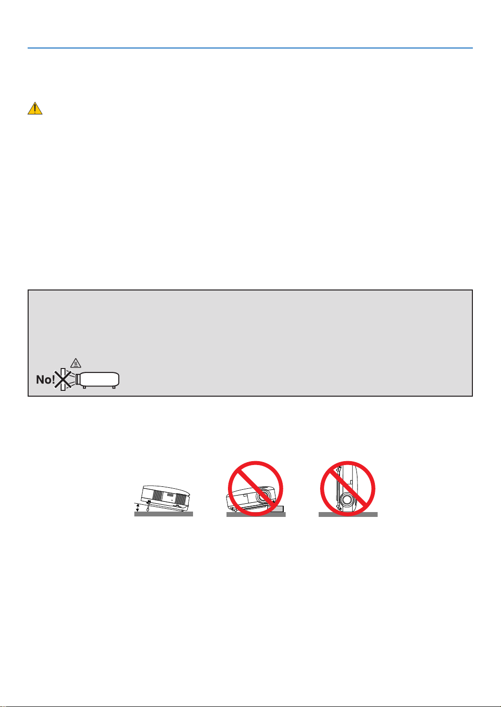
Place the projector in a horizontal position
The tilt angle of the projector should not exceed 10 degrees, nor should the projector be installed in any way other
than the desktop and ceiling mount, otherwise lamp life could decrease dramatically.
iii
Page 6
Important Information
Fire and Shock Precautions
• Ensure that there is sufficient ventilation and that vents are unobstructed to prevent the build-up of heat inside
your projector. Allow at least 4 inches (10cm) of space between your projector and a wall.
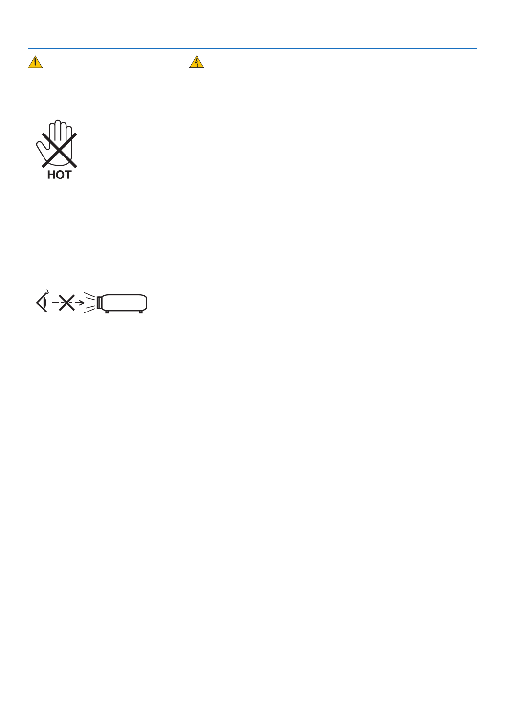
• Do not try to touch the ventilation outlet on the left front (when seen from the front) as it can become heated while
the projector is turned on.
• Prevent foreign objects such as paper clips and bits of paper from falling into your projector. Do not attempt to retrieve any objects that might fall into your projector. Do not insert any metal objects such as a wire or screwdriver
into your projector. If something should fall into your projector, disconnect it immediately and have the object removed by a qualified service personnel.
• Do not place any objects on top of the projector.
• Do not touch the power plug during a thunderstorm. Doing so can cause electrical shock or fire.
• The projector is designed to operate on a power supply of 100-240V AC 50/60 Hz. Ensure that your power supply
fits this requirement before attempting to use your projector.
• Do not look into the lens while the projector is on. Serious damage to your eyes could result.
• Do not place any objects, which are easily affected by heat, in front of a projector exhaust vent.
Doing so could lead to the object melting or getting your hands burned from the heat that is emitted from the ex-
haust.
• Handle the power cable carefully. A damaged or frayed power cable can cause electric shock or fire.
- Do not use any power cables than the supplied one.
- Do not bend or tug the power cable excessively.
- Do not place the power cable under the projector, or any heavy object.
- Do not cover the power cable with other soft materials such as rugs.
- Do not heat the power cable.
- Do not handle the power plug with wet hands.
• Turn off the projector, unplug the power cable and have the projector serviced by a qualified service personnel
under the following conditions:
- When the power cable or plug is damaged or frayed.
- If liquid has been spilled into the projector, or if it has been exposed to rain or water.
- If the projector does not operate normally when you follow the instructions described in this user’s manual.
- If the projector has been dropped or the cabinet has been damaged.
- If the projector exhibits a distinct change in performance, indicating a need for service.
• Disconnect the power cable and any other cables before carrying the projector
• Turn off the projector and unplug the power cable before cleaning the cabinet or replacing the lamp.
• Turn off the projector and unplug the power cable if the projector is not to be used for an extended period of time.
• When using a LAN cable:
For safety, do not connect to the connector for peripheral device wiring that might have excessive voltage.
iv
Page 7
Important Information
CAUTION
•
Always carry your projector by the carrying handle. Before doing so, be sure to lock the carrying handle in place.
To lock the carrying handle, see “To lock the carrying handle” on page 6.
• Do not use the tilt-foot for purposes other than originally intended. Misuses such as using the tilt foot to carry
or hang (from the wall or ceiling) the projector can cause damage to the projector.
• Do not send the projector in a soft case by parcel delivery service or cargo shipment. The projector inside the
soft case could be damaged.
• Select [HIGH] in Fan mode if you continue to use the projector for consecutive days. (From the menu, select
[SETUP] → [OPTIONS] → [FAN MODE] → [HIGH].)
• Before using Direct Power Off, be sure to allow at least 20 minutes immediately after turning on the projector
and starting to display an image.
• Do not unplug the power cable from the wall outlet or projector when the projector is powered on. Doing so can
cause damage to the AC IN connector of the projector and (or) the prong plug of the power cable.
To turn off the AC power supply when the projector is powered on, use a power strip equipped with a switch
and a breaker.
• Do not try to touch the ventilation outlet on the left front (when seen from the front) as it can become heated
while the projector is turned on and immediately after the projector is turned off.
• Do not turn off the AC power for 60 seconds after the lamp is turned on and while the POWER indicator is
blinking green. Doing so could cause premature lamp failure.
Caution on Handling the Optional Lens
When shipping the projector with the optional lens, remove the optional lens before shipping the projector. The lens
and the lens shift mechanism may encounter damage caused by improper handling during transportation.
Do not hold the lens part when carrying the projector.
Doing so could cause the focus ring to rotate, resulting in accidental dropping of the projector.
Remote Control Precautions
• Handle the remote control carefully.
• If the remote control gets wet, wipe it dry immediately.
• Avoid excessive heat and humidity.
• Do not heat, take apart, or throw batteries into fire.
• If you will not be using the remote control for a long time, remove the batteries.
• Ensure that you have the batteries’ polarity (+/−) aligned correctly.
• Do not use new and old batteries together, or use different types of batteries together.
• Dispose of used batteries according to your local regulations.
Note for US Residents
The lamp in this product contains mercury. Prease dispose according to Local, State or Federal Laws.
Lamp Replacement
• To replace the lamp, follow all instructions provided on page 136.
• Be sure to replace the lamp when the message [THE LAMP HAS REACHED THE END OF ITS USABLE LIFE.
PLEASE REPLACE THE LAMP.] appears. If you continue to use the lamp after the lamp has reached the end
of its usable life, the lamp bulb may shatter, and pieces of glass may be scattered in the lamp case. Do not touch
them as the pieces of glass may cause injury.
If this happens, contact your dealer for lamp replacement.
A Lamp Characteristic
The projector has a high-pressure mercury lamp as a light source.
A lamp has a characteristic that its brightness gradually decreases with age. Also repeatedly turning the lamp on
and off will increase the possibility of its lower brightness.
CAUTION:
When removing the lamp from a ceiling-mounted projector, make sure that no one is under the projector. Glass
fragments could fall if the lamp has been burned out.
v
Page 8

Important Information
About High Altitude mode
• Set [FAN MODE] to [HIGH ALTITUDE] when using the projector at altitudes approximately 5500 feet/1600 meters or higher.
Using the projector at altitudes approximately 5500 feet/1600 meters or higher without setting to [HIGH ALTI-
TUDE] can cause the projector to overheat and the protector could shut down. If this happens, wait a couple
minutes and turn on the projector.
• Using the projector at altitudes less than approximately 5500 feet/1600 meters and setting to [HIGH ALTITUDE]
can cause the lamp to overcool, causing the image to flicker. Switch [FAN MODE] to [AUTO].
• Using the projector at altitudes approximately 5500 feet/1600 meters or higher can shorten the life of optical
components such as the lamp.
About Copyright of original projected pictures:
Please note that using this projector for the purpose of commercial gain or the attraction of public attention in a venue such as a coffee shop or hotel and employing compression or expansion of the screen image with the following
functions may raise concern about the infringement of copyrights which are protected by copyright law.
[ASPECT RATIO], [KEYSTONE], Magnifying feature and other similar features.
USB Wireless LAN Unit
Cautions on Usage
Warning
• The USB Wireless LAN Unit is not meant for use with facilities or equipment involving the safeguard of human life, such as medical equipment, nuclear facilities or equipment, aeronautical or space equipment, transportation facilities or equipment, etc., or with facilities or equipment requiring high levels of reliability. Do not
use the USB Wireless LAN Unit in such cases.
• Do not use the USB Wireless LAN Unit near cardiac pacemakers.
• Do not use the USB Wireless LAN Unit near medical equipment. Doing so may cause electromagnetic interference with the medical equipment, possible leading to death.
• Do not disassemble or modify the USB Wireless LAN Unit in any way. Doing so could lead to fire or electric
shock.
• Do not use the USB Wireless LAN Unit in wet or moist places, such as in bathrooms or near humidifiers. Doing so could lead to fire, electric shock or malfunction.
Caution
To prevent damage due to static electricity, eliminate any static electricity from your body before touching the
USB Wireless LAN Unit.
• Static electricity from the human body may damage the USB Wireless LAN Unit. Before touching the USB
Wireless LAN Unit, touch an aluminum sash, a door knob, or some other metal object around you to eliminate the static electricity.
Caution
The radio waves used by the USB Wireless LAN Unit pass through the wood or glass used in normal homes (but
not through window panes with built-in metallic mesh).
The radio waves do not pass through iron reinforcing bars, metal or concrete, however, so the USB Wireless LAN
Unit cannot be used for communicating through walls or floors made with these materials.
vi
Page 9

Important Information
FCC Compliance
This device complies with Part 15 of the FCC Rules. Operation is subject to the following two conditions:(1) this
device may not cause harmful interference and (2) this device must accept any interference received, including
interference that may cause undesired operation.
This equipment has been tested and found to comply with the limits for a Class B Personal Computer and Peripheral, pursuant to Part 15 of the FCC Rules. These limits are designed to provide reasonable protection against harmful interference in a residential installation.
This equipment generates, uses and can radiate radio frequency energy and, if not installed and used in accordance with the instructions, may cause harmful interference to radio communications.
However, there is no guarantee that interference will not occur in a particular installation. If this equipment does
cause harmful interference to radio or television reception, which can be determined by turning the equipment off
and on, the user is encouraged to try to correct the interference by one or more of the following measures:
• Reorient or relocate the receiving antenna.
• Increase the separation between the equipment and receiver.
• Connect the equipment into an outlet on a circuit different from that to which the receiver is connected.
• Consult the dealer or an experienced radio/TV technician for help.
This equipment has been tested to comply with the limits for a Class B personal computer and peripheral, pursuant to Subpart B of Part 15 of FCC Rules. Only peripherals (computer input/output devices, terminals, printers, etc.)
certified (DoC) or verified to comply with Class B limits may be attached to this equipment. Operation with noncertified (DoC) or non-verified personal computer and/or peripherals is likely to result in Interference to radio and TV
reception.
The connection of a unshielded equipment interface cable to this equipment will invalidate the FCC Certification of
this device and may cause interference levels which Exceed the limits established by FCC for equipment.
You are cautioned that changes or modifications not expressly approved by the party responsible for compliance
could void your authority to operate the equipment.
Regulatory Information/Disclaimers
Installation and use of this Wireless LAN device must be in strict accordance with the instructions included in the
user documentation provided with the product. Any changes or modifications (including the antennas) made to this
device that are not expressly approved by the manufacturer may void the user’s authority to operate the equipment.
The manufacturer is not responsible for any radio or television interference caused by unauthorized modification of
this device, or the substitution of the connecting cables and equipment other than manufacturer specified. It is the
responsibility of the user to correct any interference caused by such unauthorized modification, substitution or attachment. Manufacturer and its authorized resellers or distributors will assume no liability for any damage or violation of government regulations arising from failing to comply with these guidelines.
CAUTION
To comply with FCC RF exposure compliance requirements, the antenna used for this transmitter must be installed to provide a separation distance of at least 7.87"/20cm from all persons and must not be co-located or
operating in conjunction with any other antenna or transmitter.
SAR compliance has been established in typical laptop computer(s) with USB slot, and product could be used in
typical laptop computer with USB slot. Other application like handheld PC or similar device has not been verified
and may not compliance with related RF exposure rule and such use shall be prohibited.
vii
Page 10

Important Information
Usage restrictions in North America
The following channels can be used indoors only.
• In the United States and Canada: 36, 40, 44, and 48 channels
• In Mexico: 149, 153, 157, 161, and 165 channels
The other channels can be used both indoors and outdoors.
This Class B digital apparatus complies with Canadian RSS-210.
Cet appareil numerique de la Classe B est conforme a la norme CNR-210 du Canada.
To comply with Canada RSS-210(Issue 7) section A9.4(b)(ii); this radio product will not transmit on any channels
operating in the exclusion band of 5600 - 5650MHz. All channels in the 5600 - 5650MHz band will be disabled by
factory firmware and is not user changeable.
Regulatory Statement:
Operation of this device is subjected to the following National regulations and may be prohibited to use if certain restriction should be applied.
France:
Outdoor use limited to 10mW e.i.r.p. within the band 2454 – 2483.5 MHz. Derogation in French overseas departments of Guyane and La Reunion: outdoor use not allowed in band 2400 - 2420 MHz.
Hereby, NEC Display Solutions, Ltd. declares that this USB Wireless LAN Unit (Model: NP01LM) is in compliance
with the essential requirements and other relevant provisions of Directive 1999/5/EC.
Cautions on security when using wireless LAN products
With a wireless LAN, radio waves are used instead of LAN cables for the exchange of data between the wireless
access points (computers, etc.), offering the advantage that LAN connections can be made freely within the range
of the radio waves.
On the other hand, the radio waves reach all points within this range, regardless of walls or other obstacles, possibly resulting in the problems described below if the proper security measures are not taken.
• Contents of transmissions may be intercepted
Malicious third parties may purposely intercept the radio waves and steal information contained in the transmissions, including such personal information as ID numbers, passwords, credit card numbers, e-mail messages,
etc.
• Improper intrusions
Malicious third parties may without permission access the personal or company network and steal personal or
confidential information, pretend to be someone else and leak incorrect information, rewrite information that has
been intercepted, introduce computer viruses or otherwise damage data or the system, etc.
Wireless LAN cards and wireless access points generally include security measures for dealing with these problems. Making the proper security settings before using the products can reduce the risk of such problems arising.
We recommend that you fully understand the problems that can arise when using the products without making the
security settings, then that you make the security settings based on your own decision and at your own discretion.
Operation of the USB Wireless LAN Unit is subjected to the regulations of the countries listed below, and may be
prohibited to use outside the country where you purchased. If you need to use the projector outside the country
where you purchased, you must remove the USB Wireless LAN Unit from the projector before exporting.
viii
Page 11

Table of Contents
Important Information
1. Introduction
What’s in the Box? ......................................................................................................... 1
Introduction to the Projector ..........................................................................................2
Congratulations on Your Purchase of the Projector ................................................. 2
Features you’ll enjoy : .............................................................................................. 2
About this user’s manual ..........................................................................................3
Part Names of the Projector .......................................................................................... 4
Front/Top .................................................................................................................. 4
Rear ......................................................................................................................... 4
Bottom...................................................................................................................... 5
Carrying the Projector
Top Features ............................................................................................................ 7
Terminal Panel Features .......................................................................................... 8
Part Names of the Remote Control ...............................................................................9
Battery Installation .................................................................................................10
Operating Range for Wireless Remote Control
Remote Control Precautions .................................................................................. 11
Using the Remote Control in Wired Operation .......................................................11
.......................................................................................................... 1
2. Installation and Connections
Setting Up the Screen and the Projector ..................................................................... 12
Selecting a Location [NP3250/NP2250/NP1250]................................................... 12
Selecting a Location [NP3250W] ........................................................................... 13
Making Connections .................................................................................................... 14
Connecting Your PC or Macintosh Computer ......................................................... 14
Connecting an External Monitor ............................................................................ 16
Connecting Your DVD Player with Component Output ........................................... 17
Connecting Your VCR............................................................................................. 18
Connecting to a Network........................................................................................ 19
Connecting the Supplied Power Cable .................................................................. 22
............................................................................................i
.............................................................................................. 5
...................................................... 10
................................................................... 12
3. Projecting an Image (Basic Operation)
Turning on the Projector .............................................................................................. 23
Note on Startup screen (Menu Language Select screen) ...................................... 24
Selecting a Source ......................................................................................................25
Selecting the computer or video source................................................................. 25
Adjusting the Picture Size and Position ....................................................................... 26
Adjusting the position of a projected image ........................................................... 27
Adjusting the focus (Focus ring) ............................................................................28
Finely adjusting the size of an image (Zoom lever) ................................................ 28
Adjusting the Tilt Foot ............................................................................................ 29
Correcting Keystone Distortion .................................................................................... 30
Optimizing an RGB Image Automatically ....................................................................32
Adjusting the Image Using Auto Adjust .................................................................. 32
Adjusting Volume Up & Down ...................................................................................... 32
Using the Laser Pointer ............................................................................................... 33
Setting the function switch ..................................................................................... 33
..............................................23
ix
Page 12

Table of Contents
Turning off the Projector .............................................................................................. 34
After Use...................................................................................................................... 34
4. Convenient Features
Turning Off the Image and Sound ................................................................................ 35
Freezing a Picture .......................................................................................................35
Enlarging and Moving a Picture ................................................................................... 35
Changing Lamp Mode ................................................................................................. 36
Getting Integrated Help ...............................................................................................36
Using a USB Mouse .................................................................................................... 37
Operate the Menus using the USB mouse ............................................................37
Using the Optional Remote Mouse Receiver (NP01MR) ............................................38
Correcting Horizontal and Vertical Keystone Distortion [CORNERSTONE] ....................40
Cornerstone ........................................................................................................... 40
Displaying Two Pictures at the Same Time .................................................................. 43
9
Selecting the PIP or SIDE BY SIDE Mode [MODE] ............................................... 43
[POSITION] ............................................................................................................ 44
Preventing Unauthorized Use of the Projector ............................................................ 45
Turning on the Security function by assigning a keyword for the first time ............. 45
Checking If Security is enabled .............................................................................. 48
Disabling the Security ............................................................................................ 49
Limiting Access Level to Available Menu Items ........................................................... 50
Operation Using an HTTP Browser ............................................................................. 53
L
Overview ................................................................................................................ 53
Preparation Before Use .........................................................................................53
Handling of the Address for Operation via a Browser ............................................ 53
Structure of the HTTP Server ................................................................................54
Projecting Your Computer’s Screen Image from the Projector via a Network
M
[NETWORK PROJECTOR] .................................................................................... 56
Using the Projector to Operate Your Computer via a Network [REMOTE DESKTOP] 60
N
..................................................................................... 35
5. Using the Viewer
Making the Most out of the Viewer Function ................................................................ 65
Features ................................................................................................................. 65
File restrictions during Viewer playback ................................................................. 65
Saving data to a USB memory device ......................................................................... 66
Using ArcSoft MediaImpression............................................................................. 66
Using Windows Explorer to save files .................................................................... 66
Operating the Viewer Function from the Projector (playback) ..................................... 67
Projecting slides (Viewer) ......................................................................................67
Operating Viewer Menu ......................................................................................... 67
Projecting a movie file ............................................................................................ 68
Setting Option for Viewer ....................................................................................... 70
THUMBNAILS menu .............................................................................................. 71
Exiting Viewer ........................................................................................................ 71
Changing Background Logo ........................................................................................ 72
Projecting data from shared folder (Viewer) ................................................................ 73
Connecting the projector to the shared folder ....................................................... 73
Reflecting changes of the shared folder on the thumbnail screen. ........................ 75
.............................................................................................65
x
Page 13

Table of Contents
Disconnecting the shared folder from the projector ............................................... 76
Projecting data from media server (Viewer) ................................................................ 77
Setting up “Media Sharing” in Windows Media Player 11 ...................................... 77
Connecting the projector to the media server ........................................................ 79
6. Using On-Screen Menu
Using the Menus .......................................................................................................... 80
Using ADVANCED menu and BASIC menu ........................................................... 81
Entering alphanumeric characters by using Software Keyboard ........................... 81
Menu tree ....................................................................................................................82
Menu Elements ............................................................................................................ 84
Menu Descriptions & Functions [SOURCE] ................................................................85
COMPUTER 1 and 2 .............................................................................................85
COMPUTER 3 (RGB Digital) ................................................................................. 85
COMPONENT........................................................................................................ 85
VIDEO .................................................................................................................... 85
S-VIDEO ................................................................................................................ 85
VIEWER ................................................................................................................. 85
NETWORK ............................................................................................................. 85
ENTRY LIST .......................................................................................................... 85
Menu Descriptions & Functions [ADJUST] .................................................................. 88
[PICTURE] ............................................................................................................. 88
[IMAGE OPTIONS] ................................................................................................ 91
[VIDEO] .................................................................................................................. 96
[AUDIO] .................................................................................................................. 97
Menu Descriptions & Functions [SETUP] .................................................................... 98
[BASIC] .................................................................................................................. 98
[MENU] ................................................................................................................106
[INSTALLATION(1)] .............................................................................................. 107
[INSTALLATION(2)] .............................................................................................. 110
[OPTIONS] ........................................................................................................... 126
Menu Descriptions & Functions [INFO.] .................................................................... 129
[USAGE TIME] ..................................................................................................... 129
[SOURCE (1)] ...................................................................................................... 130
[SOURCE (2)] ...................................................................................................... 130
[WIRED LAN] ....................................................................................................... 131
[WIRELESS LAN (1)] ........................................................................................... 131
[WIRELESS LAN (2)] ........................................................................................... 132
[VERSION (1)] .....................................................................................................132
[VERSION (2)] .....................................................................................................132
Menu Descriptions & Functions [RESET] .................................................................. 133
Returning to Factory Default ................................................................................ 133
................................................................................ 80
7. Maintenance
Cleaning or Replacing the Filter ................................................................................ 134
Cleaning the Cabinet and the Lens ........................................................................... 135
Replacing the Lamp................................................................................................... 136
8. Using Optional Lenses
Table of Throw Distances and Screen Sizes for Optional Lenses .................................... 139
.................................................................................................... 134
............................................................................... 139
xi
Page 14

Table of Contents
Lens Shift Adjustable Range ..................................................................................... 141
Replacing with Optional Lens .................................................................................... 142
9. Appendix
Troubleshooting ......................................................................................................... 144
Indicator Messages .............................................................................................. 144
Specifications ............................................................................................................147
Cabinet Dimensions ..................................................................................................151
Screen Size and Projection Distance ........................................................................ 152
[NP3250/NP2250/NP1250] .................................................................................. 152
[NP3250W]........................................................................................................... 153
Pin Assignments of D-Sub COMPUTER 1 Input Connector .....................................156
Mini D-Sub 15 Pin Connector ..............................................................................156
Compatible Input Signal List ...................................................................................... 157
PC Control Codes and Cable Connection ................................................................. 158
PC Control Codes ................................................................................................ 158
Cable Connection ................................................................................................159
PC Control Connector (D-SUB 9P) ...................................................................... 159
Removing and Attaching the USB Wireless LAN Unit ............................................... 160
Troubleshooting Check List ........................................................................................ 163
9
TravelCare Guide ....................................................................................................... 165
............................................................................................................. 144
xii
Page 15
1. Introduction
OFF
VIDEO
S-VIDEO
VIEWER
NETWORK
COMPUTER
COM
PONENT
ON
POWER
POWER
LASER
3D REFORM
AUTO ADJ.
ASPECT
HELP
PICTURE
PIC-MUTE
LAMP MODE
R-CLICK
L-CLICK
MOUSE
FREEZE
PIP
VOLUME
MAGNIFY
PAGE
SELECT
3
1
2
UP
DOWN
USB
LAMP
STATUS
POWER
SOURCE
AUTO ADJUS
T
3D REFORM
ON/STAND BY
S
ELE
CT
Y
L
E
FT
R
IG
H
T
DOWN
UP
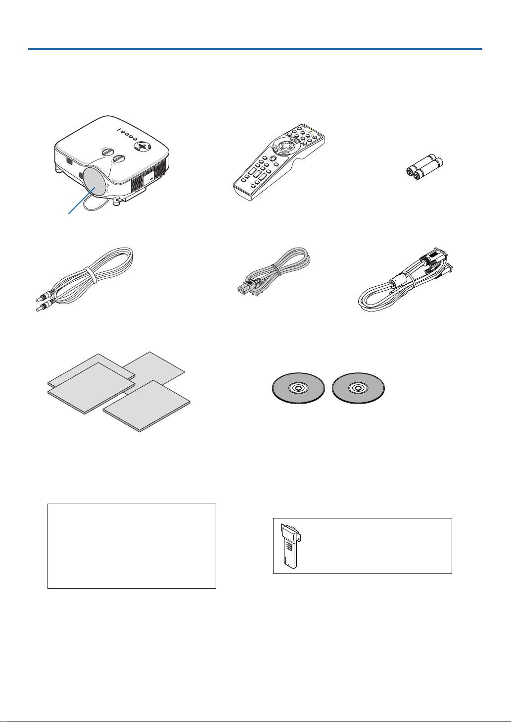
What’s in the Box?
Make sure your box contains everything listed. If any pieces are missing, contact your dealer.
Please save the original box and packing materials if you ever need to ship your Projector.
Projector
Lens cap
(24FT9741)
Remote Cable
(7N520019)
• Important Infomation (For North America:
7N8P9481) (For Other countries than North
America: 7N8P9481 and 7N8P9491)
• Quick Setup Guide (7N8P9471)
• Wired and Wireless Network Setup Guide
(7N8P9501)
For North America only
Registration card
Limited warranty
For customers in Europe:
You will find our current valid Guarantee
Policy on our Web Site:
www.nec-display-solutions.com
Remote control
(7N900801)
Power cable
(For North America:
7N080204)
(For Europe and other
countries: 7N080011)
CD-ROM
User’s manual (7N951321) and
User Supportware 6 (7N951311)
• Security sticker
(24L67991)
• Anti-theft screw for lens × 1
(24V00841)
Installed USB wireless LAN unit
North America: NP01LM3
Europe: NP01LM2
Joint module
Batteries (AA × 2)
VGA signal cable
(7N520052)
1
Page 16

1. Introduction
Introduction to the Projector
This section introduces you to the NP3250/NP2250/NP1250/NP3250W projector and describes key features and
controls.
Congratulations on Your Purchase of the Projector
The NP3250/NP2250/NP1250 is a sophisticated XGA projector that produces an enhanced display. NP3250W is a
WXGA projector. With the NP3250/NP2250/NP1250/NP3250W you will be able to project images up to 500" (measured diagonally). Enjoy crisp and sharp large screen display from your PC, workstation or Macintosh computer,
DVD player, VCR, satellite hookup, HDTV source, as well as images from your USB storage device. The NP3250/
NP2250/NP1250/NP3250W provides for enhanced security options to help deter projector theft and provides for full
projector control through the PC control port (D-Sub 9 Pin) and LAN support. With input and output flexibility, long
lamp life and a full function remote, the NP3250/NP2250/NP1250/NP3250W lets you enjoy larger than life viewing
from a compact and easy to setup and use projector.
Features you’ll enjoy :
• LCD projector with high resolution and high brightness
High resolution display - up to UXGA compatible, XGA native resolution.
• WXGA 1280 × 800 native resolution (NP3250W only)
The NP3250W with WXGA (1280 × 800) native resolution was designed with the future in mind by supporting
emerging wide screen resolutions being used in more of today’s computers and SD signals along with the ever
increasing demands for HD signals.
• Extensive optional lens
One standard lens and five types of optional lenses are available
• Lens shift mechanism offers installation flexibility
Manual lens shift that can be adjusted by turning dials on the top of the projector
• Direct Power Off
The projector has a feature called “Direct Power Off”. This feature allows the projector to be turned off (even
when projecting an image) by using the Main Power Switch or disconnecting the AC power supply.
To turn off the AC power supply when the projector is powered on, use a power strip equipped with a switch and
a breaker.
NOTE: Before using Direct Power Off, be sure to allow at least 20 minutes immediately after turning on the projector and
starting to display an image.
• Auto Power On, and Auto Power Off functions
The AUTO POWER ON(AC), AUTO POWER ON(COMP1/2), AUTO POWER OFF, and OFF TIMER features
eliminate the need to always use the POWER button on the remote control or projector cabinet.
• Integrated RJ-45 connector for wired networking capability along with wireless networking capabilities
An RJ-45 connector and a USB Wireless LAN unit are equipped as standard features*.
Present from anywhere in the room when using as a wireless LAN projector and software contained on the sup-
plied User Supportware 6 CD-ROM, no physical signal cable connection to a PC is required.
NOTE: The NP3250/NP2250/NP1250/NP3250W series projectors distributed in some areas and countries do not come standard with the USB Wireless LAN Unit.
If you purchase the projector without the USB Wireless LAN Unit installed and need to present to the projector via a wireless
connection, the optional USB Wireless LAN Unit must be installed.
• Windows Vista standard functions Network Projector and Remote Desktop can be used
A Windows Vista-based computer can be operated using the projector over a network.
The projector supports the Network Projector function and the Remote Desktop function of Windows Vista.
2
Page 17

1. Introduction
• A variety of input ports and a comprehensive array of system control interfaces
This projector supports input signals on the following ports: BNC, DVI-D, 15pin D-Sub, component, composite
and S-video.
• Wall Color Correction
Built-in Wall Color Correction presets provide for adaptive color correction when projecting onto non-white
screen material (or a wall).
• IDT HQV technology produces superior video processing
The technology produces superior video processing using pixel-based, motion-adaptive de-interlacing to remove
undesirable motion artifacts typical of interlaced signals.
• Seven picture preset modes for user adjustable picture and color settings
Each picture preset mode can be customized and memorized according to your preference.
• Preventing unauthorized use of the projector
Enhanced smart security settings for password protection, cabinet control panel lock, and USB memory protec-
tion key to help prevent unauthorized access, adjustments and theft deterrence.
• The optional remote control (NP02RC) allows you to assign a CONTROL ID to the projector
Multiple projectors can be operated separately and independently with the same single remote control by as-
signing an ID number to each projector.
• Viewer function supports LAN
Image or movie files stored in a shared folder or on a media server can be projected using the Viewer function
via the LAN.
The Viewer supports the “media sharing” function in Windows Media Player 11.
About this user’s manual
The fastest way to get started is to take your time and do everything right the first time. Take a few minutes now to
review the user’s manual. This may save you time later on. At the beginning of each section of the manual you’ll find
an overview. If the section doesn’t apply, you can skip it.
3
Page 18
LAMP
STATUS
POW
ER
ON
/
STAN
D BY
SOURCE
AUTO ADJUST
3D REFORM
SELECT
US
B
L
E
N
S
S
H
IF
T
L
E
F
T
RIGH
T
DOWN
UP
WIRELESS
WIRELESS
USB
LAMP
STATUS
POWER
SOURCE
AUTO ADJUST
3D REFORM
ON/STAND BY
SELECT
LENS SHIFT
LEFT
RIGHT
DOWN
UP
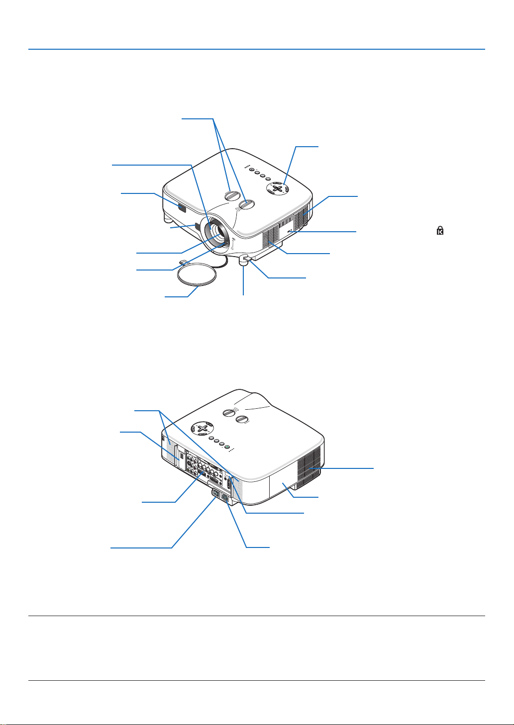
Part Names of the Projector
Front/Top
1. Introduction
Lens Shift Dial (Right / Left, Up / Down)
(→ page 27)
Controls
(→ page 7)
Focus Ring
(→ page 28)
Remote Sensor
(→ page 10)
LENS RELEASE Button
(→ page 142)
Lens
Zoom Lever
(→ page 28)
Adjustable Tilt Foot Lever
Ventilation (inlet) / Filter
(→ page 134)
Built-in Security Slot ( )*
Ventilation (inlet) / Filter
(→ page 134)
(→ page 29)
Lens Cap
Adjustable Tilt Foot
(→ page 29)
* This security slot supports the MicroSaver® Security System. MicroSaver® is a registered trademark of Kens-
ington Microware Inc. The logo is trademarked and owned by Kensington Microware Inc.
Rear
Stereo Speaker (5W × 2)
USB Wireless LAN unit
The model without the USB
wireless LAN unit has a dummy
cover here.
Ventilation (outlet)
Heated air is exhausted from
here.
Terminal Panel
(→ page 8)
Lamp Cover
(→ page 136)
Remote Sensor
(→ page 10)
Main Power Switch
When you plug the supplied power cable into an active
wall outlet and turn on the Main Power switch, the POWER indicator turns orange and the projector is in standby
AC Input
Connect the supplied power cable’s three-pin plug here,
and plug the other end into an active wall outlet.
(→ page 22)
mode.
(→ page 23)
NOTE:
The USB Wireless LAN Unit emits weak radio waves when the projector is in standby mode or turned on.
If you use the projector with the USB Wireless LAN Unit in the area where the use of wireless LAN equipment is prohibited, disable the wireless function. (
* To stop emitting radio waves from the USB Wireless LAN Unit, select [NETWORK SETTINGS] → [WIRELESS] → [PROFILES]
→
[DISABLE].
→
page 114)
4
Page 19
1. Introduction
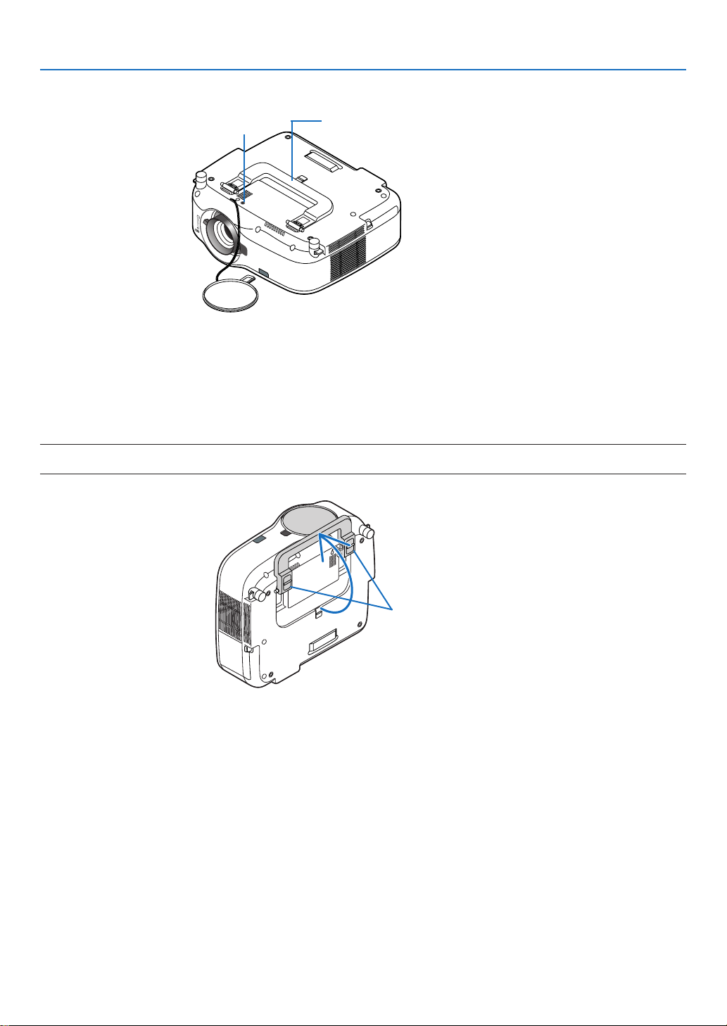
Bottom
Anti-theft Screw for Lens
(→ page 143)
Carrying Handle
Carrying the Projector
Always carry your projector by the handle.
Ensure that the power cable and any other cables connecting to video sources are disconnected before moving the
projector.
When moving the projector or when it is not in use, cover the lens with the lens cap.
NOTE: To stand the projector on its end, do so by holding the cabinet, not by holding the carrying handle.
Doing so can cause damage to the carrying handle.
Lock
5
Page 20
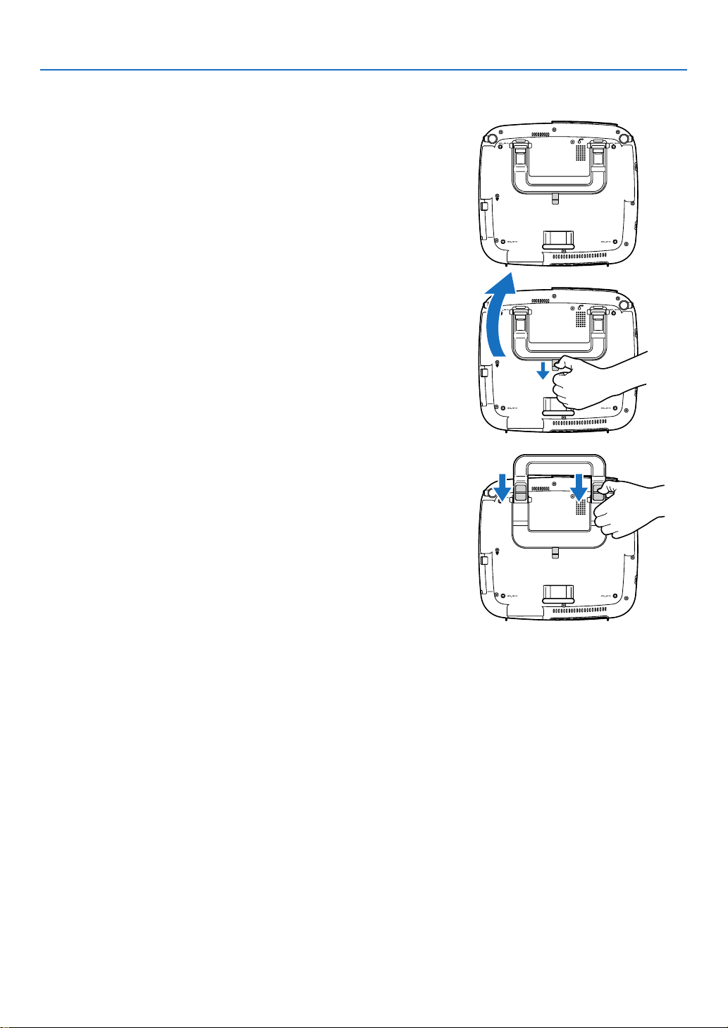
To lock the carrying handle
1. Carefully place the projector on its end.
2. Pull up the carrying handle with the catch pressed down.
3. Press down the left and right locks to set the carrying handle
in place.
• To place back the carrying handle, press up the left and right
locks and pull down the carrying handle.
1. Introduction
6
Page 21
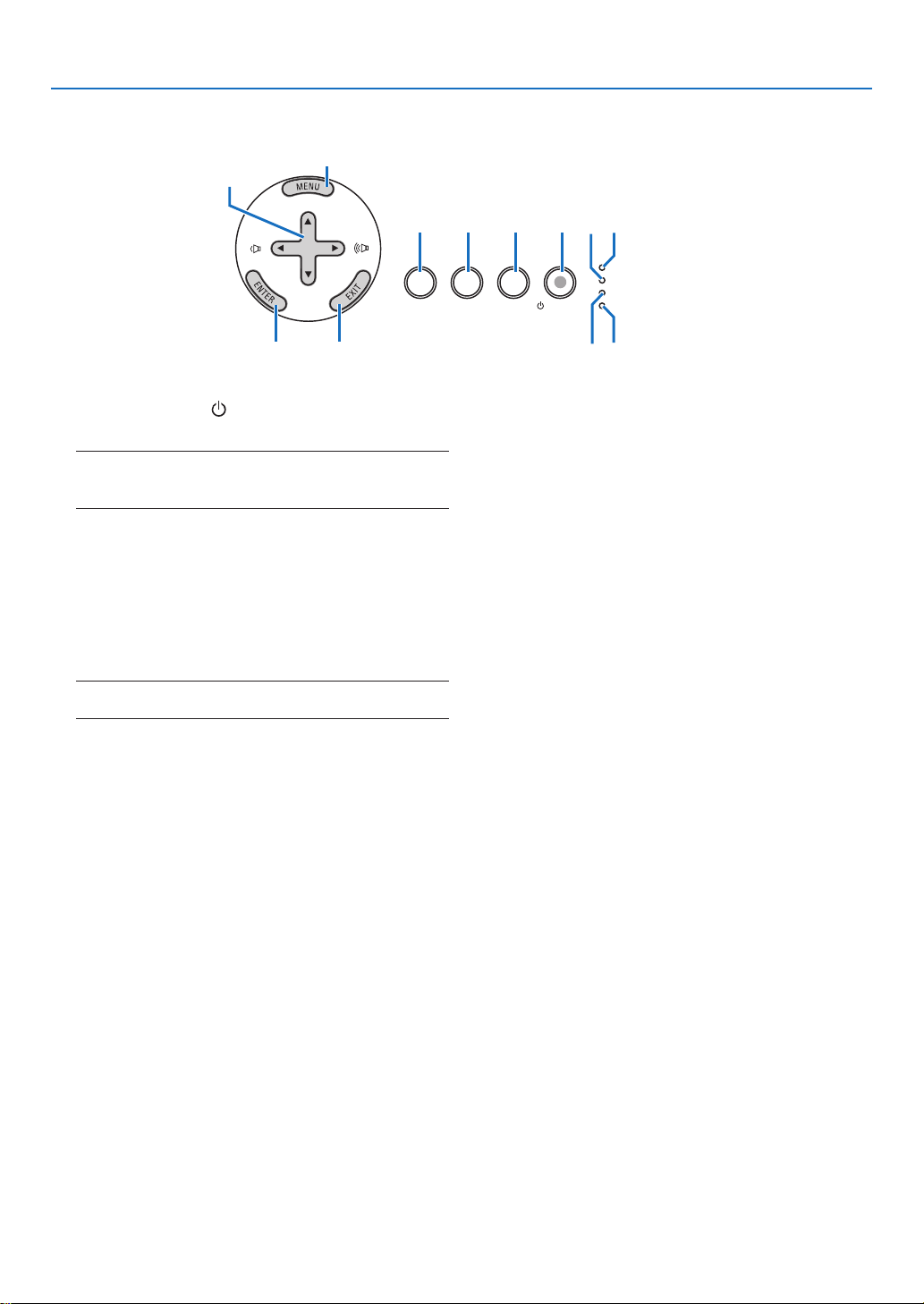
Top Features
SELECT
USB
LAMP
STATUS
POWER
ON/STAND BY
SOURCE
AUTO ADJUST
3D REFORM
12
1 4 5
23
678
11
10
9
1. Introduction
1. POWER Button ( ) (ON / STAND BY) (→ page
23, 34)
NOTE: To turn on the projector, press and hold this button
for a minimum of two seconds. To turn off the projector,
press this button twice.
2. POWER Indicator (→ page 23, 34, 144)
3. STATUS Indicator (
4. LAMP Indicator (
→
→
page
page
136, 144)
144)
5. USB Indicator
Lights when a USB memory is inserted into the USB
port.
NOTE: The USB indicator will not light when non-USB storage devices such as USB mouse devices are inserted.
6. SOURCE Button
7. AUTO ADJUST Button (
8. 3D REFORM Button (
→
9. MENU Button
10. SELECT
/ Volume Buttons
11. ENTER Button
12. EXIT Button
→
page 3
2)
page 30, 40)
7
Page 22
1. Introduction
WIRELESS
USB(LAN)
WIRELESS
14
7 8 1011
134 12 3 2
165 9
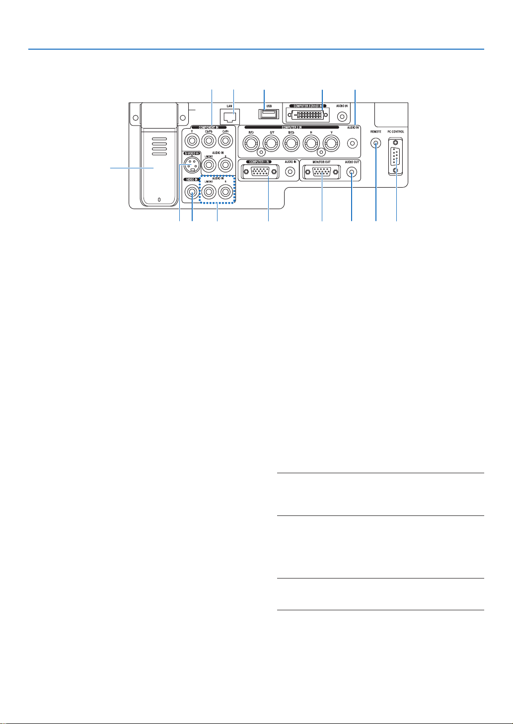
Terminal Panel Features
The actual appearance of the terminal panel may differ slightly from that shown in the drawing, but this does not affect the projector’s performance.
1. COMPUTER 1 IN/Component Connector (Mini
16)
→
14, 16)
page
→
→
→
page
→
page
page
17)
page
14, 15, 17)
14)
→
18)
→
page
16)
page
D-Sub 15 Pin) (
AUDIO IN (Stereo Mini Jack) (
2. COMPUTER 2 IN/Component (R/Cr, G/Y, B/Cb, H,
V) Connectors (BNC × 5) (→page 14)
AUDIO IN (Stereo Mini Jack) (
3. COMPUTER 3 (DVI-D) IN Connector (24 Pin)
(HDCP compatible) (→page 15)
AUDIO IN (Stereo Mini Jack) (→page 15)
4. COMPONENT IN (Y, Cb/Pb, Cr/Pr) Connectors
(RCA) (→page 17)
AUDIO L/MONO, R (RCA) (
5. S-VIDEO IN Connector (Mini DIN 4 Pin) (
18)
6. VIDEO IN Connector (RCA) (
7.
VIDEO/S-VIDEO AUDIO L/MONO, R (RCA) (→page
18)
8. MONITOR OUT Connector (Mini D-Sub 15 Pin)
(→page
9. AUDIO OUT (Stereo Mini Jack) (
10.
PC CONTROL Port (D-Sub 9 Pin) (→page 158, 159)
Use this port to connect your PC or control system
to control your projector via a serial cable. This
enables you to control the projector using serial
communication protocol. A commercially available
RS232C cross cable is required to use this port. You
can also control the projector by using PC Control
Utility 3.0 contained on the supplied User Supportware 6 CD-ROM. To do so you must first have PC
Control Utility 3.0 installed on your PC. If you are
writing your own program, typical PC control codes
are on page 158.
7)
page
→
160)
page
11)
11. Remote Jack (Stereo Mini Jack) (
NOTE:
• Connecting the remote cable to the REMOTE mini jack
on the terminal panel will make the wireless operation
unavailable.
12. USB Port (Type A) (
13. LAN Port (RJ-45) (
14. USB Wireless LAN unit (
NOTE: A dummy cover is provided on this location of the
projector which does not come standard with the USB
Wireless LAN Unit.
→
→
page 3
page
19, 110)
→
8
Page 23
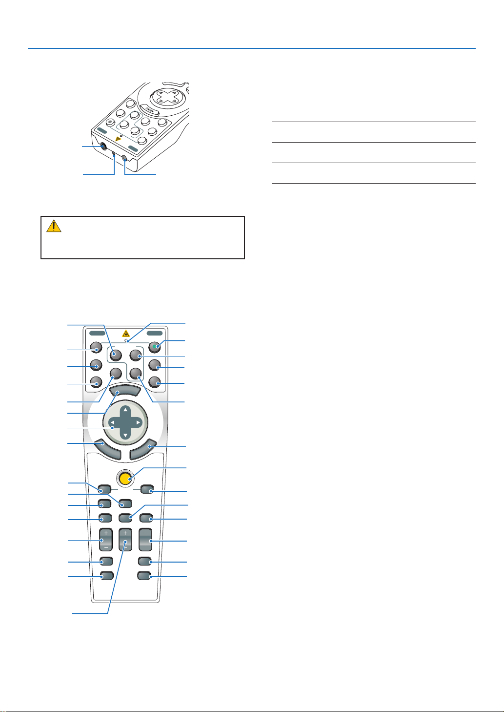
Part Names of the Remote Control
LASER
3D REFORM
AUTO ADJ.
ASPECT
HELP
PICTURE
PIC-MUTE
LAMP MODE
R-CLICKL-CLICK
MOUSE
FREEZE
PIP
VOLUME MAGNIFY
PAGE
SELEC T
M
E
N
U
E
N
T
E
R
E
X
I
T
OFF
VIDEO
S-VIDEO
VIEWER
NETWORK
COMPUTER
COMPONENT
ON
POWERPOWER
3
1
2
UP
DOWN
5
8
9
4
6
7
10
11
12
13
14
21
23
22
24
25
26
27
28
20
30
31
32
33
29
19
15
16
17
18
OFF
VIDEO
S-VIDEO
VIEWER
NETWORK
COMPUTER
COMPONENT
ON
POWER
POWER
R
3
1
2
SELECT
2
1
3
1. Introduction
4. LED
Flashes when any button is pressed.
5. POWER ON Button (
NOTE: To turn on the projector, press and hold the POWER
ON button for a minimum of two seconds.
→
page
23)
1. Laser Pointer
CAUTION:
* Do not look into the laser pointer while it is on.
* Do not point the laser beam at a person.
2. Infrared Transmitter
3. Remote jack (→ page 11)
6. POWER OFF Button (
→
page 34)
NOTE: To turn off the projector, press the POWER OFF button twice.
7. COMPUTER 1 Button (
→
page
25)
8. COMPUTER 2 Button (→ page 25)
page
→
page
→
page
→
→
page
25)
25)
→
page
25, 65)
page
25)
25)
25)
9. COMPUTER 3 Button (
10. VIDEO Button (
→
11. S-VIDEO Button (
12. COMPONENT Button (
13. VIEWER Button (
14. NETWORK Button (
15. MENU Button
16. SELECT
Button
17. ENTER Button
18. EXIT Button
19. LASER Button (
20. MOUSE R-CLICK Button (
21. MOUSE L-CLICK Button (
22. FREEZE Button (
23. PIP Button (
24. ASPECT Button (
25. VOLUME +/− Buttons (
26. PICTURE Button (
27. PIC-MUTE Button (
28. MAGNIFY +/− Buttons (
29. LAMP MODE Button (
30. AUTO ADJ. Button (
31. PAGE UP/DOWN Buttons (
32. 3D REFORM Button (
33. HELP Button (→ page 36)
→
→
→
page 43)
page 33)
page 35)
→
page 93)
→
page 3
→
page 88, 90)
→
page 35)
→
page 35)
→
page 3
→
page 3
→
page 30, 40)
→
page 39)
→
page 39)
6)
2)
→
page 39)
2)
9
Page 24
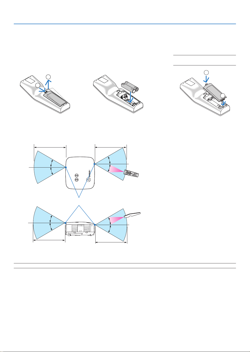
Battery Installation
2
1
2
1
30°
30°
30°
30°
30°
30°
30°
30°
1. Introduction
1
Press the catch and remove the battery cover.
2
Install new ones (AA). Ensure
that you have the batteries’ polarity (+/−) aligned correctly.
Operating Range for Wireless Remote Control
7 m/22 feet 7 m/22 feet
Remote control
3
Slip the cover back over the batteries until it snaps into place.
NOTE: Do not mix different types of
batteries or new and old batteries.
Remote sensor on projector cabinet
Remote control
7 m/22 feet
NOTE: Actual operating range may differ slightly from that shown in the drawing.
TIP: You can determine which remote sensor on the projector is enabled in wireless mode. The options are: front, rear or both. (→
page 124)
• The infrared signal operates by line-of-sight up to a distance of about 22 feet/7 m and within a 60-degree angle
of the remote sensor on the projector cabinet.
• The projector will not respond if there are objects between the remote control and the sensor, or if strong light
falls on the sensor.
Weak batteries will also prevent the remote control from properly operating the projector.
7 m/22 feet
10
Page 25
1. Introduction
WIRELESS
USB(LAN)
WIRELESS
REMOTE
LASER
3D REFORM
AUTO ADJ.
ASPECT
HELP
PICTURE
PIC-MUTE
LAMP MODE
R-CLICKL-CLICK
MOUSE
FREEZE
PIP
VOLUME MAGNIFY
PAGE
SELECT
M
E
N
U
E
N
T
E
R
E
X
I
T
OFF
VIDEO
S-VIDEO
VIEWER
NETWORK
COMPUTER
COMPONENT
ON
POWERPOWER
3
1
2
UP
DOWN
Remote Control Precautions
• Handle the remote control carefully.
• If the remote control gets wet, wipe it dry immediately.
• Avoid excessive heat and humidity.
• Do not heat, take apart, or throw batteries into fire.
• If you will not be using the remote control for a long time, remove the batteries.
• Ensure that you have the batteries’ polarity (+/−) aligned correctly.
• Do not use new and old batteries together, or use different types of batteries together.
• Dispose of used batteries according to your local regulations.
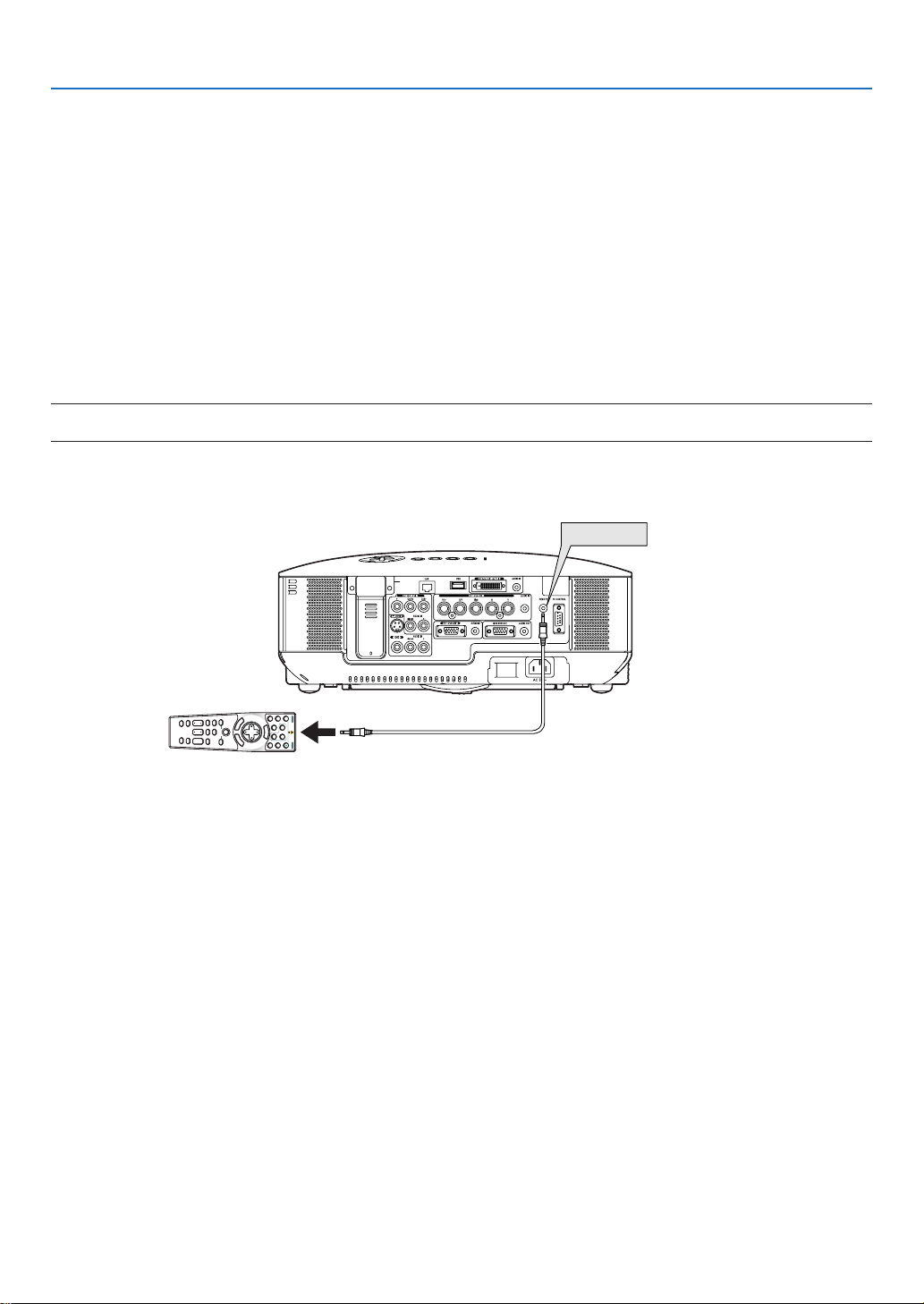
Using the Remote Control in Wired Operation
Connect one end of the supplied remote cable to the REMOTE mini jack and the other end to the remote jack on
the remote control.
When in wired operation, the remote control can operate the projector without having to install batteries.
NOTE:
• Connecting the remote cable to the REMOTE mini jack on the terminal panel will make the wireless operation unavailable.
11
Page 26
1
3
2
2. Installation and Connections
300
"
240
"
Distance (Unit: m/inch)
Lens center
Screen Size
Screen Size (unit: cm/inch)
609.6 (W) X 457.2 (H) / 240 (W) X 180 (H)
487.7 (W) X 365.8 (H) / 192 (W) X 144 (H)
406.4 (W) X 304.8 (H) / 160 (W) X 120 (H)
304.8 (W) X 228.6 (H) / 120 (W) X 90 (H)
243.8 (W) X 182.9 (H) / 96 (W) X 72 (H)
203.2 (W) X 152.4 (H) / 80 (W) X 60 (H)
162.6 (W) X 122.0 (H) / 64 (W) X 48 (H)
121.9 (W) X 91.4 (H) / 48 (W) X 36 (H)
81.3 (W) X 61.0 (H) / 32 (W) X 24 (H)
200
"
150
"
120
"
100
"
80
"
10.9/429.1"
8.7/342.5"
7.3/287.4"
5.4/212.6"
4.3/169.3"
3.6/141.7"
2.9/114.2"
2.1/82.68"
1.4/
55.12"
40
"
60
"
L
A
M
P
S
T
A
T
U
S
P
O
W
E
R
O
N
/
S
T
A
N
D
B
Y
S
O
U
R
C
E
A
U
T
O
A
D
J
U
S
T
3
D
R
E
F
O
R
M
SELECT
U
S
B
LEN
S SHI
FT
LEFT RIGH
T
D
O
W
N
U
P
WIRELESS
WIRELESS
This section describes how to set up your projector and how to connect PCs, video and audio sources.
Your projector is simple to set up and use.
But before you get started, you must first:
Set up a screen and the projector.
z
Connect your computer or video equip-
x
ment to the projector. See pages 14 -
21.
Connect the supplied power cable.
c
See page 22.
NOTE: Ensure that the power cable and any
other cables are disconnected before moving the
projector. When moving the projector or when it
is not in use, cover the lens with the lens cap.
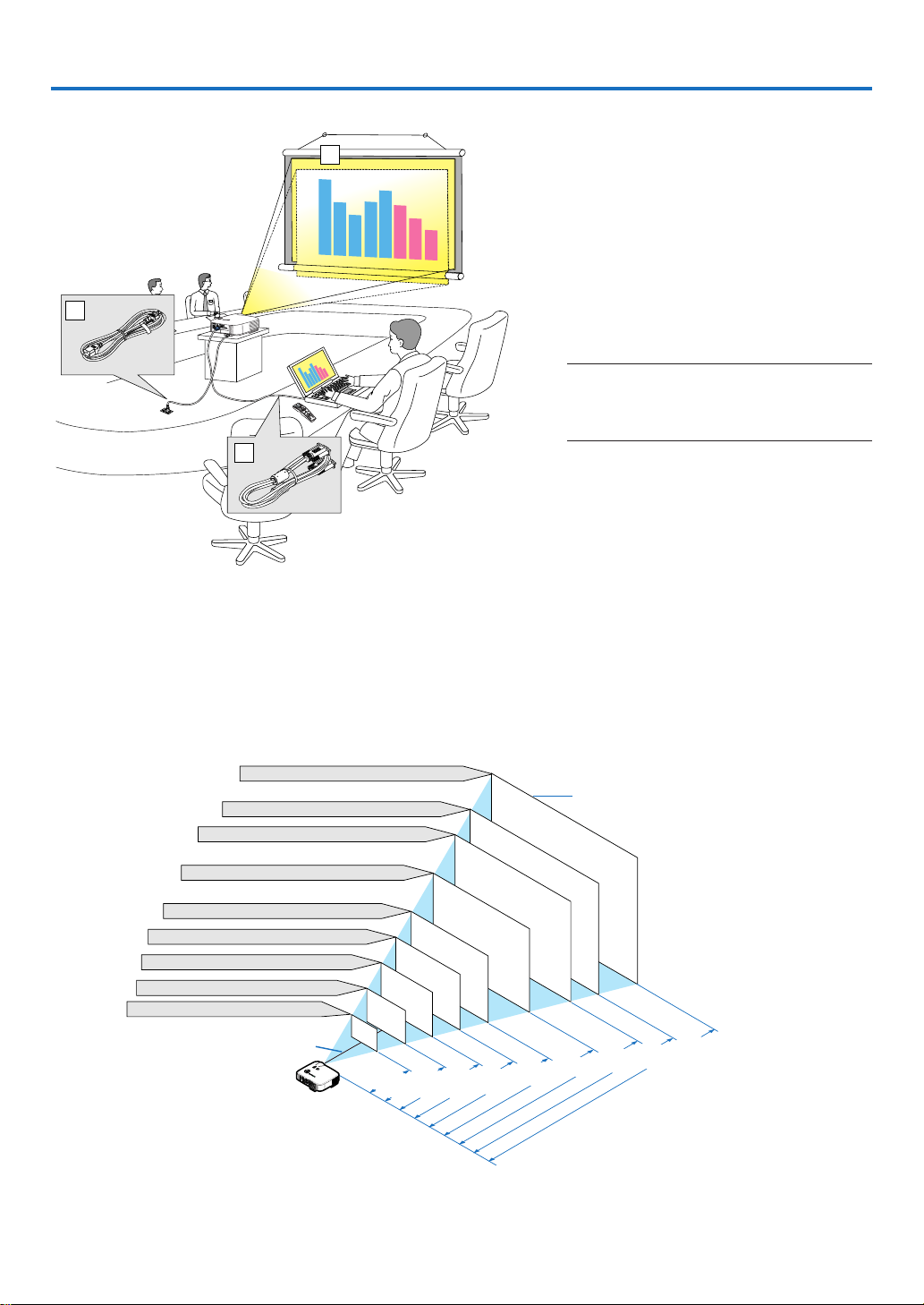
Setting Up the Screen and the Projector
Selecting a Location [NP3250/NP2250/NP1250]
The further your projector is from the screen or wall, the larger the image. The minimum size the image can be is
approximately 30 inches (0.76 m) measured diagonally when the projector is roughly 41 inches (1.0 m) from the
wall or screen. The largest the image can be is 500 inches (12.7 m) when the projector is about 718 inches (18.2 m)
from the wall or screen. Use the drawing below as a guide.
TIP: The screen sizes above are intermediate values between tele (minimum display area) and wide (maximum display area) when
the standard lens is used. Image size can be adjusted with the zoom adjustment up to a maximum of 15%.
For optional lenses, see page 139.
12
Page 27
2. Installation and Connections
300
"
240
"
Distance (Unit: m/inch)
Lens center
Screen Size
Screen Size (unit: cm/inch)
646.2 (W) X 403.9 (H) / 254 (W) X 159 (H)
516.9 (W) X 323.1 (H) / 204 (W) X 127 (H)
430.8 (W) X 269.2 (H) / 170 (W) X 106 (H)
323.1 (W) X 201.9 (H) / 127 (W) X 79 (H)
258.5 (W) X 161.5 (H) / 102 (W) X 64 (H)
215.4 (W) X 134.6 (H) / 85 (W) X 53 (H)
172.3 (W) X 107.7 (H) / 68 (W) X 42 (H)
129.2 (W) X 80.8 (H) / 51 (W) X 32 (H)
86.2 (W) X 53.8 (H) / 34 (W) X 21 (H)
200
"
150
"
120
"
100
"
80
"
11.5/452.5"
9.2/361.5"
7.6/301"
5.7/225"
4.6/179.5"
3.8/149.5"
3.0/119"
2.3/89"
1.5/
58.5"
40
"
60
"
L
A
M
P
S
T
A
T
U
S
P
O
W
E
R
O
N
/
S
T
A
N
D
B
Y
S
O
U
R
C
E
A
U
T
O
A
D
J
U
S
T
3
D
R
E
F
O
R
M
SELECT
U
S
B
LENS S
HIFT
LE
FT RIGHT
D
O
W
N
U
P
WIRELESS
WIRELESS
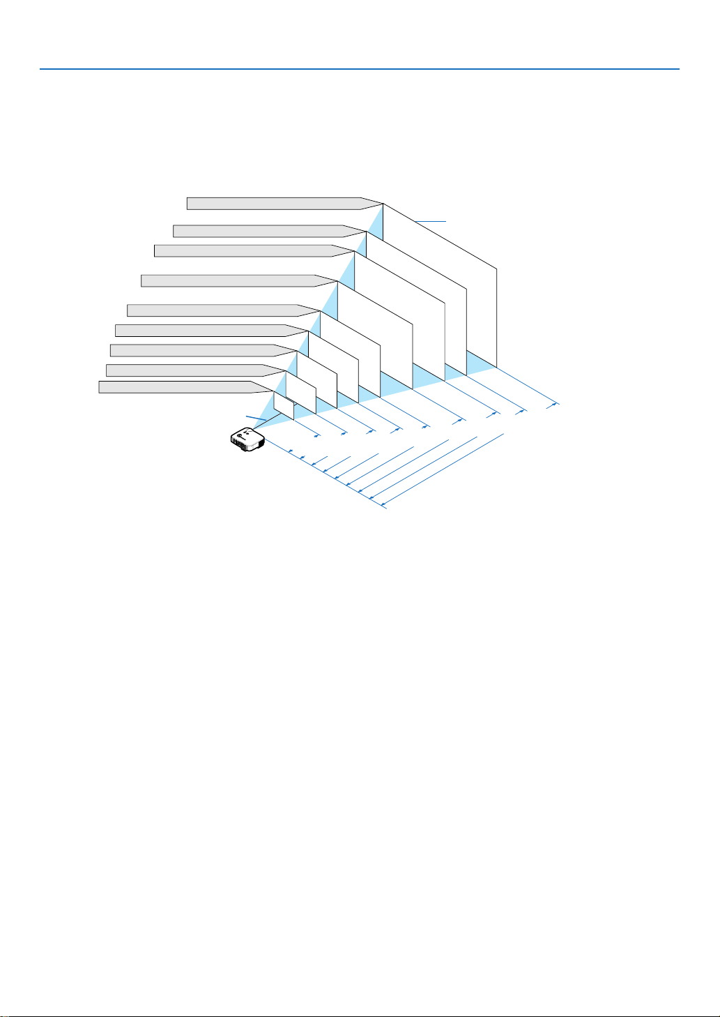
Selecting a Location [NP3250W]
The further your projector is from the screen or wall, the larger the image. The minimum size the image can be is
approximately 30 inches (0.76 m) measured diagonally when the projector is roughly 44 inches (1.1 m) from the
wall or screen. The largest the image can be is 500 inches (12.7 m) when the projector is about 756 inches (19.2 m)
from the wall or screen. Use the drawing below as a guide.
TIP: The screen sizes above are intermediate values between tele (minimum display area) and wide (maximum display area) when
the standard lens is used. Image size can be adjusted with the zoom adjustment up to a maximum of 15%.
For optional lenses, see page 140.
13
Page 28
WIRELESS
USB(LAN)
WIRELESS
COMPUTER 1 IN
COMPUTER 2 IN
PHONE
2. Installation and Connections
Making Connections
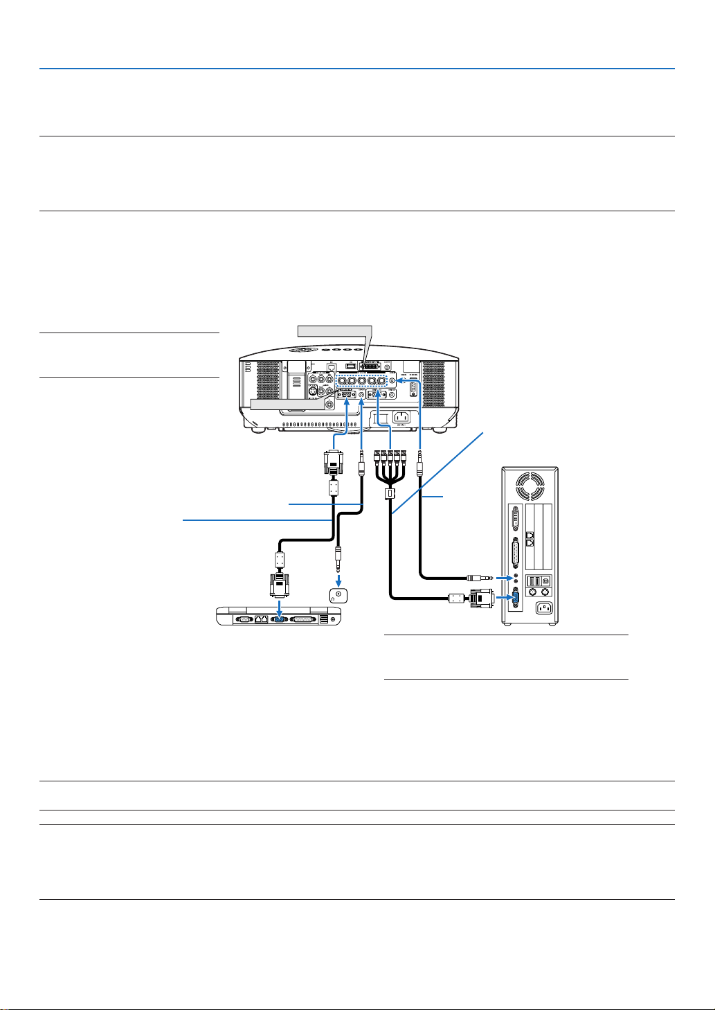
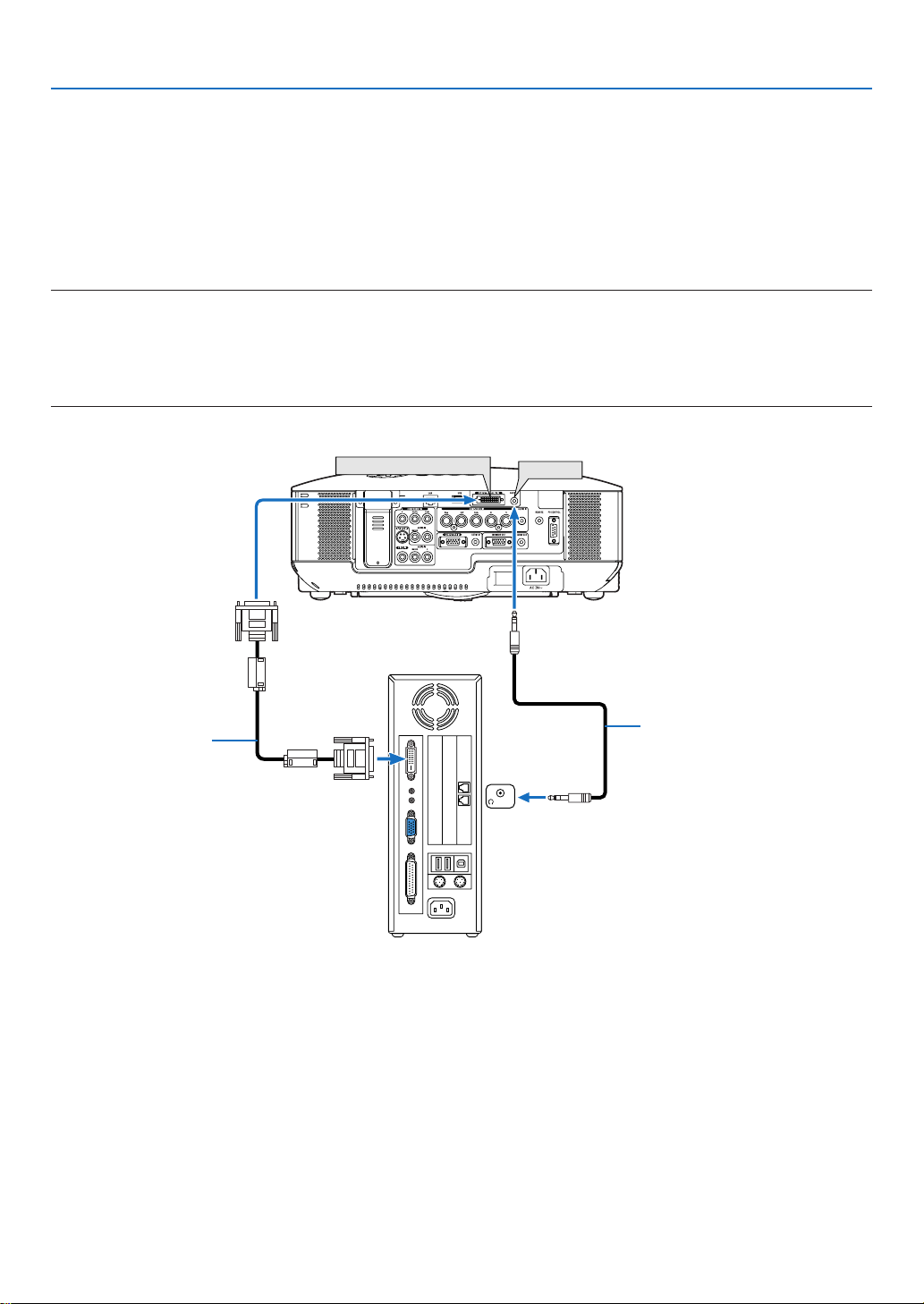
Connecting Your PC or Macintosh Computer
NOTE: When using with a notebook PC, be sure to connect the projector and notebook PC while the projector is in standby mode
and before turning on the power to the notebook PC.
In most cases the output signal from the notebook PC is not turned on unless connected to the projector before being powered up.
* If the screen goes blank while using your remote control, it may be the result of the computer’s screen-saver or power manage-
ment software.
Enabling the computer’s external display
Displaying an image on the notebook PC’s screen does not necessarily mean it outputs a signal to the projector.
When using a PC compatible laptop, a combination of function keys will enable/disable the external display.
Usually, the combination of the “Fn” key along with one of the 12 function keys gets the external display to come on
or off. For example, NEC laptops use Fn + F3, while Dell laptops use Fn + F8 key combinations to toggle through
external display selections.
NOTE: Both COMPUTER 1 IN and
COMPUTER 3 (DVI-D) IN connectors
support Plug & Play (DDC2B).
BNC × 5 cable (not supplied)
Audio cable (not supplied)
VGA signal cable (supplied)
To mini D-Sub 15-pin connector on the
projector. It is recommended that you use
a commercially available distribution amplifier if connecting a signal cable longer
than the one supplied.
IBM VGA or Compatibles (Notebook
type) or Macintosh (Notebook type)
NOTE: For older Macintosh, use a commercially
available pin adapter (not supplied) to connect to
your Mac’s video port.
Audio
cable (not
supplied)
• First turn off the computer and the projector before making connections.
• Turn down the volume on the computer before connecting an audio cable to the headphone jack of the com-
puter. After connecting the computer to the projector, you can adjust the sound level on the computer and the
projector to your preference.
• You are recommended to connect an audio cable to an audio out connector (mini jack type) if any.
NOTE: The NP3250/NP2250/NP1250/NP3250W is not compatible with video decoded outputs of either the NEC ISS-6020 and
ISS-6010 switchers.
NOTE:
An image may not be displayed correctly when a Video or S-Video source is played back via a commercially available scan converter.
This is because the projector will process a video signal as a computer signal at the default setting. In that case, do the following.
* When an image is displayed with the lower and upper black portion of the screen or a dark image is not displayed correctly:
Project an image to fill the screen and then press the AUTO ADJ button on the remote control or the AUTO ADJUST button on
the projector cabinet.
14
Page 29
WIRELESS
USB(LAN)
WIRELESS
COMPUTER 3 (DVI-D) IN
PHONE
AUDIO IN
2. Installation and Connections
When Viewing a DVI Digital Signal
To project a DVI digital signal, be sure to connect the PC and the projector using a DVI-D signal cable (not supplied)
before turning on your PC or projector. Turn on the projector first and select COMPUTER 3 from the source menu
before turning on your PC.
Failure to do so may not activate the digital output of the graphics card resulting in no picture being displayed.
Should this happen, restart your PC.
Do not disconnect the DVI-D signal cable while the projector is running. If the signal cable has been disconnected
and then re-connected, an image may not be correctly displayed. Should this happen, restart your PC.
NOTE:
• Use a DVI-D cable compliant with DDWG (Digital Display Working Group) DVI (Digital Visual Interface) revision 1.0 standard.
The DVI-D cable should be within 5 m (197") long.
• The DVI (DIGITAL) connector (COMPUTER 3 (DVI-D) IN) accepts VGA (640 × 480), SVGA (800 × 600), 1152 × 864, XGA
(1024 × 768), SXGA (1280 × 1024 @ up to 60Hz), SXGA+ (1400 × 1050 @ up to 60Hz), WXGA (1280 × 768, 1280 × 800), and
WXGA+ (1440 × 900 @ up to 60Hz).
(DVI-D connector with HDCP)
DVI-D cable
(not supplied)
IBM VGA or Compatibles or Macintosh
Audio cable (not supplied)
What is HDCP/HDCP technology?
HDCP is an acronym for High-bandwidth Digital Content Protection. High bandwidth Digital Content Protection
(HDCP) is a system for preventing illegal copying of video data sent over a Digital Visual Interface (DVI).
If you are unable to view material via the DVI input, this does not necessarily mean the projector is not functioning
properly. With the implementation of HDCP, there may be cases in which certain content is protected with HDCP
and might not be displayed due to the decision/intention of the HDCP community (Digital Content Protection, LLC).
15
Page 30
AUDIO
IN
WIRELESS
USB(LAN)
WIRELESS
AUDIO OUT
PHONE
MONITOR OUT
COMPUTER 1 IN (or COMPUTER 2 IN / COMPONENT IN)
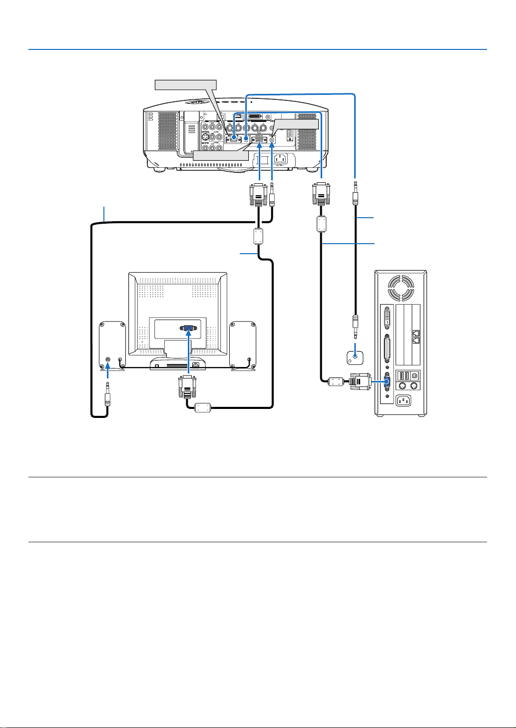
Connecting an External Monitor
Audio cable (not supplied)
2. Installation and Connections
Audio cable (not supplied)
VGA signal cable (not supplied)
VGA signal cable (supplied)
You can connect a separate, external monitor to your projector to simultaneously view on a monitor the RGB analog or component image you’re projecting.
NOTE:
• Daisy chain connection is not possible.
• The MONITOR OUT connector will output no video signal (Digital signal) from the COMPUTER 3 (DVI-D) IN connector.
• When audio equipment is connected, the projector speaker is disabled.
• When the projector is in standby condition, the MONITOR OUT connector outputs the last displayed video signal and the AU-
DIO OUT jack outputs the last audio signal. The sound level remains at the previous level set for the last input used.
16
Page 31

AUDIO IN
L R
AUDIO OUT
L R
Component
Y Cb Cr
WIRELESS
USB(LAN)
WIRELESS
COMPONENT IN
AUDIO IN
Connecting Your DVD Player with Component Output
Audio Equipment
DVD player
2. Installation and Connections
Component video RCA × 3
cable (not supplied)
Audio cable (not supplied)
TIP: A component signal will be automatically displayed. If not, from the menu, select [SETUP]
LECT]
→
[COMPUTER 1 (or 2)]
→
[COMPONENT].
→
[OPTIONS]
→
[SIGNAL SE-
• When connecting to the COMPUTER 2 IN, use a commercially available RCA (female)-to-BNC(male) adapter.
NOTE: Refer to your DVD player’s owner’s manual for more information about your DVD player’s video output requirements.
17
Page 32

AUDIO IN
L R
AUDIO OUT
L R
VIDEO OUT
S-VIDEO VIDEO
WIRELESS
USB(LAN)
WIRELESS
S-VIDEO IN
VIDEO IN
AUDIO IN
Connecting Your VCR
VCR
2. Installation and Connections
S-Video cable (not supplied)
Video cable (not supplied)
Audio equipment
Audio cable (not supplied)
NOTE: Refer to your VCR owner’s manual for more information about your equipment’s video output requirements.
NOTE: An image may not be displayed correctly when a Video or S-Video source is played back in fast-forward or fast-rewind via
a scan converter.
18
Page 33

2. Installation and Connections
Connecting to a Network
The NP3250/NP2250/NP1250/NP3250W comes standard with a LAN port (RJ-45) which provides a LAN connection using a LAN cable. The USB Wireless LAN Unit also provides a wireless LAN connection. To use a LAN connection, you are required to assign an IP address to the projector. For setting the NETWORK, see page 110. (From
the menu, select [SETUP] → [INSTALLATION(2)] → [NETWORK SETTINGS])
NOTE: Some projectors may not have the USB Wireless LAN Unit. If you own a projector without the USB Wireless LAN Unit installed and need to present to the projector via a wireless connection, the optional USB Wireless LAN Unit must be installed.
With the LAN connection, two features are available: Projector control and Picture transmission.
Projector control feature
With the wired or wireless LAN connection, you can control (power on/off, input select, etc.) and receive information
from the projector over the network using a computer. The following three methods are available:
* Using the HTTP Server feature on the projector. (
* Using PC Control Utility 3.0 from the supplied User Supportware 6 CD-ROM.
* Using Image Express Utility 2.0 from the supplied User Supportware 6 CD-ROM.
→
page 53)
Picture transmission feature (Using WindowsVista)
A Windows Vista-based computer can be operated using the projector over a network. The projector supports the
Network Projector function and the Remote Desktop function of Windows Vista. (→ page 56, 60)
Picture transmission feature (Using User Supportware 6 CD-ROM)
With the wired or wireless LAN connection, you can send images and slides from a personal computer to the projector which then can be projected on the screen. The following two methods are available:
* Using Image Express Utility 2.0 from the supplied User Supportware 6 CD-ROM.
* Using ArcSoft MediaImpression from the supplied User Supportware 6 CD-ROM.
With the USB mouse connected to the projector, you can also operate the desktop screen on your Windows PC
connected to the LAN or the wireless LAN.
* Using Desktop Control Utility 1.0 from the supplied User Supportware 6 CD-ROM.
TIP: Five Windows software programs (Image Express Utility 2.0, Desktop Control Utility 1.0, ArcSoft MediaImpression, Viewer
PPT Converter and PC Control Utility 3.0) and a Macintosh software program (Image Express Utility 2 for Mac OS X) are contained on the supplied Projector User Supportware 6 CD-ROM. For their functions and operations, see the user’s guides (PDF)
contained on the same CD-ROM.
• For the procedure to connect the projector with the network (wireless LAN/wired LAN), refer to “Wired and
Wireless Network Setup Guide” attached.
• For the procedure to connect Windows Vista with the network (wireless LAN/wired LAN), refer to the manual
of Windows Vista.
Viewer function supporting network
* Using the Viewer function, image and movie files stored in a shared folder in a computer connected to a net-
work can be projected. (→ page 73)
* The Viewer supports the “Media Sharing” function in Windows Media Player 11. (→ page 77)
NOTE: A LAN card on your computer must be compatible with Wi-Fi (IEEE802.11a/b/g) standard.
19
Page 34

Example of LAN connection
WIRELESS
USB(LAN)
WIRELESS
LAN
Wireless access point
Wired LAN
USB Wireless LAN Unit
(A) Example of wired LAN connection
2. Installation and Connections
Server
Hub
LAN cable (not supplied)
NOTE: Use a Category 5 or higher LAN cable.
(B) Example of wireless LAN connection
(Network Type → Infrastructure)
PC with wireless
LAN card inserted
PC with built-in wireless
LAN function
To make connection with a wireless LAN via a wireless access point, you need to select the Infrastructure mode.
From the menu, select [SETUP] → [INSTALLATION(2)] → [NETWORK SETTINGS] → [WIRELESS] → [ADVANCED] → [CONNECTION] → [NETWORK TYPE] → [INFRASTRUCTURE].
20
Page 35

2. Installation and Connections
USB Wireless LAN Unit
(C) Example of wireless LAN connection (Network Type
PC with wireless
LAN card inserted
→
Ad Hoc)
PC with built-in wireless
LAN function
To enable direct communication (i.e., peer-to-peer) between personal computers and projectors, you need to
select the Ad Hoc mode.
From the menu, select [SETUP] → [INSTALLATION(2)] → [NETWORK SETTINGS] → [WIRELESS] → [ADVANCED] → [CONNECTION] → [NETWORK TYPE] → [AD HOC].
The Ad Hoc mode complies with IEEE802.11 standard.
21
Page 36

2. Installation and Connections
LAMP
STATUS
POWER
ON/STAND BY
SOURCE
AUTO ADJUST
3D REFORM
SELECT
USB
LENS SHIFT
LEFT
RIGHT
DOWN
UP
WIRELESS
WIRELESS
Make sure that the prongs are fully
inserted into both the AC IN and the
wall outlet.
To wall outlet
LENS SHIF
T
LEFT
Connecting the Supplied Power Cable
Connect the supplied power cable to the projector.
First connect the supplied power cable’s three-pin plug to the AC IN of the projector, and then connect the other
plug of the supplied power cable in the wall outlet.
About Direct Power Off
The projector has a feature called “Direct Power Off”. This feature allows the projector to be turned off (even when
projecting an image) using the Main Power Switch or disconnecting the AC power supply.
NOTE: Before using Direct Power Off, be sure to allow at least 20 minutes immediately after turning on the projector and starting
to display an image.
CAUTION:
Do not try to touch the ventilation outlet on the left front (when seen from the front) as it can become heated
while the projector is turned on and immediately after the projector is turned off.
CAUTION:
Do not unplug the power cable from the wall outlet or projector when the projector is powered on. Doing so can
cause damage to the AC IN connector of the projector and (or) the prong plug of the power cable.
NOTE: To turn off the AC power supply when the projector is powered on, use a power strip equipped with a switch and a breaker.
22
Page 37

OFF
VIDEO
S-VIDEO
VIEWER
NETWORK
COMPUTER
COMPONENT
ON
SELECT
POWERPOWER
M
E
N
U
E
N
T
E
R
E
X
I
T
3
1
2
USB
LAMP
STATUS
POWER
ON/STAND BY
SOURCE
AUTO ADJUST
3D REFORM
3. Projecting an Image (Basic Operation)
POWER
POWER POWER
STATUS
LAMP
STATUS
LAMP
STATUS
LAMP
ON/STAND BY
LAMP
STATUS
POWER
ON/STAND BY
SOURCE
AUTO ADJUST
3D REFORM
SELECT
USB
LENS SHIFT
LEFT
RIGHT
D
O
W
N
UP
WIRELESS
WIRELESS
USB
LAMP
STATUS
POWER
LENS SHIFT
LEFT
RIGHT
D
O
W
N
UP
This section describes how to turn on the projector and to project a picture onto the screen.
Turning on the Projector
NOTE:
• The projector has two power switches: a main power switch and a POWER (ON/STAND BY) button (POWER ON and OFF on the
remote control).
• When plugging in or unplugging the supplied power cable, make sure that the main power switch is pushed to the off () position. Failure to do so may cause damage to the projector.
• The projector has a feature to prevent itself from being used by unauthorized individuals. To use this feature, register a keyword. (→ page 45)
1. Remove the lens cap.
• Do not try to remove the lens cap by pulling on the
string. Doing so can cause damage.
2. To turn on the main power to the projector, press the
Main Power switch to the on position ( I ).
• The projector will go into standby mode. When in stand-
by mode, the POWER indicator will light orange and the
STATUS indicator will light green.
3. After making sure that the projector is in standby
mode, press the POWER (ON/STAND BY) or POWER
(ON) button for a minimum of 2 seconds when the
STATUS indicator goes off and the POWER indicator
starts blinking.
When the POWER indicator turns a steady green,
and the projector is ready to use.
• After you turn on your projector, ensure that the comput-
er or video source is turned on and that your lens cap is
removed.
Standby Blinking Power On
Steady green /
orange light
(→ page 144)
NOTE: When no signal is available, a blue, black or logo screen is displayed.
Blinking green
Press this button for a
minimum of 2 seconds.
light
Steady green
light
23
Page 38

OFF
VIDEO
S-VIDEO
VIEWER
NETWORK
COMPUTER
COMPONENT
ON
POWERPOWER
M
E
N
U
E
N
T
E
R
E
X
I
T
3
1
2
SELECT
3. Projecting an Image (Basic Operation)
OFF
VIDEO
S-VIDEO
VIEWER
NETWORK
COMPUTER
COMPONENT
ON
SELECT
POWERPOWER
3
1
2
M
E
N
U
E
N
T
E
R
E
X
I
T
SOURCE
AUTO ADJUST
3D REFORM
SELECT
SOURCE
AUTO ADJUST
3D REFORM
SELECT
Note on Startup screen (Menu Language Select screen)
When you first turn on the projector, you will get the Startup menu. This menu gives you the opportunity to select
one of the 21 menu languages.
To select a menu language, follow these steps:
1. Use the SELECT
button to select one of the 21 lan-
guages for the menu.
2. Press the ENTER button to execute the selection.
After this has been done, you can proceed to the menu
operation.
If you want, you can select the menu language later. (→
[LANGUAGE] on page 105)
NOTE:
• The projector cannot be turned off for 60 seconds after the lamp is turned on and while the POWER indicator is blinking green.
• If you turn on the projector immediately after the lamp is turned off or when the ambient temperature is high, the cooling fans
will run for a moment and then you will get an image on the screen.
• Immediately after turning on the projector, screen flicker may occur. This is normal. Wait 3 to 5 minutes until the lamp lighting
is stabilized.
• When the [LAMP MODE] is set to [ECO], the Lamp indicator will light green.
• If one of the following things happens, the projector will not turn on.
- If the internal temperature of the projector is too high, the projector detects abnormal high temperature. In this
condition the projector will not turn on to protect the internal system. If this happens, wait for the projector’s
internal components to cool down.
- When the lamp reaches its end of usable life, the projector will not turn on. If this happens, replace the lamp.
→
(
page 136)
- If the lamp fails to light, and if the STATUS indicator flashes on and off in a cycle of six times, wait a full minute
and then turn on the power.
NOTE: Turning the Main Power Switch Off then Back On
Allow a minimum of one second between turning off the main power switch and turning it back on again.
The same will be applied when a power strip equipped with a switch and a breaker is used.
Failing to do so could result in no power to the projector. (There will be no stand-by LED)
Should this happen, unplug the power cable and plug it in again. Turn on the main power switch.
24
Page 39

3. Projecting an Image (Basic Operation)
OFF
ON
SELECT
POWERPOWER
M
E
N
U
E
N
T
E
R
E
X
I
T
VIDEO
S-VIDEO
VIEWER
NETWORK
COMPUTER
COMPONENT
3
1
2
POWER
AUTO ADJUST
USB
LAMP
STATUS
ON/STAND BY
SOURCE3D REFORM
SELECT
POWER
AUTO ADJUST
USB
LAMP
STATUS
ON/STAND BY
SOURCE3D REFORM
SELECT
Selecting a Source
Selecting the computer or video source
Selecting from Source List
Press and quickly release the SOURCE button on the projector cabinet to display the Source list. Each time the SOURCE button is pressed, the input source
will change as follows: “COMPUTER 1/2/3”, “COMPONENT”, “VIDEO” (VCR),
“S-VIDEO”, “VIEWER” (slides on a USB memory) or “NETWORK” (LAN port
[RJ-45] or installed USB wireless LAN unit).
To display the selected source, press the ENTER button.
Detecting the Signal Automatically
Press and hold the SOURCE button for a minimum of 1 second, the projector
will search for the next available input source. Each time you press and hold the
SOURCE button for a minimum of 1 second, the input source will change as follows:
COMPUTER1 → COMPUTER2 → COMPUTER3 → COMPONENT → VIDEO
→
S-VIDEO → VIEWER → COMPUTER1 → ...
If no input signal is present, the input will be skipped. When the input source
you wish to project is displayed, release the button.
Using the Remote Control
Press any one of the COMPUTER 1/2/3, COMPONENT, VIDEO, S-VIDEO,
VIEWER or NETWORK buttons.
25
Page 40

3. Projecting an Image (Basic Operation)
L
A
M
P
S
T
A
T
U
S
P
O
W
E
R
O
N
/
S
T
A
N
D
B
Y
S
O
U
R
C
E
A
U
T
O
A
D
J
U
S
T
3
D
R
E
F
O
R
M
S
ELE
CT
U
S
B
L
E
N
S
S
H
IF
T
L
E
F
T
R
IG
H
T
D
O
W
N
U
P
WIRELESS
WIRELESS
L
A
M
P
S
T
A
T
U
S
P
O
W
E
R
O
N
/
S
T
A
N
D
B
Y
S
O
U
R
C
E
A
U
T
O
A
D
J
U
S
T
3
D
R
E
F
O
R
M
S
EL
EC
T
U
S
B
L
E
N
S
S
H
IF
T
L
E
F
T
R
I
G
H
T
D
O
W
N
U
P
WIRELESS
WIRELESS
L
A
M
P
S
T
A
T
U
S
P
O
W
E
R
O
N
/
S
T
A
N
D
B
Y
S
O
U
R
C
E
A
U
T
O
A
D
J
U
S
T
3
D
R
E
F
O
R
M
SELE
C
T
U
S
B
L
E
N
S
S
H
I
F
T
L
E
F
T
R
IG
H
T
D
O
W
N
U
P
WIRELESS
WIRELESS
L
A
M
P
S
T
A
T
U
S
P
O
W
E
R
O
N
/
S
T
A
N
D
B
Y
S
O
U
R
C
E
A
U
T
O
A
D
J
U
S
T
3
D
R
E
F
O
R
M
S
E
LE
CT
U
S
B
L
E
N
S
S
H
IF
T
L
E
F
T
R
IG
H
T
D
O
W
N
U
P
WIRELESS
WIRELESS
L
A
M
P
S
T
A
T
U
S
P
O
W
E
R
O
N
/
S
T
A
N
D
B
Y
S
O
U
R
C
E
A
U
T
O
A
D
J
U
S
T
3
D
R
E
F
O
R
M
SE
LEC
T
U
S
B
L
E
N
S
S
H
IF
T
L
E
F
T
R
IG
H
T
D
O
W
N
U
P
WIRELESS
WIRELESS
L
A
M
P
S
T
A
T
U
S
P
O
W
E
R
O
N
/
S
T
A
N
D
B
Y
S
O
U
R
C
E
A
U
T
O
A
D
J
U
S
T
3
D
R
E
F
O
R
M
S
ELE
CT
U
S
B
L
E
N
S
S
H
IF
T
L
E
F
T
R
I
G
H
T
D
O
W
N
U
P
WIRELESS
WIRELESS
Adjusting the Picture Size and Position
Use the lens shift dials, the adjustable tilt foot levers, the zoom lever or the focus ring to adjust the picture size and
position.
Adjusting the position of a projected image
[Lens shift]
(→ page 27)
Adjusting the throw angle (the height of an image)
[Tilt foot] *¹
Adjusting the focus
[Focus ring]
Finely adjusting the size of an image
[Zoom lever]
Adjusting the left and right tilt of an image
[Tilt foot]
Adjusting the keystone correction
[Keystone] *²
NOTE*1: Adjust the throw angle (the height of an image) when the image position is higher than the lens shift adjustable range.
NOTE*2: See “
Correcting Keystone Distortion” on page 30 for Keystone.
* In the above drawings, cables are omitted for clarity.
26
Page 41

3. Projecting an Image (Basic Operation)
LAMP
STATUS
POW
ER
ON/STAND BY
SOU
R
C
E
A
U
T
O AD
JU
S
T
3
D
R
E
FOR
M
SELECT
USB
SELECT
L
E
N
S
S
H
IF
T
L
E
F
T
R
I
G
H
T
D
O
W
N
UP
WIRELESS
WIRELESS
LENS SHIFT
LEFT RIGHT
DOWN
UP
Desktop front projection
Ceiling front projection
Vertical shift
Vertical shift
Max. 0.5V
Max.
0.5V
1V
0.5V
0.1H
0.1H 1H
Width of projected image
Shift to left Shift to right
1V
Normal projection
Position
Adjusting the position of a projected image
• Rotate the lens shift dial.
NOTE: The lens shift dial for LEFT-RIGHT cannot be rotated one-half turn or more.
Do not over rotate it or it may break.
NOTE: Shifting the lens to the maximum in two directions combined will cause the edges of the image to become dark or will
cause some shadows.
TIP: The lens shift dial for UP-DOWN can be rotated one turn or more, but not beyond the adjustable range defined below.
NOTE: Lens shift is not available with the NP01FL optional lens. The NP01FL should be used only for “zero degree” applications.
27
Page 42

3. Projecting an Image (Basic Operation)
Focus ring
L
AM
P
STATUS
POWER
ON/STAND BY
SOU
RCE
A
UTO
AD
JU
ST
3D
REFO
RM
SELECT
U
SB
L
E
N
S
S
H
IF
T
L
E
F
T
R
IG
H
T
D
O
W
N
UP
WIRELESS
WIRELESS
LENS RELEASE
LENS RELEASE
LAM
P
STATUS
POW
ER
ON/STAND BY
SO
UR
CE
AU
TO
AD
JUS
T
3D
R
EFOR
M
SELECT
US
B
L
E
N
S
S
H
IF
T
L
E
F
T
R
IG
H
T
D
O
W
N
UP
WIRELESS
WIRELESS
Zoom lever
Adjusting the focus (Focus ring)
• Rotate the focus ring to make focus adjustment.
Finely adjusting the size of an image (Zoom lever)
• Rotate the zoom lever to adjust the image size on the screen.
28
Page 43

3. Projecting an Image (Basic Operation)
2
L
A
M
P
S
T
A
T
U
S
P
O
W
E
R
S
O
U
R
C
E
A
U
T
O
A
D
J
U
S
T
3
D
R
E
F
O
R
M
O
N
/S
T
A
N
D
B
Y
SELECT
U
S
B
U
S
B
L
A
M
P
S
T
A
T
U
S
P
O
W
E
R
S
O
U
R
C
E
A
U
T
O
A
D
J
U
S
T
3
D
R
E
F
O
R
M
O
N
/S
T
A
N
D
B
Y
1
2
LENS SHIFT
LEFT RIGHT
D
O
W
N
U
P
U
S
B
L
A
M
P
S
T
A
TU
S
PO
W
E
R
S
O
U
R
C
E
A
U
T
O
A
D
J
U
S
T
3
D
R
E
F
O
R
M
O
N
/S
T
A
N
D
B
Y
SELECT
3
4
4
LENS SHIFT
LEFT RIGHT
D
O
W
N
U
P
Adjusting the Tilt Foot
1. Lift the front edge of the projector.
CAUTION:
Do not try to touch the ventilation outlet during Tilt Foot adjustment
as it can become heated while the projector is turned on and during
its cool down period after it is turned off.
2.
Push up the Adjustable Tilt Foot Levers on the right and left sides
of the projector to extend the adjustable tilt feet (maximum height).
Adjustable Tilt
Foot Lever
3. Lower the front of the projector to the desired height.
4.
Release the Adjustable Tilt Foot lever to lock the Adjustable tilt foot.
There is approximately 10 degrees (up) of adjustment for the front of
the projector.
TIP: For operating the [KEYSTONE] screen, see “ Correcting Keystone Dis-
tortion” on page 30.
NOTE: Your “Keystone” correction data can be reset by pressing and holding
the 3D REFORM button for a minimum of 2 seconds.
CAUTION:
Do not use the tilt-foot for purposes other than originally intended.
Misuses such as using the tilt foot to carry or hang (from the wall or
ceiling) the projector can cause damage to the projector.
Adjustable Tilt Foot
Adjustable Tilt
Foot Lever
29
Page 44

3. Projecting an Image (Basic Operation)
Correcting Keystone Distortion
When the projector is not exactly perpendicular to the screen, keystone distortion occurs. To overcome it, you can use the
“Keystone” function, a digital technology that can adjust for keystone-type distortion, resulting in a crisp, square image.
The following procedure explains how to use the [
When the projector is placed diagonally to the screen,
When the projector is set up at an angle in relation to the screen, adjust the Horizontal option of the Keystone menu
so that the top and bottom of sides of the projected image are parallel.
1. Press the 3D REFORM button on the remote control or the projector cabinet.
The Keystone screen will be displayed on the screen.
KEYSTONE
] screen from the menu to correct trapezoidal distortions.
2. Press the SELECT button to select [VERTICAL] and then use the
SELECT or so that the left and right sides of the projected image are parallel.
* Adjust the vertical keystone distortion.
3. Align the left (or right) side of the screen with the left (or right) side
of the projected image.
• Use the shorter side of the projected image as the base.
• In the right example, use the left side as the base.
4. Press the SELECT
the SELECT or so that the top and bottom sides of the projected image are parallel.
• Adjust the horizontal keystone distortion.
button to select [HORIZONTAL] and then use
Screen frame
Projected area
Align left side
30
Page 45

3. Projecting an Image (Basic Operation)
5. Repeat steps 2 and 4 to correct keystone distortion.
6. After completing Keystone correction, press the EXIT button.
The Keystone screen will disappear.
• To perform Keystone correction again, press the 3D REFORM button
to display the Keystone screen and repeat above steps 1 to 6.
NOTE:
• If the projection angle is the same as in the last use, the previous correction setting values are retained in the memory.
• When doing Step 2, adjust the position of image so that the screen is smaller than the area of the projected area.
• To reset the 3D Reform correction setting values, press and hold the 3D REFORM button for a minimum of 2 seconds.
• Each time the 3D REFORM button is pressed, the item will change as follows: KEYSTONE → CORNERSTONE → None → KEY-
STONE → ...
For information on [CORNERSTONE], see “Correcting Horizontal and Vertical Keystone Distortion (Cornerstone)” on page 40.
• The Cornerstone adjustment will not be available during the Keystone adjustment. To perform the Cornerstone adjustment,
press and hold the 3D REFORM button for a minimum of 2 seconds to reset the Keystone correction setting values. The Keystone adjustment will not be available during the Cornerstone adjustment. To perform the Keystone adjustment, press and hold
the 3D REFORM button for a minimum of 2 seconds to reset the Cornerstone correction setting values.
• The 3D Reform feature can cause an image to be slightly blurred because the correction is made electronically.
31
Page 46

3. Projecting an Image (Basic Operation)
USB
LAMP
STATUS
POWER
ON/STAND BY
SOURCE3D REFORM
SELECT
AUTO ADJUST
SELECT
USB
LAMP
STATUS
POWER
ON/STAND BY
SOURCE
AUTO ADJUST
3D REFORM
AUTO ADJ.
LASER
3D REFORM
ASPECT
HELP
PICTURE
PIC-MUTE
LAMP MODE
R-CLICKL-CLICK
MOUSE
FREEZE
PIP
VOLUME MAGNIFY
PAGE
UP
DOWN
N
T
E
R
E
X
I
T
VOLUME
LASER
3D REFORM
AUTO ADJ.
ASPECT
HELP
PICTURE
PIC-MUTE
LAMP MODE
R-CLICKL-CLICK
MOUSE
FREEZE
PIP
MAGNIFY
PAGE
UP
DOWN
N
T
E
R
E
X
I
T
Optimizing an RGB Image Automatically
Adjusting the Image Using Auto Adjust
Optimizing an RGB image automatically.
Press the AUTO ADJUST button to optimize an RGB image automatically.
This adjustment may be necessary when you connect your computer for the first time.
[Poor picture]
[Normal picture]
NOTE:
• Some signals may take time to display or may not be displayed correctly.
• The Auto Adjust function does not work for component, video signals.
• If the Auto Adjust operation cannot optimize the RGB signal, try to adjust Clock and Phase manually. (→ page 91)
Adjusting Volume Up & Down
Sound level from the speaker and the AUDIO OUT
jack (Stereo mini) on the projector can be adjusted.
Another way to adjust volume is to use the menu.
Select [ADJUST] → [AUDIO] → [VOLUME] from
the menu.
NOTE:
• Volume control is not available with the SELECT
or button when an image is enlarged by using the
MAGNIFY (+) button or when the menu is displayed.
Increase volume
Decrease volume
32
Page 47

3. Projecting an Image (Basic Operation)
LA
SER
LASER
L
A
M
P
S
T
A
T
U
S
P
O
W
E
R
O
N
/
S
T
A
N
D
B
Y
SOURCE
AUTO ADJUST
3D REFORM
SELECT
U
S
B
LENS SHIFT
LEFT
RIGHT
D
O
W
N
UP
WIRELESS
WIRELESS
ON
OFF
Using the Laser Pointer
You can use the laser to draw your audience’s attention to a red dot that you can place on any object.
CAUTION:
• Do not look into the laser pointer while it is on.
• Do not point the laser beam at a person.
• Do not allow children to use the laser pointer.
Press and hold the LASER button to activate the laser pointer.
Setting the function switch
There are two switches on the bottom of the battery case: an applicable projector selector switch (1) and laser enable/disable switch (2). Check the projector being used and decide whether to enable or disable laser, then set
these switches as necessary using the tip of a thin ball-point pen. On this model, an applicable projector selector
switch (1) is not used.
Switch (2)
ON .........................
Enabled (the laser lights when the LASER button is pressed) [Factory default]
OFF ........................Disabled (the laser does not light even when the LASER button is pressed)
Disable the laser when using in an environment in which the unit is accessible to children.
33
Page 48

OFF
VIDEO
S-VIDEO
VIEWER
NETWORK
COMPUTER
COMPONENT
ON
SELECT
POWERPOWER
M
E
N
U
E
N
T
E
R
E
X
I
T
3
1
2
3. Projecting an Image (Basic Operation)
OFF
VIDEO
S-VIDEO
VIEWER
NETWORK
COMPUTER
COMPONENT
ON
SELECT
POWERPOWER
3
1
2
M
E
N
U
E
N
T
E
R
E
X
I
T
USB
LAMP
STATUS
POWER
ON/STAND BY
SOURCE
AUTO ADJUST
3D REFORM
USB
LAMP
STATUS
POWER
ON/STAND BY
SOURCE
AUTO ADJUST
3D REFORM
LAM
P
STATUS
POW
ER
O
N/STAND BY
SOURCE
AUTO ADJUST
3D REFORM
SELECT
U
SB
LENS SHIFT
LEFT
RIGHT
DOWN
UP
WIRELESS
WIRELESS
LE
N
S
S
H
IF
T
L
E
F
T
R
IG
H
T
DO
W
N
UP
Turning off the Projector
To turn off the projector:
1. Press the POWER (ON/STAND BY) button on the projector
cabinet or the POWER OFF button on the remote control.
The [POWER OFF / ARE YOU SURE?] message will appear.
2. Press the ENTER button
After the projector turns off, the cooling fans keep operating for
a while (Cooling-off time).
The cooling fans stop operating when the projector turns off
and goes into standby mode.
When in standby mode, the POWER indicator will light orange
and the STATUS indicator will light green.
3.
After making sure that the projector is in standby mode, turn
off the Main Power switch. The power indicator will go out.
About Direct Power Off
The projector has a feature called “Direct Power Off”. This feature allows the projector to be turned off (even when projecting
an image) using the Main Power Switch or disconnecting the
AC power supply.
NOTE: Before using Direct Power Off, be sure to allow at least 20 minutes immediately after turning on the projector and starting to display
an image.
CAUTION
• Do not unplug the power cable from the wall outlet or projec-
tor when the projector is powered on. Doing so can cause
damage to the AC IN connector of the projector and (or) the
prong plug of the power cable. To turn off the AC power supply when the projector is powered on, use the Main Power
Switch.
• Do not turn off the AC power supply within 10 seconds of
making adjustment or setting changes and closing the menu.
Doing so can cause loss of adjustments and settings and re-
turn to default.
After Use
Preparation: Make sure that the main power is turned off.
1. Unplug the power cable.
2. Disconnect any other cables.
3. Retract adjustable tilt feet if extended.
4. Cover the lens with the lens cap.
34
Page 49

FREEZEPIP
LASER
3D REFORM
AUTO ADJ.
ASPECT
HELP
PICTURE
PIC-MUTE
LAMP MODE
R-CLICKL-CLICK
MOUSE
VOLUME MAGNIFY
PAGE
UP
DOWN
N
T
E
R
E
X
I
T
PIC-MUTE
LASER
3D REFORM
AUTO ADJ.
ASPECT
HELP
PICTURE
LAMP MODE
R-CLICKL-CLICK
MOUSE
FREEZE
PIP
VOLUME MAGNIFY
PAGE
UP
DOWN
N
T
E
R
E
X
I
T
4. Convenient Features
MAGNIFY
LASER
3D REFORM
AUTO ADJ.
ASPECT
HELP
PICTURE
PIC-MUTE
LAMP MODE
R-CLICKL-CLICK
MOUSE
FREEZE
PIP
VOLUME
PAGE
UP
DOWN
N
T
E
R
E
X
I
T
OFF
VIDEO
S-VIDEO
VIEWER
NETWORK
COMPUTER
COMPONENT
ON
POWERPOWER
M
E
N
U
E
N
T
E
R
E
X
I
T
3
1
2
SELECT
MAGNIFY
LASER
3D REFORM
AUTO ADJ.
ASPECT
HELP
PICTURE
PIC-MUTE
LAMP MODE
R-CLICKL-CLICK
MOUSE
FREEZE
PIP
VOLUME
PAGE
UP
DOWN
N
T
E
R
E
X
I
T
Turning Off the Image and Sound
Press the PIC-MUTE button to turn off the image and sound for a short period of
time. Press again to restore the image and sound.
NOTE: Even though the image is turned off, the menu still remains on the screen.
Freezing a Picture
Press the FREEZE button to freeze a picture. Press again to resume motion.
NOTE: The image is frozen but the original video is still playing back.
Enlarging and Moving a Picture
You can enlarge the area you want up to 400 percent.
To do so:
1. Press the MAGNIFY (+) button.
Each time the MAGNIFY (+) button is pressed,
the image is magnified.
* Image can be magnified up to 400%
2. Press the SELECT
button.
The area of the magnified image will be moved
3. Press the MAGNIFY (−) button.
Each time the MAGNIFY (−) button is pressed,
the image is reduced.
35
Page 50

4. Convenient Features
OFF
VIDEO
S-VIDEO
VIEWER
NETWORK
COMPUTER
COMPONENT
ON
SELECT
POWERPOWER
M
E
N
U
3
1
2
E
N
T
E
R
E
X
I
T
HELP
LASER
3D REFORM
AUTO ADJ.
ASPECT
PICTURE
PIC-MUTE
LAMP MODE
R-CLICKL-CLICK
MOUSE
FREEZE
PIP
VOLUME MAGNIFY
PAGE
UP
DOWN
N
T
E
R
E
X
I
T
LAMP MODE
LASER
3D REFORM
AUTO ADJ.
ASPECT
HELP
PICTURE
PIC-MUTE
R-CLICKL-CLICK
MOUSE
FREEZE
PIP
VOLUME MAGNIFY
PAGE
UP
DOWN
N
T
E
R
E
X
I
T
Lamp Mode Description Status of LAMP indicator
NORMAL This is the Default setting
(100% Brightness).
Off
ECO Steady Green light
Select this mode to increase the lamp
life (approx. 80% Brightness (light
output) on NP3250/NP3250W and
approx. 88% Brightness (light output)
on NP2250/NP1250)
Changing Lamp Mode
The lamp life can be extended by using the Eco mode.
To change to the [ECO] mode, do the following:
1. Press the LAMP MODE button to display [LAMP MODE] screen.
2. Use the SELECT or button to select [ECO] mode.
3. Press the ENTER button.
To cancel it, press the EXIT button.
To change from [ECO] to [NORMAL], Go back to Step 2 and select [NORMAL].
Repeat Step 3.
NOTE:
• The projector is always in [NORMAL] for one minute after the lamp is turned on and while the POWER indicator is blinking
green. The lamp condition will not be affected even when [LAMP MODE] is changed.
• After a lapse of one minute from when the projector displays a blue, black or logo screen, [LAMP MODE] will automatically
switch to [ECO].
The projector will return to the [NORMAL] once a signal is accepted.
Getting Integrated Help
You get the contents about Help in English, German
and Japanese.
1. Press the HELP button on the remote control.
• When no menus appear, the “How to Use Help”
screen will be displayed.
•
When menus appear, the screen will be displayed,
explaining the function of a highlighted item.
2.
Use the SELECT or button to scroll the view-
Display Help
ing area.
3. Press the EXIT button.
• The Help will be closed.
36
Exit Help
Page 51

4. Convenient Features
WIRELESS
USB(LAN)
WIRELESS
USB
Using a USB Mouse
Using a USB mouse gives you a smooth operation. A commercially
available USB mouse can be used.
Menu items that can be operated with your USB mouse are:
• VIEWER
• NETWORK
• ENTRY LIST
• TOOLS
• SECURITY SETTINGS
• NETWORK SETTINGS
• CORNERSTONE
NOTE: We do not warrant that the USB port of the projector will support all USB mouse devices in the market.
NOTE: Do not try to insert the plug of your USB mouse into the LAN port (LAN) of the projector.
Doing so can cause damage to the LAN port.
Operate the Menus using the USB mouse
Mouse Cursor
When connecting a USB mouse to the projector, you get a mouse cursor on the screen.
Unless you use your USB mouse within 10 seconds, the mouse cursor disappears.
Adjusting and Setting Display
You can select a menu item and click with the left mouse button to make adjustments and settings.
With the middle button you can use a scroll bar in the menu or the help.
Icons on the top right of the menu
• Click [Clock] symbol to display the [DATE, TIME PRESET] menu.
• Click [Network] symbol to display the [NETWORK SETTINGS] menu. (
• Click [Mouse] symbol to display the [MOUSE] menu.
→
page 110)
• Click [?] to display a selection of the selected menu item.
37
Page 52

4. Convenient Features
30
30
Using the Optional Remote Mouse Receiver (NP01MR)
The optional remote mouse receiver enables you to operate your computer’s mouse functions from the remote control. It is a great convenience for your computer-generated presentations.
Connecting the remote mouse receiver to your computer
If you wish to use the remote mouse function, connect the mouse receiver and computer.
The mouse receiver can be connected directly to the computer’s USB port (type A).
NOTE: Depending on the type of connection or OS installed on your computer, you may have to restart your computer or change
your computer settings.
Computer
Remote mouse receiver
To USB port of PC or Macintosh
When operating a computer via the remote mouse receiver
7 m/22 feet
Remote sensor on the remote mouse receiver
When connecting using the USB port
For PC, the mouse receiver can only be used with a Windows 98/Me/XP*, Windows 2000, Windows Vista, or
Mac OS X 10.0.0 or later operating system.
* NOTE: In SP1 or older version of Windows XP, if the mouse cursor will not move correctly, do the following:
Clear the Enhance pointer precision check box underneath the mouse speed slider in the Mouse Properties dialog box [Pointer
Options tab].
NOTE: The PAGE UP and DOWN buttons do not work with PowerPoint for Macintosh.
NOTE: Wait at least 5 seconds after disconnecting the mouse receiver before reconnecting it and vice versa. The computer may
not identify the mouse receiver if it is repeatedly connected and disconnected in rapid intervals.
38
Page 53

4. Convenient Features
Operating your computer’s mouse from the remote control
You can operate your computer’s mouse from the remote control.
PAGE UP/DOWN Button ...................scrolls the viewing area of the window or to move to the previous or next slide in Power-
Point on your computer.
SELECT
MOUSE L-CLICK Button ..................works as the mouse left button.
MOUSE R-CLICK Button ..................works as the mouse right button.
NOTE:
• When you operate the computer using the SELECT
pointer will be affected. Close the menu and perform the mouse operation.
• The PAGE UP and DOWN buttons do not work with PowerPoint for Macintosh.
Button ..................moves the mouse cursor on your computer.
button with the menu displayed, both the menu and the mouse
About Drag Mode:
By pressing the MOUSE L-CLICK or R-CLICK button for 2 or 3 seconds then releasing, the drag mode is set and
the drag operation can be performed simply by pressing the SELECT
MOUSE L-CLICK (or R-CLICK) button. To cancel it, press the MOUSE R-CLICK (or L-CLICK) button.
TIP: You can change the Pointer speed on the Mouse Properties dialog box on the Windows. For more information, see the user
documentation or online help supplied with your computer.
button. To drop the item, press the
39
Page 54

4. Convenient Features
Correcting Horizontal and Vertical Keystone Distortion [COR-
NERSTONE]
Use the 3D Reform feature to correct keystone (trapezoidal) distortion to make the top or bottom and the left or
right side of the screen longer or shorter so that the projected image is rectangular.
Cornerstone
1. Press and hold the 3D REFORM button for a minimum of 2 seconds to reset current adjustments.
Current adjustments for [KEYSTONE] or [CORNERSTONE] will be cleared.
2. Project an image so that the screen is smaller than the area of the raster.
3. Pick up any one of the corners and align the corner of the image with a corner of the screen.
Projected image
The drawing shows the upper right corner.
TIP:
NP3250/NP2250/NP1250: When [WIDE SCREEN] is selected from
[SCREEN TYPE], lines that show “16:9” will be displayed. Click the
outer corners.
NP3250W: When [4:3 SCREEN] is selected from [SCREEN TYPE],
lines that show “4:3” will be displayed. Click the outer corners.
4. Press the 3D REFORM button twice.
The Cornerstone adjustment screen is displayed.
TIP: If you are adjusting [KEYSTONE], [CORNERSTONE] will not be
available. If this happens, press and hold the 3D REFORM button for a
minimum of 2 seconds to reset the [KEYSTONE] adjustments.
5. Use the SELECT
projected image frame.
6. Press the ENTER button.
button to select one icon () which points in the direction you wish to move the
The drawing shows the upper left
icon (
) is selected.
40
Page 55

4. Convenient Features
7. Use the SELECT
8. Press the ENTER button.
9. Use the SELECT
On the Cornerstone adjustment screen, select [EXIT] or press the EXIT button on the remote control.
button to move the projected image frame as shown on the example.
button to select another icon which points in the direction.
The confirmation screen is displayed.
10
. Press the SELECT
This completes the Cornerstone correction.
Selecting [CANCEL] will return to the adjustment screen without saving changes (Step 3).
Selecting [RESET] will return to the factory default.
Selecting [UNDO] will exit without saving changes.
NOTE: To reset the 3D Reform correction setting values, press and hold the 3D REFORM button for a minimum of 2 seconds.
NOTE: During 3D Reform adjustment, [ASPECT RATIO] and [SCREEN] may not be available. Should this happen, first reset the
3D Reform data and then do each setting. Second repeat the 3D Reform adjustment. Changing [ASPECT RATIO] and/or [SCREEN]
setting can limit [3D REFORM] in its adjustable range.
or button to highlight the [OK] and press the ENTER button.
41
Page 56

4. Convenient Features
The adjustable ranges for 3D Reform are as follows:
HORIZONTAL VERTICAL
CORNERSTONE
KEYSTONE
* The following are conditions under which the maximum angle is achieved:
• When the standard lens is used
• When the lens shift is set to the center
When the lens shift is used and yet the image is not displayed in the center of the screen, the adjustable
range will be increased or decreased.
• Image is projected in Wide (Zoom lever)
NOTE:
• Even when the projector is turned on, the last used correction values are applied.
• If the Cornerstone screen is unavailable (grayed), press and hold the 3D REFORM button for a minimum of 2 seconds to reset
the current correction data. The Cornerstone function becomes available.
• Turning on the projector will reset the previous correction setting values and correct distortion anew if the projection angle is
changed from the last use.
If the projection angle is the same as in the last use, the previous correction setting values are retained in the memory.
• The range of keystone correction is not the maximum tilt angle of projector.
NOTE: Using 3D Reform correction can cause the image to be slightly blurred because the correction is made electronically.
Max. +/− 30° approx.Max. +/− 40° approx.
42
Page 57

4. Convenient Features
Main picture
Sub
picture
Main picture Sub picture
Displaying Two Pictures at the Same Time
9
The projector has a feature that allows you to view two different signals simultaneously. You have two modes: PIP
mode and Side by Side mode.
From the menu you can select [SETUP] → [BASIC] → [PIP/SIDE BY SIDE].
The [PIP/SIDE BY SIDE] menu item has the following three options: MODE, POSITION, and SOURCE.
Use the SELECT or button to select [MODE], [POSITION] or [SOURCE] and press the ENTER button.
Selecting the PIP or SIDE BY SIDE Mode [MODE]
This option allows you to select two modes: PIP and SIDE BY SIDE.
Use the SELECT or button to select [PIP] or [SIDE BY SIDE] and press the ENTER button.
PIP: This option allows you to view a sub picture in the main picture.
SIDE BY SIDE: This allows you to view two pictures side by side.
NOTE:
• The main picture will be displayed on the left side and the sub picture on the right side.
• The main picture signal supports the COMPUTER 1 IN and the COMPUTER 2 IN connectors.
The sub picture signal supports the VIDEO IN and S-VIDEO IN connectors.
• The main picture supports an RGB signal with a resolution of 1280 × 1024 pixels or less
43
Page 58

4. Convenient Features
Viewing Two Pictures
1. Press the PIP button on the remote control.
The PIP/SIDE BY SIDE SOURCE screen will be displayed.
2. Use the SELECT or button to select the source and press the ENTER button.
The PIP screen or SIDE BY SIDE screen will be displayed, depending on which was selected in the [MODE] set-
ting screen.
3. Press the PIP button again to return to the normal screen (single picture).
TIP:
• Selecting another source will return to the normal screen.
• Selecting a source not supported for the main picture or the sub picture will return to the normal screen.
[POSITION]
This option allows you to select the position of a sub picture in the main picture.
NOTE:
• The default setting is [BOTTOM-RIGHT].
Use the SELECT
The options are: TOP-LEFT, TOP-RIGHT, BOTTOM-LEFT, and BOTTOM-RIGHT.
The following adjustments and settings are available for the main picture only.
- Adjusting picture and sound
- Magnifying a picture
The following operations are available for both the main and sub pictures.
- Picture and audio mute
- Freezing a moving picture
or button to select the sub picture’s position and press the ENTER button.
44
Page 59

4. Convenient Features
Preventing Unauthorized Use of the Projector
Assigning a keyword prevents the projector from being used by unauthorized individuals.
Turning on the Security function by assigning a keyword for the first time
1. Press the MENU button.
The menu will be displayed.
2. Press the SELECT
The page tab [BASIC] will be highlighted.
3. Press the SELECT
button to highlight the [SETUP] submenu and press the ENTER button.
button twice to highlight the page tab [INSTALLATION(2)].
45
Page 60

4. Convenient Features
4. Press the SELECT
5. Press the ENTER button to display the SECURITY SETTINGS menu.
button three times to highlight [SECURITY SETTINGS].
6.
Press the SELECT button four times to highlight [SECURITY-SETTINGS] and press the ENTER button.
The Security screen will be displayed.
7. Press the SELECT
The Software keyboard will be displayed.
button once to highlight the Keyword entry box and press the ENTER button.
46
Page 61

8. Enter an alphanumeric keyword using the Software keyboard.
For example, to enter “1234”, follow the steps 8-1 to 8-4 below.
NOTE:
• When using your USB mouse, click each number or alphabet.
BS: Delete the character before the cursor or highlight.
: Confirm the keyword and close the Software keyboard.
• The keyword must be 1 to 10 characters long.
• Please make a note of your keyword.
Enter a keyword by using the remote control.
8-1. Press the MENU button and the AUTO.ADJ. button to enter “1”.
The asterisk “” will be displayed in the keyword entry box.
8-2. Press the MENU button and the SELECT
The asterisk “
8-3. Press the MENU button and the SELECT button to enter “3”.
The asterisk “
8-4. Press the MENU button and the SELECT
The asterisk “
8-5. Press the ENTER button.
9. Press the SELECT
” will be displayed in the keyword entry box.
” will be displayed in the keyword entry box.
” will be displayed in the keyword entry box.
button once to highlight [OFF] and press the SELECT button to highlight [ON].
button to enter “2”.
button to enter “4”.
4. Convenient Features
47
Page 62

4. Convenient Features
10
. Press the SELECT button to highlight [OK] and press the ENTER button.
The confirmation screen will be displayed.
11
. Press the SELECT
The Security Function will take effect when the projector is turned on next time.
or button to highlight [YES] and press the ENTER button.
Checking If Security is enabled
Turn off the projector and turn it back on to check if the Security function is enabled.
1. Press the POWER (ON/STANDBY) button.
The [POWER OFF / ARE YOU SURE?] message will appear.
Press the ENTER button or the POWER (ON/STANDBY) or the POWER OFF button again.
The lamp lights off and the POWER indicator flashes orange. Please wait until the POWER indicator changes
from flashing to steady light.
2. When the POWER indicator lights steady orange, push the Main POWER switch to the off position (O).
The projector will turn off.
3. Push the Main POWER switch to the on position (I).
The POWER indicator lights orange. The projector is in standby condition.
4. Press and hold the POWER (ON/STANDBY) button for a minimum of two seconds.
The projector will turn on. The [PROJECTOR IS LOCKED! ENTER YOUR KEYWORD.] message will be dis-
played at the bottom of the screen.
5. Press the MENU button.
The Keyword entry screen will be displayed
6. Press the ENTER button.
The Software keyboard will be displayed.
7. Use the same procedures as steps 1 to 8 described in the “Turning on the Security function by assigning
a keyword for the first time” section to enter “1234”.
Each time one number is entered, an “
word is hidden.
” (asterisk) will appear. Keyword appears as asterisks so the real key-
8. After entering your keyword, highlight [OK] and press the ENTER button.
The Software keyboard will disappear. This will allow you to operate the projector.
48
Page 63

4. Convenient Features
Disabling the Security
1. Press the MENU button.
The menu will be displayed.
NOTE: Immediately after the projector has been turned on and the “PROJECTOR IS LOCKED! ENTER YOUR KEYWORD.” message is displayed at the bottom of the screen, pressing the MENU button will display the Keyword entry will be displayed. At
this time, pressing the MENU button will display the menu.
2. Press the SELECT
The page tab [BASIC] will be highlighted.
3. Press the SELECT
4. Press the SELECT button three times to highlight [SECURITY SETTINGS] and press the ENTER button.
5. Press the SELECT
ton.
The Keyword entry screen will be displayed
6. Press the ENTER button.
The Software keyboard will be displayed.
7. Use the same procedures as steps 1 to 8 described in the “Turning on the Security function by assigning
a keyword for the first time” section to enter “1234”.
Each time one number is entered, an “
word is hidden.
button to highlight [SETUP] and press the ENTER button.
button twice to highlight the page tab [INSTALLATION(2)].
button four times to highlight [SECURITY] → [SETTINGS] and press the ENTER but-
” (asterisk) will appear. Keyword appears as asterisks so the real key-
8. After entering your keyword, highlight [OK] and press the ENTER button.
The Software keyboard will disappear. The Security screen will be displayed.
9. Highlight [ON] and press the SELECT
10
. Press the SELECT
The Security Function will be disabled when the projector is turned on next time.
NOTE: Do not forget your keyword. However, if you forget your keyword, NEC or your dealer will provide you with your Release
Code upon proof of ownership.
button to highlight [OK] and press the ENTER button.
button to highlight [OFF].
49
Page 64

4. Convenient Features
Limiting Access Level to Available Menu Items
The Account function allows you to manage available menu items by user level.
The projector has two menu modes: the ADVANCED menu and the BASIC menu.
ADVANCED menu .. This is the menu that contains all the available menus and commands. Users with an ADMINISTRATOR or
ADVANCED account can access the ADVANCED menu.
BASIC menu .......... This is the basic menu that contains minimum essentials of menus and commands. Users with a BASIC
account can access the BASIC menu.
See page 51 for settings available to ADVANCED and BASIC menus.
NOTE:
• A user with an ADMINISTRATOR account that has no password set is registered at the factory.
This will allow the user to access the ACCOUNT items without password entry.
Logging On
Logging on your projector
When a user is registered, trying to display the menu will display the LOGON screen, prompting the user to select
the user and to enter the password.
NOTE: If one user logs on to the projector, any other user cannot log on.
1. Enter a user name.
2. Enter the registered password if you have it.
3. Select [OK].
NOTE: Do not forget your password. If you forget your password, ask your administrator. If your administrator forget the password, ask NEC or your dealer. NEC or your dealer will provide you with your Release Code (24 character length) upon proof of
ownership.
Logging Off
Logging off your projector
Logging off your projector will prevent an unauthorized user from operating your projector.
1. From the menu, select [SETUP]
2. Select [YES].
→
[BASIC] → [LOGOFF].
50
Page 65

4. Convenient Features
Creating or Adding a User
1. From the menu, select [SETUP] → [INSTALLATION(2)] → [SECURITY SETTINGS].
2. Select [ACCOUNT]-[SETTINGS].
The [ACCOUNT] setting screen will be displayed.
3. Select [CREATE].
The [CREATE] screen will be displayed.
4. Enter a user name, user type, and password.
• A user name must be 16 alphanumeric characters or less (case sensitive).
• User type has two options: [ADVANCED] and [BASIC].
• Use the software keyboard to enter a password in the NEW PASSWORD entry field.
A password must be 10 alphanumeric characters or less. If no password is set, the user is registered without a
password.
• After entering a password, enter the same password in [CONFIRM PASSWORD] input screen again.
• Make a note of your password.
5. Place a checkmark on [ENABLE].
The account will be made available.
6. Select [OK].
This will complete adding a user.
NOTE: Up to 12 user names can be created.
51
Page 66

4. Convenient Features
Editing a User (Changing Account Settings)
1. From the menu, select [SETUP]
NOTE: A user with an ADMINISTRATOR account is recommended to change the account settings.
2. Select [ACCOUNT]-[SETTINGS].
The [ACCOUNT] setting screen will be displayed.
3. Select a user name you wish to edit.
4. Select [EDIT].
The [EDIT] screen will be displayed.
Enter your password and press the ENTER button.
If no password is set, simply press the ENTER button without entering any password.
5. Change the settings and select [OK].
→
[INSTALLATION(2)] → [SECURITY SETTINGS].
Deleting a User
1. From the menu, select [SETUP] → [INSTALLATION(2)] → [SECURITY SETTINGS].
NOTE: A user with an ADMINISTRATOR account is recommended to delete the account settings.
2. Select [ACCOUNT]-[SETTINGS].
The [ACCOUNT] setting screen will be displayed.
3. Select a user name you wish to delete.
4. Select [DELETE].
The [DELETE] screen will be displayed.
Enter your password and press the ENTER button.
The confirmation screen will be displayed.
5. Select [YES].
This will complete deleting the user.
NOTE: Do not forget your password. If you forget your password, ask your administrator. If your administrator forget the password, ask NEC or your dealer. NEC or your dealer will provide you with your Release Code (24 character length) upon proof of
ownership.
52
Page 67

4. Convenient Features
Operation Using an HTTP Browser
L
Overview
The use of HTTP server functions will allow control of the projector from a web browser without the installation of
special software. Please be sure to use “Microsoft Internet Explorer 6.x” or a higher version for the web browser. (This
device uses “JavaScript” and “Cookies” and the browser should be set to accept these functions. The setting method will vary depending on the version of browser. Please refer to the help files and the other information provided in
your software.)
Access is gained to the HTTP server functions by specifying
http:// <the projector’s IP address> /index.html
in the entry column of the URL.
NOTE:
When a password is set for [HTTP SERVER] from [SECURITY], the log-on screen will be displayed. Enter a user name and your
password.
• A user name must be between 1 and 16 alphanumeric characters.
• Password is the one assigned in [HTTP SERVER] of [SECURITY SETTINGS].
NOTE:
• The display’s or button’s response can be slowed down or operation may not be accepted depending the settings of your network. Should this happen, consult your network administrator.
The projector may not respond if its buttons are repeatedly pressed in rapid intervals. Should this happen, wait a moment and
repeat. If you still can’t get any response, turn off and back on the projector.
• Do not use the HTTP Server functions and PC Control Utility 3.0 included on the supplied CD-ROM. Using both at the same time
may result in a connection failure or slow response.
Preparation Before Use
Make network connections and set up the projector and confirm that it is complete before engaging in browser operations. (→ [NETWORK SETTINGS] on page 19)
Operation with a browser that uses a proxy server may not be possible depending on the type of proxy server and
the setting method. Although the type of proxy server will be a factor, it is possible that items that have actually been
set will not be displayed depending on the effectiveness of the cache, and the contents set from the browser may
not be reflected in operation. It is recommended that a proxy server not be used unless it is unavoidable.
Handling of the Address for Operation via a Browser
Regarding the actual address that is entered for the address or entered to the URL column when operation of the
projector is via a browser, the host name can be used as it is when the host name corresponding to the IP address
of the projector has been registered to the domain name server by a network administrator, or the host name corresponding to the IP address of the projector has been set in the “HOSTS” file of the computer being used.
Example 1: When the host name of the projector has been set to “pj.nec.co.jp”,
http://pj.nec.co.jp/index.html
is specified for the address or the entry column of the URL.
Example 2: When the IP address of the projector is “192.168.73.1”, access is gained to the
HTTP server functions by specifying
http://192.168.73.1/index.html
for the address or the entry column of the URL.
53
Page 68

Structure of the HTTP Server
POWER: This controls the power of the projector.
ON .....................................Power is switched on.
OFF ...................................Power is switched off.
4. Convenient Features
LOGOFF: This allows you to log off and return to the log-on screen.
VOLUME: This controls the volume of the projector.
......................................Increases the volume adjustment value.
......................................Decreases the volume adjustment value.
AV-MUTE: This controls the mute function of the projector.
PICTURE ON ....................Mutes the video.
PICTURE OFF
SOUND ON .......................Mutes the audio.
SOUND OFF .....................Cancels the audio muting.
OSD ON ............................Mutes the on-screen display.
OSD OFF ..........................Cancels the muting of the on-screen display.
ALL ON .............................Mutes each of the video, audio, and on-screen display functions.
ALL OFF ............................Cancels the muting of each of the video, audio, and on-screen display functions.
PICTURE: This controls the video adjustment of the projector.
BRIGHTNESS ..............Increases the brightness adjustment value.
BRIGHTNESS ..............Decreases the brightness adjustment value.
CONTRAST .................Increases the contrast adjustment value.
CONTRAST .................Decreases the contrast adjustment value.
COLOR ........................Increases the color adjustment value.
COLOR ........................Decreases the color adjustment value.
HUE ..............................Increases the hue adjustment value.
HUE ..............................Decreases the hue adjustment value.
SHARPNESS ...............Increases the sharpness adjustment value.
SHARPNESS ...............Decreases the sharpness adjustment value.
•
The functions that can be controlled will vary depending on the signal being input to the projector. (→ page 90)
..................Cancels the video muting.
54
Page 69

SOURCE SELECT: This switches the input connector of the projector.
COMPUTER1 ....................Switches to the COMPUTER 1 IN connector.
COMPUTER2 ....................Switches to the COMPUTER 2 IN connector.
COMPUTER3 ....................Switches to the COMPUTER 3 (DVI-D) IN connector.
COMPONENT ...................Switches to the COMPONENT IN connectors.
VIDEO ...............................Switches to the VIDEO IN connector.
S-VIDEO ...........................Switches to the S-VIDEO IN connector.
VIEWER ............................Switches to the data on the USB memory device.
NETWORK ........................Switches to a LAN signal.
PROJECTOR STATUS: This displays the condition of the projector.
LAMP LIFE REMAINING
LAMP HOURS USED.......Displays how many hours the lamp has been used.
FILTER HOURS USED ....Displays how many hours the filter has been used.
ERROR STATUS ..............Displays the status of errors occurring within the projector.
.....Displays the remaining life of the lamp as a percentage.
4. Convenient Features
55
Page 70

LA
M
P
S
TA
T
U
S
P
O
W
E
R
O
N
/S
T
A
N
D
B
Y
S
O
U
R
C
E
A
U
TO
AD
JU
S
T
3
D
R
E
F
O
R
M
S
E
L
E
C
T
U
S
B
L
E
N
S
S
H
I
F
T
L
E
F
T
R
I
G
H
T
D
O
W
N
U
P
WIRELESS
WIRELESS
LAN
4. Convenient Features
Projecting Your Computer’s Screen Image from the Projector
M
via a Network [NETWORK PROJECTOR]
A Windows Vista-based computer can be operated using the projector over a network. The projector supports the
Network Projector function of Windows Vista.
By selecting the projector connected to the same network as that of your PC, the PC screen image can be projected to the screen via network. There is no need of connection using the VGA signal cable.
The projector supports the Network Projector function of Windows Vista.
Operation Environment
Applicable OS Windows Vista (32-bit version) Home Premium
Windows Vista (32-bit version) Business
Windows Vista (32-bit version) Ultimate
Windows Vista (32-bit version) Enterprise
(Note) This function is not available on Windows Vista Home Basic.
Hardware specifications The specifications recommended by Microsoft as the operation environment for
Windows Vista should be satisfied.
Network Environment Wired LAN or wireless LAN environment that supports TCP/IP is required.
Screen color High Color (16 bits)
True Color (24 bits and 32 bits)
* Setting with 256 colors or less is not available.
Setting the Projector to Network Projector Input Mode
1. With the projector turned on, press the SOURCE button.
The input selection window appears.
Another way to display the input selection window is to press the NETWORK button on the remote control. The
NETWORK screen will be displayed. Go to step 3.
56
Page 71

4. Convenient Features
2. Press the SELECT
In the screen, the [NETWORK] menu is displayed.
3. From the [NETWORK] menu, select [NETWORK PROJECTOR].
The [PROJECTOR NAME/DISPLAY RESOLUTION/PASSWORD/URL] will be displayed.
or button to select [NETWORK] and press the ENTER button.
TIP:
• To change the default password “1234”, select [CHANGE] and press the ENTER button.
The [ENTER PASSWORD] screen will be displayed, Enter a numeric password. The password must be eight characters or less.
The changed password stored in the projector will be displayed in the [NETWORK PROJECTOR] screen next time.
Changing the resolution of Windows Vista screen to the information on [DISPLAY RESOLUTION]
in the NETWORK PROJECTOR screen.
• When using Windows Vista Service Pack 1(SP1), skip the following steps and go on to “Projecting the Image with Network
Projector” on the next page.
1. Click [Start] from the desktop of Windows Vista.
2. Click [Control Panel].
3. Click [Adjust screen resolution] displayed under [Appearance and Personalization].
57
Page 72

4. Convenient Features
4. Operate [Resolution] slide bar to change the resolution to the resolution displayed on [DISPLAY RESO-
LUTION] in the NETWORK PROJECTOR screen.
5. Click [OK].
The message “Do you keep this screen setting?” is displayed.
6. Click [Yes].
The resolution of Windows Vista screen is changed to the resolution displayed on [DISPLAY RESOLUTION] in
the NETWORK PROJECTOR screen.
Projecting the Image with Network Projector
1. Click [Start] from the desktop of Windows Vista.
2. Click [All Programs].
3. Click [Accessories].
4. Click [Connect to a Network Projector].
When the [Permission Connect to a Network Projector] window appears,click [Yes.].
The “Connect to a Network Projector” window appears.
5. Click [
In the “Available projectors” box, “NP3250 Series” is displayed.
6. Click [NP3250 Series].
The message “Enter the password for the projector that you selected.” is displayed at the bottom of the window.
→
Search for a projector (recommended)].
58
Page 73

4. Convenient Features
7. Check the password displayed in the screen projected by the projector.
8. Input the password to the password input box displayed by the operation at step 3 on page 57.
9. Click [Connect].
The network projector function works and the screen of Windows Vista is projected from the projector.
On Windows Vista Service Pack 1(SP1), if the resolution of Windows Vista screen is different from the projec-
•
tor’s screen resolution, changing the resolution of Windows Vista will display a message for prompting the
user to change the resolution of Windows Vista screen. Selecting [Yes] will change the resolution of Windows
Vista screen and proceed to the step of operating the network projector. Selecting [No] will cancel operating
the network projector.
NOTE: When the network projector function works, the background color of the desktop changes to black. When the network
projector function is stopped, the original background color is restored.
Reference: If the projector cannot be found at Step 5, click [
dress” (Input example: http://10.32.97.61/lan) and “Projectorpassword” (Input example: 82291627) displayed in the screen
projected from the projector.
→
Enter the projector address]. Then, input the “Network ad-
Exiting the Network Projector Operation
1. Click [Projecting: NP3250 Series] in the Windows Vista task bar.
2. Click [Disconnect].
The Network Projector function is stopped.
3. Press the SOURCE button of the projector to select an input terminal other than [NETWORK].
When using the remote control, press a button other than the NETWORK button.
59
Page 74

4. Convenient Features
LAMP
STATU
S
PO
W
ER
O
N
/
S
T
A
N
D
B
Y
S
O
U
R
C
E
A
U
T
O
A
D
J
U
S
T
3
D
R
E
F
O
R
M
SELECT
U
SB
L
E
N
S
S
H
I
F
T
L
E
F
T
R
I
G
H
T
D
O
W
N
U
P
WIRELESS
WIRELESS
LAN
LAMP
STATUS
POWER
ON/STAND
B
Y
SOURCE
AUTO ADJUST
3D REFORM
SELEC
T
USB
SELEC
T
LEN S S HIFT
LEF T R IGH T
DO W N
UP
WIRE LESS
WIRE LESS
Using the Projector to Operate Your Computer via a Network
N
[REMOTE DESKTOP]
• By selecting the PC connected to the same network as that of the projector, the PC screen image can be pro-
jected to the screen via network.
Then, by operating the keyboard, you can operate Windows Vista on the PC connected with the network.
• With the Remote Desktop function, you can remotely operate the PC placed at a distance from the projector.
Meeting room
Office
NOTE:
• The [REMOTE DESKTOP] function will work on the following Windows Vista editions.
Windows Vista (32-bit version) Business
Windows Vista (32-bit version) Ultimate
Windows Vista (32-bit version) Enterprise
(Note) The [REMOTE DESKTOP] function will not work on Windows Vista Home Basic and Windows Vista Home Premium.
• In this user’s manual this feature is described using Windows Vista as an example, but Windows XP Professional Service Pack
2 or later will also work with this feature.
• A keyboard is required to use the Remote Desktop function.
• The Remote Desktop function can be operated with a keyboard only. Using a wireless mouse with a wireless keyboard is more
useful for operating.
Use a commercially available wireless keyboard, a wireless mouse, and a USB wireless receiver.
Use a commercially available USB keyboard and USB mouse.
• A USB keyboard with a built-in USB hub cannot be used with the projector.
• A wireless keyboard or mouse that supports Bluetooth cannot be used with the projector.
Prepare a commercially available wireless keyboard (US layout version).
NOTE: We do not warrant that the USB port of the projector will support all USB devices in the market.
Connect the USB wireless receiver to the USB port (Type A) of the projector. Make all necessary settings for your
wireless keyboard and mouse.
60
Page 75

4. Convenient Features
Setting the password to the user account of Windows Vista
TIP: If a password has been set for an account, the steps 1 to 9 can be skipped.
1. Click [Start] from the desktop of Windows Vista.
2. Click [Control Panel].
3. Click [Add or remove user accounts] displayed under [User Accounts].
4. When the [User Account Control] confirmation window appears, click [Continue].
5. Click [Administrator].
6. Click [Create a password].
7. Input the password to the [New password] box.
8. Input the same password as that at Step 7 to the [Confirm new password] box.
9. Click [Create a password].
The Administrator is changed to [Password Protection].
Setting the Remote Access
1. Click [Start] from the desktop of Windows Vista.
2. Click [Control Panel].
3. Click [System and Maintenance].
4. Click [Allow remote access] displayed under [System].
5. When the [User Account Control] confirmation window appears, click [Continue].
The [System Properties] window appears.
6. Click [Allow connections from computers running any version of Remote Desktop (less secure)] in the
Remote Desktop box and click [OK].
Checking the IP address on Windows Vista
1. Click [Start] from the desktop of Windows Vista.
2. Click [Control Panel].
3. Click [View network status and tasks] displayed under [Network and Internet].
61
Page 76

4. Convenient Features
4. Click [View status] displayed in blue on the right of [Local Area Connection] in the window.
The [Local Area Connection Status] window appears.
5. Click [Details...].
Write down the value for “IPv4 IP Address” (xxx.xxx.xxx.xxx) displayed.
6. Click [Close].
7. Click [X] at the upper right of the window.
The system goes back to the desktop.
Starting the Remote Desktop
1. With the projector turned on, press the SOURCE button.
The input selection window appears.
Another way to display the input selection window is to press the NETWORK button on the remote control. The
NETWORK screen will be displayed. Go to step 3.
62
Page 77

4. Convenient Features
2. Press the SELECT
The [NETWORK] menu will be displayed.
3. From the [NETWORK] menu, use the wireless keyboard to select [REMOTE DESKTOP CONNECTION].
The [REMOTE DESKTOP CONNECTION] window appears.
or button to select [NETWORK] and press the ENTER button.
TIP:
Setting [OPTIONS] in REMOTE DESKTOP
Clicking [OPTIONS] displays the [PERFORMANCE] screen.
Making settings to [OPTIONS] will allow you to display the desktop background, or to enable the window animation function
during the Remote Desktop operation. However, doing this will cause the display’s or mouse’s response to slow down.
If the display’s or mouse’s response is slowed down, try one or more of the following:
DESKTOP BACKGROUND: Clear the check mark to display the desktop background in monochrome.
MENU AND WINDOW ANIMATION: Clear the check mark to disable menu and window animation.
THEMES: Clear the check mark not to use Themes.
SHOW CONTENTS OF WINDOW WHILE DRAGGING: Clear the check mark to show only the window pane
while dragging.
4. Operate the wireless keyboard to input the IP address of Windows Vista and click [CONNECT].
The log-on screen of Windows Vista is displayed in the screen projected by the projector.
5. Operate the wireless keyboard to input the user’s password and press [Enter].
The remote desktop function is started.
Windows Vista desktop is displayed in the screen projected by the projector.
Log out the computer.
Use the wireless keyboard connected to the projector to operate Windows Vista.
NOTE: When the projection is made with the remote desktop function, the background color of the desktop is changed to
black.
63
Page 78

4. Convenient Features
Exiting the Remote Desktop
1. Operate the wireless keyboard to click [Start] from the desktop screen projected by the projector.
2. Click [X] on the right of the start menu.
The remote desktop function is stopped.
3. Press the SOURCE button of the projector to select an input terminal other than [NETWORK].
When using the remote control, press a button other than the NETWORK button.
64
Page 79

5. Using the Viewer
Making the Most out of the Viewer Function
Features
The Viewer feature allows you to view slides or movie files stored on a USB memory on the projector, or a shared
folder in a computer connected to the network.
The VIEWER has the following features.
• Five graphic formats are supported: JPEG, BMP, PNG, GIF, and Index*¹
*¹: Index is a file format created using ArcSoft MediaImpression or Viewer PPT Converter 3.0 contained on the attached NEC
User Supportware 6 CD-ROM.
• Even if no computer is available, presentations can be conducted simply with the projector. This feature is con-
venient for holding presentations at meetings and in offices.
• Image and movie file stored in a shared folder in a computer connected to a network can be projected.
The computer with “Media Sharing” of Windows Media Player 11 turned on can be used as a media server.
• Slides can be easily switched automatically. This is convenient for projecting advertisement.
• A VIEWER-supported image stored on the USB memory can be used as a background logo.
• Images taken on digital cameras can be played back (JPEG, BMP, PNG, GIF).
• Movie file can be projected on to the screen while it is being played back.
Supported movie files are MPG (MPEG2) and WMV.
Supported video formats are MPEG2 MP@ML*² and Windows Media Video 9.
Supported audio formats are MPEG-1 Layer 1, MPEG-1 Layer 2, MPEG-1 Layer 3, and Windows Media Audio 9
Standard.
*²: MPEG2 MP@ML is a standard format for DVD and DTV applications.
NOTE:
• Use commercially available USB memory devices.
• We do not warrant that the USB port of the projector will support all USB memory devices in the market.
• The projector does not support NTFS formatted USB memory device.
Be sure to use a USB memory device formatted with the FAT32, FAT16 or FAT file system.
To format your USB memory device in your computer, refer to the document or help file that comes with your Windows.
File restrictions during Viewer playback
Supported graphic formats
Format File name extension
JPEG .jpg, .jpe, .jpeg
BMP .bmp
PNG .png
GIF .gif
index .idx
* If an unsupported image is selected, the icon
NOTE:
• An image with higher than 4000 pixels in width or height cannot be displayed.
• Progressive JPEG, Interlaced GIF, animation GIF, interlaced PNG, α channel PNG are not supported.
will be displayed.
65
Page 80

5. Using the Viewer
Supported movie files
Compress/expand method File name extension
MPEG2 MP@ML .mpg
Windows Media Video 9 .wmv
NOTE:
• A movie file with display size greater than 720 × 576 pixels (width × height) cannot be played back.
• Movie files converted by using the video/audio format which is not supported by this projector cannot be played back.
In this case, there will be no icon to show that playback is not possible.
• Movie files with Linear PCM, AC-3, WMA Pro, or WMA Lossless audio format cannot be played back.
• Files with Digital Rights Management(DRM) protection cannot be played back.
• Some of the movie files that meet the above requirements may not be played back.
TIP: WMV format video file will be displayed in an aspect ratio of 1 to 1 independently of its original aspect ratio.
Notices on image display and movie file playback
• Files from a shared folder or media server may not be projected if security or antivirus software is installed on
your computer.
• Open the following firewall ports:
- Media server
Port number Protocol
1900 UDP
2869 TCP
10243 TCP
10280-10284 UDP
- Shared folder
Port number Protocol
137 UDP/TCP
138 UDP/TCP
139 UDP/TCP
445 UDP/TCP
• Set your computer for sharing and security to grant access to files in the shared folder and set your security or
antivirus software to grant access to files in the shared folder. Consult your network administrator for more information.
• Movie files in the shared folder or the media server may not be played back correctly depending on your network
environment or the bit rate of your file.
Saving data to a USB memory device
There are two ways to save your data to a USB memory device.
Using ArcSoft MediaImpression
Install ArcSoft MediaImpression from the supplied User Supportware 6 CD-ROM to your computer. Use ArcSoft
MediaImpression to create graphic data on your computer and save the files to a USB memory device.
Files created on ArcSoft MediaImpression/Viewer PPT Converter 3.0 are index format and are stored in [Presentation]
folder.
For more details about ArcSoft MediaImpression, see the supplied “Wired and Wireless Network Setup Guide”, “Basic
Operation Guide (PDF)” on the User Supportware 6 CD-ROM and the help file of ArcSoft MediaImpression.
Using Windows Explorer to save files
Supported graphic file formats are JPEG, BMP, PNG, GIF, Index. Supported movie file formats are MPG and WMV.
66
Page 81

5. Using the Viewer
Operating the Viewer Function from the Projector (playback)
This section describes the operation for showing slides created or movie files.
Projecting slides (Viewer)
Preparation: Store JPEG or BMP files (JPEG, BMP, non-interlaced GIF or non-interlaced PNG files) in a USB memory inserted into your PC.
To start the Viewer, press the SOURCE button on the cabinet to select [VIEWER]. (→ page 25)
Viewer screen will be displayed. (A slide will be displayed at the factory default.)
• You can use the VIEWER button on the remote control to select [VIEWER].
Operating Viewer Menu
1. Insert a USB memory into the USB port of the projector.
The USB indicator lights.
2. Press the VIEWER button on the remote control or select the [VIEWER] from the source list.
An image stored in the USB memory will be displayed.
NOTE: When [SHOW THUMBNAILS] is turned on in the OPTIONS menu, the thumbnail screen will be displayed. (→ page 70)
NOTE: Pressing the EXIT button during slide playback will display the thumbnail screen.
Slide and Thumbnail
When VIEWER is selected, one of the two screens is displayed.
One is a slide and the other is a thumbnail screen.
[SLIDE] [THUMBNAILS]
TIP: To switch from [SLIDE] to [THUMBNAILS], press the EXIT button.
The Control Bar
Pressing the MENU button during slide playback will display the control bar which allows you to operate a slideshow. Press the EXIT button to close the control bar.
The control bar contains the following icon buttons:
Selects the currently
Advances to the next image.
Returns to the pre-
vious image.
Plays back slides.
Stops Auto Play while you
are playing back slides.
displayed image for your
background logo.
Rotates the image 90 degrees
counterclockwise.
Rotates the image 90 degrees
clockwise.
Quits slide playback and
then returns to the thumbnail screen.
67
Page 82

Projecting a movie file
Preparation: Store MPG files in a USB memory inserted into your PC.
To display a movie file:
1. Press the SOURCE button to select [VIEWER].
Viewer screen will be displayed. (A slide will be displayed at the factory default.)
2. Select a movie file icon from [THUMBNAILS] screen and press the ENTER button.
[THUMBNAILS]
Movie icon
TIP: To return from the movie screen to [THUMBNAILS], press the EXIT button.
5. Using the Viewer
NOTE:
• If you select an unsupported file, an error message will be displayed and the VIEWER will return to the thumbnail screen.
• If you change a source during playback of a movie file, the playback will stop.
• If you start playing back a movie file with the projector connected to the network, the network will be disconnected.
• If you use a USB memory device which has a slow reading speed, the movie file may not play back correctly.
• If you remove or insert the USB memory device during playback of a movie file, an error may occur with the VIEWER.
• The network will be disconnected if a movie file starts playing back by using “Image Express Utility”, “Desktop Control Utility”,
“Network Projector” and “Remote Desktop Connection”.
Remote control button operation when a movie is played back:
ENTER ...................
Press this button during playback to pause playback. Press this button when the movie is paused to resume playback.
Press this button during fast-forward or rewind to return to playback.
Press this button when the movie is stopped to start playback.
EXIT .......................Press this button to return to the thumbnail screen.
The Control Bar
Pressing the MENU button during playback will display the control bar which allows you to operate movie files.
Press the EXIT button to close the control bar.
The control bar contains the following icon buttons:
Fast-forward the movie. When fastfor-
wardingis complete, playback stops.
Rewind the movie. When rewinding is complete, the movie automatically begins playback.
Stops playback of the movie.
Starts playback or
pauses playback of
the movie.
Quits playback and then
returns to the thumbnail
screen.
68
Page 83

5. Using the Viewer
Thumbnail screen
List of folders
Highlight
Cursor (yellow)
Information
Number of files
NOTE:
• The icon [ ] shows that the file cannot be displayed in the thumbnail screen.
• The “MPG” or “WMV” icon shows that the movie file cannot be displayed in the thumbnail screen.
Scroll bar
Thumbnail/file name
Highlight ...................................Indicates the selected folder or drive.
List of folders ............................ Indicates folders contained on a USB memory.
Information ...............................Indicates information of the selected file or folder.
Folder: folder name, number of files, creation date (month/day/year), creation time (hour:minute:
second).
File: file name, slide number/number of displayable slides in a folder, creation date*¹ (month/day/
year), creation time*² (hour:minute:second), file size.
Number of files .........................Indicates number of displayable slides in the selected folder. The maximum number of images
recognized as slides within one directory is about 250.
Thumbnail/file name .................Indicates thumbnails and names contained in a folder.
Cursor .......................................Indicates the selected slide.
Scroll bar ..................................Used to view folders or files not visible in the window.
NOTE:
*¹ Creation time of a file in a media server will not be shown.
*² Creation date may not be shown in a file in a media server.
69
Page 84

5. Using the Viewer
Setting Option for Viewer
PLAY MODE:
MANUAL ................
AUTO ..................... Plays back slides automatically when the Viewer source is selected.
NOTE: This option setting is required to play slides automatically or manually which were created with the “Output Viewer”
feature of ArcSoft MediaImpression.
INTERVAL:
Specifies interval time between 5 and 300 seconds.
START:
Specifies start screen for images in the USB memory when the Viewer source is selected. Two options can be
selected: Slide or Thumbnails
When [VIEWER] is selected from the SOURCE menu, the thumbnail screen will always be displayed if image
files are not available in the USB memory.
Views a slide manually when the Viewer source is selected.
NOTE: If a USB memory is not inserted into the projector, the [THUMBNAILS] screen will always be displayed at the time of
start.
SHOW THUMBNAILS:
Selecting the Viewer source will display a list of thumbnails of graphic files stored in the USB memory when [ON]
is selected. Selecting the Viewer source will display a list of icons of graphic files stored in the USB memory
when [OFF] is selected.
SORT:
Rearranges the slides or thumbnails by name, extension, date or size.
NOTE: This setting is not available for the following folders:
* Folders created with the “Output Viewer” feature of ArcSoft MediaImpression or with Viewer PPT Converter 3.0
MOVING PICTURE SIZE:
ORIGINAL .............. Displays the movie file in its original resolution.
FULL ...................... Displays the movie file to fill the screen with its original aspect ratio maintained.
MOVING PICTURE REPEAT:
OFF ........................
ON ......................... When the movie reaches its end, its playback will start again from the beginning.
OK/CANCEL:
To close the Options menu with saving changes, select [OK] and press the ENTER button.
To close the Options menu without saving changes, select [CANCEL] and press the ENTER button.
NOTE:
• The [PLAY MODE], [START], [SHOW THUMBNAILS], and [SORT](for SLIDE screen) options will work for graphic files only.
• The [MOVING PICTURE SIZE] and [MOVING PICTURE REPEAT] options will work for movie files only.
When the movie reaches its end, its playback will stop.
70
Page 85

5. Using the Viewer
THUMBNAILS menu
The THUMBNAILS menu will appear when you press the MENU button on the remote control or the projector
cabinet. To close the THUMBNAILS menu, press the EXIT button.
The THUMBNAILS menu includes the following commands:
PLAY .................. Plays back automatically or manually depending on the setting in Options. This allows you to move on to
the next slide when [MANUAL] is selected in the [PLAY MODE].
LOGO ................. Replace the default background logo with another logo in JPEG, BMP, non-interlaced GIF or non-inter-
laced PNG format.
OPTIONS ............ Displays the Viewer setting options.
REFRESH ........... Reflects the new information in the list of folders.
CONNECT ........... Connects a shared folder to the NETWORK drive.
DISCONNECT .....Disconnects the share folder from the NETWORK drive.
Exiting Viewer
To exit Viewer, switch to another input such as COMPUTER 1, COMPUTER 2, COMPUTER 3, COMPONENT,
VIDEO, S-VIDEO or NETWORK.
* To switch to another input, there are two ways:
• Press the COMPUTER 1, COMPUTER 2, COMPUTER 3, COMPONENT, VIDEO, S-VIDEO or NETWORK
button on the remote control.
• Press the MENU button on the remote control to display the Viewer menu. Press the MENU button again to
display the main menu and select the input from the [SOURCE] submenu.
With this function it is possible to switch directly to a slide when the picture of a VCR or computer is being projected.
Example: When conducting presentations using a combination of slides and moving pictures from a VCR, etc., it is
possible to switch from a Viewer slide to the video picture then back to the Viewer slide simply by using the VIEWER
button.
NOTE: Even if you switch the current Viewer source to another source, the current slide is retained. When you return back to the
Viewer, you will get the slide that has been retained.
71
Page 86

5. Using the Viewer
Changing Background Logo
You can change the default background logo using the Viewer feature.
NOTE: File size must be 256KB or less. Maximum file resolution is 1024 × 768 for NP3250/NP2250/NP1250 and 1280 × 800 for
NP3250W. File formats other than JPEG, BMP, non-interlaced GIF or non-interlaced PNG are not available.
Preparation: Store JPEG or BMP files (JPEG, BMP, non-interlaced GIF or non-interlaced PNG files) in a USB
memory into the projector’s USB port.
NOTE: To change highlight from the Thumbnails screen (right window) to a directory tree (left window), press the EXIT button. To
return highlight to the Thumbnails screen, press the ENTER button.
1. Use the SELECT
Thumbnail screen.
2. Press the MENU button to display the THUMBNAILS menu.
3. Use the SELECT
A confirmation dialog box will be displayed.
4. Use the SELECT
for the background.
* Once you have changed the background from the default “NEC Projector” image (jpg) to another, you cannot
return the logo to background even by using [RESET]. To put the default “NEC Projector” image (jpg) back in the
background logo, repeat the above steps.
The default “NEC Projector” image (jpg) file is included on the supplied User Supportware 6 CD-ROM (NP3250/
NP2250/NP1250: /Logo/necpj_bbwx.jpg and NP3250W: necpj_bbwx.jpg).
Image files stored on the shared folder and the media server cannot be used as background logo.
button to select a file (slide) for your background logo when displaying the
button to select [LOGO] and then press the ENTER button.
button to select [YES] and press the ENTER button. This completes changing a logo
72
Page 87

5. Using the Viewer
Projecting data from shared folder (Viewer)
LAN
Shared folder
Wireless LAN
Projector
Shared folder
Preparation
For projector: Connect the projector to the network.
For computer: Place files to be projected in a shared folder and note the folder’s path. Memorize or write down the
path for later use.
• For sharing a folder, refer to your user guide or help file accompanied with your Windows computer.
• Use a keyboard to give a name to the shared folder in alphanumeric characters.
• To connect the shared folder beyond the subnet, set [WINS CONFIGURATION] in [NETWORK SETTINGS] from
the menu.
• Digital signature (SMB signature) is not supported.
Connecting the projector to the shared folder
1. Press the VIEWER button on the remote control.
The VIEWER will start.
• Another way to start the VIEWER is to press the SOURCE button a few times on the projector cabinet. (
page 25)
→
73
Page 88

5. Using the Viewer
2. Select “NETWORK” on the left side of the thumbnail screen and press the MENU button.
The thumbnail menu will be displayed.
Unavailable items are shown in gray.
• To close the thumbnail screen, press the EXIT button.
3. Select [CONNECT] from the thumbnail menu and press the ENTER button.
The [CONNECT TO SHARED FOLDER] dialog box will be displayed.
4. Enter the path for the shared folder. Select [CONNECT] and press the ENTER button.
The shared folder will be displayed under “NETWORK” on the thumbnail screen. Up to four shared folders can be
added to the “NETWORK”.
• When authentication is required at the time of connecting to the shared folder, the [AUTHENTICATION] dialog
box will be displayed. Enter appropriate information and select [OK] and press the ENTER button.
NOTE: The maximum length of a path of the shared folder must be 15 alphanumeric characters for computer name and 22 alphanumeric characters for folder name.
Path of a shared folder:
\\computer name\folder name
74
Page 89

5. Using the Viewer
Reflecting changes of the shared folder on the thumbnail screen.
If changes to the shared folder are made after the projector is connected, use this feature to display the updated
information on the thumbnail screen.
1. Press the MENU button while the thumbnail screen is displayed.
The thumbnail menu will be displayed.
Unavailable items are shown in gray.
• To close the thumbnail screen, press the EXIT button.
2. Select [REFRESH] from the thumbnail menu and press the ENTER button.
The thumbnail information will be updated.
See “Operating the Viewer Function from the Projector (playback)” for more information. (
→
page 67)
75
Page 90

Disconnecting the shared folder from the projector
1. Select a shared folder under “NETWORK” and press the MENU button.
The thumbnail menu will be displayed.
Unavailable items are shown in gray.
• To close the thumbnail screen, press the EXIT button.
2. Select [DISCONNECT] from the thumbnail menu and press the ENTER button.
5. Using the Viewer
The shared folder will be disconnected from “NETWORK”.
TIP:
• If you have done the above operation, all the shared folders will be disconnected.
• Shared folder connection history
Connection history for the shared folder will be recorded. If the projector is restarted without disconnecting the shared folder,
the [?] mark will be added to the folder in the thumbnail screen.
• Up to four folders including the shared folder and history can be displayed under the “NETWORK” drive.
When the folder with the [?] mark is highlighted and [CONNECT] is selected, typing the path name for the shared folder can be
skipped. The folder with the [?] mark can be deleted by selecting [DISCONNECT].
76
Page 91

Projecting data from media server (Viewer)
Media server
LAN
5. Using the Viewer
Media server
Media server
Preparation
For projector: Connect the projector to the network.
For computer: Prepare image files or movie files to be projected, and set up “Media Sharing” in Windows Media
Player 11.
NOTE:
• Both the projector and the media server must be on the same subnet. Connecting to the media server beyond the subnet is not
possible.
• Types of images and movies which can be shared may vary depending on Windows version.
Wireless LAN
Projector
Setting up “Media Sharing” in Windows Media Player 11
1. Start Windows Media Player 11.
2. Select “Media Sharing” from “Library”.
The “Media Sharing” dialog box will be displayed.
77
Page 92

3. Select “Share my media” check box, and then select OK.
A list of accessible devices will be displayed.
4. Select “NP3250 Series” and then “Allow”.
A check mark will be added to the “NP3250 Series” icon.
• The “NP3250 Series” is a projector name specified in [NETWORK SETTINGS].
5. Select “OK”.
5. Using the Viewer
This will make pictures and video in “Library” available from the projector.
78
Page 93

Connecting the projector to the media server
Press the VIEWER button on the remote control.
The VIEWER will start.
5. Using the Viewer
• Another way to start the VIEWER is to press the SOURCE button a few times on the projector cabinet. (
25)
• This will start searching for a computer with “media sharing” enabled in the network and add it to the “Media
server” of the thumbnail screen.
Another way to do this is to point the cursor to “Media server” and select [REFRESH] from the thumbnail menu
and press the ENTER button.
NOTE:
• Up to four accessible media servers can be automatically searched and displayed. The fifth device or later cannot be displayed.
See “Operating the Viewer Function from the Projector (playback)” for more information. (→ page 67)
→
page
79
Page 94

6. Using On-Screen Menu
Using the Menus
1. Press the MENU button on the remote control or the projector cabinet to display the menu.
NOTE: The commands such as
2. Press the SELECT
3. Press the ENTER button on the remote control or the projector cabinet to highlight the top item or the
first tab.
4. Use the SELECT buttons on the remote control or the projector cabinet to select the item you want
to adjust or set.
You can use the SELECT
want.
5. Press the ENTER button on the remote control or the projector cabinet to display the submenu window.
6. Adjust the level or turn the selected item on or off by using the SELECT
control or the projector cabinet.
Changes are stored until you adjust it again.
7. Repeat steps 2 -6 to adjust an additional item, or press the EXIT button on the remote control or the projector cabinet to quit the menu display.
NOTE: When a menu or message is displayed, several lines of information may be lost, depending on the signal or settings.
8. Press the MENU button to close the menu.
To return to the previous menu, press the EXIT button.
,
ENTER, EXIT in the bottom show available buttons for your operation.
buttons on the remote control or the projector cabinet to display the submenu.
buttons on the remote control or the projector cabinet to select the tab you
buttons on the remote
80
Page 95

6. Using On-Screen Menu
Using ADVANCED menu and BASIC menu
The projector has two menu modes: the ADVANCED menu and the BASIC menu.
ADVANCED menu .. This is the menu that contains all the available menus and commands. Users with an ADMINISTRAOR or
ADVANCED account can access the ADVANCED menu.
BASIC menu .......... This is the basic menu that contains minimum essentials of menus and commands. Users with a BASIC
account can access the BASIC menu.
See page 50 for settings available to ADVANCED and BASIC menus.
NOTE:
• A user with an ADMINISTRATOR account that has no password set is registered at the factory.
This will allow the user to access the ACCOUNT items without password entry.
• When using your USB mouse, click each number or alphabet.
BS: Delete the character before the cursor or highlight.
OK/[]: Confirm the keyword and close the Software keyboard.
Entering alphanumeric characters by using Software Keyboard
[IP ADDRESS, PASSWORD] [USER NAME, PROJECTOR NAME] [PASSWORD OR KEYWORD]
1 to 0 and Characters
.............................. Use to type in password or keyword.
MODE .................... Selects one of three modes for num-
bers, alphabet and special charac-
ters.
SP ..........................
BS .......................... Deletes one character backward
<< ......................... Returns to the previous
>> ......................... Advances to the next
OK .......................... Executes the selection
CANCEL ................. Cancels the selection
Inserts a space
When using the remote control:
1. Press the MENU, AUTO ADJ, SELECT
LECT , SELECT or SELECT button to select a character in the row.
Example: To enter “C”, press the SELECT
ton.
2. Press the MENU, AUTO ADJ, SELECT
LECT , SELECT or SELECT button to select a character in the column.
Example: To enter “C”, press the MENU button.
EXIT .......................Deletes a character.
ENTER ................... Makes your input take effect and
closes the input screen.
When using the mouse:
Point to a character and click it.
[BS] ....................... Deletes a character.
[ ] ........................ Makes your input take effect and
closes the input screen.
, SE-
but-
, SE-
81
Page 96

6. Using On-Screen Menu
Menu tree
Menu Item
SOURCE
ADJUST PICTURE MODE STANDARD, PROFESSIONAL
PRESET 1 to 7
CONTRAST
BRIGHTNESS
SHARPNESS
COLOR
HUE
RESET
IMAGE OPTIONS CLOCK
PHASE
HORIZONTAL POSITION
VERTICAL POSITION
OVERSCAN 0%, 5%, 10%
ASPECT RATIO RGB 4:3, 5:4, 16:9, 16:10, 15:9
RESOLUTION AUTO, NATIVE
VIDEO NOISE REDUCTION RANDOM NR, MOSQUITO NR, BLOCK NR
DEINTERLACE AUTO, VIDEO, FILM
3D Y/C SEPARATION OFF, ON
AUDIO VOLUME, BASS, TREBLE, BALANCE, 3D SURROUND (OFF, ON)
SETUP BASIC KEYSTONE HORIZONTAL, VERTICAL
CORNERSTONE
WALL COLOR OFF, WHITEBOARD, BLACKBOARD, BLACKBOARD (GRAY), LIGHT YELLOW,
LIGHT GREEN, LIGHT BLUE, SKY BLUE, LIGHT ROSE, PINK
LAMP MODE NORMAL, ECO
OFF TIMER OFF, 0:30, 1:00, 2:00, 4:00, 8:00, 12:00, 16:00
TOOLS
LOGOFF
LANGUAGE
NEDERLANDS, TÜRKÇE, POLSKI, , , MAGYAR,
PORTUGUÊS, , , DANSK, , ,
MENU COLOR SELECT COLOR, MONOCHROME
SOURCE DISPLAY OFF, ON
MESSAGE DISPLAY OFF, ON
TIME DISPLAY OFF, ON
ID DISPLAY OFF, ON
MENU DISPLAY TIME MANUAL, AUTO 5 SEC, AUTO 15 SEC, AUTO 45 SEC
BACKGROUND BLUE, BLACK, LOGO
FILTER MESSAGE OFF, 100[H], 200[H], 500[H], 1000[H]
COMPUTER 1, COMPUTER 2, COMPUTER 3, COMPONENT, VIDEO, S-VIDEO, VIEWER, NETWORK, ENTRY LIST
CONTRAST ENHANCEMENT
PIP/SIDE BY SIDE
MODE, POSITION, SOURCE
DETAIL SETTINGS
4:3 SCREEN (COMPONENT)/VIDEO/S-VIDEO
WIDE SCREEN (COMPONENT)/VIDEO/S-VIDEO 4:3 WINDOW, LETTERBOX, WIDE SCREEN, 4:3 FILL
PROGRAM TIMER, CORNERSTONE, ENTRY LIST, [DATE, TIME PRESET], [MOUSE], [HELP]
ENGLISH, DEUTSCH, FRANÇAIS, ITALIANO, ESPAÑOL, SVENSKA, SUOMI, NORSK,
GENERAL REFERENCE HIGH-BRIGHT, PRESENTATION, VIDEO,
WHITE BALANCE
GAMMA CORRECTION DYNAMIC, NATURAL, BLACK DETAIL
COLOR TEMPERATURE 5000, 6500, 7800, 8500, 9300, 10500
CONTRAST RGB, BRIGHTNESS RGB
Basic menu items are indicated by
shaded area.
Factory default settings are indicated by the gray shaded area.
MOVIE, GRAPHIC, sRGB, DICOM SIM.
4:3, LETTERBOX, WIDE SCREEN, ZOOM
82
Page 97

6. Using On-Screen Menu
Menu Item
SETUP
SCREEN SCREEN TYPE: 4:3 SCREEN, WIDE SCREEN*¹ / POSITION*²
MULTI-SCREEN COMP. MODE,CONTRAST,BRIGHTNESS
WIRED:
DNS CONFIGURATION, WINS CONFIGURATION, RECONNECT
WIRELESS: PROFILES, DHCP, IP ADDRESS, SUBNET MASK, GATEWAY,
DNS CONFIGURATION, WINS CONFIGURATION, ADVANCED,
RECONNECT
DOMAIN: HOST NAME, DOMAIN NAME
MAIL: ALERT MAIL, SENDER’S ADDRESS, SMTP SERVER NAME
RECIPIENT’S ADDRESS 1-3, TEST MAIL
COMMUNICATION SPEED 4800bps, 9600bps, 19200bps, 38400bps
SECURITY SETTINGS CONTROL PANEL LOCK, BACKGROUND LOCK, ACCOUNT LOCK, ACCOUNT,
SECURITY, PJLink, HTTP SERVER
REMOTE SENSOR FRONT / BACK, FRONT, BACK
CONTROL ID CONTROL ID NUMBER, CONTROL ID
OPTIONS AUTO ADJUST OFF, NORMAL, FINE
AUTO POWER ON(AC) OFF, ON
AUTO POWER OFF OFF, 0:05, 0:10, 0:20, 0:30
FAN MODE AUTO, HIGH, HIGH ALTITUDE
S-VIDEO, VIEWER, NETWORK
SIGNAL SELECT COMPUTER1 RGB/COMPONENT, RGB, COMPONENT
COMPUTER2 RGB/COMPONENT, RGB, COMPONENT
COLOR SYSTEM VIDEO, S-VIDEO
OUT TERMINAL LAST, COMPUTER1, COMPUTER2, COMPONENT
INFO. USAGE TIME LAMP LIFE REMAINING, LAMP HOURS USED, FILTER HOURS USED
SOURCE (1) INPUT TERMINAL, SIGNAL TYPE, VIDEO TYPE, SOURCE NAME, ENTRY NO.
SOURCE (2) HORIZONTAL FREQUENCY, VERTICAL FREQUENCY, SYNC TYPE, SYNC POLARITY, SCAN TYPE
WIRED LAN IP ADDRESS, SUBNET MASK, GATEWAY, MAC ADDRESS
VERSION (1) PRODUCT, SERIAL NUMBER, LAN UNIT TYPE, LAN UNIT VERSION, CONTROL ID*
VERSION (2) FIRMWARE, DATA, FIRMWARE2, DATA2
RESET
INSTALLATION(1)
INSTALLATION(2)
WIRELESS LAN (1) IP ADDRESS, SUBNET MASK, GATEWAY, MAC ADDRESS, AUTHENTICATION*³
WIRELESS LAN (2)
ORIENTATION DESKTOP FRONT, CEILING REAR, DESKTOP REAR, CEILING FRONT
GEOMETRIC CORRECTION
NETWORK SETTINGS GENERAL: PROJECTOR NAME, WIRED LAN, WIRELESS LAN
AUTO POWER ON(COMP1/2)
DEFAULT SOURCE SELECT
SSID, NETWORK TYPE, WEP/WPA, CHANNEL, SIGNAL LEVEL
CURRENT SIGNAL, ALL DATA, ALL DATA (INCLUDING ENTRY LIST), CLEAR LAMP HOURS, CLEAR FILTER HOURS
OFF, 1, 2, 3
PROFILES, DHCP, IP ADDRESS, SUBNET MASK, GATEWAY,
OFF, COMPUTER 1, COMPUTER 2
LAST, AUTO, COMPUTER1, COMPUTER2, COMPUTER3, COMPONENT, VIDEO,
4
NOTE:
*1 Default SCREEN TYPE is 4:3 SCREEN for NP3250/NP2250/NP1250 and WIDE SCREEN for NP3250W.
*2 POSITION is not available with NP3250W.
*3 The current authentication will be displayed when WPA-EAP or WPA2-EAP is selected for [SECURITY TYPE].
*4 The current control ID will be displayed when [CONTROL ID] is turned on.
83
Page 98

Menu Elements
6. Using On-Screen Menu
Available buttons
Currently selected
source
Check box
Highlight
Tab
Solid triangle
Help button
Close button
Slide bar
Currently selected
user
Radio button
OK button
Cancel button
Return symbol
Menu windows or dialog boxes typically have the following elements:
Highlight ................
Indicates the selected menu or item.
Solid triangle ......... Indicates further choices are available. A highlighted triangle indicates the item is active.
Tab ......................... Indicates a group of features in a dialog box. Selecting on any tab brings its page to the front.
Radio button ..........Use this round button to select an option in a dialog box.
Check box .............. Place a checkmark in the square box to turn the option On.
Slide bar ................ Indicates settings or the direction of adjustment.
OK button .............. Press to confirm your setting. You will return to the previous menu.
Cancel button ......... Press to cancel your setting. You will return to the previous menu.
Close button .......... Click to close the window and saving changes (USB mouse only).
Help button ............Indicates that help about that feature is available (USB mouse only). Press the HELP button on the remote
control to display help.
Return symbol ....... Indicates the software keyboard is available.
84
Page 99

6. Using On-Screen Menu
Menu Descriptions & Functions [SOURCE]
COMPUTER 1 and 2
Selects the computer connected to your COMPUTER 1 or COMPUTER 2 input connector signal.
NOTE:
• When the component input signal is connected to the COMPUTER 1, COMPUTER 2 or COMPUTER 3, select [COMPUTER 1],
[COMPUTER 2] or [COMPUTER 3] respectively.
• An optional component cable (Component V or ADP-CV1E cable) is needed for a component signal.
COMPUTER 3 (RGB Digital)
Selects the computer connected to your COMPUTER 3 (DVI-D) connector.
COMPONENT
Selects what is connected to your COMPONENT IN (Y, Cb/Pb, Cr/Pr).
VIDEO
Selects what is connected to your VIDEO input-VCR, laser disc player, DVD player or document camera.
S-VIDEO
Selects what is connected to your S-VIDEO input-VCR, DVD player, or laser disc player.
NOTE: A frame may freeze for a brief period of time when a video is played back in fast-forward or fast-rewind with a Video or
S-Video source.
VIEWER
This feature enables you to make presentations using a USB memory that contains captured images and slides
created with the ArcSoft MediaImpression for NEC contained on the CD-ROM. See the supplied NEC Wired and
Wireless Network Setup Guide for installing the ArcSoft MediaImpression for NEC.
(→ page 65)
NETWORK
Selects a signal from the LAN port (RJ-45) or the installed USB wireless LAN unit.
When a source connected on a network is not made settings, the [NETWORK] menu will be displayed. (→ page
110)
ENTRY LIST
Displays a list of signals. See the following pages.
85
Page 100

6. Using On-Screen Menu
[ENTRY LIST]
Using the Entry List
When any source adjustments are made, the adjustments are automatically registered in the Entry List. The (adjustment values of) registered signals can be loaded from the Entry List whenever necessary.
However, only up to 100 patterns can be registered in the Entry List. When 100 patterns have been registered in the
Entry List, an error message is then displayed and no additional patterns can be registered. You should thus delete
(adjustment values of) signals that are no longer needed.
Entering the Currently Projected Signal into the Entry List
1. Display the Entry List.
2. Use the SELECT or button on your remote control or the projector cabinet to select any number.
3. Use the SELECT
button to select [STORE] and press the ENTER button.
You can edit signals on the [ENTRY LIST].
LOAD ..................... Enables you to select a signal from the list.
STORE ................... Enables you to store the currently projected signal.
CUT ........................ Enables you to remove a selected signal from the list and place it on the “clipboard” in the projector.
COPY ..................... Enables you to copy a selected signal from the list and place it on the “clipboard” in the projector.
PASTE .................... Enables you to paste the signal placed on the “clipboard” to any other line of the list.
EDIT ....................... Enables you to change SOURCE NAME, INPUT TERMINAL, LOCK, and SKIP.
86
 Loading...