

NEC Solutions (America), Inc.
Visual Systems Division
NP1000/2000 Installation Guide
Desktop and Ceiling Mount v 1.1
Contents
Product Description, Lens Specs, Screen/Aspect Ratio
Notes and Formulas _____________________________ ____
Diagrams & Distance Charts; 4:3 _______ __
16:9___
Lens Shift Adjustable Range _______ __
Cabinet Dimensions_____________ ________
Lens Dimensions_______________ _______
Ceiling Mount Dimensions________ _______
Ceiling Mount Dimensions________ _______
Input Panel and Control Codes ______
Product Description
Type: 3 panel LCD projector, Dimensions: 15.7”(W) x 5.9”(H) x 14.1”(D)
0.8 p-Si TFT w/MLA Weight: 16.1 lbs
Resolution: 1024 x 768 (4:3) / 1024 x 576 (16:9) Brightness: NP1000 – 3500 ANSI Lumens
NP2000 – 4000 ANSI Lumens
Network Ready, integrated wired/optional wireless Manual: Lens Shift, Horizontal & Vertical /Zoom/ Focus
Lens Specifications
NP01FL: Throw Ratio: ~ 0.8:1 Focal Length: 13.2mm NP03FL: Throw Ratio:~1.94 - 3.07:1 Focal Length:31.6 – 50.2mm
Screen Sizes: 40”-150” F/#:2.3 Screen Sizes: 40” - 500” F/#:2.2 _____________
NP02FL: Throw Ratio: ~1.18 - 1.54:1 Focal Length: 19.42 - 25.26mm NP04FL: Throw Ratio:2.98 -4.77:1 Focal Length:48.8 - 77.6mm
Screen Sizes: 30” - 500” F/#:2.2 _________ Screen Sizes: 60” - 500” F/#:2.2____ _________ _
Standard: Throw Ratio:~1.5 - 2.0:1 Focal Length:24.4 - 32.5mm NP05FL: Throw Ratio:4.62 - 7.02:1 Focal Length:76.6 - 116.5mm
Screen Sizes: 30” – 500 ” F/#:1.7 Screen Sizes: 80” - 500” F/#:2.2
Screen/Aspect Ratio
Both 4:3 and 16:9 screens are fully supported with proper aspect ratio control for both type sources using NEC developed
scaling technology. Menu selections have settings for each screen type and aspect ratio control for each source type.
Notes
For screen sizes not indicated on the projection tables, use the formulas below.
If the figures on the tables do not match the results of formulas, use the figures in the table.
• All calculations are based on 4:3 aspect ratio.
• Distances are in inches, for millimeters multiply by 25.4.
• Distances may vary ±5%.
Formulas
The Projection Formulas use the image width for calculation. Image width is the same for all aspect ratios, only vertical image size
varies. For proper projector placement, determine the image width for a desired screen size. Use the Screen Formulas below to
calculate all screen dimensions. Plug in the image width for “W” in the Projection Formulas.
Refer to the diagrams and charts for popular screen sizes on page 2 and 3:
Projection Formulas:
NP01FL: C = 0.8325H – 1.33 W = Image Width
NP02ZL: C(Wide) = 1.2220H – 1.798 --------- C(Tele) = 1.5894H – 1.795 H = Image Height (size)
Standard: C(Wide) = 1.5455H – 2.022 --------- C(Tele) = 2.0555H – 2.015 C = Throw distance
NP03ZL: C(Wide) = 2.0069H – 2.830 --------- C(Tele) = 3.1710H – 2.840
NP04ZL: C(Wide) = 3.0537H – 4.830 --------- C(Tele) = 4.8860H – 4.850 4:3 Screen Formulas:
NP05ZL: C(Wide) = 4.8275H – 7.625 --------- C(Tele) = 7.3379H – 7.645 W = H x 4/3
H = W x 3/4
Diagonal = W x 5/4
16:9 Screen Formulas:
W = H x 16/9
Note: Tilting the front of the projector from level up or down by H = W x 9/16
more than 45° could reduce lamp life up to 20%. Screen Diagonal = W x 18.358/16
www.necvisualsystems.com NP1000/2000 Page 1 of 9
Definitions:
Pg 1
Pg 2
Pg 3
Pg 4
Pg 5
Pg 6
Pg 7
Pg 8
Pg 9
NEC Solutions (America), Inc.
inch
inchesinch
inchesinch
Visual Systems Division
NP1000/2000 Installation Guide
Desktop and Ceiling Mount v 1.1
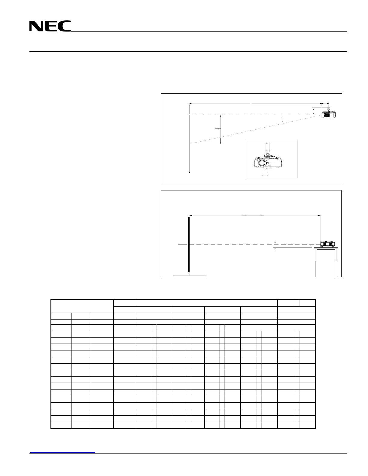
Projection Distance and Screen Size for Ceiling Mount
The following shows the proper relative positions of the projector and screen. Refer to the table to determine the position of
installation.
Distances are in inches. For millimeters multiply by 25.4.
Ceiling Mount Installation
Desktop Installation
Note:
Lens shift feature is not available with NP10FL
(rear lens) NP10FL should be used only for
“zero degree” / “no-offset” applications.
Distance Chart for popular 4:3 screens
Screen Size (4:3)
Diagonal Width(H) Height (V) 0.8:1
inches inches inches inches
40 32 24 25.38 47.37 - 63.8 37.3 - 49.07 61.4 98.6
60 48 36 38.7 72.11 - 96.6 56.9 - 74.5 93.5 - 149.4 141.7 229.7 NA NA
67 53.6 40.2 43.3 80.8 - 108.2 63.7 - 83.4 104.7 - 167.1 158.8 257.0 NA NA
72 57.6 43.2 46.6 86.9 - 116.4 68.6 - 89.8 112.8 - 179.8 171.1 276.6 260.7 415.0
84 67.2 50.4 54.6 101.8 - 136.1 80.3 - 105.0 132.0 - 210.3 200.4 - 323.5 316.8 - 485.5
90 72 54 58.6 109.2 - 146.0 86.2 - 112.6 141.7 - 225.5 215.0 - 346.9 340.0 - 520.7
100 80 60 65.2 121.6 - 162.4 95.96 - 125.4 157.7 - 250.8 239.5 - 386.0 378.6 - 579.4
120 96 72 78.5 146.3 - 195.3 115.5 - 150.8 189.8 - 301.6 288.3 - 464.2 455.8 - 696.8
150 120 90 98.46 183.4 - 244.6 144.8 - 188.9 238.0 - 377.7 361.6 - 581.5 571.7 - 872.9
180 144 108 NA 220.5 - 294.0 174.2 - 227.1 286.2 - 453.8 434.9 - 698.7 687.5 - 1049.0
210 168 126 NA 257.6 - 343.3 203.5 - 265.2 334.3 - 529.9 508.2 - 816.0 803.4 - 1225.1
240 192 144 NA 294.7 - 392.6 232.8 - 303.4 382.5 - 606.0 581.5 - 933.3 919.3 - 1401.2
270 216 162 NA 331.8 - 442.0 262.2 - 341.5 430.7 - 682.1 654.8 - 1050.5 1035.1 - 1577.3
300 240 180 NA 368.9 - 491.3 291.5 - 379.7 478.8 - 758.2 728.1 - 1167.8 1151.0 - 1753.5
400 320 240 NA 492.6 - 655.7 389.2 - 506.8 639.4 - 1011.9 972.4 - 1558.7 1537.2 - 2340.5
500 400 300 NA 616.30 - 820.2 487.0 - 634.0 799.9 1265.6 1216.7 - 1949.6 1923.4 - 2927.5
Note:
For screen sizes not indicated on the projection tables, use the formulas on page 1.
Rear Lens
NP01FL
Standard NP02ZL NP03ZL NP04ZL
1.5 - 2.0:1 1.18 - 1.54:1
Screen Ctr
es
Screen Ctr
Screen Top
Shift Range
Screen Bottom
Zoom Lenses
1.94 - 3.07:1
C
Throw Distance
C
Throw Distance
2.98 - 4.77:1
NA
3.30"
es
X=Distance from lens to mount ctr
Lens Offset From
Mount Pipe
3.45"
NP05ZL
4.62 - 7.02:1
NA
7.72"
es
X
Standard: X=7.03"
NP01FL: X=8.03"
NP02FL: X=7.78"
NP03FL: X=7.83"
NP04FL: X=7.44"
NP05FL: X=7.41"
www.necvisualsystems.com NP1000/2000 Page 2 of 9

NEC Solutions (America), Inc.
Visual Systems Division
NP1000/2000 Installation Guide
Desktop and Ceiling Mount v 1.1
Projection Distance and Screen Size for Ceiling Mount
The following shows the proper relative positions of the projector and screen. Refer to the table to determine the position of
installation.
Distances are in inches. For millimeters multiply by 25.4.
Ceiling Mount Installation
Screen Top
Shift Range
Screen Ctr
Desktop Installation
Note:
Lens shift feature is not available with NP10FL
(rear lens) NP10FL should be used only for
“zero degree” / “no-offset” applications.
Screen Ctr
Screen Bottom
Distance Chart for popular 16:9 screens
Screen Size (16:9)
Di agonal Width(H) Height (V) 0.8:1
inches inches inches inches
92 80 45 65.24 121.6 - 162.4 96.0 - 125.4 157.7 250.8 239.5 386.0 366.4 579.4
100 87 49 71.1 132.4 - 176.8 104.5 - 136.5 171.8 - 273.0 260.8 420.2 399.5 630.8
106 92 52 75.2 140.1 - 187.1 110.6 - 144.4 181.8 - 288.9 276.1 444.7 423.1 667.4
110 96 54 78.5 146.3 - 195.3 115.5 - 150.8 189.8 - 301.6 288.3 464.2 442.0 696.8
119 104 58.8 85.2 158.7 - 211.8 125.3 - 163.5 205.9 - 326.9 312.8 - 503.3 494.4 - 755.5
123 107 60 87.7 163.3 - 217.9 129.0 - 168.3 211.9 - 336.5 321.9 - 518.0 508.9 - 777.5
133 116 65 95.1 177.2 - 236.4 140.0 - 182.6 230.0 - 365.0 349.4 - 561.9 552.4 - 843.6
135 118 66 96.8 180.3 - 240.5 142.4 - 185.8 234.0 - 371.3 355.5 - 571.7 562.0 - 858.2
159 139 78 NA 212.8 - 283.7 168.1 - 219.1 276.1 - 437.9 419.6 - 674.3 663.4 - 1012.3
161 140 79 NA 214.3 - 285.8 169.3 - 220.7 278.1 - 441.1 422.7 - 679.2 668.2 - 1019.7
229 200 113 NA 307.1 - 409.1 242.6 - 316.1 398.6 - 631.4 605.9 - 972.4 957.9 - 1459.9
275 240 135 NA 368.9 - 491.3 291.5 - 379.7 478.8 - 758.2 728.1 - 1167.8 1151.0 - 1753.5
367 320 180 NA 492.6 - 655.7 389.2 - 506.8 639.4 - 1011.9 972.4 - 1558.7 1537.2 - 2340.5
459 400 225 NA 616.3 - 820.2 487.0 - 634.0 799.9 - 1265.6 1216.7 - 1949.6 1923.4 - 2927.5
Note:
For screen sizes not indicated on the projection tables, use the formulas on page 1.
www.necvisualsystems.com NP1000/2000 Page 3 of 9
Rear Lens
NP01FL
Standard NP02ZL NP03ZL NP04ZL
1.5 - 2.0:1 1.18 - 1.54:1
inchesinches
Zoom Lenses
1.94 - 3.07:1
inches inches
C
Throw Distance
Lens Offset From
Mount Pipe
3.30"
C
Throw Distance
2.98 - 4.77:1
X=Distance from lens to mount ctr
3.45"
NP05ZL
4.62 - 7.02:1
inches
7.72"
Standard: X=7.03"
NP01FL: X=8.03"
NP02FL: X=7.78"
NP03FL: X=7.83"
NP04FL: X=7.44"
NP05FL: X=7.41"
X

0.50V
NEC Solutions (America), Inc.
Visual Systems Division
NP1000/2000 Installation Guide
Desktop and Ceiling Mount v 1.1
Lens Shift Adjustable Range
Desktop/Front
Vertical
Ceiling/Front
Vertical
0.10H
0.5V
Normal Position
Normal Position
0.5V
0.10H
Horizontal
Normal Position
Lens Shift Range for Desktop and Ceiling Mount
Application
The diagram below shows the location of the image position
in the lens. The lens can be shifted within the shaded area as
shown using the normal projection position as a starting
point.
Note: Lens shift feature is not available with NP10FL (rear
lens). NP10FL should be used only for “zero degree” / “nooffset” applications.
Maximum Possible Range
for Standard Lens/NP02ZL/NP03ZL/NP04ZL/NP05ZL:
Up: 0.5V
Right: 0.10H
Left: 0.10H
(H: width of projected image, V: height of projected image)
0.10H
0.10H
0.50V
Normal projection
www.necvisualsystems.com NP1000/2000 Page 4 of 9
position

NEC Solutions (America), Inc.
A
r
Visual Systems Division
NP1000/2000 Installation Guide
Desktop and Ceiling Mount v 1.1
Cabinet Dimensions
The following diagrams show the cabinet dimensions for the NP1000/2000.
Dimensions are in inches. For millimeters multiply by 25.4.
5.924
www.necvisualsystems.com NP1000/2000 Page 5 of 9
15.7
Lens Shift Control
15.7
()
4.59
.157
Air Filters
14.09
.28
.02
6.625
3.46
()
For Mount
M4*8 MAX
9.37
2.33
2.20
10.925
.157
11.20
Speakers
ir Exhaust Lamp cove

NEC Solutions (America), Inc.
Visual Systems Division
NP1000/2000 Installation Guide
Desktop and Ceiling Mount v 1.1
Lens Dimensions
The following drawings show the added dimensions for the optional lenses
Dimensions are in inches. For millimeters multiply by 25.4.
NP w Standard Lens
14.09
NP02ZL
14.09
3.81
NP04ZL
.75
14.09
3.25
.40
www.necvisualsystems.com NP1000/2000 Page 6 of 9
NP01FL
14.09
.96
3.385
NP03ZL
14.09
.80
3.385
NP05ZL
14.09
.38
3.25

NEC Solutions (America), Inc.
Visual Systems Division
NP1000/2000 Installation Guide
Desktop and Ceiling Mount v 1.1
Optional Ceiling Mount Dimensions (Model #: NP1000CM)
The following diagrams show ceiling mount dimensions for the NP1000/2000.
Dimensions are in inches. For millimeters multiply by 25.4.
10.41
15.19
12.11
4.95
9.99
5.88
Pole Ceiling Mount with Input Cover
5.02 10.17
www.necvisualsystems.com NP1000/2000 Page 7 of 9

NEC Solutions (America), Inc.
Visual Systems Division
NP1000/2000 Installation Guide
Desktop and Ceiling Mount v 1.1
Optional Ceiling Mount Dimensions (Model #: NP1000CM) (continued)
The following diagrams show ceiling mount dimensions for the NP1000/2000.
Dimensions are in inches. For millimeters multiply by 25.4.
12.11
POLE MOUNT W/O I/O COVER
www.necvisualsystems.com NP1000/2000 Page 8 of 9
10.75
4.95
5.02
5.73

NEC Solutions (America), Inc.
Visual Systems Division
NP1000/2000 Installation Guide
Desktop and Ceiling Mount v 1.1
PC Control Codes
Function Code Data
POWER ON 02H 00H 00H 00H 00H 02H
POWER OFF 02H 01H 00H 00H 00H 03H
INPUT SELECT RGB 1 02H 03H 00H 00H 02H 01H 01H 09H
INPUT SELECT RGB 2 02H 03H 00H 00H 02H 01H 02H 0AH
INPUT SELECT RGB 3 02H 03H 00H 00H 02H 01H 1AH 22H
INPUT SELECT COMPONENT 02H 03H 00H 00H 02H 01H 10H 18H
INPUT SELECT VIDEO 02H 03H 00H 00H 02H 01H 06H 0EH
INPUT SELECT S-VIDEO 02H 03H 00H 00H 02H 01H 0BH 13H
INPUT SELECT PC CARD VIEWER 02H 03H 00H 00H 02H 01H 1FH 27H
INPUT SELECT LAN 02H 03H 00H 00H 02H 01H 20H 28H
PICTURE MUTE ON 02H 10H 00H 00H 00H 12H
PICTURE MUTE OFF 02H 11H 00H 00H 00H 13H
SOUND MUTE ON 02H 12H 00H 00H 00H 14H
SOUND MUTE OFF 02H 13H 00H 00H 00H 15H
ON SCREEN MUTE ON 02H 14H 00H 00H 00H 16H
ON SCREEN MUTE OFF 02H 15H 00H 00H 00H 17H
Cable Connection
Communication Protocol:
Baud Rate: 38400 bps (for cable lengths longer than 20’, it is recommended changing to 9600 bps in setup menu)
Data Length: 8 bits
Parity: No Parity
Stop Bit: One bit
X on/off: None
Communications: Full duplex
12
34
5
67 8
9
PC Control Connector (D-Sub 9P)
NOTE: Pins 1, 4, 6, and 9 are used inside the projector.
Jumper “Request to send” and “Clear to Send” together on both ends of the cable to simplify cable connection.
To TxD of PC
To RxD of PC
To GND of PC
To RTS of PC
To CTS of PC
www.necvisualsystems.com NP1000/2000 Page 9 of 9
 Loading...