

Page 1
ND-70923 (E)
STOCK # 151992
®
Q-SIG System Manual
ISSUE 1
JULY, 2000
NEC America, Inc.
Page 2

LIABILITY DISCLAIMER
NEC America, Inc. reserves the right to change the specifications,
functions, or features, at any time, without notice.
NEC America, Inc. has prepared this document for use by its
employees and custome rs. The information contained herein is
the property of NEC America, Inc. and shall not be reproduced
without prior written approval from NEC America, Inc.
NEAX and D
term
are registered trademarks of NEC Corporation.
Copyright 2000
NEC America, Inc.
Printed in U.S.A.
Page 3

PAGE No.
i 1
ii 1
iii 1
iv
1 1
2 1
3 1
4
5 1
6 1
7 1
8
9 1
10 1
11 1
12
13 1
14 1
15 1
16
17 1
18 1
19 1
20
21 1
22 1
23 1
24
25 1
26 1
27 1
28
29 1
30 1
31 1
32
33 1
34 1
DATE JU LY, 20 00 DATE DATE DATE
DA TE DATE DA TE DA TE
NEAX2000 IVS
12345678
1
1
1
1
1
1
1
1
1
ISSUE 1 ISSUE 2 ISSUE 3 ISSUE 4
ISSUE 5 ISSUE 6 ISSUE 7 ISSUE 8
2
ISSUE No.
PAGE No.
35 1
36
37 1
38 1
39 1
40
41 1
42 1
43 1
44
45 1
46 1
47 1
48
49 1
50 1
51 1
52
53 1
54 1
55 1
56
57 1
58 1
59 1
60
61 1
62 1
63 1
64
65 1
66 1
67 1
68
12345678
1
1
1
1
1
1
1
1
1
Q-SIG System Manual
ISSUE No.
Revision Sheet 1/1
ND-70923 (E)
Page 4

NEAX2000 IVS
2
Q-SIG System Manual
TABLE OF CONTENTS
Page
LIST OF FIGURES . . . . . . . . . . . . . . . . . . . . . . . . . . . . . . . . . . . . . . . . . . . . . . . . . . . . . . . . iii
LIST OF TABLES . . . . . . . . . . . . . . . . . . . . . . . . . . . . . . . . . . . . . . . . . . . . . . . . . . . . . . . . . iv
INTRODUCTION . . . . . . . . . . . . . . . . . . . . . . . . . . . . . . . . . . . . . . . . . . . . . . . . . . . . . . . . . 1
PURPOSE . . . . . . . . . . . . . . . . . . . . . . . . . . . . . . . . . . . . . . . . . . . . . . . . . . . . . . . . . . . . . . . . . . 1
OUTLINE OF THIS MANUAL. . . . . . . . . . . . . . . . . . . . . . . . . . . . . . . . . . . . . . . . . . . . . . . . . . . . 1
REFERENCE MANUALS. . . . . . . . . . . . . . . . . . . . . . . . . . . . . . . . . . . . . . . . . . . . . . . . . . . . . . . 2
CHAPTER 1 GENERAL INFORMATION . . . . . . . . . . . . . . . . . . . . . . . . . . . . . . . . . . . . . 3
SYSTEM OUTLINE . . . . . . . . . . . . . . . . . . . . . . . . . . . . . . . . . . . . . . . . . . . . . . . . . . . . . . . . . . . 4
Summary . . . . . . . . . . . . . . . . . . . . . . . . . . . . . . . . . . . . . . . . . . . . . . . . . . . . . . . . . . . . . . . . 4
Physical Interface 30DTI . . . . . . . . . . . . . . . . . . . . . . . . . . . . . . . . . . . . . . . . . . . . . . . . . . . . 5
Physical Interface 24DTI . . . . . . . . . . . . . . . . . . . . . . . . . . . . . . . . . . . . . . . . . . . . . . . . . . . . 5
Interworking with Other Network . . . . . . . . . . . . . . . . . . . . . . . . . . . . . . . . . . . . . . . . . . . . . . 6
SYSTEM CONFIGURATION . . . . . . . . . . . . . . . . . . . . . . . . . . . . . . . . . . . . . . . . . . . . . . . . . . . . 7
30DTI . . . . . . . . . . . . . . . . . . . . . . . . . . . . . . . . . . . . . . . . . . . . . . . . . . . . . . . . . . . . . . . . . . . 8
DCH . . . . . . . . . . . . . . . . . . . . . . . . . . . . . . . . . . . . . . . . . . . . . . . . . . . . . . . . . . . . . . . . . . . . 8
24DTI . . . . . . . . . . . . . . . . . . . . . . . . . . . . . . . . . . . . . . . . . . . . . . . . . . . . . . . . . . . . . . . . . . . 8
DCH . . . . . . . . . . . . . . . . . . . . . . . . . . . . . . . . . . . . . . . . . . . . . . . . . . . . . . . . . . . . . . . . . . . . 8
PLO . . . . . . . . . . . . . . . . . . . . . . . . . . . . . . . . . . . . . . . . . . . . . . . . . . . . . . . . . . . . . . . . . . . . 9
CARD NAME AND FUNCTION . . . . . . . . . . . . . . . . . . . . . . . . . . . . . . . . . . . . . . . . . . . . . . . . . . 10
SYSTEM CAPACITY . . . . . . . . . . . . . . . . . . . . . . . . . . . . . . . . . . . . . . . . . . . . . . . . . . . . . . . . . . 11
SYSTEM CONDITIONS . . . . . . . . . . . . . . . . . . . . . . . . . . . . . . . . . . . . . . . . . . . . . . . . . . . . . . . . 12
Time Slot Assignment Condition . . . . . . . . . . . . . . . . . . . . . . . . . . . . . . . . . . . . . . . . . . . . . . 12
Time Slot Allocation for DTI/DCH Card . . . . . . . . . . . . . . . . . . . . . . . . . . . . . . . . . . . . . . . . . 13
SERVICE FEATURES . . . . . . . . . . . . . . . . . . . . . . . . . . . . . . . . . . . . . . . . . . . . . . . . . . . . . . . . . 14
Connected Destination Indication . . . . . . . . . . . . . . . . . . . . . . . . . . . . . . . . . . . . . . . . . . . . . 14
Transit Counter Relaying . . . . . . . . . . . . . . . . . . . . . . . . . . . . . . . . . . . . . . . . . . . . . . . . . . . . 16
CHAPTER 2 INSTALLATION . . . . . . . . . . . . . . . . . . . . . . . . . . . . . . . . . . . . . . . . . . . . . . 17
PRECAUTIONS . . . . . . . . . . . . . . . . . . . . . . . . . . . . . . . . . . . . . . . . . . . . . . . . . . . . . . . . . . . . . . 18
STATIC ELECTRICITY GUARD . . . . . . . . . . . . . . . . . . . . . . . . . . . . . . . . . . . . . . . . . . . . . . 18
REQUIRED EQUIPMENT . . . . . . . . . . . . . . . . . . . . . . . . . . . . . . . . . . . . . . . . . . . . . . . . . . . . . . 21
INSTALLATION PROCEDURE . . . . . . . . . . . . . . . . . . . . . . . . . . . . . . . . . . . . . . . . . . . . . . . . . . 22
Mounting DTI and DCH Card . . . . . . . . . . . . . . . . . . . . . . . . . . . . . . . . . . . . . . . . . . . . . . . . . 23
MOUNTING CONN CARD . . . . . . . . . . . . . . . . . . . . . . . . . . . . . . . . . . . . . . . . . . . . . . . . . . 24
SELECTION OF PLO IN MP CARD . . . . . . . . . . . . . . . . . . . . . . . . . . . . . . . . . . . . . . . . . . . 25
DTI CABLE CONNECTION VIA MDF . . . . . . . . . . . . . . . . . . . . . . . . . . . . . . . . . . . . . . . . . . 26
DTI CABLE CONNECTION VIA CONN CARD . . . . . . . . . . . . . . . . . . . . . . . . . . . . . . . . . . . 29
NEAX2000 IVS2 Q-SIG System Manual
ND-70923 (E), Issue 1.0
Page i
Page 5

TABLE OF CONTENTS
Page
CHAPTER 3 SYSTEM DATA PROGRAMMING . . . . . . . . . . . . . . . . . . . . . . . . . . . . . . . . 31
HOW TO READ THIS CHAPTER. . . . . . . . . . . . . . . . . . . . . . . . . . . . . . . . . . . . . . . . . . . . . . . . . 32
DTI ASSIGNMENT. . . . . . . . . . . . . . . . . . . . . . . . . . . . . . . . . . . . . . . . . . . . . . . . . . . . . . . . . . . . 33
DCH ASSIGNMENT. . . . . . . . . . . . . . . . . . . . . . . . . . . . . . . . . . . . . . . . . . . . . . . . . . . . . . . . . . . 37
TANDEM CONNECTION ASSIGNMENT. . . . . . . . . . . . . . . . . . . . . . . . . . . . . . . . . . . . . . . . . . . 38
CONNECTED DESTINATION INDICATION ASSIGNMENT. . . . . . . . . . . . . . . . . . . . . . . . . . . . 39
CHAPTER 4 CIRCUIT CARD INFORMATION . . . . . . . . . . . . . . . . . . . . . . . . . . . . . . . . . 41
HOW TO READ THIS CHAPTER. . . . . . . . . . . . . . . . . . . . . . . . . . . . . . . . . . . . . . . . . . . . . . . . . 42
MOUNTING LOCATION OF CIRCUIT CARD . . . . . . . . . . . . . . . . . . . . . . . . . . . . . . . . . . . . . . . 43
LIST OF REQUIRED CIRCUIT CARD . . . . . . . . . . . . . . . . . . . . . . . . . . . . . . . . . . . . . . . . . . . . . 44
PN-CP14 (MP) . . . . . . . . . . . . . . . . . . . . . . . . . . . . . . . . . . . . . . . . . . . . . . . . . . . . . . . . . . . . 45
PN-30DTC-A (DTI) . . . . . . . . . . . . . . . . . . . . . . . . . . . . . . . . . . . . . . . . . . . . . . . . . . . . . . . . 50
PN-24DTA-C (DTI) . . . . . . . . . . . . . . . . . . . . . . . . . . . . . . . . . . . . . . . . . . . . . . . . . . . . . . . . 56
PN-SC01 (DCH) . . . . . . . . . . . . . . . . . . . . . . . . . . . . . . . . . . . . . . . . . . . . . . . . . . . . . . . . . . 62
PZ-M542 (CONN) . . . . . . . . . . . . . . . . . . . . . . . . . . . . . . . . . . . . . . . . . . . . . . . . . . . . . . . . . 65
PZ-M557 (CONN) . . . . . . . . . . . . . . . . . . . . . . . . . . . . . . . . . . . . . . . . . . . . . . . . . . . . . . . . . 67
Page ii ND-70923 (E), Issue 1.0
NEAX2000 IVS2 Q-SIG System Manual
Page 6

LIST OF FIGURES
Figure Title Page
Figure 1-1 System Outline of Q-SIG . . . . . . . . . . . . . . . . . . . . . . . . . . . . . . . . . . . . . . . . . . . . . . . 4
Figure 1-2 Physical Interface . . . . . . . . . . . . . . . . . . . . . . . . . . . . . . . . . . . . . . . . . . . . . . . . . . . . 5
Figure 1-3 Physical Interface . . . . . . . . . . . . . . . . . . . . . . . . . . . . . . . . . . . . . . . . . . . . . . . . . . . . 5
Figure 1-4 Interworking with Other Network . . . . . . . . . . . . . . . . . . . . . . . . . . . . . . . . . . . . . . . . . 6
Figure 1-5 System Configuration of Q-SIG . . . . . . . . . . . . . . . . . . . . . . . . . . . . . . . . . . . . . . . . . . 7
Figure 1-6 Clock Supply Route Configuration . . . . . . . . . . . . . . . . . . . . . . . . . . . . . . . . . . . . . . . . 9
Figure 1-7 Accommodation of DTI/DCH/ICH/BRT/PRT into TDSW . . . . . . . . . . . . . . . . . . . . . . . 12
Figure 1-8 Time Slot Allocation for DTI . . . . . . . . . . . . . . . . . . . . . . . . . . . . . . . . . . . . . . . . . . . . . 13
Figure 1-9 Connected Destination Indication . . . . . . . . . . . . . . . . . . . . . . . . . . . . . . . . . . . . . . . . 14
Figure 1-10 Transit Counter . . . . . . . . . . . . . . . . . . . . . . . . . . . . . . . . . . . . . . . . . . . . . . . . . . . . . . 16
Figure 2-1 Static Electricity Guard (1 of 2) . . . . . . . . . . . . . . . . . . . . . . . . . . . . . . . . . . . . . . . . . . 18
Figure 2-2 Installation Procedure for Q-SIG . . . . . . . . . . . . . . . . . . . . . . . . . . . . . . . . . . . . . . . . . 22
Figure 2-3 Cable Connection via MDF . . . . . . . . . . . . . . . . . . . . . . . . . . . . . . . . . . . . . . . . . . . . . 26
Figure 2-4 Location of the AP Slots and the LTC Connectors for DTI . . . . . . . . . . . . . . . . . . . . . 27
Figure 2-5 Example of MDF Cross Connection for DTI . . . . . . . . . . . . . . . . . . . . . . . . . . . . . . . . 28
Figure 2-6 Cable Connection via the CONN Card . . . . . . . . . . . . . . . . . . . . . . . . . . . . . . . . . . . . 29
Figure 2-7 Example of Coaxial Cable Connection . . . . . . . . . . . . . . . . . . . . . . . . . . . . . . . . . . . . 30
Figure 4-1 Mounting Location of Circuit Card . . . . . . . . . . . . . . . . . . . . . . . . . . . . . . . . . . . . . . . . 43
NEAX2000 IVS2 Q-SIG System Manual
ND-70923 (E), Issue 1.0
Page iii
Page 7

LIST OF TABLES
Table Title Page
Table 1-1 Q-SIG Card Name and Function . . . . . . . . . . . . . . . . . . . . . . . . . . . . . . . . . . . . . . . . . 10
Table 1-2 System Capacity for Q-SIG . . . . . . . . . . . . . . . . . . . . . . . . . . . . . . . . . . . . . . . . . . . . . 11
Table 2-1 Required Equipment for Q-SIG . . . . . . . . . . . . . . . . . . . . . . . . . . . . . . . . . . . . . . . . . . 21
Table 4-1 List of Required Circuit Card . . . . . . . . . . . . . . . . . . . . . . . . . . . . . . . . . . . . . . . . . . . . 44
Page iv ND-70923 (E), Issue 1.0
NEAX2000 IVS2 Q-SIG System Manual
Page 8

INTRODUCTION
Purpose
INTRODUCTION
PURPOSE
This manual describes the hardware installation and programming procedure for the Q-SIG
System on the NEAX2000 IVS2.
OUTLINE OF THIS MANUAL
This manual consists of the following chapters:
CHAPTER 1 GENERAL INFORMATION
This chapter explains the Q-SIG system outline, system configuration, the name and functions
of circuit cards required, system capacity, system conditions, and available service features.
CHAPTER 2 INSTALLATION
This chapter ex plains the hardw are installation procedure to p rovide Q-SIG inter face on the PB X.
CHAPTER 3 SYSTEM DATA PROGRAMMING
This chapter explains the programming procedure to provide Q-SIG feature on the PBX.
CHAPTER 4 CIRCUIT CARD INFORMATION
This chapter explains the mounting location, the meaning of lamp indications, and the method of
switch settings of each circuit card for the Q-SIG.
NEAX2000 IVS2 Q-SIG System Manual
ND-70923 (E), Issue 1.0 Pa ge 1
Page 9

INTRODUCTION
Reference Manuals
REFERENCE MANUALS
Refe r to the follo wing manuals during installation:
Installation Procedure Manual: Describes the installation procedure of the PBX system.
Command Manual: Describes Customer Administration Terminal (CAT)
operation, command function and setting data required for
programming the system, and Resident System Program.
Office Data Programming Manual: Contains the Customer Specif ication Sheet and Office Data
Programming Sheet.
Page 2 ND-70923 (E), Issue 1.0
NEAX2000 IVS2 Q-SIG System Manual
Page 10

CHAPTER 1
GENERAL INFORMATION
This chapter explains the Q-SIG system outline, system configuration,
the name and functions of circuit cards required, system capacity,
system conditions, and available service features.
NEAX2000 IVS2 Q-SIG System Manual
ND-70923 (E), Issue 1.0
Page 3
Page 11
CHAPTER 1 GENERAL INFORMATION
System Outline
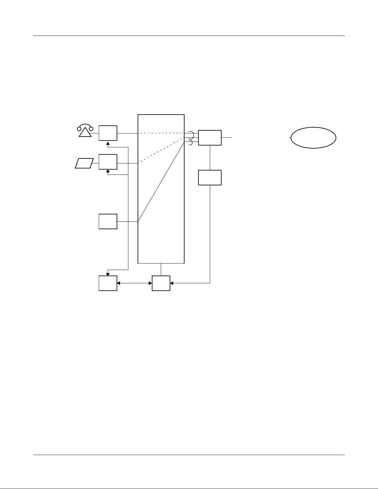
SYSTEM OUTLINE
Summary
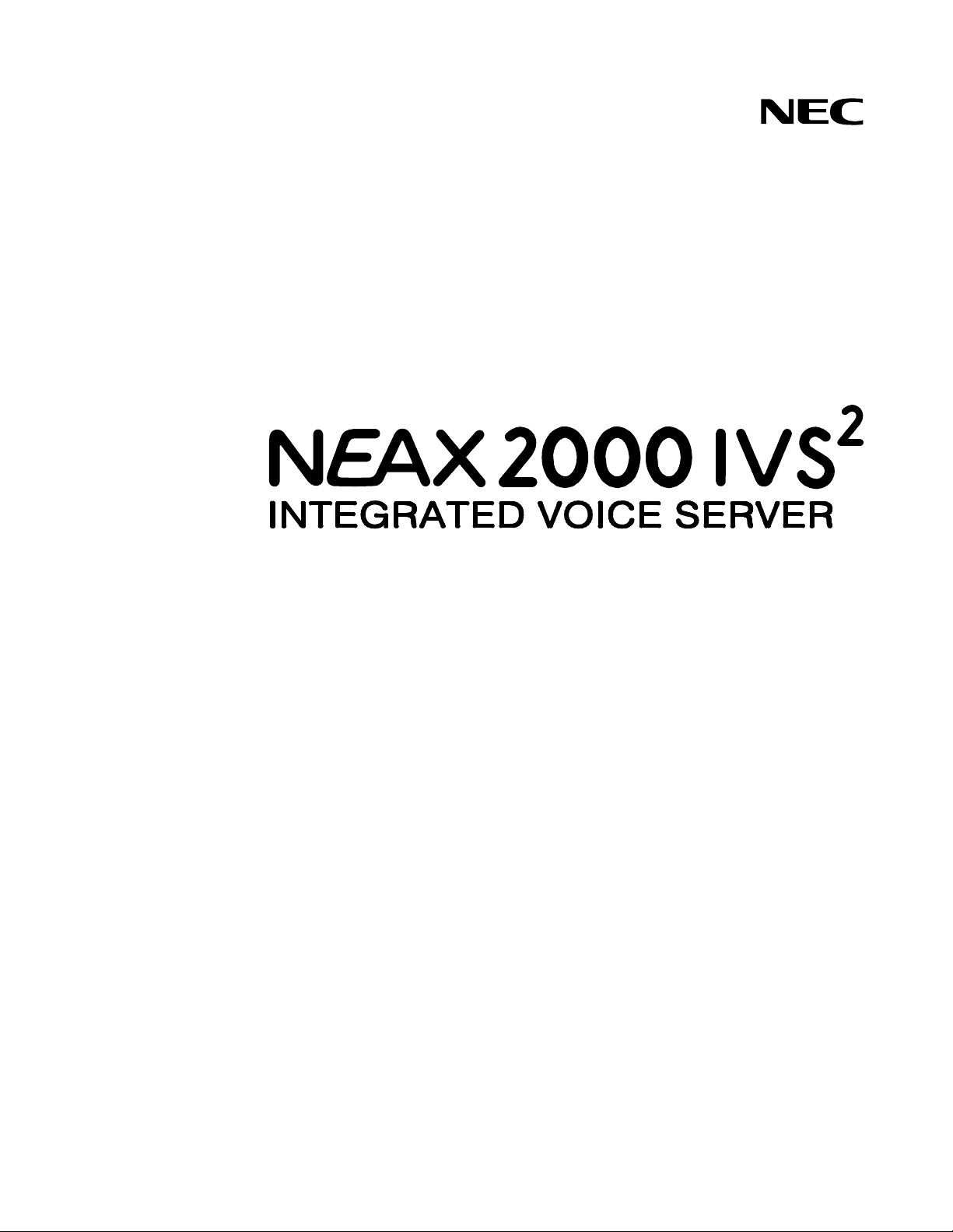
This feature allows th e PBX to provide basic conne ction service for interfaci ng with the other PBX
by using Layer 3 protocol which conforms to ETS 300 172. ETS 300 172 is standardized for
private telecommunication network as Inter-exchange signaling protocol for circuit mode basic
services by European Telecommunication Standards Institute (ETSI). The Q-SIG protocol
creates Layer 3 messages between Q reference points expected as conceptual point for interoffice signalling.
Figure 1-1 System Outline of Q-SIG
PBX
Call
Control
Protocol
Control
Data Link
Layer
Physical
Layer
DTI
Q-reference point
Q
Layer 2
Layer 3
NOTE
Layer 1
NOTE: Conforming to Q921-a (PBX-PBX Interface)
PBX
Call
Control
Q
DTI
Protocol
Control
DTI
Data Link
Layer
Physical
Layer
Page 4 ND-70923 (E), Issue 1.0
NEAX2000 IVS2 Q-SIG System Manual
Page 12
CHAPTER 1 GENERAL INFORMATION
System Outline
Physical Interface 30DTI
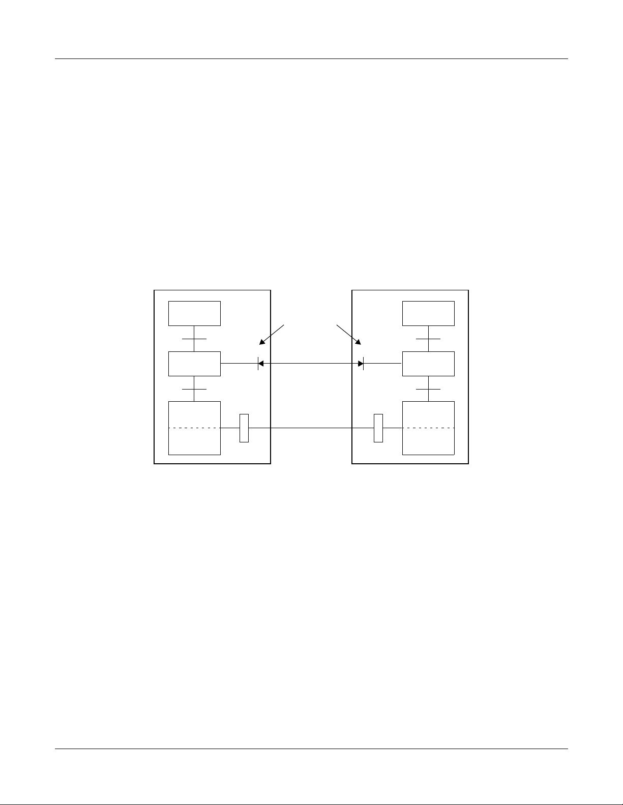
On the Q-SIG system, a 2 Mbps digital interface is used for the interf ace trunk.
A D Channel Handler is required for each physical interface. A single data link channel can
control a maximum of 30 B Channels.
Figure 1-2 Physical Interface
Physical Interface
PBX
DTI
DTI
Physical Interface
Max. 30B + D
Max. 30B + D
: D Channel
: B Channel
Physical Interface 24DTI
On the Q-SIG system, a 1.544 Mbps digital interface is used for the interface trunk.
A D Channel Handler is required for each physical interface. A single data link channel can
control a maximum of 23 B Channels.
Figure 1-3 Physical Interface
Physical Interface
PBX
DTI
DTI
Physical Interface
NEAX2000 IVS2 Q-SIG System Manual
ND-70923 (E), Issue 1.0
Max. 23B + D
Max. 23B + D
: D Channel
: B Channel
Page 5
Page 13
CHAPTER 1 GENERAL INFORMATION
System Outline
Interworking with Other Network
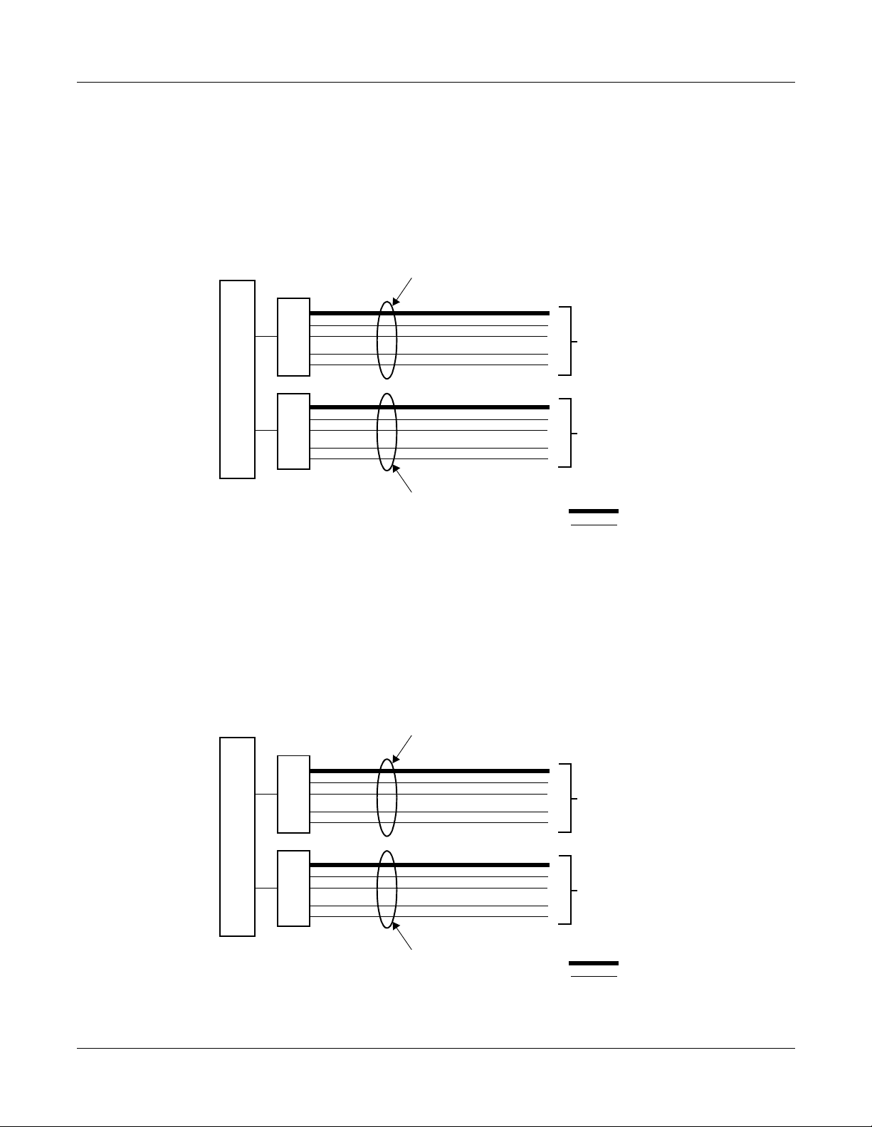
The PBX can be connect ed with t he othe r manuf actu rer’s PB X by the Q- SIG inte rfa ce, an d the
Q-SIG network can interwork with the other network.
Figure 1-4 Interworking with Other Network
ISDN
Network
NEC
Q-SIG
Network
Q-SIG interface
Other Manufacturer
Existing Office
Existing Office
ACIS
CCIS
NOTE: Interworking between Q-SIG and CCIS is not available.
Page 6 ND-70923 (E), Issue 1.0
NEAX2000 IVS2 Q-SIG System Manual
Page 14
CHAPTER 1 GENERAL INFORMATION
SYSTEM CONFIGURATION
Figure 1-5 shows the system configuration of the Q-SIG system.
Figure 1-5 System Configuration of Q-SIG
PBX
SLT
D
LC
term
DLC
30B/23B
D
DTI
PLO
30-CHANNEL PCM/23B
DIGITAL LINE
System Configuration
Q-SIG
NETWORK
DCH
TDSW
FP MP
CLOCK
DTI: 30/24-Channel Digital Trunk Interface
DCH: D Channel Handler
PLO: Phase Locked Oscillator
NEAX2000 IVS2 Q-SIG System Manual
ND-70923 (E), Issue 1.0
Page 7
Page 15

CHAPTER 1 GENERAL INFORMATION
System Configuration
30DTI
The Digital Trunk Interface (DTI) interfaces the PBX directly to 30-channel PCM transmission
line. The 30-DTI has the following functions.
• Unipolar/Bipolar Conversion (HDB3 Format)
• Signaling Insertion/Extraction
• Alarm Detection/Insertion
• Digital PAD on Voice Signal Transmission
• Cyclic Redundancy Checking (based on ITU-T Rec. G704)
• Channel Associated Signaling (based on ITU-T Rec. Q421 Digital R2 Signaling Code)
For connection o f a 30-DTI and transmission line, either coaxial cable or twisted pair cable can
be used.
DCH
The D Channel Handler (DCH) p rovi des th e D Chan nel sig nalin g inter face th ro ugh th e DTI to a
Q-SIG network, and it is responsible for signaling between the PBX and the network under
control of the system MP.
A DCH can control a maximu m of 30 B Cha nn el s .
24DTI
The Digital Trunk Interface (DTI) interfaces the PBX directly to 24-channel PCM transmission
line. The 24-DTI has the following functions.
• Unipolar/Bipolar Conversion (AMI Format)
• Alarm Detection/Insertion
• Digital PAD on Voice Signal Transmission
• Cyclic Redundancy Checking (based on ITU-T Rec. G704)
For connection of a 24-DTI and transmis s ion line, a twisted pair cable can be used.
DCH
The D Channel Handler (DCH) p rovi des th e D Chan nel sig nalin g inter face th ro ugh th e DTI to a
Q-SIG network, and it is responsible for signaling between the PBX and the network under
control of the system MP.
A DCH can control a maximu m of 23 B Cha nn el s .
Page 8 ND-70923 (E), Issue 1.0
NEAX2000 IVS2 Q-SIG System Manual
Page 16
CHAPTER 1 GENERAL INFORMATION
System Configuration
PLO
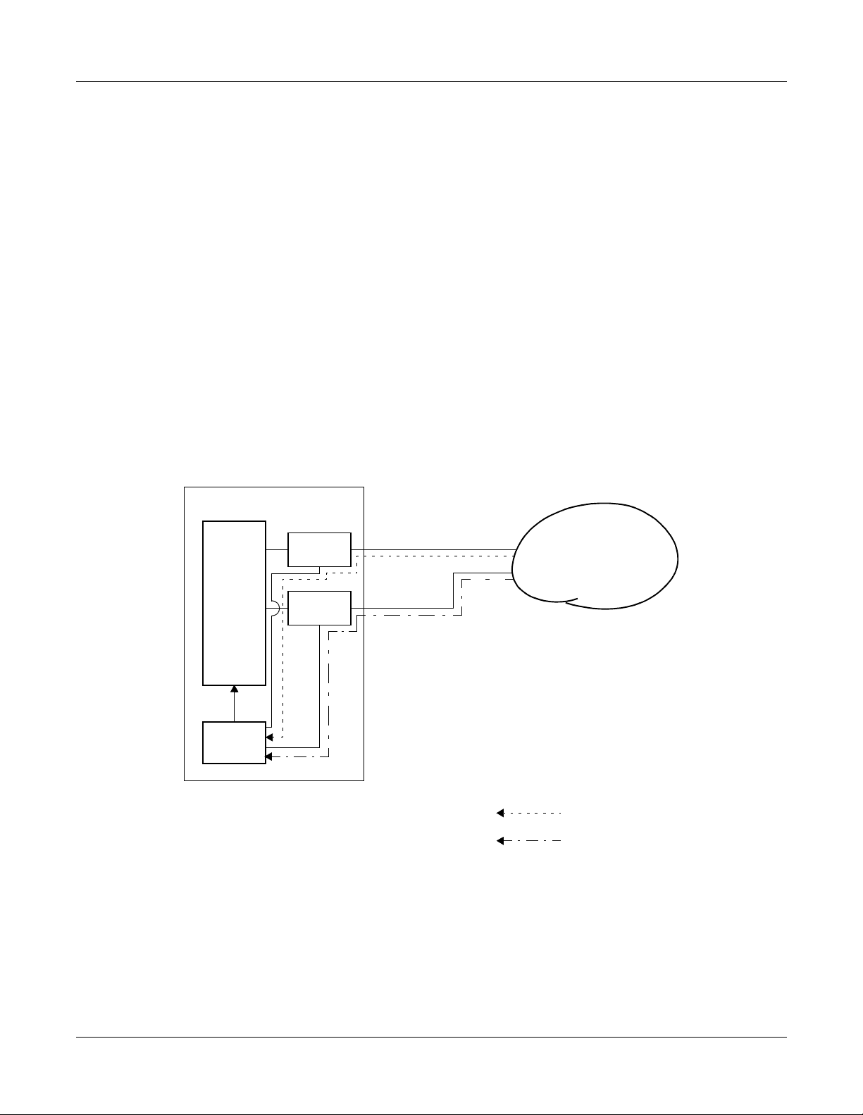
The Phase Locked Oscillator (PLO) equipped on the MP card is responsible to synchronize the
system to Q-SIG clocks.
The PLO generates the clock signals according to the source clocks received fro m network. The
source clock signals are extracted at DTI cards and supplied to the PLO. Two clock routes are
available; one is the Route 0 to receive clock sign als from DTI0, a nd the other is a standby Route
1 (DTI1) to receive clock signals when no clock signals appear on the Route 0. When clock
signals come from neither the Route 0 nor the Route 1, the PLO keeps generating the clock
signals with the frequency of previous source clock. The PLO can receive different frequency of
source clocks from the Route 0 and Route 1.
Figure 1-6 shows an example of clock supply route.
Figure 1-6 Clock Supply Route Configuration
PBX
TDSW
NOTE
DTI0
DTI1
PLO
NOTE: DTI0 and DTI1 must be mounted in PIM0.
Q-SIG
NETWORK
: CLOCK SIGNAL SUPPLY ROUTE 0
: CLOCK SIGNAL SUPPLY ROUTE 1
NEAX2000 IVS2 Q-SIG System Manual
ND-70923 (E), Issue 1.0
Page 9
Page 17

CHAPTER 1 GENERAL INFORMATION
Card Name and Function
CARD NAME AND FUNCTION
Table 1-1 shows the circuit card name and function for Q-SIG.
Table 1-1 Q-SIG Card Name and Function
FUNCTIONAL
CARD NAME
FUNCTION
NAME
PN-CP14 MP Main Processor Card
Provides Memory, TDSW (1024CH x 1024CH), 16-line
CFT, PB sender, Clock, PLO 2 ports (receiver mode/
source mo de), two RS-232C p orts, 2-line DAT
(Recording duration: Max. 128 sec.), DK, 4-line PB
receiver, Modem fo r re mo te ma i ntenance (19.2 kbps),
internal Music-on-Hold tone source and BUS interface.
BUS interface function s as a dri v er/r eceiver of various
signals, adjusts gate delay timing and cable delay timing,
monitors I/O Bus and PCM BUS.
One card is required per system.
PN-30DTC-A DTI Digital Trunk Interface (2 Mbps) Card
Accommodates 30-channel PCM digital lines.
PN-SC01 DCH D Channel Handler Card
Provides the D Channe l sig naling interface thr ough the
DTI to Q-SIG network.
PZ-M542
[For Other
Countries]
CONN Coaxial Cable Connection Card
Used to connect a coaxial cab le fo r the D i gital Tru nk
Interface.
Maximum of two cards can be connected to LTC
connector of each PIM.
PZ-M557
[For
Australia]
CONN Coaxial Cable Connection Card
Used to connect a coaxial cab le fo r the D i gital Tru nk
Interface.
Maximum of two cards can be connected to LTC
connector of each PIM.
PN-24DTA-C DTI Digital Trunk Interface (23B+D 1.5 Mbps) card
Accommodates 24-channel PCM digital lines.
Page 10 ND-70923 (E), Issue 1.0
NEAX2000 IVS2 Q-SIG System Manual
Page 18

CHAPTER 1 GENERAL INFORMATION
SYSTEM CAPACITY
Table 1-2 System Capacity for Q-SIG
DESCRIPTION 24DTI 30DTI
DTI Card 8 4
DCH Card 8 4
Trunks for DTI 192 124
Q-SIG Routes 8 4
Trunks per Q-SIG Route 23 30
MP (Internal PLO ) Ca r d 1 1
Port per DTI Card 24 32
System Capacity
Port per DCH Card 1 1
NEAX2000 IVS2 Q-SIG System Manual
ND-70923 (E), Issue 1.0
Page 11
Page 19
CHAPTER 1 GENERAL INFORMATION
System conditio ns
SYSTEM CONDITIONS
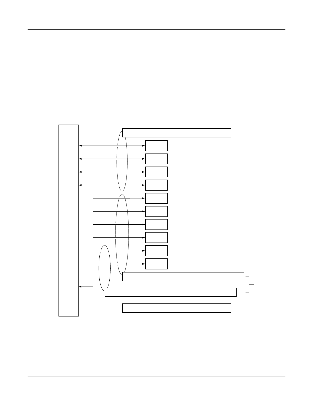
Time Slot Assignment Condition
As shown in Figure 1-7, the 30DTI/DCH card uses the time slot on the basic Highway 4.
Therefore, the total number of time slots for all 30DTI/DCH cards must be 128 time slots or less
including all other application processor cards, which use the Highway 4.
The 24DTI/PRT card can use the time slot on bo th the basic and expanded H ighw ay 4 and 6.
Figure 1-7 Accommodation of DTI/DCH/ICH/BRT/PRT into TDSW
FOR L/T CARDS: MAX. 512 TIME SLOTS PER SYSTEM
FP0
FP1
FP2
FP3
TDSW (1024 TIME SLOTS)
HW4
HW6
FOR BASIC HIGHWAY4: MAX. 128 TIME SLOTS PER SYSTEM
FOR EXPANDED HIGHWA Y6: MAX. 128 TIME SLOTS PER SYSTEM
DTI
BRT
DCH
ICH
PRT
DTI
MAX. 128 TIME SLOTS
MAX. 128 TIME SLOTS
MAX. 128 TIME SLOTS
MAX. 128 TIME SLOTS
30DTI: MAX. 31 TIME SLOTS/CARD
MAX. 2 TIME SLOTS/CARD (BRTA)
MAX. 4 TIME SLOTS/CARD (2BRTC)
1 TIME SLOT/CARD
1 TIME SLOT/CARD (SC02)
4 TIME SLOTS/CARD (SC03)
25 TIME SLOT/CARD
24DTI: MAX. 24 TIME SLOTS/CARD
FOR AP CARDS: MAX. 256 TIME SLOTS PER SYSTEM
NEAX2000 IVS2 Q-SIG System Manual
Page 12 ND-70923 (E), Issue 1.0
Page 20
CHAPTER 1 GENERAL INFORMATION
System conditions
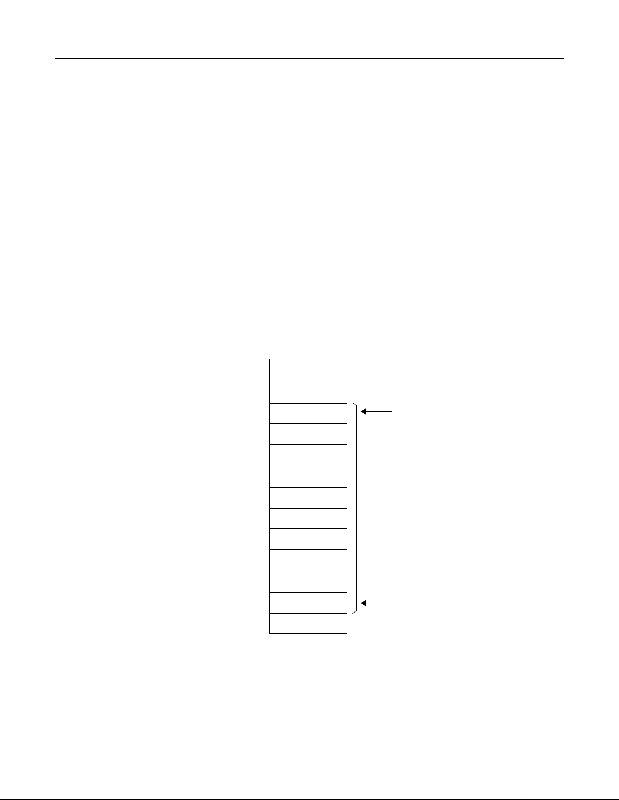
Time Slot Allocation for DTI/DCH Card
On each DTI card, the system recognizes the lowe st and highest channel numbers to which trunk
numbers have been assigned, and allocates time slots to all the channels within them. If trunk
numbers are assigned to discontinuous channels in this case, the system also allocates time
slots to channels not assigned.
For example, as shown in Figure 1-8, even wh en Channel 1 through Channel 1 0 have been
assigned by the system data programming (CM07 YY=01) excepting Channel 5, the system
allocates a total of 10 time slots for all the ten channels. Therefore, to avoid allocation of
unnecessary time slot s, it is recom mended tha t consecuti ve channe ls are a ssigned on each DTI
card.
In the case of the DCH card, one time slot is allocated for setting up a fixed path between the DTI
and the DCH by assigning Channel 16 of the DTI as the D Channel.
Figure 1-8 Time Slot Allocation for DTI
10
CH0
DXXX
9
6
5
4
1
DXXX
DXXX
NONE
DXXX
DXXX
NONE
HIGHEST CHANNEL
10 TIME SLOTS ARE
ALLOCATED E VEN
WHEN CH5 IS NOT
ASSIGNED.
LOWEST CHANNEL
NEAX2000 IVS2 Q-SIG System Manual
ND-70923 (E), Issue 1.0
Page 13
Page 21
CHAPTER 1 GENERAL INFORMATION
Service Features
SERVICE FEATURES
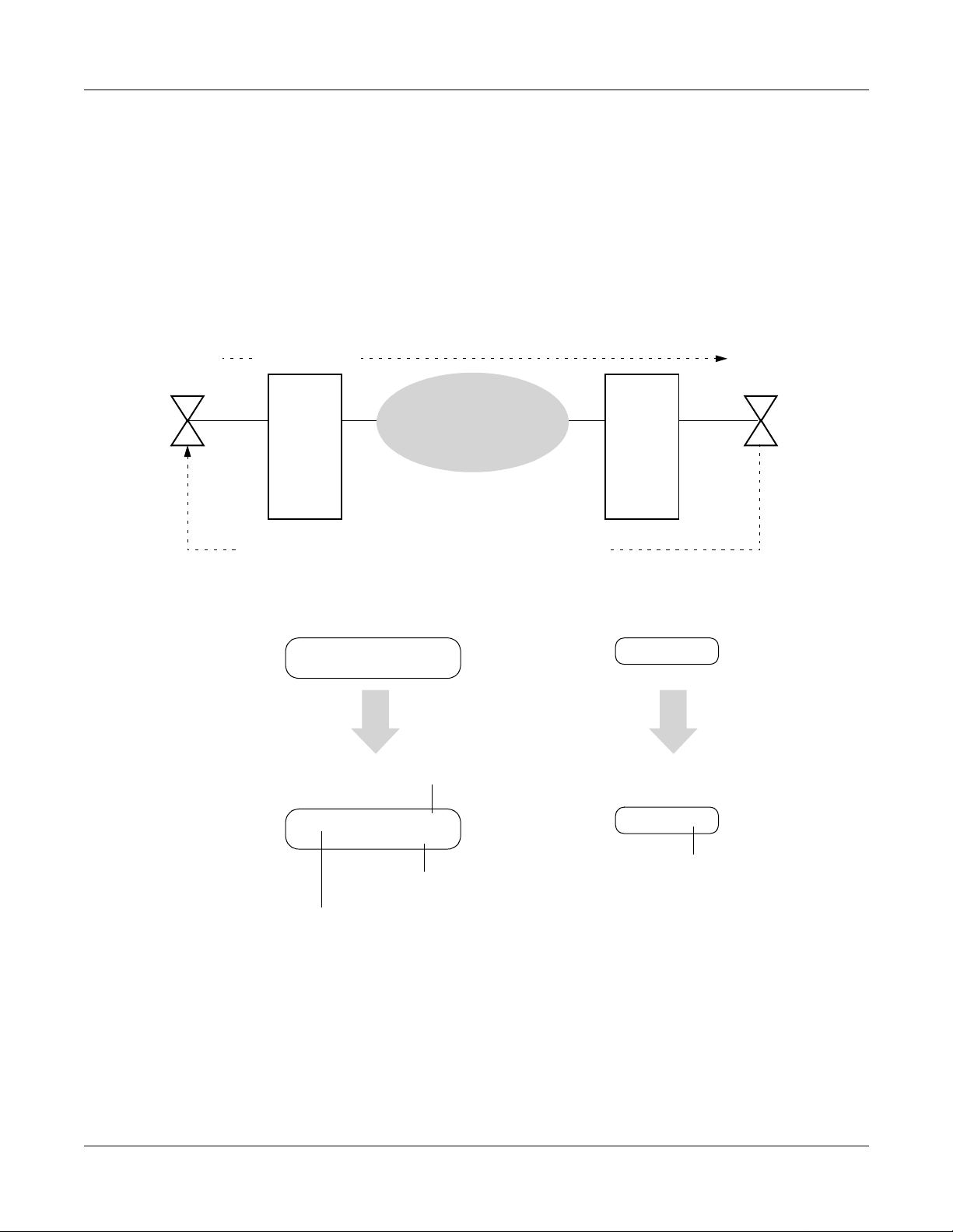
Connected Destination Indication
This feature allows the LCD on the calling station/Attendant Console to indicate the connected
destination number (answering station number) and the sub-address sent from the opposite
office.
Figure 1-9 Connected Destination Indication
STATION
No. 200
<EXAMPLE OF INDICATION>
When dialing:
DIAL “7-20-300”
OFFICE
ANSWERING STATION No. “20-300” + SUB-ADDRESS “111”
10
Q-SIG
NETWORK
term
• D
720300
2: 27 PM TUE 23
Sub-address No. (Max. 8 digits)
STATION
No. 300
OFFICE
20
• ATTCON
720300
When answered:
01: 00 111
20300
Answering station No. (Max. 8 digits)
Answering station No. (Max. 16 digits)
Duration of the call
20300
• The LCD does not indicate the answering station number and sub-address number if the
numbers are not sent from the opposite office.
• If the calling station is a n ISDN t erminal or a terminal w hich has no indicato r, the answ ering
station number and sub- address number cannot be indicated.
• If the answering station number exceed s 16 digits, the first 15 di gits and “*” are indicat ed on
term
the D
Page 14 ND-70923 (E), Issue 1.0
LCD. “*” means existence of more than 15 digits.
NEAX2000 IVS2 Q-SIG System Manual
Page 22

CHAPTER 1 GENERAL INFORMATION
Service Features
• If the sub-address exceeds 8 digits, the first 8 digits and “*” are indicated on the D
term
LCD.
“*” means existence of more than 8 digits.
• The sub-address of the answering station is not indicated on the Attendant Console LCD.
• If the answering station number exceeds 6 digits, the last 6 digits are indicated on the
Attendant Console LCD.
• It can be specified to each station (Single l in e Telephone/D
term
) whether an answering
station number is sen t or not when answering a Q-SIG call , by system data programming.
Attendant Console number cannot be sent.
NEAX2000 IVS2 Q-SIG System Manual
ND-70923 (E), Issue 1.0
Page 15
Page 23
CHAPTER 1 GENERAL INFORMATION
Service Features
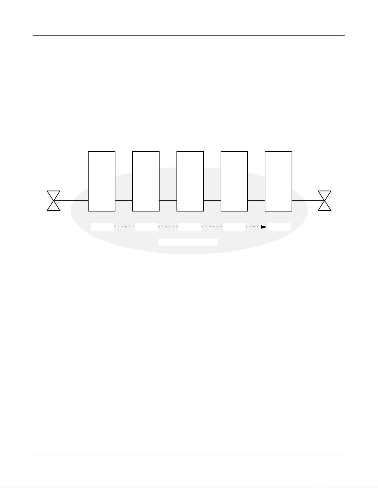
Transit Counter Relaying
Transit counter is used as the information which informs the number of stages on tandem
connection. On the Q-SIG network, the transit Counter 0 is sent from the calling office. The
tandem office sen ds the tran sit count er to th e destinatio n office adding 1 to the va lue of received
transit counter. In this manner, the transit cou nter value increases according to the numb er of the
stages of tandem connection.
Figure 1-10 Transit Counter
CALLING
OFFICE
TRC=0 TRC=1 TRC=2 TRC=3 TRC=3
TANDEM
OFFICE
TANDEM
OFFICE
Q-SIG NETWORK
TANDEM
OFFICE
DESTINATON
OFFICE
TRC: Transit Counter
• This feature is available when the all PBXs in the network are connected to each other by
Q-SIG interface.
• The transit counter values 0 thro ugh 31 are available.
• If the tandem office does not receive the transit counter from the opposite office, the tandem
office sends the transit counter as “0” to next office.
Page 16 ND-70923 (E), Issue 1.0
NEAX2000 IVS2 Q-SIG System Manual
Page 24

CHAPTER 2
INSTALLATION
This chapter explains the hardware installation procedure to provide
Q-SIG interface on the PBX.
NEAX2000 IVS2 Q-SIG System Manual
ND-70923 (E), Issue 1.0
Page 17
Page 25

CHAPTER 2 INSTALLATION
Precautions
PRECAUTIONS
STATIC ELECTRICITY GUARD
You must wear a grounded wrist strap to protect circuit cards from static electricity.
Figure 2-1 Static Electricity Guard (1 of 2)
• WHEN PLUGGING/UNPLUGGING A CIRCUIT CARD
PBX
WRIST STRAP
• WHEN HOLDING A CIRCUIT CARD
FRAME GROUND SCREW
NEVER TOUCH THE COMPONENTS OR
SOLDERED SURFACE WITH BARE HANDS.
CARD FRONT
Page 18 ND-70923 (E), Issue 1.0
NEAX2000 IVS2 Q-SIG System Manual
Page 26

Figure 2-1 Static Electricity Guard (2 of 2)
• WHEN MAKING A SWITCH SETTING ON A CIRCUIT CARD
CIRCUIT
CARD
WEAR A WRIST STRAP AND PERFORM
THE WORK ON A GROUNDED
CONDUCTIVE WORK SURFACE.
• WHEN CARRYING A CIRCUIT CARD
CHAPTER 2 INSTALLATION
Precautions
CIRCUIT
CARD
CONDUCTIVE
POLYETHYLENE
BAG
WHEN CARRYING A CIRCUIT
CARD AROUND, KEEP THE
CARD IN A CONDUCTIVE
POLYETHYLENE BAG.
The mark shown below is attached to the sheet for the work in which circuit cards are handled.
When engaging in such work, the installer must be careful not to cause damage by static
electricity.
ATTENTION
Contents
Static Sensitiv e
Handling
Precautions Required
NEAX2000 IVS2 Q-SIG System Manual
ND-70923 (E), Issue 1.0
Page 19
Page 27
CHAPTER 2 INSTALLATION
Precautions
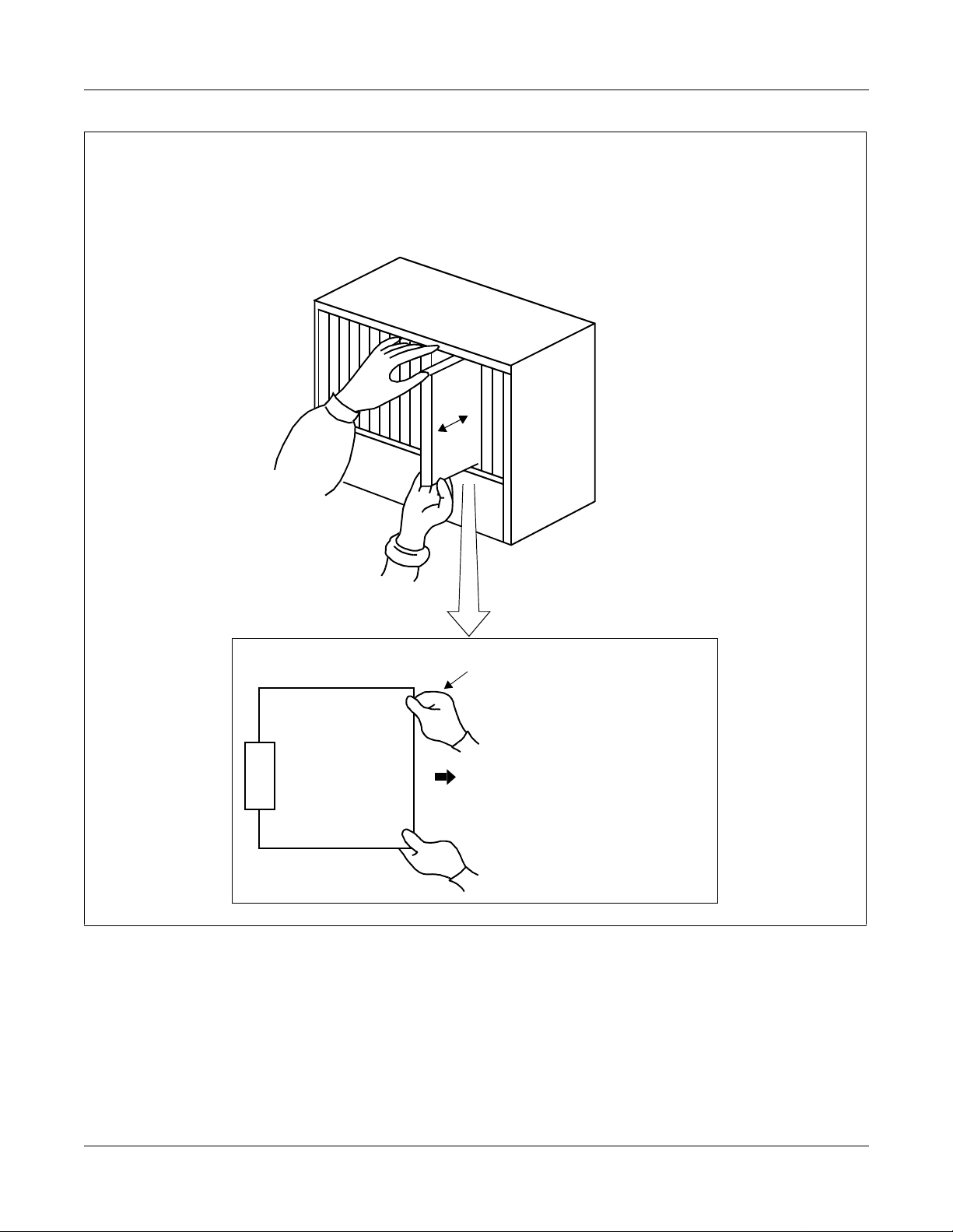
Caution
You must hold the edge of a circuit card when plugging or unplugging the circuit card. If you
touch another area, you may be exposed to hazardous voltages.
PBX
NEVER TOUCH THE
COMPONENTS OR SOLDERED
SURFACE WITH BARE HANDS.
CARD FRONT
Page 20 ND-70923 (E), Issue 1.0
NEAX2000 IVS2 Q-SIG System Manual
Page 28

CHAPTER 2 INSTALLATION
Required Equipment
REQUIRED EQUIPMENT
Table 2-1 shows the equipment required to provide Q-SIG interface to the system.
Table 2-1 Required Equipment for Q-SIG
EQUIPMENT DESCRIPTION QUANTITY REMARKS
PN-30DTC-A
30-Channel DTI Card 1-4
(30-DTI)
(Australia/Japan)
PN-24DTA-C
24-Channel DTI Card 1-4
(24-DTI)
(U.S.)
PN-SC01
D Channel Handler Card 1-4
(DCH)
PZ-M542/M557(CONN) Coaxial Cable Connection
Card
1-4 2 cards/PIM
1 DTI/card
NEAX2000 IVS2 Q-SIG System Manual
ND-70923 (E), Issue 1.0
Page 21
Page 29

CHAPTER 2 INSTALLATION
Installation Procedure
INSTALLATION PROCEDURE
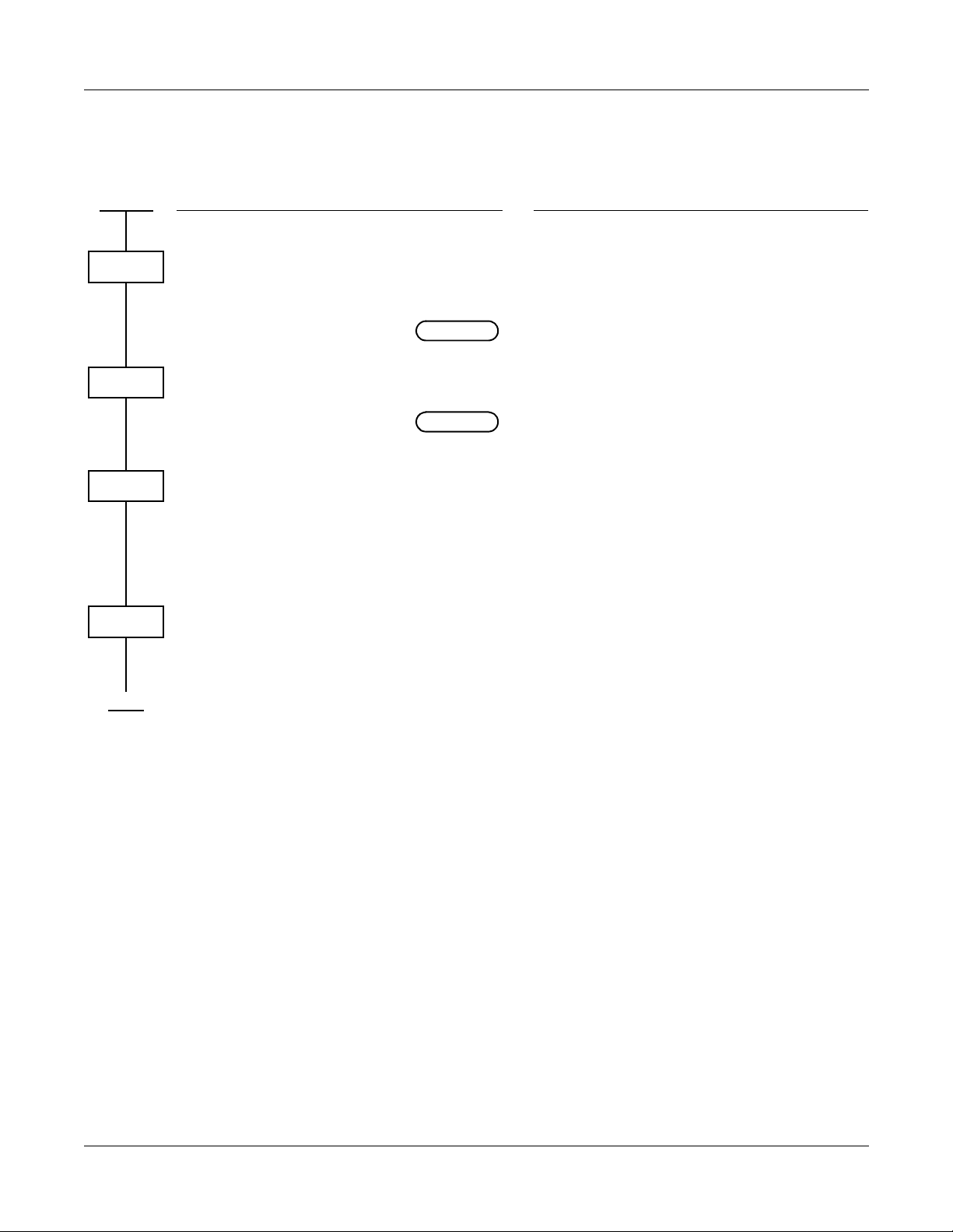
Install the equipment for Q- SIG according to the procedu re i n Figure 2-2.
Figure 2-2 Installation Procedure for Q-SIG
START
MOUNTING DTI AND
DCH CARD
MOUNTING CONN CARD
SELECTION OF PLO
IN MP CARD
DTI CABLE CONNECTION
DTI CABLE CONNECTION
VIA MDF
VIA CONN CARD
END
Page 23
Page 24
Page 25
Page 26
Page 29
NOTE
NOTE
NOTE: This procedure is requi red when you prov ide CONN card to connect a coaxia l cable
for 24-DTI/30-DTI.
Page 22 ND-70923 (E), Issue 1.0
NEAX2000 IVS2 Q-SIG System Manual
Page 30

CHAPTER 2 INSTALLATION
Installation Procedu re
Mounting DTI and DCH Card
(1) Before mounting the 24 - DTI /30 -DT I card and D C H card, set the MB
switch to UP position, and set the oth er switches to ap propria te positio n.
See CHAPTER 4, Page 41.
(2) Mount the 24-DTI/30-DTI card and the DCH card in the following AP slots
on PIM0-PIM7.
PIM0: AP00-AP10 slots
PIM1-7: AP00-AP11 slots
NOTE: The DTI card (DTI0, DTI1) which sends a clock signal to PLO of the MP card must be
mounted in the AP slots on PIM0.
(3) After mounting the card, set the MB switch to DOWN position to put the card in service.
ATTENTION
Contents
Static Sensitive
Handling
Precautions Required
NEAX2000 IVS2 Q-SIG System Manual
ND-70923 (E), Issue 1.0
Page 23
Page 31

CHAPTER 2 INSTALLATION
Installation Procedure
Mounting CONN Card
When providing CONN (PZ-M542/M557) card to connect a coaxial cable for 24-DTI/30-DTI, do
the following installation.
(1) Confirm the correct switch setting of the CONN card. See CHAPTER 4, Page 41.
(2) Mount the CONN card to LTC connector on BWB in the PIM w hi c h accom m od ates DTI
cards.
For details, refer to the Installation Procedure Manual.
Page 24 ND-70923 (E), Issue 1.0
NEAX2000 IVS2 Q-SIG System Manual
Page 32

CHAPTER 2 INSTALLATION
Selection of PLO in MP Card
(1) Confirm the correct switch settings of MP card. See CHAPTER 4, Page 41.
(2) Mount the MP card on the MP slo t of PIM 0.
Installation Procedu re
NEAX2000 IVS2 Q-SIG System Manual
ND-70923 (E), Issue 1.0
Page 25
Page 33

CHAPTER 2 INSTALLATION
Installation Procedure
DTI Cable Connection via MDF
When you use a twisted-pair cable , conne ct the cabl e to a CSU via the MDF as shown in
Figure 2-3.
• Location of AP Slots and LTC Connectors for DTI - Page 27
• Example of MDF Cross Connection for DTI - Pa ge 28
Figure 2-3 Cable Connection via MDF
BWB
PBX
30-DTI/
24-DTI
TWISTED-PAIR
CABLE
(SHIELD TYPE)
LTC0/LTC1/LTC2/LTC3
CONNECTOR
MAX. 400 m (1310 ft.)
MDF
CSU
Page 26 ND-70923 (E), Issue 1.0
NEAX2000 IVS2 Q-SIG System Manual
Page 34

CHAPTER 2 INSTALLATION
Installation Procedu re
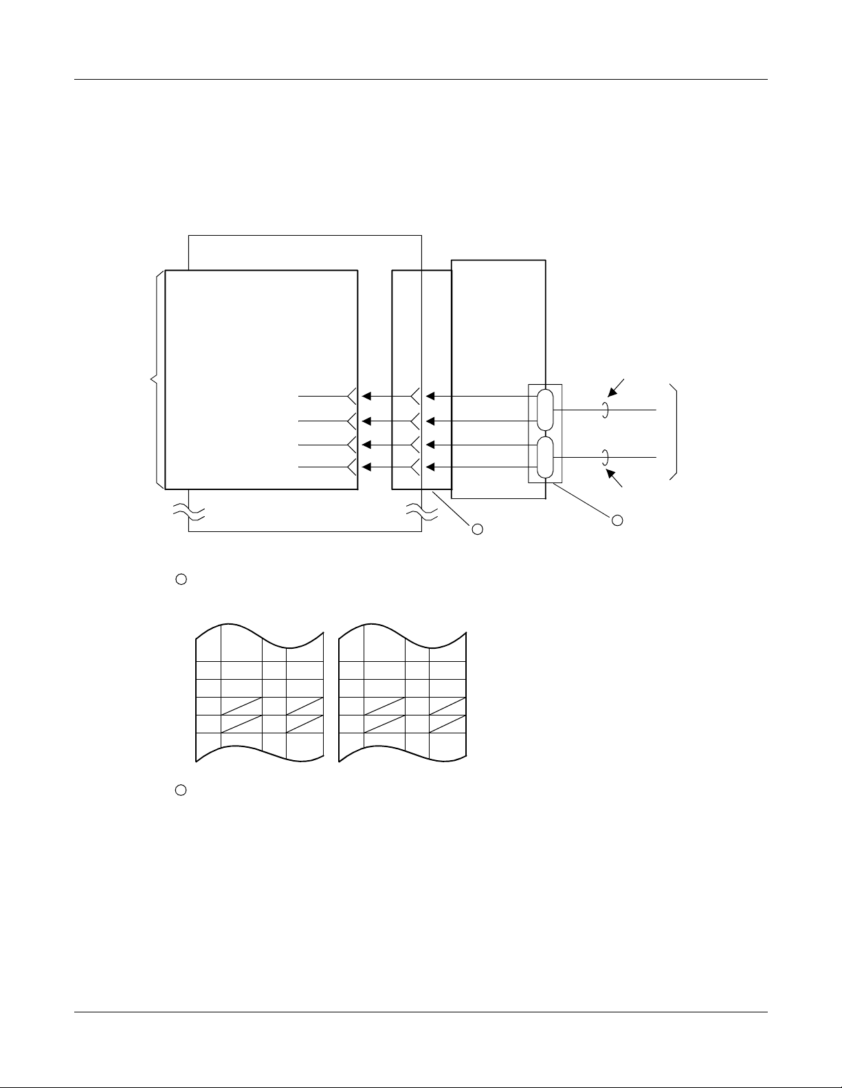
Figure 2-4 shows LTC connector corresponds wi th the AP slots, and DTI pin assignment for ea ch
AP slot.
Figure 2-4 Location of the AP Slots and the LTC Connectors for DTI
L
L
L
L
L
L
L
L
L
L
L
L
T
T
T
T
T
T
T
T
T
T
T
T
0
0
0
0
0
0
0
0
0
0
1
1
0
1
2
3
4
5
6
7
8
9
0
1
/
/
/
/
/
/
/
/
/
/
/
/
A
A
A
A
A
A
A
A
A
A
A
A
P
P
P
P
P
P
P
P
P
P
P
P
0
0
0
0
0
0
0
0
0
0
1
1
0
1
2
3
4
5
6
7
8
9
0
1
01
02
03
04
05
06
07
08
09
10
11
12
13
14
15
16
17
18
19
20
21
22
23
24
25
RA
TA
RA
TA
RA
TA
MJ
LTC0
26
27
28
29
30
31
32
33
34
35
36
37
38
39
40
41
42
43
44
45
46
47
48
49
50
RB
TB
RB
TB
RB
TB
MN
LTC1
RA
01
TA
02
AP00
SLOT
AP01
SLOT
AP02
SLOT
03
04
05
06
07
08
09
10
11
12
13
14
15
16
17
18
19
20
21
22
23
24
25
RA
TA
RA
TA
26
27
28
29
30
31
32
33
34
35
36
37
38
39
40
41
42
43
44
45
46
47
48
49
50
RB
TB
RB
TB
RB
TB
AP03
SLOT
AP04
SLOT
AP05
SLOT
01
02
03
04
05
06
07
08
09
10
11
12
13
14
15
16
17
18
19
20
21
22
23
24
25
RA
TA
RA
TA
RA
TA
LTC2
26
27
28
29
30
31
32
33
34
35
36
37
38
39
40
41
42
43
44
45
46
47
48
49
50
RB
TB
RB
TB
RB
TB
AP06
SLOT
AP07
SLOT
AP08
SLOT
01
02
03
04
05
06
07
08
09
10
11
12
13
14
15
16
17
18
19
20
21
22
23
24
25
RA
TA
RA
TA
RA
TA
LTC3
26
27
28
29
30
31
32
33
34
35
36
37
38
39
40
41
42
43
44
45
46
47
48
49
50
RB
TB
RB
TB
RB
TB
AP09
SLOT
AP10
SLOT
AP11
SLOT
NEAX2000 IVS2 Q-SIG System Manual
ND-70923 (E), Issue 1.0
Page 27
Page 35

CHAPTER 2 INSTALLATION
Installation Procedure
Figure 2-5 shows an example of the cable connection when the 24-DTI/30-DTI card is mounted
in the AP05 slot of PIM0.
Figure 2-5 Example of MDF Cross Connection for DTI
AP05
LTC1 (J)
PIM 0
RA
RB
TA
TB
JP MDF24-DTI/30-DTI
17
42
18
43
LTC1 (P)
LTC1
17
42
18
43
RECEIVE
RA
RB
TA
TB
TRANSFER
TO C SU
17
18
19
20
RA TA42
43
44
45
RB
TB
42
43
44
45
RB TB17
18
19
20
RA
TA
NEAX2000 IVS2 Q-SIG System Manual
Page 28 ND-70923 (E), Issue 1.0
Page 36

CHAPTER 2 INSTALLATION
Installation Procedu re
DTI Cable Connection via CONN Card
When you use an coaxial cabl e, connect the cable to a CSU via the CONN (PZ-M542/M55 7) card
as shown in Figure 2-6.
Figure 2-6 Cable Connection via the CONN Card
BWB
PBX
30-DTI
CONN
LTC0/LTC1/LTC2/LTC3
CONNECTOR
CSU
COAXIAL CABLE
MAX. 6 dB loss at 1024 kHz
NEAX2000 IVS2 Q-SIG System Manual
ND-70923 (E), Issue 1.0
Page 29
Page 37
CHAPTER 2 INSTALLATION
Installation Procedure
Figure 2-7 shows an example of the cable connection when the 24-DTI/30-DTI card is mounted
in the AP05 slot of PIM0.
Figure 2-7 Example of Coaxial Cable Connection
PIM 0
30-DTI
LTC1
JP
CONN
AP05
1 LTC1 CONNECTOR
LTC1 (J)
17
RA TA42
18
19
20
43
44
45
RB
TB
RA
RB
TA
TB
42
43
44
45
17
42
18
43
LTC1 (P)
RB
TB
17
18
19
20
17
42
18
43
RA
TA
RECEIVE
RCV
TO CSU
TRS
SEND
2
1
2 COAXIAL CONNECTOR
NEAX2000 IVS2 Q-SIG System Manual
Page 30 ND-70923 (E), Issue 1.0
Page 38

CHAPTER 3
SYSTEM DATA
PROGRAMMING
This chapter explains the programming procedure to provide Q-SIG
feature on the PBX.
NEAX2000 IVS2 Q-SIG System Manual
ND-70923 (E), Issue 1.0
Page 31
Page 39

CHAPTER 3 SYSTEM DATA PROGRAMMING
How to Read This Chapter
HOW TO READ THIS CHAPTER
In the programming procedure, the meaning of (1), (2) and markings are as follows.
(1) : 1st Data
(2) : 2nd Data
: Initial Data
With the system data clear command (CM00, CM01), the data with this marking is
automatically assigned for each command.
INITIAL
DCH INITIAL
: System Initia lization
After entering the data, system reset is required (Depress SW1 on the MP
card).
: DCH Initialization
A reset of the DCH card is required after data setting.
Set the Make Busy switch to UP and then Down.
Page 32 ND-70923 (E), Issue 1.0
NEAX2000 IVS2 Q-SIG System Manual
Page 40

DTI ASSIGNMENT
CHAPTER 3 SYSTEM DATA PROGRAMMING
DTI Assignment
START
CM05
CM07
CM20
DESCRIPTION DATA
Assign an AP number to the DTI card.
The AP number must match the SENS
switch setting on the DTI card.
INITIAL
Assign a Q-SIG trunk number to each
channel number on the DTI card.
INITIAL
The system allocates time slots to
consecutive channels from lowest to
highest channel number assigned. To
minimize the number of time slots
allocated, assign trunk numbers to the
consecutive channels on each card.
Never skip channels in CM07.
Assign the access code for Q-SIG to LCR
Group 0-3.
•
Y=0
(1)
04-15, 20-31: AP No.
(2)
09: DTI card
•
YY=01
(1)
XX ZZ
XX: 04-15, 20-31: AP No. assigned by
CM05 Y=0
ZZ: 01-15, 17-31: Channel No. of DTI
D000-D255: Trunk No.
(2)
Trunk No. already assigned by CM10
cannot be used.
•
Y=0-3 Numbering Plan Group 0-3
(1)
X-XXXX: Access code
(2)
A126-A129: LCR Group 0-3
NOTE 1
A
NEAX2000 IVS2 Q-SIG System Manual
ND-70923 (E), Issue 1.0
Page 33
Page 41

CHAPTER 3 SYSTEM DATA PROGRAMMING
DTI Assignment
A
CM30
DESCRIPTION DATA
Assign a trunk route to ea ch Q-SIG trunk
used for voice channel (B Channel), and
also to signaling channel (D Channel).
NOTE 1: DTI route must be separated
from analog trunk routes.
NOTE 2: The trunk routes for D Channel
must be different from the trunk
routes for B Channel.
Assign the trunk route data to each Q-SIG
incoming trunk used for voice channel
only.
YY=00
•
000-255: Trunk No. assigned by CM07
(1)
YY=01
00-63: Trunk Route No.
(2)
YY=02 Day Mode
•
YY=03 Night Mode
•
YY=40 Mode A
•
YY=41 Mode B
•
000-255: Trunk No. assigne d by CM07
(1)
YY=01
04: Direct-In Termination
(2)
21: Dial-in Termination
YY=07
Assign CIC (Circuit Identification Code)
number to each Q-SIG trunk used for
voice channel only.
NOTE: CIC number must not be as-
signed to the trunk number of D
Channel: TS 16 (30DTI).
•
000-255: Trunk No. assigned by CM07
(1)
YY=01
000-029: CIC No.
(2)
EXAMPLE OF 30DTI
B Channel trunk No.: D100-D114, D116-
D130
D Channel trunk No.: D115
(1) 100-114, 116-130
(2) 000-014, 015-029
EXAMPLE OF 24DTI
B Channel trunk No.:D100-D122
D Channel trunk No.:D123
(1) 100-122
B
(2) 123
Page 34 ND-70923 (E), Issue 1.0
NEAX2000 IVS2 Q-SIG System Manual
Page 42

CHAPTER 3 SYSTEM DATA PROGRAMMING
DTI Assignment
B
CM35
DESCRIPTION DATA
Assign the trunk route data to the DTI
route number assigned by CM30 Y=00.
NOTE: CM35 YY=00, 04, 05, 09, 15 and
19 should be assigned to only
the B Channel trunk routes.
For D Channel trunk route, no
data setting is required.
•
YY=00 Kind of Trunk Route
(1)
00-63: B Channel Trunk Route No.
(2)
04: Tie Line trunk
YY=04
•
Answer Signal from distant office
00-63: B Channel Trunk Route No.
(1)
2: Answer signal arrives
(2)
•
YY=05
Release Signal from distant office
(1)
00-63: B Channel Trunk Route No.
(2)
1 : Release signal arrives
•
YY=09 Incoming Connection Signaling
(1)
00-63: B Channel Trunk Route No.
(2)
08: ISDN/Q-SIG
YY=15 Kind of Call Termination
•
Indicator Key/Lamp on ATT
00-63: B Channel Trunk Route No.
(1)
00-07: C.O. Incoming 0-7
(2)
YY=19 DTI PAD
[For Australia]
PAD DATA OF DTI [dB]
CONNECTION
PATTERNS
Station-DTI 0/0
Tone-DTI 0/0
COT/DID/LDT-
DTI
ODT-DTI 0/0
DTI-DTI 0/0
T/R : Transmitter PAD/Receiver PAD
+: Gain
– : Loss
DATA
=4
(T/R)
DAT A
=5
(T/R)
DATA
=6
(T/R)
DATA
=7
(T/R)
0/0
•
YY=19
(1)
00-63: B Channel Trunk Route No.
(2)
0-3: Programmable PAD
(See CM42)
4-7 : Fixed PAD
C
NEAX2000 IVS2 Q-SIG System Manual
ND-70923 (E), Issue 1.0
Page 35
Page 43

CHAPTER 3 SYSTEM DATA PROGRAMMING
DTI Assignment
C
CM35
DESCRIPTION DATA
YY=19 DTI PAD
[For North America/Other Countries]
PAD DATA OF DTI [dB]
CONNECTION
PATTERNS
Station-DTI –3/–8 –3/–3 –3/–3 –3/–8
Tone-DTI 0/0 0/0 0/0 0/0
COT/DID/LDT/ODT
(2W E&M)-DTI
ODT (4W E&M)-DTI +3/–3 0/0 0/0 +3/–3
DTI-DTI 0/–6 0/0 0/–6 0/0
T/R : Transmit PAD/Receive PAD
+: Gain
– : Loss
Assign Q-SIG to the B Channel trunk
routes and the D Channel trunk route.
DAT
A=4
(T/R)
DAT
A=5
(T/R)
0/0 0/0 0/0 0/0
DAT
A=6
(T/R)
DAT
A=7
(T/R)
YY=90
•
Assignment of DTI route for Q-SIG
00-63: B Channel /D Channel Trunk
(1)
Route No.
5: Q-SIG (ETS300 172)
(2)
END
Assign the LAPD mode of the D Channel
trunk route.
This data setting must not be identical
with the opposite PBX.
If the opposite PBX is defined as a
“Network Mode”, set this data to 1 (User
Mode).
DCH INITIAL
•
YYY=113
(1)
00-63: D Channel Trunk Route No.
(2)
0 : Network Mode
1 : User Mode
Page 36 ND-70923 (E), Issue 1.0
NEAX2000 IVS2 Q-SIG System Manual
Page 44
DCH ASSIGNMENT
CHAPTER 3 SYSTEM DATA PROGRAMMING
DCH Assignment
START
CM05
CM06
CM35
CMA9
END
DESCRIPTION DATA
Assign an AP number to the DCH card.
The AP number must match the SENS
switch setting on the DCH card.
INITIAL
Assign the DCH number to the AP
number of DCH assigned by CM05.
INITIAL
Assign the DCH number to the Q-SIG
trunk route assigned by CM30 YY=00.
NOTE: This data should be assigned to
only the B Channel trunk routes.
Assign the trunk number assigned by
CM07 YY=01 to each DCH number for
providing D Channel path between DTI
and DCH.
•
Y=0
(1)
04-15, 20-31: AP No.
(2)
32: DCH card for Q-SIG
•
YY=08
(1)
0-7: DCH No.
(2)
04-15, 20-31: AP No. assigned by
CM05 Y=0
•
YY=93 Assignment of DCH
(1)
00-63: B Channel Trunk Route No.
(2)
00-07: DCH No. assigned by CM06
•
YY=00
(1)
0-7: DCH No. assigned by CM06
(2)
000-255: Trunk No. assigned by CM07
YY=01
NEAX2000 IVS2 Q-SIG System Manual
ND-70923 (E), Issue 1.0
Page 37
Page 45

CHAPTER 3 SYSTEM DATA PROGRAMMING
Tandem Connection As signment
TANDEM CONNECTION ASSIGNMENT
To provide Tandem Connection (Tie Line to Q-SIG, Q-SIG to Tie Line), do the following
programming.
START
CM08
CM36
CM41
DESCRIPTION DATA
Specify whether the busy tone is sent to a
calling party of Q-SIG when a called party
is busy in the tandem connection (Q-SIG
to COT).
Specify the combination of trunk routes
allowing the tandem connection.
Specify the timing start when making a QSIG call from a station (PB/DP telephon e,
term
D
) or Attendant Console for the
tandem connection.
NOTE 1: By using this command, a
Q-SIG call is available even if
“#” is not dialed.
(1)
407
(2)
0 : Available (BT)
1 : Not available (RBT)
(1)
XX YY
XX : 00-63 (Incoming Trunk Route)
YY : 00-63 (Outgoing Trunk Route)
(2)
0 : Allow
1 : Restricted
•
Y=0
(1)
57
(2)
03-14: 3-14 sec. (1 sec. increments)
If no data i s s et, the timing start is not
effective.
NOTE 2: This command is effective for
dialing a called number. When
dialing a called party
subaddress, this command is
not effective.
END
Page 38 ND-70923 (E), Issue 1.0
NEAX2000 IVS2 Q-SIG System Manual
Page 46

CHAPTER 3 SYSTEM DATA PROGRAMMING
Connected D estination Indication Assignment
CONNECTED DESTINATION INDICATION ASSIGNMENT
To send own office number with the answering station (single line telephone, D
the calling party, do the following programming.
START
CMA9
END
Assign the own office number sent with
the answering station number, if required.
DESCRIPTION DATA
•
YY=01
(1)
0-7: DCH No.
(2)
DCH INITIAL
0-999: Own Office No.
term
) number to
NEAX2000 IVS2 Q-SIG System Manual
ND-70923 (E), Issue 1.0
Page 39
Page 47

CHAPTER 4
CIRCUIT CARD
INFORMATION
This chapter explains the mounting location, the meaning of lamp
indications, and the method of switch settings of each circuit card for
the Q-SIG.
NEAX2000 IVS2 Q-SIG System Manual
ND-70923 (E), Issue 1.0
Page 41
Page 48

CHAPTER 4 CIRCUIT CARD INFORMATION
How to Read This Chapter
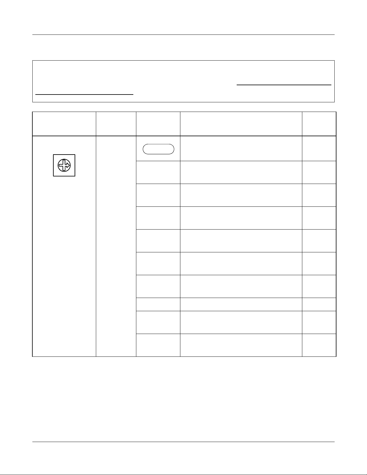
HOW TO READ THIS CHAPTER
This chapter explains each circuit card used in this system about the following items.
Explanations are given in alphabetical order of the circuit card names within each circuit card
category (Control, Application Processor, and Line/Trunk).
(1) Locations of Lamps, Switches, and Connectors
The locations of lamps, switches, and connectors of each circuit card are shown by a face
layout.
(2) Lamp Indications
The name, color, and functions of each indicator lamp equipped on each circui t card are
described in a table.
(3) Switch Settings
The name, settings, and fun cti on s of ea ch switch equipped on each circuit card are
described in a table.
Each switch setting table has a “CHECK” column. Make necessary entries in the CHECK column
during and/or after the system installation and maintenance, and use each table as a reference
for subsequent system maintenance and operations.
Page 42 ND-70923 (E), Issue 1.0
NEAX2000 IVS2 Q-SIG System Manual
Page 49

CHAPTER 4 CIRCUIT CARD INFORMATION
Mounting Location of Circuit Card
MOUNTING LOCATION OF CIRCUIT CARD
This section explains the conditions for mounting circuit cards for the Q-SIG.
Figure 4-1 shows circuit card mounting slots allocated in the PIM.
Figure 4-1 Mounting Location of Circuit Card
LT09/AP09
LT08/AP08
VM
LT00/AP00
LT01/AP01
LT02/AP02
LT03/AP03
LT04/AP04
LT05/AP05
LT06/AP06
LT07/AP07
LT10/AP10
LT11/AP11/FP11
MP12/FP12
PFT
PIM
0~7
AC/DC
PWR
DC/DC
PWR
LTC0
LTC1
BWB
FRONT
LTC3
*1
*3
*2
LTC2
*1: PN-CP14 (MP) card on the MP12 s l ot on PIM0.
*2: The following application processor card mounted on the AP00-AP11 slots on PIM0-7.
PN-24DTA-C (DTI)
PN-30DTC-A (DTI)
PN-SC01 (DCH)
*3: PZ-M542/PZ-M557 (CONN) card on the LTC0-LTC3 connectors on the PIM which
accommodates 24DTI/30DTI card.
NEAX2000 IVS2 Q-SIG System Manual
ND-70923 (E), Issue 1.0
Page 43
Page 50
CHAPTER 4 CIRCUIT CARD INFORMATION
List of Required Circuit Card
LIST OF REQUIRED CIRCUIT CARD
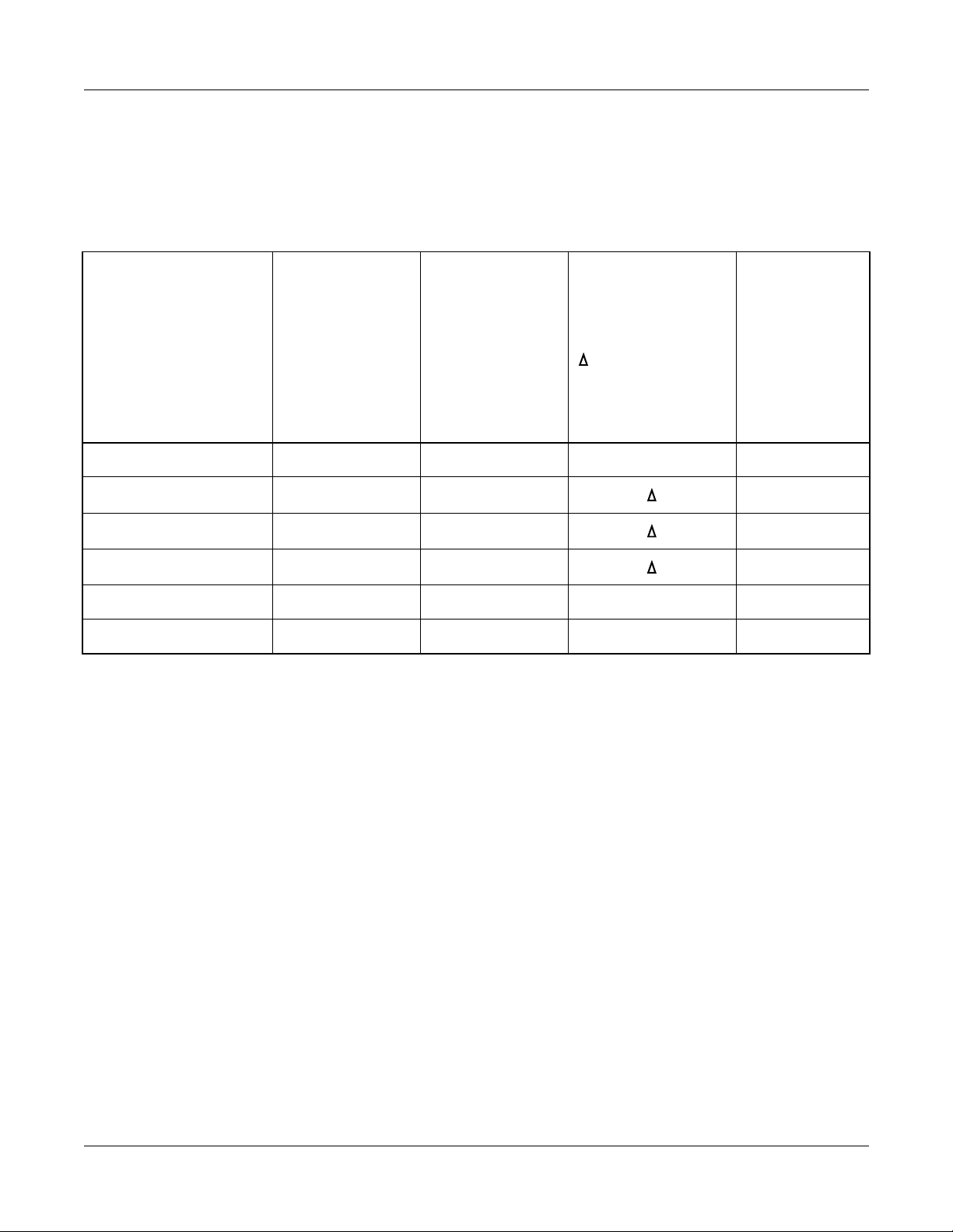
Table 4-1 shows the required circuit cards to be explained in this section.
Table 4-1 List of Required Circuit Card
EXTRACTION/
INSERTION WITH
NAME
(FUNCTIONAL
NAME)
LAMP
X:PROVIDED
–: NOT
PROVIDED
SWITCH
X:PROVIDED
–: NOT
PROVIDED
PN-CP14 (MP) X X – Page 45
PN-30DTC-A (DTI) X X Page 50
POWER ON
X:ALLOWED
:ALLOWED
AFTER MB*
–: NOT
ALLOWED
REFERENCE
PAGE
PN-24DTA-C (DTI) X X Page 56
PN-SC01 (DCH) X X Page 62
PZ-M542 (CONN) – X X Page 65
PZ-M557 (CONN) – X X Page 67
*MB = Make Busy
Page 44 ND-70923 (E), Issue 1.0
NEAX2000 IVS2 Q-SIG System Manual
Page 51

PN-CP14 (MP)
Locations of Lamps, Switches, and Connectors
CHAPTER 4 CIRCUIT CARD INFORMATION
List of Required Circuit Card
SW4
CONN
VR
JP1
JP0
CONN: To CONNR connector on PZ-M537 (EXPMEM)
SW3
RUN
SW1
SW2
JACK
CLK
DK
RS1
RS0
Lamp Indicat i ons
LAMP
COLOR FUNCTION
NAME
RUN Green Flashes at 120 IPM while this card is operating normally.
CLK Green Remains lit while receiving clock signals to the PLO.
NEAX2000 IVS2 Q-SIG System Manual
ND-70923 (E), Issue 1.0
Page 45
Page 52
CHAPTER 4 CIRCUIT CARD INFORMATION
List of Required Circuit Card
Switch Settings
Caution
When the operating pow e r is bei ng su pp l ie d to this circu it card , do not plug/unplug this circuit
card into/from its mounting slot.
SWITCH NAME
SW3 (Rotary SW)
0
NO T E 1
SWITCH
NUMBER
0-F
SETTING
POSITION
0
2
3
5
NO T E 2
6
NO T E 2
7
NO T E 2
8
NO T E 2
FUNCTION CHECK
On Line
(Call processing is in progress)
Off Line (Call processing is stopped)
• I/O port: As per CM40 YY=08
Off Line (Call processing is stopped)
• I/O port: 9600 bps (Fixed)
Off Line (Call processing is stopped)
• I/O port: 9600 bps
Off Line (Call processing is stopped)
• I/O port: 19200 bps
Off Line (Call processing is stopped)
• I/O port: 38400 bps
Off Line (Call processing is stopped)
• I/O port: 57600 bps
B For clearing the office da ta
For setting the resident system
C
1, 4, 9
program
Not used
A, D-F
(Continued)
NOTE 1: Set the groove on the switch to the desired position.
NOTE 2: Only when executing “MP Pr ogr a m Do w nl oad” in MATWorX, set the SW3 to 5-8.
Page 46 ND-70923 (E), Issue 1.0
NEAX2000 IVS2 Q-SIG System Manual
Page 53

CHAPTER 4 CIRCUIT CARD INFORMATION
List of Required Circuit Card
SWITCH NAME
SWITCH
NUMBER
SETTING
POSITION
FUNCTION CHECK
SW1 (Push SW) For initializing CPU
SW2
(Piano Key SW)
OFF
4
3
2
1
ON
1
2, 3
ON A-law (Australia)
OFF µ-law (North America)
Selection of PLO0 input
(Phase Locked Oscillator)
• For clock receiver office:
SW2-2 SW2-3 FUNCTION
OFF OFF 1.5 MHz clock
[For PN-24DTA-C/PN-24PRTA]
ON OFF 1 92 kHz clock
[For PN-BRTA]
OFF ON 2 MHz clock
[For PN-30DTC-A/PN-2BRTC]
ON ON Not used
• For clock source office:
SW2-2 SW2-3
OFF OFF
When using RS1 port for built-in
ON
4
MODEM
OFF When using RS1 port for RS-232C
(Continued)
NEAX2000 IVS2 Q-SIG System Manual
ND-70923 (E), Issue 1.0
Page 47
Page 54

CHAPTER 4 CIRCUIT CARD INFORMATION
List of Required Circuit Card
SWITCH NAME
SW4 (Dip SW)
ON
123
4
SWITCH
NUMBER
1 Not used
2 Not used
SETTING
POSITION
OFF
OFF
Selection of PLO1 input
(Phase Locked Oscillator)
• For clock receiver office:
SW4-3 SW4-4 FUNCTION
OFF OFF 1.5 MHz clock
3, 4
ON OFF 192 kHz clock
OFF ON 2 MHz clock
ON ON Not used
FUNCTION CHECK
[For PN-24DTA-C/PN-24PRTA]
[For PN-BRTA]
[For PN-30DTC-A/PN-2BRTC]
• For clock source office:
SW4-3 SW4-4
OFF OFF
VR (Rotary SW) Variable Resister for External Hold
20
Tone Source
(0 - 20 Kohms : Clockwise)
0
DK (Connector)
02
01
02 Ground detec tion
01 Ground sending
(Continued)
Page 48 ND-70923 (E), Issue 1.0
NEAX2000 IVS2 Q-SIG System Manual
Page 55

CHAPTER 4 CIRCUIT CARD INFORMATION
List of Required Circuit Card
SWITCH NAME
JP0 (Jumper pin)
SWITCH
NUMBER
SETTING
POSITION
FUNCTION CHECK
Not used
UP
(Memory backup OFF)
Front
DOWN
For normal oper ation
(Memory backup ON)
JP1 (Jumper pin)
For using internal tone source
Front
UP
DOWN For using external tone source
The figure in the SWITCH NAME column and the position in in the SETTING POSITION
column indicate the standard setting of the switch. When the switch is not set as shown by the
figure and , the setting of the switch varies with the system concerned.
NEAX2000 IVS2 Q-SIG System Manual
ND-70923 (E), Issue 1.0
Page 49
Page 56

CHAPTER 4 CIRCUIT CARD INFORMATION
List of Required Circuit Card
PN-30DTC-A (DTI)
Locations of Lamps, Switches and Connectors
JPS
SENS
RUN
MB
SW
PCM
FRM
MFRM
RMT
MRMT
AIS
BL
JPR
JP
Page 50 ND-70923 (E), Issue 1.0
NEAX2000 IVS2 Q-SIG System Manual
Page 57

Lamp Indicat i ons
CHAPTER 4 CIRCUIT CARD INFORMATION
List of Required Circuit Card
LAMP
NAME
RUN Green Flashes at 120 IPM when this card is normally operating.
PCM Red Remains lit when detecting PCM signal loss.
FRM Red Remains lit when detecting Frame Alignment signal loss.
MFRM Red Remains lit when detect ing Multi -Frame Alig nment signal loss on
RMT Red Remains lit when receiving the alarm from a distant office
MRMT Red Remains lit when receiving the alarm from a distant office
AIS Red Remains lit when indicating that the pattern of consecutive “1” is
COLOR FUNCTION
time Slot 16.
because Frame Alignment signal loss has been detected at the
distant office.
because Multi-Frame Alignme nt signal loss has been detected
at the distant off ic e.
being received. The distant office transmits this signal for a loopback test distant.
BL Red B Channel status
ON : More than10 channels are busy
OFF : All channels are idle
Flash (60 IPM) : Only one channel is busy
Flash (120 IPM) : 2 to 10 channels are busy
NEAX2000 IVS2 Q-SIG System Manual
ND-70923 (E), Issue 1.0
Page 51
Page 58

CHAPTER 4 CIRCUIT CARD INFORMATION
List of Required Circuit Card
Switch Settings
SWITCH
NAME
SENS
(Rotary SW)
F
4
NO T E 1
MB (Toggle SW)
ON
NO T E 2
SWITCH
NUMBER
SETTING
POSITION
FUNCTION CHECK
4-F Set the switch to match the AP Number (04-31) to
be set by CM05.
AP No.
SW-8: ON
SW-8: OFF
SW No.
04 05 06 07 08 09 10 11 12 13 14 15
20 21 22 23 24 25 26 27 28 29 30 31
456789ABCDEF
0-3 Not used
UP For make-busy
DOWN
For normal operation
(Continued)
Page 52 ND-70923 (E), Issue 1.0
NEAX2000 IVS2 Q-SIG System Manual
Page 59

CHAPTER 4 CIRCUIT CARD INFORMATION
List of Required Circuit Card
SWITCH
NAME
SW
(Piano Key SW)
OFF
8
7
6
5
4
3
2
1
ON
SWITCH
NUMBER
1
NO T E 3
NO T E 4
2
NO T E 3
NO T E 4
3
4
SETTING
FUNCTION CHECK
POSITION
ON
OFF
ON
OFF
ON Remote loop-back
OFF
ON Local loop-back (AIS send)
OFF
Source clock signal from network is
sent to the PLO 0 input on MP card.
Source clock signal from network is
not sent to the PLO 0 input on MP
card
Source clock signal from network is
sent to the PLO 1 input on MP card.
Source clock signal from network is
not sent to the PLO 1 input on MP
card.
For normal operation
For normal operation
ON
Transmission line cable:
Coaxial cable (75 ohms)
5
Transmission line cable:
OFF
6
OFF
Twisted-pair cable (120 ohms)
Always set to OFF
7
OFF
ON AP No. 04-15
8
OFF AP No. 20-31
(Continued)
NEAX2000 IVS2 Q-SIG System Manual
ND-70923 (E), Issue 1.0
Page 53
Page 60

CHAPTER 4 CIRCUIT CARD INFORMATION
List of Required Circuit Card
SWITCH
NAME
JPS
(Jumper pin)
JPR
(Jumper pin)
JP
(Jumper pin)
SWITCH
NUMBER
SETTING
POSITION
UP
DOWN
UP
DOWN
RIGHT
LEFT
FUNCTION CHECK
Balanced tran smission
(For twisted-pair cable)
TA is grounded on the tra nsm issi on
line (For coaxial cable)
Balanced tran smission
(For twisted-pair cable)
RA is grounded on the trans mission
line (For coaxial cable)
Line impedance: 75 ohms
(For coaxial cable)
Line impedance: 120 ohms
(For twisted-pair cable)
(Continued)
The figure in the SWITCH NAME column and the position in in the SETTING POSITION
column indicate the standard setting of the switch. When the switch is not set as shown by the
figure and , the setting of the switch varies with the system concerned.
NOTE 1: Set the groove on the switch to the desired position.
NOTE 2: When the power is on, flip the MB switch to ON (UP position) before plugging/
unplugging the circu it car d.
Page 54 ND-70923 (E), Issue 1.0
NEAX2000 IVS2 Q-SIG System Manual
Page 61

NOTE 3: Set the SW-1 and SW-2 as follows:
DTI0 DTI1 DTI2 DTI3
CHAPTER 4 CIRCUIT CARD INFORMATION
List of Required Circuit Card
CONDITIONS
SW-1SW-2SW-1SW-2SW-1SW-2SW-1SW
REMARKS
-2
When one DTI is
ON OFF – – – – – –
provided.
When more than
one DTI is
ON OFF OFF ON OFF OFF OFF OFF
provided.
NOTE 4: When the PBX is a clock source office, set the SW-1 and SW-2 on all the DTI cards
mounted in PIM0 to “OFF”.
MP card will receive the
clock signal from DTI0
at its PLO0 input.
MP card will receive the
clock signal from DTI0
at its PLO0 input, under
normal conditions.
Should a clock failure
occur with DTI0, MP
card will automatically
switch to the PLO1 input
which gets from DTI1.
NOTE 5: Mount the DTI card which receives a source clock signal into PIM0.
NEAX2000 IVS2 Q-SIG System Manual
ND-70923 (E), Issue 1.0
Page 55
Page 62

CHAPTER 4 CIRCUIT CARD INFORMATION
List of Required Circuit Card
PN-24DTA-C (DTI)
Locations of Lamps, Switches, and Connectors
MAS
SENSE
RUN
MB
SW1
SW0
JPR0
JRR1
JPS
AISS
CRC
PCM
FRM
RMT
AIS
BL
Page 56 ND-70923 (E), Issue 1.0
NEAX2000 IVS2 Q-SIG System Manual
Page 63

Lamp Indicat i ons
CHAPTER 4 CIRCUIT CARD INFORMATION
List of Required Circuit Card
LAMP
NAME
RUN Green Flashes at 120 IPM while this card is operating normall y.
CRC Red Remains lit when detecting Cyclic Redundancy Checking (CRC)
PCM Red Remains lit when detecting PCM signal loss.
FRM Red Remains lit when detecting Frame Alignment signal loss.
RMT Red Remains lit when receiving Frame Alignment signal loss alarm
AIS Red Remains lit when a pattern of consecutive “1” is received. The
BL Red B Channel status
COLOR FUNCTION
errors.
from a distant office.
distant office transmits this signal for a loop-back test.
ON : More than 10 channels are busy
OFF : All channels are idle
Flash (60 IPM) : Only one channel is busy
Flash (120 IPM) : 2 through 10 channels are busy
NEAX2000 IVS2 Q-SIG System Manual
ND-70923 (E), Issue 1.0
Page 57
Page 64

CHAPTER 4 CIRCUIT CARD INFORMATION
List of Required Circuit Card
Switch Settings
SWITCH NAME
SENSE
(Rotary SW)
F
4
NO T E 1
MB (Toggle SW)
ON
NO T E 2
SWITCH
NUMBER
SETTING
POSITION
FUNCTION CHECK
0-3 Not used
4-F Set the switch to match the AP Number (04-31) to
be set by CM05.
AP No.
SW1-4: ON
SW1-4: OFF
SW No.
04 05 06 07 08 09 10 11 12 13 14 15
20 21 22 23 24 25 26 27 28 29 30 31
456789ABCDEF
UP For ma ke-busy
DOWN
For normal operation
(Continued)
Page 58 ND-70923 (E), Issue 1.0
NEAX2000 IVS2 Q-SIG System Manual
Page 65

CHAPTER 4 CIRCUIT CARD INFORMATION
List of Required Circuit Card
SWITCH NAME
SW0
(Piano K ey SW)
OFF
8
7
6
5
4
3
2
1
ON
SWITCH
NUMBER
1
NOTE 3
NOTE 4
2
NOTE 3
NOTE 4
3
4
SETTING
POSITION
ON
OFF
ON
OFF
ON
OFF
ON
OFF
FUNCTION CHECK
Source clock signal from network is
sent to the PLO 0 input on MP card.
Source clock signal from network is
not sent to the PLO 0 input on MP
card.
Source clock signal from network is
sent to the PLO 1 input on MP card.
Source clock signal from network is
not sent to the PLO 1 input on MP
card.
Remote loop-back
For normal operation
Local loop-back (AIS send)
For normal operation
ON
5
OFF
ON
Set equalize r accordin g to the cab l e
length between the PBX and the
MDF.
SW0-5 SW0-6 SW0-7
6
OFF
ON ON
ON
7
OFF
8 Not used
OFF
CABLE LENGTH
ONON ON
0-40m (0-131.2 ft.)
OFF
40-80m (131.2-262.5 ft.)
80-120m (262.5-394 ft.)
ONON OFF
120-160m (394-525 ft.)
OFFON OFF
160-200m (525-656 ft.)
ONOFF ON
Signal is not sent
OFFOFF OFF
(Continued)
NEAX2000 IVS2 Q-SIG System Manual
ND-70923 (E), Issue 1.0
Page 59
Page 66

CHAPTER 4 CIRCUIT CARD INFORMATION
List of Required Circuit Card
SWITCH NAME
SW1
(Piano K ey SW)
OFF
4
3
2
1
ON
NO T E 4
JPR0 (Jumper pin)
JPR1 (Jumper pin)
SWITCH
NUMBER
1 Not used
2 Not used
3 Not used
SETTING
POSITION
OFF
OFF
OFF
ON AP No. 04-15
4
OFF AP No. 20-31
UP
DOWN
Right
FUNCTION CHECK
Neutral grounding on the receiving
line is provided.
Neutral grounding on the receiving
line is not provided.
Line impedance: 100 ohms
Left Line impe dance: 110 ohms
JPS (Jumper pin)
Neutral grounding on the transmit-
UP
ting line is provided.
Neutral grounding on the transmit-
MAS (Jumper pin)
DOWN
UP Clock Source
DOWN
ting line is not provided.
Clock Receiver
AISS (Jumper pin) AIS signal is sent ou t when make-
UP
DOWN
busy or power on.
AIS signal is not sent out when
make-busy or powe r on.
(Continued)
The figure in the SWITCH NAME colu mn and the position in in the SETTING POSITIONcolumn indicate the standard setting of the switch. When the switch is not set as shown by the
figure and , the setting of the switch varies with the system concerned.
Page 60 ND-70923 (E), Issue 1.0
NEAX2000 IVS2 Q-SIG System Manual
Page 67

CHAPTER 4 CIRCUIT CARD INFORMATION
List of Required Circuit Card
NOTE 1: Set the groove on the switch to the desired position.
NOTE 2: When the power is on, flip the MB switch to ON (UP position) before plugging/
unplugging the circui t card.
NOTE 3: Set SW0-1 and SW0-2 as follows:
DTI0 DTI1 DTI2 DTI3 DTI4
CONDITIONS
SW
0-1SW0-2SW0-1SW0-2SW0-1SW0-2SW0-1SW0-2SW0-1SW0-2
REMARKS
When one DTI is
provided.
When more than
one DTI is provided.
ONOFF––––––––
ON OFF OFF ON OFF OFF OFF OFF OFF OFF
MP card will receive the
clock signal from DTI0 at its
PLO0 input.
MP card will receive the
clock signal from DTI0 at its
PLO0 input, under normal
conditions.
Should a clock failure occur
with DTI0, MP card will automatically switch to the PLO1
input which gets clock from
DTI1.
NOTE 4: When the PBX is a clock source office, set the SW0-1 and SW0-2 on all the DTI cards
mounted in PIM0 to “OFF”.
NOTE 5: Mount the DTI card which receives a source clock signal into PIM0.
NEAX2000 IVS2 Q-SIG System Manual
ND-70923 (E), Issue 1.0
Page 61
Page 68

CHAPTER 4 CIRCUIT CARD INFORMATION
List of Required Circuit Card
PN-SC01 (DCH)
Locations of Lamps, Switches and Connectors
SW1
SENS
RUN
MB
SW0
LC
LPB
Lamp Indicat i ons
LAMP
COLOR FUNCTION
NAME
RUN Green Flashes at 120 IPM while this card is operating normally.
LC Green Remain s lit when com municat ions ar e norma lly o ngoing w ith th e
D Channel data links connected.
LPB Green Not used
Page 62 ND-70923 (E), Issue 1.0
NEAX2000 IVS2 Q-SIG System Manual
Page 69

Switch Settings
CHAPTER 4 CIRCUIT CARD INFORMATION
List of Required Circuit Card
SWITCH
NAME
SENS
(Rotary SW)
F
4
NO T E 1
MB (Toggle SW)
ON
NO T E 2
SW0
(Piano Key SW)
SWITCH
NUMBER
SETTING
POSITION
FUNCTION CHECK
4-F Set the switch to match the AP Number (04-31) to
be set by CM05.
AP No.
SW0-4: ON
SW0-4: OFF
SW No.
04 05 06 07 08 09 10 11 12 13 14 15
20 21 22 23 24 25 26 27 28 29 30 31
456789ABCDEF
0-3 Not used
UP For make-busy
DOWN
1 Always set to OFF
OFF
For normal operation
OFF
2 Always set to OFF
4
3
2
1
ON
3 Always set to OFF
OFF
OFF
ON AP No. 04-15
4
OFF AP No. 20-31
(Continued)
NEAX2000 IVS2 Q-SIG System Manual
ND-70923 (E), Issue 1.0
Page 63
Page 70

CHAPTER 4 CIRCUIT CARD INFORMATION
List of Required Circuit Card
SWITCH
NAME
SW1 (Dip SW)
ON
1234567
SWITCH
NUMBER
8
SETTING
FUNCTION CHECK
POSITION
1 Always set to OFF
2 Always set to OFF
3 Always set to OFF
4 Always set to OFF
5 Always set to OFF
6 Always set to OFF
7 Always set to OFF
OFF
OFF
OFF
OFF
OFF
OFF
OFF
8 Always set to OFF
OFF
The figure in the SWITCH NAME column and the position in in the SETTING POSITION
column indicate the standard setting of the switch. When the switch is not set as shown by the
figure and , the setting of the switch varies with the system concerned.
NOTE 1: Set the groove on the switch to the desired position.
NOTE 2: When the power is on, flip the MB switch to ON (UP position) before plugging/
unplugging the circu it car d.
Page 64 ND-70923 (E), Issue 1.0
NEAX2000 IVS2 Q-SIG System Manual
Page 71

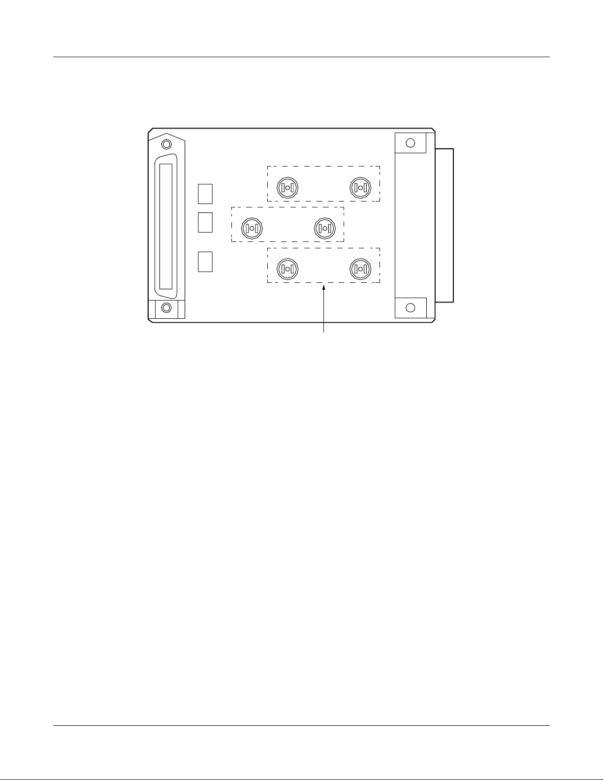
PZ-M542 (CONN)
Locations of Lamps, Switches and Connectors
CHAPTER 4 CIRCUIT CARD INFORMATION
List of Required Circuit Card
TO CHAMP
CONNECTOR (MDF)
Lamp Indicat i ons
This card has no lamps.
TRS21
JP2
LTC
JP1
JP0
FOR
No.1
CIRCUIT
RCV01
TRS11
COAXIAL CONNECTOR
RCV21
TRS01
FOR
No.2
CIRCUIT
RCV11
FOR
No.0
CIRCUIT
LT
TO LTC CONNECTOR
ON BWB IN PIM
NEAX2000 IVS2 Q-SIG System Manual
ND-70923 (E), Issue 1.0
Page 65
Page 72

CHAPTER 4 CIRCUIT CARD INFORMATION
List of Required Circuit Card
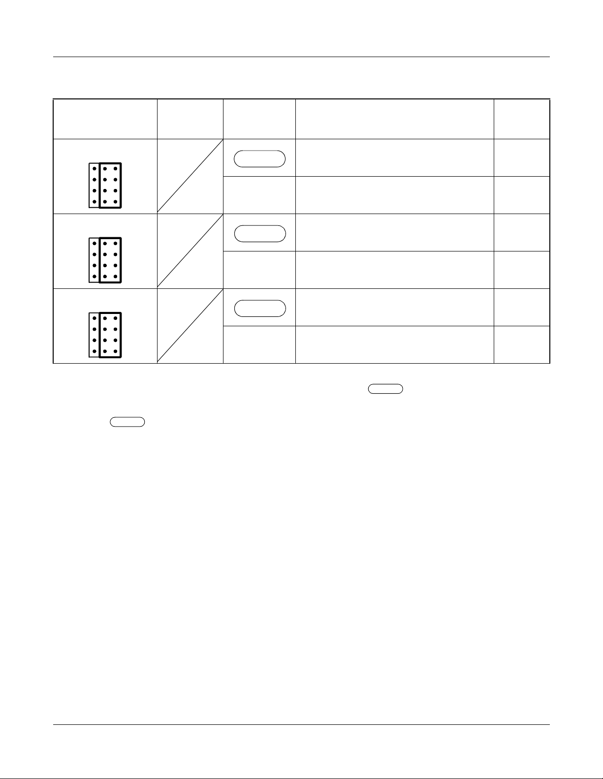
Switch Settings
SWITCH NAME
SWITCH
NUMBER
SETTING
POSITION
FUNCTION CHECK
JP0 For coaxial connectors
RIGHT
(No.0 circuit)
For champ connector
LEFT
(LT connector) (No.0 circuit)
JP1 For coaxial connectors
RIGHT
LEFT
(No.1 circuit)
For champ connector
(LT connector) (No.1 circuit)
JP2 For coaxial connectors
RIGHT
(No.2 circuit)
For champ connector
LEFT
(LT connector) (No.2 circuit)
The figure in the SWITCH NAME column an d the position in in the SETTING POSITION
column indicate the standard setting of the switch. When the switch is not set as shown by the
figure and , the setting of the switch varies with the system concerned.
Page 66 ND-70923 (E), Issue 1.0
NEAX2000 IVS2 Q-SIG System Manual
Page 73
PZ-M557 (CONN)
Locations of Lamps, Switches and Connectors
CHAPTER 4 CIRCUIT CARD INFORMATION
List of Required Circuit Card
TO CHAMP
CONNECTOR (MDF)
Lamp Indicat i ons
This card has no lamps.
FOR
No.2
JP2
LTC
JP1
JP0
CIRCUIT
TRS10
FOR
No.0
CIRCUIT
TRS20
RCV10
RCV00
COAXIAL CONNECTOR
RCV20
FOR
No.1
CIRCUIT
TRS00
LT
TO LTC CONNECTOR
ON BWB IN PIM
NEAX2000 IVS2 Q-SIG System Manual
ND-70923 (E), Issue 1.0
Page 67
Page 74
CHAPTER 4 CIRCUIT CARD INFORMATION
List of Required Circuit Card
Switch Settings
SWITCH NAME
SWITCH
NUMBER
SETTING
POSITION
FUNCTION CHECK
JP0 For coaxial connectors
RIGHT
(No.0 circuit)
For champ connector
LEFT
(LT connector) (No.0 circuit)
JP1 For coaxial connectors
RIGHT
LEFT
(No.1 circuit)
For champ connector
(LT connector) (No.1 circuit)
JP2 For coaxial connectors
RIGHT
(No.2 circuit)
For champ connector
LEFT
(LT connector) (No.2 circuit)
The figure in the SWITCH NAME column an d the position in in the SETTING POSITION
column indicate the standard setting of the switch. When the switch is not set as shown by the
figure and , the setting of the switch varies with the system concerned.
Page 68 ND-70923 (E), Issue 1.0
NEAX2000 IVS2 Q-SIG System Manual
 Loading...