

Page 1

NEAX Expre ss
()
■■■■■■■
■■■■■■■
■■■■■■■
■■■■■■■
■■■■■■■
■■■■■■■
Service and Reference Guide
■■■■■■■
■■■■■■■
■■■■■■■
■■■■■■■
■■■■■■■
■■■■■■■
■■■■■■■
■■■■■■■
Page 2

NEC
Page 3

()
■■■■■■■
■■■■■■■
■■■■■■■
■■■■■■■
■■■■■■■
■■■■■■■
NEAX Expre ss
Service and Reference Guide
■■■■■■■
■■■■■■■
■■■■■■■
■■■■■■■
■■■■■■■
■■■■■■■
■■■■■■■
■■■■■■■
Page 4

Proprietary Notice and Liability Disclaimer
The information disclosed in this document, including all designs and related materials, is the
valuable property of NEC Computer Systems Division, Packard Bell NEC, Inc. (hereinafter “NEC
CSD”) and/or its licensors. NEC CSD and/or its licensors, as appropriate, reserve all patent,
copyright and other proprietary rights to this document, including all design, manufacturing,
reproduction, use, and sales rights thereto, except to the extent said rights are expressly granted to
others.
The NEC CSD product(s) discussed in this document are warranted in accordance with the terms of
the Warranty Statement accompanying each product. However, actual performance of each such
product is dependent upon factors such as system configuration, customer data, and operator
contr ol. Since implementati on by customers of each product may vary, the suitability of specific
produ ct co nfigur ations and a pplicat ions must be det ermi ned by t he cust omer a nd is not wa rra nted
by NEC CSD.
To allow for design and specification improvements, the information in this document is subject to
change at any time, without notice. Reproduction of this document or portions thereof without prior
writ ten a ppr oval of NE C CS D is pr ohibit ed.
Trademarks
Adaptec is a regist ered trademark of Adapt ec, Inc.
INT EL is a r eg istered tr ademark of I ntel C orporation.
MS- DOS is a registered trademar k of Mic rosoft Corporation.
Pent ium is a registered trademark of Intel C orpor atio n.
All other product, brand, or trade names used in this publication are the trademarks or registered
trademarks of their respective trademark owners.
PN: 456-01510-000
First Issue — June 1999
Copyright 1999
NEC Computer Systems Division
Packar d Bell NEC, Inc.
1 Packar d Bell Wa y
Sacramento, CA 95828-0903
All Rights Reserved
Page 5

Contents
Proprietary Notice and Liability Disclaimer
Using This Guide
Text Conventions.................................................................................................................... xi
Related Documents................................................................................................................ xii
Safety Notices....................................................................................................................... xiii
Safety Notices for Users Outside of the U.S.A. and Canada......................................... xiv
Care and Handling...................................................................................................................xv
1 System Overview
Overview..............................................................................................................................1-2
System Chassis.....................................................................................................................1-5
Power Supply........................................................................................................................ 1-7
Peripheral Bays..................................................................................................................... 1-7
SAF-TE Board...................................................................................................................... 1-7
System Board Features.......................................................................................................... 1-7
Processors................................................................................................................... 1-9
System Memory .......................................................................................................... 1-9
I/O Expansion Slots...................................................................................................1-10
Real-Time Clock/Calendar........................................................................................ 1-11
BIOS.........................................................................................................................1-11
IDE Controller..........................................................................................................1-11
Network Controller...................................................................................................1-11
SCSI Controller......................................................................................................... 1-12
Video Controller ....................................................................................................... 1-12
Peripheral Controller................................................................................................. 1-13
Serial Ports......................................................................................................1-13
Parallel Port.................................................................................................... 1-13
Keyboard and Mouse.................................................................................................1-13
ACPI.........................................................................................................................1-13
External Device Connectors...................................................................................... 1-13
System Board Management Controller (BMC).......................................................... 1-14
Emergency Management Port Console................................................................................1-15
Platform Event Paging.........................................................................................................1-15
System Security.................................................................................................................. 1-16
Security with Mechanical Locks and Monitoring....................................................... 1-16
Software Locks ......................................................................................................... 1-16
Using Passwords.......................................................................................................1-17
Secure Mode............................................................................................................. 1-17
Summary of Software Security Features.................................................................... 1-18
Contents iii
Page 6

2 Setting Up the System
Overview..............................................................................................................................2-2
Selecting a Site......................................................................................................................2-2
Unpacking the System...........................................................................................................2-3
Getting Familiar with the System...........................................................................................2-3
Front View with Front Door Closed.............................................................................2-4
Front View with Front Door Opened........................................................................... 2-5
Rear View................................................................................................................... 2-7
Status Indicator LED Descriptions...............................................................................2-8
Making Connections........................................................................................................... 2-10
Setting the Line Voltage ...................................................................................................... 2-11
Connecting the Power Cord(s)............................................................................................. 2-13
Powering On Your System.................................................................................................. 2-13
3 Configuring Your System
Configuring Your System...................................................................................................... 3-2
Hot Keys...............................................................................................................................3-2
BIOS Setup Utility................................................................................................................3-3
Using the BIOS Setup Utility......................................................................................3-3
BIOS Setup Configuration Settings.............................................................................3-4
Main Menu ................................................................................................................. 3-5
Primary/Secondary IDE Master and Slave Submenu........................................ 3-6
Keyboard Submenu ......................................................................................... 3-7
Advanced Menu .......................................................................................................... 3-8
PCI Configu ration Submen u s.......................................................................... 3-9
PCI Device, Slot 1 - Slot 7 Submenus.............................................................. 3-9
Integrated Peripheral Configuration Submenu ................................................. 3-10
Advanced Chipset Control...............................................................................3-11
Security Menu........................................................................................................... 3-12
Security menu (Continued)........................................................................................ 3-13
Server Menu..............................................................................................................3-14
System Management Submenu ........................................................................ 3-15
Server Management Information Submenu...................................................... 3-16
Console Redirection Submenu......................................................................... 3-16
PEP Management Submenu.............................................................................3-17
PEF Filter Events Submenu ............................................................................. 3-17
Boot Menu ................................................................................................................ 3-18
Boot Device Priority Submenu........................................................................ 3-19
Hard Drive Submenu.......................................................................................3-19
Removable Devices......................................................................................... 3-19
Exit Menu................................................................................................................. 3-20
Adaptec SCSI Utility...........................................................................................................3-21
Running the SCSI Utility...........................................................................................3-21
Adaptec SCSI Utility Configuration Settings............................................................. 3-22
Exiting Adaptec SCSI Utility.....................................................................................3-23
Installing Video Drivers......................................................................................................3-23
Configuring System Board Jumpers .................................................................................... 3-24
Before You Begin..................................................................................................... 3-24
Moving System Board Jumpers................................................................................. 3-26
Resetting the CMOS NVRAM .................................................................................. 3-27
Clearing and Changing the Passwords....................................................................... 3-27
Recovering the BIOS ................................................................................................ 3-27
Boot Block Write Protect .......................................................................................... 3-27
iv Contents
Page 7

Fault Resilient Booting (FRB) Timer Enable Jumper ................................................. 3-28
Chassis Intrusion Detection Jumper........................................................................... 3-29
BMC Forced Update Mode........................................................................................ 3-29
4 Disassembly and Reassembly
General Information.............................................................................................................. 4-3
Static Precautions.................................................................................................................. 4-4
Preparing Your System for Disassembly and Reassembly......................................................4-4
Equipment Log......................................................................................................................4-4
Opening the Front Door.........................................................................................................4-4
Removing a Side Panel..........................................................................................................4-5
Installing a Side Panel........................................................................................................... 4-6
Modifying the System Board.................................................................................................4-7
Replacing the Real-time Clock Battery........................................................................ 4-7
Replacing a Processor ................................................................................................. 4-9
Replacing the SECC Version...........................................................................4-10
Replacing the SECC2 Version......................................................................... 4-12
DIMMs..................................................................................................................... 4-14
Memory DIMM Configurations.......................................................................4-15
Installing DIMMs............................................................................................ 4-16
Removing DIMMs.......................................................................................... 4-17
Option Boards..................................................................................................................... 4-18
Installation Considerations........................................................................................ 4-18
Installing an Option Board.........................................................................................4-19
Removing an Option Board ....................................................................................... 4-22
Hard Disk Drives ................................................................................................................4-23
Installing or Swapping a Hard Disk Drive in a Hot-swap Bay.................................... 4-24
Installing or Swapping a Hard Disk Drive..................................................................4-25
Removable Media Devices .................................................................................................. 4-28
Installing a 5.25-Inch Media Device .......................................................................... 4-29
Removing a 5.25-Inch Device................................................................................... 4-34
Removing the Front Door Assembly....................................................................................4-36
Removing the Top Cover .................................................................................................... 4-37
Removing the Chassis Skirt................................................................................................. 4-38
Removing a Chassis Foot.................................................................................................... 4-39
Removing the Front Panel Speaker/Switch Assembly.......................................................... 4-41
Removing the Keylock Bracket........................................................................................... 4-43
Removing the Side Panel Intrusion and Interlock Switch Assemblies................................... 4-44
Removing the Front Cover Intrusion Switch Assembly........................................................ 4-45
Removing the Fans..............................................................................................................4-46
Removing the Power Supply............................................................................................... 4-47
Removing the System Board and Processor Retention Module............................................4-48
Removing the SAF-TE Card ............................................................................................... 4-51
Removing the SCSI Backplane............................................................................................ 4-52
Contents v
Page 8

5 Problem Solving
Problem Solving....................................................................................................................5-2
Static Precautions.................................................................................................................. 5-2
Resetting the System.............................................................................................................5-2
Fault Resilient Booting.......................................................................................................... 5-2
Troubleshooting Checklists...................................................................................................5-3
Initial System Startup.................................................................................................. 5-3
Running New Application Software............................................................................ 5-4
After System Has Been Running Correctly.................................................................. 5-5
Additional Troubleshooting Procedures................................................................................. 5-6
Preparing the System for Diagnostic Testing...............................................................5-6
Monitoring POST........................................................................................................ 5-7
Verifying Proper Operation of Key System Indicators.................................................5-8
Confirming Loading of the Operating System..............................................................5-8
Specific Problems and Corrective Actions............................................................................. 5-9
Power LED Does Not Light.........................................................................................5-9
Incorrect or No Beep Code........................................................................................ 5-10
No Characters Appear on Screen............................................................................... 5-10
Characters are Distorted or Incorrect......................................................................... 5-11
System Cooling Fans Do Not Rotate ......................................................................... 5-11
Diskette Drive Activity LED Does Not Light ............................................................ 5-11
CD-ROM Drive Activity Light Does Not Light......................................................... 5-12
Problems with Application Software......................................................................... 5-12
Press F2 Key to Enter Setup: Prompt Does Not Display.............................................5-12
Enable F2 Prompt by Using SSU..................................................................... 5-13
Enable F2 Prompt by Changing a Jumper and Using SSU................................5-14
Bootable CD-ROM Is Not Detected .......................................................................... 5-14
Problems with the Network................................................................................................. 5-15
PCI Installation Tips...........................................................................................................5-16
BIOS User’s Information.....................................................................................................5-16
Error and Status Messages......................................................................................... 5-16
POST Error Codes and Messages.............................................................................. 5-20
6 Illustrated Parts Breakdown
Exploded View......................................................................................................................6-2
Field Replaceable Units.........................................................................................................6-3
Redundant Power.................................................................................................................. 6-5
Replaceable Parts........................................................................................................ 6-5
Cable List..............................................................................................................................6-5
A System Cabling
System Cabling.................................................................................................................... A-2
Before You Begin................................................................................................................A-2
Static Precautions................................................................................................................. A-2
Standard Configuration ........................................................................................................ A-3
B System Setup Utility
System Setup Utility (SSU)...................................................................................................B-2
Creating SSU Diskettes.........................................................................................................B-3
Running the SSU...................................................................................................................B-4
Customizing the SSU..................................................................................................B-5
vi C ont ents
Page 9

Launching a Task........................................................................................................B-6
Resource Configuration Add-in (RCA) Window..........................................................B-7
Defining an ISA Card..................................................................................................B-8
Adding and Removing ISA Cards................................................................................B-9
Modifying Resources................................................................................................B-10
System Resource Usage ............................................................................................B-11
Multiboot Add-in (MBA) Window............................................................................B-12
Password Administration (PWA) Window.................................................................B-13
System Event Log (SEL) Window.............................................................................B-15
Field Replaceable Unit (FRU) Window .....................................................................B-16
Sensor Data Record (SDR) Window.......................................................................... B-17
Exiting the SSU...................................................................................................................B-18
C Emergency Management Port
Emergency Management Port................................................................................................C-2
How the EMP Works............................................................................................................C-3
EMP Requirements and Configurations.................................................................................C-5
Setting Up the Server for the EMP ........................................................................................C-6
System Management Submenu ....................................................................................C-6
Console Redirection Submenu.....................................................................................C-7
Main EMP Console Window.................................................................................................C-7
Toolbar.......................................................................................................................C-7
Status Bar ...................................................................................................................C-8
EMP Console Main Menu...........................................................................................C-8
Server Control Operations...........................................................................................C-9
Connect........................................................................................................... C-9
Power On/Off..................................................................................................C-10
Reset............................................................................................................... C-11
Phonebook..........................................................................................................................C-12
Management Plug-ins..........................................................................................................C-13
SEL Viewer ..............................................................................................................C-13
SEL Viewer Menu Options .............................................................................C-14
Sensor Type Codes..........................................................................................C-15
Using the Sensor Type Code Table..................................................................C-15
SDR Viewer.............................................................................................................. C-17
SDR Viewer Menu Options.............................................................................C-18
FRU Viewer.............................................................................................................. C-18
FRU Viewer Menu Options.............................................................................C-19
D Platform Event Paging
Platform Event Paging.......................................................................................................... D-2
Using Platform Event Paging................................................................................................D-2
E Connectors
Connector Locations.............................................................................................................E-2
Main Power Connector..........................................................................................................E-3
Diskette Drive Connector......................................................................................................E-3
ATX-Style Front Panel Connector.........................................................................................E-4
Fan Interface Connector........................................................................................................E-5
Hard Drive LED Connector................................................................................................... E-5
External Wake ON LAN Connector ......................................................................................E-5
Chassis Intrusion Switch Connector ......................................................................................E-5
Content s vii
Page 10

Server Management Module Connector .................................................................................E-6
VGA Video Port ................................................................................................................... E-6
Keyboard and Mouse Connectors..........................................................................................E-7
Parallel Port..........................................................................................................................E-7
Serial Ports............................................................................................................................E-7
NIC (RJ-45) Network Connector...........................................................................................E-8
USB......................................................................................................................................E-8
Ultra Wide SCSI Connector ..................................................................................................E-9
Ultra2/LVD SCSI Connector...............................................................................................E-10
IDE Connector....................................................................................................................E-11
ISA Connector.................................................................................................................... E-12
PCI Con n e ctor.....................................................................................................................E-13
Glossary
Equipment Log
Index
viii Contents
Page 11

Using This Guide
Welcome to the Server NEAX Express S er vice a nd Reference Guide. This service and
reference guide contains all the infor mat ion found in the System User’s Guide, including
disassembly a nd r eas sembly instru ctions for all field replace able units (FRUs). This service
and reference guide also cont ains system connector locations, external device connector pin
information, and a complete part s list, including an exploded view o f the system.
If you have any comments regarding this service and reference guide or if you think
something needs to be changed, please contact us. Limit your comments to issues
concerning the documentation only, and indicate which service and reference guide you are
referring to. For all other service related issue s, use your normal feedback channels.
This guide contains the following information:
Chapter 1, “System Overview” provides an overview of your system and describes your
system’s major s yste m co mponent s. See t his chapter to familiarize yourself with your
system.
Chapter 2, “Setting Up Your S yste m” te lls you how to se lect a site, unpack t he syst em,
make cable connections, and power on your system.
Chapter 3, “Configuring Your System” tells you how to configure the system and
provides instructions for running the BIOS Setup Utility and the Adaptec Configuration
Utility, which is used to configure SCSI devices in your system. This chapter also
provides information on system board jumper sett ings.
Chapter 4, “Disassembly and Rea ssembly” describes how t o t ake t he syst em apart
provides you with instructions for upgrading your system with an additional processor,
optional memory, options cards, and peripheral devices.
Chap ter 5, “Problem Solv ing” c ont ains he lpfu l info rmat ion for solving problems t hat
might occur with your system.
Chapter 6, “Illustr ated P arts Breakdown” contains the exploded view and part s lists for
the server's major assemblies. Part nu mbers ar e also provided for opt ional hardware.
Appendix A, “System Cabling” includes cabling information for the two onboard SCSI
controllers and the onboard IDE contro llers.
Appendix B, “System Setup Utility” provides information for configuring onboard
resources and add-in boards. It also provides information on viewing the system event
log.
Appendix C, “Emergency Ma nageme nt Po rt ” provides information on a feature t hat
provides an inter face to t he Emergency Management Port (EMP) Console Ma nager.
This interface allows remot e ser ver management via a modem or direct co nnection.
Appendix D, " Platfor m Even t Pagi ng" provides info rma tion and oper at ing in struction s
on a feature that allows your server to be configured to automat ically dia l up a paging
service and page you when a server management r elated event occur s.
Using This Guide ix
Page 12

Appendix E, “Connector s” provides a layout of the system power and signal connector
locations, including external device connector pin information.
“Glossary” defines the standard acr onyms and technical terms used in this manua l.
“Equipment L og” pro vides you with a sample equipment log for documenting the
system configuration and future updates you may make to your system.
x Using This Guide
Page 13
Text Conventions
This guide uses the following text conventions.
War n ings, cautions , and notes have the following mean ings:
Warnings alert you to situations that could result i n serious personal injury or loss
of life.
Cautions indi c ate situations that can damage the system har dware or software.
:
Note
Names of keyboard keys are printed as they appear on the keyboard. Fo r example, Ctrl,
Alt, or Enter.
Notes give important inf ormati on about the material being descri bed.
!
WARNING
!
CAUTION
Text or keystrokes that you enter appear as boldface type. For examp le, type abc123 and
press ENTER.
File names are printed in uppercase letters. For example, AUTOEXEC.BAT.
Using This Guide xi
Page 14

Related Documents
In addition to this guide, the following system document is shipped with your server.
System Release Notes
Release Not es provide you with the latest information about your system.
System User's Guide
The User’s Guide provides a qu ick reference t o information about your syst em. Its goal
is to familiarize you with your system and the tasks necessary for system configuring
and upgrading.
xii Using This Guide
Page 15

Safety Notices
Caution: To reduce the risk of electric shock which could cause personal injury, follow
all safety notices. T he symbols shown are used in your documentat ion and on your
equipment to indicate safety hazards.
Warning: Lithium ba tte ries can be dangerous. Improper ha ndling o f lithium batteries
may resu lt in an e xp losion. Dispose o f lithium b atteries a s r eq uired b y local or di n an ce o r
as normal waste if no local ordinance e x ist s.
Warning: The detachable power supply cords are intended to serve as the disconnect
devices.
Warning: This equipment has a 3-wire, grounded power cords. To prevent electrical
hazards, do not remove or defeat the ground prong on the power cords. Replace a power
cord if it gets damaged. Contact your dealer for an exact replacement .
Warning: The DC push-button on/off switch on the front panel does not turn off the
system AC power. Also, +5vdc is present o n t he syste m board whenever the AC power
cords are connected bet ween t he syst em and an AC outlet. Before doing the procedures
in this manual, make sure that your system is powered off and unplug the AC power
cords from the back of the chassis. Fai lure to disconnect power before o p ening your
system can result in personal injury and equipment damage.
!
In the U.S.A. and Canada, the power cord must be a UL-listed detachable power cor d (in
Canada, CSA-certified), type ST or SJT, 16 AWG, 3-conductor, provided with a molded-on
NEMA type 5-15 P plug cap at one end and a molded-on cord connector body at the other
end. The cord length must not exceed 9 feet ( 2.7 meters).
Outside the U.S.A. and Canada, the plug must be rated for 250 VAC, 10 amp minimum,
and must display an international agency approval marking. The cor d must be suita b le for
use in the end-user country. Consult your dea ler or the local electrical authorities if you are
unsure of the type of power cord to use in your country. The voltage change occurs via a
switch in the power supply.
Warning: Under no circumstances should the user attempt to disassemble the po wer
supply. The power supply has no user-replaceable parts. Inside the power supply are
hazardous voltages that can cause serious persona l injury. A defective power supply
must be returned to your dealer.
Using This Guide xiii
Page 16

Safety Notices for Users Outside of the U.S.A. and Canada
PELV (Protected Extra-Low Voltage) Integrity: To ensure the extra-low vo ltage
integrity of the equipment, connect only equipment with mains-protected electrica llycompatible circu its to t he externa l port s.
Remote Earths: To pr event electr ica l shock, connect all local ( individual o ffice)
computers and computer support equipment to the same electrical circuit of the building
wiring. If you are unsure, check the building wiring to avoid remote earth conditions.
Earth Bo ndi n g : For safe o per ation, o nly connect t he equipment to a building supply
that is in accordance with current wiring regulat ions in your count r y. In the U.K., those
regulations are t he IEE.
xiv Using This Guide
Page 17
Care and Handling
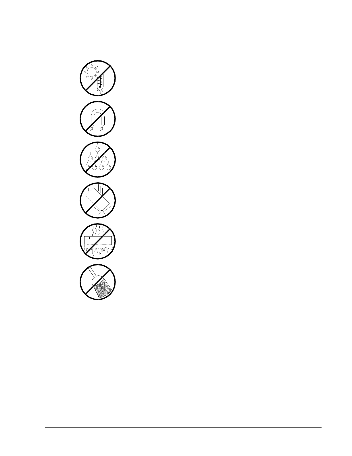
Use the following guidelines to pro p er ly handle and care for your syste m.
Protect the system from ext r em ely low or hi gh temper atures. Let
the system warm (or cool) to room temper ature before using it.
Keep the system away from magnetic forces.
Keep the system dry. Do not wash the system with a wet cloth or
pour fluid into it.
Protect the system from bei ng bum ped or dr opped.
Check the system for condensation. If condensation exi sts, allow it
to evaporate befor e poweri ng on the system.
Keep the system away from dust, sand, and dirt.
Using This Guide xv
Page 18

NEC
xvi Using This Guide
Page 19

System Overview
Overview
System Chassi s
Power Supply
Peripheral Bays
SAF-TE (SCSI Access ed Fault Tolerant Enclosure)
Board
System Board Features
Emergency Management P ort Cons ole
1
Platform Event Paging
System Securi ty
Page 20
Overview
This server is a modular, multiprocessing server based on t he Intel Pentium® II and
Pentium® III chip sets. The combination of compute performance, memory capacity,
and integrated I/O provides a high performance enviro nme nt for many server market
applications.
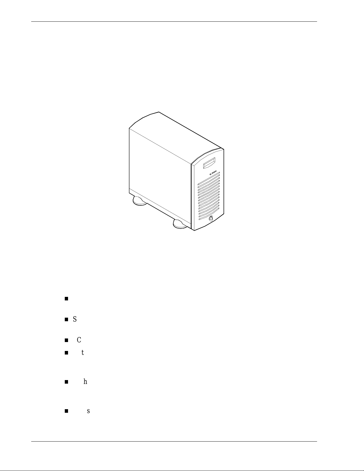
This s erve r is a ls o conveniently housed in a tow er-bas ed, as shown below.
Tower-Based System Front View
This s erve r system is d esigned for minimu m downtime. To this end , the s e rver includes
or has the options to include the following:
Optional power system redundancy; in a system configured with two power supplies,
the system will continue to operat e with a single power supp ly failure.
Self-contained power supply units that can be easily installed or removed from the
back of the chassis.
SCSI drive bays access ib le from the front of the chassis.
Hot-swap SCSI disk drive backplane; a failed drive can be removed and a new drive
installed without system power being turned off, if an optional Redundant Array of
Independ ent Disks ( RAID ) co ntro lle r is in s talled.
High degree of SCSI disk fault tolerance and advanced disk arra y management
features through the use of RAID technolog y, if an optional RAID co nt ro ller is
installed.
Chassis that supports up to two power supplies. The second power supply can be
added to provide redundant power.
1-2 System Overview
Page 21

As application requirements increase, you can expand your server with an additional
processor, additional memory, add-in boards and peripheral devices: tape devices, CDROM, diskette drives and hard disk drives.
Your server features the following major components:
Single or dual high-perfor mance processors packaged in either Single Edge Contact
Cartridge (SECC) or Single Edge Contact Cartridge 2 (SECC2) packages.
32 MB to 1 GB of memory, using up to four unbuffered DIMMs. Memory is
partitioned as four banks of SDRAM DIMMs, each providing 72 bits of
non interleaved memory (64 bit ma in me mory plus E C C ).
Four PCI (33/32 bit) expansion slots for add-in boards. Two PCI (66/32) 5V
expansion slots (backwards compatible to PCI 33/32 bit.)
One ISA expansion slot for add-in board. Embedded PC-compatible support (serial,
parallel, mouse, keyboard, diskette, and Plug and Play features).
Server Management that includes:
Thermal/voltage mo nitoring and erro r handling .
Rea l time clock /ca lendar (RTC).
Front panel controls and indicat ors (LEDs).
System Setup Utility (SSU).
Basic Input/Output System (BIOS), Power On Self Test (POST), and Setup
stored in flash memory.
Integrated onboard Cirrus Logic CL-GD5480 Super Video Graphics Array (SVGA)
controller with 2 MB of 10 ns onboard SGRAM (Synchronous Graphics Memory)
video memory.
Adaptec AIC-7896, supporting onboard Ultra2 (LVDS) Wide and Ultra-Wide SCSI
interfaces.
Integrated onboard Network Interface Contro ller (NIC), an Inte l 82559 PCI LAN
controller for 10 or 100 Mbps TX Fast Ethernet networks. RJ-45 Ethernet connector
with indicator LEDs for I/O backpanel.
Dual Cha nnel enha nced IDE controller.
Chas sis that holds up to 12 d rives: s eve n hot -swa p bays for ultra-2 (LVD) SCSI hard
drives; five removable media expansion bays with a CD-ROM reader already
installed in o ne bay; and a hal f-height bay with a diskette drive alrea dy insta lled in
the bay.
Seven hot-swap SCSI hard disk drive bays acces s ible from the front of the chassis.
The bays are secured behind a lockable front door where the drives can be swapped
in or out of the system without powering it down, if RAID is configured in the
system.
SCSI backplane is Ultra-2 (LVD) ready.
System Overview 1-3
Page 22

Integrated dual Universal Serial Bus (USB) ports.
One standard power supply module with a slot available for an additional redundant
power supply module. When an additional power supply module is installed, both
the standard and additional redundant power supply module slots become hot
swappable.
Hardware monitors (temperature, fans, and voltage) and software monitors to
indicate failure s.
Mechanical: Keylock at the front of the chassis and two metal padlocks loops (one at
the back of each side panel). Two intrusion se nso r switches for the front and lefthand side of the chassis . One interloc k sens or swit ch for the right-ha nd sid e of the
chassis.
1-4 System Overview
Page 23
System Chassis
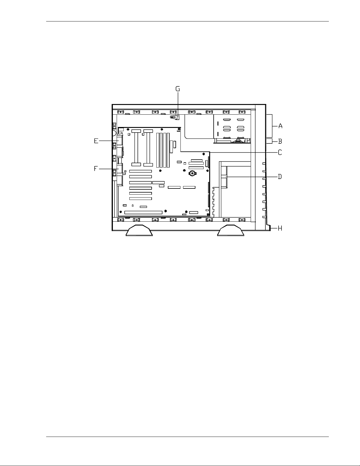
The system chassis is an easy-to-expand, fabricat ed metal struct ure. T he major s yst em
compone nts are shown in the following illustratio ns .
System Chassis (Left Side View)
A. Removable media bays (2)
B. Speaker/Switch assembly
C. System board
D. Front input fan
E. Rear exhaust fan
F. Second rear exhaust fan
G. Intrus ion switch - Side Cover
H. Intrusion keylock switch - Front Cover
System Overview 1-5
Page 24
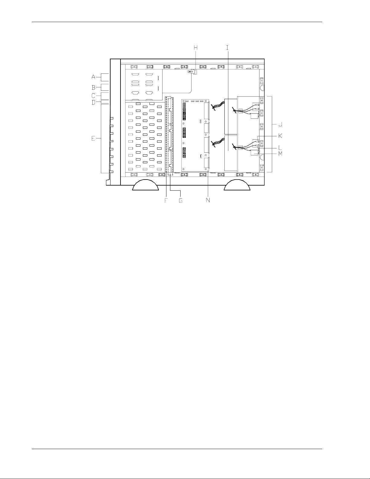
System Chassis (Right S ide View)
A. CD-ROM drive
B. Removable media bay
C. 1.44 MB 3.5"diskette drive
D. SAF-TE boar d
E. SCSI disk drive bays (7)
F. SCSI backplane board
G. Fans, behind SCSI disk drive bays (3 standard)
H. Interlock switch - side cover
I. Standard power supply
J.
K. Power supply status LED
L. DC power LED
M. Power available switch
N. Power supply distribution board
1-6 System Overview
Power supply module slots (one standard power supply slot
and one optional power supply slot)
Page 25

Power Supply
The ATX300 watt power supply is switch-selectable for 115 or 230 Vac at an operating
frequency of 50/60 Hz. It is designed to comply with existing emission standards and
provides sufficient power for a fully loaded system configuration. The power supply
voltage selection switch is factory set to 115Vac for systems used in the United States;
it is set to 230Vac for systems used in Europe.
Peripheral Bays
The system supports a variety of standard PC AT-compatible peripheral devices. The
chassis includes these peripheral bays:
A 3.5-inch front panel bay for mounting the standard 3.5" diskette drive (supports
720 KB and 1.44 MB diskette media)
Four 5.25-inch removable media
peripheral devices: standard CD ROM drive and optional tape drives, etc.
Seven hot-s wap S C SI hard disk drive bays fo r mo unting up to seven SCSI hard disk
drives in easily removable dr ive carriers.
Note:
plane that requir e an 80- pin si ngle connector attachment (SCA)
connector on the driv es that you install.
SAF-TE Board
The system has a SAF-TE ( S CSI Accessed Fault T olerant Enclosure) boar d that
provides an inter face for the d isk subs ystem to automatically integrat e with per ipheral
packaging that supports status signals, hot swapping drives, and enclosure monitoring.
The transport mechanism for the st andardized alert detection and status reporting is the
SCSI bus. Disk drives, power supplies, cooling fans, and temperature are continually
monitored and the conditions then reported over the SCSI bus to the system. When used
with RAID management software the user can be alerted of impending or imminent
disk conditions requiring attent ion. This allows the user to react to conditions that could
normally go unnoticed until data loss.
front pa nel ba ys for mounting hal f -he i ght 5.25-inch
The SCSI hard disk drive bay s cont ain a hot-swap back
System Board Features
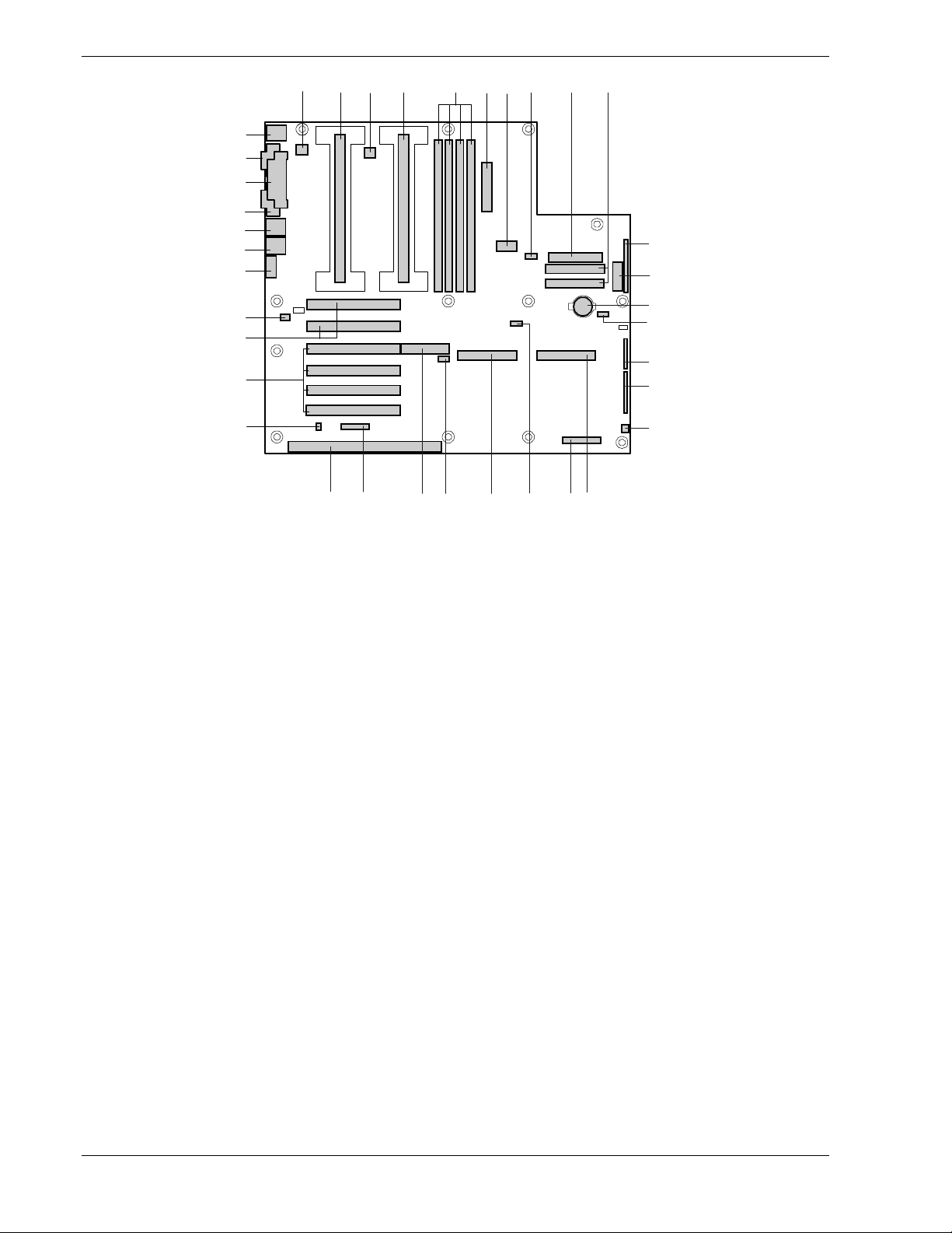
The system board offers a “flat” des ig n with the processor and memory subsyste ms
residing on the board. This figure shows the major components on the system board.
The following subsections describe the system board major components.
System Overview 1-7
Page 26
JJ
I I
HH
GG
FF
EE
DD
ABCD EGHIJ
F
K
L
CC
M
N
BB
O
AA
Z
Y
RSTUVWX
P
Q
System Board
A. Fansink connector 2 S. Server monitor module (SMM) connector
B. Secondary processor T. External Wake on LAN connector
C. Fansink connector 1 U. Ultra2/LVD SCSI connector
D. Primary processor V. Hard drive LED connector
E. DIMM slots W. Adaptec ARO-1130 connector/PCI slot 4
F. Main power connector (CAUTION: The
power plug can only be plugged into the first
20 pins of the 24-pin main power connector.)
X. Reserved
G. ATX Aux power connector Y. ISA connector
H. Fan connector FAN2A Z. Chassis intrusion connector for the front door
intrusion switch.
I. Diskette drive connector AA. PCI-33/32 connectors
J. IDE connectors BB. PCI-66/32 connectors
K. ATX front panel connector CC. Fan connector FAN2B
L. Front panel connector, 16 pin DD. Video connector
M. Lithium bac kup bat te ry EE. USB connectors
N. Reserved FF. NIC connector and LEDs
O. Jumper block GG. Serial port connector
P. Jumper block HH. Parallel port connector
Q. Fan connector 1 II. Serial port connector
R. Ultra Wide SCSI connector JJ. Mouse/keyboard connectors
1-8 System Overview
Page 27

Processors
Depending on system configuration, each system may include one or two processors.
Each processo r is packaged in either a S ingle Edge Contact Cartridge (SECC) or Single
Edge Contact Cartr idge 2 (SECC2) package. The cartr idge includes t he processor core
with an integrated 16 KB primary (L1) cache; the secondar y (L2) cache; a t her mal
plate; and a back cover. The processor implements the MMX™ technology and the
processo r ’s nu meric co pro cessor significantly increases the speed of floating-point
operations.
The processo r exte r nal interface is MP (Multi-Pro cessor) ready and operates at a
maximum of 100 MHz. The processor contains a local APIC (Advanced Programmable
Interrupt Controller) section for interrupt handling in MP and UP (Uni-Processor)
environments.
The second-level cac he is located on the substrate o f the processor cart r idge. The cache
includes burst pipelined synchronous static RAM (BSRAM). The L2 cache is offered in
512 KB configurations only, with error correcting code (ECC) that operates at half the
core clock rate.
System Memory
The system board contains four 168-pin DIMM sockets. Memory is partitioned as four
banks of SDRAM DIMMs, each pro viding 72 bits of noninterleaved memory (64-bit
main memory p lus ECC ). Your s ystem may include from 32 MB t o 1 GB of memory,
using up to four DIMMs.
System memory begins at address 0 and is continuous (flat addressing) up to the
maxi mu m amo u nt of DRAM ins t a lle d ( exc ep tion: syste m memo r y is no nc o ntigu o u s in
the ranges defined as memory holes using configuration registers). The system supports
both base (co nvention al) a nd extended me mory.
Memory should be added in order from slot 1 to slot 4.
Note:
Use DIMMS currently available from the Approved
Note:
Vendors List (AVL) only. Contact your NEC sales representative or
dealer for the curr ent AV L of mem ory modules (DI M M s) available for
your server.
System Overview 1-9
Page 28

I/O Expansion Slots
The server's expa nsio n capa bi l it ies meet t he needs of file and application servers for
high performance I/O by providing a combinat ion of PCI local bus and ISA connecto r s.
The system board has one full- lengt h IS A bus co nnect or .
The ISA features include:
Bus speed up to 8.33 MHz
16-bit memory addressing
Type A transfers at 5.33 Mbps
Type B transfers at 8 Mbps
8- or 16-bit data transfers
Plug and Play ready.
The system board has four full-length PCI (PCI-33/32 bit) connectors.
The PCI features include:
Bus speed up to 33 MHz
32-bit memory addressing
5 V signaling environment
Burst transfers of up to 133 Mbps
8-, 16-, or 32-bit data transfers
Plug and Play ready
Parity enabled.
The system board has two full-length PCI-66 universal connectors.
The PCI features include:
Bus speed up to 66 MHz
32-bit memory addressing
5 V/3.3 V signaling environment
Burst transfers of up to 266 Mbps
8-, 16-, or 32-bit data transfers
Plug and Play ready
Parity enabled.
Note:
the bus speed for both PCI-66 slots will be lowered to 33 MHz.
1-10 System Overview
If a PCI-33 card is installed into one of the PCI-66 sl ots,
Page 29

Real-Time Clock/Calendar
The Y2K compliant real-time clock pro vides system clock/c alendar information stored
in a non-volatile memory (NV RAM) . The rea l-time clock batter y prov ides power
backup for the real-time clock.
BIOS
A BIOS and Setup Utility are located in the Flash EP ROM on the system board and
include support for system setup and PCI/ISA Plug-and-Play auto-configuration. A
number of security, reliability, and manageme nt features also have been incorporated to
meet vital server needs.
IDE Controller
IDE is a 16 bit interface for intelligent disk drives with disk cont ro ller electronics
onboard. The PCI/IS A/IDE Accelerat or, also known as PIIX4e, is a multifunction
device on the server board that acts as a PCI based Fast IDE controller. The device
controls:
PIO and IDE DMA/bus master operations
Mod e 4 timin gs
Transfer rat es up to 33 MB/s
Buffering for PCI/IDE burst transfers
Master/slave IDE mode
Up to two devices per channel; two channels, IDE0 and IDE1
The IDE controller provides support for the internally mounted CD-ROM and an
optional tape device.
Network Controller
The system board includes a 10BASE-T/100BASE-TX network controller based on the
Intel 82559 single chip Fast Ethernet PCI Bus Controller. As a PCI bus master, the
controller can burst data at up to 132 MB/sec. The cont ro ller cont ains t wo rece ive and
transmit FIFO buffers that prevent data overr uns or underruns while wait ing for access
to the PCI bus. The cont roller has the following:
32-bit PCI bus master inter face (direct drive of bus), compat ible with PCI B u s
Specification, R evisi on 2.1
Chained memory structure with improved dynamic transmit chaining for
enhanced performance
Progra mmable transmit threshold for improve d bus util ization
Early receive interrupt for concurrent pro cess ing of receive dat a
On-chip counters for network management
System Overview 1-11
Page 30

Autodetect and autoswitching for 10 or 100 Mbps network speeds
Support for both 10 Mbps and 100 Mbps networks, capable of full or half
duplex, with back-to-back transmit at 100 Mbps.
The network status LEDs on the syste m board, which are visible from the rear of the
chassis indicate:
Transmit/rece ive act ivit y on t he LAN
Valid lin k t o the LAN
10/100 Mbps transfer mode.
SCSI Controller
The system board includes an embedded Adaptec AIC-7896 dual function SCSI
controller. The Adaptec AIC-7896 contains one independent Ultra2 (LVD) wide and
one Ultra wide SCSI interface that share a single PCI bus mast er co nt roller.
No logic, termination, o r r esist or loads are r equired to connect devices t o the SCSI
controller, other than ter minat ion in the device at the end of the cable. This syste m can
be cabled from either of the two onboard SCSI interfaces to t he SCSI backp lane o n t he
rear of the hot swap chassis were t er mination is provided on the SAF-TE board.
Video Controller
The system has a high-performance SVGA subsystem that supports the following:
BIOS compatibility with VGA, EGA, CGA, Hercules Graphics, and MDA
2 MB of Video Random Access Memory (VRAM) video buffer
16-bit bus for high-speed displa y memor y access
Hardware accelerated bit block transfers ( BIT BLT )
Display powe r management system
Supports 72Hz refresh, non-interlaced at: 640x480, 800x600, 1024x768, or
1280x1024 resolutions
Displays of up to 16M colors at 640x480 and 800x600 resolutions, 64K colors at
1024x768 resolutions and 256 colors at 1280x1024 resolutions.
1-12 System Overview
Page 31

Peripher al C o ntroller
The advanced integrated peripheral contro ller supports two serial ports, one parallel
port, diskette drive, PS/2-compatible keyboard and mouse, and integrat ed Real Time
Clock (RTC). The system provides the connector interface for each port.
Serial Ports
Both serial ports ar e relocat able. E ach serial port can be set to one of four different
COM ports and can be enabled separately. When disabled, serial port interrupts are
available to add-in boards.
Parallel Port
One IEEE 1284-compatible 25-pin bidirectional EPP (supporting levels 1.7 and 1.9)
parallel port is pro vided. B IOS progr a mming enable s the pa rallel po rt and determines
the port address and interrupt. When disabled, the interrupt is available to add-in
boards.
Keybo ar d an d Mo us e
The keyboard/mouse cont ro ller is PS/2-co mpat ible. The ser ver may be locked
automatically if there is no keyboard or mouse activity for a predefined length of time,
if specified through the System Setup Utility (SSU). Once the inactivity (lockout) timer
has expired, the keyboard and mouse do not respond until the previously stored
password is entered.
ACPI
The server supports the Advanced Configurat ion and Power Int er face (ACPI) as
defined by the ACPI 1.0 and PC97 specifications. An ACPI aware oper at ing system can
put the system into a stat e where the hard drives spin down, the system fans sto p, and
all processing is halted. However, the power supply will still be on and the processors
wil l s till be dissipating s ome p ower, so the power supply fan and processor fans will
still run.
The system power is off only when the AC power cords are
disconnected from the back of the chassis.
External Device Connectors
The external I/O connectors provide support for a PS/2 compatible mouse and a
keyboard, connectors for VGA monitor, 2 serial port connectors, a parallel port
connector and two US B connect ions.
!
CAUTION
System Overview 1-13
Page 32

System Board Management Controller (BMC)
All se rver mana gement functionality is concentra ted in the S ys te m Board Management
Controller (BMC). The BMC and associated circuit r y are power ed from a 5Vdc standb y
voltage, which remains active when system power is switched o ff, but t he ac power
source is still on and connected.
One m ajor func tion of the BMC is to auto no mous ly monitor s ystem mana gement
events, and log their occurrence in the nonvolatile Syst em Event Log (SEL). These
include events such as overtemperatur e and o vervoltage co nd it ions, Baseboard fan
failure, or chassis intrusion via the front door. To enable accurate monitoring, the BMC
maintain s the nonvolat ile Se ns or D a ta Rec ord (SDR), fro m wh ich senso r information
can be retrieved. The BMC pr ovides an ISA host interface to SDR sensor informat ion,
so software running on the server can poll and retrieve the server's current status.
SEL contents can be retrieved after system failure, for analysis by field service
personnel using server management software tools such as Intel Server Control
available on the CD-ROM that ships with your system.
The BMC does the following:
Monitors server boar d temperat ur e and voltage
Monitors processor presence and contro ls FRB
Detects and indicates baseboard fan failure
Manages t he SE L interface
Monitors the system man agemen t w atchdog time r
Monitors the periodic SMI timer
Mana ges front panel NMI handlin g
Monitors the event r eceiver
Manages the IS A ho st and I MB interface
Controls secure mode, including video blanking, floppy write-protect monitor ing,
and front panel lock/unlock initiation
Manages the senso r event initialization agent
The BMC supports the Emergency Management Port (EMP) Console, which allows
remote server management via a modem or direct connect ion to a manager system.
Events monitored by the manager system include over-temperature and over-voltage
conditions, fan failure, or chassis intrusion.
1-14 System Overview
Page 33

Emergency Management Port Console
The Emergency Management P o rt (E MP ) Co nsole prov ides an inter face to the
Emergency Management Port (EMP). This interface allows re mot e ser ver management
via a modem or direct (serial port to serial port) connect ion.
The server cont ro l oper ations availa ble w ith EMP Co nsole are:
Connecting to remot e servers
Powering the server on or off
Resetting the server
The EMP Console uses three management plug-ins to monitor the server:
SEL Viewer
SDR Viewer
FRU Viewer
The EMP Console also has Pho nebo ok plug-in that can be used to create and maintain a
list of servers and their pho ne number s.
EMP and PEP (Platform Event Paging) share your m odem .
Note:
PEP has priority over all applications except EMP. If an alert occurs,
PEP will reset your modem and page you.
Informatio n on t he Emerg ency M anagement Port (EMP) Console may be fo und in
Appendix C of t his Use r’s G uide .
Platform Event Paging
With Platform Event Paging (PEP), your server can be configured to auto maticall y dial
up a paging service and page you when a platform event occurs. Platform events
include temperature out-of-ra nge, voltage out-of-range, chassis intrusio n, fan failure,
etc.
If PEP is enabled and the BMC receives or detects a new event, it automatically sends a
page. It can send a page if the processor s are down or if the system so ftwar e is
unavailable.
PEP needs an external modem connect ed to the server 's EMP ( E mergenc y Management
Port) serial connection. This is typically the COM2 serial connect or.
System Overview 1-15
Page 34

System Security
To help prevent unauthor ized entr y or use of the syste m, the syst em includes a full
lockable front panel and Server Management software that monitors the system
intrusion sw itch.
Security with Mechanical Locks and Monitoring
The front panel of the tower- based syst em contains a mechanical lock to prevent access
to the front of the computer chassis. I n add it ion, eac h side cover contains a padlock
loop (padlock not provided) located o n the rear of the chassis to prevent remova l o f the
side covers and access to t he inside of the computer chass is
The computer chassis includes a n intr usion switch for the left side cover, the front cover
keylock, and an interlock switch for the right-side cover (as viewed from the front).
When the front cover is unlocked, the switch transmits an alarm signal to the syste m
board, where BMC firmware and server management softwar e pro cesses the signal. The
left side cover when open tr ansmits an alarm signal to the SAF-TE board, which
processes the signal so that t he ES MPRO Management software may set an a larm. The
right side cover act ivates an interlock switch controlling power shut down to the system
for safe ty rea so ns.
Software Locks
The BIOS Setup Utility and the Syste m Setup Utility (SSU) pro vide a number of
security features to prevent unaut ho r ized or accidental access to the system. Once the
security measures are enab led, acces s t o the system is allowed only after t he user enter s
the correct password(s). For example:
Enable the keyboard lockout timer so t hat the server requ ires a passwor d to
reactivate the keyboard and mouse after a specified time-out period1 to 120
minutes.
Set and enable an administrative password.
Set and enable a user password
Set secure mode to prevent keyboard or mouse input and to prevent use of the
front panel reset and power switches.
Activate a hot-key combinat ion to ent er secure mode qu ickly.
Disable writing to the diskette drive when secure mode is set.
Disable access to t he boot sector o f the operating system hard disk drive.
1-16 System Overview
Page 35

Using Passwords
You can set either the user password, the administrator password, or both passwords.
Note:
password. If user password is set and administrator password is
cleared, user can lock out administrator. If user password is set,
administrator cannot lockout user.
If only the user password is set, you:
Must enter the user password to enter BIOS Setup or the SSU.
Must enter the user password to boot the server if Password on Boot is enabled in
either the BIOS Setup or SSU.
Must enter the user password to exit secure mode.
If only the administrator password is set, you:
Must enter the administrator password to enter BIOS Setup or the SSU.
Must enter the administrat or password to boot the server if Passwor d on Boot is
enabled in either the BIOS Setup or SSU.
Must enter the administrat or password to exit secure mode.
Administrator can not di sabl e or change t he user
If both passwords are set, you:
May enter the user password to enter BIOS Setup or the SSU. However, you will not
be able to change many of the options.
Must enter the administrator password if you want to enter BIOS Setup or the SSU
and have access to all of the o pt ions.
May enter either password to boot the server if Password on Boot is enabled in either
the BIOS Setup or SSU.
May enter either passwo r d to exit secure mode.
Secure Mode
Configure and enable the secure boot mode by using the SSU. When secure mode is in
effect:
You can boot the server and the operating system will run, but you must enter t he
user password to use the keyboard or mouse.
You cannot turn off system power or reset the server from the front panel switches.
Secure mode has no effect on funct ions enabled via t he Server Manager Module
(e.g. EMP) or power control via the real time clock.
Taking the server out of secure mode do es not change t he st at e of system power. That
is, if you press and release the po wer switch while secure mode is in effect, the syst em
wil l not be po were d off when sec ure mode is later remove d. Howe ver, if the front pa nel
power switch remains depressed when secure mode is removed, the server will be
powered off.
System Overview 1-17
Page 36

Summary of Software Security Featu res
Table 1-1 below lists the software secur it y features and describe s what prot ect ion each
offers. In general, to enable or set the features listed here, you must r un t he SSU and go
to the Security Subsystem Group, menu. The table also refers to other SSU menus and
to the Setup utility.
Table 1-1. Software Security Features
Feature Description
Secure mode
Disable writ in g to dis kette
Disable the power and
reset buttons
Set a time out period so
that keyboard and mouse
input are not accepted
Also, screen can be
blanked, and writes to
diskette can be inhibited
How to enter secure mode:
• Setting and enabling passwords automatically places the system in
secure mode.
• If you set a hot-key combination (through the SSU or Setup), you can
secure the system simply by pressing the key combination. This
means you do not have to wait for the inactivity time-out period.
When the system is in secure mode:
The server can boot and run the operating system, but mouse and keyboard
input is not accepted until the user password is entered.
At boot time, if a CD is detected in the CD-ROM drive or a diskette in drive A, the
system prompts for a password. When the password is entered, the server
boots from CD or diskette and disables the secure mode.
If there is no CD in the CD-ROM drive or diskette in drive A, the server boots
from drive C and automatically goes into secure mode. All enabled secure mode
features go into effect at boot time.
To leave secure mode: Enter the correct password(s).
In secure mode, the ser ver will not b o ot from or write to a diskette unless a
password is entered. To set this feature, use the SSU Security Subsystem
Group.
To write protect access to diskette whether the server is in secure mode or not,
use the Setup main menu, Floppy Options, and specify Floppy Access as read
only.
Enable the feature through the SSU. Then the power and reset buttons are
disabled when the server is in secure mode.
Specify and enable an inactivity time out period of from 1 to 120 minutes.
If no keyboard or mouse action occurs for the specified period, attempted
keyboard and mouse input will not be accepted.
The monitor display will go blank, and the diskette drive will be write protected (if
these security features are enabled through Setup or the SSU).
To resume activity: Enter the correct password(s).
Control access to using
the SSU: set
administr at iv e pass word
1-18 System Overview
To control access to setting or changing the system configuration, set an
administrative password and enable it through Setup or the SSU.
If both the administrative and user passwords are enabled, either can be used to
boot the server or enable the keyboard and/or mouse, but only the administrative
password will allow Setup and the SSU to be changed.
To disable a password, change it to a blank entry or press CTRL-D in the
Change Password menu of the Administrative Password Option menu found in
the Security Subsystem Group.
To clear the password if you cannot access Setup or the SSU, change the Clear
Password jumper (see Chapter 3).
Page 37

Table 1-1. Software Security Features (continued)
Feature Description
Control access to the
system other than SSU:
set user password
Boot without keyboard
Specify the boot sequence The sequence that you specify on the menu in the SSU MultiBoot Group will
To control access to using the system, set a user password and enable it
through Setup or the SSU.
To disable a password, change it to a blank entry or press CTRL-D in the
Change Password menu of the User Password Option menu found in the
Security Subsystem Group .
To clear the password if you cannot access Setup or the SSU, change the Clear
Password jumper (see Chapter 3).
The system can boot with or without a keyboard. During POST, before the
system completes the boot sequence, the BIOS automatically detects and tests
the keyboard if it is present and displays a message. There is no entry in the
SSU to enable or disable a keyboard.
determine the boot order. If secure mode is enabled (a user password is set),
then you will be prompted for a password before the server fully boots. If secur e
mode is enabled and the “Secure Boot Mode” option is also enabled, the server
will fully boot but will require a password before accepting any keyboard or
mouse input.
System Overview 1-19
Page 38

1-20 System Overview
Page 39

Setting Up the System
Overview
Selecting a Site
Unpacking the System
Getting Familiar with the System
Making Connections
Setting the Line Voltage
Connecting the Power Cord(s)
Powering On Your System
2
Page 40
Overview
This chapter describes how to select a site, unpack the system, make cable
connections, and power on the tower-based system unit.
Selecting a Site
The system operates r eliably in a t ypical o ffice en vironme nt .
Choose a site that is:
Near grounded, three-pronged power outlets.
Note
NEMA 5-15R outlets for 100-120 VAC or NEMA 6-15R
outlets for 200- 240 V A C. For ot her i nternational sites, this
means three-pronged power outlets applicable for the
electrical c ode of t he r egion.
Be sure the power service connec tion is through a properly
grounded outlet.
When two power supplies are installed in the system the
power plug from each of the power suppli es must be
plugged into the sam e common gr ound power outlets.
Clean, dust-free, and well ventilated. Front and rear ventilating openings
For the United States and Canada, this means a
:
!
WARNING
!
CAUTION
kept free of obstruct ions. Away fro m sour ces of heat, vibration or
physical shock.
Isolated from strong electromagnetic fields and electrical noise produced
by electrical devices (such as air conditio ners, large fans, large electric
motors, radio and TV transmitters, and high-frequency security devices)
Spacious enough to provide at least five inches (13 centimeters) behind
the system and three inches (eight centimeters) on each side of the system
for proper cooling, airflow, and cable clearance.
Easily accessible for syste m maintenance and installation of system
upgrades.
2-2 Se tting Up the System
Page 41

Unpacking the System
!
WARNING
Your system weighs approximately 65 pounds (29.25 kg). If
your system contains numerous optional boards and
peripheral dev ic es, it will weigh more. To avoid personal
injury, make sure you have someone help you lift or move
the system.
When you receive your system, inspect the shipping co ntainers prior to
unpacking. If the shipping boxes are damaged, note the damage, and if possible,
photograph it for reference. After re moving the cont ent s of the containers, keep
the cartons and the packing materials. If the cont ent s appear damaged when you
unpack the boxes, file a damage claim with the carrier immediately.
Getting Familiar with the System
Before setting up your system, you should become familiar with the system’s
features, such as the locat ion of your syst em's front and rear panel switches,
indicator s and connector s, etc.
Setting Up the System 2-3
Page 42
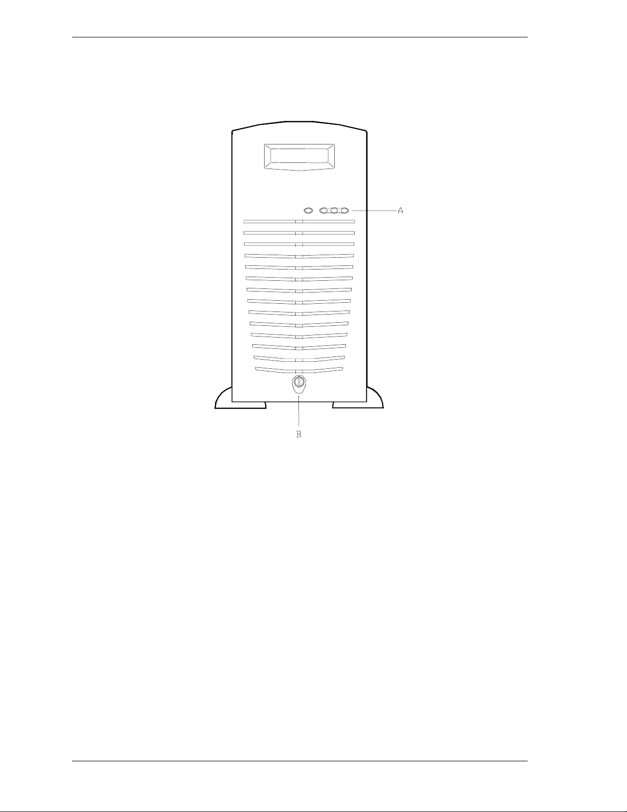
Front View with Front Door Closed
This figure shows t he location of the front system features.
A. System indicators ( See "Front View with Front Door
B. Keylock When locked, secures the front door
2-4 Se tting Up the System
Front Features
Opened" later in this chapter).
not allowing access to the front system
controls.
Page 43
Front View with Front Door Opened
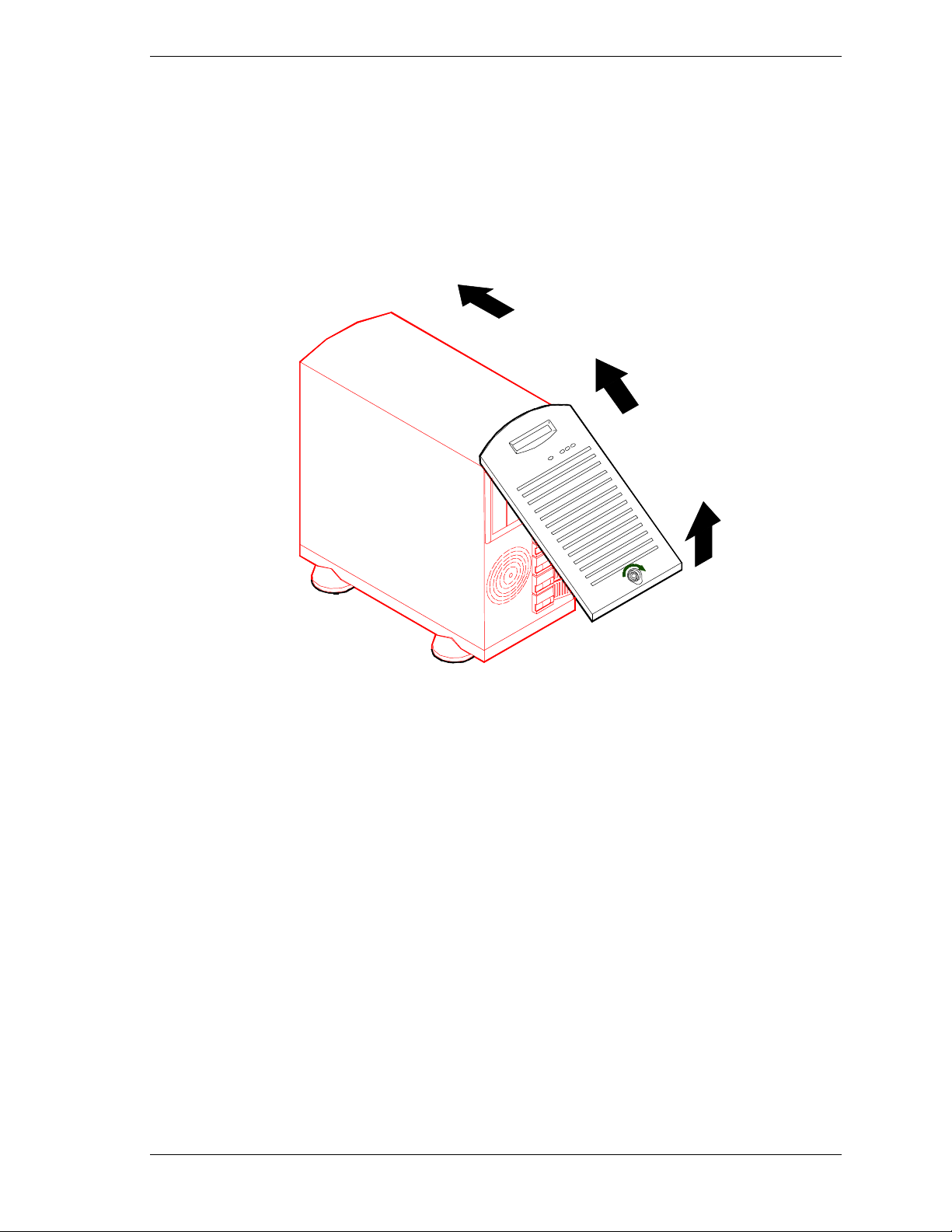
Refer to the following figure and open the front door of the cabinet as follows:
1. If door is locked, unlock the front door.
2. Pull the bottom of the front door out and tilt up until it is aligned level with
the top of the cabinet, then push the door back directly over the top of the
cabinet as far as it will go.
Opening the Front Door
Setting Up the System 2-5
Page 44
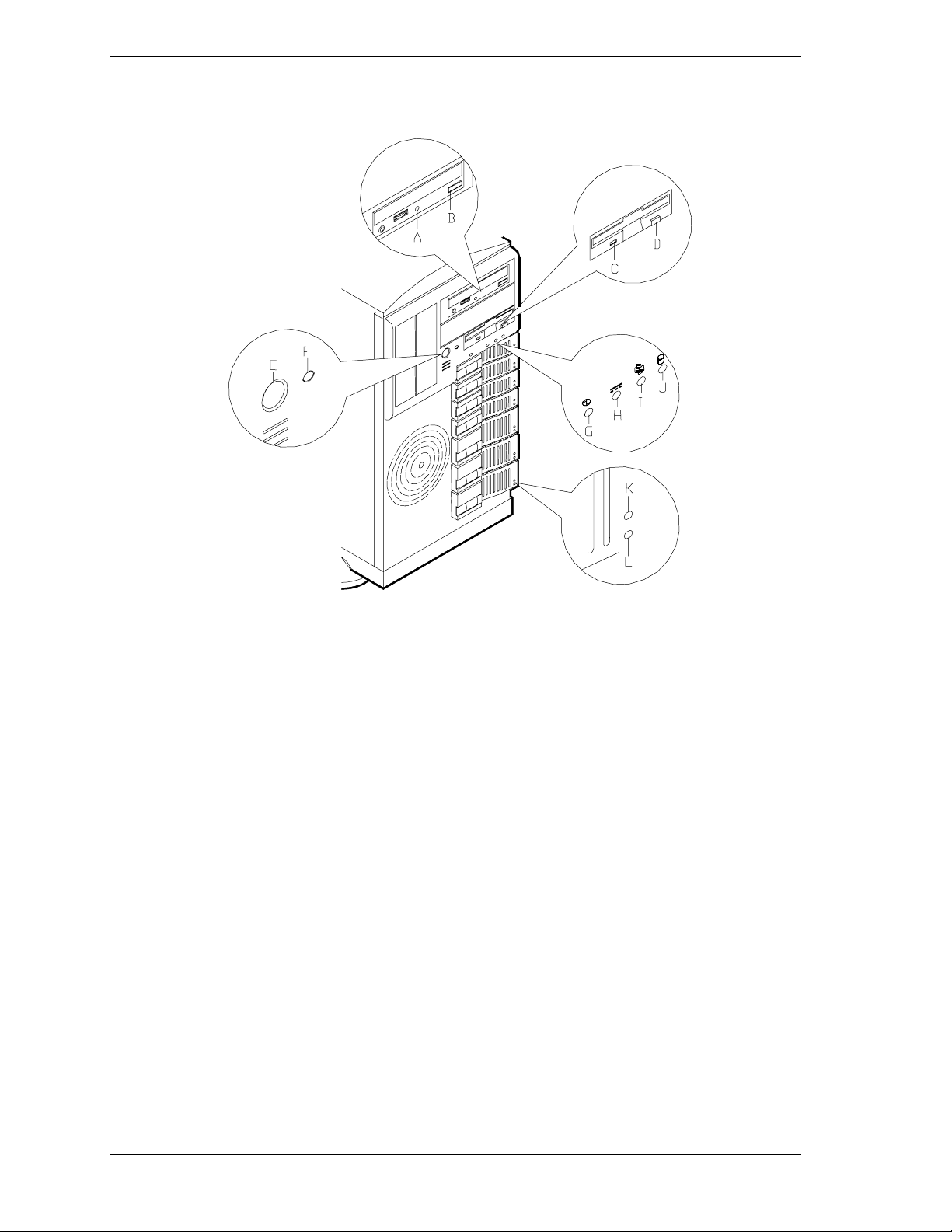
This figure shows t he location of the front system controls and indicato r s.
Front System Features and Controls
A. Activity light, CD-ROM reader When lit, CD-ROM reader i s in use.
B. Load/eject butt on, CD-ROM reader Press to load CD and eject CD.
C. Activity light, 3 ½-inch diskette drive When lit, disket te is in use.
D. Ej ec t but ton, 3 ½-inch diskette drive Pr ess to ej ec t diskette.
E. DC power ON/OFF switch Press to turn system DC power on or off.
F. Reset switch Press to reinitialize system.
G. DC power ON/OFF See table "Front System Status Indicator
LEDs" that foll ow.
H. Power alarm
I. Fan al arm
J. Array alarm
K. Disk drive activity LED See table "Disk Driv e Status Indicator
L. Disk drive status LED See table "Disk Driv e Status Indicator
See table "Front System Status Indicator
LEDs" that foll ow.
See table "Front System Status Indicator
LEDs" that foll ow.
See table "Front System Status Indicator
LEDs" that foll ow.
LEDs" that foll ow.
LEDs" that foll ow.
2-6 Se tting Up the System
Page 45
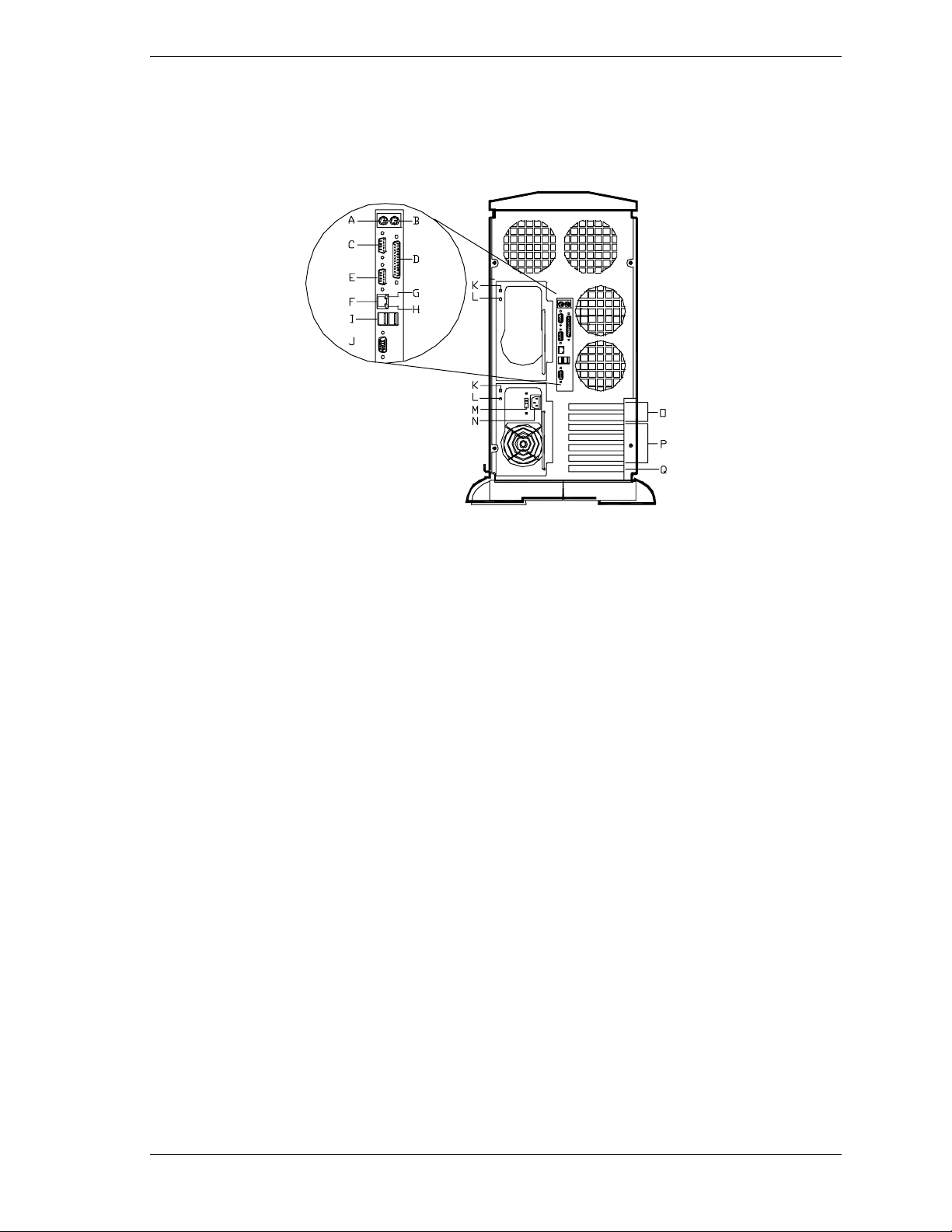
Rear View
This figure shows t he location of the fo llowing rear s yst em features and
controls.
Rear Features and Controls
A. Keyboard PS/2-compatible 6-pin mini-D IN conne cto r.
B. Mouse PS/2-compatible 6-pin mini-D IN conne cto r.
C. COM1 COM1 serial port 9-pin connector.
D. Printer 25-pin parallel port connector.
E. COM2 COM2 serial port 9-pin connector.
F. LAN connector RJ-45 connector.
G. Gr een LAN status light See Table "LAN Status Indicator LEDs (I/O Panel)" that follows.
H. Orange LAN status light See Table "LAN Status Indicator LEDs (I/O Panel)" that follows.
I. USB connectors Two USB connectors
J. VGA VGA monitor 15-pin connecto r.
K. Power supply status
(green light)
L. DC power status (amber light) See Table "Power Supply Status Indicator LEDs (Rear Panel)" that follows.
M. Line voltage selector switch Selects AC input power of 115 VAC or 230 VAC.
N. AC input power connector Supplies AC power to the power supply.
See Table "Power Supply Status Indicator LEDs (Rear Panel)" that follows.
O. PCI slots Two PCI-66/32 add-in board slot locations.
P. PCI slots Four PCI-33/32 add-in board slot locations.
Q. ISA slot One ISA add-in board slot locations.
Setting Up the System 2-7
Page 46

Status In di cat or LE D Descr iptions
The following tables list the System Status Indicator LEDs, the Disk Drive
Status Indicator LEDs, the Disk Drive Status Abnormal Conditions, the Power
Supply Status Indicator LEDs, and the LAN Status Indicator LEDs along with a
description of each LED indicator.
Note:
The Power Alarm, Fan Alarm, and the Array
Alarm Status Indic ator LEDs are active only when a RAID
board is installed or server management software is in use.
Front System Status Indicator LEDs
LED Status Description Response
DC Power ON/OFF Off DC power OFF None required (norma l)
ON (Green) DC power ON None required (normal)
Power Alarm Off Not active None required (normal)
ON (Amber) Failure has occurred in one or more
power supplies (see the "Power Supply
Status I ndicator s" ta ble DC Power Status
"Amber" that follows.)
Fan Alarm Off All fans operating normally None required (normal)
ON (Amber ) Fan failure Replace fan i n chassis or
replace power supply
Array Alarm O ff Always OFF unless RAID is installed None required (normal)
ON ( Amber ) R AID Arra y f ail ure Replace dis k drive with
amber light lite
Power Supply Status Indicator LEDs (Rear Panel)
LED Status Description Response
Power Supply Status Off AC Power not available None required (normal)
ON (Green) AC Power supplied to power supply None required (normal)
DC Power Status Off No alarms None required (normal)
(Amber) AC Power disc onnected, power supply
failed, or power supply not installed.
Verify AC power is ON,
reconnect AC power, or
replace power supply,
2-8 Se tting Up the System
Page 47

Disk Drive Status Indicator LEDs
LED Status Description Response
Disk Drive Activity Off Not accessing disk drive None required (normal)
ON (Green) Accessing disk drive None required (normal)
Disk Drive Status Off No alarms None required (normal)
ON ( Amber ) (See t he "Di sk Dr i ve St atus Condi t ion s"
table that follow s.)
Note: The Disk Drive Status Indicator
LEDs are active only when a RAID board
is installed.
Disk Drive Status Conditions
Condition LED
No Error Off
Faulty or Rebuild Stopped Steady ON
Rebuild Slow Blink for approximately one second
Identify Fast Blink for approximately three seconds
Predicted Fault Four fast blinks, pause (repeats)
Hot Spare Two fast blinks, pause (repeats)
LAN Status Indicator LEDs (I/O Panel)
LED Status When On When Blinking When Off
LAN Link Status Green N/A
LAN Speed Status Orange
100 Mbps network
connection
Linked to network,
sending or
receivi ng data
None
N/A
10 Mbps network
connection
Setting Up the System 2-9
Page 48

Making Connections
If your system normally operates without a video display or keyboard (for
example, as a networ k server), you must install a video display and keyboard to
configure the system. You may remove them after running the System Setup
Utility (SSU). For information on running the SSU, refer to Appendix B of this
User’s Guide.
Refer to the previous figure (Rear Features and Co nt ro ls) and connect your
keyboard, monitor, and mouse. Co nnect any external per ipheral devices such as
a printer or modem by following the instructions included with these devices.
!
Damage to the system may resul t if the k ey boar d/mouse
cable is inserted or rem ov ed when power i s appl ied to the
system.
Inserting a telephone line connector into a LAN board RJ- 45
port may result in personal injury and equipment damage.
CAUTION
2-10 Setting Up the System
Page 49
Setting the Line Voltage
The system contains an ATX300 watt power supply that is switch-selectable for
115 or 230 VAC at an operating frequency of 50/60Hz. The power supply
voltage selection switch is factory set to 115Vac for systems shipped to North
America; it is set to 230Vac for systems shipped in Europe. Line source voltages
between 200 and 240 VAC are acceptable when the power supply input voltage
is set to 230 VAC.
!
CAUTION
Before you plug the system power cord into an AC outlet,
ensure the input li ne v oltage setting for the power supply is
correct.
To use the system with line source voltages between 200
and 240 VAC, the line volt age sel ec tor switch on the power
supply must be set to 230. If you set the switc h to the 115
VAC position, t he power supply will be damaged when you
plug in your system.
When two power supplies are installed in the system both
power supplies must have their line voltage selector switc h
set to the same voltage.
If you need to change the line voltage setting, perfor m the following steps.
Note:
the power cord will not be connected to the rear panel of
your system.
1.
Unplug the AC power cord from the back of the chassis.
2.
Insert the tip of a small screwdriver or ballpoint pen into the depression on
If you are setting up your system f or the first time,
the line voltage se lector.
3.
Slide the selector switch to the left for 115 VAC or to the right for 230 VAC
(line source voltage range: 220 to 240 VAC).
Setting Up the System 2-11
Page 50
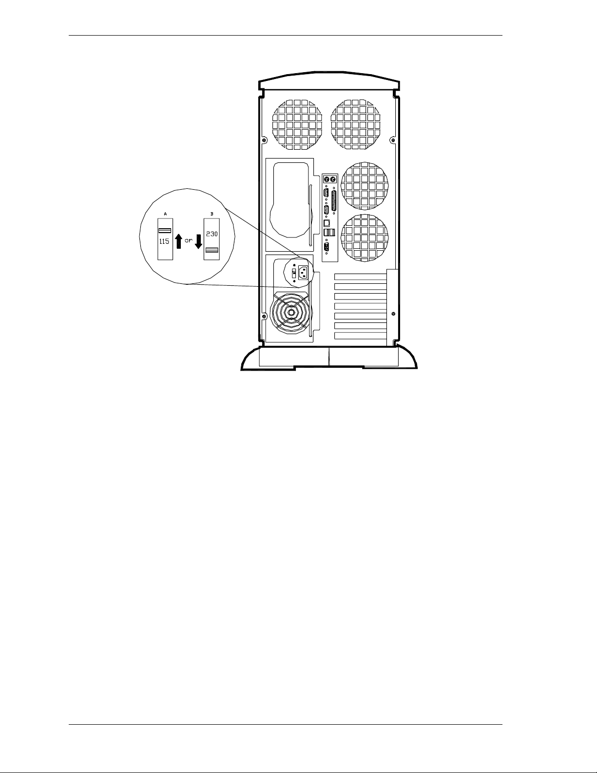
Setting the Line Voltage
A. Voltage selec tor switch set to 115 VAC
B. Voltage selec tor switch set to 230 VAC
2-12 Setting Up the System
Page 51

Connecting the Power Cord(s)
Plug the female end of the AC power cord into the input receptacle on the rear
of the power supply cage. Plug the male end of the power cord into NEMA 515R outlet for 100-120 VAC or NEMA 6-15R outlet for 200-240 VAC.
If the power cord(s) supplied with the syste m are not compatible with the AC
wall out le t in yo ur region, obt a in a suitable po w er co rd that meets the following
criteria.
The power cord must be rated for the available AC voltage and have a
current rating that is at least 125% of the current rat ing of the system.
The power cord connector that plugs into the wall outlet must be
terminated in a grounding-type male plug designed for use in your region.
It must have certification marks showing certification by an agency
acceptable in your region.
The power cord connector t hat plugs into the syst em must be a n IEC-
type CEE-22 female connector.
The power cord must be less than 1.8 meters (6.0 feet) long.
!
WARNING
Your system shipped with a power cord for each power
supply. Do not attempt t o m odify or use the suppl ied AC
power cord if it is not the exact t y pe requi r ed.
!
CAUTION
When two power supplies are installed in the system the
power plug from each of the power suppli es must be
plugged into the sam e common gr ound power outlets.
Powering On Your System
Power o n you r system as follows.
1.
Make sure all external devices, such as a video display, keyboard, and
mouse (optional) have been connected, and t he power cor ds are connected.
2.
Power on the video display and any other external devices.
3.
Press the push-button power on/off switch on the front panel. Verify that the
system power-o n LED is lit. If it is not lit, ensure t he ac power cor ds ar e
connected to a functional ac power source.
Setting Up the System 2-13
Page 52
After a few seconds your s yst em begins the internal Power- On Se lf Test s
(PO ST). PO ST auto maticall y c heck s the system bo ard, CPU module, memory,
keyboard, and most installed peripheral devices.
!
CAUTION
Always allow POST to complet e before powering down your
system.
!
CAUTION
The server management logic on your system board
monitors and logs system v oltage changes. When powering
down your system you may experience a 1–5 second delay
from the time you press the push-butt on power on/off switch
on the front panel and your system poweri ng down. T his is
normal system operation and is required by the server
management logic.
If you have problems powering on your s yste m, refer to Problem Solving in
Chapter 5 of this User’s Guide.
After you have successfully powered on your system, refer to "Configuring
Your System" in Chapter 3 of this User's Guide.
2-14 Setting Up the System
Page 53

Configuring Your System
Configuring Your System
Hot Keys
BIOS Setup Utility
Adaptec SCSI Utility
Installing Video Drivers
Configuring Syst em B oard Jum pers
3
Page 54

Configuring Your System
Configuration and setup utilities are used to change your system configuration.
You can configure your system, as well as option boards you may add to your
system, using the BIOS Setup Utility. Several unique system parameters are
configured using the BIOS Setup, which is stored in the system FLASH
memory.
You can also configure your system, including reserving resources required by
the option boards, using the System Setup Utility (SSU). Also, the SSU is used
to read stored system event information. Infor mat ion on the SSU may be found
in Appendix B of this User’s Guide.
The Adaptec Configuration Utility detects the SCSI host adapt er s on t he syste m
board. U s e this utilit y if you need to configure the two SC SI contro lle rs in yo ur
system or to perform a SCSI disk format or verify disk operation on the SCSI
disk drives.
If your system has been factory configured, the SSU, BIOS Setup, or Adaptec
Configuration Utility do not need to be run unles s you want to change the
password or security features, add certain types of option boards or devices, or
upgrade your system board.
This chapter also pro v ides information on several system configuration
parameters that ar e set by jumpers on t he syst em board. However, these
parameters do not usually require change.
Use the CD-ROM shipped with your system to create the device driver and SSU
diskett e s.
Hot Keys
For Hot keys use the keyboard’s numer ic pad to ent er nu mbers and symbols.
See Hot Keys table below.
Hot Keys
To do this: Press these keys
Clear memory and reload the operating
systemthis is a system reset.
Secure your syst em immediately. Ctrl+Alt+hotkey (Set your hot key combination with the
Ctrl+Alt+Del
SSU or Setup.)
3-2 Configuring Y our System
Page 55

BIOS Setup Utility
The BIOS Setup Utility is used to change system configuration parameters. This
utility has some unique parameters and many parameters that are also
configurable with the SSU. The utility is resident in the system FLASH memory
and does not require a diskette or an operating syste m present to run. However,
parameters set with the BIOS Setup Utility that can also be set with the SSU,
will be overwritten by the SSU the next time the SSU is run.
Using the BIOS Setup Utility
You access the BIOS Set up utility when you tur n on or reboot your system. To
run the BIOS Setup Utility, perform the following procedure:
1. Po w er-on or reboo t t he s ystem. “Press F2 t o enter SET U P ” displays.
2. Press F2. The BIOS Setup Utility starts and the Main Menu is displayed.
The menu bar at the top of the Main Menu lists the following selections:
Menu Use
Main Use this menu for basic system conf iguration.
Adv anced Use this menu for set ting the Advanced Featur es available on
your system.
Security Use this menu to set User and Supervisor Passwords and the
Backup and Virus-Check reminders.
Server Use this menu for configuring Serv er Management features.
Boot Use this menu to configure Boot Device priority.
Exit Exits the current menu.
Use the arrow keys to select a menu or an ite m on a displayed menu. Press
the value keys (listed in the table below) to cycle through the allowable
values for the selected field. Use the Exit menu’s “Save Values” select ion to
save the c urr e nt va lues on all the menus.
To display a submenu, posit ion the curso r on a selection that has a submenu
and press ENTER. An arrow precedes selections with submenus.
Refer to the following table for informat ion on the keys that you use with
BIOS Setup. These keys are also listed at t he bottom of the Setup menu.
Configuring Your System 3-3
Page 56

Key Function in Setup Menu
F1 or Alt-H Get Help about an item.
ESC Exit the current menu and return to the previo us men u.
Left or right ar r ow keys Move between menus.
Up or down arrow keys Move cur sor up and dow n. The curs or moves onl y to the
settings that you can change.
+/-
HOM E or END Mov e cur sor to top or bottom of window .
PAGE UP or PAGE DOWN Move cursor to next or previous page.
F9 Load default configuration values f or this menu.
F10 Save configuration values and exi t.
ENTER
Change the value of an i t em.
Exec ute c ommand or S elect ➨ su bmenu.
BIOS Setup Configuration Settings
The BIOS Setup Configurations tables show the default settings for the BIOS
Setup Utility and provides a place for you to recor d any changes you make to
these settings. Recommended values are bold in the fo llo w ing t ab le s.
3-4 Configuring Y our System
Page 57

Main Menu
Feature Choices Description Your Setting
System Time HH:MM:SS Sets the system time.
System Date MM/DD/YYYY Sets the system date.
Legacy Diskette A: Disabled
360KB
1.2 MB
720KB
1.44/1.25 MB
2.88 MB
Legacy Diskette B: Disabled
360KB
1.2 MB
720KB
1.44/1.25 MB
2.88 MB
Pri mary IDE Ma ster Press ENTER Refer to “Primary IDE Master
Primary IDE Slave Press ENTER Refer to “Primary IDE Master
Secondary IDE Master Press ENTER Refer to “Secondary IDE
Secondary IDE Slave Press ENTER Refer to “Secondary IDE
Keyboard Features Press ENTER Refer to “Keyboard
Memory C ach e Enabled
Disabled
Selects the di skette type.
Selects the di skette type.
and Slave Submenu.”
and Slave Submenu.”
Master and Sl ave Submenu.”
Master and Sl ave Submenu.”
Submenu.”
Enables processor cache.
CPU Speed Setting Processor
Speed List
CPU Post Speed
Setting
Processor Ret est No
Processor Serial
Number
Language
Processor Post
Speed List
Yes
Disabled
Enabled
English (US)
Spanish, Italian
French, German,
Japanese
Select s peed t o match speed
of installed processor(s) or
select the lowest speed.
Caution: DO NOT select a
speed above t he speed of the
installed processor(s).
Processor Post speed list is
determined by the speed of
the processor(s) installed.
Select Yes, if you want BIOS
to clear historical processor
status and retest all
processors on next boot.
Controls detection of the
processor serial number.
Selects which language BIOS
displays.
Configuring Your System 3-5
Page 58

Primary/Secondary IDE Master and Slave Submenu
Feature Choices Description Your Setting
Type Auto
None
CD-ROM
User
ATAPI Removable
IDE Removable
Multi-Sector Transfer Disabled
2, 4, 8, or 16
sectors
LBA Mode Control Disabled
Enabled
Auto allows the system to
attempt auto-detection of
the drive type and sets the
system to optimum transfer
mode.
None informs the system to
ignore this drive.
CD ROM allows the manual
entry of f ields described
below.
User allows the manual
entry of all field s descr ibed
below.
ATAPI Removable informs
the system that removable
disk drive is installed here.
IDE Removable informs the
system that removable disk
drive is installed here.
Determines t he number of
sectors per block for multisector transfers.
This field is info rmationa l
only for Type Aut o.
Enabling LBA causes
logical bloc k addressing to
be used in place of
cylinders, heads, and
sectors.
This field is info rmationa l
only for Type Aut o.
32 Bit I/O Disabled
Enabled
Transfer Mode Standard
Fast PIO 1
Fast PIO 2
Fast PIO 3
Fast PIO 4
FPIO 4/DMA 2
FPIO 3/DMA 1
Ultra DMA Mode
Disabled
Mode 0
Mode 1
Mode 2
Enabling allows 32 bi t IDE
data transfers.
This field is info rmationa l
only for Type Aut o.
Selects the method for
moving data to and from the
drive.
This field is info rmationa l
only for Type Aut o.
Selects the Ultra DMA
Mode for moving data to
and from the drive.
This field is info rmationa l
only for Type Aut o.
3-6 Configuring Y our System
Page 59

Keyboard Submenu
Feature Choices Description Your Setting
NumLock On
Off
Key Click Disabled
Enabled
Keyboard autorepeat rate
Keyboard autorepeat delay
13.3/sec
10/sec
6/sec
2/sec
1/4 sec
1/2 sec
3/4 sec
1 sec
30/sec
26.7/sec
21.8/sec
18.5/sec
Selects power-on state for
Num Lock.
Enables or disables key click.
Selects key repeat rate.
Selects delay before key
repeat.
Configuring Your System 3-7
Page 60

Advanced Menu
Feature Choi ces Description Your Setting
Installed O/S: Other
Plug-n-Play
Res et Configurat ion
Data
PCI Configuration Press ENTER Refer to “PCI Confi gur at ion
Integrated
Peripherals
Configuration
Advanced Chipset
Control
Use Multiprocessor
Specification
Large Disk Access
Mode
Delay on Optio n
ROMs
No
Yes
Press ENTER
Press ENTER Refer to Advanced Chipset
1.1
1.4
LBA
CHS
Disabled
Enabled
Select Other unless installing
Windows 9X.
Select Yes if you want to clear
the system configuration data
during next boot. System
automatically resets to No in
next boot.
Submenu.”
Refer to “Integrated
Peripherals Configuration
Submenu.”
Control Submenu. ”
Selects the version of
multiprocessor specification to
use. Some operating systems
require version 1.1.
Select LBA for IDE drives.
Forces a short delay at the end
of each Option RO M scan.
3-8 Configuring Y our System
Page 61

PCI Configuration Submenus
Qualified technical personnel should only change this submenu.
!
CAUTION
Leave PCI Configuratio n Sub menu at factory-default
settings.
this submenu.
Feature Choices Description Your Setting
A technically qualified per son should only change
PCI Configuration Submenu
PCI Device, Embedded
SCSI Devices
Option ROM Scan
Enable Master
Latency Timer Default
ENTER.
Press
Enabled
Disabled
Enabled
Disabled
0020h
0040h
0060h
0080h
00A0h
00C0h
00E0h
PCI Device, Slot 1 - Slot 7 Submenus
Qualified technical personnel should only change this submenu.
!
Leave PCI Device Submenu at facto ry- default settings.
technically qualified person should only change this
submenu.
N/A
Enables option ROM scan of
the selected device.
Enabled selects the device as
a PCI bus master.
Minimum guaranteed tim e, in
units of PCI bus clocks, that a
device may be master on a
PCI bus.
CAUTION
A
PCI Device Submenu
Feature Choices Description Your Setting
Enable Master
Latency Timer Default
Enabled
Disabled
020h
040h
060h
080h
0A0h
0C0h
0E0h
Enables selected device as a
PCI bus master .
Minimum guaranteed tim e, in
units of PCI bus clocks, that a
device may be master on a
PCI bus.
Configuring Your System 3-9
Page 62

Integrated Peripheral Configuration Submenu
Feature Choices Description Your Setting
COM 1:
(Serial Port A)
Base I/O Address 3F8
Interrupt IRQ 4
COM 2:
(Serial Port B)
Base I/O Address 3F8
Interrupt IRQ 4
Parallel Por t Disabled
Disabled
Enabled
Auto
OS Controlled
2F8
3E8
2E8
IRQ 3
Disabled
Enabled
Auto
OS Controlled
2F8
3E8
2E8
IRQ 3
Enabled
Auto
OS Controlled
Auto forces BIOS to configure
the port.
OS Controlled forces OS to
con figure the port .
Selects the base I/O address
for COM por t 1.
Selects the IRQ for COM port
1.
Auto forces BIOS to configure
the port.
OS Controlled forces OS to
con figure the port .
Selects the base I/O address
for COM por t 2.
Selects the IRQ for COM port
2
Auto forces BIOS to configure
the port.
OS Controlled forces OS to
con figure the port .
Mode Output only
Bi-directional
EPP
ECP
Base I/O Address 378
278
3BC
Interrupt IRQ 5
IRQ 7
DMA channel DMA 1
DMA 3
Floppy disk
controller
Disabled
Enabled
Selects parallel port mode.
Selects the base I/O address
for LPT port.
Selects the IRQ for LPT port.
Selects the DMA for LPT port.
Enables onboard di skette
controller.
3-10 Configuring Y our System
Page 63

Advanced Chipset Control
Feature Choices Descri ption Your Setting
640 – 768K Di sabled
Enabled
Delayed
Transaction
Passive Rel ease Disabled
Disabled
Enabled
Enabled
If enabled, ISA Master and
DMA cycles are forwarded to
PCI.
Enable the del ayed
transaction mechanism when
PIIX4 is target of a PCI
transaction.
Enable the Passi ve Release
mechanism on PHOLD#
signal when PIIX4 is a PCI
MASTER.
Configuring Your System 3-11
Page 64

Security Menu
Note:
Enabling the Supervi sor Password field requires
a password for enteri ng S etup. The passwords are not c ase
sensitive.
Feature Choi ces Description Your Setting
User Pas sword is
Supervisor
Password is
Set User
Password
Clear
Set
Clear
Set
Press
ENTER
Status only; user cannot
modify. Once set, this can be
disabled by setting it to a null
string, or by cl earing
password jumper on system
board (see System Board
Jumpers in
Chapter 3).
Status only; user cannot
modify.
When the <Enter> key is
pressed, the user is prompted
for a password; press ESC
key to abort. Once set, this
can be disabled by setti ng it
to a null string, or by clearing
password jumper on system
board (refer to System Board
Jumpers in this chapter).
Set Supervisor
Password
Password on Boot
Fixed Disk Boot
Sector
Secure Mode
Timer
ENTER
Press
Disabled
Enabled
Normal
Wr ite Pr otect
1 min
2 min
5 min
10 min
20 min
1 hr
2 hr
When the <Enter> key is
pressed, the user is prompted
for a password; press ESC
key to abort. Once set, this
can be disabled by setti ng it
to a null string, or by clearing
password jumper on system
board (refer to System Board
Jumpers in this chapter).
Requires password ent ry
before boot. System will
remain in secure mode un t il
password is ent ered.
Password on Boot takes
precedence over Secure
Mode Boot.
Write- protects boot s ector on
hard disk to protect against
viruses.
Period of key/PS/2 mouse
inactivity specified for secure
mode to activate. A
password is required for
secure mode to function.
Cannot be enabled unless at
least one passwor d is
enabled.
3-12 Configuring Y our System
Page 65

Security menu (Continued)
Feature Choi ces Description Your Setting
Secure Mode Hot
Key
(Ctrl-Alt- )
Secure Mode Boot Disabled
Video Blanking Disabled
Floppy Write
Protect
Front Panel
Lockout
[ ]
[A, B, ..., Z]
Enabled
Enabled
Disabled
Enabled
Disabled
Enabled
Key assigned t o invoke the
Quicklock feature. Cannot be
enabled unless at least one
password is enabled.
System will boot in secur e
mode. The user must en ter a
password to unlock the
system. Cannot be enabled
unless at least one password
is enabled.
Blank video when secure
mode is activated. The user
must enter a password to
unlock the system. Cannot
be enabled unless at least
one password is enabled.
When secure mode is
activated, the diskette drive is
wri te protected. The us er
must enter a password to
disable. Cannot be enabled
unless at least one password
is enabled.
Disabl es front panel when
secure mode act ivat es.
Requires password to unlock
system.
Configuring Your System 3-13
Page 66

Server Menu
Feature Choi ces Description Your Setting
System
Management
Console
Redirection
PEP Management Press ENTER Refer to "PEP Management
Enable Sleep
Button
PCI IRQs to IOAPIC mapping
Processor Ret est No
Assert NMI or
PERR
Assert NMI &
SERR
Press ENTER Refer to “System
Management Submenu.”
Press ENTER Refer to “Console Redirection
Submenu.”
Submenu."
No
Yes
Disabled
Enabled
Yes
SMI ONLY
Disabled
SMI & NMI
Enabled
Disabled
No sleep button enabl ed.
If enabled, BIOS will describe
direct PCI interr upt
connections to IO APIC in
multiprocessor table. Do not
enable if OS does not support
this fe a tu re.
Select Yes to have BIOS
clear all histori cal proces sor
status and retest the
processor(s) on boot up.
Enabled, NMI is generated.
The SERR option needs to be
enabled to activate this
option.
If enabled, NMI is generated
on SERR and LOGGED.
3-14 Configuring Y our System
Page 67

System Management Submenu
Feature Choi ces Description Your Setting
Sever
Management Info
System Event
Logging
Clear Event L og No
EMP Password
Switch
EMP ESC
Sequence
EMP Hangup Line
String
Modem Init String Refer to your modem
High Modem Init
String
EMP Access
Mode
EMP Restricted
Mode Access
Press ENTER Refer to “System
Disabled
Enabled
Yes
Disabled
Enabled
Refer to Appendix B.
Refer to your m odem
documentation.
documentation.
Refer to your m odem
documentation.
Disabled
Always Active
Pre-boot only
Disabled
Enabled
Management Info Submenu.”
When enabled, BIOS and
BMC will log system events.
Yes clears the System Event
Log.
EMP Direct
Connect/Modem
Mode
Direct Connect
Modem Mode
Configuring Your System 3-15
Page 68

Server Management Information Submenu
The user can modify no ite ms o n this menu. If items require changes, consult
your syst em administrat or.
Feature Choices Description Your Setting
Board Part
Number
Boa rd Ser ial
Number
System Part
Number
System Ser i al
Number
Chassis Part
Number
Chassis Serial
Number
BMC Revision N/A Information field only
Primary HSBP
Revision
N/A Information field only
N/A Information field only
N/A Information field only
N/A Information field only
N/A Information field only
N/A Information field only
N/A Information field only
Console Redirection Submenu
Feature Choi ces Description Your Setting
COM Port
Address
Disabled
3F8
2F8
3E8
When enabled, console
redirection uses the I/O port
specified.
IRQ # None
3
4
Baud Rate 9600
19.2k
38.4k
115.2k
Flow Control No Flow Control
CTS/RTS
XON/XOFF
CTS/RTS + CD
3-16 Configuring Y our System
When console redirection is
enabled, this displays the IRQ
assigned per the address
cho sen in the COM Port
Address field.
Communications line
dependent.
Communications line
dependent.
Page 69

PEP Management Submenu
Feature Choi ces Description Your Setting
PEF Filter Events Press ENTER Refer to "PEF Filter Events
Submenu."
PEP Enable Enabled
Disabled
PEP Blackout
Period
Send Test Page Press ENTER Press ENTER and select
[0] Sets the minimum time
Enables or disables Pl atform
Event Paging.
between consecutive pages
in minutes.
"Send Test Page Now" to
send a page immediately
using the current page string.
PEF Filter Events Submenu
Feature Choi ces Description Your Setting
PEF Enable Disabled
Enabled
Temperature
Sensor
Voltage Sensor Disabled
Disabled
Enabled
Enabled
Enable or disable all triggers
for Platform Event Paging. If
this is enabled, and one of
the events you enable below
occurs, th e serv er will p age
you.
Fan Sensor Disabled
Enabled
Chassis Sensor Disabled
Enabled
Power Supply Disabled
Enabled
BIOS
(SMI Handler)
BIOS POST Error Di sabled
FRB Sensor Disabled
Fatal NMI Disabled
Watchdog Timer Disabled
System Restart Disabled
Disabled
Enabled
Enabled
Enabled
Enabled
Enabled
Enabled
Configuring Your System 3-17
Page 70

Boot Menu
Feature Choi ces Description Your Setting
BIOS Boot Spec
Support
Boot Device
Priority
Hard Drive Press ENTER. Refer t o “hard Dri ve
Removable
Devices
Enabled
Limited
Press ENTER. Refer to “Boot Device Priority
Press ENTER. Refer to “Removable Devices
Enable this option if the boot
order is important.
Submenu.”
Submenu . ”
Submenu.”
3-18 Configuring Y our System
Page 71

Boot Device Priority Submenu
Use the up or down arrow keys to select a device, then press t he <+> or <->
keys to move the device higher or lower in the boot priority list.
Boot Device Priority Submenu
Boot Priority Device Description Your Setting
1. ATAPI CD-ROM Drive Attempts to boot from an
ATAPI CD-ROM drive.
2.
3. Hard Drive Attempts to boot from a hard
4.
Removable Devices Attem pts to boot from a
removable media device.
drive device.
LANDesk® Service
Agent II
Attempts to boot from
diagnostic boot partition of
the f lash memo ry.
Hard Drive Submenu
For options on this menu, use t he up or down arrow keys to se lect a device, then
press the <+> or <-> keys to move the device higher or lower in the boot
pr ior ity list.
Hard Drive Submenu
Option Description
1. Hard Drive #1 (or
actual drive string)
IDE drives will have a suffix attached to the drive ID strin g:
PM - hard drive on Primary Mast er Channel
PS - hard drive on Primary Slave Channel
SM - hard drive on Secondary Master Channel
SS - hard drive on Secondar y Slave Channel.
2. Other Bootable
Device
Covers all the boot devices that are not reported to the system BIOS through
the BIOS boot specification mechanism. This includes all PCI cards that are not
BIOS boot com pli ant (legacy) as well as ISA cards that are not PnP com pli ant..
ISA legacy cards will boot first before non BIOS boot compliant PCI cards (in
scan order from lowest slot to highest).
Removable Devices
For options on this menu, use t he up or down arrow keys to se lect a device, then
press the <+> or <-> keys to move the device higher or lower in the boot
pr ior ity list.
Removable Devices Submenu
Option Description
1. Legacy Floppy Drive Refers to the onboard 3.5” floppy drive.
Configuring Your System 3-19
Page 72

Exit Menu
You can make the following selections on t he Exit Menu. Se lect an option using
the up or down arrow keys, then press Enter to execute the option. Press ing Esc
does not exit this menu. You must select one of the items from the menu or
menu bar to exit.
Exit Menu
Choices Description
Exit Saving Changes Exits after writing all modified Setup item values to CMOS.
Exit Discarding Changes Exits leaving CMOS unmodified.
Load Setup Def aults Loads default val ues for all Setup items.
Load Custom Defaults Loads settings from custom defaults.
Save Custom Defaults Saves present Setup values to custom defaults.
Discard Changes Reads the previous value of all Setup items from CMOS.
Save Changes Writes all Setup item values to CMOS.
3-20 Configuring Y our System
Page 73

Adaptec SCSI Utility
The Adaptec SCSI Utility det ects the SCSI host adapters on the server board.
Use the Adaptec SCSI Utilit y to :
Change default values
Check and/or change SCSI device sett ings that may conflict with those of
other devices in the server
Runn ing the SCSI Utility
You access the Adaptec SCS I Utility w hen you t urn on or reboot your syst em.
To run the Adaptec SCSI utility, perform the following procedure:
1. Power-on or reboot the system.
2. When this message appears o n t he video monitor:
Press Ctrl-A to run SCSI Utility...
3. Press Ctrl+A to run this utility. When it appears, cho ose the host adapter
that you want to configure.
4. The SCSI ut ilit y st arts. When the Adaptec SCSI Utilit y detects more than
one AIC-78xx host adapter, it displays a selection menu listing the bus and
device number of each adapter. When t he selection menu appears, select the
channel you wish to configure as follows:
Bus : Device : Channel Selected SCSI Adapter
00 : 0C : A AIC7896
00 : 0C : B AIC7896
5. Once you select t he adapt er, the following screen is displayed:
Menu Description
Configure/View Host
Adapter Settings
SCSI Disk Utilities The utility scans the SCSI bus for SCSI devices, reports a
Configure host adapt er and device settings.
description of each device. Run these utilities
configuring SCSI devices.
before
6. If you wish to format a disk, verify disk media, or display a list of devices
and their SCSI ID s, select “SCSI Disk Utilit ie s”. If you wish to co nfigure
the adapter or a device, select “Configure/View Ho st Adapt er S ett ings”.
Configuring Your System 3-21
Page 74

Adaptec SCSI Utility Configuration Settings
The following keys are active for all Adaptec S CSI Utility screens:
Key Action
Arrows Up and down arrows move from one parameter to anot her within a screen.
ENTER Displays options for a configurable parameter. Selects an option.
ESC Moves back to previous screen or parameter or EXIT if at the Main menu.
F5 Switches between color and monochrome.
F6 Resets to host adapter defaults.
The following table shows the normal settings for t he Adaptec SCSI Utility and
provides a place for you to reco r d any changes you make to these set tings.
Adaptec SCSI Utility Setup Configurations
RECOMMENDED SETTING
OPTION
SCSI Bus Interface Definitions
Host Adapter SCSI ID 7
SCSI Parity Checking Enabled
Host Adapter SCSI Termination Enabled
Additional Options
Boot Device Opti ons Press ENTER for menu
Boot Channel A First
Boot SCSI ID 0
Boot LUN Number 0
SCSI Device Configuration Press ENTER for menu
Sync Transfer Rate (MB/Sec) 80.0
Initiate Wide Negotiation Yes
Enable Disconnection Yes
Send Start Unit Command Yes
OR DISPLAY ONLY
YOUR
CONFIGURATION
Enable Write Back Cache No
BIOS Multiple LUN Support
Include in BIOS Scan
Advanced Configuration Options Press ENTER for menu.
Reset SCSI Bus at IC Initialization Enabled
1
No effect if BIOS is disabled.
No
Yes
1
1
3-22 Configuring Y our System
Page 75

Adaptec SCSI Utility Setup Configurations (Continued)
RECOMMENDED SETTING
OPTION
Display <Ctrl-A> Messages During BIOS
Initialization
Extended BIOS Translation for DOS
Drives >1 GByte
Verbose/Silent Mode Verbose
Host Adapter BIOS (Configuration Utilit y
Reserves BIOS Space)
Support Removable Disks
Under BIOS as Fixed Disks
BIOS Support for Bootable CD-ROM Enabled
BIOS Support for Int13 Extensions Enabled
1
No effect if BIOS is disabled.
2
Do not remov e m edi a from a remo vab l e m edi a dr i ve if it is under BIOS c ontrol.
1, 2
OR DISPLAY ONLY
Enabled
Enabled
Enabled
Boot Only
1
1
1
1
Exiting Adaptec SCSI Utility
To exit the Adaptec SCSI Utility, press ES C until a message prompts you to exit
(if you changed any settings, you are prompted to save the changes before you
exit).
YOUR
CONFIGURATION
Installing Video Drivers
After configuring the system, you need to install video drivers to take full
advantage of the features of the onboard Cirrus Logic CL-GD5480 super VGA
video controller.
The CD shipped with your system includes video drivers for use with
DOS and Windows NT. Check the README.TXT file o n the CD for
information on installing these drivers.
For other operating systems , see your OS instruct ions fo r installin g
device drivers.
Configuring Your System 3-23
Page 76
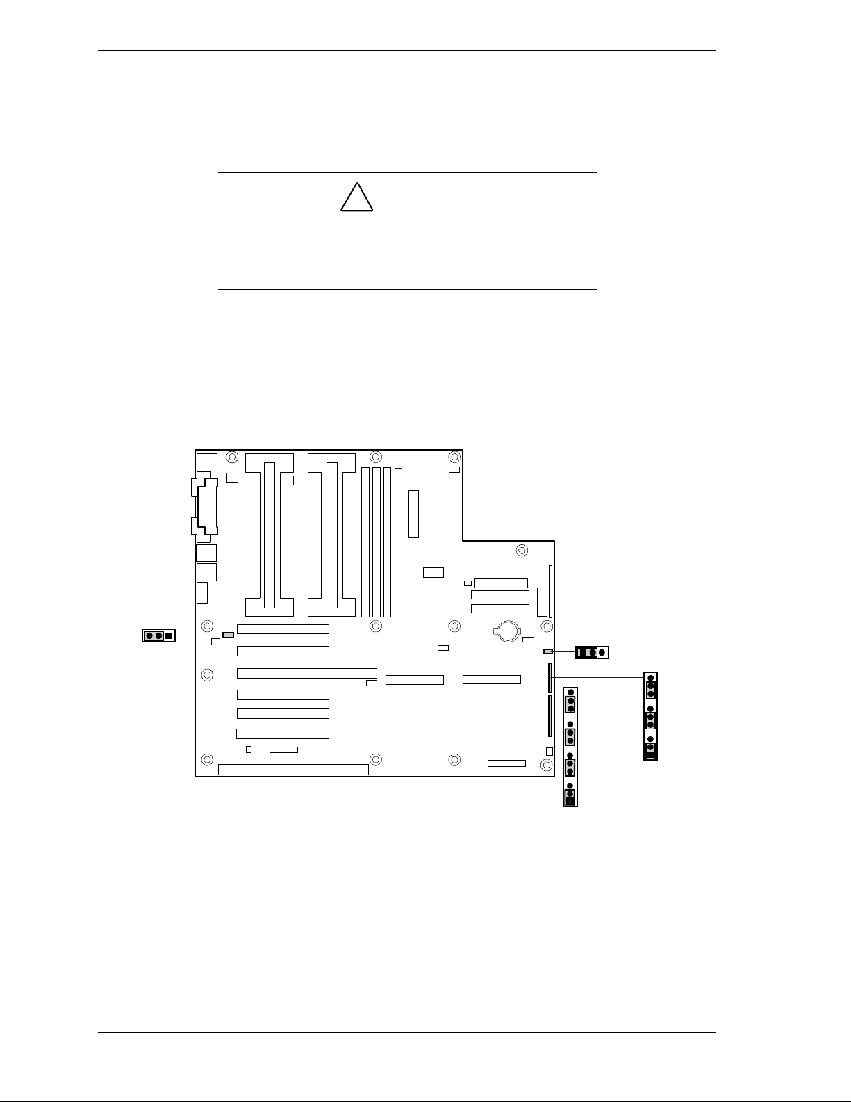
Configuring System Board Jumpers
Before You Begin
Only a qualified technical person should perform the procedures in this section.
!
CAUTION
Electrostatic discharge (ESD) can damage the system
board. Modify t he system boar d only at an ESD workstation.
Otherwise, wear an antistatic wrist strap attached to chassis
ground.
The system board jumpers e nab le you to set specific operating parameters for
your system. A jumper is a small plastic-encased conduct or (shorting plug) that
slips over two jumper pins.
The “System board Jumpers” illustrat ion show s the location of the system board
jumpers. The “System Board Jumper Configurat ions” table lists the system
board jumpers and their factory default settings.
WOL ENABLE
J5A2
BMC
1
WR EN
1
J4J2
J3J1
BIOS WR EN
J2J1
RCVRY BOOT
PSWD CLR
CMOS CLR
1
BMC FRC UP
INT DET
FRB
1
System Board Jumpers
3-24 Configuring Y our System
Page 77

System Board Jumper Summary
Jumper Block Function Pins (default in bol d) What it does at system reset
J5A2 Wake On LAN
ENABLE
J4J2 BMC Write
Enable
J3J1 FRB Timer
Enable
J3J1 Chassis
Intrusion
Detection
J3J1 BMC Forced
Update Mode
1-2, Disabled Disables Wake On LAN. If your power
supply does not provide 0.8 A of +5 V
Standby current, you must move the WOL
Enable jumper to this position.
2-3, Enabled Enables Wake On LAN.
1-2, Protect BMC boot block i s write protected.
2-3, Erase/Program BMC boot block is erasable and
programmable.
1-2, Enable FRB operation is enabl ed (system boots
fr om processor 1 if processor 0 does not
respond).
2-3, Disable FRB is disabled.
5-6, Enable Switch installed on chassis indicates wh en
cover has been removed.
6-7, Disable Chassis intrusion swit ch is bypassed.
9-10, Normal System boots normally.
10-11, Program System attempts to update BMC firmware.
J2J1 CMOS Clear
J2J1 Password Clear
J2J1 Recovery Boot
J2J1 BIOS Write
Enable
1-2, Protect
2-3, Erase Replaces the content s of NVRAM with the
5-6, Protect
6-7, Erase Clears the password.
9-10, Normal
10-11, Recovery
13-14, Protect
14-15, Erase/Program BIOS boot block is erasable and
Preserves the contents of NVRAM.
manufacturing default settings.
Maintains the current system password.
System attempts to boot using the BIOS
stored in flash m emory.
BIOS attempts a r ecovery boot, loading
BIOS code from a floppy diskette into the
flash device. This is typically used when the
BIOS code has been corrupted.
BIOS boot block is write-protected.
programmable.
Configuring Your System 3-25
Page 78

Moving System Board Jumpers
!
CAUTION
Before doing the procedur es i n this section, make sure that
your system is powered off and unplug the AC power cords
from the back of the chassis. Failure to disconnect power
before moving the jumper s can resul t in personal injury and
equipment damage.
Observe static pr ec autions. Use an antistatic wrist strap.
To configure the system board options:
1.
Power off the system and remove the left panel as described in Chapter 4 of
this guide.
2.
Check to ensure the system power cor d is removed from the back of the
system.
3.
Locate the position of the jumpers o n t he syst em board you are changing. To
change a jumper setting, use a pair of needle-nose pliers or your fingers to
remove the jumper from its current location. Position the jumper over the
two pins for the desired setting and press it onto the pins. Be careful not to
bend the pins. Re fer t he System Board Summary table for s yste m boar d
jump e r settings.
4.
Reinstall the left panel and power up the system.
3-26 Configuring Y our System
Page 79

Resetting the CMOS NVRAM
Use the clear CMOS memor y procedur es, which includes the reset CMOS
NVRAM process, under "Enable F2 Prompt by Changing a Jumper and Using
SSU" in C hapter 5.
Clearing and Changing the Passwords
To clear and change the passwords:
1. Power off the system and remove the left panel as described in chapter 4 of
this guide.
2. Mo ve the Password Clear jumper from pins 5-6 to pins 6-7. Refer to
“Configuring Syste m Board Jumpers” to see the location of this jumper.
3. Power on the system and wait for POST to complete. This automatically
clears the old password.
4. Power off the system.
5. Move t he Password Clear jumper back to pins 5-6.
6. Replace the panel and po wer on the system.
7. To specify a new passwo r d run t he BIOS S et up Utility as descr ibed ear lier
in th is chapter.
Recovering the BIOS
Qualified technical personnel should only perform this procedure.
Leave Recovery Boot jump er at factory-default setting.
A technically qualified person should only move t his j um per.
Boot Block Write Protect
The jumper at pins 13, 14, and 15 controls whether the BIOS boot block is
protected from being erased and reprogrammed.
Leave boot block jumper at factory- default setting:
Programming the boot bloc k inc or r ectly will pr event the
system from booti ng. A technically qualified person should
only do programming. T he pr oc edur e r equires a special
“Boot Block Updat e Utility.” Contact your dealer or sales
representative for more information.
!
CAUTION
!
CAUTION
Configuring Your System 3-27
Page 80

Fault Resilient Booting (FRB) Timer Enable Jumper
Fault resilient booting insur es the system will not stop from a boot problem.
Two s e ts of timers a re implement e d that will automatically reset the syst em if
the system shou ld halt for so me reason.
FRB 2 - 5 sec timer. If the primary processor does not come up in 5
seconds the system will automatically reset and switch to the seco ndary
processo r seco ndary (if installed otherwise it will tr y to boot again off of
the primary.)
FRB 3 - 7 minute timer. If the system does not make it up to the end of
POST in 7 minutes, the system will automatically reset and t r y again. It
is assumed that the processor failed regardless of what may have caused
the system to hang. The primary processor is taken off line and the
system will boot off the secondar y (if installed otherwise it will tr y to
boot again off of the primary.) Bad memory or a bad plug in card may
cause a FRB 3 failure.
All failures are logged to the system event log.
The system will remember all FRB errors and display them at the end of POST
until you select the Processor Retest option from the BIOS Setup utility.
!
CAUTION
For normal operation leave FRB Timer Enable jumper at
factory-defaul t set t ing.
To d is able the FRB Timer Ena ble:
1.
Power off the system and remove the left panel as described in Chapter 4 of
this guide.
2.
Move the FRB Timer Enable jumper from pins 1-2 to pins 2- 3. Refer to
“Configuring Syste m Board Jumpers” to see the location of this jumper.
3.
Replace the panel and power on the system.
4.
Power on the system and wait for POST to comp lete.
5.
Run the SSU to configure the system.
3-28 Configuring Y our System
Page 81

Chassis Intrusion Detection Jumper
The chassis contains a n a larm sw itc h t hat sends a notificat ion signa l to t he
server management so ftwar e if a cover is removed. The jumper at pins 5, 6, and
7 controls whether this alarm feature is enabled or disabled.
!
CAUTION
For normal operation leave Chassis Intrusion Detection
jumper at factory-default setting.
To disable the chassis intrusion switch:
1.
Power off the system and remove the left panel as described in Chapter 4 of
this guide.
2.
Move the chassis intrusion detection jumper from pins 5-6 to pins 6-7 to
disable the alarm switch.
3.
Reinsta ll the side cover for your safety, and connect the power cord to the
system.
4.
Power on the system on, and wait for POST to complete.
5.
Run the SSU to configure the system.
BMC Forced Update Mode
Leave BMC Forced Update Mode jumper at f actorydefault setting:
the system from booting. A technically qualified per son
should only do programmi ng. Contact your dealer or sales
representative for more information.
Setting this jumper incor r ectly will prevent
!
CAUTION
Configuring Your System 3-29
Page 82

3-30 Configuring Y our System
Page 83

4
Disassembly and Reassembly
General Information
Static Precaut i ons
Preparing Your System for Disassembly and
Reassem bly
Equipment Log
Opening the Front Door
Removing a Side Panel
Installing a Side Panel
Modifying the System Board
Option Boards
Hard Disk Drives
Removable Media Devices
Removing the Front Door Assembly
Removing the Top Cover
Removing the Chassis Ski rt
Removing a Chassis Foot
Removing the Front Panel Speaker/Switch
Assembly
Removing the Keylock Bracket
Page 84

Removing the Side Panel Intrusion and Interlock
Switch As semblies
Removing the Front Cover Intrusion Switc h
Assembly
Removing the Fans
Removing the Power Supply
Removing the System Board and Processor
Retention Module
Removing the SAF-TE Card
Removing the SCSI Backplane
Page 85
General Information
This chapter contains procedures for disassembling and reassembling your
server system unit. For reassembling your server unit, follow the disassemble
procedure in reverse order.
When disasse mb l ing and reassembl ing your server system unit, fo llow these
general rules.
!
The DC push-button on/off switch on the front panel does
not turn off the system A C power. Al so, +5v dc is present on
the system board whenever the AC power cords are
connected between the system and an AC outlet. Before
doing the procedures i n this manual, make sure that your
system is powered off and unpl ug the AC power cords from
the back of the chassis. Failure to disconnect power befor e
opening your system c an r esul t in personal injury and
equipment damage.
!
The server management logic on your system board
monitors and logs system v oltage changes. When powering
down your system you may experience a 1–5 second delay
from the time you press the push-butt on power on/off switch
on the front panel and your system poweri ng down. T his is
normal system operation and is required by the server
management logic.
WARNING
CAUTION
!
CAUTION
Operating your system with the side panels removed can
damage your system components. For proper cooling and
airflow, always replac e the side panels before powering on
your system.
Note:
ac power source is off or disconnected.
When disassembling disconnect all options.
When handling boards or chips, touch the system unit frame to release
Your system error log will be lost, if your system
static.
Do not disassemble parts other than those specified in the procedure.
All screws are Phillips-head, unless otherwise specified.
Disassembly and Reassembly 4-3
Page 86

Label all removed connectors. Not e where the connector goes and in
what po sition it was installed.
On completion of any reassembly, plug in the power cords and po wer on
the system unit.
Contact your sa les represe nt ative or dealer for a list of approved optional
peripheral devices.
Static Precautions
An electrostat ic discharge (ESD) can damage disk drives, opt ion boards, and
other components. You can provide some ESD protection by wearing an
antistatic wrist st r ap att ached to chassis ground when handling syste m
components.
Electronic devices can be easily damaged by static electricity. To prevent
damage, keep them in their protective packaging when they are not installed in
your system.
Preparing Your System for Disassembly and Reassembly
Depending on the upgrade, you will need one or more of the following tools:
Phillips screwdriver (#1 bit and #2 bit)
Flat-head screwdriver
Sma ll needle nose pliers
Pen or pencil
ESD workst ation or antistatic wrist strap (recommended)
Equipment Log
Use the equipment log form located at the end of this manual to recor d the
model and serial number of your system, all installed options, and any other
per tine nt information s pecific to yo ur s ystem. You w ill need this information
when configuring your system.
Opening the Front Door
To open the front door (see "Front View with Front Door Opened" in
Chapter 2. )
4-4 Disassembl y and Reassembly
Page 87
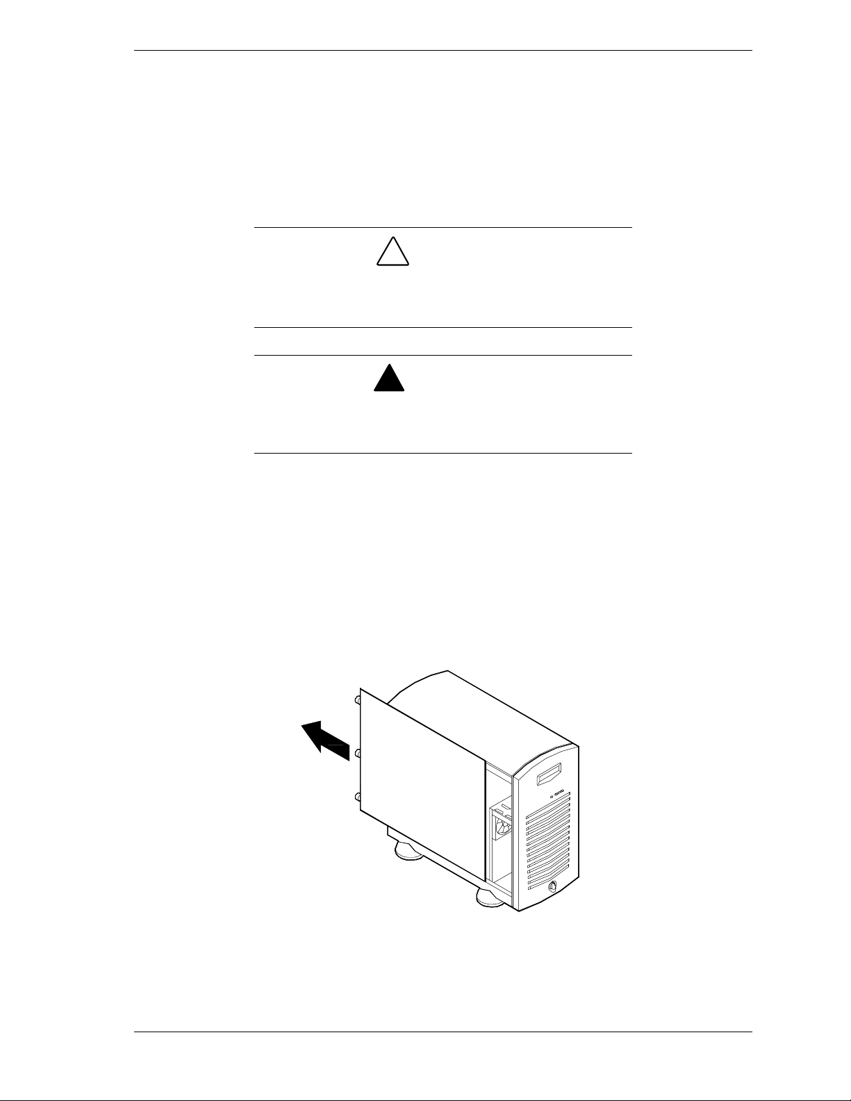
Removing a Side Panel
To ins ta ll options in your system, you mu s t re move t he side panel on t he left
side of your system (as viewed from the front). The side panel on the right side
of the system (as viewed fro m the front ) only has to be removed when adding
removable media devices or a second power supply. The right side panel
removes in the same manner as t he left side pane l.
!
CAUTION
For proper cooli ng and airflow, do not operate the system
with the side panels remov ed. Always replace the panels
before powering on t he system.
!
WARNING
If you are removing the si de panel aft er the system is set up,
you must first power off t he system and all external devices
and then
To remove a side panel:
Unplug
the system power cord
1.
Power off the system and ensure it is disconnected from the ac wall outlet.
2.
Loosen the three screws securing the side panel to the chassis.
3.
Slide the side panel toward the rear of the chassis. This unlocks the lock ing
fingers behind the side panel.
4.
Pull the side panel out and away from the chassis.
Removing a System Side Panel
Disassembly and Reassembly 4-5
Page 88

Installing a Side Panel
1. Before re plac ing the side panel, ma ke sure no tools or loos e parts have been
left inside the system chassis.
2. Make sure all option boards are firmly seated in their respective slots and
that all interior cables are proper ly connected.
3. Insert the metal tabs on the top and bottom of the side panel into their slots
on t he c hassis . S lid e the side p ane l forwa rd as far as it will go.
4. Tighten the three screws on the side panel securing it to the chassis.
If your system is already set up, plug the system
Note:
back in, reconnect the peripherals, and power on the
peripherals and system .
4-6 Disassembl y and Reassembly
Page 89
Modifying the System Board
The following sections provide procedures for upgrading and configuring the
system board in your system. Topics covered include:
Replacing the real-time clock battery
Replacing the processo r
Installing or removing DIMMs.
!
CAUTION
Electrostatic discharge (ESD) can damage add-in boards
and other components; place them on an antistatic surface.
Modify the system board only at an ESD workstation.
Otherwise, wear an antistatic wrist strap attached to chassis
ground.
Replacing the Real-time Clock Battery
You may need to replace the real-time clock battery because o f its life span. The
battery (Vendor Part #CR2032) is a commodity part available through many
vendors. Notice the plus (+) sign on the battery. This sign will assist you in
correctly positioning the batt er y on the system board.
!
CAUTION
Danger of explosion if battery is incorrectly repl ac ed.
Replace only with sam e or equivalent type recommended by
manufacturer. Dispose of lithium batteri es as requir ed by
local ordinanc e or as norm al waste if no local ordinance
exists. Do not expose the com ponent to excessive heat or
fire. Keep all batteries away from children
!
CAUTION
Observe static pr ec autions. Use an antistatic wrist strap.
Disassembly and Reassembly 4-7
Page 90
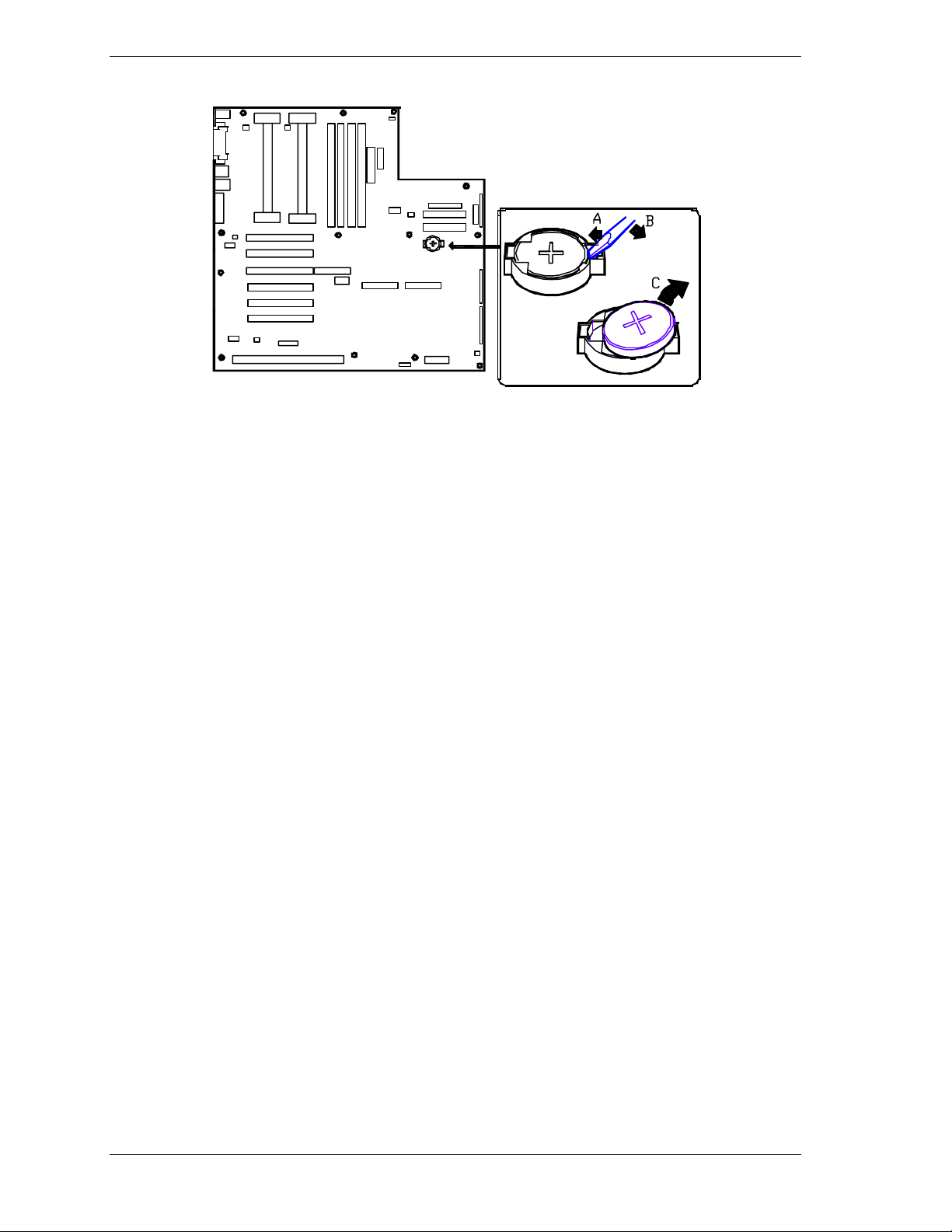
Replacing the Real-Ti me Clock Battery
1. Power off the system and remove the left side panel as described earlier in
this chapter.
2. Re move the plastic retainer on the lithium batter y socket.
3. Insert the tip of a small flat-bladed screwdriver, or equivalent, under the tab
in the plastic retainer (A in figure).
4. Gently push down on the screwdriver to lift the battery (B).
5. Remove the battery from its socket (C).
6. Dispose of the battery accord ing to local ordinance.
7. Remove the new lithium batt er y from its package, and, being careful t o
observe the cor r ect po larit y, insert it in the battery socket .
8. Reinst all the plastic retainer o n the lith iu m battery socket.
9. Replace the side panel, p lug in the system power cor d, and tur n on the
system.
10. Run the BIOS Setup to restore the configuration settings to the real-time
clock.
4-8 Disassembl y and Reassembly
Page 91
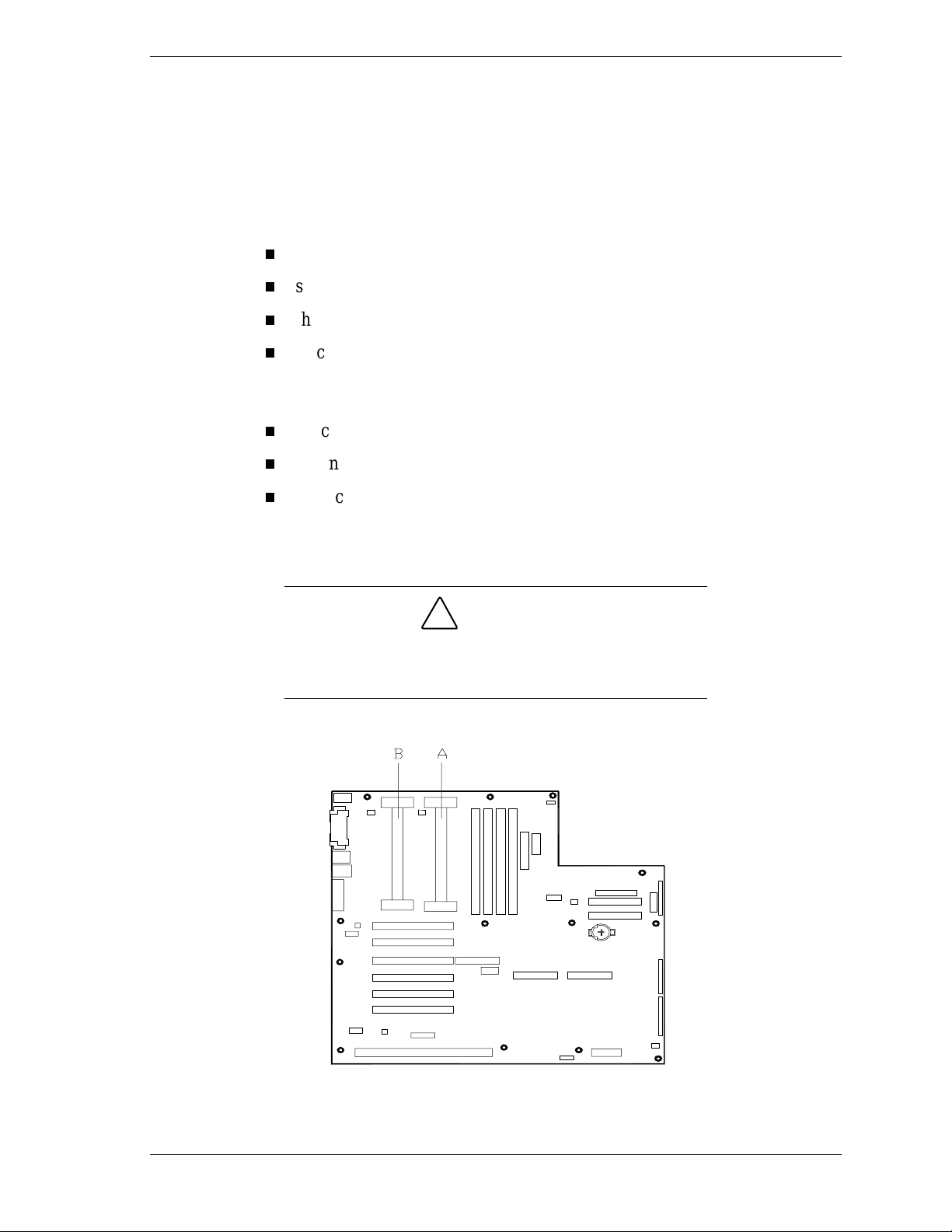
Replacing a Processor
This subsection provides the procedure for upgrading and configuring the
Processo r s in your system. The syst em board has sockets for two processors.
Each processo r is packaged either in a Single Edge Contact Cartridge (SECC) or
Single Edge Contact Cartridge Version 2 (SECC2).
The SECC packaged cartr idge includes:
processor core with an integrat ed 16 KB primary (L1) cache
secondary (L2) cache
t hermal pla te
back cover.
The SECC2 packaged cartr idge includes:
processor core with an integrat ed 16 KB primary (L1) cache
secondary (L2) cache.
back cover.
The primary processor co nnector is shown at (A) in the illustration below. The
secondary processor connector is shown at (B).
!
CAUTION
Electrostatic discharge (ESD) can damage components;
place them on an antistatic surface. Modify the system board
using an antistatic wri st str ap attached to chassis ground.
Replacing a Processor
Disassembly and Reassembly 4-9
Page 92
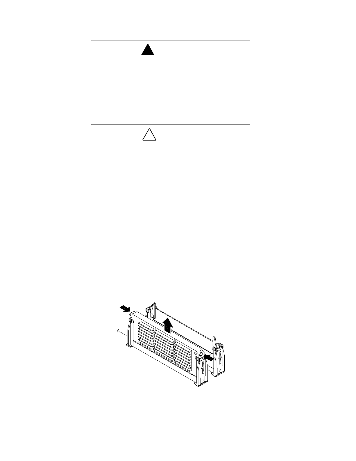
Replacing the SECC Version
If the system has been running, any processor and heat sink
already installed on the board will be hot. To avoid the
possibility of a burn, let the components cool for 10 minutes
before conti nuing with the procedures described here
1.
Power off the system and remove the left side panel as described earlier in
this chapter.
Observe static pr ec autions. Use an antistatic wrist strap.
Hold the processor only by its edges.
2.
If your system has one processor and you would like to add a second
processo r, co nt act your Serv ice Represe nt ative for assistance.
3.
If your system has one pro cessor and you are replacing it, leave the
termination board intact in the empty secondary processor connector.
Remove the processor you want to replace.
!
WARNING
!
CAUTION
4.
If your system has two processors and you are replacing one or both, remove
the appropriate o ne(s).
5.
Press the processor latches toward the center of the SEC cartridge to free
them from the retention module (see A in Figure "Re mo v ing a Processor").
6.
Lift the SEC cartridge upward, out of the retention module.
7.
Put the processor in a piece of conduct ive foam and store in an antistatic
package.
Removing a Pr ocessor
4-10 Disassembl y and Re assembly
Page 93
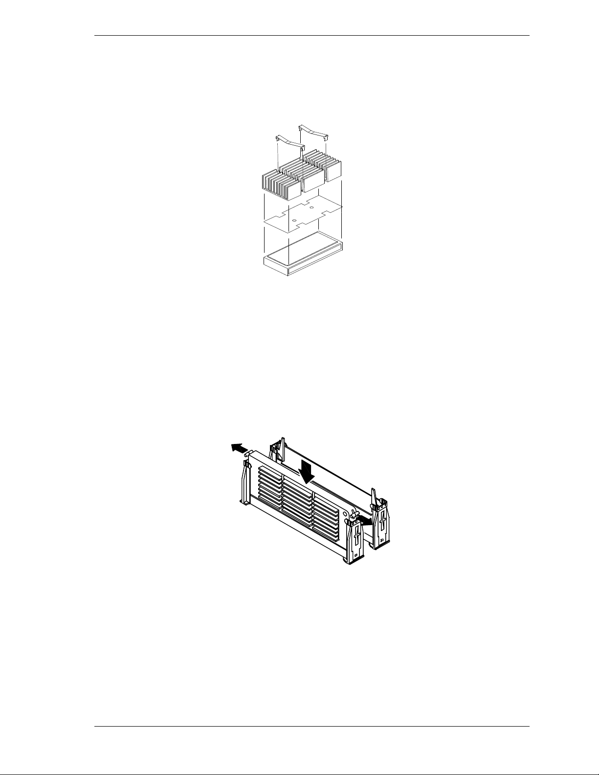
8. Place the ther mal pad on to p of the processo r so that the ho les in the ther mal
pad line up with the holes in the processor.
9. Position the heat sink on top of the processor.
10. Install the two clips that secur e t he heat s ink to t he processor.
Assembling the Processo r
11. Position the processor so that the heat sink faces to the left of the syste m
board. Slide the processor into the retention module. Ensure that the
alignment notch in the SEC cartridge fits over the plug in Slot 1. Push down
firmly, with even pressure on both sides of the top, until the SEC cartridge is
seated.
12. To lock in the processor, push the latches outward until they click into place
in the reten tion mo dule (see figure, below). T h e lat ches mu st be secure d for
proper electrical connection of the processor.
Locking in the Processor
13. After you have installed a new processor, you must run the BIOS Setup
Utility (F2) to configure its speed. Refer to Chapter 3, “Configuring Your
System.”
14. Replace the left side panel, plug in the system power cords, and power up
the system.
Disassembly and Reassembly 4-11
Page 94
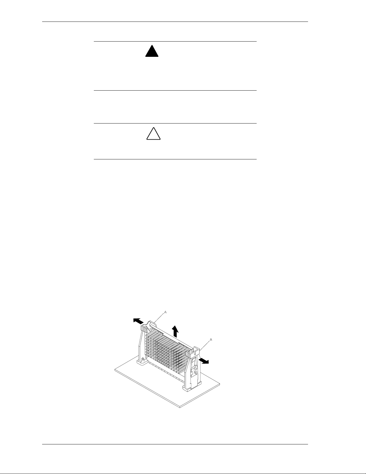
Replacing the SECC2 Version
If the system has been running, any processor and heat sink
already installed on the board will be hot. To avoid the
possibility of a burn, let the components cool for 10 minutes
before conti nuing with the procedures described here
1.
Power off the system and remove the left side panel as described earlier in
this chapter.
Observe static pr ec autions. Use an antistatic wrist strap.
Hold the processor only by its edges.
2.
If your system has one processor and you would like to add a second
processo r, t hen you must contact your Service Representat ive for assistance.
3.
If your system has one pro cessor and you are replacing it, leave the
termination board intact in the empty secondary processor connector.
Remove the processor you want to replace.
!
WARNING
!
CAUTION
4.
If your system has two processors and you are replacing one or both, remove
the appropriate o ne(s).
5.
Pull the processor latches, Item A in Figure "Removing a Processor " below,
out away from the edges of the SEC cartridge to free t hem fro m the
Universal Retention Module (UR M ).
6.
Lift the SEC cartridge upward, out of the URM and place it on a grounded,
static-free surface o r conductive foa m pad.
7.
Put the old processo r in a piece of conductive foam and store in an antistatic
package.
Removing a Pr ocessor
4-12 Disassembl y and Re assembly
Page 95

8. Remove the new processor from its antistatic package and place it o n a
grounded, static-free surface or conductive foam pad.
9. Position the processor back into the URM. Ensure that the alignment notch
in the SEC cartridge fits over the plug in Slot 1. Push down firmly, with
even pressure on both sides o f the to p, until the SEC cartridge is seated.
10. T o lock in the pro cessor, push the latches inward until they secure the SEC
cartridge into place in the URM, Item A in Figure "Remo ving a Processor"
above. The latches must be secured for proper electrical connection of the
processor.
11. After you have installed a new processor, you must run the BIOS Setup
Utility (F2) to configure its speed. Refer to Chapter 3, “Configuring Your
System.”
12. Replace the left side panel, plug in the system power cords, and power up
the system.
Disassembly and Reassembly 4-13
Page 96
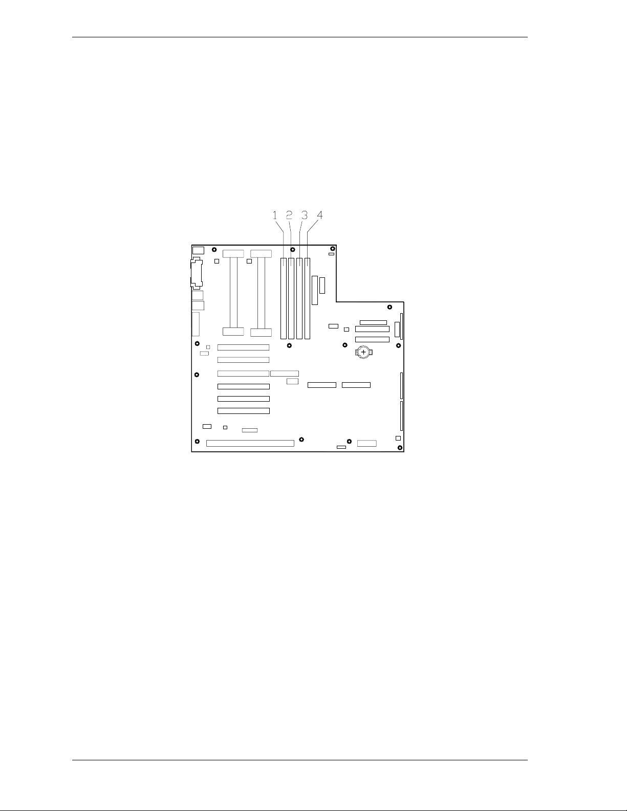
DIMMs
The system board cont ains four DI MM sockets labeled 1 through 4. Each socket
can hold a single 72-bit DIMM module with 32MB, 64MB, 128MB, or 256MB
of memory. When all four sockets are populated, the system board supports a
maximum of 1 GB of memory with 256MB DIMMs. A DIMM will always be
installed in the bottom soc ket. When you insta ll a dditio nal DIMMs, you mus t
start with the first empt y sock et above DIMMs alread y installed. Whe n you
remove DIMMs, you must start with the first DIMM so ck et closest to the top
edge of the system board.
DIMM Locations
4-14 Disassembl y and Re assembly
Page 97

Memory DIMM Configurations
This tabl e lists the distribution of DIMMs for specific memo ry co nfigu rations.
(MB)
32 32
64 32 32
64 64
96 32 32 32
96 64 32
128 32 32 32 32
128 64 32 32
128 64 64
128 128
160 64 64 32
160 64 32 32 32
160 64 64 32 32
192 64 64 32 32
192 64 64 64
192 128 32 32
192 128 64
224 64 64 64 32
224 128 32 32 32
224 128 64 32
256 64 64 64 64
256 128 64 32 32
256 128 64 64
256 128 128
256 256
288 128 64 64 32
288 128 128 32
320 128 64 64 64
320 128 128 32 32
320 128 128 64
352 128 128 64 32
384 128 128 64 64
384 128 128 128
384 256 128
416 128 128 128 32
448 128 128 128 64
512 128 128 128 128
512 256 256
640 256 256 128
768 256 256 128 128
768 256 256 256
896 256 256 256 128
1024 256 256 256 256
Slot 1 Slot 2 Slot 3 Slot 4
Capacity per DIMM slot (MB) Any DIMM slot orderSystem Capacity
Disassembly and Reassembly 4-15
Page 98
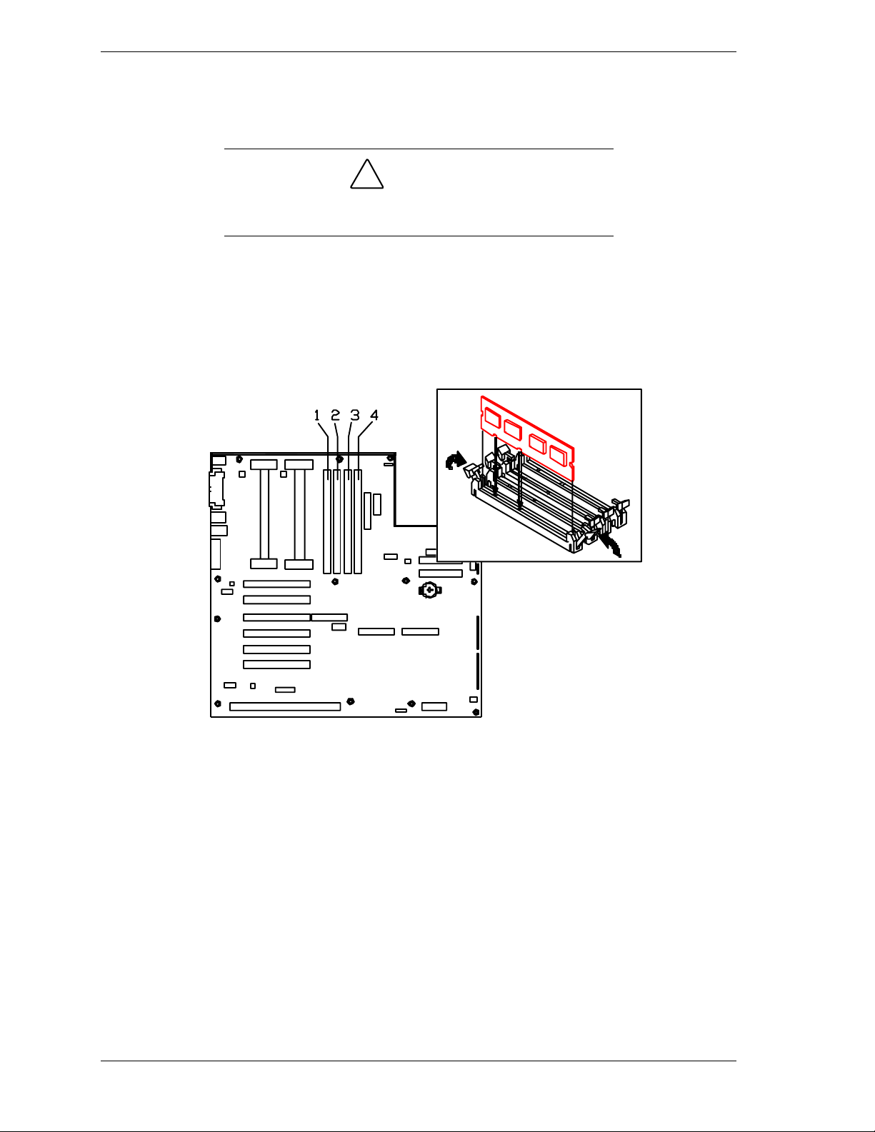
Installing DIMMs
1. Power off the system and remove the left side panel as described earlier in
this chapter.
2. Holding th e DIMM mod ule o nly by the edges , re mov e it from its antistatic
package.
3. Position the DIMM so that the two notches in the bottom edge of the DIMM
align with the keyed socket.
!
CAUTION
Observe static pr ec autions. Use an antistatic wrist strap.
Hold DIMMs only by their edges.
Inserting Memory DIMMs
4. Insert t he bottom edge of the DIMM into the socket, and press down firmly
on the DIMM until it seats correctly.
5. Gently push the plastic ejecto r levers on the so cket ends to the upright
position.
6. Repeat the steps to install each DIMM.
7. Replace the left side panel, plug in the system power cor d, and tu r n on the
system.
4-16 Disassembl y and Re assembly
Page 99

Removing DIMMs
Use extreme care when removing a DIMM. Too much
pressure can damage the socket slot. Apply only enough
pressure on the plasti c ejec tor levers to release the DIMM
1.
Power off the system and remove the left side panel as described earlier in
this chapter.
2.
Gently push the plastic ejector levers out and down to eject a DIMM from its
socket.
3.
Hold the DIMM only by its edges, being careful not to touch its components
or gold edge connectors. Carefully lift it awa y from the so cket , and stor e it
in an antistatic package.
4.
Repeat the above steps to remove t he remaining DIMMs.
5.
Replace the side panel, plug in the system power cord, and tu r n on the
system.
!
CAUTION
Disassembly and Reassembly 4-17
Page 100
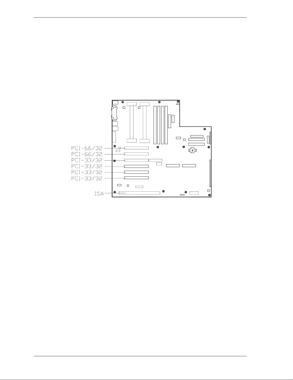
Option Boards
This section describes how to install and remove ISA and PCI option boards.
The system board has one ISA bus expansion slots and four PCI-33/32 bit and
two PCI-66/32 bit bus expansion slots.
The high-performance PCI loca l bus allows t he adopt ion of newer networ king
technology, such as 100 Mb/second Ethernet NICs, with a minimum of effort
and without concern for I/O bott lenecks. The PCI loca l bus offers up to 133
Mb/s ec o nd ba nd w id t h.
PCI and ISA Slot Locations
Installation Considerations
Newer adapters, designed for Plug-and-P lay systems, ar e aut omatically
configured by the system without any user intervent ion. Older ISA adapters
must be manually configured as detailed below. Once the ma nual configuration
is complete, the Plug-and-Play adapters are configured around the manually
configured adapters without causing any reso ur ce conflict s.
ISA adapters can be Plug-and-Play. ISA adapters that are not Plug-and-Play
must be manually configured following the instructions supplied with the board.
The configuration is defined to the system by creating the ISA configuration file
when running the SSU. If you are adding a non-Plug and Play ISA option board,
run the SSU before installing the board. For details on running the SSU, refer to
Appendix B.
4-18 Disassembl y and Re assembly
 Loading...