

Page 1

®
NDA-24347
ISSUE 1
STOCK # 152051
Configuration Guide
MAY, 2002
NEC America, Inc.
Page 2

LIABILITY DISCLAIMER
NEC Corporation reserves the right to change the specifications, functions,
or features, at any time, without notice.
NEC Corporation has prepar ed this document for use by its employe es
and NEC subsidiary. The information contained herein is the property of
NEC Corporation and shall not be reproduced without prior written
approval from NEC Corporation.
NEAX® and Dterm® are registered trademarks of NEC Corporation.
Copyright 2002
NEC Corporation
Printed in the U.S.A
Page 3

PAGE No.
ISSUE No.
1 2 3 4 5 6 7 8
i 1
ii 1
iii 1
iv 1
v 1
vi 1
1 1
2 1
3 1
4 1
5 1
6 1
7 1
8 1
9 1
10 1
11 1
12 1
13 1
14 1
15 1
16 1
17 1
18 1
19 1
20 1
21 1
22 1
23 1
24 1
25 1
26 1
27 1
28 1
29 1
30 1
31 1
32 1
ISSUE 1 ISSUE 2 ISSUE 3 ISSUE 4
DATE MAY, 2002 DATE DATE DATE
ISSUE 5 ISSUE 6 ISSUE 7 ISSUE 8
DATE DATE DATE DATE
PAGE No.
12345678
33 1
34 1
35 1
36 1
37 1
38 1
39 1
40 1
41 1
42 1
43 1
44 1
45 1
46 1
47 1
48 1
49 1
50 1
51 1
52 1
53 1
54 1
55 1
56 1
57 1
58 1
59 1
60 1
61 1
62 1
63 1
64 1
65 1
66 1
67 1
68 1
69 1
70 1
ISSUE No.
NEAX 2000 IPS
Configuration Guide
Revision Sheet 1/2
NDA-24347
Page 4

PAGE No.
71 1
72 1
73 1
74 1
75 1
76 1
77 1
78 1
79 1
80 1
81 1
82 1
83 1
84 1
85 1
86 1
ISSUE No.
12345678
PAGE No.
ISSUE No.
12345678
ISSUE 1 ISSUE 2 ISSUE 3 ISSUE 4
DATE MAY, 2002 DATE DATE DATE
ISSUE 5 ISSUE 6 ISSUE 7 ISSUE 8
DATE DATE DATE DATE
NEAX 2000 IPS
ConfigurationGuide
Revision Sheet 2/2
NDA-24347
Page 5

NDA-24347
ISSUE 1
MAY, 2002
NEAX 2000 IPS
Configuration Guide
TABLE OF CONTENTS
Page
List of Figures . . . . . . . . . . . . . . . . . . . . . . . . . . . . . . . . . . . . . . . . . . . . . . . . . . . . . . . . . . . iv
List of Tables . . . . . . . . . . . . . . . . . . . . . . . . . . . . . . . . . . . . . . . . . . . . . . . . . . . . . . . . . . . vi
Chapter 1 Introduction . . . . . . . . . . . . . . . . . . . . . . . . . . . . . . . . . . . . . . . . . . . . . . . . . . . 1
NEAX 2000 Internet Protocol Server (IPS) . . . . . . . . . . . . . . . . . . . . . . . . . . . . . . . . . . . . . . . . . 1
NEAX 2000 IPS Highlights. . . . . . . . . . . . . . . . . . . . . . . . . . . . . . . . . . . . . . . . . . . . . . . . . . . 3
Chapter 2 System Configuration . . . . . . . . . . . . . . . . . . . . . . . . . . . . . . . . . . . . . . . . . . . 7
Port Interface Modules (PIMs). . . . . . . . . . . . . . . . . . . . . . . . . . . . . . . . . . . . . . . . . . . . . . . . . . . 7
Floor-standing Installation . . . . . . . . . . . . . . . . . . . . . . . . . . . . . . . . . . . . . . . . . . . . . . . . . . . . . . 9
Wall-mounting Installation . . . . . . . . . . . . . . . . . . . . . . . . . . . . . . . . . . . . . . . . . . . . . . . . . . . . . . 10
19-inch Rack-mounting Installation . . . . . . . . . . . . . . . . . . . . . . . . . . . . . . . . . . . . . . . . . . . . . . . 11
System Outline. . . . . . . . . . . . . . . . . . . . . . . . . . . . . . . . . . . . . . . . . . . . . . . . . . . . . . . . . . . . . . . 12
Station-to-Station Connection . . . . . . . . . . . . . . . . . . . . . . . . . . . . . . . . . . . . . . . . . . . . . . . . 13
CCIS Connection. . . . . . . . . . . . . . . . . . . . . . . . . . . . . . . . . . . . . . . . . . . . . . . . . . . . . . . . . . 14
H.323 Connection . . . . . . . . . . . . . . . . . . . . . . . . . . . . . . . . . . . . . . . . . . . . . . . . . . . . . . . . . 1 5
System Conditions. . . . . . . . . . . . . . . . . . . . . . . . . . . . . . . . . . . . . . . . . . . . . . . . . . . . . . . . . . . . 15
Overall System. . . . . . . . . . . . . . . . . . . . . . . . . . . . . . . . . . . . . . . . . . . . . . . . . . . . . . . . . . . . 15
Peer-to-Peer Connection. . . . . . . . . . . . . . . . . . . . . . . . . . . . . . . . . . . . . . . . . . . . . . . . . . . . 16
CCIS Connection. . . . . . . . . . . . . . . . . . . . . . . . . . . . . . . . . . . . . . . . . . . . . . . . . . . . . . . . . . 16
H.323 Connection . . . . . . . . . . . . . . . . . . . . . . . . . . . . . . . . . . . . . . . . . . . . . . . . . . . . . . . . . 16
IP-PAD . . . . . . . . . . . . . . . . . . . . . . . . . . . . . . . . . . . . . . . . . . . . . . . . . . . . . . . . . . . . . . . . . . 16
Device Registration Server (DRS). . . . . . . . . . . . . . . . . . . . . . . . . . . . . . . . . . . . . . . . . . . . . 16
Legacy Interface (LT/AP) . . . . . . . . . . . . . . . . . . . . . . . . . . . . . . . . . . . . . . . . . . . . . . . . . . . . 16
Maintenance . . . . . . . . . . . . . . . . . . . . . . . . . . . . . . . . . . . . . . . . . . . . . . . . . . . . . . . . . . . . . 17
IP-PAD/VCT Card . . . . . . . . . . . . . . . . . . . . . . . . . . . . . . . . . . . . . . . . . . . . . . . . . . . . . . . . . 17
Mounting IP-PAD Card . . . . . . . . . . . . . . . . . . . . . . . . . . . . . . . . . . . . . . . . . . . . . . . . . . . . . . . . 17
Mounting VCT Card. . . . . . . . . . . . . . . . . . . . . . . . . . . . . . . . . . . . . . . . . . . . . . . . . . . . . . . . . . . 19
Mounting Conditions of IP-PAD/VCT Card . . . . . . . . . . . . . . . . . . . . . . . . . . . . . . . . . . . . . . . . . 20
BUS Cable Connection between IP-PAD and VCT Cards. . . . . . . . . . . . . . . . . . . . . . . . . . . . . . 21
LAN Cable Connection of IP-PAD Card. . . . . . . . . . . . . . . . . . . . . . . . . . . . . . . . . . . . . . . . . . . . 22
LAN Cable Connection of ETHER Card . . . . . . . . . . . . . . . . . . . . . . . . . . . . . . . . . . . . . . . . . . . 23
NEAX 2000 IPS Configuration Guide
NDA-24347, Issue 1
Page i
Page 6

TABLE OF CONTENTS (CONTINUED)
Page
Chapter 3 Module and Installation Hardware . . . . . . . . . . . . . . . . . . . . . . . . . . . . . . . . . 25
Modules . . . . . . . . . . . . . . . . . . . . . . . . . . . . . . . . . . . . . . . . . . . . . . . . . . . . . . . . . . . . . . . . . . . . 25
Port Interface Module (PIM). . . . . . . . . . . . . . . . . . . . . . . . . . . . . . . . . . . . . . . . . . . . . . . . . . 25
Battery Module (BATTM) . . . . . . . . . . . . . . . . . . . . . . . . . . . . . . . . . . . . . . . . . . . . . . . . . . . . 27
Installation Hardware. . . . . . . . . . . . . . . . . . . . . . . . . . . . . . . . . . . . . . . . . . . . . . . . . . . . . . . . . . 27
Base/Top Assembly . . . . . . . . . . . . . . . . . . . . . . . . . . . . . . . . . . . . . . . . . . . . . . . . . . . . . . . . 27
Hanger Assembly. . . . . . . . . . . . . . . . . . . . . . . . . . . . . . . . . . . . . . . . . . . . . . . . . . . . . . . . . . 27
19-inch Bracket . . . . . . . . . . . . . . . . . . . . . . . . . . . . . . . . . . . . . . . . . . . . . . . . . . . . . . . . . . . 27
Optional Bracket . . . . . . . . . . . . . . . . . . . . . . . . . . . . . . . . . . . . . . . . . . . . . . . . . . . . . . . . . . 27
Chapter 4 Circuit Cards . . . . . . . . . . . . . . . . . . . . . . . . . . . . . . . . . . . . . . . . . . . . . . . . . . 37
NEAX 2000 IPS Circuit Cards . . . . . . . . . . . . . . . . . . . . . . . . . . . . . . . . . . . . . . . . . . . . . . . . . . . 37
Card Location. . . . . . . . . . . . . . . . . . . . . . . . . . . . . . . . . . . . . . . . . . . . . . . . . . . . . . . . . . . . . . . . 37
Common Control Cards. . . . . . . . . . . . . . . . . . . . . . . . . . . . . . . . . . . . . . . . . . . . . . . . . . . . . . . . 41
Main Processor (MP). . . . . . . . . . . . . . . . . . . . . . . . . . . . . . . . . . . . . . . . . . . . . . . . . . . . . . . 42
Firmware Processor (FP). . . . . . . . . . . . . . . . . . . . . . . . . . . . . . . . . . . . . . . . . . . . . . . . . . . . 44
Line/Trunk (LT) Cards . . . . . . . . . . . . . . . . . . . . . . . . . . . . . . . . . . . . . . . . . . . . . . . . . . . . . . . . . 45
Application Processor (AP) Cards . . . . . . . . . . . . . . . . . . . . . . . . . . . . . . . . . . . . . . . . . . . . . . . . 49
Chapter 5 System Power Supply . . . . . . . . . . . . . . . . . . . . . . . . . . . . . . . . . . . . . . . . . . 53
AC/DC Power Supply. . . . . . . . . . . . . . . . . . . . . . . . . . . . . . . . . . . . . . . . . . . . . . . . . . . . . . . . . . 53
DC/DC Power Supply . . . . . . . . . . . . . . . . . . . . . . . . . . . . . . . . . . . . . . . . . . . . . . . . . . . . . . . . . 53
Battery Backup. . . . . . . . . . . . . . . . . . . . . . . . . . . . . . . . . . . . . . . . . . . . . . . . . . . . . . . . . . . . . . . 54
Short-term Option . . . . . . . . . . . . . . . . . . . . . . . . . . . . . . . . . . . . . . . . . . . . . . . . . . . . . . . . . 54
Long-term Option. . . . . . . . . . . . . . . . . . . . . . . . . . . . . . . . . . . . . . . . . . . . . . . . . . . . . . . . . . 54
Power Failure Transfer (PFT) . . . . . . . . . . . . . . . . . . . . . . . . . . . . . . . . . . . . . . . . . . . . . . . . . . . 54
PZ-8PFTB . . . . . . . . . . . . . . . . . . . . . . . . . . . . . . . . . . . . . . . . . . . . . . . . . . . . . . . . . . . . . . . 54
Chapter 6 Cabling . . . . . . . . . . . . . . . . . . . . . . . . . . . . . . . . . . . . . . . . . . . . . . . . . . . . . . 55
Internal Cabling . . . . . . . . . . . . . . . . . . . . . . . . . . . . . . . . . . . . . . . . . . . . . . . . . . . . . . . . . . . . . . 56
BUS Cable. . . . . . . . . . . . . . . . . . . . . . . . . . . . . . . . . . . . . . . . . . . . . . . . . . . . . . . . . . . . . . . 56
Power Control Cable . . . . . . . . . . . . . . . . . . . . . . . . . . . . . . . . . . . . . . . . . . . . . . . . . . . . . . . 57
DC Power Cable . . . . . . . . . . . . . . . . . . . . . . . . . . . . . . . . . . . . . . . . . . . . . . . . . . . . . . . . . . 57
AC Cord. . . . . . . . . . . . . . . . . . . . . . . . . . . . . . . . . . . . . . . . . . . . . . . . . . . . . . . . . . . . . . . . . 59
External Cabling. . . . . . . . . . . . . . . . . . . . . . . . . . . . . . . . . . . . . . . . . . . . . . . . . . . . . . . . . . . . . . 60
IP Connection . . . . . . . . . . . . . . . . . . . . . . . . . . . . . . . . . . . . . . . . . . . . . . . . . . . . . . . . . . . . 60
Attendant Console . . . . . . . . . . . . . . . . . . . . . . . . . . . . . . . . . . . . . . . . . . . . . . . . . . . . . . . . . 62
Maintenance Administration Terminal (MAT) (RS-232C). . . . . . . . . . . . . . . . . . . . . . . . . . . . 63
Built-in SMDR/MCI on MP . . . . . . . . . . . . . . . . . . . . . . . . . . . . . . . . . . . . . . . . . . . . . . . . . . . 65
SMDR (with AP00)/PMS/Hotel Printer/MCI/CCIS Centralized SMDR. . . . . . . . . . . . . . . . . . 66
External Alarm Display. . . . . . . . . . . . . . . . . . . . . . . . . . . . . . . . . . . . . . . . . . . . . . . . . . . . . . 67
Digital Trunk Interface (DTI)/Primary Rate Interface (PRI)/CCIS Trunk Interface (CCT). . . . 68
Data Port Controller (DPC) . . . . . . . . . . . . . . . . . . . . . . . . . . . . . . . . . . . . . . . . . . . . . . . . . . 69
NEAX 2000 IPS Configuration Guide
Page ii NDA-24347, Issue 1
Page 7

TABLE OF CONTENTS (CONTINUED)
Page
DPC and X.21/V.35 Converter . . . . . . . . . . . . . . . . . . . . . . . . . . . . . . . . . . . . . . . . . . . . . . . . 70
Chapter 7 Dterm IP . . . . . . . . . . . . . . . . . . . . . . . . . . . . . . . . . . . . . . . . . . . . . . . . . . . . . 71
Dterm IP Setup . . . . . . . . . . . . . . . . . . . . . . . . . . . . . . . . . . . . . . . . . . . . . . . . . . . . . . . . . . . . . . 71
Dterm IP Login/Logout. . . . . . . . . . . . . . . . . . . . . . . . . . . . . . . . . . . . . . . . . . . . . . . . . . . . . . . . . 76
Dterm IP Login. . . . . . . . . . . . . . . . . . . . . . . . . . . . . . . . . . . . . . . . . . . . . . . . . . . . . . . . . . . . 76
Dterm IP Logout. . . . . . . . . . . . . . . . . . . . . . . . . . . . . . . . . . . . . . . . . . . . . . . . . . . . . . . . . . . 77
Chapter 8 System Capacity . . . . . . . . . . . . . . . . . . . . . . . . . . . . . . . . . . . . . . . . . . . . . . 79
Main Processor (MP) System . . . . . . . . . . . . . . . . . . . . . . . . . . . . . . . . . . . . . . . . . . . . . . . . . . . 79
Floor-standing Installation Equipment . . . . . . . . . . . . . . . . . . . . . . . . . . . . . . . . . . . . . . . . . . . . . 82
LT/AP Card Slots. . . . . . . . . . . . . . . . . . . . . . . . . . . . . . . . . . . . . . . . . . . . . . . . . . . . . . . . . . . . . 83
Line Conditions . . . . . . . . . . . . . . . . . . . . . . . . . . . . . . . . . . . . . . . . . . . . . . . . . . . . . . . . . . . . . . 84
Zone Transceiver Line Conditions. . . . . . . . . . . . . . . . . . . . . . . . . . . . . . . . . . . . . . . . . . . . . . . . 85
Traffic Capacity . . . . . . . . . . . . . . . . . . . . . . . . . . . . . . . . . . . . . . . . . . . . . . . . . . . . . . . . . . . . . . 86
System-based Device Registration Server (DRS). . . . . . . . . . . . . . . . . . . . . . . . . . . . . . . . . . . . 86
NEAX 2000 IPS Configuration Guide
NDA-24347, Issue 1 Page iii
Page 8

LIST OF FIGURES
Figure Title Page
Figure 1-1 NEAX 2000 Internet Protocol Server (IPS) . . . . . . . . . . . . . . . . . . . . . . . . . . . . . . . . . 1
Figure 1-2 Simplified View of NEAX 2000 IPS System Connectivity . . . . . . . . . . . . . . . . . . . . . . . 2
Figure 1-3 Hybrid System of IP and Time Division Switching . . . . . . . . . . . . . . . . . . . . . . . . . . . . 3
Figure 1-4 NEAX 2000 IPS MP and IP-PAD Configuration . . . . . . . . . . . . . . . . . . . . . . . . . . . . . . 4
Figure 2-1 System Configuration with Dterm IP (512-Port Configuration) . . . . . . . . . . . . . . . . . . . 8
Figure 2-2 Floor-standing Installation . . . . . . . . . . . . . . . . . . . . . . . . . . . . . . . . . . . . . . . . . . . . . . 9
Figure 2-3 Wall-mounting Installation . . . . . . . . . . . . . . . . . . . . . . . . . . . . . . . . . . . . . . . . . . . . . . 10
Figure 2-4 19-inch Rack-mounting Installation . . . . . . . . . . . . . . . . . . . . . . . . . . . . . . . . . . . . . . . 11
Figure 2-5 System Outline of NEAX 2000 IPS . . . . . . . . . . . . . . . . . . . . . . . . . . . . . . . . . . . . . . . 12
Figure 2-6 System Outline of Station-to-Station Connection . . . . . . . . . . . . . . . . . . . . . . . . . . . . . 13
Figure 2-7 System Outline of CCIS Connection . . . . . . . . . . . . . . . . . . . . . . . . . . . . . . . . . . . . . . 14
Figure 2-8 System Outline of H.323 Connection . . . . . . . . . . . . . . . . . . . . . . . . . . . . . . . . . . . . . . 15
Figure 2-9 Mounting IP-PAD Card . . . . . . . . . . . . . . . . . . . . . . . . . . . . . . . . . . . . . . . . . . . . . . . . . 18
Figure 2-10 Mounting VCT Card . . . . . . . . . . . . . . . . . . . . . . . . . . . . . . . . . . . . . . . . . . . . . . . . . . . 19
Figure 2-11 IP-PAD BUS Cable Connection . . . . . . . . . . . . . . . . . . . . . . . . . . . . . . . . . . . . . . . . . . 21
Figure 2-12 IP-PAD - Switching HUB Cable Connection . . . . . . . . . . . . . . . . . . . . . . . . . . . . . . . . 22
Figure 2-13 ETHER - Router/Switching HUB Cable Connection . . . . . . . . . . . . . . . . . . . . . . . . . . 23
Figure 3-1 Unit Configuration . . . . . . . . . . . . . . . . . . . . . . . . . . . . . . . . . . . . . . . . . . . . . . . . . . . . 25
Figure 3-2 PIMMD Face Layout . . . . . . . . . . . . . . . . . . . . . . . . . . . . . . . . . . . . . . . . . . . . . . . . . . 26
Figure 3-3 Floor-standing Installation . . . . . . . . . . . . . . . . . . . . . . . . . . . . . . . . . . . . . . . . . . . . . . 29
Figure 3-4 Wall-mounting Installation . . . . . . . . . . . . . . . . . . . . . . . . . . . . . . . . . . . . . . . . . . . . . . 30
Figure 3-5 19-inch Rack-mounting Installation (Bracket A) . . . . . . . . . . . . . . . . . . . . . . . . . . . . . . 31
Figure 3-6 19-inch Rack-mounting Installation (Bracket B) . . . . . . . . . . . . . . . . . . . . . . . . . . . . . . 32
Figure 3-7 Mounting Bracket . . . . . . . . . . . . . . . . . . . . . . . . . . . . . . . . . . . . . . . . . . . . . . . . . . . . . 33
Figure 3-8 I/F Bracket . . . . . . . . . . . . . . . . . . . . . . . . . . . . . . . . . . . . . . . . . . . . . . . . . . . . . . . . . . 34
Figure 3-9 Base Tray Assembly . . . . . . . . . . . . . . . . . . . . . . . . . . . . . . . . . . . . . . . . . . . . . . . . . . 35
Figure 4-1 PIM Face Layout . . . . . . . . . . . . . . . . . . . . . . . . . . . . . . . . . . . . . . . . . . . . . . . . . . . . . 37
Figure 4-2 Port Allocation of Time Division Switch . . . . . . . . . . . . . . . . . . . . . . . . . . . . . . . . . . . . 43
Figure 5-1 PZ-8PFTB Installation . . . . . . . . . . . . . . . . . . . . . . . . . . . . . . . . . . . . . . . . . . . . . . . . . 54
Figure 6-1 BUS Cable Connection . . . . . . . . . . . . . . . . . . . . . . . . . . . . . . . . . . . . . . . . . . . . . . . . 56
Figure 6-2 Power Cable Connection (Internal Battery Option) . . . . . . . . . . . . . . . . . . . . . . . . . . . 57
Figure 6-3 Power Cable Connection (External Battery Option) . . . . . . . . . . . . . . . . . . . . . . . . . . . 58
Figure 6-4 AC Cord Connection . . . . . . . . . . . . . . . . . . . . . . . . . . . . . . . . . . . . . . . . . . . . . . . . . . 59
Figure 6-5 IP BUS Cable Connection (IP PAD) . . . . . . . . . . . . . . . . . . . . . . . . . . . . . . . . . . . . . . . 60
Figure 6-6 IP BUS Cable Connection (IPT) . . . . . . . . . . . . . . . . . . . . . . . . . . . . . . . . . . . . . . . . . . 61
Figure 6-7 Attendant Console Cable Connection . . . . . . . . . . . . . . . . . . . . . . . . . . . . . . . . . . . . . 62
Figure 6-8 MAT Cable Connection (Direct) . . . . . . . . . . . . . . . . . . . . . . . . . . . . . . . . . . . . . . . . . . 63
Figure 6-9 MAT Cable Connection (Remote Connection via Internal Modem) . . . . . . . . . . . . . . . 64
Figure 6-10 MAT Cable Connection (Remote Connection via External Modem) . . . . . . . . . . . . . . 64
Figure 6-11 Cable Connection for Built-in SMDR/MCI on MP . . . . . . . . . . . . . . . . . . . . . . . . . . . . . 65
Figure 6-12 AP00 Cable Connection . . . . . . . . . . . . . . . . . . . . . . . . . . . . . . . . . . . . . . . . . . . . . . . . 66
Figure 6-13 External Alarm Display Connection . . . . . . . . . . . . . . . . . . . . . . . . . . . . . . . . . . . . . . . 67
Figure 6-14 DTI Cable Connection (Twisted-pair Cable) . . . . . . . . . . . . . . . . . . . . . . . . . . . . . . . . 68
NEAX 2000 IPS Configuration Guide
Page iv NDA-24347, Issue 1
Page 9

LIST OF FIGURES (CONTINUED)
Figure Title Page
Figure 6-15 DPC Cable Connection . . . . . . . . . . . . . . . . . . . . . . . . . . . . . . . . . . . . . . . . . . . . . . . . 69
Figure 6-16 DPC and X.21/V.35 Converter . . . . . . . . . . . . . . . . . . . . . . . . . . . . . . . . . . . . . . . . . . . 70
Figure 7-1 Dterm IP Display (ID Registration without Password) . . . . . . . . . . . . . . . . . . . . . . . . . 76
Figure 7-2 Dterm IP Display (ID Registration with Password) . . . . . . . . . . . . . . . . . . . . . . . . . . . . 76
NEAX 2000 IPS Configuration Guide
NDA-24347, Issue 1 Page v
Page 10

LIST OF TABLES
Table Title Page
Table 2-1 IP-PAD/VCT Card Mounting Conditions . . . . . . . . . . . . . . . . . . . . . . . . . . . . . . . . . . . . 20
Table 3-1 Modules. . . . . . . . . . . . . . . . . . . . . . . . . . . . . . . . . . . . . . . . . . . . . . . . . . . . . . . . . . . . . 27
Table 3-2 Installation Hardware . . . . . . . . . . . . . . . . . . . . . . . . . . . . . . . . . . . . . . . . . . . . . . . . . . 28
Table 4-1 Location of Cards . . . . . . . . . . . . . . . . . . . . . . . . . . . . . . . . . . . . . . . . . . . . . . . . . . . . . 38
Table 4-2 Common Control Cards and System Software. . . . . . . . . . . . . . . . . . . . . . . . . . . . . . . 41
Table 4-3 Line/Trunk (LT) Cards. . . . . . . . . . . . . . . . . . . . . . . . . . . . . . . . . . . . . . . . . . . . . . . . . . 45
Table 4-4 Application Processor (AP) Cards. . . . . . . . . . . . . . . . . . . . . . . . . . . . . . . . . . . . . . . . . 49
Table 5-1 AC/DC Power Card. . . . . . . . . . . . . . . . . . . . . . . . . . . . . . . . . . . . . . . . . . . . . . . . . . . . 53
Table 5-2 DC/DC (-48 V) Power Card. . . . . . . . . . . . . . . . . . . . . . . . . . . . . . . . . . . . . . . . . . . . . . 53
Table 5-3 PZ-8PFTB. . . . . . . . . . . . . . . . . . . . . . . . . . . . . . . . . . . . . . . . . . . . . . . . . . . . . . . . . . . 54
Table 6-1 BUS Cable . . . . . . . . . . . . . . . . . . . . . . . . . . . . . . . . . . . . . . . . . . . . . . . . . . . . . . . . . . 56
Table 6-2 Power Control Cable. . . . . . . . . . . . . . . . . . . . . . . . . . . . . . . . . . . . . . . . . . . . . . . . . . . 57
Table 6-3 Power Cable (Internal Battery Option) . . . . . . . . . . . . . . . . . . . . . . . . . . . . . . . . . . . . . 58
Table 6-4 Power Cable (External Battery Option). . . . . . . . . . . . . . . . . . . . . . . . . . . . . . . . . . . . . 58
Table 6-5 AC Cord . . . . . . . . . . . . . . . . . . . . . . . . . . . . . . . . . . . . . . . . . . . . . . . . . . . . . . . . . . . . 59
Table 6-6 IP BUS Cable (IP PAD). . . . . . . . . . . . . . . . . . . . . . . . . . . . . . . . . . . . . . . . . . . . . . . . . 60
Table 6-7 IP BUS Cable (IPT). . . . . . . . . . . . . . . . . . . . . . . . . . . . . . . . . . . . . . . . . . . . . . . . . . . . 61
Table 6-8 MAT Cable (Direct) . . . . . . . . . . . . . . . . . . . . . . . . . . . . . . . . . . . . . . . . . . . . . . . . . . . . 63
Table 6-9 MAT Cable (Remote Connection via External Modem) . . . . . . . . . . . . . . . . . . . . . . . . 64
Table 6-10 Cable for Built-in SMDR/MCI on MP. . . . . . . . . . . . . . . . . . . . . . . . . . . . . . . . . . . . . . . 65
Table 6-11 Cable for AP00 . . . . . . . . . . . . . . . . . . . . . . . . . . . . . . . . . . . . . . . . . . . . . . . . . . . . . . . 66
Table 6-12 External Alarm Display Panel . . . . . . . . . . . . . . . . . . . . . . . . . . . . . . . . . . . . . . . . . . . . 67
Table 6-13 DPC Cable . . . . . . . . . . . . . . . . . . . . . . . . . . . . . . . . . . . . . . . . . . . . . . . . . . . . . . . . . . 69
Table 6-14 DPC and X.21/V.35 Converter . . . . . . . . . . . . . . . . . . . . . . . . . . . . . . . . . . . . . . . . . . . 70
Table 7-1 User Menu Items. . . . . . . . . . . . . . . . . . . . . . . . . . . . . . . . . . . . . . . . . . . . . . . . . . . . . . 72
Table 7-2 Administrator Menu Items. . . . . . . . . . . . . . . . . . . . . . . . . . . . . . . . . . . . . . . . . . . . . . . 74
Table 8-1 Main Processor (MP) System . . . . . . . . . . . . . . . . . . . . . . . . . . . . . . . . . . . . . . . . . . . . 79
Table 8-2 Required Common Equipment for Floor-standing Installation . . . . . . . . . . . . . . . . . . . 82
Table 8-3 Number of Slots for LT/AP Cards of each PIM . . . . . . . . . . . . . . . . . . . . . . . . . . . . . . . 83
Table 8-4 Line Conditions . . . . . . . . . . . . . . . . . . . . . . . . . . . . . . . . . . . . . . . . . . . . . . . . . . . . . . . 84
Table 8-5 Zone Transceiver Line Conditions . . . . . . . . . . . . . . . . . . . . . . . . . . . . . . . . . . . . . . . . 85
Table 8-6 Traffic Capacity. . . . . . . . . . . . . . . . . . . . . . . . . . . . . . . . . . . . . . . . . . . . . . . . . . . . . . . 86
Table 8-7 System-based Device Registration Server (DRS) . . . . . . . . . . . . . . . . . . . . . . . . . . . . 86
NEAX 2000 IPS Configuration Guide
Page vi NDA-24347, Issue 1
Page 11

Chapter 1 Introduction
NEAX 2000 Internet Protocol Server (IPS)
NEAX 2000 Internet Protocol Server (IPS) is a full-featured IP-based
communications system providing a rich feature set of existing NEAX 2000 IVS
with pure Voice over IP (VoIP) communications (Peer-to-Peer connections), across
corporate Local and Wide Area Networks (LAN and WAN).
Dterm IP telephones are designed to provide a converged infrastructure at the desktop,
with a 100 BASE-T Ethernet connection to the LAN and built-in hub for a PC
connection to the telephone itself. The system can provide Peer-to-Peer connections
between Dterm IP telephones with voice compression, offering existing Dterm Series
E telephone features. In a WAN, the system can provide Peer-to-Peer connections
over IP networks with voice compression through CCIS (CCIS over IP).
The NEAX 2000 IPS can provide Legacy station/trunk interfaces to support the
existing Time Division Multiplexing (TDM) based infrastructure, such as analog
telephones, analog networks, and digital networks (T1/E1 and ISDN). The Legacy
station/trunk interface cards (LT and AP cards) can be accommodated in the Port
Interface Module (PIM), in the same manner as the NEAX 2000 IVS
configuration, the NEAX 2000 IPS supports 512 LT ports which can be 448 Dterm IP
telephones and 64 Legacy LT ports, and 256 ports for Legacy AP cards.
Communications between Legacy stations/trunks and Dterm IP telephones/IP
networks are made via IP PAD, that converts packet-based voice data to TDM-based
voice data, and vice versa. The new Main Processor (MP) card controls both
Peer-to-Peer connections and TDM-based connections. The new MP card
incorporates a built-in Device Registration Server (DRS) and single interface point of
IP connections to IP telephone, MATWorX, and OAI/ACD servers.
2
. At maximum
2
,
NEAX 2000 IPS Configuration Guide
NDA-24347, Issue 1
Figure 1-1 NEAX 2000 Internet Protocol Server (IPS)
Page 1
Page 12
NEAX 2000 Internet Protocol Server (IPS) Chapter 1 Introduction
NEAX 2000 IPS
MATWorX
(via RS-232C)
Dterm IP
DRS
SLT/Dterm
LC/DLC
IP-PAD
Switching HUB (100 Mbps)
Switching
HUB
TDSW
MP
COT
TIE
IPT (H.323
Handler)
Router
Router
PSTN
H.323 GK
Internet
/Intranet
MATWorX
(via LAN)
NEAX 2000 IPS
MATWorX
(via IPT: CCIS)
Router
OAI
Server
DHCP
Server
Dterm IP
Client PC
Client PC
Dterm IP
Figure 1-2 Simplified View of NEAX 2000 IPS System Connectivity
NEAX 2000 IPS Configuration Guide
Page 2 NDA-24347, Issue 1
Page 13
Chapter 1 Introduction NEAX 2000 Internet Protocol Server (IPS)
NEAX 2000 IPS Highlights
NEAX 2000 IPS highlights are as follows:
• Hybrid System of IP (Peer-to-Peer connection) and TDM Switching
The NEAX 2000 IPS supports both pure IP switching (Peer-to-Peer connections)
and Time Division switching. The pure IP switching is provided for
communications between Dterm IP telephones and for CCIS network with
another NEAX 2000 IPS/2400 IPX (CCIS over IP). On the other hand, the TDM
switching is provided for communications between Legacy stations/trunks.
Connections between Dterm IP/CCIS over IP and Legacy stations/trunks are
made via IP PADs, which converts packet-based voice data to TDM-based voice
data, and vice versa.
Linked with CCIS over IP
Note 1
Peer-to-Peer
Connection
(CCIS)
Router
IP Network
NEAX 2000 IPS
Speech Path
with TSW
NEAX 2000 IPS/
NEAX 2400 IPX
Dterm IP
Dterm IP
LAN
Peer-to-Peer
Connection
(Dterm IP)
TSW
IP PAD
Note 2
LT/TRK
AP
Built-in DRS
Note 3
Time Division
Switching
IP Switching
Call Control
MP
IP/TSW Conversion
Figure 1-3 Hybrid System of IP and Time Division Switching
Note 1: CCIS over IP using Peer-to-Peer connections is available with the NEAX
2000 IPS and NEAX 2400 IPX only.
Note 2: IP PAD: IP Packet Assembly Disassembly
Note 3: DRS: Device Registration Server
NEAX 2000 IPS Configuration Guide
NDA-24347, Issue 1
Page 3
Page 14
NEAX 2000 Internet Protocol Server (IPS) Chapter 1 Introduction
RS
RS
• One-board Main Processor (MP) with Integrated Functionality
NEAX 2000 IPS Main Processor (MP) is the heart of pure IP connections and
TDM-based connections. The MP employs a high-speed CPU, which is
equivalent with Pentium. With this processing power and System On Chip (SOC)
technology, the MP integrates Device Registration Server (DRS), AP01 (OAI)
functions, which are provided by an additional card in the previous NEAX 2000
IVS series. Also, by means of LSI technology, the MP card size is minimized and
an Ethernet Interface Card is mounted on the MP without using an additional slot
space in the PIM. This interface card is linked with LAN for call control
processing of Dterm IP and inter-work with MATWorX and OAI server.
PN-CP24-A
Power
Supply
Circuit
(Pentiumequivalent)
AP01 Function and TCP/IP
protocol are integrated into MP
osc
OSC
New
Engine
Chip
Alarm and
DK Circuit
Source
IP PAD
MOH
MOH
Source
Driver
Driver
Connector
Transforme
PN-32IPLA
+
PN-16VCTA
Ethernet
NIC
r
Connector
PZ-M606-A
Figure 1-4 NEAX 2000 IPS MP and IP-PAD Configuration
NEAX 2000 IPS Configuration Guide
Page 4 NDA-24347, Issue 1
Page 15

Chapter 1 Introduction NEAX 2000 Internet Protocol Server (IPS)
• Built-in Device Registration Server (DRS) on MP
The NEAX 2000 IPS incorporates the DRS on the MP, which provides
Log-in/Log-out management of the Dterm IP including Registration,
Authentication. Also, the built-in DRS can communicate with the DHCP server to
provide easy administration of IP address.
• Enhanced Built-in Firmware Processor (FP) on MP
NEAX 2000 IVS2 requires FP card in PIM 0 when the system configured with
three or more PIMs. In the case of the NEAX 2000 IPS, an FP in PIM 0 is not
required since the Built-in FP function in the MP has been improved, providing
more call processing capability. (FP is used in PIM 2, 4 and 6.)
• Migration Path for NEAX 2000 IVS2
For the customers who are using NEAX 2000 IVS2, the migration path is
supplied. By replacing the existing MP card to a new one, the NEAX 2000 IVS
can be upgraded to IP/TSW Hybrid System including new and enhanced service
features introduced with the NEAX 2000 IPS. If a user wants to implement
Peer-to-Peer connection services, it is available by adding the IP PAD to the
existing system with the new MP.
• Reduced Hardware with IP based Architecture
The Dterm IP telephones accommodated in LAN do not require a DLC card
because they can be interfaced directly with LAN and have Peer-to-Peer
connection. When a Dterm IP is connected with a station/trunk, which is
accommodated in the TSW, the speech path between LAN and TSW is made via
IP PAD under the call processing control of MP. The Dterm IP can be expanded
by adding the terminal itself and IP PAD if traffic volume is increased. With this
system architecture, the hardware (DLC, PIM, and Power Supply) is reduced.
This makes moves, adds, and changes easier.
• Office Data Backup Enhancement
The office data of NEAX 2000 IPS is stored in Flash ROM. Therefore the backup
period is extended compared with previous NEAX 2000 systems that used RAM
with battery.
• Various Installation Methods
2
• Unified Circuit Card Size
NEAX 2000 IPS Configuration Guide
NDA-24347, Issue 1
To meet the specific needs of the customer’s environment, NEAX 2000 IPS
provides the following installation methods:
• Floor-standing Installation
• Wall-mounting Installation
• IEC standard 19-inch Rack-mounting Installation
All the circuit cards for NEAX 2000 IPS are designed in one size (PN-type), and
installed in the PIM. This ensures that slot space is used efficiently within the
PIM.
Page 5
Page 16

NEAX 2000 Internet Protocol Server (IPS) Chapter 1 Introduction
• High Density Line/Trunk (LT) Cards
Major Line/Trunk cards used in NEAX 2000 IPS are provided with eight circuits
per card. This allows the physical system size to be compact.
• Universal Slot
One PIM provides 12 card slots for Line/Trunk (LT). These card slots can also be
used for Application Processor (AP) cards without complicated limitation. As this
makes easy quotation and installation, more number of AP cards can be mounted
in one PIM.
• DC/DC Power Supply for -48 V
The PIM houses an optional DC/DC Power Supply for the cards that require -48 V
power (such as the CSI card, used as the interface for a wireless system’s Zone
Transceiver). Since this power supply is mounted in the space under the AC/DC
power, no additional Power Module/card slots are required.
• Extended Application Processor (AP) Port Capacity
The NEAX 2000 IPS provides maximum 256 AP ports and it is independent of
the 512 ports for the Line/Trunk (LT). Therefore, more number of AP cards can
be used in the system such as T1/E1 digital link.
NEAX 2000 IPS Configuration Guide
Page 6 NDA-24347, Issue 1
Page 17

Chapter 2 System Configuration
Port Interface Modules (PIMs)
NEAX 2000 IPS consists of a number of Port Interface Modules (PIMs) depending on
the system configuration. There are two types of PIMs:
• Physical PIM
• Virtual PIM
The Physical PIM is a hardware PIM and is used to accommodate an MP, FPs, IP
PADs, Legacy LT and AP cards, and power supply units. One Physical PIM provides
up to 64 LT ports.
The Virtual PIM is a software PIM and is used to assign Dterm IP telephones by
system programming (The Physical PIM can be used to assign Dterm IP telephones,
but is not essential.). One Virtual PIM provides up to 64 Dterm IP telephones. The
system consists of up to eight PIMs, by the combination of Physical PIMs and Virtual
PIMs, thus providing a total of 512 ports for Dterm IP telephones and Legacy LT
cards. Total number of ports for Dterm IP telephones and Legacy LT cards must be
less than 512, so the number of Physical PIMs decreases when that of Virtual PIMs (=
number of Dterm IP telephones) increases.
Example: When 256 Legacy LT ports are required (= four Physical PIMs), the
maximum number of Dterm IP telephones is 256.
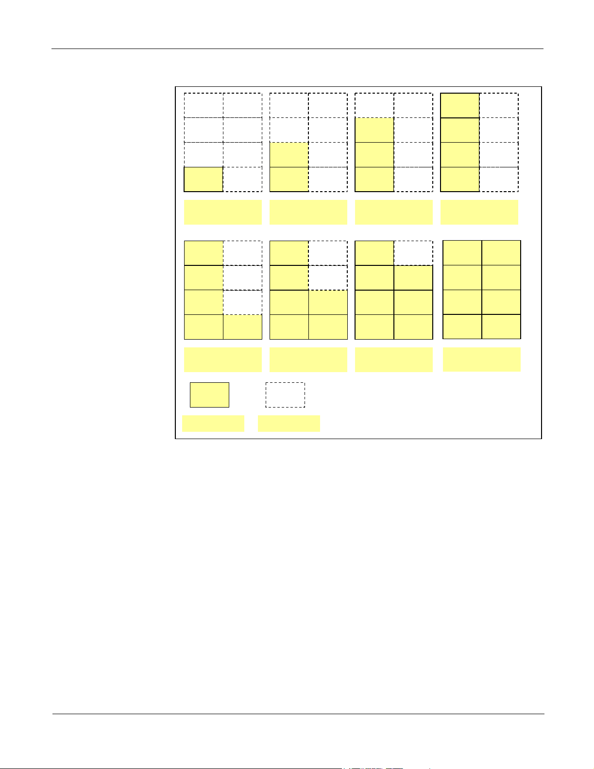
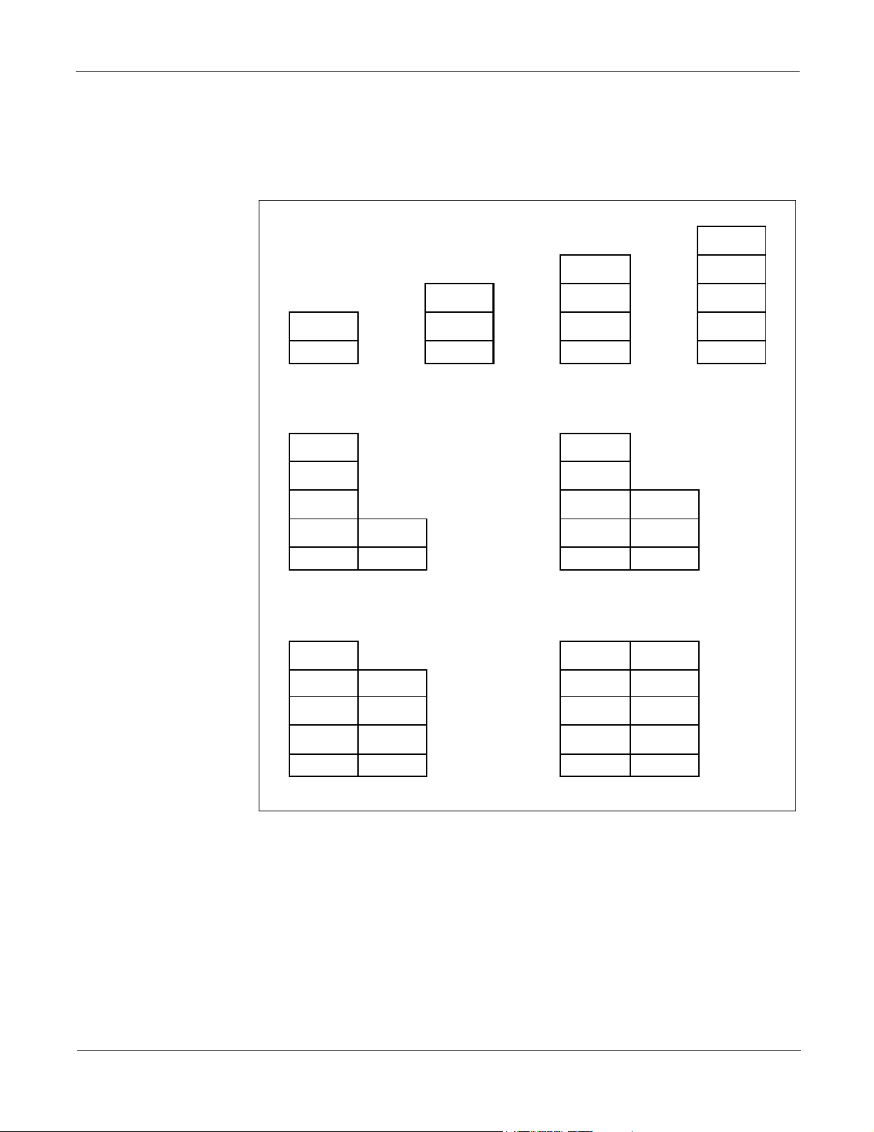
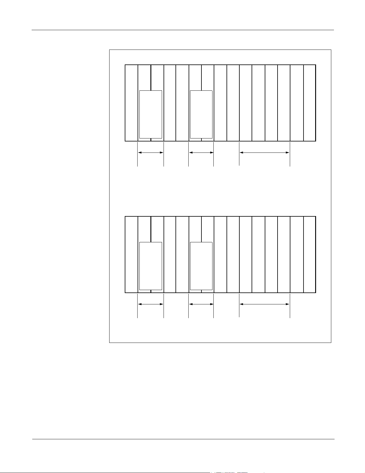
Figure 2-1 shows examples of 512-port configuration by the combination of Legacy
LT ports and Dterm IP telephones.
NEAX 2000 IPS Configuration Guide
NDA-24347, Issue 1
Page 7
Page 18
Port Interface Modules (PIMs) Chapter 2 System Configuration
PIM 3
PIM 7
PIM 3
PIM 7
PIM 3
PIM 7
PIM 3
PIM 7
PIM 2
PIM 1
PIM 0
64 LT ports +
448 Dterm IPs
PIM 3
PIM 2
PIM 1
PIM 0
320 LT ports +
192 Dterm IPs
PIM
PIM 6
PIM 5
PIM 4 PIM 0 PIM 4 PIM 0 PIM 4 PIM 0 PIM 4
PIM 7
PIM 6
PIM 5
PIM 4
PIM 2
PIM 1
128 LT ports +
384 Dterm IPs
PIM 3
PIM 2
PIM 1
PIM 0 PIM 4
384 LT ports +
128 Dterm IPs
PIM
PIM 6
PIM 5
PIM 7
PIM 6
PIM 5
PIM 2
PIM 1
192 LT ports +
320 Dterm IPs
PIM 3
PIM 2
PIM 1 PIM 5
PIM 0 PIM 4
448 LT ports +
64 Dterm IPs
PIM 6
PIM 5
PIM 7
PIM 6
PIM 2
PIM 1
256 LT ports +
256 Dterm IPs
PIM 3
PIM 2
PIM 1 PIM 5
PIM 0 PIM 4
512 LT ports +
0 Dterm IPs
PIM 6
PIM 5
PIM 7
PIM 6
Physical PIM
Virtual PIM
Figure 2-1 System Configuration with Dterm IP (512-Port Configuration)
NEAX 2000 IPS Configuration Guide
Page 8 NDA-24347, Issue 1
Page 19
Chapter 2 System Configuration Floor-standing Installation
(
)
(
)
Floor-standing Installation
In Floor-standing Installation, the NEAX 2000 IPS is comprised of up to eight Port
Interface Modules (PIMs).
PIM 3
PIM 2 PIM 2
PIM 1
PIM 0
BASE
(64 ports) (128 ports) (192 ports) (256 ports)
PIM 3
PIM 2
PIM 1
PIM 0
BASE
(320 ports)
PIM 3
PIM 2
PIM 4
BASE
PIM 6
PIM 0
BASE BASE BASE
PIM 1
PIM 0
PIM 3
PIM 2
PIM 1
PIM 0
BASE
(384 ports)
PIM 3
PIM 2
PIM 1
PIM 0
PIM 5
PIM 4
BASE
PIM 7
PIM 6
PIM 1
PIM 0
BASE
448 ports
PIM 5
PIM 4
BASE
PIM 1
PIM 0
BASE
PIM 5
PIM 4
BASE
512 ports
Figure 2-2 Floor-standing Installation
NEAX 2000 IPS Configuration Guide
NDA-24347, Issue 1
Page 9
Page 20
Wall-mounting Installation Chapter 2 System Configuration
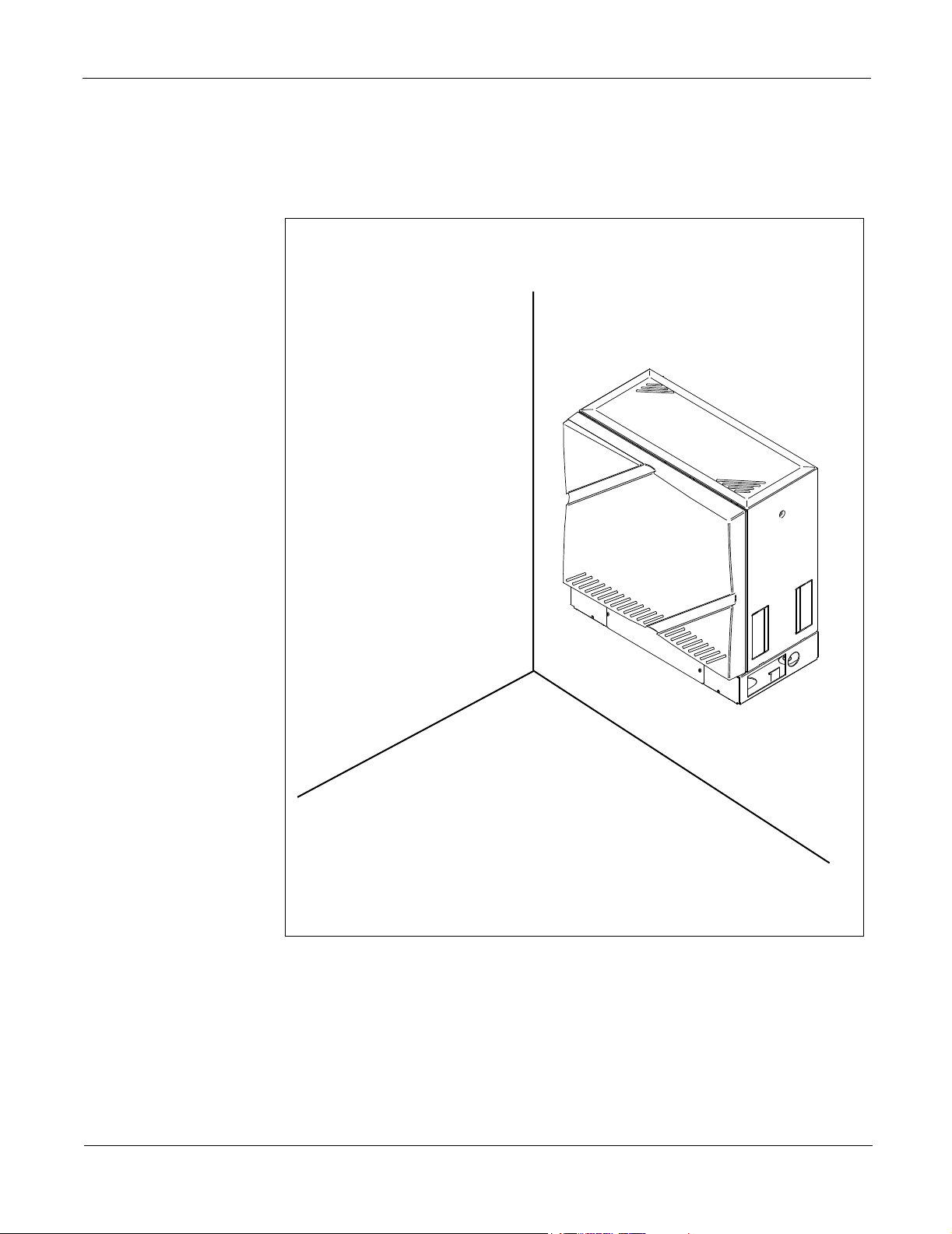
Wall-mounting Installation
The NEAX 2000 IPS can be wall-mounted in a single or multiple PIM configuration.
A maximum of eight PIMs can be mounted in this way.
Figure 2-3 Wall-mounting Installation
NEAX 2000 IPS Configuration Guide
Page 10 NDA-24347, Issue 1
Page 21
Chapter 2 System Configuration 19-inch Rack-mounting Installation
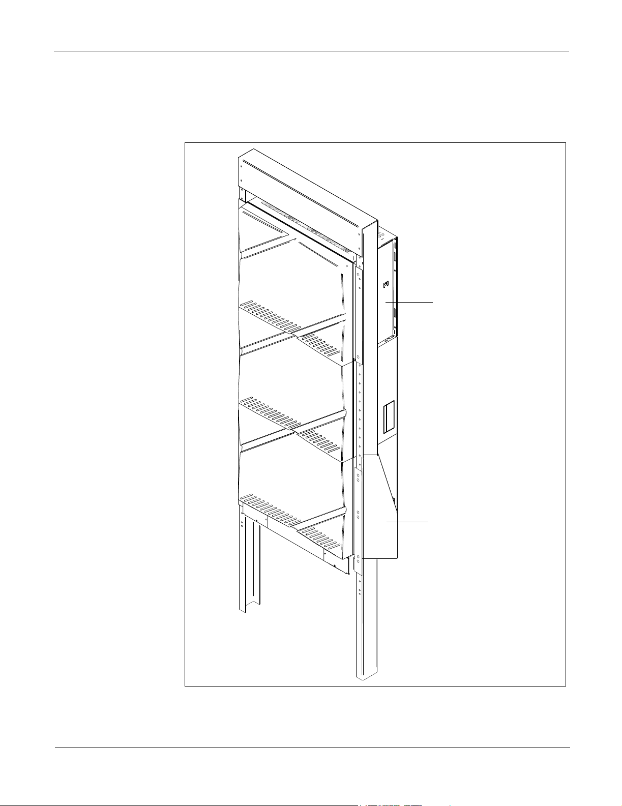
19-inch Rack-mounting Installation
The NEAX 2000 IPS can be mounted in the IEC-standard 19-inch rack. A maximum
of four PIMs can be mounted in this way.
19-inch Bracket (A)
NEAX 2000 IPS Configuration Guide
NDA-24347, Issue 1
19-inch Bracket (B)
Figure 2-4 19-inch Rack-mounting Installation
Page 11
Page 22
System Outline Chapter 2 System Configuration
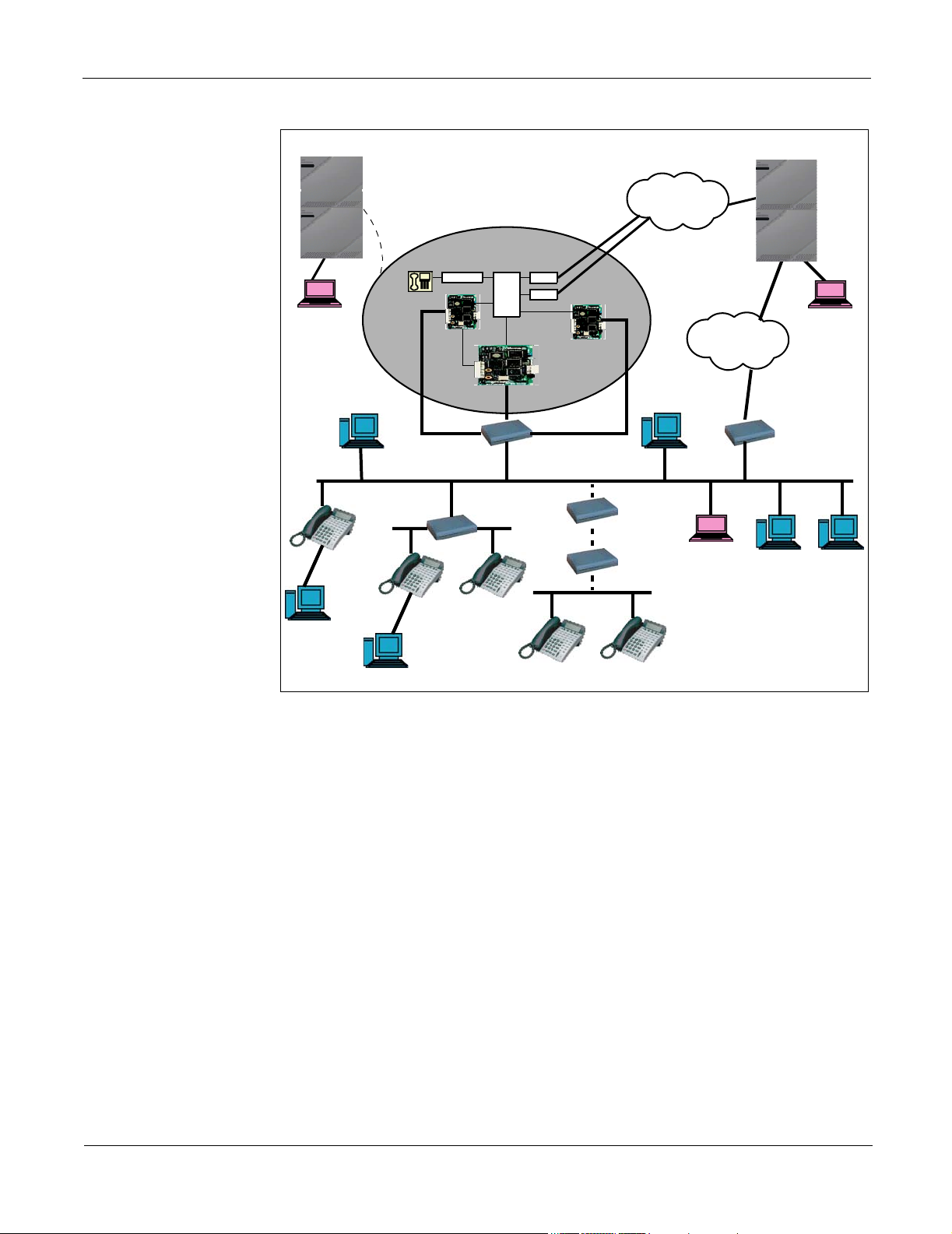
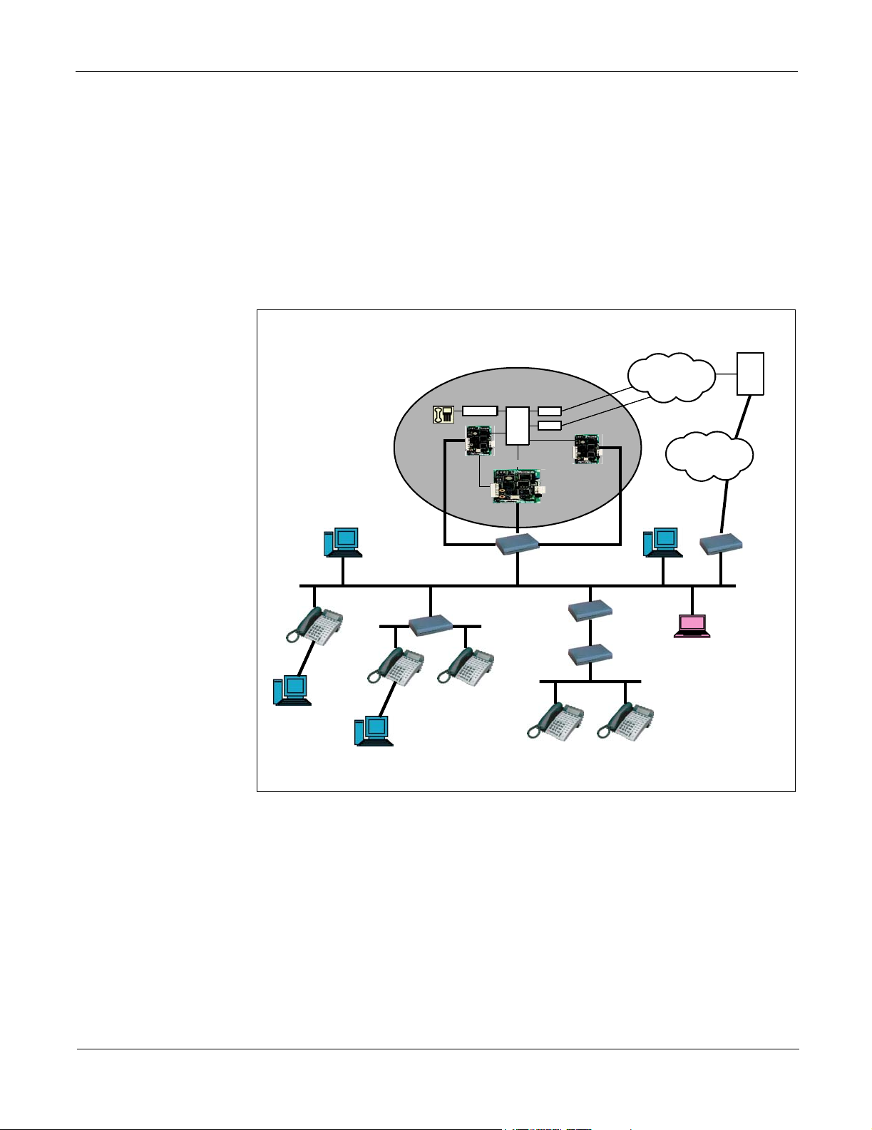
System Outline
The NEAX 2000 IPS is an IP communication system that integrates the voice
terminals to the IP network through Peer-to-Peer connection.
The system is a hybrid system to accommodate both IP multi-line terminals (Dterm
IP) and the terminals used in Legacy PBXs (Legacy terminal).
Line/Trunk cards and Application Processor cards can be mounted in the system to
provide the features that are provided by Legacy Time Division Switch (TDSW)
PBXs.
DRS-Network Based (as Proxy)
Dterm IP
Client PC
Client PC
Switching HUB (100 Mbps)
Switching HUB
SLT/Dterm
IP-PAD
Dterm IP
LC/DLC
NEAX 2000 IPS
TDSW
1board MP
C.O.
TIE
IPT (H.323
Handler)
Dterm IP
Router
Router
PSTN/
GSTN
H.323 GK
MAT (via LAN)
INTERNET/
INTRANET
Router
PBX
LAN
Figure 2-5 System Outline of NEAX 2000 IPS
NEAX 2000 IPS Configuration Guide
Page 12 NDA-24347, Issue 1
Page 23
Chapter 2 System Configuration System Outline
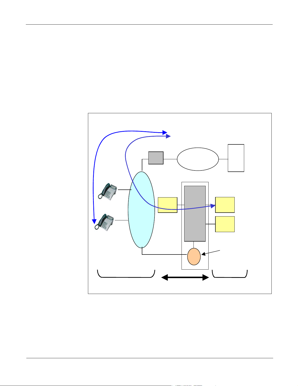
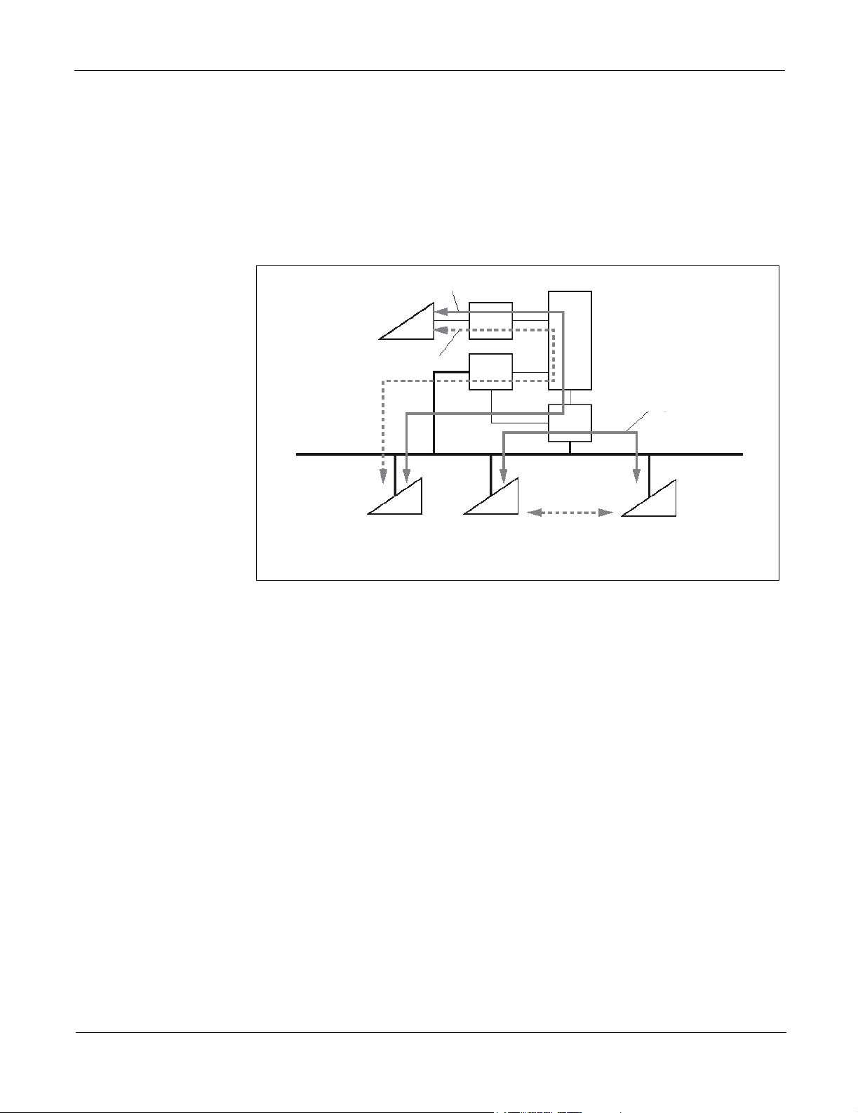
Station-to-Station Connection
For Dterm IP-to-Dterm IP connection (Peer-to-Peer connection), the voice data is
transmitted and received directly between Dterm IP telephones on the LAN.
For Dterm IP-to-Legacy terminal connection, the IP-PAD card and VCT card are
required to transmit and receive the voice data. These cards are used to control and
convert the voice data.
The control signals are managed by the MP card in both types of connections.
Control Signal
Dterm IP
TDSW
(PROTIMS over IP)
Control Signal
MP
LAN
Dterm IP
Legacy Terminal
Voice Data
Dterm IP
LC/DLC
IP-PAD
Voice Data
(Peer-to-Peer Connection)
Figure 2-6 System Outline of Station-to-Station Connection
NEAX 2000 IPS Configuration Guide
NDA-24347, Issue 1
Page 13
Page 24
System Outline Chapter 2 System Configuration
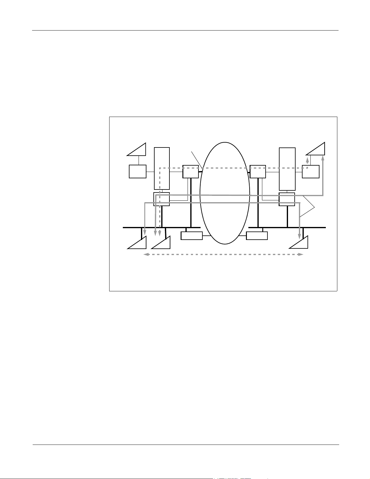
CCIS Connection For Dterm IP-to-Dterm IP connection via CCIS (Peer-to-Peer connection), the voice
data is transmitted and received directly between Dterm IP telephones via Intranet
(CCIS via IP).
For Dterm IP-to-Legacy terminal connection via CCIS, the IP-PAD card and VCT
card are required to transmit and receive the voice data. These cards are used to
control and convert the voice data.
The MP card manages the control signals in both types of connections.
Legacy Terminal
LC/DLC
LAN
Dterm IP
Voice Data
TDSW
IP-PAD
Dterm IP
MP
IP-PAD
ROUTER ROUTER
INTERNET/
INTRANAT
(CCIS via IP)
Voice Data
(Peer-to-Peer Connection)
Figure 2-7 System Outline of CCIS Connection
TDSW
MP
Legacy Terminal
LC/DLC
Control
Signal
LAN
Dterm IP
NEAX 2000 IPS Configuration Guide
Page 14 NDA-24347, Issue 1
Page 25
Chapter 2 System Configuration System Conditions
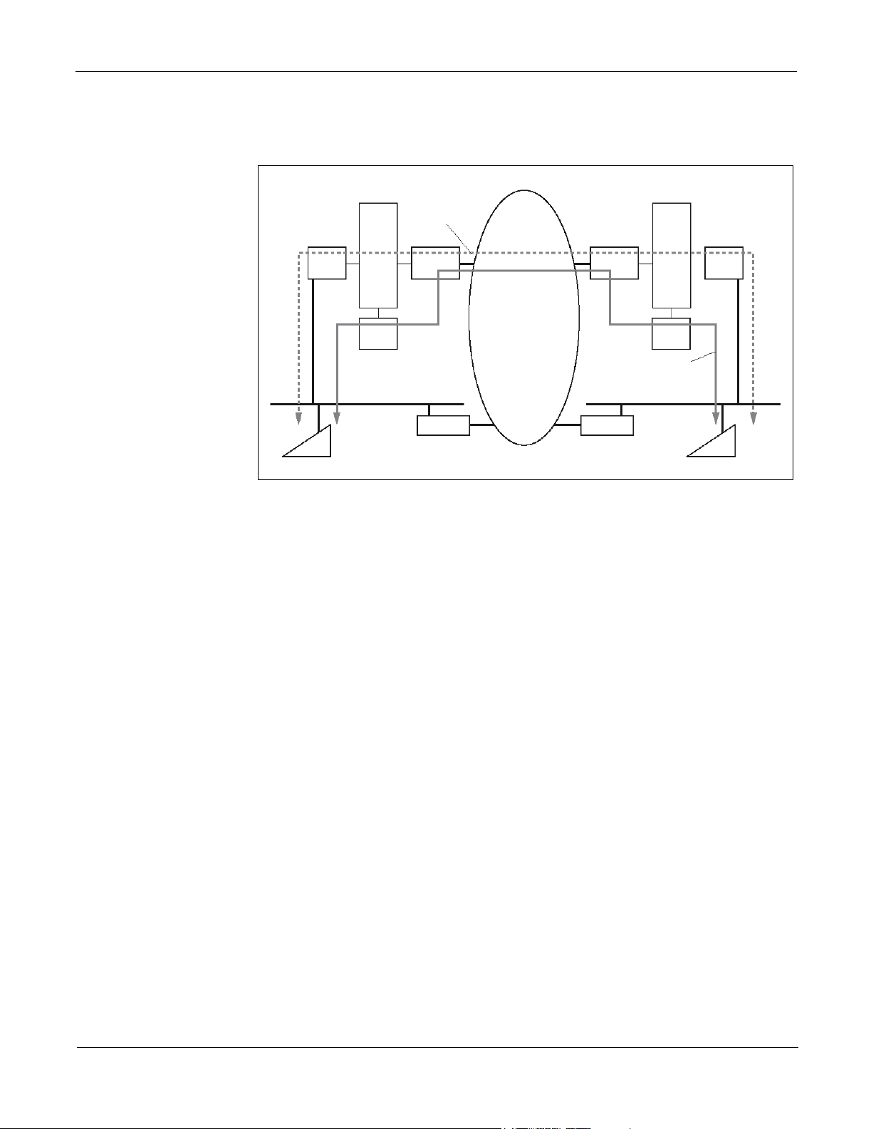
H.323 Connection For Dterm IP-to-Dterm IP connection via the IP network with H.323 protocol, the IPT
card is required to transmit and receive the control signal and voice data.
TDSW
IP-PAD
MP
LAN
Dterm IP
Voice Signal
H.323 IPT
ROUTER
Figure 2-8 System Outline of H.323 Connection
System Conditions
Overall System Conditions for Overall System
• To connect the MP (PN-CP24-A) card to the LAN, the ETHER (PZ-M606-A)
card is required on the MP card.
INTERNET/
INTRANET
H.323 IPT
ROUTER
TDSW
IP-PAD
MP
Control Signal
LAN
Dterm IP
• When you set or change the system data, the system data backup must be executed
• System data can be saved to the flash memory on the MP card on a daily basis.
• While saving the system data to the flash memory, the SYSD lamp on the MP
• Even though no FP cards are mounted on the system, FP Number 01-03 can be
• After executing the system data memory all clear, FP Number 00 is set to MP
• 64 ports are used per Virtual FP/AP number.
• The DTMF sender signal width of Dterm/Dterm IP is 112-128 milliseconds.
NEAX 2000 IPS Configuration Guide
NDA-24347, Issue 1
by CMEC Y=6>00. If the system is turned off or the MP card is reset without the
backup, changes to the data are not saved.
The data setting to execute the regular system data backup is required.
card flashes. Do not turn off or reset the system while the SYSD lamp is flashing
used as virtual FP by office data setting (CM08>484 is not required).
built-in FP and FP Number 01-03 are set to Signaling Converter (Virtual FP) in
default.
Page 15
Page 26

System Conditions Chapter 2 System Configuration
Peer-to-Peer Connection
Conditions for Peer-to-Peer Connection
• For communication between Dterm IP telephones, the voice data is transmitted
and received directly, without converting voice packets into PCM and voice
compression in the system.
CCIS Connection Conditions for CCIS Connection
• Dterm IP-to-Dterm IP connection (Peer-to-Peer connection) via CCIS is available
only when the destination office is NEAX 2000 IPS or NEAX 2400 IPX.
• The built-in CCH-IPT of MP card can be connected to a maximum of 127 trunks.
• The system provides only Point-to-Multipoint connection.
H.323 Connection Conditions for H.323 Connection
• When connecting to the IP network with H.323 protocol, the IPT card is required.
• When connecting to the IP network with H.323 protocol, the voice data is
transmitted and received via the IP-PAD card.
IP-PAD Conditions for IP-PAD
• When the FP type is designated as Signaling Converter (Virtual FP) by CM05
Y=6, the IP-PAD card cannot operate in the system.
Device Registration Server (DRS)
Legacy Interface (LT/AP)
• The IP-PAD card number depends on the mounting location on the PIM.
• To use a 32-channel PAD, two VCT cards are required per IP-PAD card. When
mounting one VCT card per IP-PAD card, a 16-channel PAD is available.
• The IP-PAD card uses 32 channels/ports, even if mounting one VCT card per
IP-PAD card.
• Do not pull out the VCT card from the PIM or IPTRK BUS CA cable from the IP
PAD/VCT card while the MP card is in on-line mode. If the VCT card or IPTRK
BUS CA is pulled out in on-line mode, the IP-PAD card operates abnormally.
Conditions for Device Registration Server (DRS)
• System-based DRS executes the Dterm IP registration.
• Network-based DRS is not available for the Dterm IP registration.
• Network-based DRS can be used as the Proxy server.
Conditions for Legacy Interface (LT/AP)
• All Application Processor cards used in NEAX 2000 IVS/IVS2 except AP01 and
CC01 cards are available for the system.
• All Line/Trunk cards used in NEAX 2000 IVS/IVS2 are available for the system.
• When the Virtual FP/AP is set by CM05 Y=0, Line/Trunk cards cannot operate
even though the card is mounted on the corresponding PIM.
NEAX 2000 IPS Configuration Guide
Page 16 NDA-24347, Issue 1
Page 27

Chapter 2 System Configuration Mounting IP-PAD Card
Maintenance Conditions for Maintenance
• MATWorX can be used as the maintenance program for NEAX 2000 IPS. Direct
connection (RS-232C), Modem connection and LAN (TCP/IP) connection are
available to connect to the Maintenance Administration Terminal (MAT).
• When using the MATWorX Version 3 or later, the message (OK) for completion
of system data memory all clear is not displayed on the MOC window.
• You can check the condition of LAN cable connection by transmitting the PING
packet to the ETHER card from PC on the LAN.
IP-PAD/VCT Card Cautions for Unplugging/Plugging IP-PAD/VCT Card
• The IP-PAD card must be plugged in or unplugged under Make Busy condition or
power off to prevent damages from occurring to the card or other system circuitry.
• Turn ON the MB switch on the IP-PAD card before the following operations:
• Resetting the MP (MP built-in FP)/FP card controlling the IP-PAD cards
• Inserting or extracting the VCT cards during on-line
• Plugging or unplugging the BUS cable (IPT TRK BUS CA) between the IP-
• After the above operations, turn OFF the MB switch.
• Be sure to insert all of the VCT cards firmly into their slots, which are connected
to the IP-PAD card by the BUS cable. Otherwise, the IP-PAD card connected to
the VCT card will not operate normally.
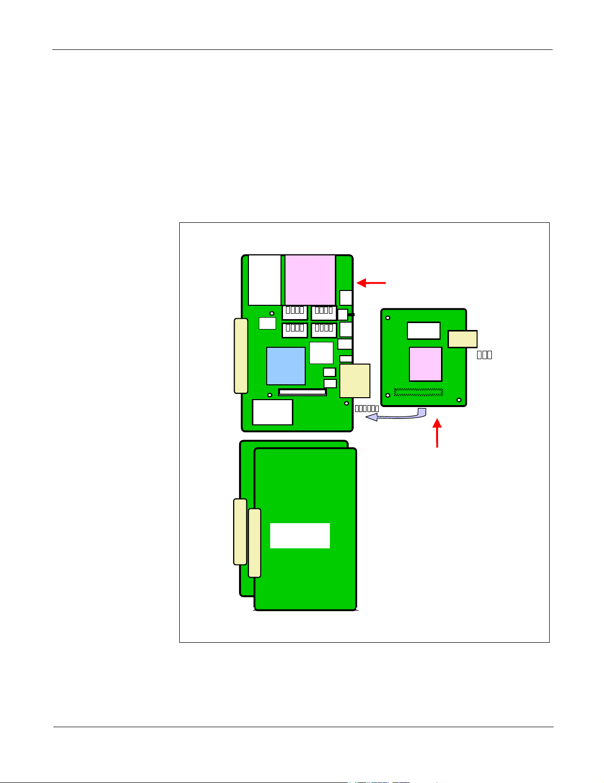
Mounting IP-PAD Card
1. Before mounting the IP-PAD (PN-32IPLA) card, set the MB switch to UP
position, and set the other switches to their correct positions.
2. Mount the IP-PAD card in one of the following LT slots of PIM 0 - PIM 7.
Maximum of two IP-PAD cards per MP built-in FP/FP, maximum of eight per
system can be mounted.
• LT00, LT01 in PIM 0/2/4/6: Card Number 0
• LT04, LT05 in PIM 0/2/4/6: Card Number 1
• LT00, LT01 in PIM 1/3/5/7: Card Number 2
• LT04, LT05 in PIM 1/3/5/7: Card Number 3
PAD and VCT cards
Note 1: One IP-PAD card requires two physical slots and two vacant slots.
Note 2: Do not mount any other L/T cards in the LT08-LT11 slots when you mount the
NEAX 2000 IPS Configuration Guide
NDA-24347, Issue 1
IP-PAD card in the LT05 slot.
Page 17
Page 28
Mounting IP-PAD Card Chapter 2 System Configuration
PIM 0/2/4/6
PFT
MP12/FP12
LT11
LT10
LT09
LT08
LT07
LT06
LT05
LT04
LT03
LT02
LT01
LT00
VM
IP-PAD
Card
No. 0
IP-PAD IP-PAD L/T must not
LT02
LT01
LT00
VM
IP-PAD
Card
No. 2
LT03
IP-PAD
Card
No. 1
PIM 1/3/5/7
LT05
LT04
IP-PAD
Card
No. 3
Note NoteNote Note
be mounted
LT08
LT07
LT06
LT11
LT10
LT09
PFT
Note NoteNote Note
IP-PAD IP-PAD L/T must not
be mounted
Figure 2-9 Mounting IP-PAD Card
Note: This slot must be vacant except for the VCT card.
For the IP-PAD card, the card number must be assigned by the system data
programming according to the PIM and slot, which accommodates the card.
3. After mounting the card, set the MB switch to DOWN position to put the card in
service.
NEAX 2000 IPS Configuration Guide
Page 18 NDA-24347, Issue 1
Page 29

Chapter 2 System Configuration Mounting VCT Card
Mounting VCT Card
1. Set the card number to each VCT (PN-16VCTA) card by SW 1 setting, and
confirm the correct switch settings.
2. Mount the first VCT (VCT 0) card in the LT slots, next to the IP-PAD card
mounted in the previous procedure.
3. Mount the second VCT (VCT 1) card in the LT slots, next to the VCT 0 card.
PIM 0 - 7
PFT
MP12/FP12
LT11
LT10
LT09
LT08
LT07
LT06
LT05
LT04
LT03
LT02
LT01
LT00
VM
V
V
C
IP-PAD IP-PAD
C
T
T
V
V
C
C
T
T
11 11
IP-PAD IP-PAD L/T must not
VCT VCT
Note NoteNote Note
be mounted
Figure 2-10 Mounting VCT Card
Note 1: This slot must be vacant except for the IP-PAD card.
Note 2: Do not mount any other L/T cards in the LT08-LT11 slots when you mount the
VCT card in the LT06 and LT07 slots.
NEAX 2000 IPS Configuration Guide
NDA-24347, Issue 1
Page 19
Page 30

Mounting Conditions of IP-PAD/VCT Card Chapter 2 System Configuration
Mounting Conditions of IP-PAD/VCT Card
When accommodating the IP-PAD and the VCT card, you must provide vacant slots as shown in Table 2-1. Those
vacant slots can be located in any LT slots on the PIM and are not available for any Line/Trunk or Application
Processor cards.
Table 2-1 IP-PAD/VCT Card Mounting Conditions
PIM
PIM
0, 2,
4, 6
PIM
1, 3,
5, 7
NUMBER
OF
CHANNELS
16
32
48
64
16
32
48
NUMBER OF CARDS REQUIRED SLOTS
IP-PAD VCT
1
(Card Number 0)
1
(Card Number 0)
2
(Card Number 0, 1)
2
(Card Number 0, 1)
1
(Card Number 2)
1
(Card Number 2)
2
(Card Number 2, 3)
1
2
3
4
1
2
3
NUMBER
OF SLOTS
IP PAD : 2
VCT : 1
Vacant : 1
IP PAD : 2
VCT : 2
Vacant : 0
IP PAD : 4
VCT : 3
Vacant : 1
IP PAD : 4
VCT : 4
Vacant : 0
IP PAD : 2
VCT : 1
Vacant : 1
IP PAD : 2
VCT : 2
Vacant : 0
IP PAD : 4
VCT : 3
Vacant : 1
MOUNTING SLOT
LT00-LT01
LT02
LT03
LT00-LT01
LT02, LT03
LT00-LT01, LT04-LT05
LT02, LT03, LT06
LT07
LT00-LT01, LT04-LT05
LT02, LT03, LT06, LT07
LT00-LT01
LT02
LT03
LT00-LT01
LT02, LT03
LT00-LT01, LT04-LT05
LT02, LT03, LT06
LT07
ADDITIONAL
SLOTS
NUMBER
8
(LT05 - LT11)
LT/AP
8
(LT05 - LT11)
LT/AP
4
(LT08 - LT11)
AP Only
4
(LT08 - LT11)
AP Only
8
(LT05 - LT11)
LT/AP
8
(LT05 - LT11)
LT/AP
4
(LT08 - LT11)
AP Only
64
Page 20 NDA-24347, Issue 1
(Card Number 2, 3)
2
4
IP PAD : 4
VCT : 4
Vacant : 0
LT00-LT01, LT04-LT05
LT02, LT03, LT06, LT07
NEAX 2000 IPS Configuration Guide
4
(LT08 - LT11)
AP Only
Page 31

Chapter 2 System Configuration BUS Cable Connection between IP-PAD and VCT Cards
BUS Cable Connection between IP-PAD and VCT Cards
Connect the VCTB/VCTA connector on the IP-PAD card and the VCT1A/VCT0A
connector on the VCT card by the IPTRK BUS CA, as shown below.
When two VCT cards are mounted, connect the VCT1B/VCT0B connector on the
VCT card with the VCT1A/VCT0A connector on the next VCT card, one after
another.
IP-PAD
VCTB
VCTA
VCT
VCT1B
VCT0B
VCT1A
VCT0A
LAN
VCT
VCT1B
VCT0B
VCT1A
VCT0A
To Dterm IP via LAN
To Internet/Intranet via LAN
IPTRK BUS CA
[0.33 ft. (0.1 m)]
Note
IPTRK BUS CA
[0.33 ft. (0.1 m)]
Note
Figure 2-11 IP-PAD BUS Cable Connection
Note: The IPTRK BUS CA consists of a set of three identical cables. Make sure to
NEAX 2000 IPS Configuration Guide
NDA-24347, Issue 1
connect the IP-PAD and VCT cards by using this set of cables, confirming that
connecting location of each cable must be matched in both IP-PAD and VCT
cards, as shown in Figure 2-11.
Page 21
Page 32

LAN Cable Connection of IP-PAD Card Chapter 2 System Configuration
LAN Cable Connection of IP-PAD Card
Connect the LAN connector on the IP-PAD card and the Switching HUB by using a
100 BASE-TX cable.
IP-PAD
100 BASE-TX Cable
LAN
Maximum 328 ft. (100 m)
Switching HUB
8 Not used
7 Not used
6 RD5 Not used
4 Not used
3 RD +
2 TD 1 TD +
Pins (RJ-45 Connector)
Pins (RJ-45 Connector)
Figure 2-12 IP-PAD - Switching HUB Cable Connection
NEAX 2000 IPS Configuration Guide
Page 22 NDA-24347, Issue 1
Page 33

Chapter 2 System Configuration LAN Cable Connection of ETHER Card
LAN Cable Connection of ETHER Card
Connect the LAN connector on the ETHER card and the Router/Switching HUB by
using a 10 BASE-T/100 BASE-TX cable.
When the system provides Dterm IP/OAI terminal/MAT on the LAN, connect them to
Switching HUB, which is connected to the LAN connector on the ETHER card.
ETHER
Router/Switching HUB
100 BASE-TX Cable
LAN
8 Not used
7 Not used
6 RD 5 Not used
4 Not used
3 RD +
2 TD 1 TD +
Pins (RJ-45 Connector)
Pins (RJ-45 Connector)
Maximum 328 ft. (100 m)
Dterm IP
OAI
MAT
Figure 2-13 ETHER - Router/Switching HUB Cable Connection
Note: The port number of the NEAX 2000 IPS for OAI is fixed to 60030 and for MAT
is fixed to 60000.
NEAX 2000 IPS Configuration Guide
NDA-24347, Issue 1
Page 23
Page 34

This page is for your notes.
NEAX 2000 IPS Configuration Guide
Page 24 NDA-24347, Issue 1
Page 35

Chapter 3 Module and Installation Hardware
The NEAX 2000 IPS is comprised of up to eight Port Interface Modules (PIMs).
For installing the PIMs in various installation methods, additional installation
hardware is required. (Refer to the Installation Hardware section.)
Modules
Port Interface Module (PIM)
A PIM provides 13 card slots for Common Control, Line/Trunk (LT), and Application
Processor (AP) cards. It also houses an AC/DC Power Supply, DC/DC Power Supply
(for -48 V), and batteries for protection from short-term (about 30 minutes) power
interruption.
Four champ connectors for Line/Trunk (LTC 0 to 3) are located at the lower front side
of the PIM.
A PIM provides a maximum of 12 card slots for Line/Trunk (LT) and Application
Processor (AP) cards. At maximum configuration, the system is comprised of eight
PIMs.
PIMMD
(PIM 3)
PIMMD
(PIM 2)
PIMMD
(PIM 1)
PIMMD
(PIM 7)
PIMMD
(PIM 6)
PIMMD
(PIM 5)
NEAX 2000 IPS Configuration Guide
NDA-24347, Issue 1
PIMMD
(PIM 0)
Figure 3-1 Unit Configuration
PIMMD
(PIM 4)
Page 25
Page 36

Modules Chapter 3 Module and Installation Hardware
Figure 3-2 shows the face layout of the PIMMD.
Number of ports available per slot
8-Port Card Mounted
4-Port Card Mounted
8 8 8 8 8 8 8 8 0 * 0 * 0 * 0*
4 4 4 4 4 4 4 4 4 4 4 4
*Note 2
AC/DC
Power
DC/DC
-48 V
Va cant
Space
for
AD-8
00
01
02 03
04
05 06
07
08 09
10
11
12
M
P
/
F
P
Note 1
Figure 3-2 PIMMD Face Layout
Slot 00 - Slot 11
• Line/Trunk circuit card mounting slots
• Slot 00 - Slot 07: All Line/Trunk circuit cards can be mounted.
• Slot 08 - Slot 11: 4-port circuit cards can be mounted only when 8-port cards
are not mounted in the slot 04 to 07.
• Application circuit card mounting slots
8
P
F
T
Note 3
• Slot 00 - Slot 11: All application circuit cards can be mounted.
• MP/FP: PN-CP24-A/PN-CP15 mounting slot
• AC/DC power: PZ-PW121 mounting position
• DC/DC (-48 V) power: PZ-PW122 mounting position
Note 1: When the system is comprised of three PIMs or more, FP is required. FP is
mounted in Slot 12 of PIM 2, PIM 4 and PIM 6.
Note 2: When an 8-port card is mounted in Slot 04-07, Slot 08-11 can only be mounted
with the AP cards.
Note 3: Only 8PFT card can be mounted in this space. Other cards cannot be
mounted.
Note 4: It is recommended that the LT00 slot should be used to mount the PZ-VM00-M
(AD-8) card, if provided.
NEAX 2000 IPS Configuration Guide
Page 26 NDA-24347, Issue 1
Page 37

Chapter 3 Module and Installation Hardware Installation Hardware
Battery Module (BATTM)
The BATTM is an optional module for installing optional long-term backup batteries.
These batteries provide backup protection for approximately three hours. The
BATTM is designed to accommodate batteries covering up to a 4-PIM system (two
BATTMs support maximum system configuration).
The BATTM is available for Floor-standing Installation. (When the system is a
Wall-mounting/19-inch Rack-mounting configuration, the BATTM cannot be
installed with the PIM.)
Table 3-1 Modules
ABBR. NAME CODE
PIMMD SN1617 PIMMD 150018 PIM 0 ~ PIM 7
BATTM SN1619 BATTMB 151120
Note: For the purpose of simplifying orders, a PIM includes AC/DC Power Card
and Power Cable.
PART
NUMBER
REMARKS
One per stack.
Maximum of two per system.
Installation Hardware
Base/Top Assembly
Hanger Assembly Hanger Assembly is used for Wall-mounting Installation. One set of Hanger
19-inch Bracket The 19-inch Bracket is a set of hardware used for 19-inch Rack-mounting Installation.
The Base/Top Assembly includes a Base Unit and a Top Cover for the PIM. One
Base/Top Assembly is required for each PIM stack.
Assembly is required for each PIM. Refer to Figure 3-4 for drawings of
Wall-mounting Installation.
• 19-inch Rack Bracket (A) is installed at both sides of the PIM. One set of 19-inch
Bracket (A) is required for each PIM.
• 19-inch Rack Bracket (B) is installed at the base of stack. One set of 19-inch
Bracket (B) is required for each stack.
If the system contains two PIMs or more with 19-inch Bracket (B), one set of 19-inch
Bracket (A) is also required for the top PIM.
Refer to Figure 3-5 and Figure 3-6 for drawings of 19-inch Rack-mounting
Installation.
Optional Bracket A Mounting Bracket is used for Floor-standing Installation. Without a Mounting
Bracket, 1.1 G shockproof is provided for a 1- to 3-PIM stack, and 0.5 G shockproof is
provided for a stack of four or more PIMs. To enhance the shockproof capability to
NEAX 2000 IPS Configuration Guide
NDA-24347, Issue 1
Page 27
Page 38

Installation Hardware Chapter 3 Module and Installation Hardware
1.1 G, one set of Mounting Bracket is required for each stack of four or more PIMs
and attached to the top PIM. (Optional)
An I/F Bracket is used for Floor-standing Installations to join the neighboring top PIM
in a configuration of six PIMs or more. One set of I/F Bracket is required for multiple
stacks. (Optional)
A Base Tray Assembly is used for Floor-standing Installations (UL compliant).
One Base Tray Assembly is required for each stack. (Optional)
Table 3-2 Installation Hardware
ABBR. NAME CODE
NEAX 2000
Front Cover
IPS Front
Cover Kit
Name Plate
Base/Top
ASSEM
Hanger ASSEM
Cover Parts
ASSEM-A
SN1545
BASERE
Hanger
ASSEM (UL)
19-inch Rack
Bracket (A)
19-inch Bracket
19-inch Rack
Bracket (B)
Mounting
Bracket
I/F Bracket
Mounting
Bracket
I/F Bracket
ASSEM
PART
NUMBER
151346
151347
NEAX 2000 IPS Front Cover (Blue)
Left Top Cover Triangle/Name Plate
Left Top Cover Triangle/Name Plate
QUANTITY
151109 One per Stack
151373
151369
151371
One per PIM
(Wall-mounting Installation)
One per PIM
(19-inch Rack-mounting Installation)
One per Stack
(19 inch Rack-mounting Installation)
151372 One per Stack (Optional)
151374 One per System (Optional)
Base Tray
Note: For the purpose of simplifying orders, a Base/Top ASSEM includes a Power
Base Tray
ASSEM
151375 One per Stack (Optional)
cable for PIM 0 and Label.
NEAX 2000 IPS Configuration Guide
Page 28 NDA-24347, Issue 1
Page 39

Chapter 3 Module and Installation Hardware Installation Hardware
COVER PARTS
TOP COVER
PIM
NEAX 2000 IPS Configuration Guide
NDA-24347, Issue 1
Figure 3-3 Floor-standing Installation
BASE
Page 29
Page 40

Installation Hardware Chapter 3 Module and Installation Hardware
HANGER ASSEM
HOOK
HOOK
SCREWS
PIM
BASE
FRONT
Figure 3-4 Wall-mounting Installation
NEAX 2000 IPS Configuration Guide
Page 30 NDA-24347, Issue 1
Page 41

Chapter 3 Module and Installation Hardware Installation Hardware
NEAX 2000 IPS Configuration Guide
NDA-24347, Issue 1
Figure 3-5 19-inch Rack-mounting Installation (Bracket A)
Page 31
Page 42

Installation Hardware Chapter 3 Module and Installation Hardware
BASE PLATE
Figure 3-6 19-inch Rack-mounting Installation (Bracket B)
NEAX 2000 IPS Configuration Guide
Page 32 NDA-24347, Issue 1
Page 43

Chapter 3 Module and Installation Hardware Installation Hardware
FRONT
PIM
SCREWS
Figure 3-7 Mounting Bracket
MOUNTING BRACKET
NEAX 2000 IPS Configuration Guide
NDA-24347, Issue 1
Page 33
Page 44

Installation Hardware Chapter 3 Module and Installation Hardware
SCREW
FRONT SIDE
SCREW
PIM 3
PIM 7
I/F BRACKET
Figure 3-8 I/F Bracket
NEAX 2000 IPS Configuration Guide
Page 34 NDA-24347, Issue 1
Page 45

Chapter 3 Module and Installation Hardware Installation Hardware
NEAX 2000 IPS Configuration Guide
NDA-24347, Issue 1
BASE TRAY
Figure 3-9 Base Tray Assembly
Page 35
Page 46

This page is for your notes.
NEAX 2000 IPS Configuration Guide
Page 36 NDA-24347, Issue 1
Page 47

Chapter 4 Circuit Cards
NEAX 2000 IPS Circuit Cards
NEAX 2000 IPS circuit cards are divided into the following three types. According to
these card types, the mounting location of the card and port allocation of the Time
Division Switch varies.
• Common Control Cards
• Main Processor (MP)
• Firmware Processor (FP)
• Line/Trunk (LT) Cards
• IP PAD, Line Circuit (LC), Central Office Trunk (COT), and Tie Line Trunk
(LDT/ODT)
• Application Processor (AP) Cards
• SMDR/PMS/CIS/Hotel Printer Interface (AP00)
• T1/E1 Digital Trunk Interface (DTI)
Card Location
00 01 02 03 04 05 06 07 08 09 10 11 12
L
L
L
L
L
L
L
L
L
L
L
L
T
T
T
T
T
T
T
T
T
T
T
T
0
0
0
0
0
0
0
0
0
0
1
1
0
1
2
3
4
5
6
7
8
9
0
1
/
/
/
/
/
/
/
/
/
/
/
/
A
A
A
A
A
A
A
A
A
A
A
A
P
P
P
P
P
P
P
P
P
P
P
P
0
0
0
0
0
0
0
0
0
0
1
1
0
1
2
3
4
5
6
7
8
9
0
1
LTC 0
LTC 1
LTC 2
LTC 3
Figure 4-1 PIM Face Layout
M
P
/
F
P
Champ
Connector
Number
NEAX 2000 IPS Configuration Guide
NDA-24347, Issue 1
Page 37
Page 48

Card Location Chapter 4 Circuit Cards
Table 4-1 shows the type of card mounted in each card slot.
Table 4-1 Location of Cards
SLOT NUMBER TYPE OF CARD MOUNTED
00 ~ 11
12
LT: Line/Trunk Card
AP: Application Processor Card
MP: Main Processor Card
FP: Firmware Processor Card
Note 1: IP PAD
IP Line Card (IPELC) used for IP PAD can be mounted in an 8-port LT slot
(LT00-07). The IPELC is physically two slots wide, but needs four slots
including an additional two vacant slots to support 32 LT ports. Two
16-channel CODEC cards (16VCT) can be mounted in those additional
vacant slots. Accordingly, it occupies LT00-03 and/or LT04-07.
<If one IP PAD is used>
LT or AP
PIM 0: MP
PIM 2, 4, 6: FP
PIM 1, 3, 5, 7: Not Used
00 01 02 03 04 05 06 07 08 09 10 11 12
3
2
I
P
L
1
1
6
6
V
V
C
C
T
T
LT (Maximum 32 Ports) and AP
cards can be mounted
<If two IP PADs are used>
00 01 02 03 04 05 06 07 08 09 10 11 12
1
3
2
I
P
L
1
6
6
V
V
C
C
T
T
3
2
I
P
L
1
1
6
6
V
V
C
C
T
T
AP cards can
be mounted
NEAX 2000 IPS Configuration Guide
Page 38 NDA-24347, Issue 1
Page 49

Chapter 4 Circuit Cards Card Location
Note 2: IP Trunk
The Voice CODEC card (VCT) needs to be next to the IP Trunk card (IPT) or
other VCT card due to cable length.
I
V
V
P
C
C
T
T
T
Due to power consumption, the IP Trunk card (IPT) and Voice CODEC card
(VCT) need additional vacant slots as follows. Therefore, the additional
vacant slots are not available to other LT or AP cards. 16 voice channels are
available for CCIS over IP only.
PIM CHANNELS CONFIGURATION
4 IPT + VCT 2
8 IPT + 2 VCT 3
PIM 0
12 IPT + 3 VCT 4
16 IPT + 4 VCT 5
4 IPT + VCT 0
8 IPT + 2 VCT 1
PIM 1 - 7
12 IPT + 3 VCT 2
16 IPT + 4 VCT 3
ADDITIONAL VACANT
SLOTS
NEAX 2000 IPS Configuration Guide
NDA-24347, Issue 1
Page 39
Page 50

Card Location Chapter 4 Circuit Cards
Note 3: 4BRT
The 4BRT card can be mounted in Slot 00 to Slot 11 of PIM 0 to PIM 7. When
4BRT is mounted in Slot 08-11, the last two circuits are connected from the
front side of the 4BRT card. The connection is made with connector attached
with 4BRT card. (232D-04S1B-DA5)
00 01 02 03 04 05 06 07 08 09 10 11 12
M
P
Installation cable is inserted from BWB For the first two circuits, the
installation cable is inserted
from BWB. For the last two
circuits, the cable is inserted
from front side via connector.
NEAX 2000 IPS Configuration Guide
Page 40 NDA-24347, Issue 1
Page 51

Chapter 4 Circuit Cards Common Control Cards
Common Control Cards
Table 4-2 shows a summary of the common control cards for NEAX 2000 IPS.
Table 4-2 Common Control Cards and System Software
ABBR. NAME CODE
PART
NUMBER
SPN-CP24A MP (UA)
PN-CP24-A
MP
SP-3499 IXS KUL PROG-A1
151637 MP Card
SP-3643 IPS DTG-A1
IL-C2-1-0001 CONTACT
ETHER PZ-M606-A 151492
FP PN-CP15 151409
48-Port Basic System Package
(NEAX 2000 IPS)
48-Port
System
Package
SPN-CP24 (CPU)
ICS VS PIMMD (UA)
ICS VS BASE-C (UA)
150066
MATWorX Studio
MATWorX 2000 Suite
REMARKS
Ether Card
• One per system
• For Peer-to-Peer connection and
MAT/OAI
3-/4-PIM system: One per system
5-/6-PIM system: Two per system
7-/8-PIM system: Three per system
Generic Program
• For Series 3000 software
(Release 4.2) or later
• Systems using TDM use this
basic software package
IP Starter 8-Seat System Package
(NEAX 2000 IPS)
SPN-CP24 (CPU)
ICS VS PIMMD (UA)
ICS VS BASE-C (UA)
IP Starter
Package
PZ-606-A (ETHER)
SPN-32IPLA IP PAD
64-Port System Software [Series 3000 software
(Release 4.2) or later] (FD)
Key Keeper (FD)
8-Seat License
MATWorX Studio
MATWorX 2000 Suite
64-Port System Software Package
Basic Features for:
64-Port
System
Package
64 LT Ports
Five T1’s /E1’s
Remote PIMs
Five ISDN-PRI DCH’s
48 ISDN-BRI Trunks
NEAX 2000 IPS Configuration Guide
NDA-24347, Issue 1
150065
150493
NEAX 2000 IPS with eight Dterm
IP Stations
Series 3000 software (Release 4.2)
or later
NEC Customer Software License
Agreement required
Page 41
Page 52

Common Control Cards Chapter 4 Circuit Cards
Main Processor (MP)
NAME CODE
PART
NUMBER
REMARKS
8-Seat License 150641 Licenses for 8 Dterm IP telephones
16-Seat License 150642 Licenses for 16 Dterm IP telephones
32-Seat License 150643 Licenses for 32 Dterm IP telephones
64-Seat License 150644 Licenses for 64 Dterm IP telephones
128-Seat License 150645 Licenses for 128 Dterm IP telephones
256-Seat License 150646 Licenses for 256 Dterm IP telephones
Major specifications and functionality of the MP are shown below:
Central Processing ElanSC520
System Memory Flash ROM (8 MB), SDRAM (32 MB)
Network Switching 1,024 x 1,024 Time Division Switch Note 1
MAT Interface Two RS-232C ports
Number 0 Port: Direct Connection
Number 1 Port: Remote Connection
Note 2
3-way Conference 16 sets of 3-way conference circuitry
DTMF Signal Sender 32 circuits (digit 0 to 9, *, and # are generated)
Music-on-Hold Two types are available
(Melody or External Source)
Audible Tone Generator (DTG)
Phase Locked Oscillator (PLO) Two ports (Source/Receiver)
Built-in SMDR
Built-in MCI
BS00 Function
DTMF Receiver Four circuits
DAT x 2 circuits (120 seconds per circuit)
DK00 x 2 circuits (relay drive x 1, external key scan x 1)
AP01 Function
Built-in Device Registration Server (DRS)
Note 1: Refer to the Figure 4-2 for the port allocation of the Time Division Switch.
Note 2: Number 1 Port includes a built-in modem for a remote connection of the MAT.
NEAX 2000 IPS Configuration Guide
Page 42 NDA-24347, Issue 1
Page 53

Chapter 4 Circuit Cards Common Control Cards
64 Ports
128 Ports/FP
64 Ports
64 Ports
128 Ports/FP
128 Ports/FP
128 Ports/FP
64 Ports
64 Ports
64 Ports
64 Ports
64 Ports
128 Ports
128 Ports
Used for Line/Trunk (LT) cards
64 ports per PIM
512 ports per system
Used for Application Processor (AP)
cards, 256 ports per system
3-way Conference
(16 circuits)
Music-on-Hold,
Built-in Modem,
DAT, DTMF Sender,
DTMF Receiver,
Audible Tone (DTG)
NEAX 2000 IPS Configuration Guide
NDA-24347, Issue 1
128 Ports
Not Used
128 Ports
Figure 4-2 Port Allocation of Time Division Switch
Page 43
Page 54

Common Control Cards Chapter 4 Circuit Cards
Ethernet Card This card provides Ethernet interface between MP and LAN for call control of Dterm
IP telephones/CCIS over IP with another NEAX 2000 IPS/2400 IPX. It also provides
interface for MATWorX and the OAI/ACD server.
Firmware Processor (FP)
The FP provides supervision and status analysis of Line/Trunk ports, which reside in
the PIM. The FP card is installed in Slot 12 of PIM 2, 4 and 6. The FP provides the
BUS interface for I/O BUS, PCM BUS, and Alarm BUS in a multiple-PIM
configuration.
NEAX 2000 IPS Configuration Guide
Page 44 NDA-24347, Issue 1
Page 55

Chapter 4 Circuit Cards Line/Trunk (LT) Card s
Line/Trunk (LT) Cards
Table 4-3 shows a summary of the Line/Trunk (LT) cards for NEAX 2000 IPS. The LT cards may be installed in
Slot 00 to 11 of PIM 0-7, with the following conditions:
• Maximum 64 ports per PIM
Table 4-3 Line/Trunk (LT) Cards
ABBR. NAME CODE
SPN-32IPLA IP PAD
SC-3013 IXS IP PAD PROG-A1
IP PAD
SPN-16VCTA IP PAD
IP-TRK BUS CA
SP-3636 VCTA VC PROG-A
PN-8LCAA 150114 8
PN-4LCD-A 150216 4
LC
PART
NUMBER
PORT REMARKS
151227 32
151226 0
IP Interface Card
•For IP PAD
• Maximum of two without FP system
• Maximum of two per FP system
• Maximum of eight per system
16-channel CODEC Card
•For IP PAD
• Maximum of two per 32IPLA card
• Minimum of one 16VCT is required per
32IPLA.
8-line Analog Line Circuit
• Message Waiting Control: Eight circuits
• Momentary Open: Eight circuits
• Loop Resistance: Maximum 600 Ω
including telephone set
4-line Analog Line Circuit
• Message Waiting Lamp Control
• Momentary Open: One circuit
• Loop Resistance: Maximum 600 Ω
including telephone set
PN-4LLCB 151220 4
NEAX 2000 IPS Configuration Guide
NDA-24347, Issue 1
4-line Long Line Circuit
• Works in either mode:
• Long Line Station
• Caller ID
• Loop Resistance: Maximum 2,500 Ω
including telephone set
• PZ-PW122 is required.
Page 45
Page 56

Line/Trunk (LT) Cards Chapter 4 Circuit Cards
Table 4-3 Line/Trunk (LT) Cards (Continued)
ABBR. NAME CODE
PN-8DLCP 150223 8 8-line Digital Line Circuit
PN-4DLCM 150218 4 4-line Digital Line Circuit
DLC
PN-4DLCQ 150219 4 4-line Digital Line Circuit
PN-2DLCN 150224 2
ILC
SPN-2ILCA
SP-566 BCS PAD PROG-A
PN-8COTS 150113 8
PN-8COTQ 150116 8
COT
PN-4COTB 150100 4
PART
NUMBER
PORT REMARKS
2-line Digital Line Circuit (Long Line)
• Maximum 2788.7 ft. (850 m)
(Dterm 16D)
150208 8 2-line ISDN Line Circuit
8-line Central Office Trunk
(Ground Start/Loop Start)
8-line Central Office Trunk
• For Caller ID
(Loop Start)
4-line Central Office Trunk
(Ground Start/Loop Start)
4-line Central Office Trunk
PN-4COTG 150107 4
• For Caller ID
(Loop Start)
2-line E&M Trunk
• Works in either mode:
ODT PN-2ODTA 150102 2
• 2-line 2-Wire E&M Trunk
• 2-line 4-Wire E&M Trunk
DID PN-4DITB 150104 4 4-line Direct Inward Dialing Trunk
8RST PN-8RSTG Note 151289 8 8-circuit PB Receiver
ID Number Sender
4RST PN-4RSTF 151221 4
• For Caller ID (for SLT)
• Maximum of four per system.
6-/10-Party Conference Trunk with Amp
CFT PN-CFTB 150120 10
• 6-party (one CFTB card): 10 ports
• 10-party (two CFTB cards): 20 ports
NEAX 2000 IPS Configuration Guide
Page 46 NDA-24347, Issue 1
Page 57

Chapter 4 Circuit Cards Line/Trunk (LT) Card s
Table 4-3 Line/Trunk (LT) Cards (Continued)
ABBR. NAME CODE
DAT PN-4DATC 150015 8
PART
NUMBER
PORT REMARKS
4-circuit Digital Announcement Trunk
• Maximum of 120 seconds each.
TNT PN-TNTA 151210 4 2-line Tone Trunk
AMP PN-2AMPA 151211 4 Amplifier Trunk
4-channel CODEC Card
• For IP Trunk VoIP
(CCIS/ Point-to-Multipoint)
• For connection with NEAX 2000
2
/NEAX 2400 IMX without
IVS
VCT
SPN-4VCTI-A
IP TRK BUS CA
SC-2915 IXS VCT PROG-B2
150133 4
Peer-to-Peer connection
SPN-4VCTI-B
IP TRK BUS CA
SC-2969 IXS VCT PROG-C1
150136 4
4-channel CODEC Card
• For IP Trunk VoIP
(H.323)
ZT Interface
SPN-2CSIA
SP-3174 BSI PROG-A
150213 8
• For S-Interface
• Maximum eight per PIM
• PZ-PW122 is required.
CSI
ZT Interface
SPN-2CSIH
SP-3174 BSI PROG-A
151224 8
• For U-Interface
• Maximum eight per PIM
• PZ-PW122 is required.
Optical
Modem
PN-M10 150228 0
DK00 PN-DK00 151203 0
NEAX 2000 IPS Configuration Guide
NDA-24347, Issue 1
Optical Interface Card
• For DTI/CCIS/Remote PIM
connections.
• One PN-M10 accommodates two
DTI/CCT/DAI links.
External Relay Contact Control/Scanning
(eight circuits per card)
• Works in either mode:
Control Scanning
8-circuit 0-circuit
4-circuit 4-circuit
0-circuit 8-circuit
Page 47
Page 58

Line/Trunk (LT) Cards Chapter 4 Circuit Cards
Table 4-3 Line/Trunk (LT) Cards (Continued)
ABBR. NAME CODE
PART
NUMBER
PORT REMARKS
DPC SPN-2DPCB with V11 CA 150206 4 Data Port Controller
SPN-V35 ADP with CA
M03
PN-M03
17-TW-0.3 CONN CA-A
150215 0
X.21/V35 Converter with cable
• One V35 Interface per card
DPC V35 CA
Built-in
Voice
Mail
PZ-VM00-M 151113 4
NEAXMail AD-8 with Modem
• Uses four LT Time Slots
4-port Expansion
VM01 PZ-VM01 151272 4
• For NEAXMail AD-8
• Uses an additional four LT Time Slots
Note: The PN-8RSTA has been discontinued and has been replaced by the PN-8RSTG. The PN-8RSTG requires
Series 2200 MP software (Release 3.1) or later. (PN-8RSTA does not have a minimum software
requirement.)
NEAX 2000 IPS Configuration Guide
Page 48 NDA-24347, Issue 1
Page 59

Chapter 4 Circuit Cards Application Processor (AP) Cards
Application Processor (AP) Cards
The following table shows a summary of the Application Processor cards for NEAX 2000 IPS
Table 4-4 Application Processor (AP) Cards
ABBR. NAME CODE
SPN-24DTAC-B (AP)
SC-3015 IXS PRT PROG-C1
DTI
SPN-30DTC-UA (AP)
SC-2694 SHS DTC PROG-CB
SP-3395 SHS PAD PROG-A
PRT
CCT
SPN-24PRTA-C (AP)
SC-3015 IXS PRT PROG-C1
SPN-24CCTA-A (AP)
SC-2886 IXS CCT PROG-A1
SPN-2BRTC (AP)
SC-2605 SHS BRT PROG-CF
BRT
SPN-4BRTA-A (AP)
232D-04S1B-DA5
SC-3014 IXS BRT PROG-A1
PART
NUMBER
PORT REMARKS
1.5 M-AMI Interface
151232 24
• Available up to 256 AP ports
• T1 with CSU
150106 31
2 M-AMI Interface
• Available up to 128 AP ports
151231 25 24-channel PRI Trunk PRT with CSU
150122 25 24-channel CCIS Trunk
BRA Trunk (ISDN Basic Rate Access)
150112 4
• Two BRA per card
BRA Trunk (ISDN Basic Rate Access)
151228 8
• Four BRA per card with Point-to-Point
connection only
CCH
DCH
ICH
CSH
QSIG
SPN-SC00 CCH-D (AP)
SC-2753 IXS CCH PROG-A1
SPN-SC01 DCH-C (AP)
SC-2380 SHS DCH PROG-CE
SPN-SC03B 8ICH (AP)
SC-2825 IXS ICH PROG-A1
SPN-SC03B 8CSH-A (AP)
SC-3007 IXS CSH PROG-D1
SPN-SC01 QSIG (AP)
SC-2446 SHS DCH PROG- CF
Common Channel Handler
151282 1
• For CCIS
• One per Trunk Route
151283 1
D-Channel Handler
• For ISDN Primary Rate Access
D-Channel Handler (8ICH)
151233 4
•For ILC
• One per 4 x 2ILC cards
ZT Interface Handler
151225 4
• For S/U Interface
• One to eight CS cards
151213 1 QSIG Protocol Handler
NEAX 2000 IPS Configuration Guide
NDA-24347, Issue 1
Page 49
Page 60

Application Processor (AP) Cards Chapter 4 Circuit Cards
Table 4-4 Application Processor (AP) Cards (Continued)
ABBR. NAME CODE
SPN-AP00B MRC-C (AP)
AP00
PN-AP00-B
SC-3005 IXS AP00 PROG-D1
EXMEM
Note
PZ-M537 151486 0
SPN-4RSTB-B (AP)
SC-2125 SHS MFC PROG-CB
4RST
SPN-4RSTB-911 (AP)
SC-2284 SHS MFC PROG-CD
Caller ID
Class
SPN-4RSTC (AP)
SC-2254 SHS CIR PROG-UA
SPN-IPTB-A (AP)
SC-2914 IXS IPT PROG-B2
IPT
PART
NUMBER
151229 2
151207 4
151215 4
151267 4
150132 0
PORT R E MARKS
Application Package
• For SMDR/PMS/ Hotel Printer/CCIS
Centralized SMDR
• Default data supported.
Expansion Memory
•For AP00-B
• FROM x 4 MB, RAM x 2 MB)
4-circuit MF Receiver
• For T1 MF ANI
4-circuit MF Receiver
• For Enhanced 911
4-circuit ID Number Received
• For Caller ID
IP Trunk
• For CCIS (Point-to-Multipoint)
(In case of G.729a payload 40
milliseconds: four VCT per card,
maximum 16 channels per card)
• One card per PIM
• Eight cards (maximum 127 channels) per
system
• For connection with NEAX 2000
2
/NEAX 2400 IMX (without
IVS
Peer-to-Peer connection)
IP Trunk
• For VoIP (H.323)
(In case of G.729a payload 40
SPN-IPTB-B (AP)
SC-2968 IXS IPT PROG-C1
150135 0
milliseconds: three VCT per card,
maximum 12 channels per card)
• One card per PIM
• Eight cards (maximum 96 channels) per
system
CFT
Page 50 NDA-24347, Issue 1
SPN-CFTC (AP)
SC-2883 IXS CFT PROG-A1 (A)
150125 32
32-party Conference Trunk
• One card per system
NEAX 2000 IPS Configuration Guide
Page 61

Chapter 4 Circuit Cards Application Processor (AP) Cards
Table 4-4 Application Processor (AP) Cards (Continued)
ABBR. NAME CODE
SPN-DAIA-C (AP)
SC-2553 SHS RPM PROG-CC
RMT BUS-0.6 CA-A
17-TW-0.3 CONN CA-A
SPN-DAIB (AP)
SC-2586 SHS RPM PROG-CD
Remote
PIM
SPN-DAIC (AP)
48-TW-0.2 CONN CA
SPN-AP00B DBM (AP)
SC-2972 IXS DBM PROG-A1
Wireless
Roaming
SPN-SC01 DCH-Q (AP)
SC-2154 SHS DCQ PROG-CA
PART
NUMBER
151217 2
151211 2
151212 2
151230 2
151275 1
PORT R E MARKS
T1 Interface
• For Remote PIM at main system
• Maximum three cards per main site
T1 Interface
• For Remote PIM at remote system
• One MP Slot per card
• Maximum one card per remote site
T1 Interface
• For Remote PIM at main and remote
system.
• Used to expand Time Slot capacity of the
Remote PIM.
• Maximum of 12 cards per main site
• Maximum of two cards per remote site
Database Memory
• For Wireless Roaming
• One card per system
DCH Card
• For Wireless Roaming
• One card per Tie Line Route
• Installed with DTI card
Note: The Expansion Memory is the on-board sub-memory card for the AP00-B. It provides additional memory
capacity as shown below.
SYSTEM CAPACITY WITHOUT EXPMEM WITH EXPMEM
SMDR Call Record 1,600 27,000
Note: The AP cards may be installed in Slot 00 to 11 of PIM 0-7, with the following conditions:
• Maximum 24 cards per system
• Maximum 256 ports per system
NEAX 2000 IPS Configuration Guide
NDA-24347, Issue 1
Page 51
Page 62

This page is for your notes.
NEAX 2000 IPS Configuration Guide
Page 52 NDA-24347, Issue 1
Page 63

Chapter 5 System Power Supply
AC/DC Power Supply
The AC/DC Power card is mounted in the left side of each PIM. The AC/DC Power
card provides power to all circuit cards that are installed in the PIM.
• AC power requirements are as follows:
Input Voltage: 90 to 132 Vrms or 180 to 264 Vrms (selectable by switch) 50/60
Hz
Table 5-1 AC/DC Power Card
ABBR.
PWR PZ-PW121 151488
Note: One power card (PZ-PW121) is included with each PIM. Therefore, it is not
DC/DC Power Supply
The DC/DC Power card is mounted under the AC/DC Power card and generates -48 V
power, which is used to power ancillary devices such as Wireless and Analog Caller
ID stations.
ABBR.
PWR PZ-PW122 151487
NAME
CODE
required to place a separate order for a PZ-PW121 except for spare or
replacement.
NAME
CODE
PART
NUMBER
Table 5-2 DC/DC (-48 V) Power Card
PART
NUMBER
QTY REMARKS
1
per PIM
QTY REMARKS
1
per PIM
AC/DC Power Supply
• Input: 100 V/200 V
• Output: +5 V,-27 V,+90 V, CR
DC/DC Power Supply
• Input: -27 V
• Output: -48 V
NEAX 2000 IPS Configuration Guide
NDA-24347, Issue 1
Page 53
Page 64

Battery Backup Chapter 5 System Power Supply
Battery Backup
For customers requiring battery backup, short-term and/or long-term options are
available.
Short-term Option Two 3.4AH batteries are required per PIM, and installed inside each PIM. Backup
time is approximately 30 minutes when PHS is not accommodated and approximately
ten minutes when PHS is accommodated in the system.
Long-term Option Two 24AH batteries are required per each two PIMs, and installed inside the Battery
Module in each stack. Backup time is approximately three hours when PHS is not
accommodated and approximately two hours when PHS is accommodated in the
system.
The batteries vary depending on the requested backup time.
The battery is provided locally.
Power Failure Transfer (PFT)
PZ-8PFTB
PZ-8PFTB
PFT 1 CONNECTOR
PFT 0 CONNECTOR
Figure 5-1 PZ-8PFTB Installation
CHAMP CONNECTOR ATTACHED TO PZ-8PFTB
TO MDF
25-PAIR CABLE
Table 5-3 PZ-8PFTB
ABBR.
NAME
CODE
PFT PZ-8PFTB 150119
Page 54 NDA-24347, Issue 1
PART
NUMBER
QTY REMARKS
1
per PIM
8-line PFT Card
NEAX 2000 IPS Configuration Guide
Page 65

Chapter 6 Cabling
The internal and external cabling of the NEAX 2000 IPS is as follows:
• Internal Cabling
•BUS Cable
• Power Control Cable
• DC Power Cable
• AC Power Cable
• External Cabling
• IP Connection
• Attendant Console
• MAT (RS-323C)
• Built-in SMDR/MCI on MP
• SMDR (with/AP00)/PMS/Hotel Printer Voice Messaging System (MCI)
• External Alarm Display
• Digital Trunk Interface
• Data Port Controller (DPC)
• DPC and X.21/V.35 Converter
NEAX 2000 IPS Configuration Guide
NDA-24347, Issue 1
Page 55
Page 66

Internal Cabling Chapter 6 Cabling
Internal Cabling
BUS Cable BUS cable provides a connection between PIMs for I/O BUS, PCM BUS, and Alarm
BUS extension in a multiple-PIM configuration.
PIM 3
P
W
R
PIM 2
P
W
R
PIM 1
P
W
R
PIM 0
P
W
R
PIM 7
BWB
BWB
BWB
BWB
F
P
M
P
P
W
R
PIM 6
P
W
R
PIM 5
P
W
R
PIM 4
P
W
R
BWB
BWB
BWB
BWB
Figure 6-1 BUS Cable Connection
F
P
F
P
Table 6-1 BUS Cable
SYMBOL NAME CODE
PART
NUMBER
REMARKS
A 48-TW-0.7 CONN CA 151013 2.3 ft. (0.7 m)
NEAX 2000 IPS Configuration Guide
Page 56 NDA-24347, Issue 1
Page 67

Chapter 6 Cabling Internal Cabling
Power Control Cable
The power control cable provides a connection between the MP and the AC/DC
power supply for controlling battery backup function and MJ/MN alarm indication.
Table 6-2 Power Control Cable
NAME CODE
PART
NUMBER
REMARKS
Power Control Cable
PWR CNT CA-D 151031
•For PIM 1 - PIM 7
• BWB - PZ-PW121/122
(Included in PIM)
Power Control Cable
PWR CNT CA-E 151032
•For PIM 0
• BWB - PZ-PW121/122
(Included in Base and PIM for Dual System)
Note: One power control cable is contained in the PIM or Base. It is not necessary
to order a separate power control cable except for spare or replacement.
DC Power Cable The DC power cable provides a connection between the AC/DC power supply for
extending the 27 VDC input in a multiple-PIM configuration, when battery backup
option is required.
An Internal Battery is installed in every PIM.
P
PIM 3
W
R
B
P
PIM 2
A
W
R
B
P
PIM 1
W
R
B
P
PIM 0
A
W
R
B
BASE
BATT
BATT
BATT
BATT
P
PIM 7
W
R
B
P
PIM 6
W
A
R
B
P
PIM 5
W
R
B
P
PIM 4
W
A
R
B
BASE
BATT
BATT
BATT
BATT
NEAX 2000 IPS Configuration Guide
NDA-24347, Issue 1
Figure 6-2 Power Cable Connection (Internal Battery Option)
Page 57
Page 68

Internal Cabling Chapter 6 Cabling
Table 6-3 Power Cable (Internal Battery Option)
SYMBOL NAME CODE
PART
NUMBER
REMARKS
A PWR CA-A 151008 DC Power Cable (-27 V input)
B BATT CA INT 151002 Internal Battery Cable
An External/Internal Battery is in the bottom PIM.
PIM 3 PIM 7
P
W
R
A
PIM 2 PIM 6
P
W
R
A
PIM 1 PIM 5
P
W
R
P
W
R
A
P
W
R
A
P
W
R
A
PIM 0 PIM 4
P
W
R
B
To Battery To Battery
A
P
W
R
B
Figure 6-3 Power Cable Connection (External Battery Option)
Table 6-4 Power Cable (External Battery Option)
SYMBOL NAME CODE
PART
NUMBER
REMARKS
A PWR CA-A 151008 DC Power Cable (-27 V input)
B BATT CA EXT 151003 External Battery Cable
NEAX 2000 IPS Configuration Guide
Page 58 NDA-24347, Issue 1
Page 69

Chapter 6 Cabling Internal Cabling
AC Cord The AC cord provides a connection between the AC/DC power card and base unit.
PIM 3
PIM 2
PIM 2
PIM 0
P
W
R
P
W
R
P
W
R
P
W
A
R
A
A
A
To Base Unit
P
W
R
P
W
R
P
W
R
P
W
A
R
A
A
A
PIM 7
PIM 6
PIM 5
PIM 4
To AC Commerc ial Power
B
Base Unit
Figure 6-4 AC Cord Connection
Table 6-5 AC Cord
SYMBOL NAME CODE
PART
NUMBER
REMARKS
A AC CORD-B-U 151010 AC Power Cable (Included in PIM)
B AC CORD-D-U 151033
AC Power Cable for Base (Included in Base)
NEAX 2000 IPS Configuration Guide
NDA-24347, Issue 1
Page 59
Page 70

External Cabling Chapter 6 Cabling
External Cabling
IP Connection MP with PZ-M606-A and IP PAD
MP
IP PAD
M606-A
IPELC
16VCT
16VCT
10 BASE-T/100 BASE-TX
(Local Supply)
10 BASE-T/100 BASE-TX
(Local Supply)
IP TRK BUS CA
ETHERNET
Dterm IP
Dterm IP
MATWorX (Maximum of two)
OAI Server (Maximum of four)
CCIS over IP via
IP Network
(Linked with distant
NEAX 2000 IPS)
Figure 6-5 IP BUS Cable Connection (IP PAD)
Table 6-6 IP BUS Cable (IP PAD)
NAME CODE
PART
NUMBER
REMARKS
IP TRK BUS Cable
IP TRK BUS CA 151036
• 0.33 ft. (0.1 m)
(Included in SPN-16VCTA IP PAD)
NEAX 2000 IPS Configuration Guide
Page 60 NDA-24347, Issue 1
Page 71

Chapter 6 Cabling External Cabling
IP Trunk (H.323, CCIS over IP with NEAX 2000 IVS2)
HUB/Route
10 BASE-T/100 BASE-TX
IPT
(Local Supply)
4VCT
4VCT
Figure 6-6 IP BUS Cable Connection (IPT)
Table 6-7 IP BUS Cable (IPT)
NAME CODE
PART
NUMBER
IP TRK BUS CA 151036
IP TRK BUS CA
REMARKS
IP TRK BUS Cable
• 0.33 ft. (0.1 m)
(Included in SPN-4VCTI-A, or SPN-4VCTI-B)
NEAX 2000 IPS Configuration Guide
NDA-24347, Issue 1
Page 61
Page 72

External Cabling Chapter 6 Cabling
Attendant Console Desk Console (SN716 DESKCON)
When using PN-PW00
PIM Slot 00 to 11
P
W
0
0
D
L
C
MDF
SN716
DESKCON
LTC 0
LTC 3
or
Installation Cable
with 8DLCP: Maximum 984 ft. (300 m)
with 4DLCM/4DLCQ/2DLCN: Maximum 3937 ft. (1200 m)
When using AC Adapter
PIM Slot 00 to 11
D
L
C
LTC 0
LTC 3
or
MDF
SN716
DESKCON
Installation Cable
with 8DLCP: Maximum 984 ft. (300 m)
with 4DLCM/4DLCQ/2DLCN: Maximum 3937 ft. (1200 m)
Figure 6-7 Attendant Console Cable Connection
NEAX 2000 IPS Configuration Guide
Page 62 NDA-24347, Issue 1
Page 73

Chapter 6 Cabling External Cabling
Maintenance Administration Terminal (MAT) (RS-232C)
Direct Connection
PIM
M
or
RS 1
RS 0
P
25p DSUB (F)
MAT CA-P 13.0 ft. (4 m)
MAT CA-T 6.5 ft. (2 m)
RS-232C Cable (PC)
Maximum 36 ft. (11 m)
9p DSUB (F)
Figure 6-8 MAT Cable Connection (Direct)
MAT
MAT
Table 6-8 MAT Cable (Direct)
NAME CODE
PART
NUMBER
REMARKS
MAT CA-T 151029 RS-232C Cable, 6.6 ft. (2 m)
MAT CA-P 151016 RS-232C Cable, 13.1 ft. (4 m)
NEAX 2000 IPS Configuration Guide
NDA-24347, Issue 1
Page 63
Page 74

External Cabling Chapter 6 Cabling
Remote Connection
• Remote connection is available via an internal modem in the MP or external
modem.
Remote Connection via Internal Modem
M
P
Installation Cable
MDF
PSTN
MODEM
MAT
PIM
C
O
T
LTC 0
Figure 6-9 MAT Cable Connection (Remote Connection via Internal Modem)
Note 1: The installation cable is connected to LTC 0, LTC 1, LTC 2 or LTC 3
connector depending on the installed location of the COT card.
Note 2: The MP to COT connection is made through internal switching of the Time
Division Switch.
Remote Connection via External Modem
Slot 13 25p DSUM (M)
RS 1
RS 0
RS NORM-4S CA-A 13 ft. (4 m)
M
P
MODEM
MDF
PSTN
MAT
MODEM
Figure 6-10 MAT Cable Connection (Remote Connection via External Modem)
Table 6-9 MAT Cable (Remote Connection via External Modem)
NAME CODE PART NUMBER REMARKS
RS NORM-4S CA-A 151004 RS-232C Cable, 13.1 ft. (4 m)
NEAX 2000 IPS Configuration Guide
Page 64 NDA-24347, Issue 1
Page 75

Chapter 6 Cabling External Cabling
Built-in SMDR/MCI on MP
The MP card provides RS-232C interface ports for SMDR/MCI connection.
Number 0/1 Port: Asynchronous: 1200/2400/4800/9600/19200 bps
Connection to SMDR is made on a port basis by a front cable.
PIM
or
RS NORM-4 CA-A
M
RS 0
P
or
RS 1
RS RVS-4 CA-C
25p DSUB (M)
Figure 6-11 Cable Connection for Built-in SMDR/MCI on MP
25p DSUB (F)
MODEM
MODEM
SMDR/
MCI
SMDR/
MCI
Table 6-10 Cable for Built-in SMDR/MCI on MP
NAME CODE
PART
NUMBER
RS RVS-4S CA-C 151021
RS NORM-4S CA-A 151004
REMARKS
RS-232C Cable, 13.1 ft. (4 m)
MP-DTE
RS-232C Cable, 13.1 ft. (4 m)
MP-DCE (MODEM)
NEAX 2000 IPS Configuration Guide
NDA-24347, Issue 1
Page 65
Page 76

External Cabling Chapter 6 Cabling
SMDR (with AP00)/PMS/Hotel Printer/MCI/CCIS Centralized SMDR
The PN-AP00-B card provides four RS-232C interface ports for SMDR, PMS, CIS
Printer, Hotel Printer, MCI and Centralized SMDR.
Connection to SMDR, PMS or Printer is made on a port basis by a front cable.
PIM
RS RVS-4 CA-C
RS NORM-4 CA-A
RS PRT-15 CA-A
Figure 6-12 AP00 Cable Connection
PN-AP00-B (Slot 00 to 11)
25p DSUB (M)
MODEM
MODEM
25p DSUB
SMDR/PMS/MCI25p DSUB (F)
SMDR/PMS/MCI
CIS/Hotel Printer
(M)
NAME CODE
RS RVS-4S CA-C
RS NORM-4S CA-A
RS PRT-15S CA-A
Table 6-11 Cable for AP00
PART
NUMBER
151021
151004
151007
QTY REMARKS
1
per SMDR or PMS
1
per SMDR or PMS
1
per Printer
RS-232C Cable, 13.1 ft. (4 m)
PN-AP00 - DTE
RS-232C Cable, 13.1 ft. (4 m)
PN-AP00 - DCE (MODEM)
RS-232C Cable, 49.2 ft. (15 m)
PN-AP00 - Printer
NEAX 2000 IPS Configuration Guide
Page 66 NDA-24347, Issue 1
Page 77

Chapter 6 Cabling External Cabling
External Alarm Display
The NEAX 2000 IPS can provide an optional external alarm display unit (ALM
DSPP) to indicate Power-ON/OFF, Major Alarm, and Minor Alarm status.
PIM
P
W
R
LTC0
LTC O
Power
Power Cable (locally provided)
Cable
(locally
provided)
Slot 13
M
P
Installation Cable
MDF
–27 V
ALM DSPP
PWR MJ MN
G
MJ
MN
Figure 6-13 External Alarm Display Connection
Table 6-12 External Alarm Display Panel
NAME CODE
PART
NUMBER
ALM DSPP 151300
QTY REMARKS
1
per System
External Alarm Display Panel
NEAX 2000 IPS Configuration Guide
NDA-24347, Issue 1
Page 67
Page 78

External Cabling Chapter 6 Cabling
Digital Trunk Interface (DTI)/Primary Rate Interface (PRI)/CCIS Trunk Interface (CCT)
The DTI/PRI/CCT connection is available through twisted-pair cable.
Connection via a Twisted-pair Cable
PIM Slot 00 to 11
D
T
I
LTC 0
LTC 1
Installation Cable
Installation Cable
(Twisted-pair Cable)
(Twisted-pair cable)
LTC 2
LTC 3
Figure 6-14 DTI Cable Connection (Twisted-pair Cable)
MDF
MUX
.
Digital
Network
NEAX 2000 IPS Configuration Guide
Page 68 NDA-24347, Issue 1
Page 79

Chapter 6 Cabling External Cabling
Data Port Controller (DPC)
The PN-2DPCB card provides 2-line V.11/X.21 or V.24/V.28 2-line interface ports
for data.
V.11/X21 Interface (Asynchronous/Synchronous: 600 ~ 64 kbps)
V.11/X21 Interface (Asynchronous/Synchronous: 600 - 64 kbps)
Slot 00 to 11PIM
2
D
P
C
B
DPC V11 CA 13.1 ft.
(4 m)
15p (F)
Installation Cable
MODEM
V.24/V.28 Interface (Synchronous: 600 - 19.2 kbps)
Maximum
3280 ft. (1000 m)
MODEM
DTE
Slot 00 to 11PIM
2
D
P
C
B
NAME CODE
DPC RS CA 13.1 ft.
(4 m)
Maximum
49.2 ft. (15 m)
Installation Cable
MODEM
MODEM
Figure 6-15 DPC Cable Connection
Table 6-13 DPC Cable
PART
NUMBER
DTE
REMARKS
DPC V11 CA 151014 V.11/X.21 Interface Cable, 13.1 ft. (4 m)
DPC RS CA 151017 V.24/V.28 Interface Cable, 13.1 ft. (4 m)
NEAX 2000 IPS Configuration Guide
NDA-24347, Issue 1
Page 69
Page 80

External Cabling Chapter 6 Cabling
DPC and X.21/V.35 Converter
2DPCB
M03
Figure 6-16 DPC and X.21/V.35 Converter
Table 6-14 DPC and X.21/V.35 Converter
NAME CODE
SPN-2DPCB with V11 CA
PN-2DPCB
DPC V11 CA
SPN-V35 ADP with CA
PN-M03
17-TW-0.3 CONN CA-A
DPC V35 CA
17-TW-0.3 CONN CA-A 1 ft. (0.3 m)
Maximum 49 ft. (15 m)
DPC V35 CA 13.1 ft. (4 m)
PART
NUMBER
Data Port Controller V.11 (X.21)
150206
• For 56 kbps (Synchronous)
• Distance (PN-2DPCB-DTE):
3,280.8 ft. (1,000 m)
150215 V35 Interface Card
DTE
REMARKS
NEAX 2000 IPS Configuration Guide
Page 70 NDA-24347, Issue 1
Page 81

Chapter 7 Dterm IP
Dterm IP Setup
Data setting on the Dterm IP is required in addition to the system data programming
when you start-up a Dterm IP first. Do the following setup after accommodation of
Dterm IP to the LAN and the system data programming.
When the data server (such as System-based DRS, Network-based DRS on the LAN,
DHCP Server and FTP/TFTP Server) is used, the Dterm IP must be connected to the
LAN that accommodates the servers. Connect the Dterm IP to the LAN before you
follow the procedure below.
WARNING: Do not allow unauthorized users who have not had approved
NEC training to set User Menu items and Administrator
Menu items. Dterm IP may not work if information on these
menus has been changed without the network administrator’s
knowledge.
Note: When you change only the setting on User Menu items after the Dterm IP
setup has been completed, do the following STEP 2 through STEP 7, then
press the Save key (Softkey).
When you change only the setting on Administrator Menu items after the Dterm IP
setup has been completed, do the following STEP 2 and STEP 8 through STEP 11.
STEP 1: Connect the AC adapter of the Dterm IP.
You must wait until either Parameter Missing or DRS Connect Time Out is
indicated on the LCD.
STEP 2: Hold, Transfer, *, # keys in that order.
The User Menu appears on the LCD. At this time, you can use Up and Down
softkeys to scroll the menu indication.
STEP 3: Press Hold, #, 0 keys in that order.
The Administrator Menu appears on the LCD.
STEP 4: Press 8 key.
The message of Factory Value Set? appears on the LCD.
STEP 5: Press OK key (Softkey).
The Administrator Menu appears on the LCD.
NEAX 2000 IPS Configuration Guide
NDA-24347, Issue 1
Page 71
Page 82

Dterm IP Setup Chapter 7 Dterm IP
STEP 6: Press Exit keys (Softkey).
The User Menu appears on the LCD.
STEP 7: Select the setting item by pressing digit keys, and set the required data.
Then press Set key (Softkey). When you press the Set key, the LCD returns
to the Menu indication. Repeat settings for the required items.
Table 7-1 shows the setting items on the User Menu.
Table 7-1 User Menu Items
MENU
NO.
INDICATION SETTING DATA DESCRIPTION
1: DHCP Disable
1 DHCP Mode
2: DHCP Enable
DRS Address
2
Primary
DRS Address
3
Secondary
XXX.XXX.XXX.XXX
- Not available
4 IP Address XXX.XXX.XXX.XXX
5 Default Gateway XXX.XXX.XXX.XXX
Set when the DHCP is not
used.
Set when the DHCP is
used.
Enter the IP Address of
DRS System-based.
Enter the IP Address of the
Dterm IP.
• When DHCP server is
provided for the Dterm
IP, this setting is not
required.
Enter the Default Gateway
Address.
• When the DHCP server
gives the address, or
when no Gateway (no
router) is provided, this
setting is not required.
Enter the Subnet Mask.
• When the DHCP server
6 Subnet Mask XXX.XXX.XXX.XXX
gives the Subnet Mask,
or when no Subnet
Mask is required, this
setting is not required.
NEAX 2000 IPS Configuration Guide
Page 72 NDA-24347, Issue 1
Page 83

Chapter 7 Dterm IP Dterm IP Setup
Table 7-1 User Menu Items (Continued)
MENU
NO.
7 DNS
8 VLAN
INDICATION SETTING DATA DESCRIPTION
1. DNS
Address
XXX.XXX.XXX.XXX
2. DNS
Domain
DNS Domain Name
Name
3. DRS
Name
DRS Name
1: VLAN Disable
1. VLAN
Mode
2: VLAN Enable
2. VLANIDVLAN ID
Number 2-4094
Note 3
Enter the IP Address of the
DNS server when the DNS
server is used.
Note 1
Enter the Domain Name of
the DNS server.
Enter the Domain Name of
the DRS System-based.
Set when the VLAN is not
used.
Set when the VLAN is
Note 2
used.
Enter the VLAN IP
number.
Enter the Priority number
of the VLAN.
3. VLAN
Priority
VLAN Priority
Number 0-7
• When the HUB has no
function to give priority
to a packet, no setting is
required.
9 System Information -
Note 1: For the IP Address of the DNS server, ask the network administrator.
Note 2: Only VLAN tag is available.
Note 3: Do not set the VLAN ID Number 0 and 1.
Select when displaying the
list of current settings.
STEP 8: After you finish setting User Menu items, you can start setting Administrator
Menu items. To display Administrator Menu, stay in the User Menu and
press Hold, #, 0 keys in that order. The Administrator Menu appears on the
LCD. At this time, you can use Up and Down softkeys to scroll the menu
indication.
STEP 9: Select the setting item by pressing digit keys, and set the required data. Then
press Set key. When you press the Set key, the LCD returns to the Menu
indication. Repeat settings for the required items. Table 7-2 shows the setting
items on the Administrator Menu.
NEAX 2000 IPS Configuration Guide
NDA-24347, Issue 1
Page 73
Page 84

Dterm IP Setup Chapter 7 Dterm IP
.
Table 7-2 Administrator Menu Items
MENU
INDICATION SETTING DATA DESCRIPTION
NO.
1: Normal
Set when the Dterm IP is
connected to the HUN/
Router on the LAN.
1 Dterm IP Mode
2: Remote
Set when the Dterm IP is
connected to the HUB/
Router via Internet/Intranet.
Enter the TFTP/FTP Server
2 Download Address XXX.XXX.XXX.XXX
Address when the server is
provided on the LAN.
3 LM Address - Not available
0: Automatic
1: Japan
2: Australia
3: North America
4: Others
4 Area ID
5: Hong Kong
6: Malaysia
7: Singapore
Enter your country/area ID
number.
8: England
9: Mexico
10:Taiwan
11:New Zealand
12:Korea
Enter the DRS Mate-port
1. DRS
Mate-port
2. LM
Mate-port
XXXXX
- No setting is required.
number for DRS
System-based.
Note 1, Note 2
5 Port
3. DRS
and LM
XXXXX
Self-port
4. PROTIMS
Self-port
Page 74 NDA-24347, Issue 1
XXXXX
Enter the DRS Self-port
number.
Note 1
LM Self-port setting is not
required.
Enter the DRS Self-port
number.
NEAX 2000 IPS Configuration Guide
Note 1
Page 85

Chapter 7 Dterm IP Dterm IP Setup
Table 7-2 Administrator Menu Items (Continued)
MENU
INDICATION SETTING DATA DESCRIPTION
NO.
5. RTP
Self-port
6. Voice Ctrl
Self-port
XXXXX
XXXXX
Enter the Real-time
Transfer Protocol (RTP)
Self-port number.
Enter the Voice Control
Self-port number.
Note 1
Note 1
1: Program (TFTP)
2: Program (FTP)
6 Download
3: Config (TFTP)
4: Config (FTP)
5: Program and Config
(TFTP)
Select the items 1-6 for
downloading the program
on the Dterm IP and Dterm
IP Configuration files.
6: Program and Config
(FTP)
7 Soft Reset -
Select for resetting the
Dterm IP software.
8 Factory Value - No setting is required.
Note 1: To operate the Dterm IP normally, you must not change the port number,
which has been set except when the port number needs to be changed.
Note 2: For the port number of the DRS System-based, ask the NEAX 2000 IPS
maintenance person.
STEP 10: After setting on the Administrator Menu, while displaying that menu, press
Exit key (Softkey).
The User Menu appears on the LCD.
STEP 11: Press Save key (Softkey).
The data is saved and Dterm IP is reset. The LCD returns to normal
condition.
END OF SETUP
NEAX 2000 IPS Configuration Guide
NDA-24347, Issue 1
Page 75
Page 86

Dterm IP Login/Logout Chapter 7 Dterm IP
Dterm IP Login/Logout
To connect the Dterm IP to the network, registration of the ID for each Dterm IP is
required. To provide the security, the password for Dterm IP can be registered to the
system, which administers and identifies the password.
Follow the registration procedure as shown below.
Dterm IP Login Note: The ID registration is determined by CM08>513. Before registering the ID,
program the system data.
• ID registration without password (Authentication by MAC Address)
When you start up the Dterm IP, the following appears on the LCD.
L o g i n :
C a n c e l B K O K
Figure 7-1 Dterm IP Display (ID Registration without Password)
STEP 1: Enter the station number of the Dterm IP to the first row behind Login.
After the first registration, Login operation is not required.
• ID registration with password (Login Mode)
When you start up the Dterm IP, the following appears on the LCD.
L o g i n :
P a s s w d :
C a n c e l B K O K
Figure 7-2 Dterm IP Display (ID Registration with Password)
STEP 2: Register the password to the system by CM2B.
S e t
STEP 3: Enter the station number of the Dterm IP to the first row behind Login.
STEP 4: Press Set key (Softkey).
NEAX 2000 IPS Configuration Guide
Page 76 NDA-24347, Issue 1
Page 87

Chapter 7 Dterm IP Dterm IP Login/Logout
STEP 5: Enter the password to the second row behind Passwd.
STEP 6: Press OK key (Softkey).
Time and date appears on the LCD.
Dterm IP Logout STEP 1: Go off-hook or press Speaker key.
STEP 2: Enter the logout access code assigned by CM20 or press the logout key
assigned by CM90/the softkey assigned by CM9A.
NEAX 2000 IPS Configuration Guide
NDA-24347, Issue 1
Page 77
Page 88

This page is for your notes.
NEAX 2000 IPS Configuration Guide
Page 78 NDA-24347, Issue 1
Page 89

Chapter 8 System Capacity
Main Processor (MP) System
Table 8-1 Main Processor (MP) System
ITEM
1 PIM 2 PIM 3 PIM 4 PIM 5 PIM 6 PIM 7 PIM 8 PIM
(
LT Card
AP Card
Number
(
Number
(
Number
(
Number
of Ports)
of Cards)
of Ports)
of Cards)
64 128 192 256 320 384 448 512
12 24 35 47 59 71 83 95
12 24
SYSTEM CAPACITY Note 1, Note 2
Maximum 256 ports per system
Total Number of Lines (Analog Single-line Telephone +
Dterm)
IP PAD (Number of Channels)
Standard 64 128 192 256 320 384 448 512
Analog Single-line Telephone (Lines)
Long 24 48 72 96 120 144 168 192
Standard 64 128 192 256 320 384 448 512
Dterm
Dterm IP (Peer-to-Peer Connection) Note 3 448 384 320 256 192 128 64 0
Dterm PS II 256
Zone Transceiver (ZT) 16 32 48 64 80 96 112 128
ISDN Station 16 32 48 64 80 96 112 128
Central Office Trunk (Lines)
Tie Line Trunk (Lines)
Long 24 48 72 96 120 144 168 192
Loop Start 64 128 192 256
DID with 4-DIT 48 96 144 192 240 256
LDT 24 48 72 96 120 144 168 192
2-Wire E&M 24 48 72 96 120 144 168 192
64 128 192 256 320 384 448 512
64 128 192 256
4-Wire E&M 24 48 72 96 120 144 168 192
CCIS Trunk (Peer-to-Peer Connection) Maximum 255
1.5 M - AMI DTI: 10, CCIS: 8
DTI/CCIS Digital Link Note 1
2 M - AMI Maximum eight links per system
NEAX 2000 IPS Configuration Guide
NDA-24347, Issue 1
Page 79
Page 90

Main Processor (MP) System Chapter 8 System Capacity
Table 8-1 Main Processor (MP) System (Continued)
SYSTEM CAPACITY Note 1, Note 2
ITEM
1 PIM 2 PIM 3 PIM 4 PIM 5 PIM 6 PIM 7 PIM 8 PIM
1.5 M - AMI (PRT) 8
ISDN
2BRT 12
4BRT 6 12
18 24
24
IP Trunk Note 4 1 2 3 4 5 6 7 8
PFT Connections 8 PFT 8 16 24 32 40 48 56 64
3-Party Conference Maximum 16 conference groups per system
6-Party Maximum four conference groups per system
6-/10-Party Conference
10-Party Maximum two conference groups per system
32-Party Conference Maximum eight conference groups per system
Data Port Controller (DPC) 10
20 30 40 50
DTMF Sender Maximum 32 circuits per system
DTMF Receiver 16
32
SN716 Desk Console 8
Attendant Terminal (Dterm ATT Position) Maximum eight sets per system
SMDR Interface Maximum one interface port per system
PMS Interface Maximum one interface port per system
ACD/MIS or OAI Interface Note 5 Maximum one interface port per system
Remote PIM (Number of Remote PIMs at remote site) 3
2 1 0
DID Dial Conversion 1,000
Call Forwarding-Outside Set 496
Authorization. Code/Forced Account Code/Remote Access
to System (DISA) Code
3,000
Message Remainder Set 1,024
Name Display/Guest Name Display 512
Speed Calling-Station (Station Speed Dial) Set 10,000
MP built-in SMDR Call Record 1,280
NEAX 2000 IPS Configuration Guide
Page 80 NDA-24347, Issue 1
Page 91

Chapter 8 System Capacity Main Processor (MP) System
Note 1: The maximum combined number of trunk lines and DTI channels are 256. (Each trunk line and DTI
channel is required to assign the trunk number by system data programming. The maximum value of the
system parameter for a trunk number is 256.)
Note 2: PIM in this table means Physical PIM.
Note 3: A maximum of 448 Dterm IP telephones are available.
Note 4: Maximum voice channels per IP trunk card depends on the payload size as follows (Payload size can be
assigned in system programming.):
CCIS (Point-to-Point/Point-to-Multipoint)
PAYLOAD SIZE G.729a G.711 G.723.1
20 ms 8-Channel 8-Channel ------
30 ms 16-Channel 16-Channel 16-Channel
40 ms 16-Channel 16-Channel ------
VoIP (H.323)
PAYLOAD SIZE G.729a G.711 G.723.1
20 ms 6-Channel 5-Channel ------
30 ms 8-Channel 7-Channel 8-Channel
40 ms 12-Channel 10-Channel ------
Note 5: ACD/MIS and OAI are mutually exclusive.
NEAX 2000 IPS Configuration Guide
NDA-24347, Issue 1
Page 81
Page 92

Floor-standing Installation Equipment Chapter 8 System Capacity
Floor-standing Installation Equipment
Table 8-2 Required Common Equipment for Floor-standing Installation
NO. ITEM DESCRIPTION
1
PIM PIMMD
2
TOP/BASE TOP/BASE
3
BRACKET
4
BASE TRAY
MOUNTING BRACKET
(Optional)
BASE TRAY ASSEM
(Optional)
INTERNAL
PWR CA
5
Note
PWR CA-A
BATT
EXTERNAL
BATT
BATT CA INT
(for Internal BATT)
BATT CA EXT
6
BATT CA
Note
(for External BATT)
7
MP Refer to the Equipment List
QTY
1 PIM 2 PIM 3 PIM 4 PIM 5 PIM 6 PIM 7 PIM 8 PIM
1 2 3 4 5 6 7 8
1 1 1 1 2 2 2 2
0 0 0 1 1 1 1 2
1 1 1 1 2 2 2 2
0 (1) (1) (2) (2) (3) (3) (4)
0 (1) (2) (3) (3) (4) (5) (6)
(1) (2) (3) (4) (5) (6) (7) (8)
(1) (1) (1) (1) (2) (2) (2) (2)
1 1 1 1 1 1 1 1
8
FP/BUS PN-CP15
9
BUS CABLE 48-TW-0.7 CONN CA
Note: The number of PWR CA and BATT CA are determined by the location of battery installed (inside or outside
0 0 1 1 2 2 3 3
0 1 2 3 4 5 6 7
of PIM). As for the BATT CA, it is also required to select the appropriate type. If battery backup is not
needed, these cables are not required.
NEAX 2000 IPS Configuration Guide
Page 82 NDA-24347, Issue 1
Page 93

Chapter 8 System Capacity LT/AP Card Slots
LT/AP Card Slots
Table 8-3 Number of Slots for LT/AP Cards of each PIM
MAXIMUM NUMBER
ITEM
SLOT NUMBER 00-11
TYPE OF CARD INSTALLED LT/AP MP FP/BUS
OF SLOTS USED FOR
LT AND AP CARDS
(SLOTS/SYSTEM)
1-PIM System 12 1 0 0 13
2-PIM System 24 1 0 1 26
3-PIM System 35 1 1 1 39
NUMBER OF SLOTS OCCUPIED
BY CONTROL CARDS
(SLOTS/SYSTEM)
VACANT
Note 3
TOTAL
NUMBER
OF
SLOTS
SYSTEM
CONFIGURATION
4-PIM System 47 1 1 2 52
5-PIM System 59 1 2 2 65
6-PIM System 71 1 2 3 78
7-PIM System 83 1 3 3 91
8-PIM System 95 1 3 4 104
Note 1: The LT cards shall be installed according to the following conditions:
• Maximum number of ports per PIM: 64 ports
Note 2: The AP cards shall be installed according to the following conditions:
• Maximum number of cards per system: 24 cards
• Maximum number of ports per system: 256 ports
Note 3: When the system is comprised of more than two PIMs, vacant slots exist in Slot 12 (MP Slot) of PIM 1, 3,
5, and 7.
NEAX 2000 IPS Configuration Guide
NDA-24347, Issue 1
Page 83
Page 94

Line Conditions Chapter 8 System Capacity
Line Conditions
Table 8-4 Line Conditions
Loop Resistance
Note 1
Analog Telephone Set
Loop Start Trunk
Cable Length Note 2 Standard with AC Adapter
Standard 600 Ω
Optional 2,500 Ω
Exchange Line 1,700 Ω
Tie or DID Line 2,500 Ω
8DLC 984 ft. (300 m) Note 3
Dterm 8/8D
4DLC 984 ft. (300 m) 3,937 ft. (1,200 m)
2DLC 2,789 ft. (850 m) 3,937 ft. (1,200 m)
8DLC 656 ft. (200 m) Note 3
Dterm 16D
4DLC 656 ft. (200 m) 3,937 ft. (1,200 m)
Dterm Series E
2DLC 2,789 ft. (850 m) 3,937 ft. (1,200 m)
8DLC 656 ft. (200 m) Note 3
Dterm 32D
4DLC 656 ft. (200 m) 3,937 ft. (1,200 m)
2DLC 2,789 ft. (850 m) 3,937 ft. (1,200 m)
8DLC - 984 ft. (300 m)
DSS/BLF Console
Note 4
4DLC - 3,937 ft. (1,200 m)
2DLC - 3,937 ft. (1,200 m)
Attendant Terminal Same as Dterm Series E
8DLC 984 ft. (300 m) Note 3
Operator Position
SN176
Desk Console
4DLC 1,148 ft. (350 m) 3,937 ft. (1,200 m)
2DLC 1,148 ft. (350 m) 3,937 ft. (1,200 m)
Note 1: Loop resistance includes an internal resistance of the telephone set or distant exchange.
Note 2: Cable length is based on the following conditions:
• Diameter of the cable is 0.5 mm.
• The protection arrester is not inserted between the terminal and PBX.
Note 3: When using an 8DLC card, long-line function is not available even if it is equipped with an AC Adapter.
Note 4: The DSS/BLF console requires local AC/DC supply.
NEAX 2000 IPS Configuration Guide
Page 84 NDA-24347, Issue 1
Page 95

Chapter 8 System Capacity Zone Transceiver Line Conditions
Zone Transceiver Line Conditions
Table 8-5 Zone Transceiver Line Conditions
S-INTERFACE
LINE CONDITIONS
U-INTERFACE
LINE CONDITIONS
PBX Power Supply at -48 V (Standard) 4-Wire 2-Wire 4-Wire
0.4ϕ 2,500 ft. (762 m) 2,500 ft. (762 m) 4,300 ft. (1,310 m)
0.5ϕ 4,000 ft. (1,219 m) 4,000 ft. (1,219 m) 6,900 ft. (2,103 m)
0.65ϕ 5,500 ft. (1,676 m) 5,500 ft. (1,676 m) 9,500 ft. (2,895 m)
0.9ϕ 8,000 ft. (2,438 m) 8,000 ft. (2,438 m) 13,000 ft. (3,958 m)
PBX Power Supply at -45 V Note 4-Wire 2-Wire 4-Wire
0.4ϕ 2,000 ft. (609 m) 2,000 ft. (609 m) 3,500 ft. (1,066 m)
0.5ϕ 3,200 ft. (975 m) 3,200 ft. (975 m) 5,600 ft. (1,706 m)
0.65ϕ 4,700 ft. (1,432 m) 4,700 ft. (1,432 m) 8,200 ft. (2,499 m)
0.9ϕ 7,000 ft. (2,131 m) 7,000 ft. (2,131 m) 12,200 ft. (3,718 m)
PBX Power Supply at -43 V Note 4-Wire 2-Wire 4-Wire
0.4ϕ 1,800 ft. (548 m) 1,800 ft. (548 m) 3,100 ft. (944 m)
0.5ϕ 2,900 ft. (883 m) 2,900 ft. (883 m) 5,000 ft. (1,524 m)
0.65ϕ 4,400 ft. (1,340 m) 4,400 ft. (1,340 m) 7,600 ft. (2,316 m)
0.9ϕ 6,400 ft. (1,948 m) 6,400 ft. (1,948 m) 11,000 ft. (3,352 m)
Local Power Supply (with AC Adapter)
0.4ϕ 3,900 ft. (1,189 m) 11,000 ft. (3,350 m)
0.5ϕ 4,400 ft. (1,341 m) 13,000 ft. (3,958 m)
0.65ϕ 5,500 ft. (1,676 m) 13,000 ft. (3,958 m)
0.9ϕ 8,000 ft. (2,438 m) 13,000 ft. (3,958 m)
Note: Zone Transceiver requires -48 V power under normal conditions. PBX power supply at -45 V and -43 V
shows ZT Line Conditions in the event of lower voltage status (refer to Table 8-5).
NEAX 2000 IPS Configuration Guide
NDA-24347, Issue 1
Page 85
Page 96

Traffic Capacity Chapter 8 System Capacity
Traffic Capacity
Table 8-6 Traffic Capacity
NUMBER OF PIMS 1 PIM 2 PIM 3PIM 4PIM 5 PIM 6 PIM 7 PIM 8 PIM
Traffic Capacity
Note: The maximum traffic load of each FP is 2,500 BHCA.
Maximum
2,500 BHCA
Maximum
5,000 BHCA
Note
Maximum
7,500 BHCA
Note
Maximum
8,000 BHCA
Note
System-based Device Registration Server (DRS)
Table 8-7 System-based Device Registration Server (DRS)
FEATURES OF BUILT-IN DRS DESCRIPTION REMARKS
Maximum Registration Terminals 512 ports per MP
Log-in Login without password Not Available Use blank as a password
Authentication by Network-based DRS Not Available
Authentication by System-based DRS Available
Authentication by MAC Address Available
Confirmation when overriding Available
Log-out Dialing Log-out feature access code Available
Function key Available
Softkey Available
DHCP Inter-working with DHCP server Available
TCP PORT NUMBER
MAT 60000 (Fixed)
OAI 60030 (Fixed)
NEAX 2000 IPS Configuration Guide
Page 86 NDA-24347, Issue 1
 Loading...