

Page 1

DLP Cinema® Projector
User’s Manual
DLP Cinema® Projector
NC3200S
Lamp Power Supply Unit
NC-32PS01
Page 2
2
Important Information
Precautions:
your NC3200S/NC-32PS01 and keep the manual handy for
future reference.
The NC3200S (projector unit) is called the “projector”, and the
NC-32PS01 (lamp power supply unit) is called the “lamp power
supply” in this manual.
WARNING
TO PREVENT FIRE OR SHOCK HAZARDS, DO NOT
EXPOSE THIS UNIT TO RAIN OR MOISTURE. ALSO
DO NOT USE THIS UNITユS POLARIZED PLUG WITH AN
EXTENSION CORD RECEPTACLE OR OTHER OUTLETS,
UNLESS THE PRONGS CAN BE FULLY INSERTED.
REFRAIN FROM OPENING THE CABINET AS THERE
ARE HIGH-VOLTAGE COMPONENTS INSIDE. REFER
SERVICING TO QUALIFIED SERVICE PERSONNEL.
TO REDUCE THE RISK OF ELECTRIC SHOCK, DO
NOT OPEN COVER. NO USER-SERVICEABLE PARTS
INSIDE. REFER SERVICING TO QUALIFIED SERVICE
PERSONNEL.
DOC compliance Notice
This Class A digital apparatus meets all requirements of the
Canadian Interference-Causing Equipment Regulations.
WARNING
This is a Class A product. In a domestic environment this
product may cause radio interference in which case the user
may be required to take adequate measures.
CAUTION
• In order to reduce any interference with radio and television
reception use a signal cable with ferrite core attached.
Use of signal cables without a ferrite core attached may
cause interference with radio and television reception.
• This equipment has been tested and found to comply with
the limits for a Class A digital device, pursuant to Part 15
of the FCC Rules. These limits are designed to provide
reasonable protection against harmful interference when
the equipment is operated in a commercial environment.
This e quipment g en erates, uses, and can radiate
Please read this manual carefully before using
CAUTION
RISK OF ELECTRIC SHOCK
DO NOT OPEN
CAUTION
This symbol warns the user that uninsulated
voltage within the unit may have sufficient
magnitude to cause electric shock. Therefore,
it is dangerous to make any kind of contact with
any part inside of this unit.
This symbol alerts the user that impor tant
li terat ur e con ce r ning th e op erati on and
maintenance of this unit has been included.
Therefore, it should be read carefully in order
to avoid any problems.
radio frequency energy and, if not installed and used
in accordance with the installation manual, may cause
harmful interference to radio communications.
Operation of this equipment in a residential area is likely to
cause harmful interference in which case the user will be
required to correct the interference at his own expense.
Important Safeguards
These safety instructions are to ensure the long life of your
projector and to prevent fire and shock. Please read them
carefully and heed all warnings.
Installation
1. Place the projector on a flat, level surface in a dry area
away from dust and moisture. Tilting the front of the
projector up or down from level could reduce lamp life.
Do not put the projector on its side when the lamp is
on.
Doing so may cause damage to the projector.
2. Do not place the projector in direct sunlight, near heaters
or heat radiating appliances.
3. Exposure to direct sunlight, smoke or steam could harm
internal components.
4. Handle your projector carefully. Dropping or jarring your
projector could damage internal components.
5. To carry the projector, a minimum of five persons are
required.
Do not hold the lens part and the anamorphic lens part (or
the wide converter lens part) with your hand. Otherwise
the projector may tumble or drop, causing personal
injury.
6. Do not place heavy objects on top of the projector.
Power Supply
1. The projector is so designed that it operates with the
power supply voltage described below.
• Projection Head : 0.7 kW 7A AC100-240V
50/60Hz Single-phase
• Lamp Power Supply : 9.7 kW 28A AC200-230V
50/60Hz Three-phase (Star
connection),
9.7 kW 17A AC380-415V
50/60Hz Three-phase (Star
connection)
Ensure that your power supply fits this requirement before
attempting to use your projector.
2. Consult your dealer for installing the power cable to the
projector. DO NOT install the power cable by yourself.
Doing so may cause a fire or electric shock.
3. Handle the power cable carefully and avoid excessive
bending. Do not place any heavy objects on the power
cable. A damaged cable can cause electric shock or
fire.
4. If the projector will not be used for an extended period of
time, shut down AC power.
5. Placing the power cable and the signal cable closely to
each other can cause beat noise. If this happens, keep
the two separated so that beat noise is not generated.
Beat noise is corruption of the picture often seen as a
rolling band moving through the image.
6. Do not touch the projector during a thunder storm. Doing
so can cause electrical shock or fire.
Page 3

Important Information
Cleaning
1. Shut down AC power to the projection head and the lamp
power supply before cleaning.
2. Clean the cabinet periodically with a damp cloth. If heavily
soiled, use a mild detergent. Never use strong detergents
or solvents such as alcohol or thinner.
3. Use a blower or lens paper to clean the lens, and be
careful not to scratch or mar the lens.
Fire and Shock Precautions
1. Ensure that there is sufficient ventilation and that vents
are unobstr ucted to prevent potentially dangerous
concentrations of ozone and the build-up of heat inside
your projector. Allow at least 8 inches (20cm) of space
between your projector and a wall. Allow at least 20 inches
(50 cm) of space between the ventilation outlet of the
lamp power supply and an object.
Connect the projector exhaust outlet with the exhaust
equipment having a capacity of 16m3/min or more.
2. Prevent foreign objects such as paper clips and bits of
paper from falling into your projector. Do not attempt to
retrieve any objects that might fall into your projector. Do
not insert any metal objects such as a wire or screwdriver
into your projector. If something should fall into your
projector, disconnect it immediately and have the object
removed by a qualified service person.
3. Do not place any liquids on top of your projector. Refer
servicing to qualified service personnel if liquid has been
spilled.
4.
Keep any items such as magnifying glass out of the light
path of the projector. The light being projected from the
lens is extensive, therefore any kind of abnormal objects
that can redirect light coming out of the lens, can cause
unpredictable outcome such as fire or injury to the eyes.
5. Do not cover the lens with the supplied lens cap or
equivalent while the projector is on. Doing so can lead to
distorting or melting of the cap and burning your hands
due to the heat emitted from the light output.
6. When using a LAN cable:
For safety, do not connect to the connector for peripheral
device wiring that might have excessive Voltage.
CAUTION: High Pressure Lamp May Explode if Improperly
Lamp Caution: Please read before operation
Due to the lamp being sealed in a pressurized environment,
there is a small risk of explosion, if not operated correctly.
There is minimal risk involved, if the unit is in proper working
order, but if damaged or operated beyond the recommended
hours, the risk of explosion increases. Please note that there
is a warning system built in, that displays following message
when you reach a preset operating time ユBulb Over Timeユ.
When you see this message please contact your dealer
for a replacement. If the lamp does explode, smoke will
be discharged from the vents located on the back of the
unit. Do not stand in front of the vents during the operation.
This smoke is comprised of glass in par ticulate form and
Xenon gas, and will not cause harm if kept out of your eyes.
If your eyes have been exposed to this gas, please flush
your eyes out with water immediately and seek immediate
medical attention. Do not rub your eyes! This could cause
serious injury.
Handled. Refer Servicing to Qualified Service
Personnel.
WARNING:
1. Do not look into the lens while the projector is on. Serious
damage to your eyes could result.
2.
When main body is damaged, cooling fluids may come out
of internal part. DO NOT touch and drink the cooling fluid.
When the cooling fluids are swallowed or contacted with
your eyes, please consult with doctors immediately.
CAUTION
Never unplug the projection head power plug from the outlet
or disconnect the breaker connected to the AC power cable
of the lamp power supply under the following conditions.
Doing so can damage the projector.
• While projecting images
• While cooling after the projector has been turned off.
(The POWER button LED blinks in white while the fan is
rotating, and “cooling...” is displayed on the LCD screen.
The cooling fan continues to work for 5 minutes.)
Disposing of your used product
EU-wide legislation as implemented in each
Member State requires that used electrical
and electronic products carrying the mark (left)
must be disposed of separately from normal
household waste.
This includes projectors and their electrical
accessories or lamps. When you dispose of
such products, please follow the guidance of
your local authority and/or ask the shop where
you purchased the product.
After collecting the used products, they are
reused and recycled in a proper way. This effort
will help us reduce the wastes as well as the
negative impact to the human health and the
environment at the minimum level.
The mark on the electrical and electronic
products only applies to the current European
Union Member States.
For questions relating to unclear points or repairs
Contact your dealer or the following support branch for
questions relating to unclear points, malfunctions and repairs
of the product.
In Europe
NEC Europe, Ltd. / European Technical Centre
Address: Unit G, Stafford Park 12, Telford TF3 3BJ, U.K.
Telephone: +44 1952 237000
Fax Line: +44 1952 237006
3
Page 4

Important Information
(MEMO)
4
Page 5

Table of Contents
Table of Contents ............................................................................ 5
1.What’s in the Box? and the Names of the Projector Parts ............. 6
1-1. Features ..................................................................................................................................................................... 6
1-2. What’s in the Box? .................................................................................................................................................... 8
1-3. Names of the Projector Parts ................................................................................................................................. 10
2.Installation and Connection ........................................................ 17
2-1. Steps for setting up and connecting ..................................................................................................................... 17
2-2. Connecting the image input terminals .................................................................................................................. 18
2-3. Connecting the various control terminal ............................................................................................................. 19
3.Projection of Images (Basic Operation) ....................................... 20
3-1. Steps of projecting images .................................................................................................................................... 20
3-2. Turning your projector on .......................................................................................................................................21
3-3. Selecting the title of input signal ........................................................................................................................... 23
3-4. Adjusting the position and the size of projected screen .................................................................................... 24
3-5. Preventing misoperations ...................................................................................................................................... 28
3-6. Turning on/off the lamp with the projector turned on .......................................................................................... 29
3-7. Turning your projector off ...................................................................................................................................... 30
4.Using Menus .............................................................................. 31
4-1. Basic operation with adjustment menus .............................................................................................................. 31
4-2. Table of adjustment menus .................................................................................................................................... 36
4-3. Title Select ............................................................................................................................................................... 37
4-4. Configuration .......................................................................................................................................................... 38
4-5. Title Setup ................................................................................................................................................................ 39
4-6. Information .............................................................................................................................................................. 39
5.Maintenance of Your Projector ................................................... 43
5-1. Cleaning the Cabinet .............................................................................................................................................. 43
5-2. Cleaning the Lens ................................................................................................................................................... 43
5-3. Replacing the Air Filter ...........................................................................................................................................44
6.Appendix .................................................................................... 51
6-1. Troubleshooting ...................................................................................................................................................... 51
6-2. Indicator display list ............................................................................................................................................... 53
6-3. Operation using an HTTP browser ........................................................................................................................ 55
6-4. Outline Drawing ...................................................................................................................................................... 57
6-5. Specifications ..........................................................................................................................................................59
6-6. Pin Assignment and Functions of Terminal .........................................................................................................60
6-7. Related products list .............................................................................................................................................. 68
5
Page 6

1.
What’s in the Box? and the Names of the Projector Parts
1-1. Features
• DLP Cinema® dedicated projector that supports large screen needs
NEC has applied its mounting technology and leading imaging technology to newly develop lamp and optical systems as well
as a cooling system to support large screen needs.
• Equipped with easy to use functions
(1) Lens memory function that can be operated with one touch, and lamp power memory function
The DLP Cinema
set screens sizes for each input signal. It is also provided with a lamp power memory function for storing the brightness
of the images on the screen for each input signal.
Even if you are projecting multiple images that have different settings for image sizes and brightness, you can project them
with the conditions pre-registered for each signal, simply by selecting the corresponding signal.
(2) Equipped with a lamp output control function
You can set to any brightness setting, from low brightness to high brightness. This function makes it possible to minimize
the fluctuation (*) in brightness as brightness of the lamp decreases as a result of long-term lamp usage.
* The time for maintaining fluctuations in brightness depends on the setting value for brightness.
(3) Easy lamp replacement
The lamp can be replaced from the backside of the projector, so the lamp can be easily replaced even in narrow locations
when a film projector is setup on the side and there is not much space on the projector side.
(4) Registered signal selection buttons
The projector has been equipped with new 8 signal selection buttons that make it easy to select registered signals. To this
projector, 100 titles at most can be registered (input signal registration). Among the registered titles, any 8 titles can be
assigned to the buttons <1> to <8>.
(5) Software which enables the user to operate the projector from a PC via a network is available (optional).
You can operate the projector via a network by installing the separately supplied Digital Cinema Communicator (DCC) on
your PC.
(6) Supports various contents and types of usage by applying a separately-sold multi-media switcher.
By connecting an optional multi-media switcher (MM3000B), you can input RGB/VIDEO analog signals, and digital signals
in formats not supported by the projector.
®
projector is provided with a lens memory function for storing lens zoom positions and shift positions to
6
Page 7

1. What’s in the Box? and the Names of the Projector Parts
• DMD Face Dust Protection Structure
A dust control shield is arranged between each DMD chip of R, G and B, and the spectroscopic/condenser prism to prevent
dust and dirt in the air, and oily particles in smoke associated with event halls from coming into contact with the face of the
DMD and causing operating problems.
• Efficient cooling of the heat from the DMD unit by the cooling structure
The DMD unit uses a highly efficient liquid cooling method. This efficiently eliminates heat applied to the DMD by the complete
dust control structure and high light output, thereby ensuring the reliability of the projector.
7
Page 8
1. What’s in the Box? and the Names of the Projector Parts
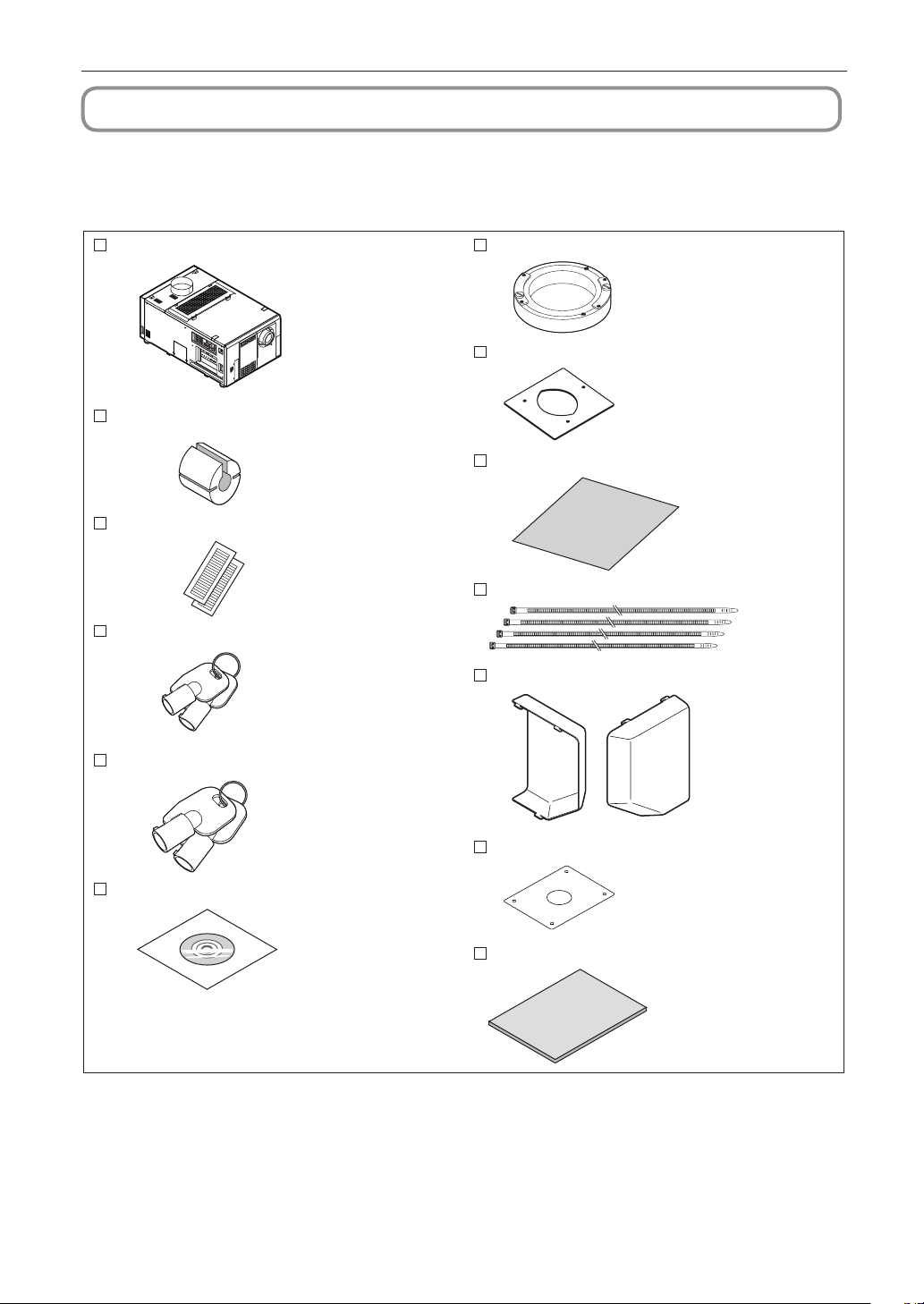
NC3200S projector
Attachm ent for l amp x 1
Sheet o f title l abels (for 20 labels ) x 2
Cover key x 2
Lamp door key x 2
CD-ROM (User’s Manual)
Lens holder (NC-PH01)
Small iris x 1
Exhaust outlet protective sheet x 1
Exhaust outlet protective sheet fastening band x 4
Air inlet cover x 2
Retainer for lamp power AC power cable x 1
Important Information x 1
1
2
3
4
5
L
A
M
P
M
E
N
U
E
N
T
E
R
D
O
U
S
E
R
K
E
Y
L
O
C
K
E
X
I
T
I
M
B
6
7
8
1-2. What’s in the Box?
Check the content of the accessories.
1-2-1. Accessories for the projector (NS3200S)
8
Page 9

1. What’s in the Box? and the Names of the Projector Parts
Lamp power supply (NC-32PS01) (with the power cable) Dedicated
interface cable x 1
TIP
1-2-2. Accessories for the lamp power supply (NC-32PS01)
In the event that you did not receive all of the accessories outlined above, or some are damaged, contact your
dealer/distributor.
Differs slightly from the drawings in this manual, but there is no problem in actual use.
9
Page 10
1. What’s in the Box? and the Names of the Projector Parts
1
2
3
4
5
L
A
M
P
M
E
N
U
E
N
T
E
R
D
O
U
S
E
R
K
E
Y
L
O
C
K
E
X
I
T
I
M
B
6
7
8
1
2
3
5
6
7
4
8
12
10
11
13
14
15
16
9
13
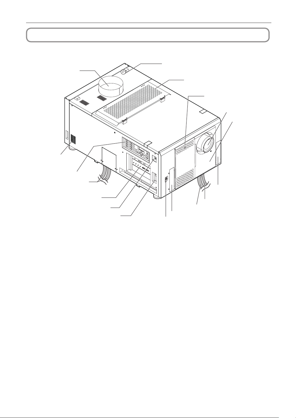
1-3. Names of the Projector Parts
1-3-1. Front of the Projector
1. Air outlet (for cooling the lamp)
Connects to an exhaust device to exhaust heat from the lamp. Please contact your dealer/distributor to install the exhaust
device.
2. Air outlet
The outlet for the heated air in the projector. Do not cover.
3. Control panel
On the control panel, power to your projector is turned on or off, titles are selected, and various adjustments are made of
projected screen. (See page 15)
4. Lamp power cable
This is the power cable that connects with the lamp power supply. Request your dealer/distributor to connect/disconnect
the power cable.
5. Connection terminals
Various image signal cable are to be connected here. (See page 14)
You can expand signal input terminals by installing the optional media block or internal multi-media switcher (MM3000B).
Contact your dealer/distributor for more information on the media block and MM3000B.
6. Main power switch
While AC power is being supplied, set the main power switch to ON, then your projector will enter a standby state.
7. Ethernet port
The connector for external devices such as a cinema server or a PC installed with the DCC. (See page 14)
8. Buzzer
The buzzer rings when the power is turned on or an error has occurred.
10
Page 11

1. What’s in the Box? and the Names of the Projector Parts
NOTE
9. Air inlet (for cooling the lamp)
The air inlet for cooling the lamp. Do not cover.
An air filter is attached over the air inlet to prevent dust. Refer to “5-3. Replacing the Air Filter” (page 44) on how to replace
the air filter.
10
. Air inlet (for cooling the projector electric circuits)
The air inlet for cooling the projector electric circuits. Do not cover.
An air filter is attached over the air inlet to prevent dust. Refer to “5-3. Replacing the Air Filter” (page 44) on how to replace
the air filter.
11
. Lens (optional)
Images are projected from the lens. Request your dealer/distributor to install or replace the lens.
12
. Interlock connector (Inside front of projector)
This is the connector for the projector safety device. This is used to control the projector from an external source. Consult
with your dealer/distributor about using this.
13
. Conversion lens stay fittings
Fittings to attach the fixing stay when using the optional conversion lens (anamorphic lens or wide converter lens). Contact
your dealer/distributor for more information on the conversion lens and fixing stay.
14.
Dedicated interface cable
This is the interface cable that connects with the lamp power supply.
15.
AC power cable (For projector)
This is the cable that supplies AC power to the projector head. The AC power cable is not an accessory. Consult with your
dealer/distributor about the AC power cable.
16
. Conversion lens stage connector terminal
The terminal to connect the control connector of the conversion lens table when using the optional conversion lens (anamorphic
lens or wide converter lens). Contact your dealer/distributor for an installation of the conversion lens.
Do not touch the air outlet and backside of the main unit when your projector is operating. Otherwise, the high
temperature may cause burns.
11
Page 12
1. What’s in the Box? and the Names of the Projector Parts
8
5
3
2
1
7
9
4
3
6
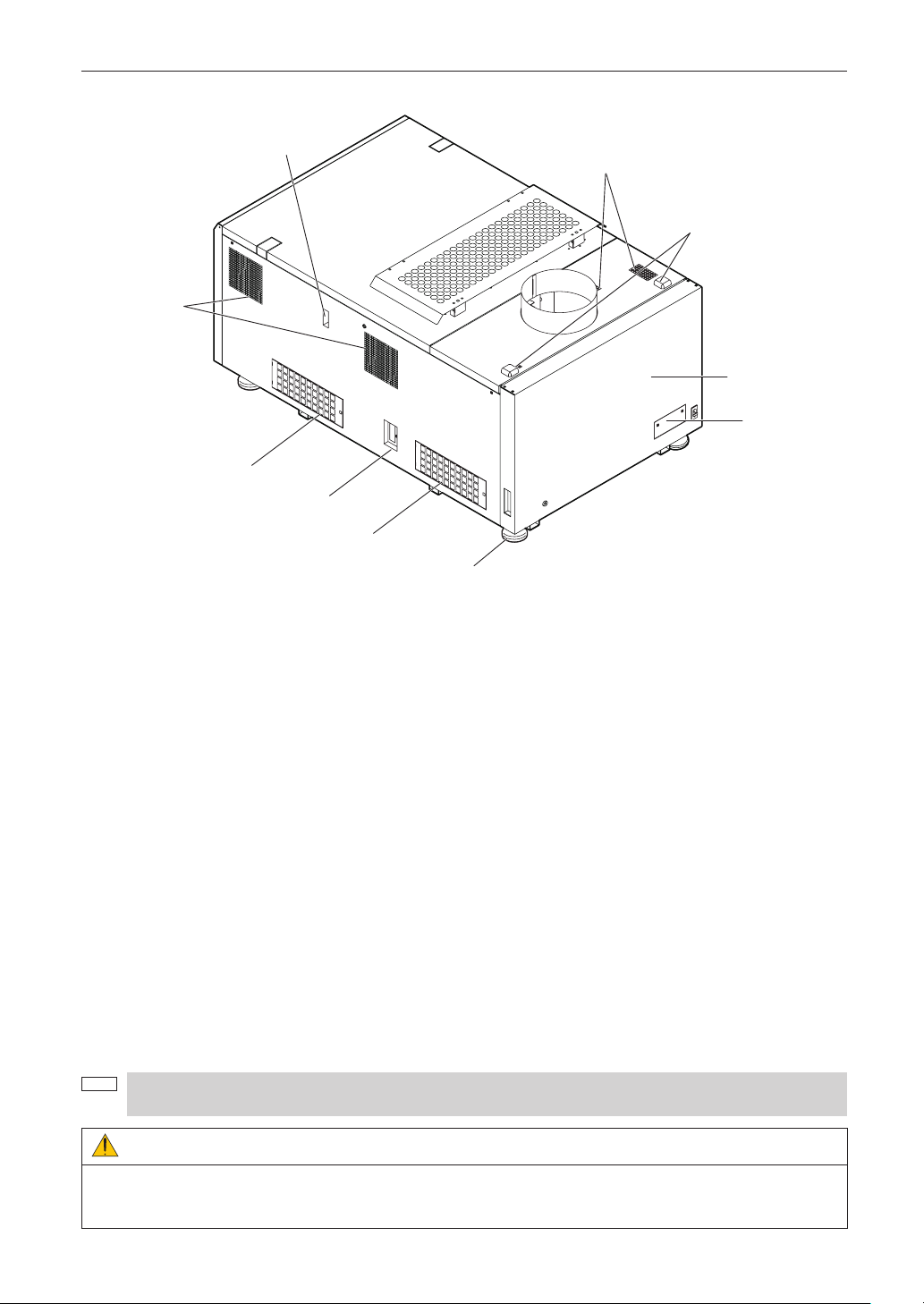
NOTE
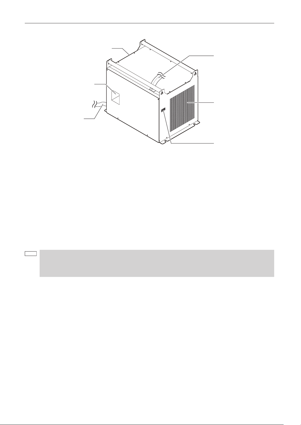
1-3-2. Rear of the projector
1. Cooling fluid gauge
The gauge to indicate the remaining amount of the DLP cooling fluid.
2. Air outlet (for cooling the projector electric circuits)
The air outlet to exhaust the heat from the projector electric circuits. Do not cover.
3. Air inlet (for cooling the projector electric circuits)
The air inlet for cooling the projector electric circuits. Do not cover. An air filter is attached over the air inlet to prevent dust.
Refer to “5-3. Replacing the Air Filter” (page 44) on how to replace the air filter.
4. Function expansion terminal connector
The connector to attach the terminal to expand the projector functions.
5. Level adjusters (in four positions on bottom)
In the ordinary installation, you can adjust the projector inclination at 4 positions.
6. Air outlet (for cooling the projector electric circuits)
The air outlet to exhaust the heat from the projector electric circuits. Do not cover.
7. Rear status indicator
These indicate the status of the projector. When the projector is operating normally, these light/blink in green or orange.
When an error occurs, they light/blink in red. When an error occurs, check the contents of the display on the LCD screen.
(See page 54)
8. Lamp door
This opens to allow the lamp to be replaced. Please contact your dealer/distributor to install and to replace the lamp bulb
and lamp house.
9. Optical axis adjustment system protection cover
The protection cover for the optical axis adjustment system (screw) for the lamp. Do not open this cover. Contact your
dealer/distributor for adjusting the optical axis.
Do not cover the air inlets and outlet while the projector is in operation. Insufficient ventilation leads to a rise of
the internal temperature and may cause a fire or malfunction.
WARNING:
Only service personnel should open the lamp door.
• The interior reaches high temperatures and there is a risk of burns.
• There is a risk of injury if the lamp is broken.
12
Page 13
1. What’s in the Box? and the Names of the Projector Parts
2
3
5
4
1 (Rear)
6
NOTE
1-3-3. Lamp power supply (NC-32PS01)
1. Air outlet
This exhausts heat from the lamp power supply.
2. Main power switch
This is the main power switch for the lamp power supply.
3. AC power cable
The AC power cable is not an accessory. Request service personnel to connect the power cable.
4. Two lamp power cables
These connect to the lamp power supply input terminals of the projector. Request service personnel to connect the power
cable.
5. Control terminal (Dedicated interface cable)
This connects to monitor the status of the lamp power supply from the projector head.
6. Air inlet
Outside air is taken in here to lower the temperature inside the projector. Do not cover this inlet.
• Do not touch the air outlet and backside of the main unit when your projector is operating. Otherwise, the high
temperature may cause burns.
• Do not cover the air inlet and outlet during operation. Inadequate air intake may lead to a rise in inside
temperature, thus causing a free or serious projector failure.
13
Page 14
1. What’s in the Box? and the Names of the Projector Parts
GP I/O 3D RS-232
USB
REMOTE
PWR
A B
SOFT OS FMT ICP B A
FOR SERVICE
PORT
SDI DVI
LAN
C D A B
1
7
10
8 9
2 3 4 5 6
11
NC-80LB01
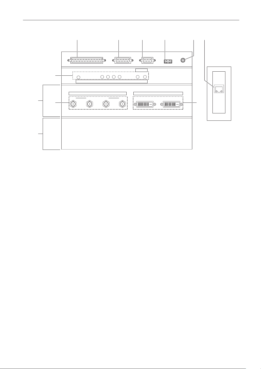
1-3-4. Connection terminals
1. External control terminal (GP I/O) (D-Sub 37P)
The terminal for externally controlling the projector or connecting a 3D image system to the projector. (See page 61)
2. 3D terminal (3D) (D-Sub 15P)
The terminal for connecting a 3D image system to the projector. (See page 66)
3. PC control terminal (RS-232C) (D-Sub 9P)
The terminal for service personnel to set data for the projector or for operating the projector from a PC via an RS-232C.
Connect the projector and the PC with a commercially available RS-232C straight cable.
4. USB port (USB) (type A)
The port for the projector maintenance.
5. Remote control device terminal (REMOTE) (Stereo mini)
The terminal for controlling the projector from a remote control device.
6. Ethernet port (LAN) (RJ-45)
The port for interfacing with an image signal server or controlling the projector from a PC via a network. Connect the projector
and the PC with a commercially available Ethernet cable (10/100/1000Base-T).
7. Device management indicator
The indicator for displaying the projector status. Used by service personnel during maintenance.
8. HDSDI input terminal (SDI-A/SDI-B/SDI-C/SDI-D) (BNC)
The terminal for connecting an image signal server or video imaging device. Use a 75Ω coaxial cable.
Use a combination of SDI-A and SDI-B, or SDI-C and SDI-D for a dual-link connection.
9. DVI-D input terminal (DVI-A/DVI-B) (DVI-D 24P)
The terminal for connecting a DVI-D output terminal of a PC. Use a commercially available DVI-D signal cable (singlelink).
10
. Slot B
The slot for a signal input board (NC-80LB01) or media block.
A signal input board is installed at the time of factory shipping. Contact your dealer/distributor for an installation or uninstallation
of a signal input board or media block.
11
. Slot A
The slot for a media block or internal multi-media switcher (MM3000B).
The slot is empty at the time of factory shipping. Contact your dealer/distributor for an installation of a media block or
internal multi-media switcher.
14
Page 15
1. What’s in the Box? and the Names of the Projector Parts
1
2
3
4
5
LAMP MENU ENTER
DOUSER
KEY
LOCK
EXIT
IMB
6
7
8
1 2
10 11 12 1413
3 5 6
7
8
9
4
Lit white
Lit green
Off
A title is assigned to the button
The title is being selected
No title is assigned to the button
NOTE
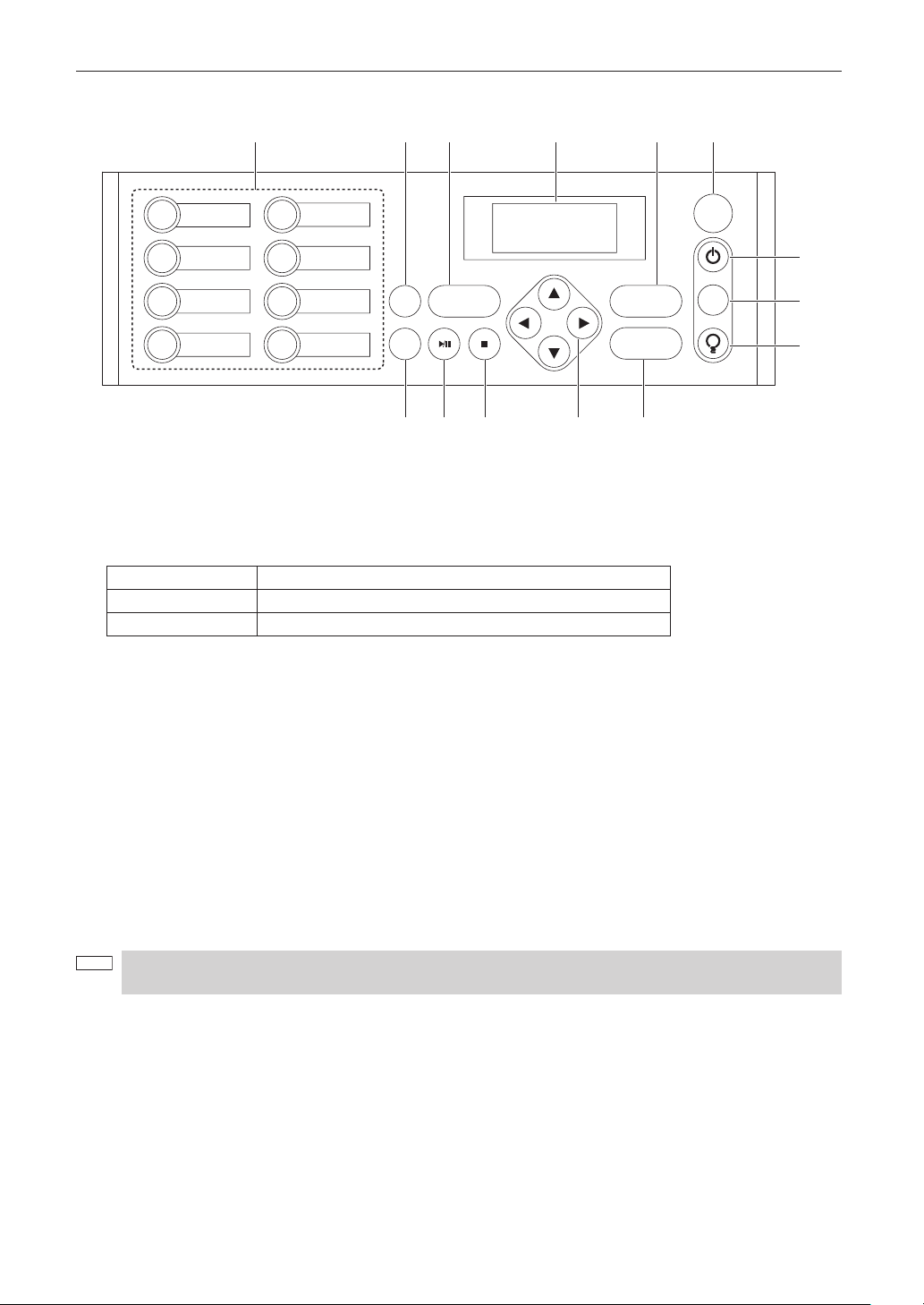
1-3-5. Control panel
1. Button <1> to <8>
Press the button <1> to <8> to select a title (input signal) assigned to each button.
Up to 100 titles (input signals) can be registered to this projector, and any 8 titles from them can be assigned to the button
<1> to <8>.
Indicators on the left of each button show their assigned title or selection status.
2. LAMP button
Press this button to display the lamp adjustment menu. (See page 27)
3. MENU button
Press this button to display the menu for various settings and adjustments. (See page 36)
4. LCD screen
The LCD screen displays menus and setting values for the projector operations.
5. ENTER button
Press this button to select the menu item.
6. KEY LOCK button
Press this button to lock (KEY LOCK) the buttons on the control panel. Buttons on the control panel do not function while
KEY LOCK is on.
Pressing the KEY LOCK button for one second or longer while KEY LOCK is off locks the buttons.
Pressing the KEY LOCK button for one second or longer while KEY LOCK is on unlocks the buttons. (See page 28)
KEY LOCK becomes automatically on if no control panel operation takes place in the standby state for 30 seconds
by default. (See page 28)
15
Page 16

1. What’s in the Box? and the Names of the Projector Parts
Lit green
Blinking green
Lit white
Blinking white
Power is on
The projector is starting up.
Power is off (in the standby state)
The cooling fan(s) is running immediately after a power-off.
7. POWER button
Press this button for more than three seconds to turn on or off (standby) the projector.
In order to start up the projector, turn on the main power switch for the lamp and then the main power switch for the projector
to set the projector in the standby state. (See page 21)
8. DOUSER button
Press this button to open and close the douser.
9. LAMP ON/OFF button
Press this button for five seconds or longer to turn on or off the lamp while the projector is on. (See page 29)
10
. IMB button
This button is operable when the media block is installed in the projector.
Press this button to display the operation menu of the media block.
11
. Play/pause button
This button is operable when the media block is installed in the projector.
Press this button to play or pause the image contents.
12
. Stop button
This button is operable when the media block is installed in the projector.
Press this button to stop playing the image contents.
13
. /// (UP/DOWN/LEFT/RIGHT) buttons
Press these buttons to select a menu item while a menu is displayed.
14
. EXIT button
Press this button to return to the previous menu item.
16
Page 17

2.
Installation and Connection
2-1. Steps for setting up and connecting
Use the following steps for setting up your projector:
• Step 1
Setup the screen and projector. (Contact your dealer to carry out the setup.)
• Step 2
Connect cables to the image input terminals. (See page 18)
Connect cables to the various control terminals. (See page 19)
17
Page 18
2. Installation and Connection
75Ω coaxial cable
Cinema server
HDSDI VTR
PC
DVI-D signal cable
A B
SDI DVI
C D A B
NC-80LB01
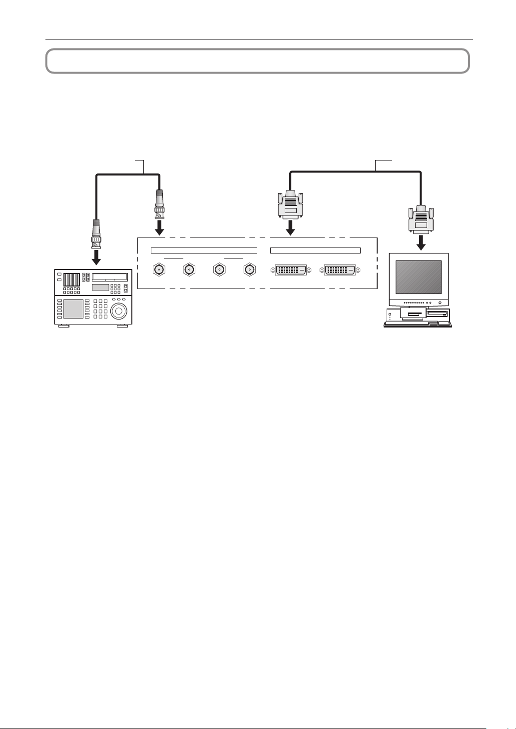
2-2. Connecting the image input terminals
The projector has two image input terminals (HDSDI input terminal and DVI-D input terminal).
• HDSDI A/B/C/D input terminal -----------------------(SDI-A/SDI-B/SDI-C/SDI-D)
• DVI-D A/B input terminal (DVI A/DVI B) -------------
Inputs serial digital images from a cinema server or an image device such
as HDSDI VTR.
Inputs digital RGB signals from a PC.
18
Page 19
2. Installation and Connection
GP I/O 3D RS-232
USB
REMOTE
LAN
PC
RS-232C
Ethernet cable
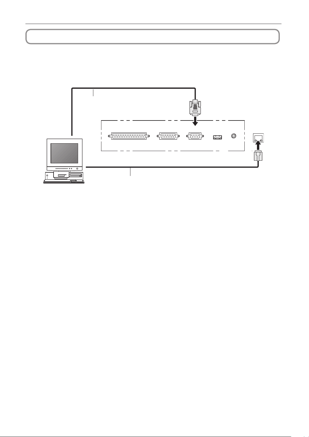
2-3. Connecting the various control terminal
For control, your projector comes with such ports as the PC control terminal and the Ethernet port (RJ-45).
• PC control terminal (RS-232) ---------------
• Ethernet port (LAN) ---------------------------
Use this terminal when controlling the projector in serial connection from a PC.
Use this port when controlling the projector in LAN connection from a PC.
19
Page 20

3.
Projection of Images (Basic Operation)
3-1. Steps of projecting images
• Step 1
Turn on the power to the projector. (See page 21)
• Step 2
Select the title of input signal. (See page 23)
• Step 3
Adjust the position and size of the projected screen. (See page 24)
• Step 4
Turn off the power to the projector. (See page 30)
20
Page 21
3. Projection of Images (Basic Operation)
NOTE
1
2
ON
3
1
2
3
4
5
L
A
M
P
M
E
N
U
E
N
T
E
R
D
O
U
S
E
R
K
E
Y
L
O
C
K
E
X
I
T
I
M
B
6
7
8
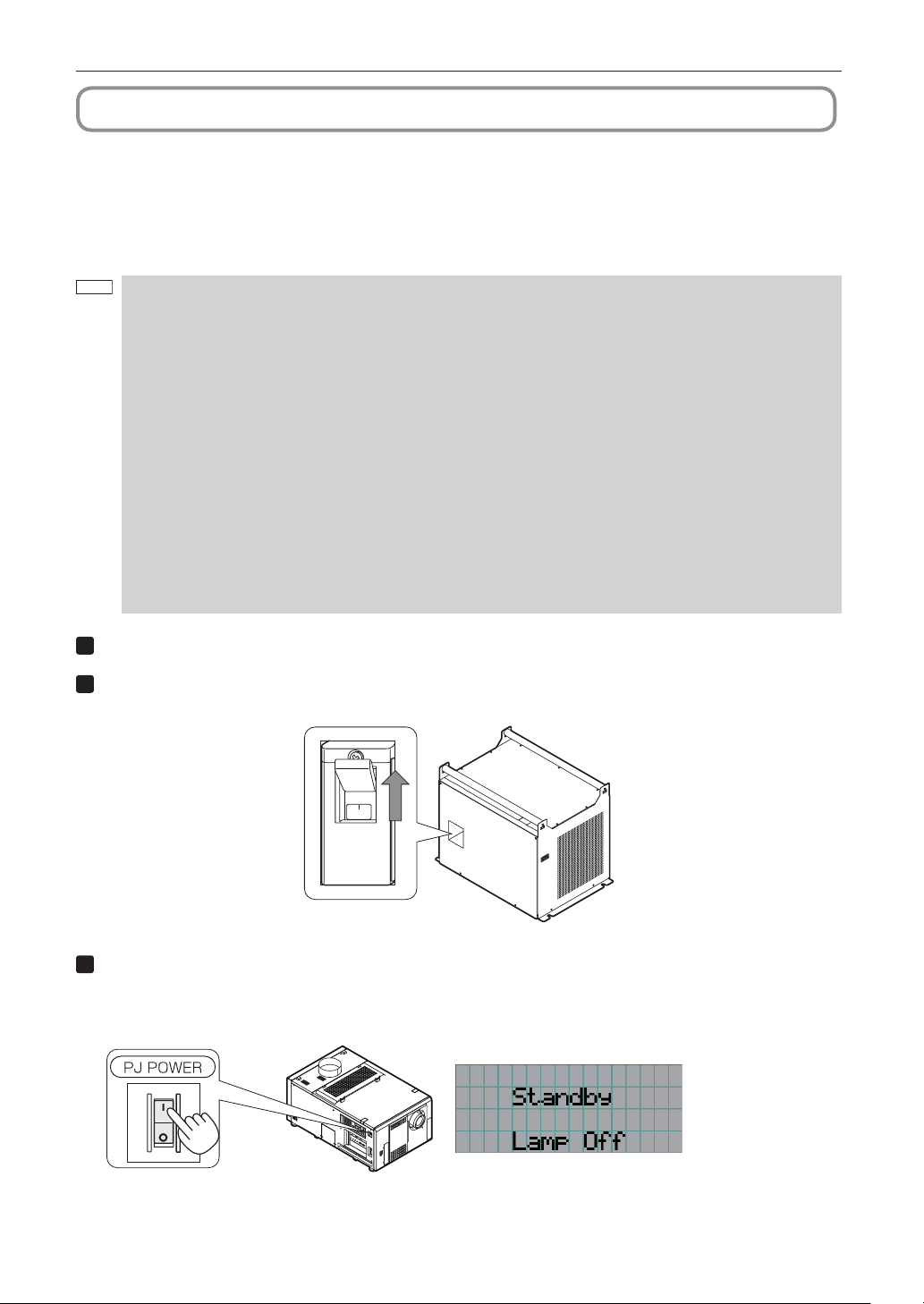
3-2. Turning your projector on
The power to this projector is separated to the power to the projector head and power to the lamp. To project an image, it is
necessary for both power supplies to be on.
Preparation: Supply AC power to the projector head and to the lamp power supply.
Please contact your dealer/distributor to connect the power cable.
• Turn off the main power switch to the projector head and the lamp power supply when supplying or cutting AC
power to the projector and the lamp power supply.
Supplying or shutting down the AC power while the main power switch is on will damage the projector.
• Turning on and off the projector involves a two-step operation; the “main power switch” and the “POWER
button”.
• Turning power on (See this page)
[1] Turn on the “main power switch” of the projector and the lamp power supply.
Your projector is set in a standby state.
[2] If KEY LOCK is on, press the KEY LOCK button for one second or longer.
KEY LOCK is off and buttons on the control panel become operable.
[3] Press the POWER button three seconds or longer.
Your projector is turn on.
• Turning power off (See page 30)
[1] Press the POWER button three seconds or longer.
Your projector is set in a standby state.
[2] When the fan has stopped, turn off the “main power switch” of the projector and the lamp power supply.
Your projector is turned off.
Remove the lens cap.
Turn the main power switch on the lamp power supply to on.
The lamp power fan will begin rotating.
Turn on the main power switch on the side of the projector.
A buzzer will ring on the projector. The POWER button will blink green and the Rear STATUS indicator will light orange
(standby state). KEY LOCK becomes automatically on if no control panel operation takes place in the standby state
for 30 seconds by default. Buttons on the control panel do not function while KEY LOCK is on. (See page 28)
21
Page 22

3. Projection of Images (Basic Operation)
4
LAMP MENU ENTER
DOUSER
KEY
LOCK
EXIT
IMB
5
POWER button
DOUSER button
LAMP ON/OFF button
Button <1> to <8>
Lit green
Lit green (douser is off)
Blinking white (lamp is off)
The button which was last selected is lit green
LAMP MENU ENTER
DOUSER
KEY
LOCK
EXIT
IMB
6
LAMP MENU ENTER
DOUSER
KEY
LOCK
EXIT
IMB
NOTE
If KEY LOCK is on, press the KEY LOCK button for one second or longer.
KEY LOCK becomes off. The color of the KEY LOCK button changes from orange to white, and buttons on the control
panel become operable. (See page 28)
Press the POWER button on the control panel of your projector three seconds or longer.
Your projector is turn on, and the screen glows light about 30 seconds later. The status of the POWER button, DOUSER
button, and LAMP ON/OFF button changes as follows.
Press the LAMP ON/OFF button on the control panel for five seconds or longer.
The lamp is turned on and the screen glows light about 15 seconds later. The LAMP ON/OFF button lights green.
The douser is closed until the screen glows light (the DOUSER button blinks white). When the douser is open, the
DOUSER button lights green.
22
• While your projector is on, be sure to have the lens cap removed from the lens.
Otherwise, the lens cap may get deformed due to a heat buildup.
• In the following instances, the power to your projector cannot be turned on even if you press the POWER
button.
- When the inside temperature is abnormally high. The protective function prevents power from turning on.
Wait some time (until the projector inside cools down) and then turn on the power.
- When the Rear STATUS indicator is blinking in red without the lamp lighting up after power-on. Your
projector may be in trouble. Check the error display on the LCD screen and contact your dealer/distributor
for instructions.
• Note that the image may sometimes flicker until the lamp has stabilized (5 to 10 minutes) after power-on. This
is due to the characteristics of the lamp and is not trouble of your projector.
Page 23

3. Projection of Images (Basic Operation)
1
2
3
4
5
6
3-3. Selecting the title of input signal
This projector allows you to select pre-registered signals using the signal selection buttons on the control panel (up to 8
signals). Request your dealer/distributor for details on registering and changing titles. This section explains the steps for
selecting registered signals.
Turn on the power to the image devices connected to the projector.
Press the MENU button.
Press the LEFT/RIGHT button to display “Title Select” on the LCD screen.
At each press of the LEFT/RIGHT buttons, the display will cycle as “Title Select” ←→ “Configuration” ←→ “(Title
Setup)” ←→ “Information.”
Press the DOWN button.
The title of the input signal is displayed.
• When you have made a wrong selection, press the UP button. A return will be made to the previous menu.
Press the LEFT/RIGHT buttons to display “Title of Signal to be Projected” on the LCD screen.
Press the ENTER button.
The title of the signal to be projected is selected.
• The (*) mark on the LCD indicates that this is the currently selected item.
23
Page 24

3. Projection of Images (Basic Operation)
1
1
2
3
4
5
L
A
M
P
M
E
N
U
E
N
T
E
R
D
O
U
S
E
R
K
E
Y
L
O
C
K
E
X
I
T
I
MB
6
7
8
2
3
4
5
6
3-4.
Adjusting the position and the size of projected screen
3-4-1. Displaying the test pattern
Press the MENU button, or select a test pattern from signal selection buttons (button <1> to <8>).
If you register the test patterns to the signal selection buttons (<1> to <8> buttons), select the test pattern according
to “3-3. Selecting the title of input signal (See page 23)”.
Press the LEFT/RIGHT button to display “Title Select” on the LCD screen.
Press the DOWN button.
The title of the input signal is displayed.
Press the LEFT/RIGHT button to display “TEST Pattern” on the LCD screen.
Press the DOWN button.
The LCD screen enters the mode where you can select a test pattern.
Press the LEFT/RIGHT button.
This switches the test pattern name displayed on the LCD screen.
24
Page 25

3. Projection of Images (Basic Operation)
7
1
2
3
4
5
6
1
2
3
4
5
L
A
M
P
M
E
N
U
E
N
T
E
R
D
O
U
S
E
R
K
E
Y
L
O
C
K
E
X
I
T
I
M
B
6
7
8
7
Display on the LCD the name of the test pattern to be projected, then press the ENTER
button.
The test pattern is displayed.
• To cancel the test pattern display, reselect the signal to be project.
3-4-2. Adjusting the position of the projected screen (Lens shift)
Press the MENU button.
Press the LEFT/RIGHT button to display “Configuration” on the LCD screen.
Press the DOWN button.
Press the LEFT/RIGHT button to display “Lens Control” on the LCD screen.
Press the DOWN button.
The screen (“Lens Position”) to adjust the position of the projected screen is displayed.
Press the UP/DOWN/LEFT/RIGHT button.
The position of the projected screen moves in the selected direction.
Press the EXIT button when adjustment is complete.
The display will return to a menu one level above (where “Lens Control” is displayed).
25
Page 26

3. Projection of Images (Basic Operation)
1
2
3
4
5
6
ENTER button
7
1
2
3
4
5
L
A
M
P
M
E
N
U
E
N
T
E
R
D
O
U
S
E
R
K
E
Y
L
O
C
K
E
X
I
T
I
M
B
6
7
8
1
2
3
4
5
L
A
M
P
M
E
N
U
E
N
T
E
R
D
O
U
S
E
R
K
E
Y
L
O
C
K
E
X
I
T
I
M
B
6
7
8
8
3-4-3. Fine adjustment of the size (zoom) and focus of the projected screen
Press the MENU button.
Press the LEFT/RIGHT button to display “Configuration” on the LCD screen.
Press the DOWN button.
Press the LEFT/RIGHT button to display “Lens Control” on the LCD screen.
Press the DOWN button.
The screen (“Lens Position”) to adjust the position of the projected screen is displayed.
Press the ENTER button.
The screen to adjust the size and focus of the projected screen is displayed.
Press the ENTER button to switch the display between “Lens Position” and “Focus Zoom” adjustments.
Adjust the size and focus of the projected screen.
Press the UP/DOWN button to adjust the focus.
Press the LEFT/RIGHT button for fine adjustment of the size.
Focus
(UP/DOWN button)
Zoom
(LEFT/RIGHT button)
Press the EXIT button when adjustment is complete.
The display will return to a menu one level above (where “Lens Control” is displayed).
26
Page 27

3. Projection of Images (Basic Operation)
1
LAMP MENU ENTER
DOUSER
KEY
LOCK
EXIT
IMB
2
3
4
1
2
3
4
5
L
A
M
P
M
E
N
U
E
N
T
E
R
D
O
U
S
E
R
K
E
Y
L
O
C
K
E
X
I
T
I
M
B
6
7
8
3-4-4. Adjusting the brightness of the projected screen (Lamp output)
Press the LAMP button.
“Lamp Setup” is displayed.
Press the DOWN button.
The screen to adjust the lamp output is displayed.
Press the LEFT/RIGHT button to adjust the lamp output.
Press the ENTER button.
The specified adjustment value is applied.
27
Page 28

3. Projection of Images (Basic Operation)
NOTE
1
LAMP MENU ENTER
DOUSER
KEY
LOCK
EXIT
IMB
1
3-5. Preventing misoperations
Buttons on the control panel can be locked (KEY LOCK) to prevent misoperations. Buttons on the control panel do not function
while KEY LOCK is on. KEY LOCK must be off to operate these buttons.
• KEY LOCK is automatically turned on in the following cases.
- When the projector has entered the standby state by turning on the main power switch of the projector and
the lamp power supply while the AC power is supplied.
- When the projector has entered the standby state after turning off the power using the POWER button.
• The timing where KEY LOCK is turned on while the projector is in standby state depends on the “Auto Key
Lock” setting in the adjustment menu.
- When Auto Key Lock is enabled, KEY LOCK becomes automatically on if no control panel operation takes
place in the standby state for 30 seconds. KEY LOCK becomes automatically on again even after KEY
LOCK is turned off if no control panel operation takes place for 30 seconds.
- When Auto Key Lock is disabled, KEY LOCK becomes automatically on when the projector enters the
standby state; however, it stays off after KEY LOCK is turned off.
3-5-1. KEY LOCK setting
Press the KEY LOCK button on the control panel for one second or longer.
KEY LOCK becomes on. The KEY LOCK button lights orange.
3-5-2. Turning KEY LOCK off
Press the KEY LOCK button for one second or longer while KEY LOCK is on.
KEY LOCK becomes off. The KEY LOCK button lights white.
28
Page 29

3. Projection of Images (Basic Operation)
1
LAMP MENU ENTER
DOUSER
KEY
LOCK
EXIT
IMB
1
3-6.
Turning on/off the lamp with the projector turned on
3-6-1. Turning off the lamp
Press the LAMP ON/OFF button on the control panel for five seconds or longer.
3-6-2. Turning on the lamp
Press the LAMP ON/OFF button on the control panel for five seconds or longer.
29
Page 30

3. Projection of Images (Basic Operation)
1
LAMP MENU ENTER
DOUSER
KEY
LOCK
EXIT
IMB
2
1
2
3
4
5
L
A
M
P
M
E
N
U
E
N
T
E
R
D
O
U
S
E
R
K
E
Y
L
O
C
K
E
X
I
T
I
M
B
6
7
8
3
OFF
4
NOTE
3-7. Turning your projector off
Press the POWER button on the projector control panel for three seconds or longer.
The lamp is turned off, the POWER button blinks white, and the Rear STATUS indicator blinks orange (cooling state).
The fan will continue to rotate while cooling, and the amount of time remaining for cooling is displayed on the LCD
screen. The cooling-off time is 5 minutes.
When the cooling is finished, the POWER button lights white, and the Rear STATUS indicator lights orange (standby
state). KEY LOCK becomes automatically on if no control panel operation takes place in the standby state for 30
seconds by default. Buttons on the control panel do not function while KEY LOCK is on. (See page 28)
Wait till the projector enters standby state before turning off the main power switch of the projector.
The POWER button is turned off and the main power is turned off.
Turn the main power switch on the lamp power supply to off.
The fan will continue to rotate for a short amount of time (approximately 5 seconds) immediately after turning off the power.
Turn off the AC power to the projector head and to the lamp power.
• In the following instances, do not turn off the main power switch or disconnect the AC power. Doing so can
damage the projector.
- While projecting images
- While the fan is running after the power is turned off (The cooling-off time is 5 minutes)
30
Page 31

← Displays the main menu or submenus.
← Displays submenus or selection items.
← Displays settings and selection status.
← Displays settings, selected items and information on selected menus.
Indicates that there is a menu of a higher level.
Press the UP button to return to a menu one level above.
Indicates that there is a selected item or menu at the same level.
Press the LEFT/RIGHT button to display other selected items or menus.
Indicates that there is a menu of a lower level.
Press the DOWN button to display the menu one level below.
Indicates that there are setting items of a lower level.
Press the UP button to return to a menu one level above.
Press the DOWN button to display the setting item one level below.
4.
Using Menus
4-1. Basic operation with adjustment menus
To adjust the projector, display the menu on the LCD screen of the projector control panel.
4-1-1. Screen display
The menu display screen is composed of a menu display field (the upper two lines) and a setting item display field (the bottom
two lines).
The meanings of symbols in the menu display screen are outlined below.
31
Page 32

4. Using Menus
← Displays the hours of lamp bulb use.
← Displays the lamp output (%).
← Displays the selected title.
← Displays the selected port.
When not displaying menus, the following screen is normally displayed.
When in standby
When the projector is in a standby state (the main power switch in on), the following is displayed.
When power is turned on
When the power is turned on, the following is displayed.
When the power is turned off
The amount of time remaining for cooling is displayed as shown below, when the power to the projector head is turned off.
When a button is pressed while the key lock function is on
If a button on the control panel is pressed while the key lock function is on, the following is displayed and the button will not
function.
32
Page 33

4. Using Menus
1
2
3
4
5
4-1-2. Operating menus
Preparation: Turn your projector on. (See page 21)
Press the MENU button on the control panel of your projector.
The menu is displayed in the LCD screen.
Press the LEFT/RIGHT buttons to display “Information.”
At each press of the LEFT/RIGHT buttons, the display will cycle as “Title Select” ←→ “Configuration” ←→ “(Title
Setup)” ←→ “Information.”
Press the DOWN button.
The submenu “Lamp” of “Information” is displayed.
The menu item can be selected by pressing the ENTER button instead of the DOWN button
To return to the previous state, press the UP button, or the EXIT button.
Press the LEFT/RIGHT button to select the submenu “Version.”
At each press of the LEFT/RIGHT button, the display will cycle as “Lamp” ←→ “Preset Button” ←→ “Usage” ←→
“Error Code” ←→ “Version” ←→ “IP Address” ←→ “Setup Date” ←→ “Option Status.”
Press the DOWN button.
The submenu “System” another rank lower than “Version” is displayed.
33
Page 34

4. Using Menus
6
7
8
Press the DOWN button.
The submenu “BIOS” another rank lower than “System” is displayed.
Press the LEFT/RIGHT button to select the submenu “Data.”
At each press of the LEFT/RIGHT button, the display will cycle as “BIOS” ←→ “Firmware” ←→ “Data” ←→ “Serial
No.” ←→ “Model,” and each version information is displayed.
Press the UP button several times.
At each press of the UP button, the display will return to a menu one level above.
34
Page 35

4-1-3. How to enter alphanumeric characters
1
2
3
4
5
LAMP MENU ENTER
DOUSER
KEY
LOCK
EXIT
IMB
6
7
8
Enter characters
Delete entered characters
Move right and left
Button
1
2
3
4
5
6
7
8
LAMP
IMB
Entered character
A → B → C → 1 → a → b → c → ! →
D → E → F → 2 → d → e → f → " →
G → H → I → 3 → g → h → i → # →
J → K → L → 4 → j → k → l → $ →
M → N → O → 5 → m → n → o → % →
P → Q → R → 6 → p → q → r → & →
S → T → U → 7 → s → t → u → ’ →
V → W → X → 8 → v → w → x → ( →
Y → Z → / → 9 → y → z → ? → ) →
* → , → . → 0 → ; → : → + → - →
NOTE
Alphanumeric characters are entered for items, such as the title of input signal.
Characters can be entered by pressing numeric buttons on the control panel on this projector.
Characters can be entered by pressing each button as shown in the following table.
• To delete a character during entry, press the DOWN button.
[Example of Entry]
To enter “XGA” for example, use the following procedure:
(1) Press the “8” button three times.
V
→ W → X
(2) Press the RIGHT button.
(3) Press the “3” button.
XG
(4) Press the RIGHT button.
(5) Press the “1” button.
XGA
4. Using Menus
To input characters using the remote control, only numbers can be entered with [password] and the security
[keyword].
35
Page 36

4. Using Menus
4-2. Table of adjustment menus
Menus in parentheses are menus for our service personnel. Normally, these menus cannot be used.
Main menu Submenu Description
Title Select “Title Memory Name” Selects the title of the signal to be projected. 37
Configuration Lamp Setup Adjust Adjusts lamp brightness. 38
(Title Setup) Preset Button Preset Button 1-8 Sets the title to be assigned to the preset buttons (<1> to <8> buttons). 39
Information Lamp Output Displays the lamp output setting. 39
TEST Pattern Selects the test pattern to be projected. 37
Lens Control Lens Position Adjusts the position of the projected screen. 38
(Setup) Douser Mode Selects whether to use the douser (screen mute) when switching
(Installation) (Option Slot) Configures the device installed in slot A and slot B (only when the
(Memory) Lamp Saves the current lamp setting. -
Preset Button Preset Button 1-8 Displays the titles which are assigned to the preset buttons (<1> to
Usage Displays the usage time of the projector, lamp bulb, lamp house, bulb
Error Code Displays the currently occurring error. 40
Version System Displays the model and version (BIOS, firmware, data, and serial No.)
IP Address System Displays the IP address of the projector. 42
Setup Date Displays the date when the projector was set up (starting date of the
Option Status Displays the link status of the device mounted in slot A and slot B, and
Feedback Sets the lamp brightness constant mode that uses a brightness sensor. 38
Focus Zoom Fine tunes the size and focus of the projected screen. 38
PowerOn Douser Sets the douser status (ON/OFF) when the projector is turned on. Turret Controls the turret mounted with an anamorphic lens (or wide converter
Panel Key Lock Locks the buttons on the projector’s control panel so that they cannot
Auto Key Lock Enables or disables Auto Key Lock. 3D Connector Sets the signal input terminal for a 3D image system (3D terminal or
FactoryDefault Returns the settings to their default values. Selects between preset
Image Orient Selects the projection method (front/rear). Lens Center Moves the lens shift position to the center. MMS Select Selects the multi-media switcher (MMS) to connect. Baudrate Sets the PC control connector (RS-232C) data transmission speed
Date/Time Sets the date and time on the projector. (New Bulb) Resets the lamp bulb usage time and selects or edits new entries (only
(Bulb Warning) Sets the lamp bulb warning time (only when the projector is in standby
(New Lamp house) Resets the lamp house usage time, and makes settings or selects
Bulb Alignment Sets the lamp bulb alignment. Usage Reset Initializes the usage time of the fan and air filter. NewRouterSetup Sets the router with the default settings when the router built-in the
Lens Saves the current lens setting. -
Bulb Type [A] Displays the registered name and the maximum/minimum current
Bulb Type [W] Displays the registered name and the lamp rated output (kW) of the
Bulb Type [H]
SIB Displays the version of the signal input board (NC-80LB01). 41
IMB Displays the version of the media block (IMB). 41
MMS(Built-in) Displays the version of the built-in multi-media switcher (MMS). (BIOS,
signals.
lens).
be operated.
GPI/O terminal).
buttons and titles only, LAN settings only and all settings.
projector is in standby mode).
(bps).
when the projector is in standby mode).
mode).
modes (only when the projector is in standby mode).
projector has been replaced.
setting of the currently used lamp bulb.
currently used lamp bulb.
Displays the registered name and the lamp bulb warning time (Bulb
Warning Time) setting of the currently used lamp bulb.
<8> buttons).
warning, fan, and air filter.
of the projector.
Firmware, Data, FPGA, and Serial No.)
warranty period).
the projector.
Reference
page
-
-
-
-
-
-
-
-
-
-
-
39
39
39
40
40
41
41
42
42
36
Page 37

4. Using Menus
← Displays the currently selected item with asterisk (*).
← Selects the title to be projected.
OFF, Alignment, Convergence, H-Ramp, RGB-Black, RGB-Blue,
RGB-Green, RGB-Red, RGB-White, Y-Color Bars, YCbCr-Blue,
YCbCr-Green, YCbCr-Red, YCbCr-White, RGB-CROSS, RGB-50%-White
← Displays the currently selected item with asterisk (*).
← Selects the test pattern to be projected.
4-3. Title Select
4-3-1. Title select (Title Memory)
Selects the title of the signal to be projected.
You can register up to 100 titles. You can also assign registered titles to the preset buttons (<1> to <8> buttons) on the projector’s
control panel and call them up directly using those buttons.
Request your dealer/distributor for details on registering and changing titles.
4-3-2. Test Pattern
Selects the test pattern to be projected.
37
Page 38

4. Using Menus
← Displays the lamp output (%) with regard to the setting.
← Adjusts the lamp brightness.
Disable
Enable
Disables the lamp brightness constant mode.
Enables the lamp brightness constant mode.
← Displays the currently selected item with asterisk (*).
← Displays the setting.
4-4. Configuration
Please request your dealer/distributor to perform the settings.
4-4-1. Lamp Setup
Adjust
Adjusts the lamp output (brightness). Control the output at 10 W increments.
Feedback
Sets the lamp brightness constant mode that uses a brightness sensor.
4-4-2. Lens Control
Adjust the position, size, and focus of the projected screen.
Press the ENTER button to switch the display between “Lens Position” and “Focus Zoom” adjustments. Press the EXIT button
to return to a menu one level above.
Lens Position
Adjusts the position of the projected screen.
The projected screen moves in the selected direction as you press the UP/DOWN/LEFT/RIGHT button.
Focus Zoom
Fine tunes the size (Zoom) and focus (Focus) of the projected screen.
Press the UP/DOWN button to adjust the focus.
Press the LEFT/RIGHT button to adjust the size of the projected screen.
38
Page 39

4. Using Menus
← Displays the set current (A).
← Displays the power consumption (kW).
← Displays Bulb Entry registered name.
← Displays Bulb Entry maximum/minimum currents (A).
← Displays Bulb Entry registered name.
← Displays Bulb Entry lamp rated output (kW).
← Displays Bulb Entry registered name.
← Displays Bulb Warning Time setting (H).
4-5. Title Setup
Sets the title to be assigned to the preset buttons (<1> to <8> buttons).
Request your dealer/distributor to perform the settings.
4-6. Information
Displays the hours of lamp bulb use, the version information and error codes.
4-6-1. Lamp
Displays information relating to the lamp. (Such as lamp output and the information of lamp bulb.)
Output
Displays the lamp brightness (output) setting.
Bulb Type [A]
Displays the registered name and the maximum/minimum current setting of the currently used lamp bulb.
Bulb Type [W]
Displays the registered name and the lamp rated output (kW) of the currently used lamp bulb.
Bulb Type [H]
Displays the registered name and the lamp bulb warning time (Bulb Warning Time) and setting of the currently used lamp
bulb.
39
Page 40

4. Using Menus
← Selects the preset button number whose contents you want to display.
← Displays the assigned title numbers.
← Displays the registered names of the assigned titles.
Projector
Bulb
Lamp house
Bulb Warning
AC On Fan
Power On Fan
Lamp Fan
Filter
Displays the hours of projector head use.
Displays the hours of use of the current lamp bulb (Lamp utilization time).
Displays the hours of use of the current lamp house.
Displays the currently enabled warning time. The following is displayed depending on
the item set by the Bulb Warning setting.
• When Use Bulb Entry is enabled: Displays the Bulb Entry value.
• When in Manual setting: Displays the value set using Manual.
Displays the usage time (on the AC power supply) of the projector cooling fan.
Displays the usage time (on the projector's power supply) of the projector cooling fan.
Displays the usage time of the lamp cooling fan.
Displays the usage time of the air filters (for the projector head and for the lamp).
← Selects the item to display.
← Displays the hours of use (H).
← Displays the code of the error currently occurring.
← Displays the name of the error currently occurring.
4-6-2. Preset Button
Sets the title to be assigned to the preset buttons (<1> to <8> buttons) on the projector’s control panel.
4-6-3. Usage
Displays the hours of projector head, lamp, and lamp house usage, and warning display time of the lamp bulb.
4-6-4. Error Code
Displays the error code when an error occurs. See the “Error Code List” in the Appendix for details on error codes.
40
When multiple errors occur, you can display them by pressing the LEFT/RIGHT buttons.
Page 41

4-6-5. Version
BIOS
Firmware
Data
Serial No.
Model
Displays the BIOS version of the projector head.
Displays the firmware version of the projector head.
Displays the data version of the projector head.
Displays the serial number of the projector head.
Displays the model name of the projector head.
← Selects the item to display.
← Displays the version information.
← Displays the version information.
← Displays the version information.
BIOS
Firmware
Data
FPGA
Cfg FPGA
Serial No.
Displays the BIOS version of the built-in multi-media switcher (MM3000B).
Displays the firmware version of the built-in multi-media switcher (MM3000B).
Displays the data version of the built-in multi-media switcher (MM3000B).
Displays the FPGA version of the built-in multi-media switcher (MM3000B).
Displays the configuration FPGA version of the built-in multi media switcher (MM3000B).
Displays the serial number of the built-in multi-media switcher (MM3000B).
← Selects the item to display.
← Displays the version information.
Displays the versions of the projector head, and the multi-media switcher (MMS) (optional).
System
Displays the version information of the projector head.
SIB
Displays version information of the signal input board (NC-80LB01).
4. Using Menus
IMB
Displays the version information of the media block.
MMS (Built-in)
Displays the version of the built-in multi-media switcher (MM3000B) connected to the projector head.
41
Page 42

4. Using Menus
System Displays the IP address set for the projector head (System).
← Displays the IP address.
← Displays the date when the projector was set up (starting date of the warranty
period).
B
A
Displays the link status of the device in slot B.
•
SIB: Signal input board
•
IMB: Media block
•
No Board: No device mounted
Displays the link status of the device in slot A.
•
MMS: Multi-media switcher
•
IMB: Media block
•
No Board: No device mounted
← Displays the link status of the device in slot B.
← Displays the link status of the device in slot A.
4-6-6. IP Address
Displays the IP address set in the projector head.
4-6-7. Setup Date
Displays the date when the projector was set up (starting date of the warranty period).
4-6-8. Option Status
Displays the link status of the device mounted in slot A and slot B (signal input board, multi-media switcher, or media block)
on the projector.
Normally the device name mounted in slot A and slot B are displayed. The device name is displayed in ( ) when the projector
is in standby or when connection to the device cannot be confirmed.
42
Page 43

NOTE
NOTE
5.
Maintenance of Your Projector
Please request your dealer to perform lamp replacement and cleaning of the projector inside.
5-1. Cleaning the Cabinet
Be sure to always check that the AC power supply of the projector head is disconnected before carrying out maintenance of
your projector.
• Wipe with a dry, soft cloth without nap.
When the cabinet is excessively dirty, wipe with cloth well wrung after being dampened with a neutral detergent diluted with
water and then finish up with a dry cloth.
When you use a chemical dust cloth, follow the instructions in the manual attached to it.
• Do not use a solvent, such as thinner or benzene. The coating may deteriorate or peel off.
• When removing dust on the ventilation opening, suck it off using an adapter with a brush on a vacuum cleaner. Never allow
the cleaner without an adapter to come into direct contact or use a nozzles adapter in cleaning.
• Clean the ventilation opening at regular intervals. Dust, if allowed to accumulate there, may cause heating inside, which
leads to functional trouble. The interval, which can vary with the location of your projector, is about 100 hours.
• Do not damage the cabinet by scratching it or allowing hard objects to hit it. This can scratch the projector.
• Consult your dealer/distributor about cleaning the inside of the projector.
Do not allow insecticide or other volatile liquid to splash on the cabinet, lens or screen. Also, do not allow any rubber
or plastic object to remain in contact with the cabinet for a long time. The coating may deteriorate or peel off.
5-2. Cleaning the Lens
Clean the lens the same way as with camera lens (using a commercially available camera blower or cleaning paper for glasses).
Take care not to damage the lens when cleaning.
43
Page 44

5. Maintenance of Your Projector
NOTE
Air inlets for the projector
electric circuit (side)
Air inlet for the lamp
Air inlet for the projector
electric circuit (front)
Replacement frequencyModel numberAir inlet
Lamp air inlet NC-80AF01 When replacing the lamp
Projector air inlet NC-80AF02 Every 2,000 hours of usage or 6 months, whichever is earlier
5-3. Replacing the Air Filter
Air filters are attached over the air inlet of the projector to prevent dust. Replace air filters periodically to maintain the projector’s
performance.
WARNING:
• When replacing air filters, turn off the projector and shut down the AC power to the projector using a circuit breaker.
• Dust in air filters will hinder ventilation of the projector, lead to a rise of the internal temperature and may cause a fire or
malfunction.
Please purchase the replacement air filter at your dealer/distributor. Specify NC-80AF01 (for the air inlet of the
lamp) or NC-80AF02 (for the air inlet of the projector electric circuit) when you order.
44
Page 45

5. Maintenance of Your Projector
1
2
NOTE
3
Latch
5-3-1. Replacing air filters for the lamp air inlet
Prepare the optional NC-80AF01 to replace air filters for the lamp air inlet. The NC-80AF01 contains six replacement air filters.
Three air filters are required for the lamp air inlet.
Turn off the power to the projector.
Open the air inlet cover.
The air inlet cover is fastened by a leg on the top left corner of the cover when the project is facing towards you. Lift
the leg up to open the air inlet cover.
Take care not to damage the upper surface of the projector when opening the air inlet cover.
Remove the filter cover.
Push the latch until it clicks to unlock the filter cover.
45
Page 46

5. Maintenance of Your Projector
4
5
Latch
Replace with new air filters.
Look for an arrow indicating the installation direction on the side of the air filter. Place the filter so that the arrow is
pointing down at the projector.
Mount the filter cover.
Align two fasteners on the filter cover to holes on the projector, and push in until the latch clicks to mount the filter
cover.
46
Page 47

5. Maintenance of Your Projector
6
1
2
Latch
NOTE
Close the air inlet cover.
Fasten the air inlet cover by inserting the protrusion on the top left leg into the hole on the projector when the projector
is facing towards you.
This completes replacement of the air filters for the lamp air inlet.
5-3-2. Replacing air filters for the projector air inlet on the front
Prepare the optional NC-80AF02 to replace air filters for the projector air inlet on the front. The NC-80AF02 contains four
replacement air filters. Two air filters are required for the projector air inlet on the front.
Turn off the power to the projector.
Remove the air inlet cover.
Push the latch until it clicks to unlock the air inlet cover. The air inlet cover is attached to the projector by the bottom
edge.
Take care not to drop the cover when removing the air inlet cover.
47
Page 48

5. Maintenance of Your Projector
3
Latch
4
5
Latch
Remove the filter cover.
Push the latch until it clicks to unlock the filter cover.
Replace with new air filters.
Look for an arrow indicating the installation direction on the side of the air filter. Place the filter so that the arrow is
pointing down at the projector.
Mount the filter cover.
Align two fasteners on the filter cover to the holes on the projector, and push in until the latch clicks.
48
Page 49

5. Maintenance of Your Projector
6
Latch
1
2
Latch
Mount the air inlet cover.
Align the catches on the bottom of the air inlet cover with the protrusions on the projector, and push in until the latch
clicks to mount the air inlet cover.
This completes replacement of the air filters for the projector air inlet on the front.
5-3-3. Replacing air filters for the projector air inlets on the side
Prepare the optional NC-80AF02 to replace air filters for the projector air inlets on the side. The NC-80AF02 contains four
replacement air filters. Two air filters (one each for two air inlets) are required for the projector air inlets on the side.
Turn off the power to the projector.
Remove the filter cover.
Push the latch until it clicks to unlock the filter cover.
49
Page 50

5. Maintenance of Your Projector
3
AI
R
FL
OW
AIR
F
LOW
4
Latch
5
Replace with new air filters.
Look for an arrow indicating the installation direction on the side of the air filter. Place the filter so that the arrow is
pointing down at the projector.
Mount the filter cover.
Align two fasteners on the filter cover to the holes on the projector, and push in until the latch clicks.
Repeat Step 2 to 4 to replace one more air filter.
This completes replacement of the air filters for the projector air inlets on the side.
50
Page 51

6.
Appendix
6-1. Troubleshooting
Before asking for repair, please check your connection, settings and operation once again. If the trouble cannot be corrected,
please contact your dealer/distributor for instructions or repair.
6-1-1. Problems and where to check
Problem Check these items
The projector cannot be turned on.
The image cannot be projected. Check to see if the connected input has been selected.
The image is distorted. Check to see if the protractor is properly set up.
The image is blurred. Make certain that the lens is properly focused.
Video image is disturbed Check whether the signal cable connected to the projector is disconnected.
Check to see if AC power is supplied to the projector.
Make certain that the main power switch is ON.
Check to see whether the panel key lock function is activated. If so, the main unit’s control
buttons are locked and do not work.
Is the temperature inside the projector too high? When the inside temperature is too high, the
protective function does not allow your projector to be turned on. Wait some time and then turn it on.
Check to see if a cable is properly connected to the input terminal.
Check to see whether the douser is closed.
Check to see if the settings are all adjusted properly.
Check to see if the screen and a projector are installed at correct angles.
The projection distance may be larger than the focusing range.
See if the lens and other parts have condensation on them. If the projector is turned on in a
warm place after storage in a cold place, the lens and other optical components inside may
develop condensation. In such a case, please wait several minutes until the condensation
disappears.
51
Page 52

6. Appendix
Problem Check these items
The STATUS indicator blinks in red.
An error code is displayed. Please contact your dealer/distributor for instructions.
Your projector may have trouble. Please contact your dealer/distributor for instructions.
52
Page 53

6. Appendix
1
2
3
4
5
LAMP MENU ENTER
DOUSER
KEY
LOCK
EXIT
IMB
6
7
8
POWER button
KEY LOCK button
DOUSER button
LAMP ON/OFF button
Indicator condition
Steady light White
Orange
Projector condition
The key lock is off.
The key lock is on.
Note
-
-
Indicator condition
Off
Blinking light
Steady light
Projector condition
The project power supply is off.
The projector is starting up.
The projector is cooling down.
The projector is turned on.
The projector is in standby.
Note
-
Wait for a moment.
Wait for a moment.
-
-
Green
White
Green
White
Indicator condition
Blinking light White
Steady light Green
Projector condition
The douser is closed.
The douser is opened.
Note
-
-
Indicator condition
Blinking light White
Steady light Green
Projector condition
The lamp is off.
The lamp is on.
Note
-
-
6-2. Indicator display list
See the descriptions below when any of four buttons on the control panel or the Rear STATUS indicator on the rear of the
projector is lit or blinking. The projector also has a warning function that uses a buzzer.
6-2-1. KEY LOCK button
6-2-2. POWER button
6-2-3. DOUSER button
6-2-4. LAMP ON/OFF button
53
Page 54

6. Appendix
Indicator condition
Off
Blinking light
Steady light
Projector condition
Main power is off.
The projector is getting ready to turn on.
The douser is closed.
The lamp is off.
The projector is cooling down.
Safety problem, error
Error with possible image project under certain
conditions.
The projector is turned on.
The projector is in standby.
Error at a level with not affect on projection.
Note
-
Wait for a moment.
Wait for a moment.
An error message is displayed in
the LCD screen.
Check the content of the error.
-
-
An error message is displayed in
the LCD screen.
Check the content of the error.
Green
Orange
Red (With buzzer)
Red (Without buzzer)
Green
Orange
Red
6-2-5. Rear STATUS indicator
54
Page 55

6. Appendix
NOTE
6-3. Operation using an HTTP browser
6-3-1. Overview
The use of HTTP server functions will allow control of the projector from a web browser. Please be sure to use “ Microsoft Internet
Explorer 4.x” or a higher version for the web browser.
This device uses “JavaScript” and “Cookies” and the browser should be set to accept these functions. The setting method will vary
depending on the version of the browser. Please refer to the help files and the other information provided in your software.
The display’s or button’s response can be slowed down or operation may not be accepted depending on the
settings of your network.
Should this happen, consult your network administrator.
The projector may not respond if its buttons are repeatedly pressed in rapid intervals. Should this happen,
wait a moment and repeat. If you still cannot get any response, pull out and then reinsert the LAN card on the
projector.
Access is gained to the HTTP server functions by and specifying
http://<the projector’s IP address>/index.html
in the entry column of the URL.
6-3-2. Preparation before use
Make network connections and set up the projector and confirm that it is complete before engaging in browser operations.
Operations with a browser that uses a proxy server may not be possible depending on the type of proxy server and the setting
method. Although the type of proxy server will be a factor, it is possible that items that have actually been set will not be
displayed depending on the effectiveness of the cache, and the contents set from a browser not be reflected in operation. It
is recommended that a proxy server not be used unless it is unavoidable.
6-3-3. Handling of the address for operation via a browser
Regarding the actual address that is entered for the address or entered to the URL column when operation of the projector
is via a browser, the host name can be used as it is with the host name corresponding to the IP address of the projector has
been registered in the domain name server by a network administrator, or the host name corresponding to the IP address of
the projector has been set in the “HOSTS” file of the computer being used.
(Example 1) When the host name of the projector has been set to “pj.nec.co.jp”
http://pj.nec.co.jp/index.html is specified for the address or the entry column of the URL to access HTTP server
functions.
(Example 2) When the IP address of the projector is “192.168.10.10”
http://192.168.10.10/index.html is specified for the address or the entry column of the URL to access HTTP server
functions.
55
Page 56

6. Appendix
Power
Title List
Basic Control
Lens
Mute
Projector Status
Controls the power to your projector.
• On: Turns the power on.
• Off: Turns the power off.
Displays titles set in the projector (such as input port, screen type, and title).
Check, and the title will be changed.
Displays the basic control items.
Controls the lens operation.
: Shifts the projected screen upward.
: Shifts the projected screen downward.
: Shifts the projected screen leftward.
: Shifts the projected screen rightward.
: Stops the shifting.
Shifting can also be stopped by clicking the same button one more time.
: Zooms up the lens.
: Zooms down the lens.
: Stops the zooming.
Zooming the can also be stopped by clicking the same button one more time.
: Focuses up the lens.
: Focuses down the lens.
: Stops the focusing.
Focusing can also be stopped by clicking the same button one more time.
Click and the douser closes and the projected picture disappears. Click once again and the
picture will be projected again.
Displays the condition of the projector.
• Port: Displays the input port of the selected title.
• Lamp Usage: Displays the hours of lamp use.
• Lamp Power: Displays lamp output (%).
• Error Status: Displays the status of errors occurring within the projector.
• Refresh: Updates the display of the following conditions.
Shift
Zoom
Focus
Picture
6-3-4. Structure of the HTTP server
56
Page 57

6-4. Outline Drawing
700
146
600
1139
1124
503
359
6-4-1. Projector head (NC3200S)
6. Appendix
Units: mm
57
Page 58

6. Appendix
566
51 295
12
12
14
14
452
594
397
393
6-4-2. Lamp power supply (NC-32PS01)
Units: mm
58
Page 59

6. Appendix
6-5. Specifications
Model No. NC3200S
Projection method 3 chip DLP Cinema® method (1.25-inch DC2K chip)
Panel resolution 2048 x 1080
Lamp type 4.5/6.0/7.0 kW xenon lamp (Note 1)
Screen sizes 15 m to 30 m (Width) (Depends on setup conditions)
Contrast ratio 2200:1 or above
Lens adjustment function Motorized lens shift (ver tical/horizontal), motorized zoom, motorized focus, douser
Signal input ports (Note 2) Slot B Signal input board (NC-80LB01) mounted as standard
Slot A When shipped from factory: Empty (for mounting optional components)
External Control RS-232C D-sub 9 pin x 1
Power supply
voltage
Input current Projector head 7 A
Consumption Projector head 0.7 kW
Power Lamp power supply 9.7 kW
Cooling method Cooling fluid system, Cooling air system (includes dust filter)
Noise level Less than 66 dB
Installation Orientation:Desktop/front, Desktop/rear
Net weight Projector head 99 kg (Excluding lens)
Dimensions Projector head 700 mm (W) x 1124 mm (D) x 503 mm (H) (Does not include protruding
Environment Operating temperature: 10 to 35 ˚C
Regulations
GPIO port D-sub 37 pin x 1
Remote control input port stereo mini jack x 1
3D CTL D-sub 15 pin x 1
USB Type A x 1
Interlock port x 1
Ethernet port G-bit RJ-45 x 1
Anamorphic Lens Turret control port x 1
Projector head AC100 to 240 V, 50/60 Hz single phase
Lamp power supply AC200-230 V, 50/60 Hz Three-phase (Star connection)
Lamp power supply 28 A (200 to 230 V), 17 A (380 to 415 V)
Lamp power supply 52 kg
Lamp power supply 594 mm (W) x 397 mm (D) x 452 mm (H)
Operating humidity: 10 to 85% (non-condensing)
Storage temperature: -10 to 50 ˚C
Storage humidity: 10 to 85%
USA UL60950-1 FCC Class A
Canada CSA60950-1 ICES-003 Class A
Europe EN60950-1 EN55022 Class A
Oceania IEC60950-1 AS/NZS CISPR.22 Class A
Japan J60950 VCCI Class A
Asia IEC60950-1 CISPR. 22
(Note 1) Using any lamp other than NEC’s optional lamps will result in lower brightness compared to NEC optional lamps. If
brightness is important to you, it is recommended that you use NEC’s optional lamps.
NEC will post information on its homepage regarding installable lamps, other than NEC’s optional lamps. Note that
NEC does not guarantee performance and reliability when lamps other than NEC’s optional lamps are installed.
(Note 2) In addition to the input ports described above that are mounted when the device is shipped, Image Media Block and
Multi Media Switcher are available as separate optional products. A wider variety of input interfaces can be supported
by mounting these in slot A.
* Note that these specifications and design can change without prior notice.
SDI (4) BNC (SMPTE 292M, 372M)
RGB DIGITAL (2) DVI-D 24pin (TMDS specification)
AC380-415 V, 50/60 Hz Three-phase (Star connection) Switch type
portions Includes foot)
<Safety> <EMC>
EN55024
59
Page 60

6. Appendix
Pin
No.
1
2
3
4
5
6
7
8
9
RS-232C
Signal Name
CD
RXD
TXD
DTR
GND
DSR
RTS
CTS
RI
Functions as RS-232C
Carrier detection
Reception data
Transmission data
Data Terminal ready (Note 1)
Signal GND
Data set ready (Note 1)
Transmission request
Transmission available
Ring indicator
Projector Connector Operation
Not used (N.C.)
Data transmission to an external device
Data reception from an external device
Connection to 6 pins
Signal GND
Connection to 4 pins
SYSTEM (Note 2): Hi-Z (Not used)
CINEMA (Note 2): Hi-Z (Used)
SYSTEM (Note 2): Fixed at -6.5 V (Not used)
CINEMA (Note 2): ± 10.5 V (Used: Depends
on communication status)
Not used (N.C.)
Note 1: Do not use DTR and DSR signals when communicating.
Note 2: Connector operations vary according to the PC control signal switch
(CINEMA/SYSTEM). (When in SYSTEM, do not use RTS and CTS signals.)
12345
6789
6-6. Pin Assignment and Functions of Terminal
6-6-1. PC CONTROL connector (RS-232) (D-Sub 9 pin)
This is an RS-232C interface for controlling the projector head from a PC. The projector operates as a DCE (Data Communication
Equipment), so use a straight cable when connecting to a PC.
60
Page 61

6-6-2. External control connector (GP I/O) (D-Sub 37 pin)
19 18 17 16 15 14 13 12 1 1 10 9 8 7 6 5 4 3 2 1
37 3 6 35 3 4 33 3 2 31 3 0 29 2 8 27 2 6 25 2 4 23 2 2 21 2 0
Pin view of female connector
Pin No.
1
2
3
4
5
6
7
8
9
10
11
12
13
14
15
16
17
18
19
Signal Name
GPIN1+
(3D L/R Input Reference +)
GPIN2+
(3D L/R Display Reference +)
GPIN3+ (system reserved)
GPIN4+ (system reserved)
EXT_GPIN1+
(Control and Title Selection +)
EXT_GPIN2+
(Control and Title Selection +)
EXT_GPIN3+
(Control and Title Selection +)
EXT_GPIN4+
(Control and Title Selection +)
GPOUT1+
(External 3D L/R Output Reference +)
GPOUT2+ (system reserved)
GPOUT3+ (system reserved)
GPOUT4+
(Internal 3D L/R Output Reference +)
EXT_GPOUT1+
(Projector Ready/Busy +)
EXT_GPOUT2+
(Projector Error Status +)
EXT_GPOUT3+
(IMB Play/End Status +)
EXT_GPOUT4+
(Projector Heartbeat +)
NC (not connected)
GND
GND
I/O
IN
IN
IN
IN
IN
IN
IN
IN
OUT
OUT
OUT
OUT
OUT
OUT
OUT
OUT
-
PWR
PWR
Pin No.
20
21
22
23
24
25
26
27
28
29
30
31
32
33
34
35
36
37
-
Signal Name
GPIN1(3D L/R Input Reference -)
GPIN2(3D L/R Display Reference -)
GPIN3- (system reserved)
GPIN4- (system reserved)
EXT_GPIN1(Control and Title Selection -)
EXT_GPIN2(Control and Title Selection -)
EXT_GPIN3(Control and Title Selection -)
EXT_GPIN4(Control and Title Selection -)
GPOUT1(External 3D L/R Output Reference -)
GPOUT2- (system reserved)
GPOUT3- (system reserved)
GPOUT4(Internal 3D L/R Output Reference -)
EXT_GPOUT1(Projector Ready/Busy -)
EXT_GPOUT2(Projector Error Status -)
EXT_GPOUT3(IMB Play/End Status -)
EXT_GPOUT4(Projector Heartbeat -)
NC (not connected)
GND
-
I/O
IN
IN
IN
IN
IN
IN
IN
IN
OUT
OUT
OUT
OUT
OUT
OUT
OUT
OUT
-
PWR
-
It is possible to control the projector with an external device and to control the external device from the projector using an
external control connector (GPIO: General Purpose I/O Ports). Each pin is electrically separated from the projector internal
circuits by a photo-coupler. 8 port input and 8 port output are available.
Please contact your dealer/distributor regarding how to use and to operate them.
6. Appendix
EXT_GPIN1 - EXT_GPIN4: You can control the projector externally by combinations of input signals (high/low).
EXT_GPOUT1 - EXT_GPOUT4: Functions in the above table are default settings. You can change the assigned functions.
(Projector power supply/lamp power supply/image mute/title selection)
61
Page 62

6. Appendix
GP I/O Connector Inside Projector
Photo-coupler
Forward direction voltage: 1.1V (@5mA)
Resist = 390 Ω
Ext_GPIN_P
Pin No.: 1 2 3 4 5 6 7
Ext_GPIN_N
Pin No.: 20 21 22 23 24 25 26827
Voltage applied across the pins of Ext_GPIN_P and
Ext_GPIN_N should be in the range from 3.3 Vdc to 10 Vdc.
Recommended Operating Current: 5mA
Absolute Maximum Rating: 23mA
NOTE
Input Connector
• Using GPIO Control
Momentary “ON” pulse enables you to control projector. To enable “ON” pulse, hold it for at least 500 ms. Hold “OFF” for at
least 500 ms before “ON”. (See page 63)
Here is function list to control projector by using GPIO port.
Pin No. Photo-coupler ON/OFF Function
1-20 ON/OFF 3D L/R timing signal input ON/OFF
2-21 ON/OFF 3D L/R display timing signal input ON/OFF
3-22 - System reserved (used internally)
4-23 - System reserved (used internally)
5-24
6-25
7-26
8-27
8-27 7-26 6-25 5-24 The following functions apply depending on the combination of input terminals.
OFF OFF OFF ON Power ON
OFF OFF ON OFF Power OFF
OFF OFF ON ON Lamp ON
OFF ON OFF OFF Lamp OFF
OFF ON OFF ON Image douser ON
OFF ON ON OFF Image douser OFF
OFF ON ON ON System reserved (used internally)
ON OFF OFF OFF Selects the title registered to the preset button 1
ON OFF OFF ON Selects the title registered to the preset button 2
ON OFF ON OFF Selects the title registered to the preset button 3
ON OFF ON ON Selects the title registered to the preset button 4
ON ON OFF OFF Selects the title registered to the preset button 5
ON ON OFF ON Selects the title registered to the preset button 6
ON ON ON OFF Selects the title registered to the preset button 7
ON ON ON ON Selects the title registered to the preset button 8
Example for dousing image: Input ON to 5-24 and 7-26 while 6-25 and 8-27 are OFF.
Example for selecting the preset button 2: Input ON to 5-24 and 8-27 while 6-25 and 7-26 are OFF.
• The operation command coming from GPI/O port will be canceled when the projector is processing other tasks,
such as lamp cooling and switching title.
• Set all other pins than those in use to “OFF”.
• The operation command is executed upon continuous input of the “ON” pulse for approximately 200 ms.
62
Page 63

• Timing chart of GPIO control
Off at least 500 ms at least 500 ms
8-27
5-24/6-25/7-26
time
Execute
Select Preset Button
off
on
off
on
Example of Select Preset Button
approx. 200 ms
Off at least 500 ms at least 500 ms
approx. 200 ms
5-24/7-26
6-25/8-27
time
Execute
Image douser (Douser) ON
off
off
on
on
Example for turning the image douser (Douser) on
Off at least 500 ms at least 500 ms
approx. 200 ms
5-24/6-25
7-26/8-27
time
Execute
Lamp On
off
off
on
on
Example of Lamp On
6. Appendix
63
Page 64

6. Appendix
Off at least 500 ms at least 500 ms
approx. 200 ms
6-25
5-24/7-26/8-27
time
Execute
Power OFF
off
off
on
on
Example for turning the power off
64
Page 65

6. Appendix
GP I/O Connector Inside Projector
Photo-coupler
Ext_GPOUT_P
Ext_PROJ_GOOD_P
Pin No.: 9 10 11 12 13 14 15 16
Ext_GPOUT_N
Ext_PROJ_GOOD_N
Pin No.: 28 29 30 31 32 33 34 35
Absolute Maximum Rating: 50 mA
Output Connector
• Using GPIO Control
You can use GPIO control for the projector’s health check and error check. Also, you can use the output as the trigger to control
external devices.
The following functions are assigned to the pin number 13-32, 14-33, 15-34, and 16-35 (EXT_GPOUT1 - EXT_GPOUT4) as the
default. You can change the assigned functions.
Pin No. Photo-coupler ON/OFF Function
9-28 ON/OFF External 3D L/R timing signal output ON/OFF
10-29 – System reserved (used internally)
11-30 – System reserved (used internally)
12-31 ON/OFF Internal 3D L/R timing signal output ON/OFF
13-32 ON/OFF GPIO control status check
ON: GPIO control (input) is unavailable.
OFF: GPIO control (input) is available.
14-33 ON/OFF Error check
ON: Error
OFF: No error
15-34 ON/OFF Media block status check
ON: The content is being played
OFF: The content is stopped/paused
16-35 ON/OFF Health check (heart beat)
ON and OFF are alternately output when operations are
normal.
65
Page 66

6. Appendix
12345
9
101112
678
131415
Pin view of a female connector
6-6-3. 3D connector (D-sub 15 pin)
This is used to connect a 3D image system to the projector.
Pin No. Signal Name I/O Function
1 +12V PWR Supplies power (+12V) to the 3D image system
2 GNDC GND Ground
3 GNDC GND Ground
4 RS232_RX IN Data transmission from the 3D image system
5 RS232_TX OUT Data transmission to the 3D image system
6 CONN_3D_MODE+ OUT 3D mode status (+)
7 CONN_SYNC+ OUT 3D L/R switching timing signal (+)
8 3D_INPUT_REFERENCE+ IN 3D L/R timing signal (+)
9 +12V PWR Supplies power (+12V) to the 3D image system
10 3D_INPUT_REFERENCE− IN 3D L/R timing signal (–)
11 3D_DISPLAY_REFERENCE+ IN 3D L/R display timing signal (+)
12 3D_DISPLAY_REFERENCE− IN 3D L/R display timing signal (–)
13 CONN_3D_MODE− OUT 3D mode status (–)
14 CONN_SYNC− OUT 3D L/R switching timing signal (–)
15 N/C − Unused
(1200 Baud, 8 bits, No Parity)
(1200 Baud, 8 bits, No Parity)
(Connects to the collector of the output transistor of the
photo coupler inside the projector)
(Connects to the collector of the output transistor of the
photo coupler inside the projector)
(Connects to the anode of the input diode of the photo
coupler inside the projector)
(Connects to the cathode of the input diode of the photo
coupler inside the projector)
(Connects to the anode of the input diode of the photo
coupler inside the projector)
(Connects to the cathode of the input diode of the photo
coupler inside the projector)
(Connects to the emitter of the output transistor of the photo
coupler inside the projector)
(Connects to the emitter of the output transistor of the photo
coupler inside the projector)
66
Page 67

6. Appendix
Signal GND
Pin No.
1
2
3
4
5
6
7
8
9
10
11
12
Signal Name
TMDS Data 2-
TMDS Data 2+
TMDS Data 2 Shield
Unused
Unused
DDC Clock
DDC Data
Unused
TMDS Data 1-
TMDS Data 1+
TMDS Data 1 Shield
Unused
Pin No.
13
14
15
16
17
18
19
20
21
22
23
24
Signal Name
unused
+5V Power
Ground
Hot Plug Detect*
TMDS Data 0-
TMDS Data 0+
TMDS Data 0 Shield
unused
unused
TMDS Clock Shield
TMDS Clock+
TMDS Clock-
Pin view of female connector
87654321
2423222120191817
161514131211109
6-6-4. SDI-A, SDI-B, SDI-C, SDI-D (HD-SDI input connector) (BNC)
This is a signal input connector (SMPTE 292/HDSDI) for CINEMA.
The SMPTE 292/HD-SDI transfers HDTV signals with 1.5 GHz digital serial signals, so use a 75 Ω coaxial cable having a
thickness and characteristics higher than 5C-FB, and use a BNC for the connector.
6-6-5. DVI-A, DVI-B (DVI digital Input connector) (DVI-D 24 pin)
This is a single link DVI input connector that is compliant with hot plug detect (HPD). Use a single link cable. Noise may be
generated in the video if you use a dual link cable.
EDID is available even when the projector is switched off.
67
Page 68

6. Appendix
6-7. Related products list
Product name Model name
Lens Zoom lens 1.25 to 1.45 L2K-12ZM
Zoom lens 1.45 to 1.8 L2K-14ZM
Zoom lens 1.44 to 2.05 NC-50LS14Z
Zoom lens 1.6 to 2.4 NC-50LS16Z
Zoom lens 1.8 to 2.4 L2K-18ZM
Zoom lens 1.8 to 3.0 NC-50LS18Z
Zoom lens 2.2 to 3.0 L2K-22ZM
Zoom lens 2.15 to 3.6 NC-50LS21Z
Zoom lens 3.0 to 4.3 L2K-30ZM
Wide Converter Lens X 1.26 NC-80LS13F
Anamorphic lens motorized turret Anamorphic turret NC-AT02
Lamp 4.5 kW Lamp NC-LP4501
6.0 kW Lamp NC-LP6001
7.0 kW Lamp NC-55LP701
Dedicated base Pedestal NC-PD02
Replacement air filter Air Filter (For the lamp) NC-80AF01
Air Filter (For the projector) NC-80AF02
Built-in type multi-media switcher Built-in type Multi-Media Switcher MM3000B
Interface board (DVI HDCP) DVI (HDCP) Input Board MM-70DV01
Interface board (SDI) SDI Input Board MM-SDI
Interface board (RGB) Analogue RGB Input Board MM-RGB
Interface board (VIDEO) Video Input Board MM-VIDEO
68
Page 69

(MEMO)
Page 70

© NEC Display Solutions, Ltd. 2010
Ver.1 02/10
 Loading...