

Page 1

Version
2.0.22
NaViSet Administrator 2
User’s Guide
Page 2

2 | NAVISET ADMINISTRATOR 2 USER’S GUIDE
Software Updates
Occasionally updates and enhancements to the NaViSet Administrator software will be made available. Use the
Check for updates feature in the software to automatically see if a newer version is available (Internet connection
required).
Technical Support and Feedback
For technical support with NaViSet Administrator, please check for any Frequently Asked Questions that may
help to solve the issue. For additional help, please contact your NEC representative, or use the online feedback
forms available at www.necdisplay.com/navisetadministrator in the US and Canada, and www.nec-
display-solutions.com/naviset in Europe.
Trademarks and Copyright
Microsoft, Windows, and Excel are either registered trademarks or trademarks of Microsoft Corporation in the
United States and/or other countries.
Adobe and Reader are either registered trademarks or trademarks of Adobe Systems Incorporated in the United
States and/or other countries.
This product includes software developed by the OpenSSL Project for use in the OpenSSL Toolkit. (http://
www.openssl.org/). Copyright © 1998-2011 The OpenSSL Project. All rights reserved.
Copyright © 2001-14 NEC Display Solutions, Ltd.
The content of this manual is furnished for informational use only, is subject to change without notice, and should
not be construed as a commitment by NEC Display Solutions. NEC Display Solutions assumes no responsibility
or liability for any errors or inaccuracies that may appear in this manual.
All rights reserved. Your rights of ownership are subject to the limitations and restrictions imposed by the copyright
laws as outlined below.
It is against the law to copy, reproduce or transmit, including without limitation electronic transmission over any
network, any part of the manual except as permitted by the Copyright Act of the United States, Title 17, United
States Code. Under the law, copying includes translation into another language or format.
The above is not an inclusive statement of the restrictions imposed on you under the Copyright Act.
For a complete statement of the restrictions imposed on you under the copyright laws of the United States of
America, see Title 17, United States Code.
USA and Canada: www.necdisplay.com/navisetadministrator
Europe: www.nec-display-solutions.com/naviset
Revision 141013
Page 3

3 | Table of Contents
Contents
Precautions: . . . . . . . . . . . . . . . . . . . . . . . . 6
Supported Display Monitors . . . . . . . . . . . . . . . . . . 7
System Requirements . . . . . . . . . . . . . . . . . . . . . 8
Introduction to NaViSet Administrator 9
Introduction . . . . . . . . . . . . . . . . . . . . . . . . . 9
Features . . . . . . . . . . . . . . . . . . . . . . . . . . 9
Benets of using NaViSet Administrator . . . . . . . . . . . . . . 11
Installing NaViSet Administrator . . . . . . . . . . . . . . . . . 12
User Interface Overview 14
Main Window: . . . . . . . . . . . . . . . . . . . . . . . . 14
Components for Remote Computers . . . . . . . . . . . . . . 12
Conguration Overview . . . . . . . . . . . . . . . . . . . 13
Device Tree . . . . . . . . . . . . . . . . . . . . . . .15
Device Properties Window . . . . . . . . . . . . . . . . . .19
Task Manager Window . . . . . . . . . . . . . . . . . . .19
Report Manager Window . . . . . . . . . . . . . . . . . .20
Menus . . . . . . . . . . . . . . . . . . . . . . . . . .21
Devices 23
Supported Devices . . . . . . . . . . . . . . . . . . . . . . 23
Windows computers . . . . . . . . . . . . . . . . . . . . 23
NEC large-screen displays . . . . . . . . . . . . . . . . . . 23
Projectors . . . . . . . . . . . . . . . . . . . . . . . . 24
Adding Devices . . . . . . . . . . . . . . . . . . . . . . .24
Adding Single devices . . . . . . . . . . . . . . . . . . . . . 24
Adding a single Windows computer on LAN (WMI) . . . . . . . .25
Adding NEC large-screen display(s) connected to LAN. . . . . . . 26
Adding a single NEC projector connected to LAN . . . . . . . . . 28
Adding Multiple Devices . . . . . . . . . . . . . . . . . . . . 30
Adding multiple Windows computers (WMI) . . . . . . . . . . . 30
Adding multiple NEC large-screen displays . . . . . . . . . . .36
Adding multiple NEC projectors . . . . . . . . . . . . . . . . 39
Conguring Devices 41
Desktop Displays . . . . . . . . . . . . . . . . . . . . .41
NEC large-screen displays . . . . . . . . . . . . . . . . .41
NEC Projectors . . . . . . . . . . . . . . . . . . . . . . 41
Desktop display(s) connected to a Windows Computer . . . . . . . . 42
Windows Computer on LAN connections via WMI . . . . . . . . . 44
Conguring and connecting NEC large-screen displays . . . . . . . . 45
About Monitor IDs . . . . . . . . . . . . . . . . . . . . . 45
Connecting Directly to LAN . . . . . . . . . . . . . . . . .46
Connecting via an RS232 Daisy-chain . . . . . . . . . . . . . 46
Connecting via a LAN Daisy-chain . . . . . . . . . . . . . . . 47
Using the Auto ID function with a LAN daisy-chain . . . . . . . .48
NEC large-screen display(s) using direct LAN connection . . . . . . . 49
NEC large-screen display(s) with LAN hub using direct LAN connection 50
NEC large-screen display(s) using LAN to RS232 Bridge . . . . . . . 51
NEC large-screen display(s) with LAN hub using LAN to RS232 Bridge 53
NEC large-screen display(s) using RS232 WMI Provider . . . . . . . 55
NEC large-screen display(s) with SBC and dual LAN connections . . . . 57
NEC large-screen display with SBC and single LAN connection . . . .59
NEC projector with direct LAN or wireless connection . . . . . . . .61
NEC projector connected via Windows Computer to LAN . . . . . . . 62
Page 4

4 | Table of Contents
Contents
Controlling Devices 64
Credential Library 70
Tasks 72
Read-only displays . . . . . . . . . . . . . . . . . . . . . 64
Interactive Control . . . . . . . . . . . . . . . . . . . . .64
Info Property Tab . . . . . . . . . . . . . . . . . . . . .65
Display Schedule Property Tab . . . . . . . . . . . . . . . . 66
Custom Property Tab . . . . . . . . . . . . . . . . . . . . 67
About the Credential Library . . . . . . . . . . . . . . . . . 70
About Tasks . . . . . . . . . . . . . . . . . . . . . . .72
Task Manager . . . . . . . . . . . . . . . . . . . . . . . 73
Inactive Tasks list . . . . . . . . . . . . . . . . . . . . .73
Active Task list . . . . . . . . . . . . . . . . . . . . . . 74
Alerts list . . . . . . . . . . . . . . . . . . . . . . . . . 74
Creating Tasks . . . . . . . . . . . . . . . . . . . . . .75
Creating a New Command Task . . . . . . . . . . . . . . . . 76
Creating Conditional Tasks . . . . . . . . . . . . . . . . . . 86
Creating Informational Tasks . . . . . . . . . . . . . . . . . 88
Task History . . . . . . . . . . . . . . . . . . . . . . .90
Reports 91
About Reports. . . . . . . . . . . . . . . . . . . . . . . 91
Report Library. . . . . . . . . . . . . . . . . . . . . . . 91
Report Manager . . . . . . . . . . . . . . . . . . . . . . 92
Inactive Reports list . . . . . . . . . . . . . . . . . . . .92
Active Reports list . . . . . . . . . . . . . . . . . . . . . 93
Creating Reports . . . . . . . . . . . . . . . . . . . . .93
Report History. . . . . . . . . . . . . . . . . . . . . . . 97
Preferences 98
About . . . . . . . . . . . . . . . . . . . . . . . . . . 98
General Settings . . . . . . . . . . . . . . . . . . . . . . 98
Email Settings. . . . . . . . . . . . . . . . . . . . . . 100
Database Settings . . . . . . . . . . . . . . . . . . . . 101
Folders . . . . . . . . . . . . . . . . . . . . . . . . 102
Devices . . . . . . . . . . . . . . . . . . . . . . . . 102
Language . . . . . . . . . . . . . . . . . . . . . . . 103
Usage examples 104
Example Task: Turn displays on and off at set times every weekday . . 104
Example Task: Check for projector lamps close to needing replacement 106
Example Task: Check for displays reporting a diagnostic error condition 109
Example Task: Congure new displays with multiple preset settings . . 112
Example Task: Using Device Specic controls to congure a Tile Matrix 114
Example Report: Query basic device information and export to Excel . 118
Frequently Asked Questions 121
Troubleshooting 123
Problem: Unable to connect to a Windows Computer via WMI . . . 123
Problem: Unable to communicate with an NEC large-screen display 123
Problem: Unable to communicate with an NEC projector . . . . . 124
Page 5

5 | Table of Contents
Contents
Comparison of connection methods for NEC large-screen displays 125
Wake-on-LAN (WoL) Conguration 127
Using Open Hardware Monitor 128
LAN to RS232 Bridge Conguration 130
RS232 WMI Provider Conguration 133
Daisy Chain RS232 vs. Individual LAN Connections . . . . . . . 126
Installing and Conguring Open Hardware Monitor . . . . . . . 128
Supported Sensors. . . . . . . . . . . . . . . . . . . . 128
Using in Tasks and Reports . . . . . . . . . . . . . . . . 129
About . . . . . . . . . . . . . . . . . . . . . . . . . 130
Operation . . . . . . . . . . . . . . . . . . . . . . . 130
Limitations . . . . . . . . . . . . . . . . . . . . . . . 131
Conguring the LAN to RS232 Bridge . . . . . . . . . . . . 131
Troubleshooting the LAN to RS232 Bridge . . . . . . . . . . 132
About . . . . . . . . . . . . . . . . . . . . . . . . . 133
Conguring . . . . . . . . . . . . . . . . . . . . . . . 133
Advanced Settings . . . . . . . . . . . . . . . . . . . . 135
Windows Management Instrumentation 136
About WMI . . . . . . . . . . . . . . . . . . . . . . . 136
NaViSet Administrator WMI Providers . . . . . . . . . . . . 136
WMI VB Scripts 137
Sample VB Script les included: . . . . . . . . . . . . . . . 137
Page 6

6 | NAVISET ADMINISTRATOR 2 USER’S GUIDE
Precautions:
• NaViSet Administrator allows many advanced display features and settings to be
changed and reset. Care should be taken when making any adjustments to avoid
mis-adjustment.
• The Windows computer controls in NaViSet Administrator allow a remote computer
to be shut down and restarted without giving any warning to the currently logged
in users. Unsaved les may be lost as a result. Extreme care should be taken when
using these controls.
!Note: This document is intended to be used together with the User Manual for each
display model, and is not intended as a substitute. Please see the display’s User Manual
for descriptions of how to use each control.
Page 7

7 | NAVISET ADMINISTRATOR 2 USER’S GUIDE
Supported Display Monitors
NaViSet Administrator supports the following NEC display models:
• NEC desktop display models.
• NEC large-screen display series: X, P, V, S, and LCDxx20.
• NEC projector models with a LAN or RS232 connection.
!Note:
• NEC E series of large-screen displays is not supported.
• Please see the NEC website for the latest listing of specic models.
• Supported features and functionality will depend on model.
Page 8

8 | NAVISET ADMINISTRATOR 2 USER’S GUIDE
System Requirements
NaViSet Administrator has the following system requirements:
ÿ
Microsoft Windows
Operating System 32 and 64 bit versions of Microsoft Windows XP, Server 2003, Vista, Windows
7, and Windows 8.
LAN Standard TCP/IP LAN interface. Static IP addresses required for most
displays connected directly to LAN, unless name resolution (hostname)
support is provided.
System Resources At least 64MB available hard-disk space for installation.
Approximately 50MB per 100 devices hard-disk space required for database
storage.
At least 96MB RAM (192MB recommended)
Software Adobe Reader X or higher is recommended for viewing the User’s Guide.
Open Hardware Monitor (optional) for monitoring computer temperature and
fan status. See Appendix C on page 128 for details.
Page 9

9 | NAVISET ADMINISTRATOR 2 USER’S GUIDE
Chapter
Introduction to NaViSet Administrator
1
Introduction
NaViSet Administrator is a network based control and asset management system for NEC display monitors and
projectors. It supports the asset reporting, monitoring, and control of the following types of displays:
• Desktop displays connected to a networked Windows computer via a standard video connection
such as VGA, DVI, or DisplayPort.
• NEC large-screen displays connected to a LAN via the built in LAN connection.
• NEC large-screen displays connected to a networked Windows based computer via RS232.
• NEC projectors connected directly to a LAN via the built in LAN connection.
• NEC projectors connected to a networked Windows based computer via RS232.
The NaViSet Administrator application is designed to run from a central location and provides monitoring, asset
management, and control functionality of remote displays and Windows computers. It can be run continuously to provide
automatic monitoring and control of devices with the use of automated tasks and alerts that can be run manually or set
to run at specic times and intervals.
The application provides controls for accessing and adjusting many of the controls and settings on the various types
of supported displays. Most controls available via the On Screen Display (OSD) of a display monitor are available via
the NaViSet Administrator application. These controls can be adjusted interactively, or be made to perform customized
operations at specic times via the use of Tasks. This allows very powerful automation function to be easily performed.
Tasks are operations that can query or perform commands one or more devices, and can be scheduled to run at
particular times, or on demand, and also to continue running for a specic period of time and interval.
Tasks can be used to perform conditional queries on devices, which can in turn be used to provide alerts for abnormal
conditions or events. Notication emails can be automatically sent to multiple recipients in the event of an alert condition.
Custom Reports of all of the connected devices can be created that contain information about each device and their
conguration, and settings.
Features
Communications
Communications with the display devices is achieved either via the built in LAN connection (available on most largescreen and projector models), or via a host Windows computer that acts as an interface between the connected displays
and the network.
For desktop display models, communications with the display is performed using the existing video signal cable
connection to the host Windows computer via an interface called DDC/CI.
ⓘInfo: Display Data Channel - Command Interface (DDC/CI) is a two-way communications link between the video
graphics adapter and display monitor using the standard video signal cable. No extra cables are necessary. Special support
is required in the video graphics adapter hardware and video driver in order to provide this functionality. DDC/CI is an
industry standard developed by VESA (Video Electronics Standards Association).
Page 10

10 | NAVISET ADMINISTRATOR 2 USER’S GUIDE
Large-screen and projector models can communicate via a host Windows computer using an RS232 connection to the
computer. Most large-screen display models can also be daisy-chained via RS232, allowing multiple displays to share
a single LAN connection.
See “Conguring Devices” on page 41 for a complete description of each of the different supported connection types
and congurations.
Adding Devices
Display devices and Windows computers can be easily added to the NaViSet Administrator database using a variety of
different methods.
• Windows computers can be added by querying an Active Directory Server, or enumerating the Windows
network.
• Any type of device can be imported from a list in either a delimited text le, or Excel spreadsheet, as well
as from another NaViSet Administrator le.
• Many projector models can be automatically detected on the network.
• Devices can be added by specifying an IP address range.
• Devices can also be added one at a time by entering their host names or IP addresses
Database
NaViSet Administrator uses a database to store information about all of the remote devices, access credentials, operation
history, and logging information. The databases for different projects and networks can be loaded, saved, and can be
transferred between different computers.
As devices are added and queried, the information gathered for each device is automatically stored in the internal
database. The application includes database query functionality to generate reports about the devices. For example at
the most basic level it can be used for asset tracking, such as compiling a list of the model names and serial numbers
of displays. This can be expanded to include more information, such as the number of hours each display has been in
use, the carbon savings and energy cost, and even the non-volatile Asset Tag string stored in each device.
Reports can be exported to Excel or delimited text les to facilitate the easy transfer of data for use with other applications.
Advanced Computer Monitoring and Control
For displays that are connected to a Windows computer, NaViSet Administrator can gather useful information about the
computer and even control the computer power state. For example the computer make, model, serial number, available
memory, OS version, CPU type, usage, and many more parameters can be collected and reported. A computer can
even be restarted, shut down, and woken remotely from within the application. These operations can be scheduled to
occur at specic times or intervals.
NaViSet Administrator supports the popular Open Hardware Monitor application, to gather additional useful information
about a remote computer such as the internal main-board, CPU, and GPU temperatures and fan speeds. These
parameters, just like any other monitor related parameter, can be used to create a conditional alert to inform an
administrator of an abnormal situation, such as overheating or fan failure. These alerts can be notied by displaying an
alert condition within the application, or by sending out a notication e-mail.
!Note: Remote display and computer devices do not broadcast events back to the NaViSet Administrator application. All
information is acquired by polling the device. Therefore alert conditions are discovered by periodically polling devices to
query their condition.
Page 11

11 | NAVISET ADMINISTRATOR 2 USER’S GUIDE
Speed
In order to achieve a high operational speed when performing multiple operations on different remote devices, operations
to different devices are performed in parallel. The software supports multiple simultaneous network connections to
different devices, and operations are automatically queued and performed as soon as a connection is available. The
maximum number of simultaneous network connections can be congured in the Preferences settings.
Benets of using NaViSet Administrator
Some of the benets of using NaViSet Administrator are:
• Unied support for NEC desktop displays, large-screen displays, and projectors, as well as Windows
computers and non-NEC desktop displays.
• Reduction in technical support times and costs by accessing conguration settings for displays remotely
over the network, allowing many problems to be diagnosed and corrected without having to physically
access the device.
• Reduction in total power consumption by providing remote power management functions in order to turn
displays on or off. This feature can be fully automated so that the power state for multiple displays can be
controlled at specic times of the day.
• Settings and parameters can be read directly from a display, thus providing detailed information about the
display and its usage, such as its current settings and status. For example the total time that a display has
been powered on, or in a power saving mode, can be read and compiled into a report along with many
other items such as the model name, serial number, and date of manufacture.
• Powerful asset management with the use of an electronic Asset Tag that allows a text string to be
permanently stored within the display’s memory. This text string could, for example, be a conventional
asset tracking code, company name, department name, phone number etc. This can then be read by
NaViSet Administrator and used for asset tracking over a network. It can normally only be altered or
erased with the use of NaViSet Administrator, thus providing a more secure method of asset tracking than
conventional physical asset tags.
• The current setting values of all of the available controls in a display can be read, stored in the database,
and reported, thus providing a convenient snapshot of the conguration of each display.
• Conguring the settings in multiple displays to a standard can be done easily by creating a task with the
required setting values, thus providing a simple way to deploy a large number of displays with a standard
set of settings.
• Unauthorized or unintended adjustment of display monitors can be reduced by disabling the On Screen
Display (OSD) control buttons on a display.
• Alerts conditions can be automatically generated if a parameter on a device goes outside a specied range
or value. For example an administrator can be notied via email if a projector’s lamp is reaching the end of
it’s operational lifetime, or has failed.
• Basic information about displays connected to Windows computers via standard video connections such
as VGA, DVI, and Display Port, can be read even without installing any additional software. This includes
the make, model, serial number, resolution and date of manufacture. The computer can also be shut down,
restarted, and a Wake-on-LAN command issued.
• By installing the included DDC/CI WMI Provider on a Windows computer, more detailed information about
all connected displays can be read. Additionally, two-way control of NEC displays is available via standard
video connections such as VGA, DVI, and Display Port.
Page 12
12 | NAVISET ADMINISTRATOR 2 USER’S GUIDE
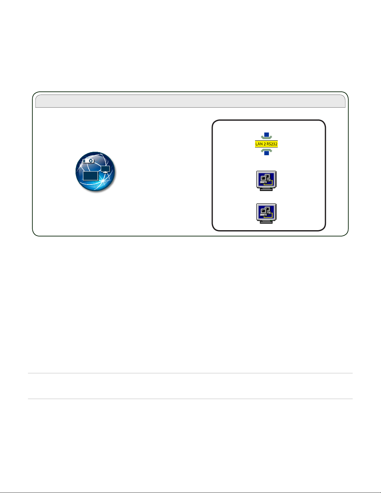
NaViSet Administrator System
Local (Administrator) Computer
NaViSet Administrator
Application
Components for Remote Computers
RS232 WMI Provider
DDC/CI WMI Provider
LAN to RS232 Bridge
Installing NaViSet Administrator
The NaViSet Administrator system includes the necessary remote software components to facilitate the various
connection methods to different devices. These components are included on the install media and are available from
the auto-run menu system, or by running the corresponding setup application directly.
NaViSet Administrator application: The main application should be installed on the administrator’s computer, and
will store all of the conguration and information gathered from the various remote devices in a local database le.
Components for Remote Computers
LAN to RS232 Bridge: Is a utility that provides two-way communications via LAN to NEC large-screen displays or
projectors that are connected to the remote computer via an RS232 connection. See Appendix D on page 130 for
more information.
DDC/CI WMI Provider: Provides two-way communications with displays connected directly to a Windows computer.
See “Desktop display(s) connected to a Windows Computer” on page 42, and Appendix F on page 136 for more
information on WMI Providers. This installer can be run in silent mode using the command line setup /S.
RS232 WMI Provider: Provides an alternate method of two-way communications with NEC large-screen displays
connected to a Windows computer via an RS232 connection. See Appendix A on page 125 for a comparison of the
various connection methods for large-screen displays and the features and benets for each. See also Appendix E on
page 133 for information on conguring settings used by the RS232 WMI Provider.
!Note: Please see the README les included with each component for detailed information on the system requirements and
conguration settings.
Page 13
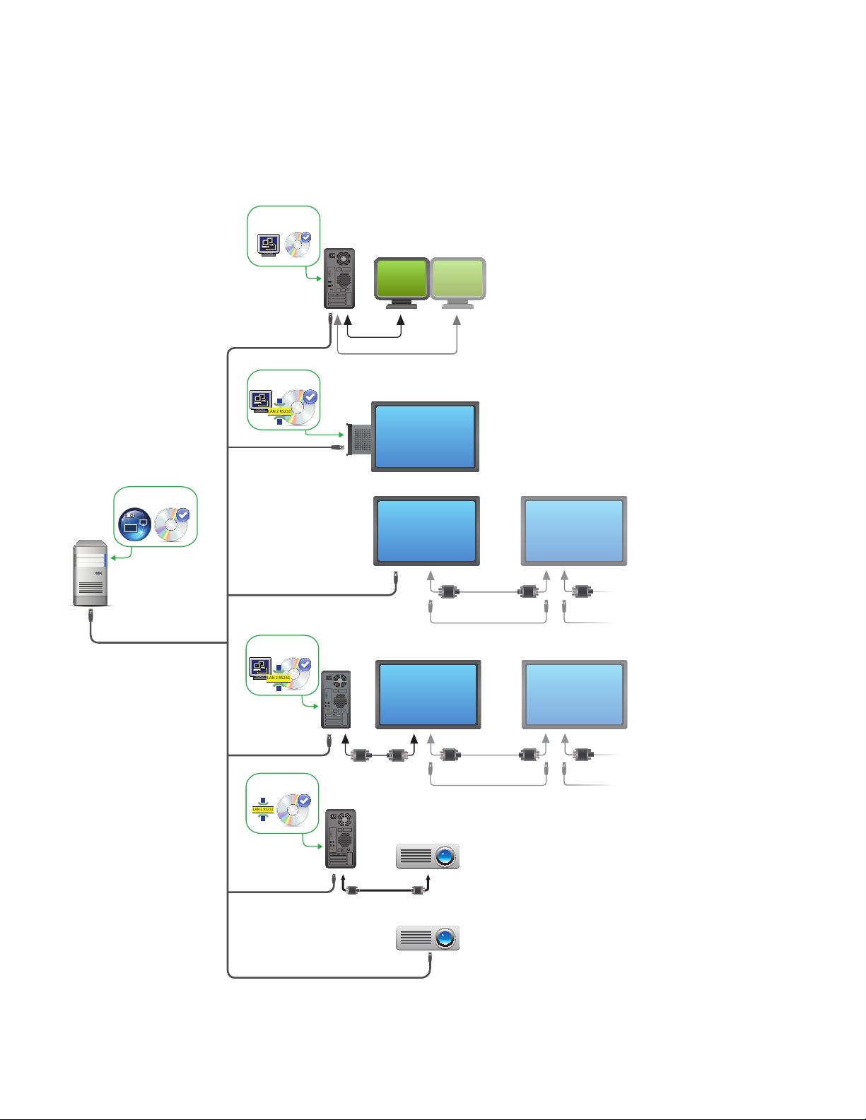
13 | NAVISET ADMINISTRATOR 2 USER’S GUIDE
LAN 2 RS232
LAN 2 RS232
LAN 2 RS232
Conguration Overview
The following diagram shows the basic different congurations of devices supported by NaViSet Administrator and the
related components that must be installed.
DDC/CI WMI Provider
(optional)
Desktop displays ¹
LAN
See page 42
}
VGA/DisplayPort/DVI connections
LAN to RS232 Bridge
or RS232 WMI Provider
Administrator’s
Computer
}
NaViSet Administrator
LAN
LAN to RS232 Bridge
or RS232 WMI Provider
LAN to RS232 Bridge
LAN
LAN
SBC
RS-232C OUT RS-232C IN RS-232C OUTLAN
LAN2 LAN1 LAN2
OR
NEC large-screen
displays
See pages 49 to 59
}
RS-232C IN RS-232C OUT RS-232C IN RS-232C OUTCOM
LAN2 LAN1 LAN2
OR
LAN
COM
¹ Includes limited support for NEC large-screen displays. See Appendix A on page 125 for details.
RS-232C
LAN
NEC projectors
See pages 61 to 62
}
Page 14
14 | NAVISET ADMINISTRATOR 2 USER’S GUIDE
Chapter
User Interface Overview
2
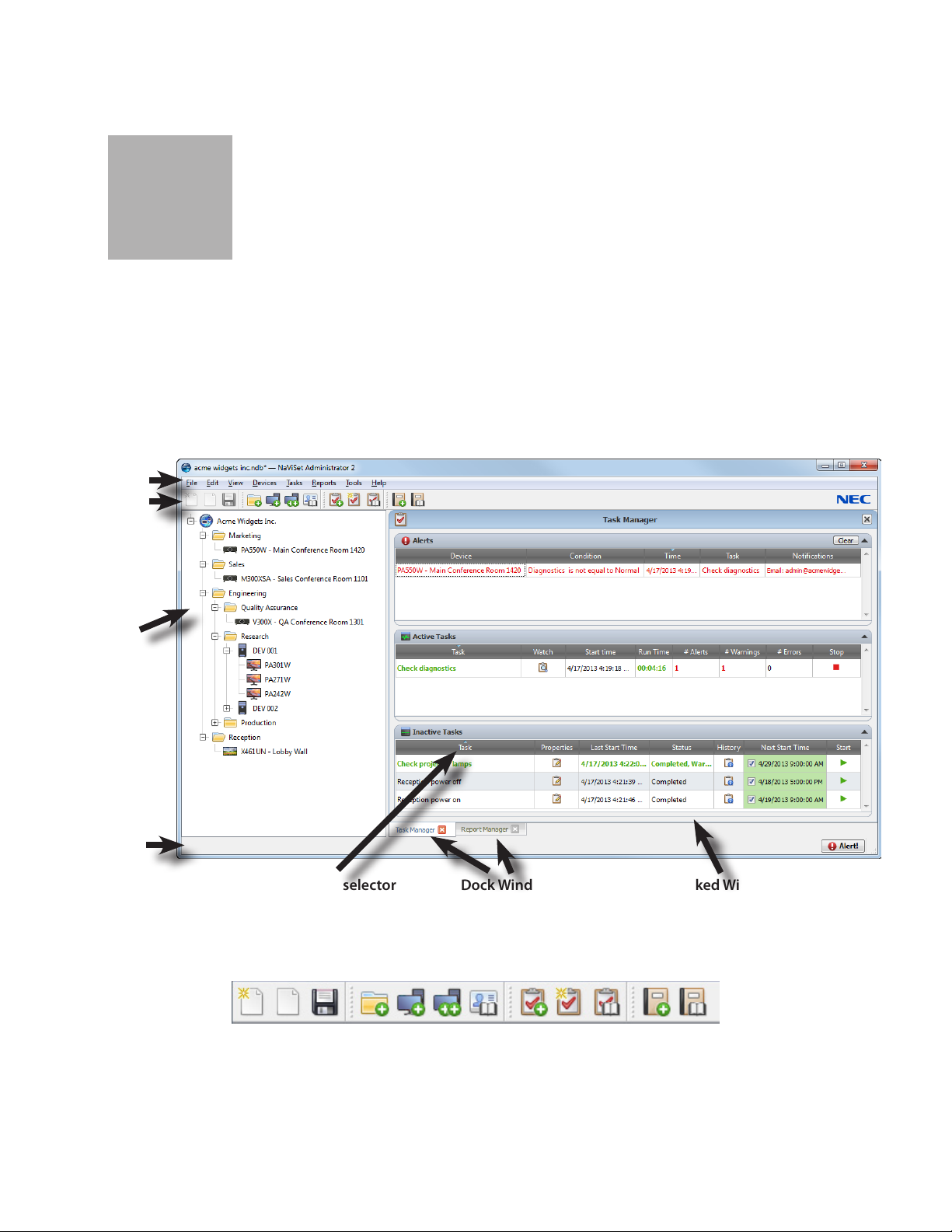
Main Window:
The main application window is divided into a Device Tree on the left and a Dock Window Area containing dock windows
on the right. Multiple dock windows are stacked on top of one another and tabbed so they can be easily identied and
selected.
By default NaViSet Administrator opens with two dock windows, Report Manager and Task Manager. There are several
other types of function-related dock windows that use this area and all are described in the appropriate sections of this
document.
Main menu
Toolbar
Device Tree
Status bar
Column sort selector
A toolbar at the top of the main window provides convenient shortcuts to many of the functions. See “Menus” on page
21 for a description of each, or mouse over the toolbar icons to see the tooltip descriptions.
A status bar at the bottom of the main window shows descriptions of menu items when selected. If enabled in the
application Preferences, the status bar also shows information about connections to devices that are currently being
processed and waiting to be processed. See “General Settings” on page 98 for more information.
Dock Window tabs
Docked Window
Page 15
15 | NAVISET ADMINISTRATOR 2 USER’S GUIDE
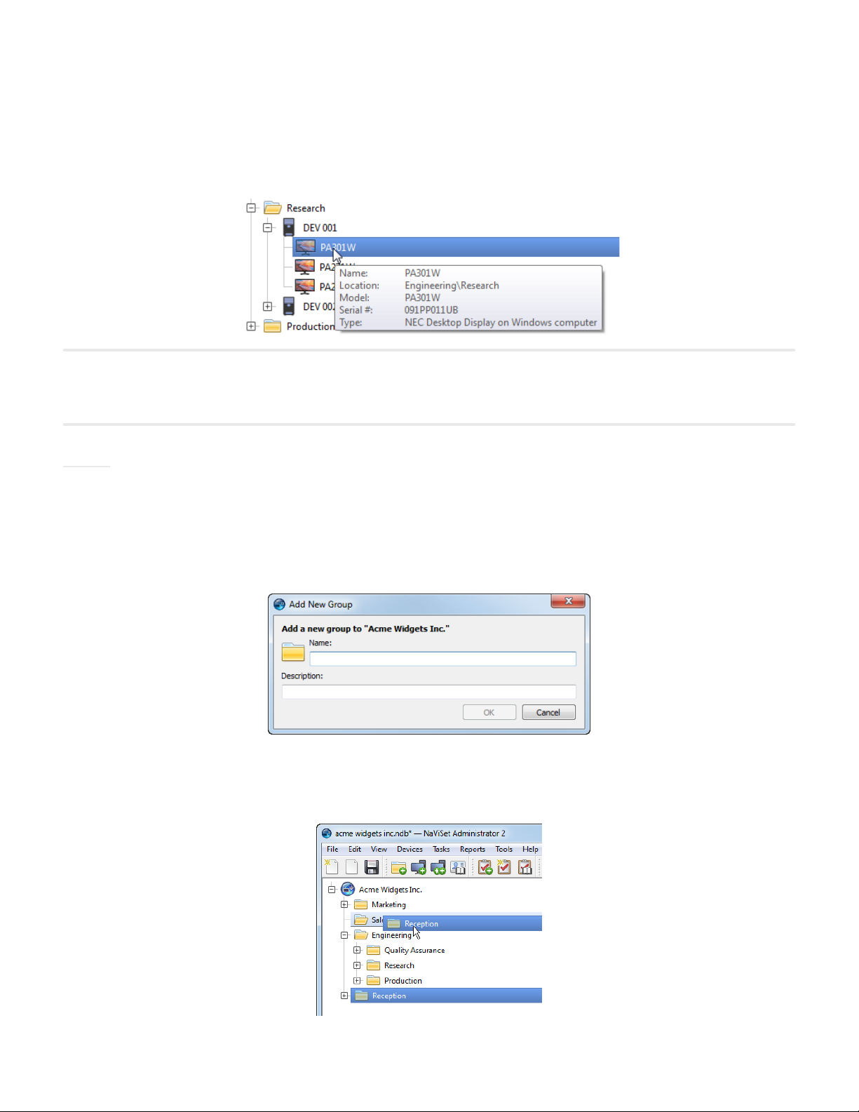
Device Tree
The Device Tree on the left of the main window represents all of the displays and computers that are in the current
database. Extra information on each device in the tree is shown in tooltips, which can be seen by mousing over each
item.
Note: The NaViset Administrator application’s User Interface can displayed in English, German, French, Japanese or Chinese
(Simplied). The default language will be selected automatically based on the computer’s language settings. The language
can be changed via the “Language” page in the “Preferences” dialog. See ”Language” on page 103 for more information.
Groups
Devices can be grouped to help organize collections of displays and computers, such as physical location (for example
by building and oor), or organizational groups (for example “Sales” and “Marketing”).
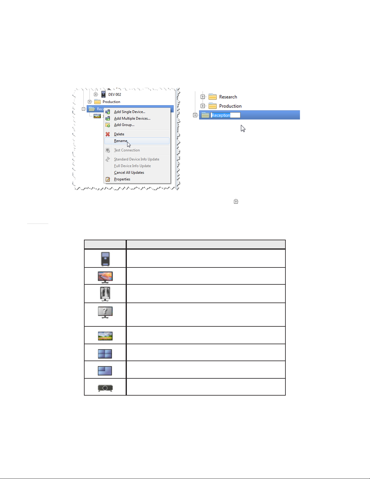
Creating Groups: Groups can be created by either selecting Add Group... from the Devices menu, or by right-click-
ing in the Device Tree and selecting Add Group.... Groups will be added as a branch to the currently selected item in
the Device Tree.
Rearranging Groups: Groups can be rearranged by clicking and dragging a Group’s folder icon to another part of the
Device Tree.
Page 16
16 | NAVISET ADMINISTRATOR 2 USER’S GUIDE
Renaming Groups: Groups can be renamed by either:
• Double-clicking the group in the Device Tree
• Right-clicking a group in the device tree and selecting Rename.
• Selecting Rename from the Edit menu while the group to be renamed is currently selected.
Expanding Groups: Groups can be expanded and collapsed by clicking the icon next to the group name.
Devices
Each device in the Device Tree is represented by an icon as shown in the following table:
Icon Description
Windows computer
NEC desktop display connected to a Windows computer
NEC medical display connected to a Windows computer
Read-only Display: A display connected to a Windows
computer with read-only connection (DDC/CI not available)
or a non-NEC display
Single NEC large-screen display
Daisy chain host: A virtual device for daisy-chained NEC
large-screen displays. See page 27 for a full description.
NEC large-screen display connected in a daisy chain
NEC projector
Page 17
17 | NAVISET ADMINISTRATOR 2 USER’S GUIDE
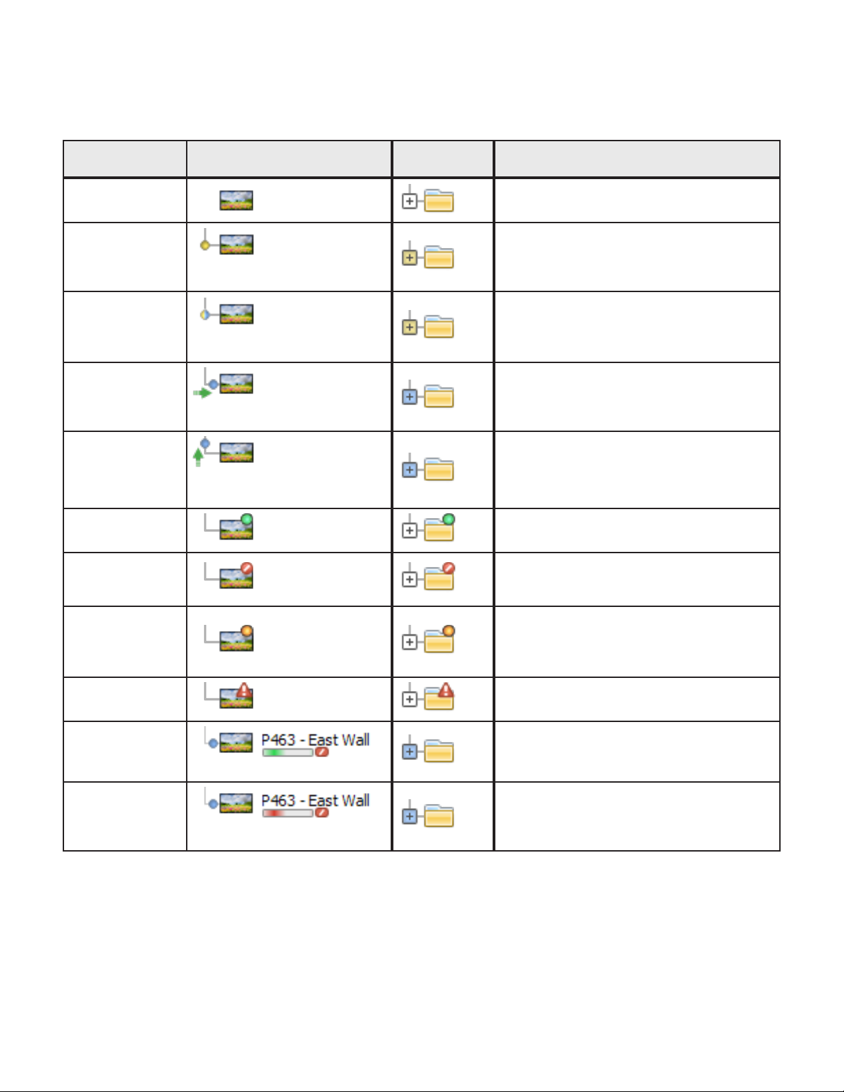
Indicators on the icons represent certain states of the devices the last time they were accessed. Current and pending
device activity is shown using various tree branch animations. The following table shows the various indicators:
Communication
Status
None
Operation
Pending
Connection Retry
Pending
Opening/Sending
Opening/
Receiving
Closed/Success
Device Containing
Pulsating yellow dot
Pulsating yellow and blue dot
Blue dot moving toward device
Blue dot moving away from
device
Description
Group
No activity between the device and the
system since the database was opened.
An operation requested by the system has
been placed in a queue until a connection
slot becomes available.
The previous attempt to connect to the
device was unsuccessful. The system is
waiting a specied time before re-submitting
the operation request into the queue.
The system is in the process of establishing
a connection and changing control settings
in the device.
The system is in the process of establishing
a connection and reading information from
the device.
The last operation between the system and
the device was successful.
Closed/Canceled
Closed/Power
State Warning
Error
Updating
Update canceling
The last operation was canceled by user.
The group icon takes precedence over
Success status.
The last operation may not have completed
successfully due to an unknown power state
condition. The group icon takes precedence
over Canceled status.
The last operation failed. The group icon
takes precedence over Warning status.
A standard update or a full update is in
progress.
Busy progress indicator -green
A standard update or a full update is in the
process of being canceled.
Busy progress indicator -red
Page 18
18 | NAVISET ADMINISTRATOR 2 USER’S GUIDE
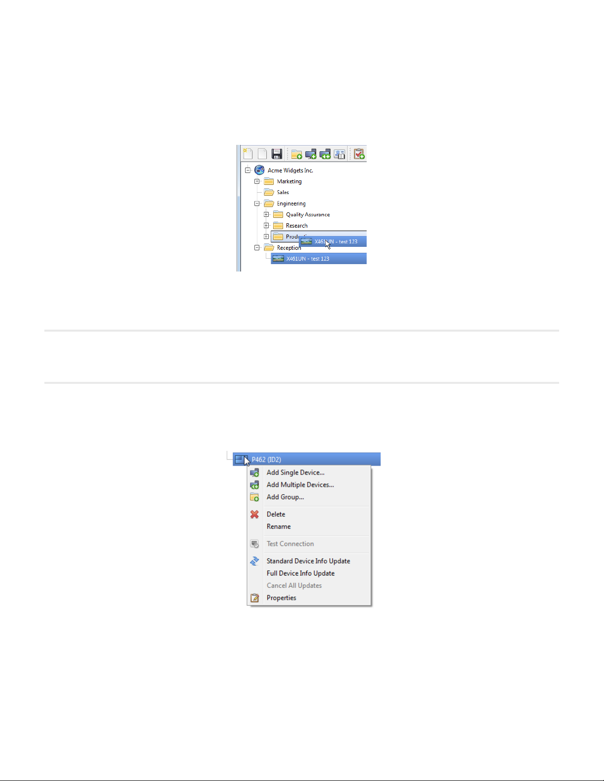
Adding Devices: Devices are added to the Device Tree by using either the Devices menu, or right-clicking an item in
the device tree and selecting either Add Single Device... or Add Multiple Devices... See page 24 for how to add
different devices.
Rearranging Devices: A device can be moved between different groups by clicking the device and dragging it onto a
different folder.
Renaming Devices: Devices can be renamed by either:
• Right-clicking on the device in the device tree and selecting Rename.
• Selecting Rename from the Edit menu while the device to be renamed is currently selected.
!Note: Renaming a device in the device tree does not change the Asset Tag stored in the display. To change the Asset Tag
stored in the display (if supported), select Asset Tag from the Display Device Information list group in the controls shown
in the Custom tab of the Device Properties window.
Opening a Device Properties Window: Double-clicking a device in the device tree will open the device’s properties
window in the dock window area. The device properties window can also be opened by right-clicking the device and
selecting Properties from the context menu.
There is no limit to the number of device properties windows that can be opened and docked at the same time.
Page 19
19 | NAVISET ADMINISTRATOR 2 USER’S GUIDE
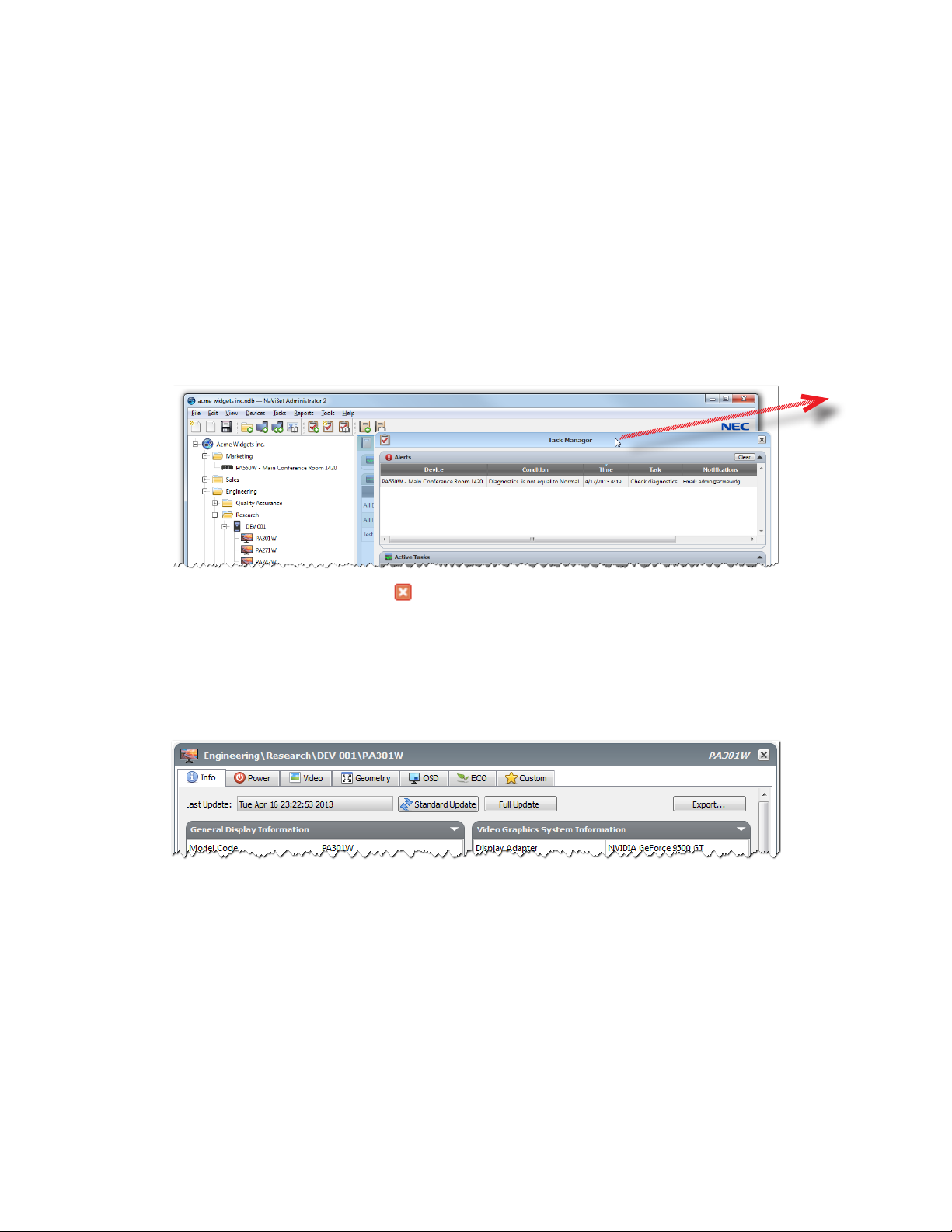
Dock Window Area
The dock window area on the right side of the main window can contain any number of Dock Windows. By default,
NaViSet Administrator opens with two docked windows, Task Manager and Report Manager. Examples of other dock
windows are Device Properties Windows and the Task History Viewer.
Device Properties Windows are opened by either double-clicking a device icon in the device tree, or right-clicking a
device and selecting Properties from the menu.
Docked windows can be moved outside the dock window area to anywhere on the desktop by clicking and dragging
the window’s title bar. Windows that are no longer docked are called oating windows. Floating windows can be moved
back into the dock window area by clicking and dragging the title bar to move the window over the dock window area.
The ability to move dock windows to anywhere on the desktop provides a lot of exibility, maximizes efcient use of the
available desktop, and allows individual items to be given prominence on the desktop if desired.
Click &
Drag Tab’s
Title Bar to
undock into
a window.
Docked windows can be closed by clicking the button on the tab list, or the x button in the dock window’s title bar.
Both docked windows and oating windows can be hidden or shown by selecting them from the View menu.
Device Properties Window
Each Device Properties Window consists of a series of tabs which divide the device information, network settings and
numerous controls into logical categories, similar to those in the device’s OSD (On Screen Display).
The number and types of tabs that appear for a device will depend on the capabilities of the device. Controls on the tabs
allow changes to be made to the device settings in real-time. Most frequently used controls are shown on individual tabs
such as Video, Audio, and Power etc. More infrequently used controls are available on the Custom tab.
See “Controlling Devices” on page 64 for a complete description of the device property tabs.
Task Manager Window
The Task Manager window shows:
• Tasks that are currently inactive (not currently being processed/executed)
• Tasks that are currently active (being processed/executed)
• Any alert conditions that have occurred while running any tasks
See “Tasks” on page 72 for more information on Tasks and the Task Manager.
Page 20

20 | NAVISET ADMINISTRATOR 2 USER’S GUIDE
Report Manager Window
The Report Manager window shows:
• Inactive Reports that are not currently being run
• Active Reports that are currently being run
See “Reports” on page 91 for more information on Reports and the Report Manager.
Page 21
21 | NAVISET ADMINISTRATOR 2 USER’S GUIDE
Menus
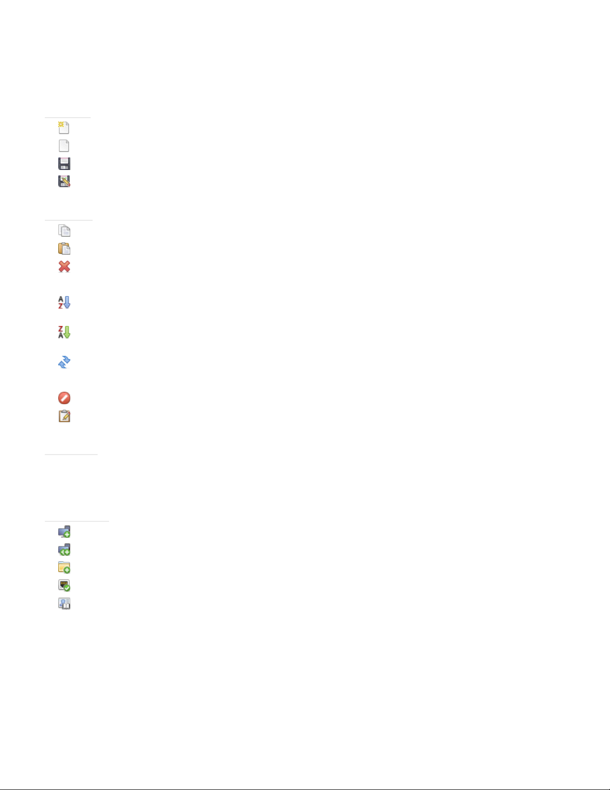
File menu
New - Creates a new database le.
Open... - Opens an existing database le.
Save - Saves the current database le.
Save As... - Saves the current database to a different le name.
Edit menu
Copy - Copies data from the currently selected table to the Windows clipboard.
Paste - Not currently used.
Delete - Deletes the currently selected group or device in the device tree.
Rename - Renames the currently selected group or device in the device tree.
Sort Group Ascending - Sorts the devices and groups within the currently selected group in the device tree.
Does not sort sub-groups.
Sort Group Descending - Reverse sorts the devices and groups within the currently selected group in the
device tree. Does not sort sub-groups.
Standard Device Info Update - Performs a Standard Update on the currently selected device tree items.
Full Device Info Update - Performs a Full Update on the currently selected devices in the device tree.
Cancel All Updates - Cancels all Standard or Full Updates that are currently being performed on any devices.
Properties - Opens the Device Properties Window for the currently selected device in the device tree.
View menu
Status Bar - Hides or shows the status bar at the bottom of the main window.
Toolbars - Hides or shows the toolbar buttons.
Devices menu
Add Single Device... - Adds a new device to the database. See “Adding Single devices” on page 24.
Add Multiple Devices... - Adds several devices to the database. See “Adding Multiple Devices” on page 30.
Add Group.... - Adds a new Group to the device tree. See “Groups” on page 15.
Test Connection - Tests the connection to a device to make sure it is accessible on the network.
Credential Library... - Opens the Credential Library. See “Credential Library” on page 70.
Page 22

22 | NAVISET ADMINISTRATOR 2 USER’S GUIDE
Tasks menu
New Task... - Creates a new Task. See “About Tasks” on page 72.
Task Builder Wizard... - Creates a new task using a wizard interface to guide.
Task Library... - Opens the Task Library. See page 73.
Show/Hide Alerts - Shows or hides the Alerts list. See page 74.
Show/Hide Active Tasks - Shows or hides the Active Tasks list. See page 74.
Show/Hide Inactive Tasks - Shows or hides the Inactive Tasks list. See page 73.
Reports menu
New Report... - Creates a new Report. See “About Reports” on page 91.
Report Library... - Opens the Report Library. See page 91.
Show/Hide Active Reports - Shows or hides the Active Reports list. See page 93.
Show/Hide Inactive Reports - Shows or hides the Inactive Reports list. See page 92.
Tools menu
Preferences - Opens the application Preferences window. See “Preferences” on page 98.
Help menu
Quick Start Guide - Opens the NaViSet Administrator Quick Start Guide using the default PDF viewer. The
Quick Start Guide will be displayed in the language NaViSet Administrator is currently using. See “Language” on
page 103 for instructions on setting the language.
User’s Guide - Opens this document using the default PDF viewer. The User’s Guide is currently available in
English only.
Check for Updates - Checks with the NEC software update system to see if a newer version is available. An
Internet connection is required.
About NaViSet Administrator 2... - Displays the software and database version information.
Page 23

23 | NAVISET ADMINISTRATOR 2 USER’S GUIDE
Chapter
Devices
3
Supported Devices
NaViSet Administrator supports the following basic types of networked devices:
• Windows computers and connected display(s), both NEC and other manufacturers
• NEC large-screen displays
• NEC projectors
A more detailed description of each of these device types is given below.
Windows computers
A networked Windows computer that is using the WMI (Windows Management Instrumentation) protocol to communicate
information about the connected displays. WMI support is built into Windows.
• See Appendix F on page 136 for a description of WMI.
This includes the following connections types:
• A Windows computer with one or more displays connected directly via VGA, DVI, HDMI, or DisplayPort.
The included DDC/CI WMI Provider may be optionally installed to provide two-way communications with
the displays. Any displays connected to the computer will automatically be detected and added to the
device tree as branches from the computer device node.
• See page 42 for details.
• A Windows computer with one or more NEC large-screen displays connected via RS232. The included
RS232 WMI Provider must be installed on the computer.
• See Appendix A on page 125 for a comparison of alternate methods of connecting large-screen displays.
• See Appendix E on page 133 for more details on conguring the RS232 WMI Provider.
• See page 55 for details on conguring the displays.
NEC large-screen displays
NEC large-screen displays using one of the following connection types:
• An NEC large-screen display that is connected via the built in LAN connection.
• See page 50 for full details.
• An NEC large-screen display that is connected via the built in LAN connection, and is also daisy-chained to
other large-screen displays via RS232 or LAN.
!Note: Daisy-chained large-screen displays are added as a single device using Add Single Device in the Devices menu.
• See page 50 for details on conguring the displays.
• An NEC large-screen display that is connected via RS232 to a Windows computer that is running the LAN
to RS232 Bridge application.
Page 24

24 | NAVISET ADMINISTRATOR 2 USER’S GUIDE
• See page 51 for details on conguring the displays.
• An NEC large-screen display that is connected via RS232 to a Windows computer that is running the NEC
LAN to RS232 Bridge application, and daisy-chained to other large-screen displays via RS232.
!Note: Daisy-chained large-screen displays are added as a single device using Add Single Device in the Devices menu.
• See page 51 for details on conguring the displays.
• An NEC large-screen display with an SBC (Single Board Computer) that is connected via the LAN
connection on the SBC.
• See page 51 for details on conguring the displays.
• An NEC large-screen display with an SBC (Single Board Computer) that is connected via the LAN
connection on the SBC, and is also daisy-chained to other large-screen displays via RS232. The SBC is
running either the LAN to RS232 Bridge application or the RS232 WMI Provider.
!Note: Daisy-chained large-screen displays are added as a single device using Add Single Device in the Devices menu.
• See page 59 for details on conguring the displays.
Projectors
An NEC projector connected to LAN using one of the following connection types:
• An NEC projector that is connected via the built in LAN connection.
• See page 61 for full details.
• An NEC projector that is connected via RS232 to a Windows computer that is running the LAN to RS232
Bridge application.
• See page 62 for full details.
Adding Devices
Devices can be added to the device tree either individually, or as multiple devices added simultaneously. When adding
a large number of devices it is recommended to use the multiple device methods.
One exception is when adding multiple large-screen displays that are daisy-chained via RS232. In this case all of the
displays are added simultaneously as one connection device, known as the daisy-chain host (see “About Daisy Chain
Hosts” on page 27), and must be added as a single device.
!Note: For the best results when adding devices, the computers and/or displays should be powered on. This will ensure all of
the information that is necessary for NaViSet Administrator to provide full functionality is read and stored in the database.
Adding Single devices
To add single devices to the device tree use either the Devices menu, or right-click an item in the device tree and select
Add Single Device..., or click the toolbar button. The Add a device to dialog will appear.
All devices added using this method must be powered on and accessible.
!Note: Devices added using this method are added to the nearest currently selected group in the device tree.
Page 25
25 | NAVISET ADMINISTRATOR 2 USER’S GUIDE
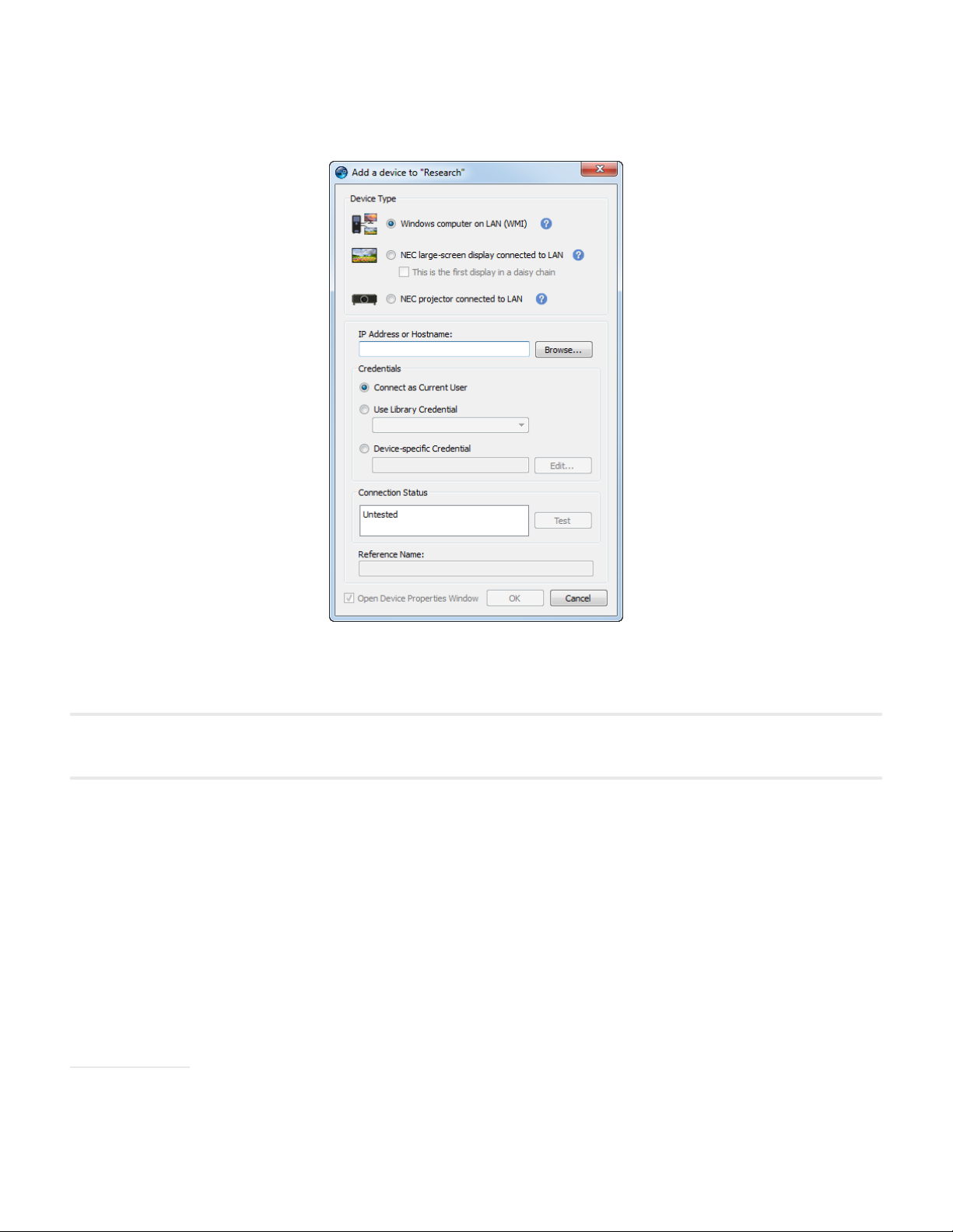
Adding a single Windows computer on LAN (WMI)
Select Windows computer on LAN (WMI).
Enter the computer’s network name or IP address, or click Browse... to view and select a computer currently available
on the LAN.
!Note: It may take several seconds after clicking the Browse... button for the dialog to appear while the network is
enumerated. Only computers that are currently available on the LAN will be shown.
If you are currently logged in as a domain administrator and have credential access to the remote computer, then select
Connect as Current User.
If the remote computer requires different credentials, then either select Use Library Credential if the credentials required
have already been added to the Credential Library, or select Device-specic Credential to enter new credentials and
optionally save to the Credential Library. See page 70 for more information on using the Credential Library.
Click the Test button to conrm the network connection. If the connection is successful, then the computer’s name will
be automatically entered into the Reference Name. The Reference Name is the name used to identify the computer in
the device tree, and can be edited if desired before it is added to the device tree, or later on by renaming the device in
the device tree.
Click OK to add the Windows computer to the device tree. Any displays connected to the Windows computer will be
detected automatically and added to the device tree under the computer node.
Troubleshooting
If an error occurred when performing the Test operation see the troubleshooting steps “Problem: Unable to connect to
a Windows Computer via WMI” on page 123.
Page 26
26 | NAVISET ADMINISTRATOR 2 USER’S GUIDE
Browse for NEC Large-Screen Display Dialog
If using the Browse function, the Browse for
NEC Large-Screen Display dialog will attempt to
automatically detect any large-screen displays that
are available on the LAN. First select the network
Interface on the computer that is connected to the
same network as the large-screen display.
Then click the Enumerate button to start the detection
process. Any detected displays will be listed by IP
address and Model Name. Select the desired display
in the list and click OK.
Not all large-screen display models support the
automatic network enumeration feature.
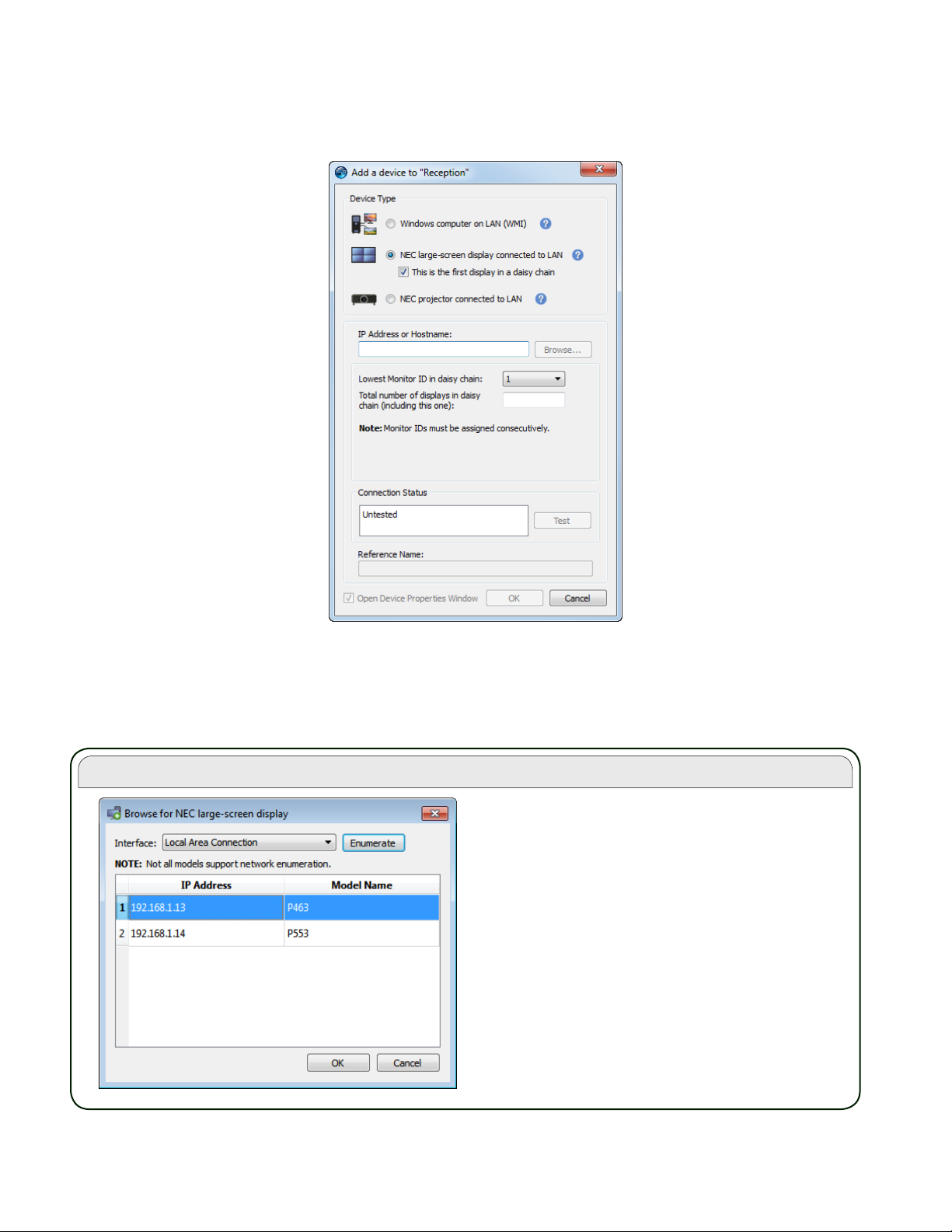
Adding NEC large-screen display(s) connected to LAN
Select NEC large-screen display connected to LAN.
Enter the IP address or hostname of the large-screen display or click Browse... to view and select a large-screen display
currently available on the LAN. If the LAN to RS232 Bridge is being used, enter the computer name or IP address of the
Windows computer to which the large-screen display is connected.
Page 27
27 | NAVISET ADMINISTRATOR 2 USER’S GUIDE
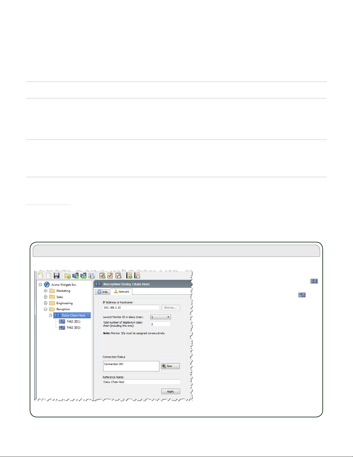
About Daisy Chain Hosts
When daisy-chained large-screen displays are
added, a virtual device called a Daisy Chain
Host is created in the device tree with the
icon. All of the actual daisy chained displays are
branches from this device with the icon .
The Daisy Chain Host device is a placeholder
for the connectivity information for the entire
daisy chain, as follows:
• IP Address or Hostname of the LAN
connection on the rst display on
the daisy chain
• Lowest Monitor ID in the daisy
chain
• Total number of displays in the
daisy chain
The Monitor IDs for each of the displays in the
daisy chain are shown in parentheses in the
display reference names in the device tree.
If the Monitor ID of the display is not known, then leave the Monitor ID selected to Auto Detect, otherwise select the
Monitor ID of the display as congured on the display’s OSD.
If the large-screen display connected to LAN also has other displays daisy-chained from it, then select This is the rst
display in a daisy chain and select the lowest Monitor ID in the daisy-chain. Next enter the Total number of displays
in the daisy-chain.
!Note: When using daisy-chains, the Monitor IDs must be numbered uniquely and sequentially.
Click Test to conrm the network connection and display detection. If the connection for a single display is successful,
then the model name will be automatically entered into the Reference Name, together with it’s Asset Tag text (if set).
If the connection for multiple displays is successful, Daisy Chain Host will be automatically entered as the reference
name. The Reference Name is the name used to identify the display in the device tree, and can be edited if desired
before it is added to the device tree, or later on by renaming the device in the device tree.
!Note: Changing the Reference Name text changes the name that will appear for the display in the device tree, and will
not change the Asset Tag stored in the display. To change the Asset Tag stored in the display, select Asset Tag from the
Display Device Information list group in the controls shown on the Custom display property tab once the display has been
added.
Click OK to add the display(s) to the device tree.
Troubleshooting
If an error occurred when performing the Test operation, see the troubleshooting steps “Problem: Unable to communicate
with an NEC large-screen display” on page 123.
Page 28
28 | NAVISET ADMINISTRATOR 2 USER’S GUIDE
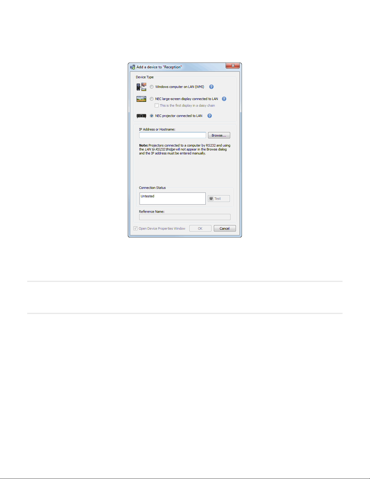
Adding a single NEC projector connected to LAN
Select NEC Projector connected to LAN.
Enter the IP address or hostname of the projector, or click Browse to automatically detect projectors that are connected
directly to the LAN.
If the LAN to RS232 Bridge is being used, enter the computer name or IP address of the Windows computer.
!Note: Projectors connected to a computer by RS232 and using the LAN to RS232 Bridge are not be able to be detected
using the Browse function. Not all projector models support the automatic network enumeration feature. In both cases the
projector or computer IP address / computer name must be entered manually.
Page 29
29 | NAVISET ADMINISTRATOR 2 USER’S GUIDE
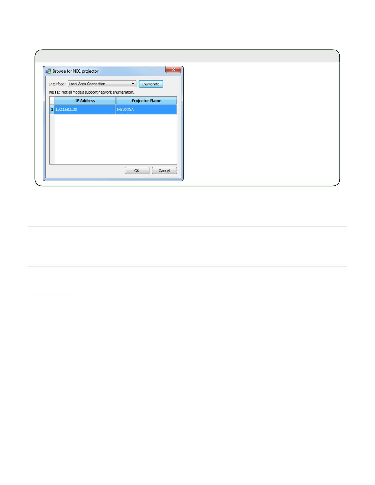
Browse for NEC Projector Dialog
If using the Browse function, the Browse for NEC
Projector dialog will attempt to automatically detect
any projectors that are available on the LAN. First
select the network Interface on the computer that is
connected to the same network as the projector.
Then click the Enumerate button to start the detection
process. Any detected projectors will be listed by IP
address and Projector Name. Select the desired
projector in the list and click OK.
Not all projector models support the automatic
network enumeration feature.
Click Test to conrm the network connection. If the connection is successful, then the model name of the projector will
be automatically entered into the Reference Name, together with it’s Asset Tag text (also known as Projector Name).
The Reference Name is the name used to identify the projector in the device tree, and can be edited if desired before it
is added to the device tree, or later on by renaming the device in the device tree.
!Note: Changing the Reference Name text, changes the name that will appear for the projector in the device tree, and will
not change the Asset Tag / Projector Name stored in the projector. To change the Asset Tag / Projector Name stored
in the projector, select Asset Tag from the Display Device Information list group in the controls shown on the Custom
display property tab once the projector has been added.
If the connection is successful, then click OK to add the projector to the device tree.
Troubleshooting
If an error occurred when performing the Test operation, see the troubleshooting steps “Problem: Unable to communicate
with an NEC projector” on page 124.
Page 30
30 | NAVISET ADMINISTRATOR 2 USER’S GUIDE
Adding Multiple Devices
If there are several devices to be added, then adding them using the Add Multiple Devices dialog is easier and more
efcient than adding one by one using the Add Single Devices function.
To add multiple devices to the device tree, use either the Devices menu, or right-click an item in the device tree and
select Add Multiple Devices... , or click the toolbar button. The Add Multiple Devices dialog will appear. Select the
type of display and connection to be added from the tabs at the top.
!Note: Large-screen displays that are daisy-chained via RS232 must be added as a single device, and cannot be added using
Multiple Devices. The only exception is when using the RS232 WMI Provider which will automatically add all connected
displays when the host computer is added.
!Note: A context menu providing operations to check or uncheck multiple devices at a time can be opened by right-clicking
on the device list.
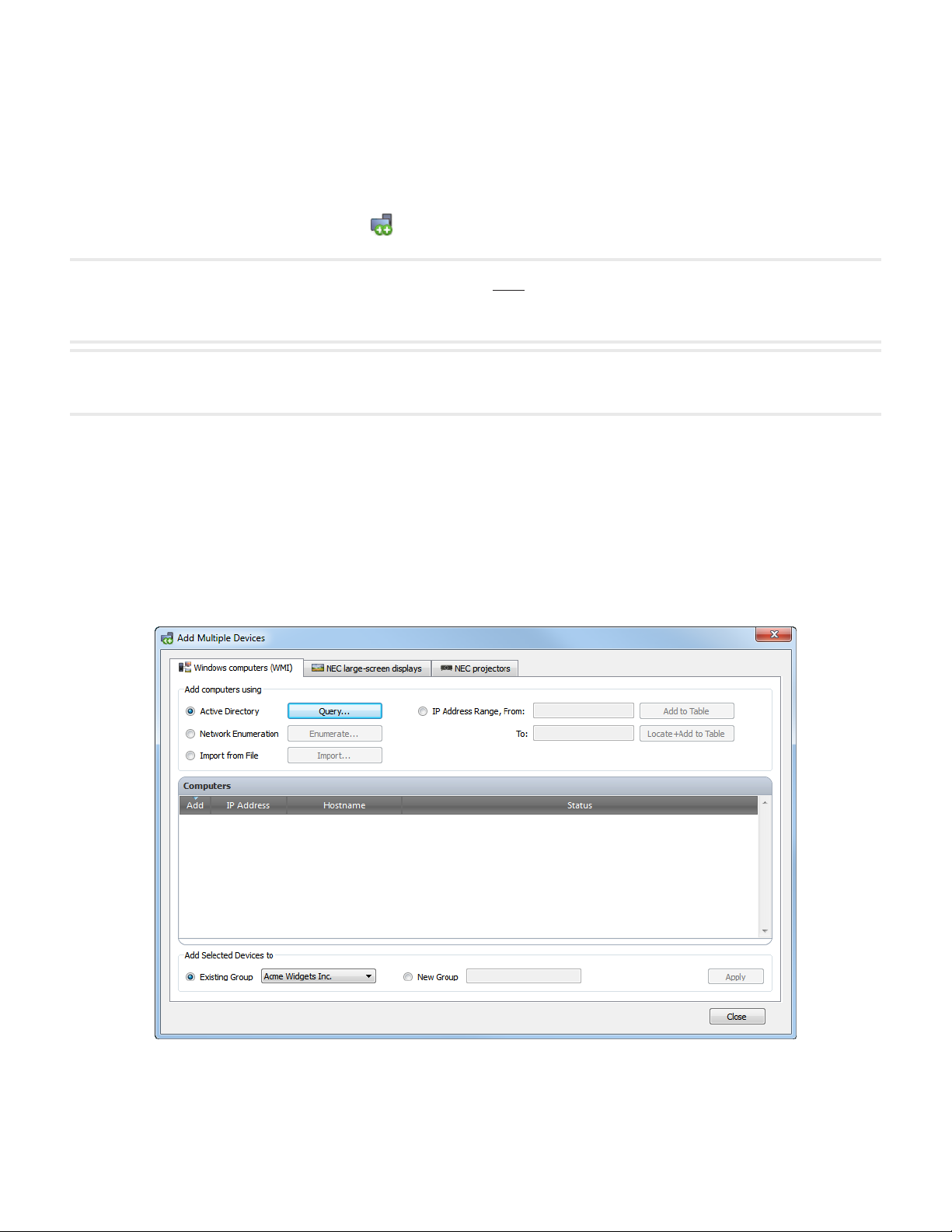
Adding multiple Windows computers (WMI)
Windows computers can be added in several different ways:
1. Active Directory
2. Network Enumeration
3. Import from File
4. IP address range
Page 31

31 | NAVISET ADMINISTRATOR 2 USER’S GUIDE
Whenever computers are added using any of the above methods, a Credentials dialog will be displayed. Access
credentials to the computer must be specied using one of the following options:
• The currently logged in user’s credentials
• An existing credential from the Credential Library (see page 70 for more information)
• A device-specic credential to be entered, and optionally added to the Credential Library
!Note: The same access Credentials are applied to all of the computers added together. To use dierent credentials on
dierent computers, add them separately by repeating this procedure.
Once the computers are added to the table, individual computers can be selected or skipped from being added to the
device tree by using the Add checkbox on each row of the table.
The computers can be added to either an existing group in the device tree or a new group, created by selecting New
Group and entering the new group name.
Click Apply to add the computers to the device tree. The computers will be queried in the background to gather
information about the computer and the connected displays.
Repeat if necessary to add other computers using different access credentials.
Page 32

32 | NAVISET ADMINISTRATOR 2 USER’S GUIDE
Active Directory Query Dialog
ADSI Object Binding - Denes the address and
credentials used to connect to the Active Directory
Server. Select Use Default unless connecting to a
different domain or credentials than the default.
Query - Sends a query to the Active Directory
Server and lists the results.
Wildcard Filters - Allows the query results to be
ltered by applying text wildcards to the Computer
Name, Description, Operating System and OS
Version columns.
Import Selected and Import All - Adds the items
to the table, after the access credentials have been
specied.
Add computers using Active Directory
If the Windows network is part of a domain with an Active Directory server, then the server can be queried to retrieve a
list of computer names in the domain. This is a fast and reliable way to add computers. The names of computers that
are currently not available on the network can be retrieved via Active Directory.
Select Active Directory and click the Query... button to open the Active Directory Query dialog.
Page 33

33 | NAVISET ADMINISTRATOR 2 USER’S GUIDE
Network Enumeration Dialog
Name: - Denes the domain or workgroup to
enumerate. The current domain/workgroup will be
used if none is entered.
Enumerate - Starts the network enumeration
process and lists the results.
Wildcard Filters - Allows the query results to be
ltered by applying text wildcards to the Computer
Name, Description, and Operating System.
Import Selected and Import All - Adds the items
to the table, after the access credentials have been
specied.
Add computers using Network Enumeration
Windows computers that are currently online on the LAN can be enumerated and added in the same way network
devices are found and shown in the Windows Network list. A computer must typically be running and have been
connected to the LAN for several minutes in order to appear in the Network Enumeration list. The network enumeration
can take up to several minutes to perform depending on the number of devices on the network.
Select Network Enumeration and click the Enumerate... button to open the Network Enumeration dialog.
Page 34

34 | NAVISET ADMINISTRATOR 2 USER’S GUIDE
Import Devices Dialog - Windows computers
Import File: - Shows the le name selected to import
the list from.
Select... - Selects the le to import from.
Select column containing IP addresses or
hostnames - Lists the column names from the
rst row of data. Select the column to use as the IP
address or hostname (computer name).
Devices - Shows all items, or rows in the currently
selected column.
Add to Table - Adds the selected items to the table,
after the access credentials have been specied.
Connectivity to the computers is not veried. Use this
to add computers that may not currently be available
on the network.
Locate + Add to Table - Adds the selected items
to the table, after the access credentials have been
specied. Connectivity to the computers is veried
as they are added. This may take several minutes to
complete if many computers are being added.
Add computers using Import from File
A list of IP addresses and/or computer names can be imported from any of the following le types:
• A column of an Excel spreadsheet le
• A delimited text le
• Another NaViSet Administrator 2 database le
Select Import from File and click the Import... button to open the Import Devices dialog.
Page 35

35 | NAVISET ADMINISTRATOR 2 USER’S GUIDE
Add computers using IP Address Range
A range of computer IP addresses can be specied and added. Enter the lower IP range in From, and the upper range
in To.
Click Add to Table to add all of the IP addresses in the range specied to the table, after the access credentials have
been specied. Connectivity to the computers is not veried. Use this to add computers that may not currently be
available on the network.
Click Locate+Add to Table to add all of the IP addresses in the range specied to the table, after the access credentials
have been specied. Connectivity to the computers is veried as they are added to the table. This may take several
minutes to complete if many computers are added.
Page 36

36 | NAVISET ADMINISTRATOR 2 USER’S GUIDE
Adding multiple NEC large-screen displays
Multiple NEC large-screen displays can be added in three different ways:
1. Automatic Network Enumeration of NEC large-screen displays on the network
2. Import from File
3. IP address range
!Note: The Monitor ID of each display is detected automatically if the display is reachable.
!Note: Large-screen displays that are daisy-chained via RS232 must be added as a single device, and cannot be added using
Multiple Devices. The only exception is when using the RS232 WMI Provider which will automatically add all connected
displays when the host computer is added.
With the large-screen displays added to the table, individual displays can be selected or skipped from being added to
the device tree by using the Add checkbox on each row of the table.
The displays can be added to either an existing group in the device tree or a new group, created by selecting New
Group and entering the new group name.
Click Apply to add the displays to the Device Tree. The displays will be queried in the background to gather information
about display settings.
Add NEC large-screen displays using Network Enumeration
Newer models of NEC large-screen displays that are connected directly to LAN are capable of being automatically
identied. A special identication message will be broadcast and list any displays that responded. First select the
network Interface to be used to send the broadcast message on, then click the Enumerate button. Any NEC large-
screen displays that were identied will be added to the list below.
Page 37

37 | NAVISET ADMINISTRATOR 2 USER’S GUIDE
Import Devices Dialog - NEC large-screen displays
Import File: - Shows the le name selected to
import the list from.
Select... - Selects the le to import from.
Select column containing IP addresses or
hostnames - Lists the column names from the
rst row of data. Select the column to use as the
IP address.
Devices - Shows all items, or rows in the currently
selected column.
Add to table - Adds the selected items to the table.
Connectivity to the displays is not veried. Use this
to add displays that may not currently be available
on the network.
Locate + Add to table - Adds the selected items to
the table. Connectivity to the displays is veried as
they are added. This may take several minutes to
complete if many displays are being added.
Add NEC large-screen displays using Import from File
A list of IP addresses can be imported from any of the following le types:
• A column of an Excel spreadsheet le
• A delimited text le
• Another NaViSet Administrator 2 database le
Select Import from File and click the Import... button to open the Import Devices dialog.
Page 38

38 | NAVISET ADMINISTRATOR 2 USER’S GUIDE
Add NEC large-screen displays using IP Address Range
A range of display IP addresses can be specied and added. Enter the lower IP range in From, and the upper range in
To.
Click Add to Table to add all of the IP addresses in the range specied to the table. Connectivity to the displays is not
veried. Use this option to add displays that may not currently be available on the network.
Click Locate+Add to Table to add all of the IP addresses in the range specied to the table. Connectivity to the displays
is veried as they are added to the table. This may take several minutes to complete if many display are added.
Once the displays are added to the table, individual displays can be selected or skipped from being added to the device
tree by using the Add checkbox on each row of the table.
The displays can be added to either an existing group in the device tree or a new group, created by selecting New
Group and entering the new group name.
Click Apply to add the displays to the Device Tree. The displays will be queried in the background to gather information
and settings.
Page 39

39 | NAVISET ADMINISTRATOR 2 USER’S GUIDE
Adding multiple NEC projectors
Multiple NEC projectors can be added in the following different ways:
1. Automatic Network Enumeration of projectors on the network
2. Importing a list of IP addresses from a le
3. Specifying an IP address range
With the projectors added to the table, individual projectors can be selected or skipped from being added to the device
tree by using the Add checkbox on each row of the table.
The device tree Group in which to add the projectors can be selected from an existing group, or a new group created by
selecting New Group and entering the new Group name.
Click Apply to add the projectors to the Device Tree. The projectors will be queried in the background to gather
information about the projector controls and settings.
Add NEC projectors using Network Enumeration
Many models of NEC projectors that are connected directly to LAN are capable of being automatically identied. A
special identication message will be broadcast and list any projectors that responded. First select the network Interface
to be used to send the broadcast message on, then click the Enumerate button. Any projectors that were identied will
be added to the list below.
!Note: Projectors connected to a computer by RS232 and using the LAN to RS232 Bridge are not be able to be detected using
the Network Enumeration function. Not all projector models support the automatic network enumeration feature.
Page 40

40 | NAVISET ADMINISTRATOR 2 USER’S GUIDE
Import Devices Dialog - NEC projectors
Import File: - Shows the le name selected to
import the list from.
Select... - Selects the le to import from.
Select column containing IP addresses or
hostnames - Lists the column names from the
rst row of data. Select the column to use as the
IP address.
Devices - Shows all items, or rows in the currently
selected column.
Add to table - Adds the selected items to the table.
Connectivity to the displays is not veried. Use this
to add displays that may not currently be available
on the network.
Locate + Add to table - Adds the selected items to
the table. Connectivity to the displays is veried as
they are added. This may take several minutes to
complete if many displays are being added.
Add NEC projectors using Import from File
A list of IP addresses can be imported from any of the following le types:
• A column of an Excel spreadsheet le
• A delimited text le
• Another NaViSet Administrator 2 database le
Select Import from File and click the Import... button to open the Import Devices dialog.
Add NEC projectors using IP Address Range
A range of display IP addresses can be specied and added. Enter the lower IP range in From, and the upper range in
To.
Click Add to Table to add all of the IP addresses in the range specied to the table. Connectivity to the projectors is not
veried. Use this option to add projectors that may not currently be available on the network.
Click Locate+Add to Table to add all of the IP addresses in the range specied to the table. Connectivity to the
projectors is veried as they are added to the table.
Page 41

41 | NAVISET ADMINISTRATOR 2 USER’S GUIDE
Chapter
Conguring Devices
4
This chapter covers how to congure all of the different supported devices so that NaViSet Administrator can successfully
connect to, query, and control them.
Desktop Displays
For desktop displays, see:
“Desktop display(s) connected to a Windows Computer” on page 42.
NEC large-screen displays
Identify the type of connection available on the model of NEC large-screen display being used, by referring to
“Conguring and connecting NEC large-screen displays” on page 45. This section explains the various different types
of connections and daisy-chain options available.
For specic information on each type of connection available on NEC large-screen displays, see:
“NEC large-screen display(s) using direct LAN connection” on page 49
“NEC large-screen display(s) with LAN hub using direct LAN connection” on page 50
“NEC large-screen display(s) using LAN to RS232 Bridge” on page 51
“NEC large-screen display(s) with LAN hub using LAN to RS232 Bridge” on page 53
“NEC large-screen display(s) using RS232 WMI Provider” on page 55
“NEC large-screen display(s) with SBC and dual LAN connections” on page 57
“NEC large-screen display with SBC and single LAN connection” on page 59
NEC Projectors
For NEC projectors, see:
“NEC projector with direct LAN or wireless connection” on page 61
“NEC projector connected via Windows Computer to LAN” on page 62
Page 42

42 | NAVISET ADMINISTRATOR 2 USER’S GUIDE
Desktop display(s) connected to a Windows Computer
Conguration Overview
One or more desktop displays connected to a Windows computer with a standard video cable. The DDC/CI WMI
Provider can be optionally installed on the computer to provide advanced information for all displays and is required for
two way control of NEC displays.
Conguration Features
1. Basic information about the main display such as Model Name and Serial Number without requiring the
DDC/CI WMI Provider to be installed.
2. Communications with the display(s) via the video graphics card and standard video cables, so no
additional cabling is required.
3. Supports WMI Scripting when using DDC/CI WMI Provider. See Appendix G on page 137.
Adding device(s) to NaViSet Administrator
Select device type Windows computer on LAN (WMI) when adding devices.
Connection Diagram
DDC/CI WMI Provider
(optional)
NaViSet Administrator
N
E
T
W
O
R
K
VGA/DisplayPort/DVI Connections
VGA Display
Note: Optional connections and devices shown in gray.
Port
Restrictions
1. KVM (Keyboard / Video / Mouse) switches, splitters, and long video cables (>3m) are not supported.
2. Support in the video graphics card driver is required for two way communications. Always update to the
latest video drivers available from the video graphics card vendor. Video drivers included by default in
Windows might not provide communications support.
3. DDC/CI WMI provider required for detailed information and information from additional displays other than
the primary display.
4. See “Windows Computer on LAN connections via WMI” on page 44 for important information about
conguring WMI.
DVI
Notes
Page 43

43 | NAVISET ADMINISTRATOR 2 USER’S GUIDE
1. Basic display information available for both NEC and third party desktop displays is available.
2. Most newer graphics cards supported. See DDC/CI WMI Provider README for latest support
information.
3. The DDC/CI WMI Provider can communicate via USB to NEC PA series of desktop displays.
4. Support for Windows computer Shutdown, Restart, Wake-on-LAN, and monitoring of computer
parameters is provided automatically.
5. Control of NEC large-screen displays is supported by DDC/CI but with some limitations. See Appendix A
on page 125 for details.
6. The DDC/CI WMI Provider cannot be installed at the same time as the RS232 WMI Provider.
Page 44

44 | NAVISET ADMINISTRATOR 2 USER’S GUIDE
Windows Computer on LAN connections via WMI
When connecting to remote Windows computers via WMI, the following important points must be veried to
ensure a successful connection:
1. The Windows user account used to access the remote computer must have sufcient access
privileges to WMI (specically the ROOT\CIMV2 namespace). Typically Administrator accounts
have sufcient access privileges by default.
2. The password for the account used to access the remote computer must not be a blank password.
3. The Windows Firewall on both the local and remote computers must allow remote access to WMI.
The default Windows Firewall settings typically block access to WMI, thus preventing remote
access to a computer.
The Windows Firewall settings for WMI can also be manually changed from the Windows Control
Panel as shown below, in order to allow remote access:
4. If the Windows computers on the network are part of a Windows Workgroup and not a Domain,
the default UAC (User Account Control) security settings will not allow access to WMI, even if
the Firewall is disabled. Installing the DDC/CI or RS232 WMI Providers on the computer will
automatically congure the security settings to allow access.
Page 45

45 | NAVISET ADMINISTRATOR 2 USER’S GUIDE
RS-232CINRS-232C
RS-232CINRS-232C
LAN
LAN1 LAN2
RS-232C
About Monitor IDs
• Each display has a Monitor ID number that is used to individually identify and address it
when used in a daisy-chain.
• Each display in a daisy-chain must have a unique Monitor ID (except for LAN daisy-chain
connections where the Auto ID function is not used).
• The Monitor ID is congured via the display’s OSD. Models that support LAN daisy-chains
can have the Monitor ID set automatically using the Auto ID function. See “Using the Auto
ID function with a LAN daisy-chain” on page 48 and the display User’s Manual for more
information.
• The Monitor ID congured in NaViSet Administrator must match the Monitor ID on each
display.
• Monitor IDs also allow displays to be individually controlled from a single IR remote control.
See the display User’s Manual for more information on using the IR Remote with multiple
displays.
Conguring and connecting NEC large-screen displays
NEC large-screen displays can be connected to the network in a variety of ways using RS232 or LAN, depending on
the model.
Also, depending on the model, displays can be daisy-chained together using RS232 or LAN cables. Daisy-chaining
displays can simplify cable wiring, and allows more than one display to be controlled from one access connection, as
well as minimizing the lengths and number of cable runs.
The following table shows the types of daisy-chains available depending on the connection conguration of the display
model being used.
Display connection
Connection description Daisy-chain type Input connection from
conguration
OUT
OUT
RS-232C IN and OUT RS232 RS232
RS-232C IN, OUT, and LAN RS232 LAN or RS232 (selectable)
RS-232C IN, LAN 1 and LAN2 LAN LAN or RS232
To determine the correct display connection conguration for the display models being used:
• Look at the physical connections on the display.
• Refer to the display’s User’s Manual.
network to rst display in
daisy-chain
Page 46

46 | NAVISET ADMINISTRATOR 2 USER’S GUIDE
RS-232CINRS-232C
LAN
LAN1 LAN2
RS-232C
RS-232CINRS-232C
RS-232CINRS-232C
LAN
The following sections describe each of the 3 basic connection types for connecting multiple NEC large-screen displays.
Connecting Directly to LAN
Supported display connection congurations
OUT
RS-232C IN, OUT, and LAN
RS-232C IN, LAN 1 and LAN2
Models that have an RJ45 LAN connection can be individually connected directly to a LAN via a hub or switch instead
of daisy-chaining displays together. This may require more wiring since each display is individually connected directly
to a central LAN hub or switch. The advantages of using this method is that communications to other displays will still
function even if:
• A display is removed from the video wall without bridging the daisy-chain.
• A display loses AC power or is turned off via the display’s main power switch.
• A display fails.
• There is a fault in cabling to an individual display.
• A display enters standby power mode and the LAN POWER setting is set to OFF (models that support
LAN daisy-chain only).
Important points to note:
• Each display must have a unique IP address.
• Since each display is addressed by the combination of IP address and Monitor ID, each display can have
the same or unique Monitor IDs.
Connecting via an RS232 Daisy-chain
Supported display connection congurations
OUT
OUT
Models that have two RS232 connections (not including any RS232 connections on OPS devices), support RS232
daisy-chaining. The connection labeled IN is the input to the display from a host computer or previous display in the
daisy-chain. The other connection labeled OUT is the output to connect to the IN on the next display in the daisy chain.
Important points to note:
• When using RS232 to connect displays using a daisy-chain, each display on the chain must have a unique
Monitor ID (set via the display’s OSD).
• Displays must be connected using an RS232 serial NULL modem cable (also known as a “crossover”
cable).
• The rst display in the daisy-chain can be connected to a host computer either via RS232, or by LAN if the
model has an RJ45 LAN connection (not including any RJ45 LAN connections on OPS devices). When
connected via LAN, the rst display can forward commands received over LAN to other displays in the
RS232 daisy-chain.
• The RS232 connection from a host computer must connect to the RS232 IN on the rst display.
RS-232C IN and OUT
RS-232C IN, OUT, and LAN
Page 47

47 | NAVISET ADMINISTRATOR 2 USER’S GUIDE
LAN1 LAN2
RS-232C
• Communications via both LAN and RS232 are not supported at the same time. The type of
communications link to use to the display must be selected by OSD setting EXTERNAL CONTROL RS232C / LAN.
Connecting via a LAN Daisy-chain
Supported display connection congurations
RS-232C IN, LAN1 and LAN2
Models that have two RJ45 LAN connections (not including any RJ45 LAN connections on OPS devices) support LAN
daisy-chaining. The RJ45 LAN connection labeled LAN1 should be used as an input to the display from the network.
The other LAN connection labeled LAN2 is the output to connect to the LAN1 on the next display in the daisy chain.
The display functions as a two port LAN hub for LAN trafc.
Important: The LAN hub function only works when AC power is applied to the display and the LAN interface is powered
on. By default the LAN POWER setting is set to turn o when the display enters a standby power mode. This will prevent
communications with other devices along the LAN daisy-chain. To prevent this, change the LAN POWER setting ON via the
OSD. This setting can also be automatically set to ON when the device is added to NaViSet Administrator if the preference
setting is selected - see “Devices” on page 102.
Displays in a LAN daisy-chain that are connected to a LAN network can be addressed in two different ways:
1. Direct (recommended):
Each display in a LAN daisy-chain can also be added to NaViSet Administrator as an individual NEC large-screen
display, rather than as part of a daisy-chain, by adding each display by it’s IP address and Monitor ID.
NaViSet Administrator will communicate directly to each display via it’s IP address.
2. Via Translation:
The rst display in a LAN daisy-chain can act as a host for commands it receives for any of the other displays further
along the daisy-chain. It will translate and forward to the relevant display any commands received via the LAN2
connection sent to it’s IP address, but with Monitor IDs for other displays in the daisy-chain.
In order to do this, the Auto ID function must be successfully performed on the rst display. The Auto ID function is
used to identify all displays along the LAN daisy-chain and assign them sequential Monitor IDs. The rst display in
the LAN daisy-chain stores a table of the IP addresses and assigned Monitor IDs for all of the other displays in the
daisy-chain.
To use this type of addressing, the displays must be added using the Add Single Device dialog and selecting This
is the rst display in a daisy chain. See “Adding NEC large-screen display(s) connected to LAN” on page 26
for more information.
IMPORTANT: Using direct addressing for each NEC large-screen display is highly recommend when using
NaViSet Administrator since it allows simultaneous communications with multiple displays, rather that having
to wait for the rst display to process communications for each display in turn within the daisy-chain.
Therefore when adding NEC large-screen displays that are daisy-chained via LAN, it is recommended
to add them individually by IP address, rather than treating them as a daisy-chain and using the “This
is the rst display in a daisy-chain”.
See the following for more information on using the Auto ID function.
Page 48

48 | NAVISET ADMINISTRATOR 2 USER’S GUIDE
Using the Auto ID function with a LAN daisy-chain
• The LAN2 RJ45 (output) of a display must connect to the LAN1 RJ45 (input) on the next display in
a daisy-chain.
• Each display must have a unique IP address assigned.
• Network hub devices must not be used to create multiple branches of displays along the LAN daisy-
chain. All displays must be connected sequentially.
• The LAN2 RJ45 of the last display in the daisy-chain must not be connected back to the network
(do not form a network loop).
• Monitor IDs are automatically assigned sequentially starting at Monitor ID 1.
• Monitor IDs are assigned based on the physical LAN cable connection order - not the IP address
assignment order.
• All displays must be powered on when performing the Auto ID function.
• The Auto ID function should only be performed from the rst display in the daisy-chain. Do not
perform Auto ID from displays further along the daisy-chain.
Page 49

49 | NAVISET ADMINISTRATOR 2 USER’S GUIDE
RS-232CINRS-232C
LAN
NEC large-screen display(s) using direct LAN connection
Supported Display Connection Congurations
OUT
RS-232C IN, OUT, and LAN
Conguration Overview
Large-screen display connected to directly LAN and using one IP address.
Conguration Features
1. Additional displays can be daisy chained from the LAN-connected display via RS232.
2. Operates without a computer.
Adding device(s) to NaViSet Administrator
Select device type NEC large-screen display connected to LAN when adding devices. See Restrictions below.
Connection Diagram
NaViSet Administrator
N
E
T
W
O
R
K
Monitor ID: 1
Control: LAN
LAN
RS-232C OUT
Monitor ID: 2
Control: RS-232C
RS-232C IN RS-232C OUT
Note: Video connections not shown for clarity.
Optional connections and devices shown in gray.
Restrictions
Notes
Ethernet / RJ45 RS232
1. Each display on the daisy-chain must have a unique Monitor ID.
2. Monitor IDs for Daisy-chained displays do not have to start at 1, but must be consecutive.
3. The rst display must be congured to use LAN. Others must be congured to use RS-232C control.
4. RS-232C cables must be crossover / NULL modem type.
5. If displays are daisy-chained, they must be added to the device tree using Add Single Device... and
selecting This is the rst display in a daisy chain.
1. RS232 splitters or Y connections are not permitted on any connection.
Page 50

50 | NAVISET ADMINISTRATOR 2 USER’S GUIDE
LAN1 LAN2
RS-232C
NEC large-screen display(s) with LAN hub using direct LAN connection
Supported Display Connection Congurations
RS-232C IN, LAN1 and LAN2
Conguration Overview
Large-screen display with internal LAN hub connected to directly LAN.
Conguration Features
1. Additional displays can be daisy-chained from the rst display via LAN using the internal LAN hub.
2. Operates without a computer.
Adding device(s) to NaViSet Administrator
Select device type NEC large-screen display connected to LAN when adding devices.
Connection Diagram
NaViSet Administrator
N
E
T
W
O
R
K
Note: Video connections not shown for clarity.
Optional connections and devices shown in gray.
LAN1
LAN2
LAN1 LAN2
Restrictions
1. Each display must have a unique IP address.
2. Monitor IDs can be the same or unique for each display.
3. If the Auto ID function is used, Monitor IDs will be assigned automatically starting at ID 1 on the rst
display. See “Using the Auto ID function with a LAN daisy-chain” on page 48 for more information.
Ethernet / RJ45
Notes
1. For maximum operation speed, it is highly recommended to treat each display as an individually
connected LAN displays in NaViSet Administrator, rather than as a daisy-chain. See page 47 for more
information.
Page 51

51 | NAVISET ADMINISTRATOR 2 USER’S GUIDE
RS-232CINRS-232C
RS-232CINRS-232C
LAN
LAN 2 RS232
NEC large-screen display(s) using LAN to RS232 Bridge
Supported Display Connection Congurations
OUT
OUT
RS-232C IN and OUT
RS-232C IN, OUT, and LAN
Conguration Overview
Windows computer with one COM port using LAN to RS232 Bridge utility, and connected to a large-screen display via
RS232.
Conguration Features
1. Uses one COM port on the host computer.
2. Additional displays can be daisy chained via RS232.
3. Fast command operation.
Adding device(s) to NaViSet Administrator
Select device type NEC large-screen display connected to LAN when adding devices. See Restrictions below.
Connection Diagram
NaViSet Administrator
N
E
T
W
O
R
K
Note: Video connections not shown for clarity.
Optional connections and devices shown in gray.
LAN to RS232 Bridge
COM
Monitor ID: 1
Control: RS-232C
RS-232C IN
RS-232C OUT
Monitor ID: 2
Control: RS-232C
RS-232C IN RS-232C OUT
Ethernet / RJ45 RS232
Restrictions
1. Monitor IDs for Daisy-chained displays do not have to start at 1, but must be consecutive.
2. Displays must be congured to use RS-232C control.
3. RS-232C cables must be crossover / NULL modem type.
4. If displays are daisy-chained, they must be added to the device tree using Add Single Device... and
selecting This is the rst display in a daisy chain.
Page 52

52 | NAVISET ADMINISTRATOR 2 USER’S GUIDE
Notes
1. Congure COM port in the LAN to RS232 Bridge utility. Select 9600 Baud Rate.
2. The Windows computer must be running and the user logged-in in order to communicate with displays.
3. The computer can also be added separately as Windows computer on LAN (WMI) to provide
shutdown, restart, Wake-on-LAN and monitoring of computer parameters.
Page 53

53 | NAVISET ADMINISTRATOR 2 USER’S GUIDE
LAN1 LAN2
RS-232C
LAN 2 RS232
NEC large-screen display(s) with LAN hub using LAN to RS232 Bridge
Supported Display Connection Congurations
RS-232C IN, LAN1 and LAN2
Conguration Overview
Windows computer with one COM port using LAN to RS232 Bridge utility, and connected to a large-screen display via
RS232.
Conguration Features
1. Uses one COM port on the host computer.
2. Additional displays can be daisy chained via LAN.
3. Fast command operation.
Adding device(s) to NaViSet Administrator
Select device type NEC large-screen display connected to LAN when adding devices. See Restrictions below.
Connection Diagram
NaViSet Administrator
N
E
T
W
O
R
K
Note: Video connections not shown for clarity.
Optional connections and devices shown in gray.
LAN to RS232 Bridge
COM
Monitor ID: 1
RS-232C IN
AUTO ID
LAN2
LAN1 LAN2
Ethernet / RJ45 RS232
Restrictions
1. Auto ID must be performed on the rst display via the display’s OSD.
2. RS-232C cable must be crossover / NULL modem type.
3. If displays are daisy-chained, the IP address settings can be set to AUTO. The displays will assign
themselves IP addresses automatically. Unique IP addresses can be used also by assigning manually via
the OSD.
4. If displays are daisy-chained, they must be added to the device tree using Add Single Device... and
selecting This is the rst display in a daisy chain.
Notes
Page 54

54 | NAVISET ADMINISTRATOR 2 USER’S GUIDE
1. Congure COM port in the LAN to RS232 Bridge utility. Select 9600 Baud Rate.
2. The Windows computer must be running and the user logged-in in order to communicate with displays.
3. The computer can also be added separately as Windows computer on LAN (WMI) to provide
shutdown, restart, Wake-on-LAN and monitoring of computer parameters.
Page 55

55 | NAVISET ADMINISTRATOR 2 USER’S GUIDE
RS-232CINRS-232C
RS-232CINRS-232C
LAN
NEC large-screen display(s) using RS232 WMI Provider
Supported Display Connection Congurations
OUT
OUT
RS-232C IN and OUT
RS-232C IN, OUT, and LAN
Conguration Overview
Windows computer with one or more COM ports using RS232 WMI Provider. Connected to one or more NEC largescreen displays via RS232.
Conguration Features
1. Supports multiple COM ports on the host computer.
2. Displays can be daisy chained via RS232.
3. Supports WMI scripting.
Adding device(s) to NaViSet Administrator
Select device type Windows Computer on LAN (WMI) when adding devices.
Connection Diagram
RS232 WMI Provider
NaViSet Administrator
N
E
T
W
O
R
K
COM 1
COM 2
Control: RS-232C
RS-232C IN
Control: RS-232C
RS-232C IN
Note: Video connections not shown for clarity.
Optional connections and devices shown in gray.
Restrictions
1. Each display on each daisy chain must have a unique Monitor ID.
Monitor ID: 1
RS-232C OUT
Monitor ID: 1
RS-232C OUT
Monitor ID: 2
Control: RS-232C
RS-232C IN
RS-232C OUT
Monitor ID: 2
Control: RS-232C
RS-232C IN
Ethernet / RJ45 RS232
RS-232C OUT
Page 56

56 | NAVISET ADMINISTRATOR 2 USER’S GUIDE
2. Congure COM ports and Monitor IDs in the RS232 WMI Provider conguration utility. See Appendix E
on page 133.
3. RS-232C cables must be crossover / NULL modem type.
4. See “Windows Computer on LAN connections via WMI” on page 44 for important information about
conguring WMI.
Notes
1. Monitor IDs do not have to start at 1.
2. Security is provided by WMI access restrictions.
3. The Windows computer must be running in order to communicate with displays.
4. For fastest performance use the LAN to RS232 Bridge or direct LAN connection.
5. See Appendix A on page 125 for comparisons between the LAN to RS232 Bridge and RS232 WMI
Provider.
6. The RS232 Provider cannot be installed at the same time as the DDC/CI WMI Provider.
Page 57

57 | NAVISET ADMINISTRATOR 2 USER’S GUIDE
RS-232CINRS-232C
LAN
NEC large-screen display(s) with SBC and dual LAN connections
Supported Display Connection Congurations
OUT
RS-232C IN, OUT, and LAN
Conguration Overview
Large-screen display with SBC (Single Board Computer) connected to the LAN. The large-screen display is also
connected to the LAN directly.
Conguration Features
1. Displays can be controlled even if the SBC is shut down or non-functional.
2. Displays can be daisy chained.
3. The SBC can run operating systems other than Windows.
Adding device(s) to NaViSet Administrator
Select device type NEC large-screen display connected to LAN when adding devices. See Restrictions below.
Connection Diagram
NaViSet Administrator
N
E
T
W
O
R
K
Note: Video connections not shown for clarity.
Optional connections and devices shown in gray.
LAN
SBC
Monitor ID: 1
Control: LAN
LAN
RS-232C OUT
Monitor ID: 2
Control: RS-232C
RS-232C IN RS-232C OUT
Ethernet / RJ45 RS232
Restrictions
1. Each display on the daisy chain must have a unique Monitor ID, and Monitor IDs must be consecutive.
2. The rst display must be congured to use LAN. Others must be congured to use RS-232C control.
3. RS-232C cables must be crossover / NULL modem type.
4. If displays are daisy-chained, they must be added to the device tree using Add Single Device... and
selecting This is the rst display in a daisy chain.
Notes
Page 58

58 | NAVISET ADMINISTRATOR 2 USER’S GUIDE
1. Monitor IDs do not have to start at 1.
2. Two IP addresses are required (one for the SBC, and one for the display).
3. The SBC can be added separately to the device tree as Windows computer on LAN (WMI) to provide
shutdown, restart, Wake-on-LAN, and monitoring of computer parameters.
Page 59

59 | NAVISET ADMINISTRATOR 2 USER’S GUIDE
RS-232CINRS-232C
RS-232CINRS-232C
LAN
LAN1 LAN2
RS-232C
LAN 2 RS232
NEC large-screen display with SBC and single LAN connection
Supported Display Connection Congurations
OUT
OUT
RS-232C IN and OUT
RS-232C IN, OUT, and LAN
RS-232C IN, LAN1 and LAN2
Conguration Overview
Large-screen display with SBC (Single Board Computer) connected to LAN, also using the internal RS-232C connection
to the SBC for communications.
Conguration Features
1. Single LAN connection using one IP address.
2. Can use either LAN to RS232 Bridge or RS232 WMI Provider.
Adding device(s) to NaViSet Administrator
When adding devices, select device type:
NEC large-screen display connected to LAN (if using LAN to RS232 Bridge)
or
Windows Computer on LAN (WMI) (if using RS232 WMI Provider)
Connection Diagram
LAN to RS232 Bridge or
RS232 WMI Provider
NaViSet Administrator
N
E
T
W
O
R
K
Note: Video connections not shown for clarity.
SBC
LAN
Restrictions
1. The LAN to RS232 Bridge or RS232 WMI Provider must be used.
Monitor ID: 1
Control: RS-232C
Internal
RS-232C
RS-232C OUT
LAN 2 OUT
2. Additional displays can not be daisy-chained from the RS232 OUT or LAN 2 (output) when using the
Page 60

60 | NAVISET ADMINISTRATOR 2 USER’S GUIDE
SBC’s internal RS-232C connection.
3. The display must be congured to use RS-232C control unless the display model supports LAN
based daisy-chains (Models supporting LAN based daisy-chains have RS-232C IN, LAN1 and LAN2
connectors).
4. Do not use the DDC/CI WMI Provider with an SBC. The internal connection to the display supports
RS232 communications only.
5. If using the RS232 WMI Provider, see “Windows Computer on LAN connections via WMI” on page 44
for important information about conguring WMI.
Notes
1. Monitor ID does not have to be 1.
2. One IP address is required.
3. The SBC must be running Windows and be operational in order to communicate with display(s).
4. See Appendix A on page 125 for comparisons between the LAN to RS232 Bridge and RS232 WMI
Provider.
Page 61

61 | NAVISET ADMINISTRATOR 2 USER’S GUIDE
NEC projector with direct LAN or wireless connection
Conguration Overview
NEC projector connected to directly LAN or wireless network.
Conguration Features
1. Single LAN connection using one IP address.
2. Operates without a computer.
Adding device(s) to NaViSet Administrator
Select device type NEC projector connected to LAN when adding devices.
Connection Diagram
NaViSet Administrator
N
E
T
W
O
R
K
LAN
Note: Video connections not shown for clarity
Notes
1. Some projector models require the communications setting to be manually congured between RS232
and LAN via the On Screen Display. Select LAN for this conguration.
Ethernet / RJ45
Page 62

62 | NAVISET ADMINISTRATOR 2 USER’S GUIDE
LAN 2 RS232
NEC projector connected via Windows Computer to LAN
Conguration Overview
NEC projector connected to a Windows computer via RS-232C, and the computer is running the LAN to RS232 Bridge
utility.
Conguration Features
1. Shared LAN connection using one IP address.
2. Supports projector models without LAN interface.
Adding device(s) to NaViSet Administrator
Select device type NEC projector connected to LAN when adding devices.
Connection Diagram
LAN to RS232 Bridge
NaViSet Administrator
N
E
T
W
O
R
K
Note: Video connections not shown for clarity
COM
RS-232C
Ethernet / RJ45 RS232
Restrictions
1. Congure the Baud rate in the LAN to RS232 Bridge utility to match that of the projector. Available rates
are 9600, 19200, and 38400 baud.
2. Some projector models require the communications setting to be manually congured between RS232
and LAN via the On Screen Display. Select RS232 for this conguration.
3. Congure the RS232 COM Port in the LAN to RS232 Bridge utility to the COM port used on the
computer.
4. Computers running the LAN to RS232 Bridge utility are not able to provide network enumeration of the
connected projector. The projector can not be automatically identied on the network using the projector
Enumerate function in NaViSet Administrator. The IP address or hostname of each computer must
therefore be manually entered instead.
5. RS-232C cable must be crossover / NULL modem type.
Page 63

63 | NAVISET ADMINISTRATOR 2 USER’S GUIDE
Notes
1. The Windows computer can also be added separately as Windows computer on LAN (WMI) to provide
shutdown, restart, Wake-on-LAN and monitoring of computer parameters.
2. The computer must be running and user logged-in in order to communicate with the projector.
Page 64

64 | NAVISET ADMINISTRATOR 2 USER’S GUIDE
Chapter
Controlling Devices
5
Devices can be controlled either interactively on an individual basis using the controls in the Device Properties Windows,
or in groups as part of a Task operation (see “Tasks” on page 72).
To control a device interactively, double-click the device icon in the device tree to open the Device Properties Window,
which will contain one or more tabs with information and controls relating to the device.
Read-only displays
Read-only displays, where two-way communications with the display is not available or supported, only have an Info
tab, and no interactive controls are available. The information shown from the display is read-only and static, such as
serial number, model name, and date of manufacture.
A display may be read-only for one or more of the following reasons:
• The DDC/CI WMI Provider has not been installed on the remote Windows computer.
• The DDC/CI WMI Provider has been installed on the remote Windows computer; however the video
graphics chipset may not support DCC/CI communications with the display.
• The input being used on the display may not support DDC/CI. For example HDMI inputs do not support
DDC/CI.
• The display is not a supported model or is not an NEC model.
Interactive Control
For devices that are not read-only, several tabs grouped into different types of controls will be shown. Controls can be
adjusted in real-time and the remote device will be updated automatically.
The available controls will depend on the type of device and the connection to the device. NaViSet Administrator will
automatically query the device to determine the capabilities and controls available.
!Note: Changes to the settings and controls on a display cannot be made when the device is in the Power O state. It must
rst be powered on before making any setting or control adjustments.
As different tabs are selected, the remote device will be queried to read the latest settings for the controls displayed
on the tab. This can take a few seconds to complete. The settings can also be read from the display and updated by
clicking the Refresh button on a tab.
The following table shows the different types of tabs that can be shown depending on the capabilities of the device
selected.
Page 65

65 | NAVISET ADMINISTRATOR 2 USER’S GUIDE
Tab Description
A summary of the most common device properties. If a Full Update
Info
Network
Power
Video
Geometry
Audio
Display Schedule
OSD
IR Remote
ECO
Custom
has been performed on the device, all of the supported control
settings from the device will be shown.
Network settings used to connect to the device such as IP address
and credentials.
Power On and Off, and other power related controls. Windows
computers include controls for Shutdown, Restart, and System
Wake-on-LAN
Controls for adjusting the video settings such as video input,
brightness, color, etc.
Controls for adjusting the positioning and scaling of the video signal
on the screen.
Audio related controls such as volume.
Controls for conguring the internal scheduling function (schedules
that run autonomously within the display) in supported large-screen
displays.
Controls for conguring settings relating to the On Screen Display
Used to send commands equivalent to pressing the buttons on the
device’s IR Remote controller. Available on large-screen displays
and projectors.
Controls relating to ECO and power saving.
Shows a list of all controls available on the device that can be
selected and adjusted. This includes more infrequently used
controls not shown on other tabs.
Info Property Tab
The Info device property tab shows a summary of the essential information about a device, such as the model name,
serial number, IP and MAC addresses, and many others depending on the device type.
When a device is rst added to the Device Tree, the basic information about the device is read and stored in the
database.
Information about a device can be updated at any time using either the Standard Update or Full Update functions (see
“Standard Update vs. Full Update” on page 69 for more details) which are available both on the Info device property
tab, and from the device tree’s context menu, shown by right-clicking on the device.
The date and time the information was last updated is shown in Last Update:. This text will be shown in red if the device
had not been updated within the last 24 hours.
The information shown on the Info tab can be exported to the clipboard, an Excel spreadsheet, or a delimited text le by
clicking the Export... button. Also information from individual tables can be copied to the clipboard by rst selecting the
desired rows in the table, then selecting Copy from the Edit menu, or by pressing Ctrl+C.
Windows Computer Info
The Info property tab for remote Windows computer devices show information about the computer such as the operating
Page 66

66 | NAVISET ADMINISTRATOR 2 USER’S GUIDE
system, service pack, CPU type, total and available RAM, and if supported by the hardware, the make, model, and serial
number of the computer.
The OS version, service pack and architecture are also shown, along with the CPU type, speed, and current usage
percentage. The installed physical memory size and currently available memory is shown.
If Open Hardware Monitor (see Appendix C on page 128) is installed on the remote computer, the CPU, GPU, and
Main Board temperatures and fan speeds will be reported if supported.
Projector or Large-screen Display Info
The Info tab includes information such as the model name, serial number, IP and MAC address of the display.
If the display supports Diagnostics reporting, or includes internal temperature sensors, these readings will be shown.
The Power On Time counter value will be shown in both hours and days if supported by the display.
Projectors that support reading the number of hours used and hours remaining on lamps and lters will show this
information also.
Desktop Display Info
For a desktop display device, the Info tab includes information about the related video graphics system on the computer
for the display, such as the display adapter model, driver version, and current video resolution settings.
If the display supports Diagnostics reporting, or includes internal temperature sensors, these readings will be shown.
The Power On Time counter, value will be shown in both hours and days if supported by the display.
Display Schedule Property Tab
This tab is shown when controlling an NEC large-screen display that supports internal schedules (schedules that run
autonomously within the display).
The schedule settings can be set for each of the 7 supported internal schedules to power the display on and off, as well
as selecting different video inputs at specic times on specic days. Once congured in the display, it will perform the
programmed schedule using the internal clock and a connection to NaViSet Administrator will not be needed.
Page 67

67 | NAVISET ADMINISTRATOR 2 USER’S GUIDE
Custom Property Tab
The Custom device property tab lists all of the controls available on the device that can be adjusted. The list includes
more infrequently used controls not shown on other tabs.
To adjust a control, select it from the Controls list and it will be added to the Settings list shown on the right side.
The remote device will be queried in real-time to read the current setting for the selected control. If an adjustment or
change is made to a control the new setting will be sent to the remote device and conrmed. This process can take a
few seconds to complete.
Multiple controls can be added to the Settings list and the order of the list can be changed using the and buttons.
Settings can be removed from the list by clicking the button.
The Settings list for a device can be saved by clicking the Save List button, and the controls shown in the list will be
restored the next time the device’s Properties Window is opened.
Page 68

68 | NAVISET ADMINISTRATOR 2 USER’S GUIDE
Some of the more unique controls available on the Custom Controls list are shown below.
Asset Tag
A custom text string can be entered and stored in the display. This text string could for example be a conventional asset
tracking code, company name, department name, phone number etc. This can then be read by NaViSet Administrator
and used for asset tracking over a network. For desktop displays and large-screen displays, this text can normally only
be altered or erased by using NaViSet Administrator. On projectors the Asset Tag is known as the Projector Name.
Only ASCII based characters can be entered and the length is limited by the capabilities of the device.
Sync Clock with System Date/Time
For large-screen displays that have an internal clock for performing schedule functions automatically, the clock can be
synchronized with the time and date from the local computer. If the display is located in another time zone, the time
applied to the display can include an offset value of from -23 to +23 hours relative to the local time. For example to
correctly set the clock for a display physically located in a time zone 2 hours ahead of the local time, select an offset of
+2 hours, and click Update.
TV Channel
For large-screen displays that have an internal TV tuner, the TV channel can be set using the TV Channel Control. Enter
the channel and sub-channel numbers and click Update to change. The TV tuner must be selected as the current video
input.
Page 69

69 | NAVISET ADMINISTRATOR 2 USER’S GUIDE
Standard Update vs. Full Update
Standard Update will read and update the basic information about a device.
For display devices, this includes items such as:
• Model Name
• Serial Number
• Date of Manufacture
• Diagnostics
• Asset Tag
For desktop displays connected to a Windows computer and accessed via WMI, additional information about
the computer and video graphics system, such as the display adapter manufacturer, model, driver version and
many more items will be shown.
Full Update will perform a Standard Update plus read and update information about all of the supported controls
and their current setting values. All of the settings read will be listed in the tables on the Info tab. Because of the
large number of controls supported on many devices, the Full Update can take over a minute depending on the
device and connection type.
!Note:
1. Performing a Standard or Full Update will overwrite all of the device information saved in
the database from the last Standard or Full Update.
2. Information for devices that are currently powered off can not be fully updated until they
are fully powered on and available for remote access.
3. When a Standard or Full Update is performed directly on a Windows computer, any new
display devices will be automatically detected and added to the device tree. If an existing
device has been disconnected or can no longer be accessed, an option to delete the
device will be given.
Page 70

70 | NAVISET ADMINISTRATOR 2 USER’S GUIDE
Chapter
Credential Library
6
About the Credential Library
Access credentials must be specied when connecting to remote Windows computers via WMI. These credentials must
be for a user with sufcient access permissions for administering the computer and accessing WMI. The credentials
consist of a Username and Password.
!Note: If the user is a member of a dierent domain than that of the computer, then the username can be specied in the
format domain\username.
NaViSet Administrator has a Credential Library feature for managing credentials and making it easier to store and apply
credentials for accessing multiple computers. This saves having to enter the same credentials again each time a new
computer is added, or needing to individually update each computer’s credentials if the administrator’s password or
username is changed. The passwords entered are encrypted and stored in the current database le.
Using the Credential Library
The Credential Library can be accessed from:
1. The Devices menu.
2. The Credential Library button on the toolbar.
3. The Network tab of a Windows computer device.
4. When using Add Single Device with a Windows Computer on LAN (WMI) device type.
5. When adding multiple Windows Computers (WMI) in Add Multiple Devices.
!Note: Credentials are not used for local connections (connections to the same computer that is running the NaViSet
Administrator application). Credentials can be entered for a local connection, however since they aren’t used, local
connections should not be used to verify administrator credentials.
Page 71

71 | NAVISET ADMINISTRATOR 2 USER’S GUIDE
Adding a new credential
Click the New.. button in the Credential Library to open the User Credential Dialog. The User name (with optional
domain specier), Password, and name alias and Description shown in the Credential Library lists can be entered.
Editing an existing credential
Click the Edit.. button in the Credential Library to open the User Credential Dialog. Changes to credentials will
automatically be applied to all device connections using the credential.
Deleting an existing credential
Click the Delete button in the Credential Library to delete a credential from the library.
Page 72

72 | NAVISET ADMINISTRATOR 2 USER’S GUIDE
Chapter
Tasks
7
About Tasks
Tasks are operations that query or perform commands on one or more devices. Tasks can be scheduled to start at
particular times or on demand. Tasks can be congured to run once or continue running for a specic period of time and
at specied intervals.
There are 3 basic types of task that can be performed in NaViSet Administrator:
• Command Tasks: Change settings or perform operations on devices. For example: Turning the display power
on, selecting a particular video input, or selecting a particular channel on the TV tuner. Command Tasks can also
be used to create a preset conguration of multiple settings that can be then sent to displays to perform easy
conguration.
• Conditional Tasks: Read one or more settings or parameters from devices at periodic intervals, and issue
alerts if any of the values are outside of a specied range or value, or changes in value. For example an alert can
be issued if the internal temperature of a display exceeds a specic value, or if a diagnostic error condition reported
by a display.
• Informational Tasks: Read one or more settings or parameters from devices at periodic intervals, and displays
the readings in real time. An example use would be to continuously monitor the internal temperature of a display.
When a Task is run it will attempt to perform the specied operation on each of the devices selected in the Task before
completing. For Conditional and Informational type tasks, the task can be set to poll the devices at specic intervals,
either indenitely, or for a specic run time.
The status of running tasks can be monitored in real-time. Upon completion, the result history of every operation is
saved in the database for use at a later time. Task history can also be exported to an Excel spreadsheet or delimited
text le, or copied to the clipboard.
Task Library
All tasks are managed using the Task Library, available on the Tasks menu or by clicking the toolbar button. Tasks
can be created, edited, duplicated, and deleted from within the Task Library. The execution history of a task can also be
viewed and exported.
Page 73

73 | NAVISET ADMINISTRATOR 2 USER’S GUIDE
Task Manager
All Tasks in the current database are listed in the Task Manager window.
This window shows:
• Tasks that are currently inactive (not currently being processed/executed)
• Tasks that are currently active (being processed/executed)
• Any alert conditions that have occurred while running any tasks
Inactive Tasks list
Inactive Tasks are tasks that are either scheduled to run and are waiting for their start time to occur, or tasks waiting to
be started manually. For Tasks that are scheduled to run, the Next Start Time is shown with a green background. The
checkbox in the Next Start Time column can be used to temporarily disable the automatic starting of a task with the
schedule. Any task can be made to start immediately by clicking the Start button.
!Note: A task will not start if its task properties dialog is opened at the same time that it is scheduled to start. Instead, it will
be rescheduled for the next start time when the dialog is closed.
The properties of a Task can be edited by clicking on the Properties button. This is the same as editing a task from
the Task Library.
The history of a task can be viewed by clicking the task History button in an inactive task. This is the same as
viewing the history from the Task Library. The task history lists the results from each time the task was executed.
Page 74

74 | NAVISET ADMINISTRATOR 2 USER’S GUIDE
For tasks that have executed during the current session, the Status column will include an icon next to the description
indicating the overall result status. The text color of the task row will also be changed and made bold. The icons and
colors used are as follows:
The task completed or was canceled without alerts, warnings or errors. Text will change to green.
A lower level warning, such as a control that is not supported by the device. Text will change to brown.
The task completed with at least one alert. This icon overrides any additional warnings or errors. Text will change
to red.
At least one error or one high level warning, such as a device connection failure. Text will change to red.
A context menu providing quick access to common task operations can be opened by right-clicking on the task. The
context menu provides these actions:
Library - Opens the Task Library with the task selected.
Properties - Opens the Task Properties dialog for review or editing.
Schedule - Opens the Task Properties dialog with the Task Schedule tab selected.
History - Opens the Task History Viewer.
Start - Starts the task.
Clear History - Permanently deletes all task history information.
Delete - Deletes the task.
Active Task list
The Active Task list shows Tasks that are currently being processed. Tasks that are congured with a schedule to start
automatically, will move from the Inactive Task list to the Active Task list while they are being processed. Once the task
has been completed, or is manually stopped, it will return to the Inactive Task list again until the next scheduled start
time is reached, or it manually started.
While a task is active, the progress of the task can be viewed in real-time by clicking the Watch button. An active
task can also be manually stopped by clicking the Stop button.
The number of alerts, warnings or errors that occur while a task is running are shown.
Alerts list
Alerts occur when a condition in a conditional type task becomes true. Alerts issued by a task are listed in the Alert list.
The Alerts list shows the task and condition that caused the Alert, the device it occurred on, the time it occurred, and
any notications that were sent.
• The Alert list contents can be permanently cleared by clicking the Clear button.
• Individual alerts can be deleted by right-clicking on the alert and selecting Delete.
• The Device Properties window can be opened directly from the Alerts table by right-clicking on the alert
and selecting Device Properties.
• Alerts messages generated during the current application session are shown with red text, and alerts
created in previous sessions are shown with normal text.
• More detailed information about a device or a notication can be seen by mousing over the device or
notication columns respectively.
• Clicking on a row in the Alerts list will automatically select the corresponding device in the Device Tree.
• Double-clicking a row while the task is running will open the Task Viewer window and select the row
Page 75

75 | NAVISET ADMINISTRATOR 2 USER’S GUIDE
containing the alert. Similarly, if the task is no longer running the Task History window will be opened.
When an alert is issued, the Alert notication button is shown at the bottom right side of the main application window.
Mouse-over the button to view details about the last alert condition. Clicking this button will open the Task Viewer
Window and select the alert.
If enabled in the application Preferences (see page 98), an Alert will also be shown in a popup message in the
Windows Task Tray:
Creating Tasks
Tasks can be created using a step-by-step wizard interface in the Task Builder Wizard, available on the Tasks menu, or
by clicking the Task Builder Wizard button. The wizard offers a guided explanation of each step of creating a task.
Tasks can also be created directly by selecting New Task... on the Tasks menu, or by clicking the New Task button,
or by selecting New... from the Task Library.
!Note: The IR Remote and Display Schedule functions are not available when using the Task Builder Wizard. To use these
functions, create a New task not using the Task Builder Wizard.
Page 76

76 | NAVISET ADMINISTRATOR 2 USER’S GUIDE
Creating a New Command Task
Command type tasks perform actions on devices such as changing control settings or performing operations.
Create a new task by selecting New Task... from the Tasks menu, or selecting New... from the Tasks Library, or click
the New Task button on the application toolbar.
Settings Tab
First give the task a name and description so it can be easily identied in the task list.
Next select the type of task to be created.
!Note: Command type tasks are only performed one time each time the task run, so the Polling Interval and Total Run Time
section is disabled.
Page 77

77 | NAVISET ADMINISTRATOR 2 USER’S GUIDE
Devices Tab
Next select the Devices tab and select at least one device that the task will be performed on. Selecting a group will
automatically select all of the devices within that group.
Devices can also be selected by model using the Select by Model listbox. Selecting a model in the list will select all
matching devices in the device tree. The button will select all devices, and the button will clear all selected devices.
Clicking the Advanced button shows additional settings for handling devices in the task.
• Maximum number of retries - Select the number of times running tasks and reports should attempt to connect
to devices.
• Timeout between retries - Enter the number of seconds to wait between each retry.
Page 78

78 | NAVISET ADMINISTRATOR 2 USER’S GUIDE
Commands Tab
Next select the Commands tab and select a control to be changed or adjusted from the control list. Once the control
has been added to the list of commands, the parameters or settings for the control can be set.
Continue adding other controls to the command list as necessary. By default, each command will be applied to all of the
devices selected in the Devices tab. Once a control is added, however, a subset of the devices can be selected using
the button.
Clicking the button for a command opens the Device Selector dialog, from which the devices to perform the
command on can be specically selected.
Page 79

79 | NAVISET ADMINISTRATOR 2 USER’S GUIDE
Multiple instances of the same control can be added, each with different devices and settings selected, thus allowing
one task to perform different control operations on different devices. See “Example Task: Using Device Specic controls
to congure a Tile Matrix” on page 114 for an example of how this functionality can be used.
!Note:
• The types of controls listed in the Commands tab depends on the types of devices selected.
• Not all devices support all of the commands and setting values listed.
• The task executes the commands on at a time, and in the order they appear in the list. For some commands the
ordering may be important, and can be changed using the and buttons.
Page 80

80 | NAVISET ADMINISTRATOR 2 USER’S GUIDE
Specic vs. Generalized Controls
NaViSet Administrator allows different types of devices and display models to be controlled in a single task. If a
group of devices is selected that are not all of the same model then a generalized version of the controls may
be automatically selected. A generalized control set is indicated by an alert window shown over the control list.
Specic controls show the actual values for a device
and the units, which closely resemble the device’s
OSD and User’s Manual.
Generalized controls typically use a percentage range
from zero to 100, which are then translated to actual
values for each device when the task is run.
!Note: Except for basic commands such as Power On/O and Audio Volume, the use of generalized controls should
be avoided. This can be done by creating separate tasks that run on similar models and/or types of devices.
Page 81

81 | NAVISET ADMINISTRATOR 2 USER’S GUIDE
Display Schedule Tab
If one or more of the devices selected is an NEC display that supports internal scheduling (schedules that run
autonomously within the display), the Display Schedule tab will be shown.
The schedule settings can be optionally set for each of the 7 supported internal schedules to power the display on and
off, as well as setting different video inputs at specic times on specic days. When the task is run it will program the
selected displays with these schedule parameters. Once the displays have been programmed via the task, it is not
necessary to use NaViSet Administrator to perform the same schedule functions since the displays will perform them
automatically using the internal clock and scheduling feature.
!Note: The display’s internal clock can be synchronized to the current date and time by using the Command “Sync Clock
with System Date/Time” control listed in the Display Device Information category. This control allows the display’s
internal clock to be set with an oset value of from -23 to +23 hours, relative to the local time. This is useful if the display
being set is located in a dierent time zone. So for example to set the internal clock for a display that is located in a time zone
two hours ahead of the current local time, set the Oset hrs value to 2. All displays in this task will be set using the same
oset value, so displays across multiple time zones should be split into separate tasks.
Page 82

82 | NAVISET ADMINISTRATOR 2 USER’S GUIDE
IR Remote Tab
If one or more devices selected supports sending IR Remote control commands, the IR Remote tab will be shown.
Sending IR Remote commands can be used to perform commands and access functions that may not be available via
the commands in the Commands tab, but are available on the device’s IR Remote control.
There are two types of remote controls, one for large-screen displays, and one for projectors. Select the appropriate
type for the device being controlled before adding any commands.
!Note: IR Remote Commands for the both display large-screen displays and projectors can not be used together in a task.
Click on the buttons in the simulated IR Remote to add them to the queue to be sent by the Task. Once buttons have
been added to the queue, the sequence they will be sent in can be rearranged or deleted using the queue arrangement
, , and buttons.
!Note: Not all displays support IR Remote commands, and not all supported displays support all if the IR controls shown. No
status or warning messages are displayed if a display does not support a particular IR Remote command.
Page 83

83 | NAVISET ADMINISTRATOR 2 USER’S GUIDE
Notications Tab
Notications allow the application to inform someone of the status of a task while they are away from the computer
that NaViSet Administrator is running on. For example an administrator may want to be notied when a very long task
involving a hundreds of devices has completed, or if an error occurred during the operation.
Select the Notication tab to congure the settings to be notied via email about the status of a task.
!Note: The Outbound Email Settings must be congured and enabled in the application Preferences in order for
notication emails to be sent.
First, click Add a Notication and select EMail Message in the Notication Type list.
In the Notication Settings dialog, enter the recipient’s email address. Insert a semicolon between addresses if multiple
email addresses are required. A supplemental message to be added to the automatically generated message text can
also be entered. Click OK when complete.
Page 84

84 | NAVISET ADMINISTRATOR 2 USER’S GUIDE
Next select the types of notications to be sent.
Options are:
• Alert Conditions - Are only available when using Conditional type tasks, and are sent when the conditions
specied in the task become true.
• Warnings - Are sent for the following conditions:
• Connection error
• Device might not be powered up
• Control or setting can not be set or read
• Task overrun
• Completion Status - Is sent once the task has completed.
To avoid a possible overwhelming number of messages being sent, message delivery can be controlled as follows:
• Send all messages immediately as they occur
• Accumulate all messages and send on task completion
• Accumulate messages and send every [user denable period]
!Note: Multiple notications can be added to each Task. This is useful if dierent recipients for dierent types of notication
conditions are necessary. For example one person may only want to be notied when a task completes, but another person
may want to be notied if there is any kind of alert or warning when the tasks runs.
Page 85

85 | NAVISET ADMINISTRATOR 2 USER’S GUIDE
Task Schedule Tab
Next click on the Task Schedule tab. This tab is used to set how and when the Task is started. Tasks can be set to run
On Demand (manually started), or using a Schedule, or as Temporary (one time task that will not be saved to the Task
Library).
To schedule the task to run at specic times or intervals, click Scheduled and select the desired Start Schedule
settings. The next time that the Task will next be automatically started is shown.
!Note: A task will not start if its task properties dialog is opened at the same time that it is scheduled to start. Instead, it will
be rescheduled for the next start time when the dialog is closed.
Summary Tab
Next, optionally click on the Summary tab to review all of the settings for the new task. Click OK to add the newly
created task to the list of tasks. The new task will be added o the task library and will also be listed in the Inactive Tasks
table in the Task Manager.
Page 86

86 | NAVISET ADMINISTRATOR 2 USER’S GUIDE
Creating Conditional Tasks
Conditional Tasks are created in the same way as other types of Tasks and are typically used to warn of abnormal
conditions in a device, or if a particular setting has changed. See the previous example for how to create a new task.
Select Conditional as the Task Type. Since this type of task is typically used to actively monitor a condition, the Polling
Interval and Total Run Time are enabled and specify how often the condition(s) should be checked while the task is
running.
The Polling Interval sets how often the devices are polled, and the Total Run Time species how long the task should
keep polling once the task has been started. If the task is to run continuously until it is stopped by the user, select No
Time Limit. Select Poll one time only if the task is to perform just one query and then stop.
!Note: Each task takes some time to complete, so care should be taken not to set a polling interval that is shorter than
the time it takes to poll all of the devices in the task. If a task is due to poll again before the previous poll has completed, a
warning message “Last Query Still Running” will be generated and the polling of all remaining devices will be skipped for
that polling interval.
Next select the Devices tab and select the devices that the Task will be performed on.
Page 87

87 | NAVISET ADMINISTRATOR 2 USER’S GUIDE
Next select the Conditions tab and select device controls that are to be checked. The list of available controls will
depend on the type of device(s) selected. Click on a control to add it to the list of conditions.
!Note: Not all devices will support all of the controls listed.
For each control that is added, an associated condition must be set. If this condition is met then a notication and/or alert
will be issued. Depending on the type of control selected, different conditions will be available.
Control Value Type Available Conditions Examples
Numerical value Exceeds, Falls Below, and Changes Temperatures, Fan Speed, Human
Sensor, Ambient Light Sensor
Binary or Named value Is, Is Not, and Changes Diagnostics, Video Input, Power State
ⓘInfo: A named value is a control setting that has discrete selections, for example the Video Input control has named values
of “Video”, “HDMI”, “DisplayPort” etc. A binary value has two states, such as “On” and “O”.
!Note: The same limitations on control values as described in the Note on page 79 applies to Conditions. The values used
to evaluate conditions may be dierent from the On Screen Display values.
If more than one condition is added, the operand used to evaluate the alert condition can be selected. AND and OR
operands are available. These operands apply to all conditions applied in the task.
If a selected device doesn’t support a control, a warning will be issued when the tasks runs on the device.
Next select and complete the Notication and Schedule tabs in the same way as the previous example.
Click OK to add the newly created task to the list of Inactive Tasks.
Page 88

88 | NAVISET ADMINISTRATOR 2 USER’S GUIDE
Creating Informational Tasks
Informational Tasks are created in the same way as other types of Tasks and are used to actively monitor one or more
device parameters.
Select Informational as the Task Type.
Since this type of task is typically used to actively monitor a parameter, the Polling Interval and Total Run Time are
enabled and specify how often the condition(s) should be checked while the task is running.
The Polling Interval sets how often the devices are polled, and the Total Run Time species how long the task should
keep polling once the task has been started.
!Note: Each task takes some time to complete, so care should be taken not to set a polling interval that is shorter than
the time it takes to poll all of the devices in the task. If a task is due to poll again before the previous poll has completed, a
warning message “Last Query Still Running” will be generated and the polling of all remaining devices will be skipped for
that polling interval.
Page 89

89 | NAVISET ADMINISTRATOR 2 USER’S GUIDE
Next select the Devices tab and select the devices that the Task will be performed on.
Next select the Query Items tab and select device controls that are to be monitored.
!Note: The list of available controls will depend on the type of device(s) selected. Not all devices will support all of the
controls listed. The same limitations on control values as described in the Note on page 79 applies to the control values
read from devices. The values shown may be dierent from the On Screen Display values.
Next select and complete the Notication and Schedule tabs.
Click OK to add the newly created task to the list of tasks.
While any task is running, the results can be viewed in real time by clicking the Watch button in the Active Task
list. A Task Viewer window will be opened that shows each device and query. The queries for individual devices can be
ltered by selecting the device from the Query Results list.
Page 90

90 | NAVISET ADMINISTRATOR 2 USER’S GUIDE
Task History
The Task History window shows the operation history for a particular Task. To view the Task History, click the button
for a task in the Inactive Tasks list, or select the desired tasks and click History... from the Task Library dialog.
The history for each time the task has been run can be selected in the Show Task Ending On: list. The Task Info list
shows a summary of the task results, including the number of alerts, errors and warnings that were encountered. The
Task History list shows the results for each device in the task. The list can be ltered by device name by selecting a
device from the listbox.
!Note:
• More detailed information about a device in the list can be seen by mousing the cursor over the
device column.
• Clicking on a row will automatically select the corresponding device in the Device Tree.
• Double-clicking a row will select the device and open the Device Properties window for the
device.
The history for the currently selected task run can be exported via the clipboard, Excel or delimited text le by clicking
the Export button.
The history for the currently selected task run can also be deleted by clicking the Delete button.
Page 91

91 | NAVISET ADMINISTRATOR 2 USER’S GUIDE
Chapter
Reports
8
About Reports
Reports are operations that gather selected setting values and information from one or more devices, and create a
report of the results.
These operations can be performed either in real-time (meaning devices are queried when the operation is run), or
using information stored in the database for each device. A hybrid query that will only query devices if the data in the
database is older than a given time period can also be specied. This option is useful to reduce unnecessary real-time
queries on devices, since they are much slower than querying the database.
The results of a report can be saved to the database, and also to an output le such as an Excel spreadsheet, or
delimited text le. When saved to the database, the report results can be viewed at any time using the Report History
viewer. Report results are stored for each time a report is generated and each can be selected, thus providing a history
of the report over time.
Example uses of reports are:
• Keeping track of computers and displays within an organization, by logging the device name, model, serial
number and asset tags.
• Keeping track of the number of operating hours that displays have been in use, the carbon savings, or any
other parameter or supported setting that can be read from a device.
Report Library
All Reports can be managed using the Report Library, available on the Reports menu, or by clicking on the toolbar
button. Reports can be created, edited, duplicated, and deleted from within the Report Library. The execution history of
a report can be viewed and exported.
Page 92

92 | NAVISET ADMINISTRATOR 2 USER’S GUIDE
Report Manager
All Reports that have been created for the current database are listed in the Report Manager tab.
This tab shows:
• Inactive Reports that are not currently running
• Active Reports that are currently running
Inactive Reports list
Inactive Reports are reports that have been created but are not currently running.
A Inactive Report can be made to start immediately by clicking the Run button, and will be moved to the Active
Reports list while it runs.
The properties of a Report can be edited by clicking on the Properties button. This is the same as editing a task
from the Report Library.
The history of a report can be viewed by clicking the Report History in an inactive report. This is the same as viewing
the history from the Report Library. The report history shows the results of each time the report has been executed.
For reports that have executed during the current session, the Status column will include an icon next to the description
indicating the overall result status. The text color of the report row will also be changed and made bold. The icons and
colors used are as follows:
The report completed or was canceled without warnings or errors. Text will change to green.
A lower level warning, such as a control that is not supported by the device. Text will change to brown.
At least one error or one high level warning, such as a device connection failure. Text will change to red.
Page 93

93 | NAVISET ADMINISTRATOR 2 USER’S GUIDE
A context menu providing quick access to common report operations can be opened by right-clicking on the report. The
context menu provides these actions:
Library - Opens the Report Library with the report selected.
Properties - Opens the Report Properties dialog for review or editing.
History - Opens the Report History Viewer.
Run - Starts and runs the report.
Clear History - Permanently deletes all report history information.
Delete - Deletes the report.
Active Reports list
Active Reports are reports that are currently being run. For Database Report types, where all of the information is being
queried from the current database, a report may be active for only a fraction of a second while it is processed. Real-
time Reports may take up to several hours to process depending on the number and type of networked devices that
are being queried. Once an Active Report has completed being processed, it will be moved to the Inactive Report list.
While a report is active, the progress of the task can be viewed in real-time by clicking the Watch button. An Active
Report can also be manually stopped by clicking the Stop button.
The number of alerts, warnings or errors that occur while a report is running are shown.
Creating Reports
Reports can be created by selecting New Report... on the Reports menu, or by clicking the New Report toolbar
button, or by selecting New... from the Report Library.
On the Settings tab, rst give the report a Name and Description so it can be identied easily in the Reports list.
Next select the type of report to be created.
Database Reports: Use the current information for each device stored in the database to create a report. No
devices are queried, so this operation is very fast, however the information may not reect the current condition
of each device. The Time Stamp column, added to reports by default, lists the date and time when the information
for each device was last updated.
Real-time Reports: Queries devices to gather the latest setting values and information. This can be selected to
always query the devices, or only query a device if the information in the database has not been updated within a
selectable time period. This is useful in order to minimize the number of device queries that are made, while at the
same time keeping the device information in the database up to date.
!Note: If a device cannot be accessed during a Real-time Report (for example if it is powered o, disconnected, network
conguration settings have changed, or is otherwise inaccessible), the icon shown in the device tree will change to show
a warning symbol. In this case, the most recent information from the database for the device will be substituted in the
report.
Whenever database data for a device is substituted in a report because the device could not be accessed, a message
“WARNING! Data May Be Out of Date” will be shown in the report’s Status column for the device. The Time Stamp
column of the report indicates the date and time of each query or database record for the device.
Page 94

94 | NAVISET ADMINISTRATOR 2 USER’S GUIDE
ⓘInfo: Whenever a Real-time report is performed on a device, the database information for the device is automatically
updated with the equivalent of performing a Standard Update. As a result any new displays connected to a Windows
computer will also be automatically detected and updated.
Next select the Devices tab and select the devices to be included in the Report. Selecting a group will automatically
select all of the devices within that group.
!Note: Windows computers and daisy-chained large-screen displays are shown in the device tree in the Devices tab without
any child devices (attached displays for Windows computers, and individual daisy-chained large-screen displays for daisychain hosts). These child devices will be determined when the Report operation is actually run, and automatically added to
the report.
Page 95

95 | NAVISET ADMINISTRATOR 2 USER’S GUIDE
Next select the Query Items tab.
The list of controls contains all of the information and settings that can be gathered from the types of devices that have
been selected.
The Query Items list contains all of the items to be queried for the selected devices. Some query items are automatically
included by default as they are necessary to uniquely identify each device in the report. The order of the items in a report
can be changed and items can be removed using the , , and buttons.
Click on a control in the list to add it to the Query Items list.
!Note: Not all devices will support all of the controls listed.
Next select the Output tab
The results of a query can be saved to the database by selecting Save results to database. This allows the results of
a particular query to be viewed later in the Report History. If this option is not selected then the results of the query will
only be available in the output format selected.
The results of a query can also be saved to a le in any of the following formats by selecting Output To File and clicking
Select... and selecting an output le name and type:
• Excel spreadsheet in .xls or .xlsx format
• Tab delimited text le
• Comma delimited text le
Page 96

96 | NAVISET ADMINISTRATOR 2 USER’S GUIDE
If an Excel spreadsheet is selected, the formatting of the spreadsheet can be selected to either Default or Plain. The
Default formatting applies cell coloring to make data easier to read.
!Note: If the Preferences setting Open report les on completion is selected, then the default application associated with
the selected le type will be used to open the le once the report has completed.
Next click the Summary tab to review the settings for the new Report. Click OK to add the newly created report to the
list of reports. It will appear in the list of Inactive Reports.
Page 97

97 | NAVISET ADMINISTRATOR 2 USER’S GUIDE
Report History
The Report History window shows the operation history for a particular Report. To view the Report History, click the
History button for a task in the Inactive Reports list, or select the desired report and click History... from the Report
Library dialog.
The history for each time the report has been run can be selected in the Show Report Ending On: list.
The Report Info list shows a summary of the report results, including the number of alerts, errors and warnings that
were encountered.
The Report Data table shows the results for each device in the task. The table data can be ltered by device type by
selecting a type from the Device Type listbox.
!Note:
• Clicking on a row will automatically select the corresponding device in the Device Tree.
• Double-clicking a row will open and select the device tab.
• Report History can be sorted by column, by selecting Enable Column Sorting and then clicking
on the header of the column to sort by. The sorting order can be reversed by clicking on the
column header again.
History for the currently selected report run can be exported via the clipboard, Excel or delimited text le by clicking the
Export button.
History for the currently selected report run can also be deleted by clicking the Delete button. History for a Report is
retained until it is deleted.
Page 98

98 | NAVISET ADMINISTRATOR 2 USER’S GUIDE
Chapter
Preferences
9
About
The Preferences dialog is used to congure many of the application settings and is accessed from the Tools menu.
Preference settings are grouped into pages which are selected using the icons on the left of the window.
Click Reset to restore the default values for all of the setting on the currently selected page.
General Settings
• Show splash screen on startup - When selected, a splash screen will be shown briey when NaViSet
Administrator is started.
• Restore application window size and position on startup - Saves and restores the application’s window size
and position.
• Show Tool Tips - When selected, Tool Tips for various controls within the application are shown when the
cursor is moused over the control.
Page 99

99 | NAVISET ADMINISTRATOR 2 USER’S GUIDE
• Show alert conditions in task tray - If an alert condition occurs, a popup message will be shown in the
Windows Task Tray.
• Show device query diagnostics in status bar - When selected, the status bar in the main window will show a
summary of the number of connections to different devices that are currently being processed, and the number
of pending connections that are waiting either for an available connection, or for another connection to the same
device to be completed. The Maximum simultaneous network connections setting sets the limit for the number
of connections that can used at one time.
!Note: Only one connection per device is allowed at a time. Therefore if there are two or more separate operations to be
performed on a device, only one will be current and the others will be pending until the running job has completed, at which
point a pending connection will become current.
• Open report les on completion - When selected, the output le (Excel or delimited text le), or Report
History window (if no output le is specied) will be automatically opened when a Report operation has
completed.
• Automatically check for software updates - When selected, the application will periodically automatically
check to see if a newer version is available by querying the NEC update servers. An Internet connection is
required.
• Don’t ask again messages: Reset - Restores the displaying of any messages that may not be being shown
because Don’t ask again was selected when they previously appeared.
• Maximum simultaneous network connections - Sets the maximum number of network connections that
can be made to different devices on the network. NaViSet Administrator can communicate to multiple devices
in parallel, which speeds up operation by allowing simultaneous connections, and allows more operations to
be performed while waiting for other devices to respond to commands. 5, 10, 20, or 30 connections can be
selected, and default value is 10 connections.
!Note: In general increasing the number of network connections increases the overall speed at which operations on large
numbers of devices can be performed. However there is a point where more connections does not give an increase in speed
due to the speed of the computer and other factors.
• Interface for Wake On Lan (WoL) Magic Packets - When using NaViSet Administrator to remotely wake up
a computer using the WoL protocol, UDP packets are broadcast from the network adapter. If the computer
running NaViSet Administrator has multiple network interfaces, for example wired and wireless, the interface to
broadcast the WoL packets from can be selected.
!Note: In order for WoL to work correctly, UDP port 9 must not be blocked by any rewalls or routers. See Appendix B on page
127 for details on conguring WoL.
Page 100

100 | NAVISET ADMINISTRATOR 2 USER’S GUIDE
Email Settings
• Enable Outbound Email Settings - When selected, NaViSet Administrator will enable the sending of
notications via email. Notications are used in Tasks to broadcast conditions such as Alerts, Errors, Warnings
and Completion of a particular Task. When not selected, all email notications are disabled.
• Email server presets - This list allows for easy conguration of the email server settings for several popular
email services. The SMTP server, port, authentication requirement, and use of SSL/TLS are congured. Other
settings such as the From Email Address, username and password must be entered. After selecting one from
the list, be sure to Test for correct operation since email service providers may change these parameters
without notice.
• From Email Address - This is the email address from which messages sent by NaViSet Administrator will be
sent.
• SMTP Server - This is the SMTP (Simple Mail Transfer Protocol) server to be used to send the email.
• Port: - This is the port to be used to contact the SMTP server. Note that some Internet Service Providers may
block certain ports such as 25 used for sending email. Check with your SMTP server to nd out which ports are
supported. Typically used ports are 25 and 587.
• Timeout (sec): - Species the timeout period when trying to send an email via the SMTP server.
• SMTP server requires authentication - Select this if the SMTP server requires that authentication credentials
be provided in order to send an email.
• Username: - The username to be used for authentication with an SMTP server. This may be in the form of an
email address depending on the server.
• Password: - The password to be used for authentication with an SMTP server.
• Use an encrypted connection (SSL/TLS) - Select this if the SMTP server requires that the authentication
credentials be encrypted by using SSL/TLS (Secure Sockets Layer / Transport Layer Security) before sending.
• Test - Conrms connectivity and credentials with the email server.
 Loading...