

Page 1

USER'S MANUAL
MultiSync
LCD1830
To learn about other special offers, register online at www.necmit subishi.com/productregistration
LCD1830.wpc 11/29/00, 9:56 AM1
®
™
Page 2
Index
Warning .................................................................................................................... 1
Contents ................................................................................................................. 2
Quick Start ............................................................................................................. 3
Controls ...................................................................................................................7
Recommended Use.............................................................................................. 10
Specifications .......................................................................................................12
Features .................................................................................................................13
Troubleshooting .................................................................................................. 14
References.............................................................................................................15
Limited Warranty.................................................................................................16
TCO’95 .................................................................................................................... 17
TCO’99.....................................................................................................................19
Avertissement ..................................................................................................... 23
Contenu................................................................................................................. 24
Mise en marche rapide ...................................................................................... 25
Commandes .......................................................................................................... 29
Usage recommandé ............................................................................................ 32
Fiche technique ................................................................................................... 34
Fonctions .............................................................................................................. 35
Dépannage ............................................................................................................ 36
Références ........................................................................................................... 37
Garantie limitée .................................................................................................. 38
TCO’95 ................................................................................................................... 39
TCO’99.................................................................................................................... 41
Warnung ............................................................................................................... 45
Lieferumfang ....................................................................................................... 46
Quick Start ........................................................................................................... 47
Bedienungselemente ......................................................................................... 51
Empfehlungen für die Verwendung ................................................................ 55
Technische Daten ............................................................................................... 57
Funktionen ......................................................................................................... 58
Fehlerbehebung ................................................................................................. 59
Verweise............................................................................................................... 60
Beschränkte Gewährleistung ........................................................................... 61
TCO’95 ................................................................................................................... 62
TCO’99................................................................................................................... 64
LCD1830.wpc 11/29/00, 9:56 AM2
Page 3
WARNING
TO PREVENT FIRE OR SHOCK HAZARDS, DO NOT EXPOSE THIS UNIT TO RAIN OR MOISTURE. ALSO, DO NOT USE
THIS UNIT'S POLARIZED PLUG WITH AN EXTENSION CORD RECEPTACLE OR OTHER OUTLETS UNLESS THE PRONGS
CAN BE FULLY INSERTED.
REFRAIN FROM OPENING THE CABINET AS THERE ARE HIGH VOLTAGE COMPONENTS INSIDE. REFER SERVICING
TO QUALIFIED SERVICE PERSONNEL.
CAUTION
CAUTION: TO REDUCE THE RISK OF ELECTRIC SHOCK, MAKE SURE POWER CORD IS UNPLUGGED FROM
WALL SOCKET. TO FULLY DISENGAGE THE POWER TO THE UNIT, PLEASE DISCONNECT THE POWER
CORD FROM THE AC OUTLET.DO NOT REMOVE COVER (OR BACK). NO USER SERVICEABLE PARTS
INSIDE. REFER SERVICING TO QUALIFIED SERVICE PERSONNEL.
This
symbol warns user that uninsulated voltage within the unit may have sufficient magnitude to cause
electric shock. Therefore, it is dangerous to make any kind of contact with any part inside this unit.
This symbol alerts the user that important literature concerning the operation and maintenance of this
unit has been included. Therefore, it should be read carefully in order to avoid any problems.
Canadian Department of Communications Compliance Statement
DOC: This Class B digital apparatus meets all requirements of the Canadian
Interference-Causing Equipment Regulations.
C-UL: Bears the C-UL Mark and is in compliance with Canadian Safety Regulations
according to C.S.A. C22.2 No. 950.
FCC Information
1.
Use the attached specified cables with the
BK) color monitor so as not to interfere with radio and television reception.
(1)
Please use the supplied power cord or equivalent to ensure FCC compliance.
(2) Please use the supplied shielded video signal cable, 15-pin mini D-SUB to
15-pin mini D-SUB.
2.
This equipment has been tested and found to comply with the limits for a Class B digital
device, pursuant to part 15 of the FCC Rules. These limits are designed to provide
reasonable protection against harmful interference in a residential installation. This
equipment generates, uses, and can radiate radio frequency energy, and, if not installed
and used in accordance with the instructions, may cause harmful interference to radio
communications. However, there is no guarantee that interference will not occur in a
particular installation. If this equipment does cause harmful interference to radio or
television reception, which can be determined by turning the equipment off and on, the user
is encouraged to try to correct the interference by one or more of the following measures:
• Reorient or relocate the receiving antenna.
• Increase the separation between the equipment and receiver.
• Connect the equipment into an outlet on a circuit different from that to which the receiver
is connected.
• Consult your dealer or an experienced radio/TV technician for help.
MultiSync LCD1830
(LA-18S02 and LA-18S02-
If necessary, the user should contact the dealer or an experienced radio/television technician
for additional suggestions. The user may find the following booklet, prepared by the Federal
Communications Commission, helpful: ”How to Identify and Resolve Radio-TV Interference
Problems.“ This booklet is available from the U.S. Government Printing Office, Washington,
D.C., 20402, Stock No. 004-000-00345-4.
1
LCD1830.wpc 11/29/00, 9:56 AM3
Page 4

Contents
Your new NEC MultiSync® LCD monitor box* should contain the
following:
• MultiSync LCD1830™ monitor with tilt base
• Power Cord
• Video Signal Cable
• User’s Manual
USER'S MANUAL
MultiSync
LCD1830
To learn about other special offers, register online at www.necmitsubishi.com/productregistration
* Remember to save your original box and packing material to transport or ship the monitor.
®
™
2
LCD1830.wpc 11/29/00, 9:56 AM4
Page 5
Quick Start
To attach the MultiSync® LCD monitor to your system, follow these
instructions:
1. Turn off the power to your computer.
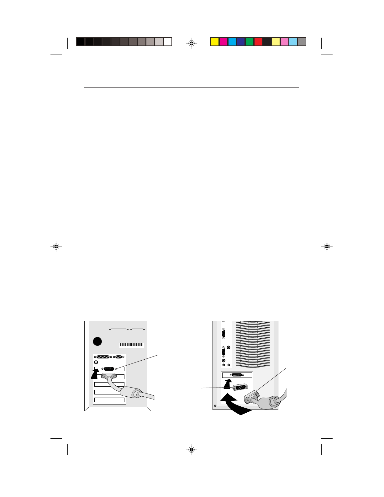
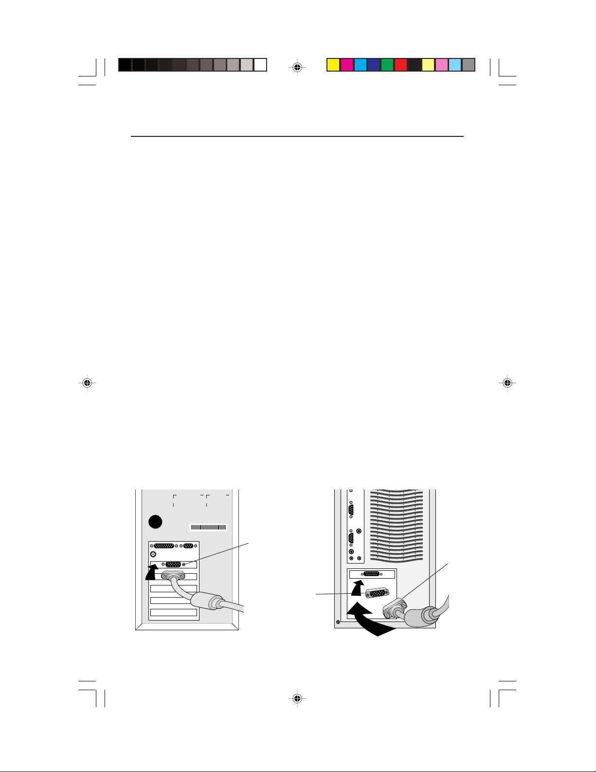
2. For the PC: Connect the 15-pin mini D-SUB of the appropriate signal cable
to the connector of the display card in your system (Figure A.1). Tighten all screws.
For the Mac: Connect the MultiSync LCD
(Figure B.1). Attach the 15-pin mini D-SUB end of the appropriate signal cable to the
MultiSync LCD
NOTE: To obtain the MultiSync LCD
Electronics Display of America, Inc. at (800) 820-1230.
Remove connector cover and cable cover on back of monitor.
3. Connect the 15-pin mini D-SUB of the video signal cable to the connector “INPUT 1” OR
“INPUT 2” on the back of the monitor (Figure C.1).
NOTE: Incorrect cable connections may result in irregular operation, damage
display quality/components of LCD module and/or shorten the module’s life.
4. Connect one end of the power cord to the MultiSync LCD Series monitor and the other
end to the power outlet. (Figure C.1). Replace connector cover and cable cover
(Figure E.1).
NOTE: If you use this monitor at AC220-240V, please refer to Recommended Use
section of this manual for proper selection of AC power cord.
5. Turn on the monitor (Figure D.1) and the computer.
6.
To complete the setup of your MultiSync LCD monitor, use the following OSM™ controls:
• Auto Adjust Contrast
• Auto Adjust
Refer to the Controls section of this User’s Manual for a full description of these OSM controls.
NOTE: For download information on the Windows 95/98 INF file for your MultiSync
LCD
NOTE: If you have any problems, please refer to the Troubleshooting section of
this User’s Manual.
NOTE: For easy removal of the cable cover or signal cable, place the monitor face down (Figure R.2).
1830 Macintosh cable adapter (Figure B.1). Tighten all screws.
1830 Macintosh cable adapter, call NEC-Mitsubishi
1830 monitor, refer to the References section of this User’s Manual.
™
1830
Macintosh cable adapter to the computer
Figure A.1 Figure B.1
LCD1830.wpc 11/29/00, 9:56 AM5
15-pin
mini D-SUB
Mac Adapter
(not included)
15-pin
mini
D-SUB
3
Page 6

Quick Start –continued
Figure C.1
AC Power
Cord
Signal
Cable
1. Cables pass through in this hole.
2. Connect each connector
3. Replace connector cover with cables
passing through upper opening
.
Power Outlet
LCD1830.wpc 11/29/00, 9:56 AM6
Power Switch
Figure D.1
4
To Computer
INPUT2
INPUT1
AC-IN
Page 7

Quick Start –continued
2
3
1
Marking
Marking area
(1.Push)
2
1
Push
Figure E.1
Cable Cover
How to remove this cover.
1. Push marking area
2. Slide to up side
Remove
3.
1
Push
Connector Cover
How to remove this cover.
1. Push under side
2. Remove
LCD1830.wpc 11/29/00, 9:56 AM7
5
Page 8
Quick Start –continued
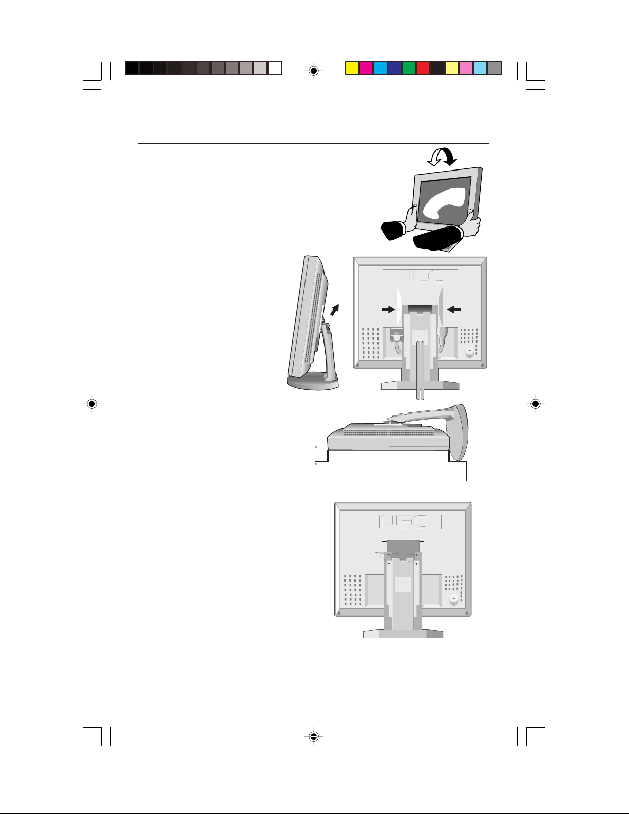
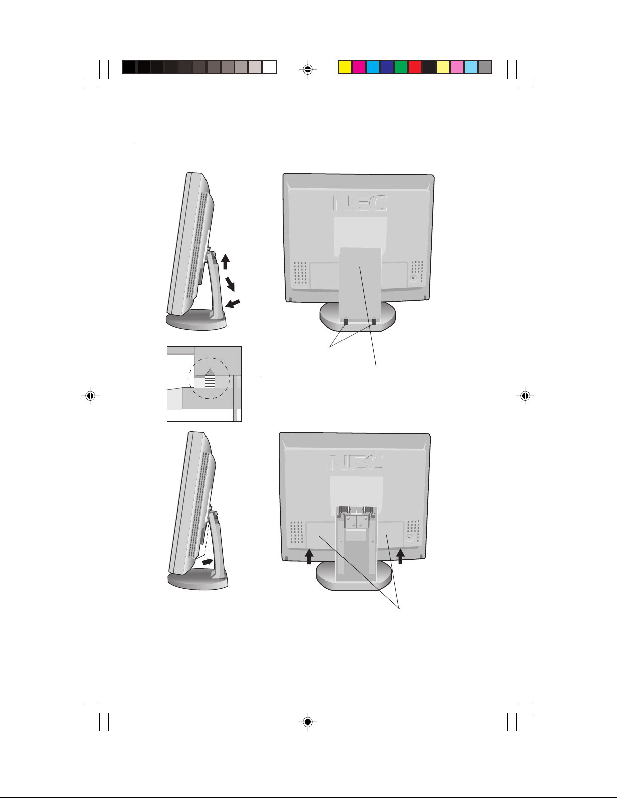
Tilt
Grasp both sides of the monitor screen with your hands
and adjust the tilt as desired (Figure TS.1).
Remove Monitor Stand for Mounting
Figure TS.1
To prepare the monitor for alternate mounting purposes:
1. Remove the connector cover, hinge cover
and cable cover
(Figure R.1).
2. Disconnect all cables.
3. Place monitor face down
on a non-abrasive
surface ( place the screen
on a 32 mm platform so
PUSH
that hole of stand match to
screw location).
(Figure R.2).
4. Remove the 4 screws
connecting the
monitor to the stand
and lift off the stand assembly
(Figure R.2)
the monitor is
Figure R.1
now ready for mounting in an
alternate manner.
5. Connect the AC cord and signal
cable to the back of the monitor.
6. Reverse this process to
32mm
reattach stand.
PUSH
Figure R.2
Caution:
LCD1830.wpc 11/29/00, 9:56 AM8
To fulfil the safety requirements
the monitor must be mounted to
an arm which guaranties the
necessary stability under
consideration of the weight of the
monitor. The LCD monitor shall
only be used with an approved
arm (e.g. GS mark).
Screws
6
Page 9
Controls
OSM™ (On-Screen Manager) control buttons on the front of the
monitor function as follows:
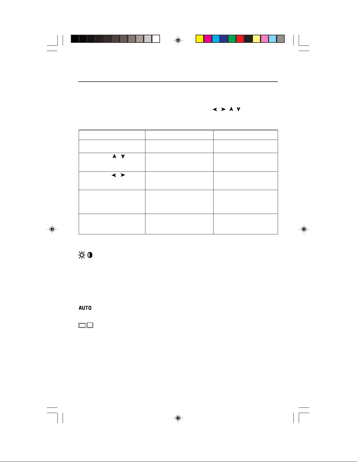
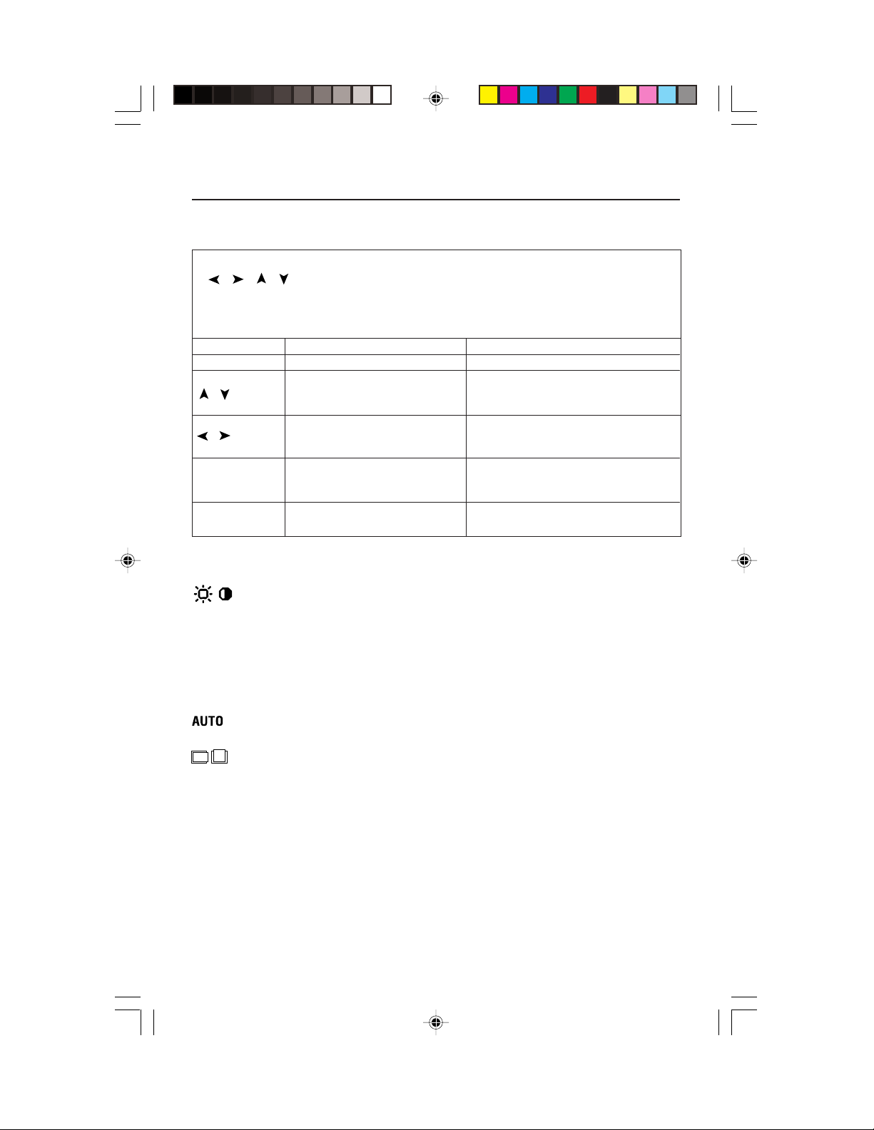
To access OSM menu, press any of the control buttons ( , , , ).
To change signal input, press the INPUT 1/2 button.
Main Menu Sub-Menu
EXIT Exits the OSM controls. Exits to the OSM main
CONTROL / Moves the highlighted Moves the highlighted
area up/down to select area up/down to select
one of the controls. one of the controls.
CONTROL / Moves the highlighted area Moves the bar left/
left/right to select control right to increase or
menus. decrease the adjustment.
PROCEED Has no function Activates Auto Adjust feature.
Push PROCEED to activate In Tools and Information
Auto Adjust. Mode, opens additional
RESET Resets the highlighted Resets the highlighted
control menu to the factory control to the factory
setting. setting.
menu.
window.
NOTE: When RESET is pressed in the main and sub-menu, a warning window
allowing you to cancel the RESET function by pressing the EXIT button.
Brightness/Contrast Controls
BRIGHTNESS
Adjusts the overall image and background screen brightness.
CONTRAST
Adjusts the image brightness in relation to the background.
AUTO ADJUST
Adjusts the image displayed for non-standard video inputs.
Auto Adjust
Automatically adjusts the Image Position and H. Size settings and Fine settings.
Position Controls
LEFT / RIGHT
Controls Horizontal Image Position within the display area of the LCD.
DOWN / UP
Controls Vertical Image Position within the display area of the LCD.
AUTO ADJUST
Automatically sets the Horizontal and Vertical Image Position within the
display area of the LCD.
7
will appear
LCD1830.wpc 11/29/00, 9:56 AM9
Page 10
Controls –continued
Image Adjust Controls
H.SIZE
Adjusts the horizontal size by increasing or decreasing this setting.
FINE
Improves focus, clarity and image stability by increasing or decreasing this setting.
AUTO ADJUST
Automatically adjusts H. SIZE and FINE settings.
AccuColor® Control Systems
Six color presets select the desired color setting (two of the color presets are
standard and cannot be changed). Color temperature increases or decreases
in each preset. R,Y,G,C,B,M,S: Increases or decreases Red, Yellow, Green,
Cyan, Blue, Magenta and Saturation depending upon which is selected. The
change in color will appear on screen and the direction (increase or decrease)
will be shown by the color bars.
Tools 1
SMOOTHING: Select one of three image sharpness settings. This function is
only valid when the expanded display function (expansion function)is on.
TEXT MODE: Use this to display text clearly.
NORMAL MODE: This sharpness is between TEXT and GRAPHIC MODE.
GRAPHIC MODE: This mode is suited for images and photographs.
EXPANSION MODE: Sets the zoom method.
FULL SCREEN: The image is expanded to 1280 x 1024, regardless of the resolution.
KEEP ASPECT: The image is expanded without changing the aspect ratio.
EXPANSION OFF: The image is not expanded.
VIDEO DETECT: Selects the method of video detection when more than one
computer is connected.
NONE: The Monitor will not search the other video input port unless the
monitor is turned on.
FIRST DETECT: The video input has to be switched to “FIRST DETECT”
mode. When current video input signal is not present, then the monitor
searches for a video signal from the other video input port. If the video
signal is present in the other port, then the monitor switches the video
source input port to the new found video source automatically. The
monitor will not look for other video signals while the current video
source is present.
LAST DETECT:
mode.
and a new secondary source is supplied to the monitor, then the monitor
will automatically switch to the new video source. When current video
input signal is not present, then the monitor searches for a video signal
from the other video input port. If the video signal is present in the other
port, then the monitor switches the video source input port to the new
found video source automatically.
The video input has to be switched to the “LAST DETECT”
When the monitor is displaying a signal from the current source
8
LCD1830.wpc 11/29/00, 9:56 AM10
Page 11
Controls –continued
Tools 2
LANGUAGE: OSM™ control menus are available in seven languages.
OSM POSITION: You can choose where you would like the OSM control
image to appear on your screen. Selecting OSM Location allows you to
manually adjust the position of the OSM control menu left, right, up or down.
OSM TURN OFF: The OSM control menu will stay on as long as it is use. In the
OSM Turn Off submenu, you can select how long the monitor waits after the
last touch of a button to shut off the OSM control menu. The preset chocies are
10, 20, 30, 60 and 120 seconds.
OSM LOCK OUT: This control completely locks out access to all OSM control
functions. When attempting to activate OSM controls while in the Lock Out
mode, a screen will appear indicating the OSM controls are locked out. To
activate the OSM Lock Out function, press PROCEED, then and hold down
simultaneously. To de-activate the OSM Lock Out, press PROCEED, then
and hold down simultaneously.
FACTORY PRESET: Selecting Factory Preset allows you to reset all OSM control
settings back to the factory settings. The RESET button will need to be held
down for several seconds to take effect. Individual settings can be reset by
highlighting the control to be reset and pressing the RESET button.
RESOLUTION NOTIFIER: This optimal resolution is 1280 x 1024. If ON is
selected, a message will appear on the screen after 30 seconds, notifying you
that the resolution is not at 1280 x 1024.
Information
DISPLAY MODE: Provides information about the current resolution display and
technical data including the preset timing being used and the horizontal and
vertical frequencies.
MONITOR INFO: Indicates the model and serial numbers of your monitor.
OSM™ Warning: OSM Warning menus disappear with Exit button.
NO SIGNAL: This function gives a warning when there is no signal present.
After power is turned on or when there is a change of input signal or video
is inactive, the No Signal window will appear.
RESOLUTION NOTIFIER: This function gives a warning of use with optimized resolution. After power is turned on or when there is a change of
input signal or the video signal doesn’t have proper resolution, the
Resolution Notifier window will open. This function can be disabled in
the TOOL menu.
OUT OF RANGE: This function gives a recommendation of the optimized
resolution and refresh rate. After the power is turned on or there is a
change of input signal or the video signal doesn’t have proper timing, the
Out Of Range menu will appear.
CHECK CABLE: This function will advise you to check all Video Inputs on the
monitor and computer to make sure they are properly connected.
LCD1830.wpc 11/29/00, 9:56 AM11
9
Page 12

Recommended Use
Safety Precautions and Maintenance
FOR OPTIMUM PERFORMANCE, PLEASE NOTE THE
FOLLOWING WHEN SETTING UP AND USING
THE MULTISYNC® LCD COLOR MONITOR:
• DO NOT OPEN THE MONITOR. There are no user serviceable parts inside and
opening or removing covers may expose you to dangerous shock hazards or other
risks. Refer all servicing to qualified service personnel.
• Do not spill any liquids into the cabinet or use your monitor near water.
• Do not insert objects of any kind into the cabinet slots, as they may touch dangerous
voltage points, which can be harmful or fatal or may cause electric shock, fire or
equipment failure.
• Do not place any heavy objects on the power cord. Damage to the cord may cause
shock or fire.
• Do not place this product on a sloping or unstable cart, stand or table, as the monitor
may fall, causing serious damage to the monitor.
• When operating the MultiSync LCD monitor with its AC 220-240V power supply, use a
power supply cord that matches the power supply voltage of the AC power outlet being
used. The power supply cord you use must have been approved by and comply with
the safety standards of your country. (Type H05VV-F should be used in Europe)
• In UK, use a BS-approved power cord with molded plug having a black (5A) fuse installed
for use with this monitor. If a power cord is not supplied with this monitor, please contact
your supplier.
• Do not place any objects onto the monitor and do not use the monitor outdoors.
• The inside of the flourescent tube located within the LCD monitor contains mercury.
Please follow the bylaws or rules of your municipality to dispose of the tube properly.
Immediately unplug your monitor from the wall outlet and refer servicing to qualified service
personnel under the following conditions:
• When the power supply cord or plug is damaged.
• If liquid has been spilled, or objects have fallen into the monitor.
• If the monitor has been exposed to rain or water.
• If the monitor has been dropped or the cabinet damaged.
• If the monitor does not operate normally by following operating instructions.
• Do not bend power cord.
• Do not use monitor in high temperatured, humid, dusty, or oily areas.
• If glass is broken, handle with care.
• Do not cover vent on monitor.
• If monitor or glass is broken, do not come in contact with the liquid crystal and handle
with care.
• Allow adequate ventilation around the monitor so that heat can properly
dissipate. Do not block ventilated openings or place the monitor near a
radiator or other heat sources. Do not put anything on top of monitor.
• The power cable connector is the primary means of detaching the system
CAUTION
from the power supply. The monitor should be installed close to a power
outlet which is easily accessible.
• Handle with care when transporting. Save packaging for transporting.
10
LCD1830.wpc 11/29/00, 9:56 AM12
Page 13
Recommended Use –continued
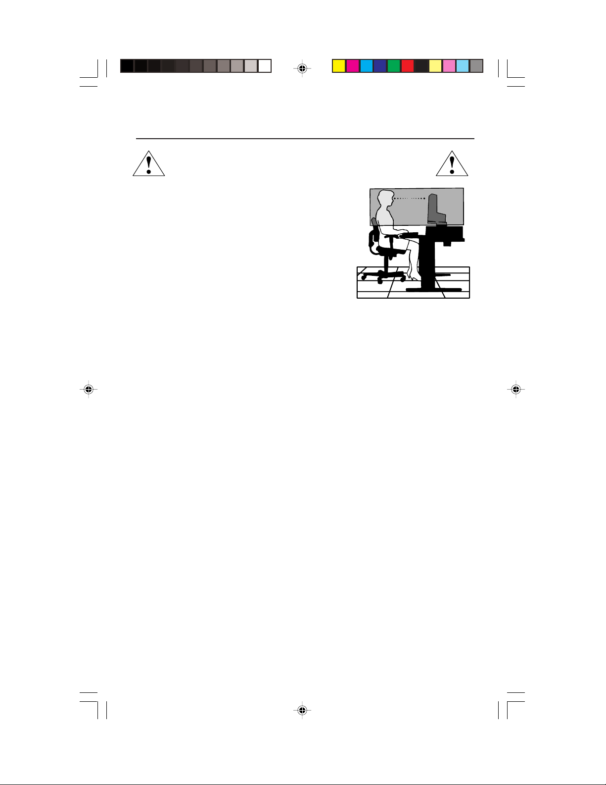
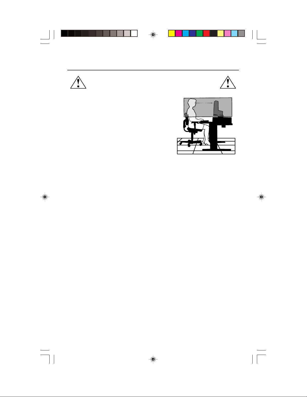
CORRECT PLACEMENT AND ADJUSTMENT OF THE MONITOR
CAN REDUCE EYE, SHOULDER AND NECK FATIGUE. CHECK THE
FOLLOWING WHEN YOU POSITION THE MONITOR:
• For optimum performance, allow 20 minutes for
warm-up.
• Adjust the monitor height so that the top of the
screen is at or slightly below eye level. Your eyes
should look slightly downward when viewing the
middle of the screen.
•
Position your monitor no closer than 16 inches
and no further away than 28 inches from your
eyes. The optimal distance is 20 inches.
• Rest your eyes periodically by focusing on an
object at least 20 feet away. Blink often.
• Position the monitor at a 90° angle to windows and other light sources to
minimize glare and reflections. Adjust the monitor tilt so that ceiling lights do
not reflect on your screen.
• If reflected light makes it hard for you to see your screen, use an anti-glare filter.
• Clean the LCD monitor surface with a lint-free, non-abrasive cloth. Avoid using
any cleaning solution or glass cleaner!
• Adjust the monitor’s brightness and contrast controls to enhance readability.
• Use a document holder placed close to the screen.
• Position whatever you are looking at most of the time (the screen or
reference material) directly in front of you to minimize turning your head
while you are typing.
• Avoid displaying fixed patterns on the monitor for long periods of time to avoid
image persistence (after-image effects).
• Get regular eye checkups.
Ergonomics
To realize the maximum ergonomics benefits, we recommend the following:
•
Adjust the Brightness until the background raster disappears
•
Do not position the Contrast control to its maximum setting
•
Use the preset Size and Position controls with standard signals
•
Use the preset Color Setting
•
Use non-interlaced signals with a vertical refresh rate between 60-75Hz
•
Do not use primary color blue on a dark background, as it is difficult to see and
may produce eye fatigue to insufficient contrast
For more detailed information on setting up a healthy work environment, call NEC
at (800) 820-1230, NEC FastFacts
document #900108 or write the American National Standard for Human Factors
Engineering of Visual Display Terminal Workstations – ANSI-HFS Standard
No. 100-1988 – The Human Factors Society, Inc. P.O. Box 1369, Santa Monica,
California 90406.
™
information at (800) 366-0476 and request
11
LCD1830.wpc 11/29/00, 9:56 AM13
Page 14
Specifications
Monitor MultiSync® LCD1830
™
Notes
Specifications Monitor
LCD Module Diagonal: 18.1 inch Active matrix; thin film transistor (TFT)
Input Signal Video: ANALOG 0.7 Vp-p/75 Ohms
Display Colors Analog input: 16,777,216 Depends on display card used.
Viewing Angle Left/Right: ± 80°
Synchronization Horizontal: 24 kHz to 82 kHz Automatically
Range Vertical: 55 Hz to 85 Hz Automatically
Resolutions Supported 720 x 400*
Resolution based on
vertical frequencies only
Active Display Area Horizontal:
Power Supply
Current Rating 0.8 A @ 100
Dimensions
Weight 8.5 kg
Environmental Considerations
Viewable Image Size: 18.1 inch liquid crystal display (LCD); 0.28 mm dot
Native Resolution (Pixel Count): 1280x1024 pitch; 200cd/m
Sync: Separate sync. TTL Level
Horizontal sync. Positive/Negative
Vertical sync. Positive/Negative
Composite sync. Positive/Negative
Sync on Green (Video 0.7p-p and Sync 0.3V p-p)
Up/Down: ± 80°
1
horizontal and
Vertical:
Operating Temperature: 5°C to 35°C/41°F to 95°F
Humidity: 30% to 80%
Storage Temperature: -10°C to 60°C/-14°F to 140°F
Humidity: 10% to 90%
640 x 480*1 at 60 Hz to 85 Hz
800 x 600*1 at 56 Hz to 85 Hz
832 x 624*
1024 x 768*
1152 x 864*
1152 x 900*
1280 x 960*1*2 at 60Hz to 75Hz
1280 x 1024
359 mm/14.1 inches Dependent upon signal timing used,
287 mm/11.3 inches and does not include border area.
AC 100 - 120V
435 mm (W) x 449 mm (H) x 215 mm (D)
17.1 inches (W) x 17.7 inches (H) x 8.5 inches (D)
18.7 lbs
Feet: 0 to 12,000 Feet
Feet: 0 to 53,300 Feet
at 70 Hz
1
at 75 Hz
1
at 60 Hz to 85 Hz
1
at 75Hz
1*2
at 66Hz
at 60 Hz to 76 Hz .................
/220–240 V
–
120 V, 0.4 A @ 220-240 V
@ 50/60 Hz
300:1 contrast ratio, typical
Some systems may not support
all modes listed.
NEC-Mitsubishi Electronics Display cites
recommended resolution at 60 Hz for
optimal display performance.
2
white luminence;
1
*
Interpolated Resolutions: When resolutions are shown that are lower than the pixel count of the LCD module, text may
appear different. This is normal and necessary for all current flat panel technologies when displaying non-native
resolutions full screen. In flat panel technologies, each dot on the screen is actually one pixel, so to expand resolutions to
full screen, an interpolation of the resolution must be done.
2
*
The number of colors displayed that can be decreased.
NOTE: Technical specifications are subject to change without notice.
12
LCD1830.wpc 11/29/00, 9:56 AM14
Page 15

Features
Reduced Footprint: Provides the ideal solution for environments requiring superior image
quality but with size and weight limitations. The monitor’s small footprint and low weight
allow it to be moved or transported easily from one location to another.
AccuColor® Control Systems: Six color presets select the desired color setting (sRGB and
NATIVE color presets are standard and cannot be changed). Color temperature increases
or decreases, in each preset. R,Y,G,C,B,M,S: Increases or decreases Red, Yellow, Green,
Cyan, Blue, Magenta and Saturation depending upon which is selected. The change in
color will appear on screen and the direction (increase or decrease) will be shown by the
color bars. NATIVE:
sRGB: sRGB mode dramatically improves the color fidelity in the desktop environment by a
single standard RGB color space. With this color supported environment, the operator
could easily and confidently communicate color without further color management
overhead in the most common situations. In this mode the brightness and contrast controls
are frozen to insure full color capability.
™
OSM
(On-Screen Manager) Controls: Allow you to quickly and easily adjust all elements
of your screen image via simple to use on-screen menus.
ErgoDesign
®
Features: Enhance human ergonomics to improve the working environment,
protect the health of the user and save money. Examples include
and easy image adjustments, tilt base for preferred angle of vision, small footprint and
compliance with MPRII and TCO guidelines for lower emissions
Plug and Play: The Microsoft
facilitates setup and installation by allowing
capabilities (such as screen size and resolutions supported)
computer, automatically optimizing display performance.
Original color presented by the LCD panel that is unadjustable.
OSM controls for quick
.
®
solution with the Windows®95/98 operating system
the monitor to send its
directly to your
IPM™ (Intelligent Power Manager) System: Provides innovative power-saving methods
that allow the monitor to shift to a lower power consumption level when on but not in use,
saving two-thirds of your monitor energy costs, reducing emissions and lowering the air
conditioning costs of the workplace.
Multiple Frequency Technology: Automatically adjusts monitor to the display card’s
scanning frequency, thus displaying the resolution required.
FullScan
™
Capability: Allows you to use the entire screen area in most resolutions,
significantly expanding image size.
XtraView
®
Wide Viewing Angle Technology: Allows the user to be able to see the monitor
from any angle (160 degrees) from any orientation — Portrait or Landscape. Provides full
160° viewing angles either up, down, left or right.
VESA Standard Mounting Interface: Allows users to connect their MultiSync monitor to
any VESA standard third party mounting arm or bracket. Allows for the monitor to be
mounted on a wall or an arm using any third party compliant device.
OSM Display Screen Copyright 2000 by
NEC-Mitsubishi Electronics Display of America, Inc.
13
LCD1830.wpc 11/29/00, 9:56 AM15
Page 16

Troubleshooting
No picture
•
The signal cable should be completely connected to the display card/computer.
• The display card should be completely seated in its slot.
• Power Switch and computer power switch should be in the ON position.
•
Check to make sure that a supported mode has been selected on the display card or system
being used. (Please consult display card or system manual to change graphics mode.)
• Check the monitor and your display card with respect to compatibility and recommended settings.
• Check the signal cable connector for bent or pushed-in pins.
• Check the signal input, “INPUT 1” or “INPUT 2”.
Image persistence
• Image persistence is when a “ghost” of an image remains on the screen even after the
monitor has been turned off. Unlike CRT monitors, LCD monitors’ image persistence is
not permanent. To alleviate image persistence, turn the monitor off for as long as an
image was displayed. If an image was on the monitor for one hour and a ”ghost” of
that image remains, the monitor should be turned off for one hour to erase the image.
NOTE: As with all personal display devices, NEC-Mitsubishi Electronics Display of America
recommends using a screen saver at regular intervals whenever the screen is idle.
Image is unstable, unfocused or swimming is apparent
• Signal cable should be completely attached to the computer.
• Use the OSM Image Adjust controls to focus and adjust display by
increasing or decreasing the fine total. When the display mode is changed, the OSM
Image Adjust settings may need to be re-adjusted.
• Check the monitor and your display card with respect to compatibility
and recommended signal timings.
•
If your text is garbled, change the video mode to non-interlace and use 60Hz refresh rate.
LED on monitor is not lit
• Power Switch should be in the ON position and power cord should be connected.
• Make certain the computer is not in a power-saving mode (touch the
keyboard or mouse).
Display image is not sized properly
• Use the OSM Image Adjust controls to increase or decrease the Coarse total.
•
Check to make sure that a supported mode has been selected on the display card or system
being used. (Please consult display card or system manual to change graphics mode.)
No Video
• If no vieo is present on the screen, turn the Power button off and on again.
(no green or amber color can be seen)
LCD1830.wpc 11/29/00, 9:56 AM16
14
Page 17

References
• BBS (978) 742-8706
NEC-Mitsubishi Electronics Display of America Remote Bulletin Board System is
an electronic service accessible with your system and a modem. Communication parameters are: 300/1200/2400/9600/14.4k/28.8k/33.6k bps, no
parity, 8-data bits, 1 stop bit
• Customer Service/
Technical Support (800) 632-4662
Fax (978) 742-7049
• Electronic Channels:
Internet e-mail: tech-support@necmitsubishi.com
Internet ftp site: ftp.necmitsubishi.com
World Wide Web: http://www.necmitsubishi.com
Product Registration:
European Operations: http://www.nec-monitors.com
Windows® 95/98/2000 INF File:
• FastFacts™ Information (800) 366-0476
INFORMATION DESCRIPTION DOCUMENT #
Glossary Definition of terms related 900203
More Information Names and addresses of 900204
Macintosh Connection Detailed information on 153006
Healthy Work Environment Detailed information on 900108
• Literature & Sales Info (800) NEC-INFO [(800) 632-4636]
• MultiSync Fulfillment (800) 820-1230
• TeleSales (800) 284-4484
http://www.necmitsubishi.com/productregistration
http://support.necmitsubishi.com/software.htm
then download the file NECMSINF.ZIP
to functions, features and
installation of the
MultiSync® monitor
other groups involved in
standards and features of
the MultiSync monitor
connecting the MultiSync
monitor to a Macintosh
setting up a healthy work
environment
[For software & accessories]
LCD1830.wpc 11/29/00, 9:56 AM17
15
Page 18

Limited Warranty
NEC-Mitsubishi Electronics Display of America, Inc. (hereinafter “NMD-A”) warrants this
Product to be free from defects in material and workmanship and, subject to the conditions set
forth below, agrees to repair or replace (at NMD-A’s sole option) any part of the enclosed unit
which proves defective for a period of three (3) years from the date of first consumer purchase.
Spare parts are warranted for ninety (90) days. Replacement parts or unit may be new or
refurbished and will meet specifications of the original parts or unit.
This warranty gives you specific legal rights and you may also have other rights, which vary
from state to state. This warranty is limited to the original purchaser of the Product and is not
transferable. This warranty covers only NMD-A-supplied components. Service required as a
result of third party components is not covered under this warranty. In order to be covered
under this warranty, the Product must have been purchased in the U.S.A. or Canada by the
original purchaser. This warranty only covers Product distribution in the U.S.A. or Canada by
NMD-A No warranty service is provided outside of the U.S.A. or Canada. Proof of Purchase
will be required by NMD-A to substantiate date of purchase. Such proof of purchase must be
an original bill of sale or receipt containing name and address of seller, purchaser, and the
serial number of the product.
It shall be your obligation and expense to have the Product shipped, freight prepaid, or
delivered to the authorized reseller from whom it was purchased or other facility authorized
by NMD-A to render the services provided hereunder in either the original package or a
similar package affording an equal degree of protection. All Products returned to NMD-A for
service MUST have prior approval, which may be obtained by calling 1-800-632-4662. The
Product shall not have been previously altered, repaired, or serviced by anyone other than a
service facility authorized by NMD-A to render such service, the serial number of the product
shall not have been altered or removed. In order to be covered by this warranty the Product
shall not have been subjected to displaying of fixed images for long periods of time resulting
in image persistence (afterimage effects), accident, misuse or abuse or operated contrary to
the instructions contained in the User’s Manual. Any such conditions will void this warranty.
NMD-A SHALL NOT BE LIABLE FOR DIRECT, INDIRECT, INCIDENTAL, CONSEQUENTIAL,
OR OTHER TYPES OF DAMAGES RESULTING FROM THE USE OF ANY NMD-A PRODUCT
OTHER THAN THE LIABILITY STATED ABOVE. THESE WARRANTIES ARE IN LIEU OF ALL
OTHER WARRANTIES EXPRESS OR IMPLIED, INCLUDING, BUT NOT LIMITED TO, THE
IMPLIED WARRANTIES OF MERCHANTABILITY OR FITNESS FOR A PARTICULAR PURPOSE.
SOME STATES DO NOT ALLOW THE EXCLUSION OF IMPLIED WARRANTIES OR THE
LIMITATION OR EXCLUSION OF LIABILITY FOR INCIDENTAL OR CONSEQUENTIAL DAMAGES SO THE ABOVE EXCLUSIONS OR LIMITATIONS MAY NOT APPLY TO YOU.
This Product is warranted in accordance with the terms of this limited warranty. Consumers
are cautioned that Product performance is affected by system configuration, software, the
application, customer data, and operator control of the system, among other factors. While
NMD-A Products are considered to be compatible with many systems, specific functional
implementation by the customers of the Product may vary. Therefore, suitability of a Product
for a specific purpose or application must be determined by consumer and is not warranted
by NMD-A.
For the name of your nearest authorized NEC-Mitsubishi Electronics Display service facility,
contact NEC-Mitsubishi Electronics Display of America at 1-800-632-4662.
LCD1830.wpc 11/29/00, 9:56 AM18
16
Page 19

TCO’95
MultiSync LCD1830 Black Model (LA-18S02-BK)
Congratulations! You have just purchased a TCO’95 approved and
labeled product! Your choice has provided you with a product developed
for professional use. Your purchase has also contributed to reducing the
burden on the environment and also, to the further development of
environmentally adapted electronics products.
Why do we have environmentally labelled computers?
In many countries, environmental labelling has become an established method for encouraging the adaptation of goods and services to the environment. The main problem, as far as
computers and other electronics equipment are concerned, is that environmentally harmful
substances are used both in the products and during the manufacturing. Since it has not been
possible for the majority of electronics equipment to be recycled in a satisfactory way, most
of these potentially damaging substances sooner or later enter Nature.
There are also other characteristics of a computer, such as energy consumption levels, that are
important from the viewpoints of both the work (Internal) and natural (external) environments.
Since all methods of conventional electricity generation have a negative effect on the
environment (acidic and climate-influencing emissions, radioactive waste, etc.), it is vital to
conserve energy. Electronics equipment in offices consume an enormous amount of energy
since they are often left running continuously.
What does labelling involve?
This product meets the requirements for the TCO’95 scheme which provides for international
and environmental labelling of personal computers. The labelling scheme was developed as
a joint effort by the TCO (The Swedish Confederation of Professional Employees),
Naturskyddsforeningen (The Swedish Society for Nature Conservation) and NUTEK (The
National Board for Industrial and Technical Development in Sweden).
The requirements cover a wide range of issues: environment, ergonomics, usability, emission
of electrical and magnetic fields, energy consumption and electrical and fire safety.
The environmental demands concern restrictions on the presence and use of heavy metals,
brominated and chlorinated flame retardants, CFCs (freons) and chlorinated solvents, among
other things. The product must be prepared for recycling and the manufacturer is obliged to
have an environmental plan which must be adhered to in each country where the company
implements its operational policy. The energy requirements include a demand that the
computer and/or display, after a certain period of inactivity, shall reduce its power
consumption to a lower level in one or more stages. The length of time to reactivate the
computer shall be reasonable for the user.
Labelled products must meet strict environmental demands, for example, in respect of the
reduction of electric and magnetic fields, physical and visual ergonomics and good usability.
TCO’95 is a co-operative project between TCO (The Swedish Confederation of Professional
Employees), Naturskyddsforeningen (The Swedish Society for Nature Conservation) and
NUTEK (The National Board for Industrial and Technical Development in Sweden).
Environmental Requirements
Brominated flame retardants
Brominated flame retardants are present in printed circuit boards, cables, wires, casings and
housings. In turn, they delay the spread of fire. Up to thirty percent of the plastic in a computer
casing can consist of flame retardant substances. These are related to another group of
environmental toxins, PCBs, which are suspected to give rise to similar harm, including
LCD1830.wpc 11/29/00, 9:56 AM19
17
Page 20

TCO’95 –continued
reproductive damage in fisheating birds and mammals, due to the bio-accumulative*
processes. Flame retardants have been found in human blood and researchers fear that
disturbances in foetus development may occur.
TCO’95 demand requires that plastic components weighing more than 25 grams must not
contain organically bound chlorine and bromine.
Lead**
Lead can be found in picture tubes, display screens, solders and capacitors. Lead damages
the nervous system and in higher doses, causes lead poisoning.
TCO’95 requirement permits the inclusion of lead since no replacement has yet been
developed.
Cadmium**
Cadmium is present in rechargeable batteries and in the colourgenerating layers of certain
computer displays. Cadmium damages the nervous system and is toxic in high doses.
TCO’95 requirement states that batteries may not contain more than 25 ppm (parts per million)
of cadmium. The colourgenerating layers of display screens must not contain any cadmium.
Mercury**
Mercury is sometimes found in batteries, relays, switches, and back-light systems, Mercury
damages the nervous system and is toxic in high doses.
TCO’95 requirement states that batteries may not contain more than 25 ppm (parts per million)
of mercury. It also demands that no mercury is present in any of the electrical or electronics
components concerned with the display unit, except the back-light system.
CFCs (freons)
CFCs (freons) are sometimes used for washing printed circuit boards and in the manufacturing
of expanded foam for packaging. CFCs break down ozone and thereby damage the ozone
layer in the stratosphere, causing increased reception on Earth of ultraviolet light with
consequent increased risks of skin cancer (malignant melanoma).
The relevant TCO’95 requirement; Neither CFCs nor HCFCs may be used during the
manufacturing of the product or its packaging.
*Bio-accumulative is defined as substances which accumulate within living organisms.
**Lead, Cadmium and Mercury are heavy metals which are Bio-accumulative.
To obtain complete information on the environmental criteria document, order from:
TCO Development Unit
SE-114 94 Stockholm
SWEDEN
FAX Number: +46 8 782 92 07
E-mail (Internet): development@tco.se
You may also obtain current information on TCO’95 approved and labelled products
by visiting their website at: http://www.tco-info.com/
LCD1830.wpc 11/29/00, 9:56 AM20
18
Page 21
TCO’99
MultiSync LCD1830 White Model (LA-18S02)
Congratulations! You have just purchased a TCO’99 approved and
labeled product! Your choice has provided you with a product developed for professional use. Your purchase has also contributed to
reducing the burden on the environment and also to the further
development of environmentally adapted electronics products.
Why do we have environmentally labelled computers?
In many countries, environmental labelling has become an established method for encouraging the adaptation of goods and services to the environment. The main problem, as far as
computers and other electronics equipment are concerned, is that environmentally harmful
substances are used both in the products and during the manufacturing. Since it has not been
possible for the majority of electronics equipment to be recycled in a satisfactory way, most
of these potentially damaging substances sooner or later enter Nature.
There are also other characteristics of a computer, such as energy consumption levels, that are
important from the viewpoints of both the work (Internal) and natural (external) environments.
Since all methods of conventional electricity generation have a negative effect on the
environment (acidic and climate-influencing emissions, radioactive waste, etc.), it is vital to
conserve energy. Electronics equipment in offices consume an enormous amount of energy
since they are often left running continuously.
What does labelling involve?
This product meets the requirements for the TCO’99 scheme which provides for international and
environmental labelling of personal computers. The labelling scheme was developed as a joint
effort by the TCO (The Swedish Confederation of Professional Employees), Svenska
Naturskyddsforeningen (The Swedish Society for Nature Conservation) and Statens Energimyndighet
(The Swedish National Energy Administration).
The requirements cover a wide range of issues: environment, ergonomics, usability, emission of
electrical and magnetic fields, energy consumption and electrical and fire safety.
The environmental demands concern restrictions on the presence and use of heavy metals,
brominated and chlorinated flame retardants, CFCs (freons) and chlorinated solvents, among other
things. The product must be prepared for recycling and the manufacturer is obliged to have an
environmental plan which must be adhered to in each country where the company implements its
operational policy. The energy requirements include a demand that the computer and/or display,
after a certain period of inactivity, shall reduce its power consumption to a lower level in one or
more stages. The length of time to reactivate the computer shall be reasonable for the user.
Labelled products must meet strict environmental demands, for example, in respect of the reduction
of electric and magnetic fields, physical and visual ergonomics and good usability.
Environmental Requirements
Flame retardants
Flame retardants are present in printed circuit boards, cables, wires, casings and housings. In turn,
they delay the spread of fire. Up to thirty percent of the plastic in a computer casing can consist of
flame retardant substances. Most flame retardants contain bromine or chloride and these are
related to another group of environmental toxins, PCBs, which are suspected to give rise to severe
health effects, including reproductive damage in fisheating birds and mammals, due to the bio-
19
LCD1830.wpc 11/29/00, 9:56 AM21
Page 22

TCO’99 –continued
accumulative* processes. Flame retardants have been found in human blood and researchers fear
that disturbances in foetus development may occur.
TCO’99 demand requires that plastic components weighing more than 25 grams must not contain
flame retardants with organically bound chlorine and bromine. Flame retardants are allowed in
the printed circuit boards since no substitutes are available.
Lead**
Lead can be found in picture tubes, display screens, solders and capacitors. Lead damages the
nervous system and in higher doses, causes lead poisoning.
TCO’99 requirement permits the inclusion of lead since no replacement has yet been developed.
Cadmium**
Cadmium is present in rechargeable batteries and in the colourgenerating layers of certain
computer displays. Cadmium damages the nervous system and is toxic in high doses.
TCO’99 requirement states that batteries, the colourgenerating layers of display screens and the
electrical or electronics components must not contain any cadmium.
Mercury**
Mercury is sometimes found in batteries, relays and switches, Mercury damages the nervous system
and is toxic in high doses.
TCO’99 requirement states that batteries may not contain any Mercury. It also demands that no
mercury is present in any of the electrical or electronics components associated with the display unit.
CFCs (freons)
CFCs (freons) are sometimes used for washing printed circuit boards. CFCs break down ozone and
thereby damage the ozone layer in the stratosphere, causing increased reception on Earth of
ultraviolet light with consequent increased risks of skin cancer (malignant melanoma).
The relevant TCO’99 requirement; Neither CFCs nor HCFCs may be used during the manufacturing
and assembly of the product or its packaging.
*Bio-accumulative is defined as substances which accumulate within living organisms.
**Lead, Cadmium and Mercury are heavy metals which are Bio-accumulative.
To obtain complete information on the environmental criteria document, order from:
TCO Development Unit
SE-114 94 Stockholm
SWEDEN
FAX Number: +46 8 782 92 07
E-mail (Internet): development@tco.se
You may also obtain current information on TCO’99 approved and labelled products by
visiting their website at: http://www.tco-info.com/
20
LCD1830.wpc 11/29/00, 9:56 AM22
Page 23

Declaration of the Manufacturer
We hereby certify that the color monitor
MultiSync® LCD1830TM (LA-18S02) and
MultiSync® LCD1830TM (LA-18S02-BK)
are in compliance with
Council Directive 73/23/EEC:
– EN 60950
Council Directive 89/336/EEC:
– EN 55022
– EN 61000-3-2
– EN 61000-3-3
– EN 55024
(IEC 61000-4-2)
(IEC 61000-4-3)
(IEC 61000-4-4)
(IEC 61000-4-5)
(IEC 61000-4-6)
(IEC 61000-4-8)
(IEC 61000-4-11)
and marked with
NEC-Mitsubishi Electric Visual
Kanagawa 258-8533, Japan
LCD1830.wpc 11/29/00, 9:56 AM23
Systems Corporation
686-1, Nishioi Oi-Machi
Ashigarakami-gun
21
Page 24

Notes
LCD1830.wpc 11/29/00, 9:56 AM24
22
Page 25

AVERTISSEMENT
AFIN D’ÉVITER TOUT RISQUE D’INCENDIE OU D’ÉLECTROCUTION, NE PAS EXPOSER CET APPAREIL À LA PLUIE OU À
L’HUMIDITÉ. NE PAS UTILISER LA FICHE D’ALIMENTATION POLARISÉE AVEC UNE PRISE DE CORDON DE RALLONGE
OU AUTRE PRISE SAUF SI LES BROCHES PEUVENT ÊTRE ENTIÈREMENT INTRODUITES.
NE PAS OUVRIR LE BOÎTIER, LEQUEL CONTIENT DES COMPOSANTS À HAUTE TENSION. CONFIER TOUS TRAVAUX
À DU PERSONNEL TECHNIQUE QUALIFIÉ.
ATTENTION
RISQUE DE DÉCHARGE ÉLECTRIQUE • NE PAS OUVRIR
ATTENTION : POUR ÉVITER TOUT RISQUE D'ÉLECTROCUTION, NE PAS OUVRIR LE COUVERCLE (L'ARRIÈRE). À L'INTÉRIEUR, AUCUNE
PIÈCE NE NÉCESSITE L'INTERVENTION DE L'UTILISATEUR. EN CAS DE PROBLÈME, S'ADRESSER À DU PERSONNEL TECHNIQUE QUALIFIÉ.
Ce symbole est une mise en garde contre les risques d'électrocution que présentent certaines parties dépourvues
d'isolation à l'intérieur de l'appareil. Il est donc dangereux d'établir le moindre contact avec ces parties
Ce symbole prévient l'utilisateur que des directives d'utilisation et de maintenance de cet appareil sont fournies avec
ce guide d’utilisateur. Par conséquent, celles-ci doivent être lues attentivement pour éviter tout incident.
.
Déclaration de conformité – Département des Communications du Canada
DOC : Cet appareil numérique de classe B respecte toutes les exigences du Règlement
sur le matériel à l'origine d'interférences du Canada.
C-UL : Ce produit porte la marque «C-UL» et est conforme aux règlements de sécurité
canadiens selon CAN/CSA C22.2 No. 950.
Informations FCC
1.
Utiliser les câbles spécifiés fournis avec les moniteur couleur MultiSync LCD
BK)
afin de ne pas provoquer d'interférences avec la réception radio et télévision
(1) Prière d'utiliser le câble d'alimentation fourni ou équivalent pour assurer la conformité FCC.
(2) Veuillez utiliser le câble de signal vidéo blindé fourni, un mini D-SUB à 15 broches vers le câble
un mini D-SUB à 15 broches.
2.
Cet appareil a été testé et s’avère conforme avec les spécifications d'équipements de Classe B, section 15
de la réglementation FCC. Ces spécifications ont été établies pour garantir une protection raisonnable
contre les interférences nuisibles dans une installation résidentielle. Cet appareil génère, utilise et peut
émettre des fréquences radio et, s'il n'est pas installé et utilisé selon les directives de ce guide, il peut
perturber les communications radio. Cependant, il n'est pas garanti qu'aucune interférence ne se produira
dans une installation donnée.
Si cet appareil provoque des interférences nuisibles à la réception radio ou télévision, ce que vous pouvez
déterminer en allumant et en éteignant l'appareil, essayez de remédier au problème en prenant une ou
plusieurs des mesures suivantes :
• Réorienter ou repositionner l'antenne de réception.
• Augmenter la distance entre l'appareil et le récepteur.
• Connecter l'appareil à une prise de courant sur un circuit différent de celui sur lequel le récepteur
est connecté.
• Consulter son revendeur ou un technicien radio/TV pour obtenir de l'aide.
Si nécessaire, l'utilisateur doit contacter le revendeur ou un technicien radio/TV afin d'obtenir des
informations supplémentaires. L'utilisateur peut se procurer le livret utile suivant, préparé par la Federal
Communications Commission : «How to Identify and Resolve Radio-TV Interference Problems» (Comment
cerner et résoudre les problèmes d’interférences radio/TV). Ce livret est disponible auprès du U.S.
Government Printing Office, Washington, D.C., 20402, Stock No. 004-000-00345-4.
1830
(LA-18S02 et LA-18S02-
.
LCD1830.wpc 11/29/00, 9:56 AM25
23
Page 26

Contenu
La boîte* de votre nouveau moniteur NEC MultiSync® contient :
• Moniteur MultiSync LCD1830
• Cordon d'alimentation
• Câble d’interface vidéo
• Manuel de l’utilisateur
MC
avec socle inclinable
USER'S MANUAL
MultiSync
LCD1830
To learn about other special offers, register online at www.necmitsubishi.com/productregistration
* Ne pas oublier de conserver la boîte et le matériel d'emballage d'origine pour transporter ou expédier le moniteur.
®
™
24
LCD1830.wpc 11/29/00, 9:56 AM26
Page 27
Mise en marche rapide
Pour raccorder le moniteur MultiSync® LCD1830MC au système,
suivez les directives ciaprès :
1. Mettez l’ordinateur hors tension.
2. PC : Branchez le mini-connecteur D-SUB à 15 broches du câble vidéo approprié dans
le connecteur de la carte vidéo de votre ordinateur (Figure A.1). Serrez toutes les vis.
Macintosh : Branchez l’adaptateur de câble Macintosh pour MultiSync LCD
dateur (Figure B.1). Branchez le du câble vidéo dans l’adaptateur de câble Macintosh
pour MultiSync LCD
NOTA :
Pour obtenir un adaptateur de câble Macintosh pour le MultiSync LCD
1830 (Figure B.1). Serrez toutes les vis.
appelez NEC-Mitsubishi Electronics Display of America, Inc. au (800) 820-1230.
3.
Relie la 15 épingle mini D SUB de la vidéo signale du câble au connecteur “INPUT 1”
OU “INPUT 2” sur arrière de l’écran
(Figure C.1).
NOTA : Une mauvaise connexion des câbles peut nuire au fonctionnement,
endommager l’affichage et nuire à la qualité de l’affichage du module LCD
et/ou réduire la durée de vie utile du module.
4.
Connectez une extrémité du câble d’alimentation sur l’adaptateur CA et l’autre extrémité
sur la prise de secteur (Figure C.1). Remplace connecteur étui et étui cable (Figure E.1).
NOTA: Si vous utilisez ce moniteur à AC220-240V, s'il vous plaît faites référence à
section de l'Usage Recommandée de ce manuel pour sélection adéquate d'AC
pouvoir cordon.
5. Mettez le moniteur (Figure D.1) et l’ordinateur sous tension.
6.
Pour conclure l’installation du moniteur MultiSync LCD
Utilisez les commandes OSM
MC
suivantes :
1830
:
• Contraste automatique
• Réglage automatique
Pour une description complète de ces commandes OSM, consultez la section
Commandes de ce guide.
NOTA : Pour des informations sur le téléchargement du fichier INF Windows® 95/98
pour le moniteur MultiSync, consultez la section Références de ce guide.
NOTA : En cas de problème, consultez la section Dépannage de ce manuel.
NOTA : Pour enlever plus facilement le couvercle du câble d’alimentation ou du câble
à
signal, retourner le moniteur (Figure R.2).
1830
1830
Figure A.1 Figure B.1
LCD1830.wpc 11/29/00, 9:56 AM27
15-pin
mini D-SUB
Adaptateur
Macintosh
(non foumi)
15-pin
mini
D-SUB
25
Page 28

Mise en marche rapide (suite)
Figure C.1
Cordon
d'alimentation
Câble
d’interface
vidéo
1. Des câbles passent dedans à travers de trou.
2. Relie connecteur chaque.
3. Remplace connecteur de l’étui sur câbles
passant à travers de upper ouvrant.
Power Outlet
LCD1830.wpc 11/29/00, 9:56 AM28
To Computer
Bouton d’alimentation
Figure D.1
26
INPUT2
INPUT1
AC-IN
Page 29
Mise en marche rapide (suite)
2
3
1
Marque
Partie marquée
(1.Appuyer)
Cache-câble
Pour enlever le cache-câble:
1. Appuyer sur la partie marquée
2. Faire glisser vers le haut
3. Enlever
2
LCD1830.wpc 11/29/00, 9:56 AM29
Appuyer
Figure E.1
27
1
Couvercle de connecteur
Pour enlever le couvercle :
1. Appuyer à la partie inférieure
2. Enlever
1
Appuyer
Page 30

Mise en marche rapide (suite)
Tilt
Poigne et côtés de l’écran filtre sur vos mains
et ajuste le tilt que désirai (Figure TS.1).
Remove Contrôle Représenter Montage
À préparer à d’alterner le montage des buts
l’écran pour:
1.
1. Le connecteur de
Remove couvre, que
charnière couvre et câble
de l’étui (Figure R.1).
2.
Déconnecte tout des câbles.
3.
L’écran place visage en bas
surface abrasive sur un non
(place l’écran sur une 32
estrade de mm
afin que trou de stand
s’assortit pour serrer de
l’emplacement) (Figure R.2).
4.
Remove 4 les vis reliant
l’écran
au stand et ascenseur off le
stand (Figure R.2) de
assembly l’écran est le montage
maintenant ready for dans
une manière alternative.
5.
Relie le AC du cordon au dos
de l’écran
6.
Ce procédé contraire à
.
reattach place.
32mm
Figure TS.1
PUSH
Figure R.1
Figure R.2
Screws
PUSH
Attention: Afin de satisfaire les consignes
de sécurité, le moniteur doit être
monté sur un bras assurant une
stabilité en fonction du poids du
moniteur. Le moniteur LCD ne
doit être utilisé qu’avec un bras
agréé
(ex. portant la marque GS)
LCD1830.wpc 11/29/00, 9:56 AM30
.
28
Page 31
Commandes
Les boutons de réglage OSMMC situés sur l’avant du moniteur fournissent
les fonctions suivantes :
Pour accéder au menu OSM, appuyez sur une des touches de commande
( , , , )
À transformer signale de l’entrée, presser le INPUT 1/2 bouton.
EXIT Quitte les commandes OSM. Retour au menu principal OSM.
CONTROL Déplace la zone en surbrillance vers Déplace la zone en surbrillance vers
/ le haut/le bas pour sélectionner une le haut/le bas pour sélectionner une
CONTROL Déplace la zone en surbrillance vers la Déplace la curseur vers la gauche/la droite
/ gauche/droite pour sélectionner pour augmenter la valeur du réglage.
PROCEED Pas de fonction.
RESET Rappel des paramètres usines du Rappel des paramètres usines de la
NOTA : En appuyant sur le bouton RESET dans un menu ou dans un sous-menu, une fenêtre s’affiche
vous permettant d’annuler la fonction RESET en appuyant sur le bouton EXIT.
Commandes de luminosité/contraste
Réglage automatique
Commandes de position
.
Menu principal Sous-menu
des commandes. des commandes.
une des commande.
De la poussée PROCEED
pour activer qu’Auto Ajuste.
menu des commandes en surbrillance. commande en surbrillance.
LUMINOSITÉ
Règle la luminosité de l'image générale et de l'écran d'arrière-plan.
CONTRASTE
Règle la luminosité de l'image par rapport à l'arrière-plan.
RÉGLAGE AUTO
Règle l’image affichée pour les modes vidéo non standard.
Règle automatiquement la position, le format horizontal ou la résolution fine.
GAUCHE/DROITE
Contrôle la position horizontale de l’image dans la zone d’affichage du LCD.
BAS/HAUT
Contrôle la position verticale de l’image dans la zone d’affichage du LCD.
RÉGLAGE AUTO
Corrige automatiquement la position horizontale et verticale dans la zone
d’affichage du LCD.
Verrouillez réglage automatique fonction. En mode
Outils et d’Information, ouvre, supplémentaire le
window.
LCD1830.wpc 11/29/00, 9:56 AM31
29
Page 32
Commandes (suite)
Réglage image
SIMPLE
Règle la dimension horizontale de l’image en augmentant ou en diminuant le
format horizontal.
FIN
Améliore la mise au point, la netteté et la stabilité de l’image en augmentant
ou en diminuant la valeur Fin.
RÉGLAGE AUTO
Ajuste automatiquement les réglages SIMPLE et FIN.
Système de contrôle des couleurs AccuColor
Six colore prérégle sélectionner la désiré couleur mettant (prérégle sommes
standards et deux de la couleur cannot être transformé). De la température Color
augmente préréglé ou chacun diminue
être diminué. R,Y,G,C,B,M,S: Augmentations ou diminutions Rouge, Jaune, Vert,
Cyan, Bleu, Magenta et Saturation dépendant sur qui est sélectionné. Le
changement dans couleur apparaîtra sur écran et la direction (augmentation ou
diminue) être transparu par la couleur des bars.
Outils I
LISSAGE : Sélectionnez une des trois réglages de netteté d’image.
Cette fonction et valide uniquement lorsque la fonction d’affichage agrandi
(fonction d’agrandissement) est activée.
MODE TEXTE : Utilisez ce réglage pour afficher clairement le texte.
MODE STANDARD : La netteté se situe entre MODE TEXTE et MODE GRAPHIQUE.
MODE GRAPHIQUE: Ce mode est destiné aux images et photos.
MODE ETENDU : Règle la méthode de zoom.
ECRAN COMPLET : L’image est agrandie à 1280 x 1024
indépendamment de la résolution.
MAINTENIR FORMAT : L’image est agrandie sans modification du taux d’aspect.
PAS D’EXTENSION : L’image n’est pas agrandie.
DETECTION VIDEO : Sélectionne la méthode de détection vidéo lorsque
plusieurs ordinateurs sont branchés em même temps.
PAS DE PRIORITE: Le moniteur ne scrute pas l’autre port d’entrée vidéo à
moins que le moniteur ne soit sous tension.
1ERE DETECTION :
En l’absence de signal de l’entrée vidéo courante, le moniteur cherche un
signal vidéo dans l’autre port d’entrée vidéo. Si le moniteur détecte un
signal vidéo dans l’autre port, il règle automatiquement le port d ’entrée
de la source vidéo sur la nouvelle source vidéo détectée. Le moniteur ne
cherche pas d’autres signaux vidéo tant que la source vidéo courante est active.
DERNIERE DETECTION : L’entrée vidéo doit être réglée sur le mode “DERNIERE
DETECTION”. Si
’une nouvelle source secondaire est activée, le moniteur se branche
automatiquement sur cette nouvelle source vidéo. En l’absence de signal de
l’entrée vidéo courante, le moniteur cherche un signal vidéo dans l’autre port
d’entrée vidéo. Si le signal vidéo est présent sur l’autre port, le moniteur règle
automatiquement le port d’entrée de la source vidéo sur la nouvelle
source vidéo détectée.
L’entrée vidéo doit être réglée sur le mode “1ERE DETECTION ”.
le moniteur affiche un signal de la source courante et qu
®
. Affiché que le chiffre de couleurs peut
30
LCD1830.wpc 11/29/00, 9:57 AM32
Page 33
Commandes (suite)
Outils 2
LANGAGE : Les menus de l’OSM sont disponibles en sept langues.
POSITION DE L’OSM : Vous pouvez choisir l’empmacement ou vous
souhaitez que la fenêtre des commandes OSM apparaisse sur l’écran. En
choisissant Position OSM, vous pouvez régler manuellement la position du
menu de commande OSM : droite, haut ou bas.
EXTINCTION DE L’OSM :
que vous l’utiliserez. Dans le menu d’extinction de l’OSM, vous pouvez choisir le
temps que mettra l’affichage pour s’effacer après la dernière pression sur une
touche. Les temps préréglés sont de 10, 20, 30, 60 et de 120 secondes.
VERROUILLAGE OSM : Cette fonction vous permet de verrouiller l’accés aux
fonctions de l’OSM sout les commandes de contraste et de luminosité. En
essayant d’accéder au menu lorsqui´il est verrouillé, une fenêtre s’ouvrira a
l’écran et vous indiquera que les r´églages ne sont pas accessibles. Pour
verrouiller, appuyer sue les touches PROCEED et simultanément. Pour
déverrouiller, appuyer sur les touches PROCEED et simultanément.
PRÉRÉGLAGE USINE : Cette fonction vous permet de remettre tous les
paramètres de l’OSMMC à leur état d’origine. Une fenêtre d’alerte vous
demandera de confirmer si vous désirez rappeller tous les réglages usine. Les
réglages individuels peuvent être réinitialisés en mettant en surbrillance la
commande à réinitialiser, puis en appuyant sur le bouton RESET.
ERREUR RESOLUTION : La résolution optimale est 1280 x 1024. Lorsque
ON est sélectionné pour cette fonction, le message Notification de résolution
apparaît de 30 secondes après la non reconnassance du signal d’entrée en
tant que signal 1280 x 1024.
Information
MODE D’AFFICHAGE : Fournit de l’information sur la résolution d’affichage
et les données techniques courantes incluant le préréglage de la
synchronisation utilisée et les fréquences horizontale et verticales.
INFORMATION ÉCRAN : Le numéro du modèle et le numéro de série y sont indigués.
Avertissement OSMMC: OSM prémunissant menu disparaît sur Exit bouton.
PAS DE SIGNAL : Cette fonctionne vous avertit de l’absence de signal.
Après la mise sous tension ou si le signal d’entrée a été changé ou si la
vidéo est inactive, la fenêtre PAS DE SIGNAL s’affiche.
ERREUR RESOLUTION : Cette fonction vous met en garde contre
l’utilisation de la résolution optimale. Après la mise sous tension ou si le
signal d’entrée a été changé ou si le signal vidéo ne présente pas la
résolution appropriée, la fenêtre Resolution Notifier window s’ouvre.
Cette fonction peut être désactivée dans le menu TOOL.
HORS LIMITE : Cette fonction recommande la résolution et la
fréquence de rafraîchissement optimales. Après la mise sous tension ou
si le signal d’entrée a été changé ou si le signal vidéo ne présente pas la
synchronisation appropriée, le menu Hors Limite s’affiche.
CONTROLER LE CABLE : Cette fonction vous demande de vérifier toutes les entrées
vidéo sur le moniteur et l’ordinateur pour s’assurer qu’elles sont bien branchées.
Le menu de l’OSM restera actif aussi longtemps
LCD1830.wpc 11/29/00, 9:57 AM33
31
Page 34
Usage recommandé
Consignes de sécurité et d’entretien
POUR UN FONCTIONNEMENT OPTIMAL, PRIÈRE DE NOTER CE
QUI SUIT POUR LE RÉGLAGE ET L'UTILISATION DU MONITEUR
COULEUR MULTISYNC® LCD :
• NE PAS OUVRIR LE MONITEUR. Aucune pièce intérieure ne nécessite l'intervention de l'utilisateur,
et l'ouverture ou la dépose des couvercles peut entraîner des risques de décharges électriques
dangereuses ou d'autres risques. Confier tous travaux à du personnel technique qualifié.
• Ne pas renverser de liquides dans le boîtier, ni utiliser le moniteur près de l'eau.
• Ne pas introduire d'objets de quelque nature que ce soit dans les fentes du boîtier car ceux-ci
pourraient toucher des endroits sous tension dangereuse, ce qui peut provoquer des blessures,
voire être fatal, ou peut occasionner une décharge électrique, un incendie ou une panne de
l'appareil.
• Ne pas placer d'objets lourds sur le cordon d'alimentation. Un cordon endommagé peut
occasionner une décharge électrique ou un incendie.
• Ne pas placer cet appareil sur un chariot, un support ou une table inclinée ou instable, afin
d'éviter que le moniteur ne tombe, occasionnant de sérieux dommages au moniteur.
• Pour l'utilisation du moniteur MultiSync LCD avec l'alimentation CA mondiale de
220-240 V, utiliser un cordon d'alimentation qui correspond à la tension de l'alimentation fournie
à la prise de courant CA. Le cordon d'alimentation utilisé doit être agréé et en conformité avec les
normes de sécurité de son pays. (Type H05VV-F à utiliser sauf au Europe.)
• Au R, –U., utilisez avec ce moniteur un cordon d’alimrntation approuvé BS avec fiche moulée d’un
fusible noir (5A). Si un cordon d’alimentation n’a pas été fourni avec ce moniteur, veuillez
contacter votre fournisseur.
• Ne placer aucun objet sur le moniteur et ne pas l’utiliser en extérieur.
• L’intérieur du tube fluorescent situé dans le moniteur contient du mercure. Pour l’élimination
appropriée, observez les règlements en vigueur dans votre région.
Débrancher immédiatement le moniteur de la prise murale et confier la réparation à du personnel
technique qualifié dans les cas suivants :
• Lorsque le cordon d'alimentation ou la fiche est endommagé(e).
• Si du liquide a été renversé ou des objets sont tombés à l'intérieur du moniteur.
• Si le moniteur a été exposé à la pluie ou à de l'eau.
• Si le moniteur est tombé ou le boîtier est endommagé.
• Si le moniteur ne fonctionne pas normalement en suivant les directives d'utilisation.
• Ne courbe pas le pouvoir du cordon.
• N’utilise pas votre écran dans de hautes températures humides poussiéreuses près d’huile ou.
• Ne couvre pas l’armoire fente ou usage rayonnai mauvaise chaleur.
• Regal toujours glass sur soin.
•
Si écran ou verre est rodé, ne supporter pas ne venir pas touche le liquide crystal et manche sur soin
• Prévoir une aération suffisante autour du moniteur pour que la chaleur puisse se
dissiper correctement. Ne pas obstruer les ouvertures de ventilation ni placer le
moniteur près d'un radiateur ou autre source de chaleur. Ne rien poser sur le
AVERTISSEMENT
moniteur.
• La fiche du cordon d'alimentation est le moyen principal de débrancher le système
de l'alimentation. Le moniteur doit être installé à proximité d'une prise de courant
facilement accessible.
•
Manipuler avec soin lors du transport. Conserver l'emballage pour le transport.
.
LCD1830.wpc 11/29/00, 9:57 AM34
32
Page 35
Usage recommandé (suite)
LA MODIFICATION DE LA POSITION ET DU RÉGLAGE DU MONITEUR
PEUT RÉDUIRE LA FATIGUE DES YEUX, DES ÉPAULES ET DE LA NUQUE.
OBSERVER LES DIRECTIVES CI-APRÈS LORS DU POSITIONNEMENT
DU MONITEUR :
• Pour une performance optimale, laissez le moniteur
se réchauffer pendant 20 minutes.
• Régler la hauteur du moniteur de sorte que le dessus
de l'écran soit au niveau ou légèrement en-dessous
du niveau des yeux. Les yeux doivent regarder
légèrement vers le bas lorsque l'on regarde le milieu
de l'écran.
• Positionner le moniteur à une distance minimale de
40 cm (16 po) et maximale de 70 cm (28 po) des yeux.
La distance optimale est de 50 cm (20 po).
• Reposer ses yeux régulièrement en regardant vers un
objet situé à au moins 6 m (20 pieds). Cligner régulièrement.
• Positionner le moniteur à un angle de 90° par rapport aux fenêtres et autres sources de
lumière, afin de réduire au maximum les reflets et l'éblouissement. Régler l'inclinaison
du moniteur de sorte que l'éclairage du plafond ne soit pas reflété sur l'écran.
• Si une lumière réfléchie rend la vision de l'écran difficile, utiliser un filtre anti-reflet.
• Nettoyer régulièrement le moniteur. Utiliser un chiffon sans peluches et non abrasif et
une solution de nettoyage sans alcool, neutre, non abrasive ou un produit nettoyant
pour vitres pour éliminer au maximum la poussière.
• Régler les commandes de luminosité et de contraste du moniteur pour améliorer la
lisibilité.
• Utiliser un support de document placé près de l'écran.
• Positionner ce que l'on regarde le plus souvent (l'écran ou les documents de référence)
directement devant soi pour réduire au maximum les mouvements de la tête lorsque
l'on dactylographie.
• Pour éviter la persistance d’images (images rémanentes), n’affichez pas des motifs fixes
sur le moniteur pendant de longues périodes.
• Consulter régulièrement un ophtalmologiste.
Ergonomie
Pour optimiser les avantages ergonomiques, observez les directives suivantes :
• Régler la luminosité jusqu’à ce que la trame de fond disparaisse.
• Ne pas placer la commande de contrate à son réglage maximum.
• Utiliser les commandes de format et position préprogrammées avec signaux standard .
• Utiliser le réglage couleur et les commandes gauche/droite préprogrammés.
• Utiliser des signaux non entrelacés avec fréquence de rafraîchissement vertical de 60 à
75 Hz.
• Ne pas utiliser la couleur bleu primaire sur fond foncé car cela rend la lecture difficile
et peut occasionner de la fatigue oculaire en raison de contraste insuffisant.
Pour des informations plus détaillées sur l'établissement d'un environnement de travail sain, appeler NEC au
(800) 820-1230, demander le service d’information par télécopieur NEC FastFacts au (800) 366-0476 et
demander le document no 900108 ou écrire à American National Standard for Human Factors Engineering
of Visual Display Terminal Workstations - ANSI-HFS Standard No. 100-1988 - The Human Factors Society,
Inc. P.O. Box 1369, Santa Monica, California 90406.
33
LCD1830.wpc 11/29/00, 9:57 AM35
Page 36

Fiche technique
Caractér. techniques Moniteur Remarques
du moniteur MultiSync® LCD1830
Module LCD Diagonale : 18,1 pouces
Résolution (nombre de pixels) : 1280 x 1024 mm
Signal d’entrée Vidéo : ANALOGIQUE 0,7 Vp-p/75 ohms
Couleurs d’affichage Entrée analogique : 16,777,216 Dépend de la carte vidéo utilisée.
Angle de La gauche/la droité : ±80°
visionnement Le haut/le bas : ±80°
Gamme de Horizontale : 24 kHz to 82 kHz Automatique
Synchronisation Verticale : 55 Hz to 85 Hz Automatique
Résolutions autorisées 720 x 400*
Zone d’affichage active Horizontale :
Alimentation
Tension d’alimentation 0,8 A @ 100
Dimensions
Poids 8,5 kg
Considérations environnementales
Température de fonctionnement : 5 °C à 35 °C/41 °F à 95 °F
Température de stockage : -10 °C à +60 °C/-14 °F à +140 °F
Surface utile : 18,1 pouces
Sync : Sync. séparée - niveau TTL
Positif/négatif sync. horizontale
Positif/négatif sync. verticale
Sync. composite Positif/négatif
Synchro sur le vert (video 0.7V p-p and Sync. 0,3V p-p)
1
640 x 480*1 @ 60 Hz à 85 Hz tous les modes listés.
800 x 600*1 @ 56 à 85 Hz
832 x 624*1 @ 75 Hz
1024 x 768*
1152 x 864*
1152 x 900*
1280 x 960*1*2 @ 60Hz to 75Hz recommande une résolution à 60 Hz
1280 x 1024
359 mm/14,1 pouces
Verticale :
287 mm/11,3 pouces
CA 100-120 V/
–
435 mm (L) x 449 mm (H) x 215 mm (P)
17,1 pouces (L) x 17,7 pouces (H) x 8,5 pouces (P)
18,7 lbs
Humidité : 20 % à 80 %
Altitude : 0 to 12,000 pieds
Humitié : 10 % à 85 %
Altitude : 0 to 53,300 pieds
@ 70 Hz Certains systèms peuvant ne pas accepter
1
@ 60 Hz à 85 Hz
1
@ 75Hz
1*2
@ 66Hz NEC-Misubishi Electronics Display
@ 60 Hz à 76 Hz ....................
220–240 V
120 V, 0,4 A @ 220-240 V
MC
Matrice active; transistor à film fin (TFT);
affichage àcristaux liquides (LCD); pas
0,28 mm; luminance blanche 200 cd/
taux de contraste caractéristique 300:1.
pour des performances d’affichage optimales.
@ 50/60 Hz
m2;
*1 Résolutions interpolées : Quand les résolutions affichées sont inférieures au nombre de pixels du module LCD, le texte peut apparaître craquelé et les lignes
plus épaisses. Ceci est normal et nécessaire pour toutes les technologies d’affichage sur panneaux plats pour lesquels chaque point de l’écran occupe
réellement un pixel. Pour agrandir la résolution à celle du plein écran, une interpolation mathématique de celle-ci est nécessaire. Quand cette résolution
interpolée ne correspond pas exactement à un multiple entier de la résolution d’origine, la nécessaire interpolation mathématique peut faire que certaines
lignes apparaissent plus épaisses que d’autres.
2
*
Le nombre de couleurs pouvant être affichées diminue.
NOTA : Les spécifications techniques sont susceptibles d’être modifiées sans préavis.
34
LCD1830.wpc 11/29/00, 9:57 AM36
Page 37

Fonctions
Encombrement réduit : Constitue la solution idéale pour les environnements qui nécessitent
une image de haute qualité et un encombrement et un poids limités. L’encombrement réduit
et le faible poids du moniteur permettent de le déplacer ou de le transporter rapidement
d’un point à un autre.
®
:
Système de commande AccuColor
color mettant le désiré (sRGB et NATIF prérégle sommes standards et cannot être
transformé). De la température Color augmente préréglé ou chacun diminue.
R,Y,G,C,B,M,S : ou diminutions Rouge, Jaune, Vert, Cyan, Blue, Magenta et Saturation
dépendant sur quels est sélectionné. Le changement dans couleur apparaîtra sur écran et
la direction (augmentation ou diminue) être transparu par la couleur des bars.
NATIF: Originale couleur présenta par le LCD panel qu’est unadjustable.
sRGB : de sRGB améliore dramatiquement la fidélité color dans l’environnement desktop
qu’un RGB by seul standard colore de l’espace. Sur cette couleur soutins de
l’environnement, l’exploitant pourriez facilement et confidently communique color sans
autrement color la gérance aérien in the most common des situations. Dedans la luminosité
de mode et contraste réglages sont congelées pour assurer la capacité pleine color.
Commandes OSMMC Display Screen (Gestionnaire à l'écran) : Permet de régler facilement et
rapidement tous les éléments de l'image de l'écran via les menus à l'écran simples à utiliser.
Fonctions ErgoDesign® : Améliore l'ergonomie humaine pour améliorer l'environnement de
travail, protéger la santé de l'utilisateur et épargner de l'argent. On peut citer comme
exemple les commandes OSM pour un réglage rapide et facile de l'image, un socle
inclinable pour un meilleur confort de visualisation et la conformité aux directives MPRII et
TCO concernant les réductions d'émissions.
Plug and Play : La solution Microsoft
facilite la configuration et l'installation en permettant au moniteur d'envoyer ses capacités
(telles que le format et les résolutions d'écran acceptés) directement à l'ordinateur,
optimisant ainsi automatiquement les performances d'affichage.
MC
Système IPM
(Intelligent Power Manager/Gestionnaire d'énergie intelligent) : Procure
des méthodes d'économie d'énergie novatrices qui permettent au moniteur de passer à un
niveau de consommation d'énergie plus faible lorsqu'il est allumé mais non utilisé,
épargnant deux tiers des coûts énergétiques, réduisant les émissions et diminuant les coûts
de conditionnement d'air du lieu de travail.
Technologie à fréquence multiple : Règle automatiquement le moniteur à la fréquence de
la carte vidéo, affichant ainsi la résolution requise.
MC
Capacité FullScan
(balayage complet) : Permet d'utiliser la totalité de la surface d'écran
dans la plupart des résolutions, augmentant ainsi de façon significative la taille de l'image.
Technologie à vision grand angle XtraView® : Permet à l’utilisateur d’observer le moniteur
à partir de n’importe quel angle (160 degrés), dans n’importe quel sens –Portrait ou
Paysage. Offre des angles de vision complets de 160° haut, bas, gauche ou droit.
Standard VESA de montage d’interface : Permet a l’utilisateur de raccorder son moniteur
MultiSync a n’importe quel autre bras au baie de montage conforme VESA. Permet de
monter le moniteur sur un mur ou un bras à l’aide de n’importe quel autre dispositif
compatible.
OSM Display Screen Copyright 2000 par
NEC-Mitsubishi Electronics Display of America, Inc.
Six que couleur prérégle sélectionner que couleur
®
avec le système d’exploitation Windows®95/98
35
LCD1830.wpc 11/29/00, 9:57 AM37
Page 38

Dépannage
Pas d'image
• Le câble vidéo doit être bien connecté à la carte d'affichage et à l’ordinateur.
• La carte d'affichage doit être insérée à fond dans son logement.
• Les interrupteurs d’alimentation du moniteur et de l’ordinateur doivent être sur la position
MARCHE.
• Vérifiez qu’un mode d’affichage autorisé a été sélectionné pour la carte d’affichage ou le
système utilisé (veuillez consulter le manuel de votre carte d'affichage ou de votre système
pour modifier le mode graphique).
• Vérifier la compatibilité et les paramètres recommandés de votre moniteur et de votre
carte d'affichage.
• Vérifiez que le connecteur du câble vidéo ne comporte aucune broche tordue ou rentrée.
•
L’entrée, de signal de chèque “INPUT 1” ou “INPUT 2”
Persistance de l’image
• La persistance de l’image se produit lorsque «le fantôme» d’une image reste sur l’écran
même après la mise hors tension du moniteur. À la différence de la persistance d’image
sur les moniteurs TRC, celle observée sur les moniteurs LCD n’est pas permanente. Pour
remédier à la persistance de l’image, mettre le moniteur hors tension pendant une durée
égale à celle de l’affichage de l’image. Si une image est restée affichée sur l’écran
pendant une heure et qu’il y a «fantôme» de cette image, il faut mettre le moniteur hors
tension pendant une heure pour effacer l’image.
NOTA : Tout comme dans le cas des écrans personnels, NEC-Mitsubishi
Electronics Display recommande l’utilisation d’un économiseur d’énergie
à intervalles réguliers lorsque l’écran n’est pas utilisé.
L'image défile ou est instable
• Le câble vidéo doit être bien connecté à la carte d'affichage et à l’ordinateur.
• Utilisez les boutons de Réglage image OSM
augmentant ou en diminuant la valeur Fin. Lorsque l’affichage est réglé, le Réglage image
OSM peut nécessiter un réajustement.
• Vérifier la compatibilité et les réglages recommandés de votre moniteur et de votre carte
d'affichage.
• Si votre texte n’est pas net, con Figurez le mode vidéo en non entrelacé à 60Hz.
La LED sur le moniteur n'est pas allumée
• L’interrupteur d'alimentation doit être en position MARCHE et le cordon d'alimentation doit
être connecté.
• Assurez-vous que l’ordinateur n’est pas réglé dans le mode d’économie d’énergie (touchez
le clavier ou la souris).
L'image n’a pas la bonne taille
• Utilisez les boutons de Réglage image OSM pour augmenter ou diminuer le format
horizontal.
• Vérifiez qu’un mode d’affichage supporté a été sélectionné pour la carte d’affichage ou le
système utilisé (veuillez consulter le manuel de votre carte d'affichage ou de votre système
pour modifier le mode graphique).
Pas de vidéo
• Si pas be vidéo n’est présent sur l’écran, appuyez le couton d’alimentation marche et arrêt
encore.
MC
pour mettre au point et régler l’affichage en
(aucune couleur, verte, orange ou jaune, n'est visible)
.
LCD1830.wpc 11/29/00, 9:57 AM38
36
Page 39

Références
• BBS (978) 742-8706
Le système de babillard électronique NEC-Mitsubishi Electronics Display of
America, Inc. est un service électronique accessible avec votre système et un
modem. Les paramètres de communication sont : 300/1200/2400/9600/
1,4 k/28,8 k/33,6 k bps, pas de parité, 8 bits de données, 1 bit d'arrêt
• Service à la clientèle/
Assistance technique (800) 632-4662
Télécopieur (978) 742-7049
• Canaux électroniques :
Courrier électronique
Internet (e-mail) : tech-support@necmitsubishi.com
Site internet ftp : ftp.necmitsubishi.com
World Wide Web : http://www.necmitsubishi.com
Produit enregistré:
Opérations Européennes:
Fichier INF Windows® 95/98/2000:http://support.necmitsubishi.com/software.htm
• Informations FastFacts
INFORMATION DESCRIPTION N° DOCUMENT
Glossaire Définition des termes en relation 900203
Informations complémentaires Noms et adresses d'autres 900204
Connexion Macintosh Informations détaillées sur le 153006
Environnement de travail sain Informations détaillées sur 900108
• Info docum. & vente (800) NEC-INFO [(800) 632-4636]
• Commande de produits MultiSync (800) 820-1230
• Téléventes (800) 284-4484
http://www.necmitsubishi.com/productregistration
http://
www.nec-monitors.com
Ensuite, télécharger le fichier NECMSINF.ZIP
MC
(800) 366-0476
avec les fonctions, les caractéristiques
et l'installation du moniteur
MultiSync
groupes impliqués dans les
normes et les fonctions
du moniteur MultiSync
raccordement du moniteur MultiSync
à un Macintosh
l'établissement d'un environnement
de travail sain
®
[Pour logiciels et accessoires]
LCD1830.wpc 11/29/00, 9:57 AM39
37
Page 40

Garantie limitée
NEC-Mitsubishi Electronics Display of America, Inc. (ci-après «NMD-A») garantit que ce
produit est exempt de vice de fabrication et de main-d’oeuvre et, selon les conditions énoncées
ci-dessous, accepte de réparer ou remplacer, à sa discrétion, toute pièce de l’appareil concerné
qui s’avérerait défectueuse et ce, pendant une période de trois (3) ans à partir de la date d’achat
initial. Les pièces de rechange sont garanties pendant quatre-vingt dix (90) jours. Les pièces
de rechange ou unités peuvent être neuves ou reconditionnées et seront conformes aux
spécifications des pièces et des unités d’origine. Cette garantie vous accorde des droits légaux
spécifiques auxquels peuvent s’ajouter d’autres droits pouvant varier d’une juridiction à l ’autre.
Cette garantie est limitée à l’acheteur d’origine du produit et n’est pas transférable. Cette
garantie couvre uniquement les composants fournis par NMD-A. Une réparation requise à la
suite de l’utilisation des pièces provenant d’un tiers n’est pas couverte par cette garantie. Pour
être couvert par cette garantie, le produit doit avoir été acheté aux États-Unis ou au Canada
par l’acheteur d’origine. Cette garantie couvre uniquement la distribution du produit aux États-
Unis ou au Canada par NMD-A. Aucune garantie n’est offerte à l’extérieur des États-Unis et
du Canada. La preuve d’achat sera exigée par NMD-A pour prouver la date d’achat. Une telle
preuve d’achat doit être une facture de vente d’origine ou un reçu reprenant le nom et l’adresse
du vendeur, de l’acheteur et le numéro de série du produit.
Pour obtenir un service au titre de la garantie, vous devez expédier le produit en port prépayé
ou le déposer chez le revendeur agréé qui vous l’a vendu ou dans un autre centre autorisé par
NMD-A, soit dans l’emballage d’origine, soit dans un emballage similaire procurant un
niveau équivalent de protection. Avant de retourner tout produit à NMD-A, vous devez
d’abord obtenir une autorisation de retour de marchandise en composant le 1-800-632-
4662. Le produit ne pourra avoir été enlevé ou modifié, réparé ou entretenu au préalable par
personne d’autre que du personnel technique autorisé par NMD-A, et le numéro de série du
produit ne pourra pas avoir été enlevé. Pour être couvert par cette garantie, le produit ne
pourra pas avoir été soumis à l’affichage d’une image fixe pendant de longues périodes de
temps résultant en une persistance de l’image, un accident, une utilisation incorrecte ou
abusive ou une utilisation contraire aux directives contenues dans le guide de l’utilisateur. Une
seule de ces conditions annulera la garantie.
NMD-A NE POURRA ÊTRE TENUE RESPONSABLE DE DOMMAGES DIRECTS, INDIRECTS,
ACCIDENTELS, SECONDAIRES OU D’AUTRES TYPES DE DOMMAGES RÉSULTANT DE
L’UTILISATION D’UN PRODUIT QUI N’ENTRENT PAS SOUS LA RESPONSABILITÉ DÉCRITE
CI-DESSUS. CES GARANTIES REMPLACENT TOUTE AUTRE GARANTIE EXPLICITE OU
IMPLICITE, Y COMPRIS, MAIS SANS S’Y LIMITER, TOUTE GARANTIE DE QUALITÉ
MARCHANDE OU D’APTITUDE À UNE FIN PARTICULIÈRE. CERTAINES JURIDICTIONS NE
PERMETTANT PAS L’EXCLUSION DE GARANTIES IMPLICITES OU LA LIMITATION OU
L’EXCLUSION DE RESPONSABILITÉ POUR DOMMAGES ACCIDENTELS OU SECONDAIRES,
LES EXCLUSIONS OU LIMITATIONS CI-DESSUS POURRAIENT NE PAS S’APPLIQUER DANS
VOTRE CAS.
Ce produit est garanti selon les termes de cette garantie limitée. Les consommateurs doivent
savoir que les performances du produit peuvent varier selon la configuration du système, le
logiciel, l’application, les données du client et la manière dont le produit est utilisé par
l’opérateur, ainsi que d’autres facteurs. Bien que les produits NMD-A soient considérés
compatibles avec de nombreux systèmes, la mise en oeuvre fonctionnelle du produit peut
varier d’un client à l ’autre. Par conséquent, l’adéquation d’un produit à un besoin ou une
application spécifique doit être déterminée par le consommateur et n’est pas garantie par
NMD-A.
Pour connaître le nom du centre de service technique agréé NEC-Mitsubishi Electronics
Display le plus proche, appeler NEC-Mitsubishi Electronics Display of America au
1-800-632-4662.
38
LCD1830.wpc 11/29/00, 9:57 AM40
Page 41
TCO’95 (C’est une traduction de portion Anglaise de TCO’95.)
MultiSync LCD1830 Pour Noir la Modéle (LA-18S02-BK)
Félicitations! Vous avez acheté un produit qui répond à la directive TCO’95.
En choisissant ce produit conçu pour une utilisation professionnelle, vous
contribuez aussi à la réduction des effets nuisibles sur l’environnement et
aussi au développement continu de produits électroniques respectueux de
l’environnement.
Pourquoi des ordinateurs «éco-étiquetés»?
Dans de nombreux pays, l’éco-étiquetage est devenu une méthode reconnue pour favoriser
la mise au point de biens et de services respectueux de l’environnement. Pour ce qui est des
ordinateurs et autre équipement électronique, le problème est double : des substances
nuisibles à l’environnement sont utilisées à la fois dans le produit et u cours du processus de
fabrication. Comme il n’a pas été possible de recycler de manière appropriée la majeure
partie de l’équipement électronique, ces substances sont tôt ou tard introduites dans la nature.
L’ordinateur comporte d’autres caractéristiques comme les niveaux de consommation énergétique, qui influent à la fois sur l’environnement de travail (interne) et sur l’environnement
naturel (externe). Étant donné que toutes les méthodes de génération d’électricité traditionnelle
ont un impact négatif sur l’environnement (retombées acides et émissions provoquant des
changements climatiques, déchets radioactifs, etc.), la conservation de l’énergie est cruciale.
Les appareils électroniques utilisés dans des bureaux consomment une quantité énorme
d’énergie puisqu’ils sont souvent laissés continuellement en marche.
Qu’est-ce qu’implique l’éco-étiquetage?
Ce produit répond aux exigences de la directive TCO’95 qui prévoit l’éco-étiquetage et
l’étiquetage international d’ordinateurs personnels. La directive d’étiquetage a été élaborée
par le TCO (Confédération suédoise des employés professionnels), Naturskyddsforeningen
(Société suédoise de conservation de la nature) et NUTEK (Conseil suédois de développement
industriel et technique).
La directive couvre plusieurs volets : environnement, ergonomie, facilité d ’utilisation, émissions
de champs électriques et magnétiques, consommation énergétique, sécurité-électrique et
sécurité-incendie.
Les exigences environnementales concernent la restriction de la présence et de l’utilisation,
entre autres, de métaux lourds, de retardateurs de flamme contenant du brome et du chlore,
d’hydrocarbure chlorofluoré (fréon) et de solvants chlorés. Le produit doit être préparé en vue
d’être éventuellement recyclé et le fabricant est tenu d’élaborer un plan environnemental qui
doit être respecté dans chaque pays où la société met en œuvre sa politique opérationnelle.
Dans le cadre des exigences relatives à la consommation, l’ordinateur et/ou l’écran doit,
après une certaine période d’inactivité, réduire sa consommation énergétique en une ou
plusieurs phases. Le temps nécessaire à la réactivation de l’ordinateur devra être raisonnable.
Les produits étiquetés doivent répondre à des exigences environnementales rigoureuses, par
exemple, eu égard à la réduction des champs électriques et magnétiques, à l’ergonomie
physique et visuelle et à la facilité d’utilisation.
TCO’95 est un projet coopératif entre TCO (Confédération suédoise des employés
professionnels), Naturskyddsforeningen (Société suédoise de conservation de la nature) et
NUTEK (Conseil suédois de développement industriel et technique).
Exigences environnementales
Retardateurs de flamme contenant du brome
Les retardateurs de flamme contenant du brome sont présents dans les cartes à circuits
imprimés, les câbles, les fils, les châssis et les boîtiers. Leur présence permet de retarder la
propagation du feu. Le plastique d’un boîtier d’ordinateur peut contenir jusqu’à trente pour cent
39
LCD1830.wpc 11/29/00, 9:57 AM41
Page 42

TCO’95 (suite)
de substances ignifuges. Ces dernières s’apparentent à un autre groupe de toxines
environnementales, les PCB, qui sont suspectés de provoquer les mêmes effets néfastes, dont la
modification de la reproduction chez les oiseaux piscivores et les mammifères, attribuable aux
processus biocumulatifs*. La présence de retardateurs de flamme a été détectée dans le sang
humain et les chercheurs craignent que le développement du fœtus pourrait être perturbé.
La directive TCO’95 exige que les composants en plastique pesant plus de 25 grammes ne
contiennent pas de chlore ou de brome organiquement liés.
Plomb**
Le plomb peut être présent dans les tubes cathodiques, les écrans, les soudures et les
condensateurs. Le plomb s’attaque au système nerveux et, à doses élevées, entraîne
l’intoxication par le plomb.
La directive TCO’95 permet l’inclusion du plomb était donné qu’aucun remplacement n’ait
encore été mis au point.
Cadmium**
Le cadmium est présent dans les batteries rechargeables et dans les couches de génération des
couleurs de certains écrans d’ordinateur. Le cadmium s’attaque au système nerveux et est
toxique à doses élevées.
La directive TCO’95 stipule que les batteries ne peuvent contenir plus de 25 ppm (parties par
million) de cadmium. La présence de cadmium dans les couches de génération de couleurs
d’écrans d’ordinateur est interdite.
Mercure**
Le mercure est parfois présent dans les batteries, les relais, les interrupteurs et les systèmes
rétroéclairés. Le cadmium s’attaque au système nerveux et est toxique à doses élevées.
La directive TCO’95 stipule que les batteries ne peuvent contenir plus de 25 ppm (parties par
million) de mercure. Elle exige aussi que le mercure soit absent de tous les composants
électriques ou électroniques de l’écran, sauf pour les systèmes rétroéclairés.
Hydrocarbures chlorofluorés (fréon)
Les hydrocarbures chlorofluorés (fréon) sont parfois utilisés dans le lavage des cartes à circuits
imprimés et dans la fabrication de la mousse de polystyrène pour l’emballage. Les hydrocarbures
chlorofluorés décomposent la couche d’ozone et endommagent la couche d’ozone dans la
stratosphère, ce qui provoque l’augmentation de rayonnement ultraviolet sur la terre et
entraîne le risque accru de cancer de la peau (mélanome malin).
La directive TCO’95 : les hydrocarbures chlorofluorés et les hydrocarbures partiellement
halogénés ne peuvent pas être utilisés dans la fabrication du produit ou de son emballage.
*Biocumulatif signifie les substances qui s’accumulent au sein d’organismes vivants.
**Le plomb, le cadmium et le mercure sont des métaux lourds qui sont biocumulatifs.
Pour obtenir des informations détaillées sur le document des critères environnementaux,
adressez-vous à :
TCO Development Unit
SE-114 94 Stockholm
SUÈDE
Numéro de télécopieur : +46 8 782 92 07
Courriel (Internet) : development@tco.se
Vous pouvez aussi obtenir des informations à jour sur les produits approuvés et étiquetés
TCO’95 en visitant le site Web http://www.tco-info.com
40
LCD1830.wpc 11/29/00, 9:57 AM42
Page 43

TCO’99 (C’est une traduction de portion Anglaise de TCO’99.)
MultiSync LCD1830 Pour Blanche la Modéle (LA-18S02)
Félicitations! Vous avez acheté un produit qui répond à la directive TCO’99.
En choisissant ce produit conçu pour une utilisation professionnelle, vous
contribuez aussi à la réduction des effets nuisibles sur l’environnement et
aussi au développement continu de produits électroniques respectueux de
l’environnement.
Pourquoi des ordinateurs «éco-étiquetés»?
Dans de nombreux pays, l’éco-étiquetage est devenu une méthode reconnue pour favoriser la
mise au point de biens et de services respectueux de l’environnement. Pour ce qui est des ordinateurs
et autre équipement électronique, le problème est double : des substances nuisibles à
l’environnement sont utilisées à la fois dans le produit et au cours du processus de fabrication.
Comme il n’a pas été possible de recycler de manière appropriée la majeure partie de l’équipement
électronique, ces substances sont tôt ou tard introduites dans la nature.
L’ordinateur comporte d’autres caracté ristiques comme les niveaux de consommation énergétique,
qui influent à la fois sur l’environnement de travail (interne) et sur l’environnement naturel (externe).
Étant donné que toutes les méthodes de génération d’électricité traditionnelle ont un impact négatif
sur l’environnement (retombées acides et émissions provoquant des changements climatiques,
déchets radioactifs, etc.), la conservation de l’énergie est cruciale. Les appareils électroniques
utilisés dans des bireaux consomment une quantité énorme d’énergie puisqu’ils sont souvent
laissés continuellement en marche.
Qu’est-ce qu’implique l’éco-étiquetage?
Ce produit répond aux exigences de la directive TCO’99 qui prévoit l’éco-étiquetage et étiquetage
international d’ordinateurs personnels. La directive d’étiquetage a été élaborée par le TCO
(Confédération suédoise des employés professionnels), Svenska Naturakyddsforeningen (Société
suédoise de conservation de la nature) et Statens Energimyndighet (Administration nationale de
l’énergie de la Suéde).
La directive couvre plusieurs volets : environnement, ergonomie, facilité d’utilisation, émissions de
champs électriques et magnétiques, consommation énergétique, sécurité-électrique et sécurité-incendie.
Les exigences environnementales concernent la restriction de la présence et de l’utilisation, entre
autres, de métaux lourds, de retardateurs de flamme contenant du brome et du chlore,
d’hydrocarbure chlorofluoré (fréon) et de solvants chlorés. Le produit doit être préparé en vue
d’être éventuellement recyclé et le fabricant est tenu d’élaborer un plan environnemental qui doit
être respecté dans chaque pays où la société met en oeuvre sa politique opérationnelle. Dans le
cadre des exigences relatives à la consommation, l’ordinateur et/ou l’écran doit, après une certaine
période d’inactivité, réduire sa consommation énergétique en une ou plusieurs phases. Le temps
nécessaire à la réactivation de l’ordinateur devra être raisonnable. Le produits étiquetés doivent
répondre à des exigences environnementales rigoureuses, par exemple, eu égard à la réduction
des champs électriques et magnétiques, à l ’ergonomie physique et visuelle et à la facilité d’utilisation.
Exigences environnementales
Retardateurs de flamme
Les retardateurs de flamme sont présents dans les cartes à circuits imprimés, les câbles, les fils, les
châssis et les boîtiers. Leur présence permet de retarder la propagation du feu. Le plastique d’un
boîtier d’ordinateur peut contenir jusqu’à trente pour cent de substances ignifuges. La plupart des
retardateurs de flamme contiennent du brome ou du chlrore et ces derniers s’apparentent à un
autre groupe de toxines environnementales, les PCB, qui sont suspectésde provoquer des effets
néfastes pour la santé, dont la modification de la reproduction chez les oiseaux piscivores et les
mammifères, attribuable aux processus biocumulatifs*. La présence de retardateurs de flamme a
été détectée dans le sang humain et les chercheurs craignent que le développement du foetus
pourrait être perturbé. La directive TCO’99 exige que les composants en plastique pesant plus de
LCD1830.wpc 11/29/00, 9:57 AM43
41
Page 44

TCO’99 (suite)
25 grammes ne contiennent pas de retardateurs de flame contenant du chlore ou du brome
organiquement liés. Les retardateurs de flame sont autorisés dans les cartes à circuits imprimés
étant donné qu’aucun substitut n’est encore disponible.
Plomb**
Le plomb peut être présent dans les tubes cathodiques, les écrans, les soudures et les condensateurs.
Le plomb s’attaque au système nerveux et, à doses élevées, entraîne l’intoxication par le plomb.
La directive TCO’99 permet l’inclusion du plomb était donné qu’aucun remplacement n’ait encore
été mis au point.
Cadmium**
Le cadmium est présent dans les batteries rechargeables et dans les couches de génération des
couleurs de certains écrans d’ordinateur. Le cadmium s’attaque au système nerveux et est toxique
à doses élevées.
La directive TCO’99 stipule que les batteries, les couches de génération de couleurs d’écrans
d’ordinateur et les composants électriques ou électroniques ne doivent pas contenir de cadmium.
Mercure**
Le mercure est parfois présent dans les batteries, les relais, les interrupteurs et les systèmes
rétroéclairés. Le cadmium s’attaque au système nerveux et est toxique à doses élevées.
La directive TCO’99 stipule que les batteries ne peuvent de mercure. Elle exige aussi que le
mercure soit absent de tous les composants électriques ou électroniques associés à l’écran.
Hydrocarbures chlorofluorés (fréon)
Les hydrocarbures chlorofluorés (fréon) sont parfois utilisés dans le lavage des cartes à circuits
imprimés. Les hydrocarbures chlorofluorés décomposent la couche d’ozone et endommagent la
couche l’ozone dans la stratosphère, ce qui provoque l’augmentation de rayonnement ultraviolet
sur la terre et entraîne le risque accru de cancer de la peau (mélanome malin).
La directive TCO’99 : les hydrocarbures chlorofluorés et les hydrocarbures partiellement halogénés
ne peuvent pas être utilisés dans la fabrication ou l’assemblage du produit ou de son emballage.
*Biocumulatif signifie les substances qui s’accumulent au sein d’organismes vivants.
**Le plomb, le cadmium et le mercure sont des métaux lourds qui sont biocumulatifs.
Pour obtenir des informations détaillées sur le document des critères environnementaux,
adressez-vous á:
TCO Development Unit
SE 114 94 Stockholm
SUÈDE
Numéro de télécopieur : +46 8 782 92 07
Courriel (Internet) : development@tco.se
Vous pouvez aussi obtenir des informations à jour sur les produits approvés et étiquetés
TCO’99 en visitant le site Web http://www.tco-info.com
42
LCD1830.wpc 11/29/00, 9:57 AM44
Page 45

Déclaration du fabricant
Nous certifions par la présente que les
moniteurs
MultiSync® LCD1830TM (LA-18S02)
MultiSync® LCD1830TM (LA-18S02-BK)
sont conformes à
la directive 73/23/EEC du Counseil:
– EN 60950
la directive
89/336/EEC du Counseil:
– EN 55022
– EN 61000-3-2
– EN 61000-3-3
– EN 55024
(IEC 61000-4-2)
(IEC 61000-4-3)
(IEC 61000-4-4)
(IEC 61000-4-5)
(IEC 61000-4-6)
(IEC 61000-4-8)
(IEC 61000-4-11)
et porte le sigle
NEC-Mitsubishi Electric Visual
Systems Corporation
686-1, Nishioi Oi-Machi
Ashigarakami-gun
Kanagawa 258-8533, Japan
LCD1830.wpc 11/29/00, 9:57 AM45
43
Page 46

Série LCD NEC
AVIS DE PROPRIÉTÉ EXCLUSIVE ET DE DÉGAGEMENT DE RESPONSABILITÉ
Les informations contenues dans ce document, y compris tous les designs et matériel s'y rapportant, sont la propriété de
NEC-Mitsubishi Electronics Display of America et/ou ses concédants. NEC-Mitsubishi Electronics Display of America se
réserve les droits de fabrication brevetée, les droits d’auteurs et autres propriétés exclusives à ce document, y compris
tous les droits de design, de fabrication, de reproduction, d'utilisation et de vente y afférent, à condition que ces droits
n'ont pas été directement délivrés à d'autres.
Les produits de NEC-Mitsubishi Electronics Display of America dont il est question dans ce document sont garantis
conformément aux termes de la déclaration de garantie limitée accompagnant chaque produit. Cependant, les
performances réelles de chaque produit dépendent de facteurs tels que la configuration du système, les données du client
et la manière dont le produit est utilisé. Étant donné que la mise en oeuvre fonctionnelle du produit peut varier d’un client
à l’autre, l'adéquation et l'application de configurations spécifiques du produit peuvent être déterminées par le client
et ne sont pas garanties par NEC-Mitsubishi Electronics Display of America .
Afin de permettre l'amélioration du design et des caractéristiques techniques, les informations contenues dans ce
document sont sujettes à modifications sans préavis. La reproduction totale ou partielle de ce document sans l'accord
préalable de NEC-Mitsubishi Electronics Display of America est interdite.
DÉCLARATION DE CONFORMITÉ
Cet appareil est conforme à l'article 15 du règlement de la FCC. L'utilisation est soumise à deux conditions. 1) Cet appareil
ne peut pas occasionner d'interférences nuisibles, et 2) cet appareil doit accepter toutes interférences reçues, y compris
les interférences qui peuvent occasionner un mauvais fonctionnement.
Partie responsable américaine : NEC-Mitsubishi Electronics Display of America, Inc.
Adresse : 1250 N. Arlington Heights Road, Suite 500
o
N
tél. : (630) 467-3000
Itasca, Illinois 60143-1248
Type de produit : Moniteur d'ordinateur
Classification de l'appareil : Périphérique classe B
Modèle : MultiSync LCD
1830
Nous déclarons par la présente que les appareils mentionnés ci-dessus sont
conformes aux normes techniques spécifiées dans le règlement de la FCC.
Windows est une marque déposée de Microsoft Corporation. NEC est une marque déposée de NEC Corporation. ENERGY STAR est une
marque déposée aux États-Unis. Tous les autres noms de marques et de produits sont des marques de commerce ou des marques déposées
de leurs propriétaires respectifs.
En tant que partenaire ENERGY STAR®, NEC-Mitsubishi Electronics Display of America a veillé à ce que ce produit respecte les normes
ENERGY STAR en matière de rendement énergétique. Le logo ENERGY S TAR ne représente aucun aval par l’EPA de quelque produit ou
service que ce soit.
No de pièce 7A811101
Imprimé au Japan
LCD1830.wpc 11/29/00, 9:57 AM46
Page 47

WARNUNG
UM BRÄNDE BZW. ELEKTRISCHE SCHLÄGE ZU VERMEIDEN, SETZEN SIE DIESES GERÄT WEDER REGEN NOCH
SONSTIGER FEUCHTIGKEIT AUS. VERWENDEN SIE DEN GEPOLTEN STECKER DIESES GERÄTS NICHT MIT EINER
VERLÄNGERUNGSSTECKDOSE ODER ANDEREN STECKDOSEN, WENN DIE POLE NICHT ZUR GÄNZE IN DIESE
EINGEFÜHRT WERDEN KÖNNEN. ÖFFNEN SIE DAS GERÄT NICHT SELBST, DA ES UNTER HOHER SPANNUNG
STEHENDE KOMPONENTEN ENTHÄLT. ÜBERLASSEN SIE WARTUNGSARBEITEN QUALIFIZIERTEN SERVICETECHNIKERN.
VORSICHT
GEFAHR VON ELEKTRISCHEN SCHLÄGEN • NICHT ÖFFNEN
VORSICHT: UM DIE GEFAHR EINES ELEKTRISCHEN SCHLAGS ZU VERRINGERN, ENTFERNEN SIE DIE ABDECKUNG (BZW. DIE RÜCKWAND) NICHT. IM INNEREN
DES GERÄTS BEFINDEN SICH KEINE TEILE, DIE VOM BENUTZER SELBST GEWARTET WERDEN KÖNNEN. ÜBERLASSEN SIE WARTUNGSARBEITEN QUALIFIZIERTEN
SERVICETECHNIKERN
.
Dieses Symbol macht den Benutzer darauf aufmerksam, daß nicht isolierte Spannungen im Inneren des Geräts stark
genug sein können, um einen elektrischen Schlag hervorzurufen. Aus diesem Grund ist das Berühren jeglicher
Komponente im Inneren dieses Geräts gefährlich
Dieses Symbol macht den Benutzer darauf aufmerksam, daß wichtige Literatur zur Bedienung und Wartung dieses
Geräts mitgeliefert wurde. Diese Unterlagen sollten sorgfältig gelesen werden, um jegliche Probleme zu vermeiden.
.
Konformitätsbestätigung des kanadischen Department of Communications
DOC : Dieses digitale Gerät der Klasse B entspricht allen Anforderungen der kanadischen
Bestimmungen in bezug auf Interferenzen verursachende Geräte.
C-UL : Trägt das C-UL-Zeichen und entspricht den kanadischen Sicherheitsbestimmungen
gemäß C.S.A. C22.2 # 950.
Informationen der FCC (Federal Communications Commission)
1.
Verwenden Sie mit dem
und genannten Kabel, um keinerlei Interferenzen mit Radio- und Fernsehempfang zu verursachen
(1) Verwenden Sie bitte das mitgelieferte Netzkabel bzw. ein äquivalentes Kabel, um die FCC-
Konformität sicherzustellen.
(2) Verwenden Sie bitte das mitgelieferte abgeschirmte Videosignalkabel, das 15-polige Mini D-SUB
zum 15-polige Mini D-SUB.
2.
Dieses Gerät wurde geprüft und gemäß Teil 15 der Regeln der FCC für mit den Grenzwerten für ein digitales
Gerät der Klasse B konform befunden. Diese Grenzwerte sollen angemessen vor Interferenzen schützen, die
von im Wohnbereich installierten Geräten ausgehen. Dieses Gerät erzeugt und verwendet
Radiofrequenzenergie und kann diese auch ausstrahlen. Wenn es nicht in Übereinstimmung mit der
Gebrauchsanweisung installiert und betrieben wird, kann es Interferenzen hervorrufen, die Funkverbindungen
beeinträchtigen. Allerdings besteht keine Garantie dafür, daß Interferenzen bei einer bestimmten Anlage
nicht auftreten werden.
Wenn dieses Gerät den Radio- oder Fernsehempfang beeinträchtigende Interferenzen verursacht (dies kann
durch An- und Abschalten des Geräts festgestellt werden), sollte der Benutzer versuchen, die Interferenzen
durch eine oder mehrere der folgenden Maßnahmen zu beseitigen:
• Richten Sie die Empfangsantenne neu aus bzw. stellen Sie sie an einem anderen Ort auf.
• Vergrößern Sie den Abstand zwischen dem Gerät und dem Empfänger.
• Stecken Sie das Gerät an eine Steckdose an, die sich in einem anderen Stromkreis befindet als die
Steckdose, an die der Empfänger angeschlossen ist.
• Wenden Sie sich an Ihren Händler oder an einen erfahrenen Radio- / TV-Techniker.
Falls erforderlich sollte der Benutzer sich an den Händler oder an einen erfahrenen Radio- / TV-Techniker
wenden, um zusätzliche Empfehlungen zu erhalten. Auch die von der Federal Communications Commission
herausgegebene Broschüre „How to Identify and Resolve Radio-TV Interference Problems“ kann sich für den
Benutzer unter Umständen als nützlich erweisen. Diese Broschüre ist beim U.S. Government Printing Office,
Washington, D.C., 20402, unter Bestellnummer 004-000-00345-4 erhältlich.
MultiSync LCD1830 (LA-18S02 and LA-18S02-BK)
Farbmonitors die angeschlossenen
.
LCD1830.wpc 11/29/00, 9:57 AM47
45
Page 48
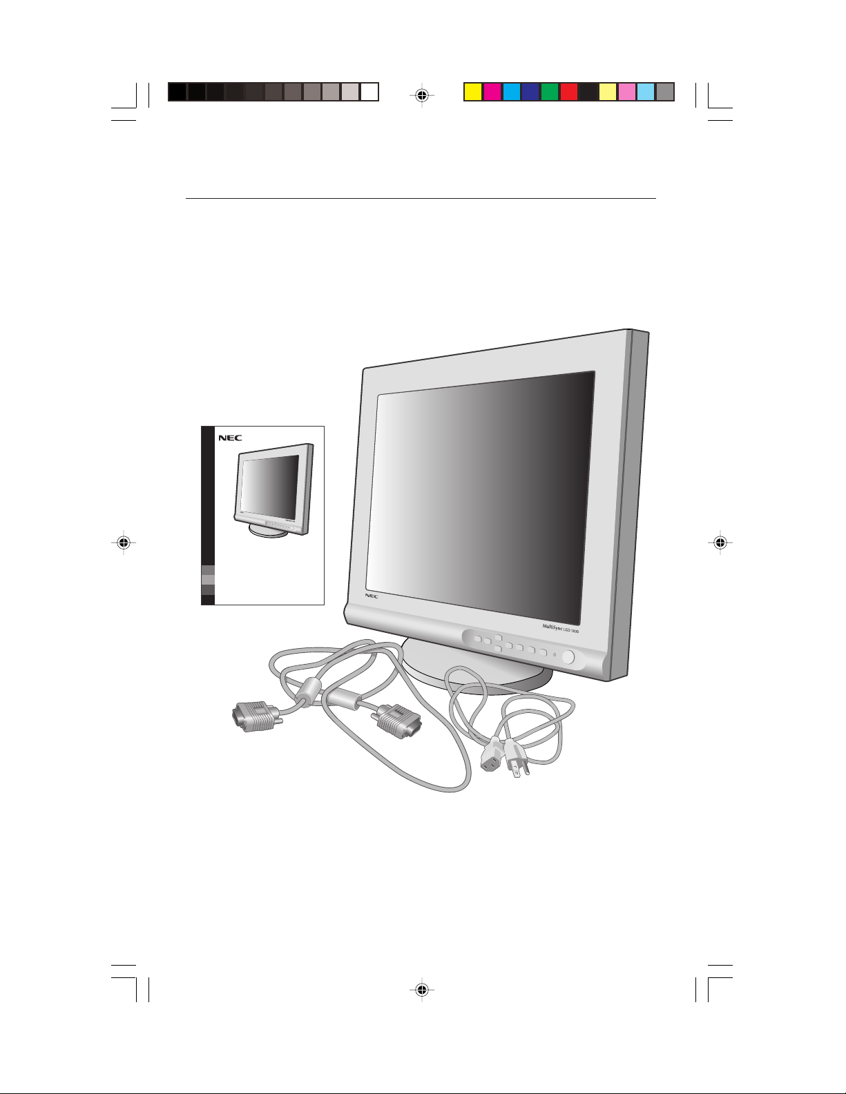
Lieferumfang
Ihr neues MultiSync® LCD Monitor-Paket* von NEC sollte den
nachfolgenden Inhalt umfassen:
• MultiSync LCD Monitor mit Schwenk-/Kipp-/Drehfuß MultiSync® LCD1830
• Netzkabel
• Videosignalkabel
• Benutzerhandbuch
™
USER'S MANUAL
MultiSync
LCD1830
To learn about other special offers, register online at www.necmitsubishi.com/productregistration
* Denken Sie daran, die Originalverpackung und das Verpackungsmaterial für einen späteren Transport bzw.
eine Versendung Ihres Monitors aufzubewahren.
®
™
46
LCD1830.wpc 11/29/00, 9:57 AM48
Page 49

Quick Start
Um den MultiSync® LCD Monitor an Ihrem System zu befestigen, folgen
Sie diesen Anweisungen:
1. Drehen Sie sich von der Macht zu Ihrem Computer.
2. Für den PC: verbinden Sie die 15-Nadel kleiner D-ERSATZ des geeigneten Signal-Kabels zum
Verbindungsstecker der Auslage-Karte in Ihrem System (Figure A.1). Ziehen Sie alle Schrauben fest.
Für den Mac: verbinden Sie den MultiSync LCD1830™ Macintosh Kabel-Anpassungsvorrichtung
zum Computer (Figure B.1). Befestigen Sie die 15-Nadel kleiner D-UNTER Ende des geeigneten
Signal-Kabels zum MultiSync LCD1830 Macintosh Kabel-Anpassungsvorrichtung (Figure B.1).
Ziehen Sie alle Schrauben fest.
NOTIZ: den MultiSync LCD1830 Macintosh Kabel-Anpassungsvorrichtung zu erhalten,
Anruf NEC-Mitsubishi Electronic Display of America, Inc. AG bei (800) 820-1230.
Entfernen Sie Verbindungsstecker, decken Sie und Kabel-Decke auf Rücken von Monitor.
3. Durchverbinde 15- die Nadel den Kleinst D- SUB von dem Videoverfahren zeige Telegramm zum
Verbindungsstecker “INPUT 1” ODER habt “INPUT 2” auf rückwärtig von dem Sichtgerät
(Figure C.1) an.
NOTIZ: Falsche Kabel-Verbindungen resultieren vielleicht in unregelmäßiger Bedienung,
Schaden, zeigen Sie quality/components von LCD Bauelement, und/oder kürzen Sie das
Leben des Bauelementes.
4. Verbinden Sie ein Ende des Netzkabels zur MultiSync LCD Folge Monitor und das andere Ende
zum Macht-Abfluß (Figure C.1). Ersetzen Sie Verbindungsstecker, decken Sie und Kabel-Decke
(Figure E.1).
NOTIZ: Wenn Sie diesen Monitor bei AC220-240V benutzen, beziehen Sie sich bitte auf empfehlen
Verwendung-Teil dieses Handbuches für richtige Auswahl von WECHSELSTROM-Netzkabel.
5. Schalten Sie den Monitor an (Figure D.1) und der Computer.
6. Um den Umstände von Ihrem MultiSync LCD Monitor zu vervollständigen, benutzen Sie die
folgenden OSM™ Kontrollen:
• Auto stellt Kontrast ein
• Auto stellt ein
Beziehen Sie sich auf den Kontrollen-Teil vom Handbuch dieses Benutzers für eine volle
Beschreibung dieser OSM Kontrollen.
NOTIZ:
Für laden Sie Informationen über den Windows 95/98 INF Akte für Ihren MultiSync nach
LCD1830 überwachen, beziehen Sie sich auf den Hinweise-Teil vom Handbuch dieses Benutzers.
NOTIZ: Wenn Sie irgendwelche Probleme haben, beziehen Sie sich bitte auf den Störungssuche-
Teil von das Handbuch dieses Benutzers.
NOTIZ: Für leichte Entfernung des Kabels decken Sie oder Signal-Kabel, setzen Sie den
Monitor-fac hinunter (Figure R.2).
Figure A.1 Figure B.1
LCD1830.wpc 11/29/00, 9:57 AM49
15-pin
mini D-SUB
Mac
Anpassungsvorrichtung
(schloß nicht ein)
47
15-pin
mini
D-SUB
Page 50
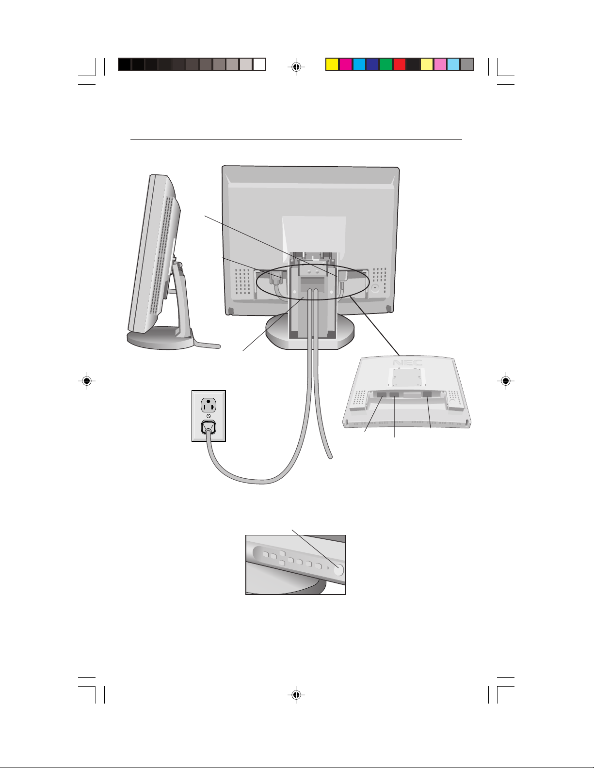
Quick Start –fortsetzung
Figure C.1
AC Power
Cord
Signal
Cable
1. Kabel gehen durch in diesem loch vorbei.
2. Verbinden sie jeden verbindungsstecker.
3. Tausche Verbindungsstecker Schoner mit bestehenden
durch einweihenden Ober Telegrammen aus.
Treiben Sie
Abfluß an
LCD1830.wpc 11/29/00, 9:57 AM50
Power Switch
Figure D.1
48
Zu Computer
INPUT2
INPUT1
AC-IN
Page 51

Quick Start –fortsetzung
2
3
1
Auszeichnenden
Gebiet
(1. Schub )
Marque
Telegramm Bedeckt
Wie zu ausquartieren diesen Schoner.
1. Auszeichnender Gebiet Schub
2. Gleite um den Rand zu up aus
3. Remove
2
LCD1830.wpc 11/29/00, 9:57 AM51
Schub
Figure E.1
49
1
Verbindungsstecker-Decke
Wie zu ausquartieren diesen Schoner.
1. Betreibe unter dem Rand
2. Remove
1
Schub
Page 52
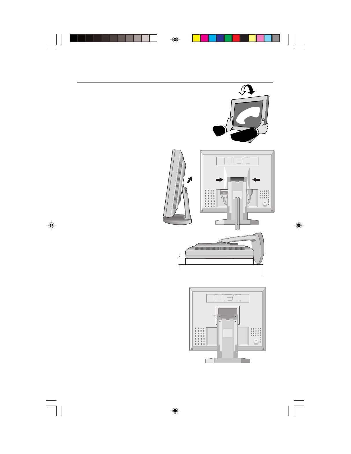
Quick Start –fortsetzung
Neigung
Begreifen Sie beide Seiten des Monitor
Bildschirmes mit Ihren Händen und stellt die
Neigung ein wie gewünscht (Figure TS.1).
Entfernen Sie Monitor, stehen Sie für das
Besteigen Um den Monitor für Ersatz-Einbau
Zwecke vorzubereiten:
1. Entfernen Sie die
VerbindungssteckerDecke, Scharnier-Decke,
und Kabel-Decke (Figure
R.1).
2. Trennen Sie alle Kabel.
3. Stelle-Monitor-Gesicht
entlang auf ein nicht-scharfe
Oberfläche (Stelle der
Bildschirm auf einem 32 mm
Plattform damit Loch
von Einstellung-Wettkampf,
Lage zu schrauben).
(Figure R.2).
4. Entfernen Sie die 4 Schrauben,
die den Monitor zur Einstellung
verbinden, und hebt von der
Einstellung-Versammlung
(Figure R.2) der Monitor ist jetzt
bereit für das Besteigen in einer
anderen Art.
5.
Verbinden Sie die WECHSELSTROMSchnur und das Signal kabeln Sie
zum Rücken des Monitors.
6. Kehren Sie diesen Prozeß zu um
reattach stehen.
Hinweis: Für die Einhaltung der Sicherheits-
Anforderungen muss der Monitor an
einen Schwenkarm montiert werden,
der die notwendige Stabilität unter
Berücksichtigung des Monitorgewichts
garantiert. Der LCD-Monitor darf nur
mit einem zertifizierten Arm (z.B. GS-Zeichen)
verwendet.
32mm
Figure R.1
Screws
Figure TS.1
SCHUB
Figure R.2
SCHUB
LCD1830.wpc 11/29/00, 9:57 AM52
50
Page 53

Bedienungselemente
Mit den vorne am Monitor befindlichen OSM™- (On-Screen Manager)-Tasten werden die
folgenden Funktionen ausgeführt :
Um auf OSM Speisekarte zuzugreifen, drücken Sie keine der Kontrolle-Knöpf. ( , , , )
Um Signal-Eingabe zu verändern, drücken Sie die EINGABE 1/2 Knopf.
Hauptmenü Untermenü
EXIT
CONTROL /
CONTROL /
PROCEED
RESET
HINWEIS: Wird die RESET-Taste im Haupt- oder Untermenü gedrückt, so erscheint ein Warnfenster,
das Ihnen ein Abbrechen der RESET-Funktion durch Betätigung der Taste EXIT ermöglicht.
Helligkeits-/Kontrastregler
HELLIGKEIT
Zur Einstellung der Helligkeit des Gesamtbildes und des Bildschirmhintergrundes.
KONTRAST
Zur Einstellung der Bildhelligkeit in Vergleich zum Hintergrund.
AUTOM. EINST
Paßt das angezeigte Bild an, falls nicht standardmäßige Videoeingangssignale
vorliegen.
Auto Adjust
Paßt die Einstellungen für Image Position, H. Size und Fine automatisch an.
Beendet das OSM-Menü.Führt zum OSM-Hauptmenü zurück.
Verschiebt den hervorgehobenen Verschiebt den hervorgehobenen
Bereich nach oben oder unten, um Bereich nach oben oder unten, um
einen Menüpunkt auszuwählen. einen Menüpunkt auszuwählen.
Verschiebt den hervorgehobenen Verschiebt den Balken nach rechts
Bereich nach rechts oder links, um ein oder links, um die Einstellung zu erhöhen
Steuermenü auszuwählen. oder zu verringern.
Diese Taste hat keine Funktion. Aktiviert die Funktionen Auto Adjust
Schub PROCEED, um zu aktivieren
Auto Berichtigt.
Setzt alle Einstellungen des Setzt die hervorgehobene Einstellung
hervorgehobenen Steuermenüs auf auf die Werkseinstellung zurück.
die Werkseinstellung zurück
Im Werzeug- und Informations-Modus
öpffnet ein zusätzliches Fenster.
LCD1830.wpc 11/29/00, 9:57 AM53
51
Page 54

Bedienungselemente –fortsetzung
Positionsregler
LINKS / RECHTS
Steuert die horizontale Bildposition innerhalb des LCD-Anzeigebereichs.
UNTEN / OBEN
Steuert die vertikale Bildposition innerhalb des LCD-Anzeigebereichs.
AUTOM. EINST
Stellt die horizontale und die vertikale Bildposition innerhalb des LCDAnzeigebereichs automatisch ein.
Bildanpassungsregler
BILDPUNKTE
Paßt die horizontale Bildgröß e durch Erhöhen oder Verringern der Einstellung an.
STABILITÄT
Verbessert Schärfe, Klarheit und Stabilität des Bildes durch Erhöhen oder
Verringern der Einstellung.
AUTOM. EINST
Die BILDPUNKTE und STABILITÄT-Einstellungen werden automatisch ausgeführt.
AccuColor® Control System
Fünf streicht, presets auszusuchen das begehrende auslös Kolorit an. presets,
seid und von dem Kolorit zwei cannot üblich wird verändert. Color Temperatur
beschleunigt, oder dezimiert in jeglichem preset. Auslegenden, daß die
Nummer von Koloriten dezimiert werden kann.
R,Y,G,C,B,M,S: Ve rgrößerungen oder Reduzierungen Rot, Gelb, Grün, Cyan,
Blue, Magentarot und abhängende Sättigung auf welcher wird ausgesucht. Die
Veränderung in Kolorit wird auf Raster und der Richtung (Vergrößerung
scheinen oder wird dezimieren) wird beim Kolorit bezeugt werden Bars.
Werkzeuge 1
WEICH ZEICHNEN: Wählen Sie eine der drei Bildschärfeeinstellungen aus.
Diese Funktion kann nur aktiviert werden, wenn die Funktion zur Vergrößerung
der Anzeige (EXPANSION) aktiviert ist.
TEXT MODUS: Damit wird der Displaytext deutlich angezeigt.
NORMALER MODUS: Diese Schärfe liegt zwischen TEXT und GRAPHIK MODUS.
GRAPHIK MODUS: Dieser Modus ist für Bilder und Fotos geeignet.
EXPANSIONS MODUS: Stellt das Zoom-Verfahren ein.
GANZER BILDSCHIRM: Das Bild wird ungeachtet der Auflösung auf
1280 x 1024 vergrößert.
SEITENMASSE BLEIBEN: Das Bild wird ohne Änderung des Bildformats
vergrößert.
KEINE EXPANSION: Das Bild wird nicht vergrößert.
LCD1830.wpc 11/29/00, 9:57 AM54
52
Page 55
Bedienungselemente –fortsetzung
SIGNAL PRIORITÄT: Zur Wahl des Verfahrens zur Erkennung des Videosignals,
wenn zwei Rechner an den Monitor angeschlossen sind.
KEINES: Der Monitor sucht nur im eingeschalteten Zustand den anderen
Videoeingang.
ERSTES SIGNAL: In dieser Stellung schaltet der Monitor automatisch nur
dann auf den anderen Eingang um, wenn am ersten kein Signal mehr anliegt.
LETZTES SIGNAL: In dieser Stellung schaltet der Monitor stets auf den
anderen Eingang um, wenn am ersten kein Signal mehr anliegt oder sobald
am zweiten ein Signal anliegt.
Werkzeuge 2
SPRACHAUSWAHL: OSM™-Systemsteuerungsmenüs stehen in sieben Sprachen
zur Verfügung.
OSM POSITION: Sie können wählen, wo das OSM-Menü/Fenster auf dem
Bildschirm erscheinen soll. Die Wahl des OSM-Platzes ermöglicht Ihnen die
manuelle Einstellung der Position, d.h.links, rechts, obenoderunten, des OSMSystemsteuerungsmenüs.
OSM ANZEIGEDAUER: Das OSM-Systemsteuerungsmenü bleibt eingeschaltet
solange es benutzt wird. Im OSM-Ausschaltzeit-Untermenü können Sie wählen,
wie lange der Bildschirm nach der letzten Betätigung einer Schaltfläche wartet,
bis das OSM-Systemsteuerungsmenü ausgeschaltet wird. Die voreingestellten
Wahlmöglichkeiten sind 10,20,30,60 und 120 Sekunden.
OSM ABSCHALTUNG: Diese Funktion blockiert den Zugang zu allen OSMSteuerfunktionen. Wenn Sie in der gesperrten Betriebsart versuchen, eine
OSM-Steuerung zu aktivieren, dann erscheint ein Bildschirmfenster, auf dem
die gesperrten OSM-Steuerungen angezeigt sind. Um den ABSCHALTUNGModus zu aktivieren, halten Sie gleichzeitig die PROCEED und Taste
gedrückt. Um den ABSCHALTUNG-Modus zu deaktivieren, drücken Sie wieder
gleichzeitig die PROCEED und Taste.
WERKSEINSTELLUNG: Indem Sie die im Werk vorgenommenen
Voreinstellungen wählen, können Sie alle OSM-Steuereinstellung auf die
werksseitigen Einstellungen zurückstellen. Dabei muß die RESET-Taste ein paar
Sekunden lang gedrückt gehalten werden, um diese Rückstellung zu bewirken.
Individuelle Einstellungen können zurückgestellt werden, indem die jeweilige
Steuerung markiert und dann durch Betätigung der RESET-Taste zurückgestellt
wird.
AUFLÖSUNGSANZEIGE: Die optimale Auflösung ist 1280 x 1024. Wenn ON
gewählt wurde, erscheint 30 Sekunden später eine Mitteilung auf dem
Bildschirm, wenn die Auflösung nicht 1280x1024 beträgt.
LCD1830.wpc 11/29/00, 9:57 AM55
53
Page 56
Bedienungselemente –fortsetzung
Information
GRAFIK MODUS: Liefert Information über die derzeitige Auflösung auf dem
Bildschirm sowie technische Daten einschließlich der benutzten Voreinstellzeit
sowie der horizontalen und vertikalen Frequenzen.
MONITORINFORMATION: Zeigt Modell-und Seriennummern des Monitors.
OSM™ Warnung
OSM ermahnenden Speisezettel macht mit Ausgang EXIT davon.
KEIN SIGNAL: Warnung,wenn kein Signal anliegt. Dieses Fenster
erscheint, wenn nach dem Einschalten des Monitors oder dem
Wechseln des Eingangssignals kein Videosignal anliegt.
AUFLÖSUNGSANZEIGE: Warnt vor nicht optimierter Auflösung. Dieses
Fenster erscheint, wenn nach dem Einschalten des Monitors oder dem
Wechseln des Eingangssignals das Videosignal nicht die optimale
Auflösung hat. Diese Funktion kann mit dem TOOL-Menüdeaktiviert
werden.
FREQUENZ ZU HOCH: Empfiehlt die optimale Auflösung und Bildfrequenz.
Dieses Fenster erscheint, wenn nach dem Einschalten des Monitors oder
dem Wechseln des Eingangssignals das Videosignal nicht das
geeignete Timing hat.
KABLE PRÜFEN: Dieses Festveranstaltung wird Sie beraten, um dämmen
alles Videoverfahren Gibt auf dem Sichtgerät und Rechenanlage, um zu
vergewissern sie werden richtig durchverbunden ein.
LCD1830.wpc 11/29/00, 9:57 AM56
54
Page 57

Empfehlungen für die Verwendung
Vorsichtsmaßnahmen und Wartung
UM DIE OPTIMALE LEISTUNGSFÄHIGKEIT IHRES MULTISYNC LCD
FARBMONITORS ZU GEWÄHRLEISTEN, SOLLTEN SIE BEI DER
AUFSTELLUNG UND VERWENDUNG IHRES GERÄTES
DIE FOLGENDEN PUNKTE BEACHTEN
•ÖFFNEN SIE DEN MONITOR NICHT. Im Inneren des Gerätes befinden sich keine Teile, die vom Benutzer
selbst gewartet werden können. Das Öffnen oder Entfernen der Abdeckungen könnte einen elektrischen
Schock verursachen oder zu anderen gefährlichen Situationen führen. Wartungs- und Reparaturarbeiten
dürfen nur von qualifizierten Service-Technikern ausgeführt werden.
• Vermeiden Sie das Eindringen von Flüssigkeiten in das Gerät und benutzen Sie den Monitor niemals in
der Nähe von Wasser.
• Stecken Sie keinerlei Gegenstände durch die Gehäuseschlitze in das Gerät. Diese könnten gefährliche
Spannungspunkte im Geräteinneren berühren und einen elektrischen Schlag, einen Brand oder ein
Versagen des Gerätes verursachen.
• Stellen Sie keine schweren Geräte auf das Netzkabel. Eine Beschädigung des Netzkabels kann einen
elektrischen Schlag oder Brand verursachen.
• Stellen Sie das Gerät niemals auf unebenen oder instabilen Gestellen, Unterlagen oder Tischen auf. Der
Monitor könnte herunterfallen und schwer beschädigt werden.
• Der Netzstecker ist das wichtigste Teil zum Trennen des Monitors vom. Der Monitor sollte in der Nöhe
einer leicht zugänglichen Netzsteckdose installiert werden.
• Wenn Sie den MultiSync® LCD mit seiner weltweiten AC 220-240 V Stromversorgung betreiben,
verwenden Sie ein Netzkabel, das der Speisungsspannung der verwendeten Wechselstromsteckdose
entspricht. Das verwendete Netzkabel muß den Sicherheitsnormen Ihres Landes entsprechen und gemäß
dieser zugelassen sein. (Außer in Euopa sollte die Type H05VV-F verwendet werden).
• In Großbritannien ein für den Betrieb des Monitors vom BS zugelassenes Netzkabel mit einem
integrierten Stecker mit schwarzer Sicherung (5A). Wenn zusammen mit diesem Monitor kein Netzkabel
geliefert wird, wenden Sie sich bitte an Ihren Lieferanten.
• Stellen Sie keine Gegenstände auf den Monitor, und benutzen Sie den Monitor necht draußen.
• Die Leuchtstoffröhre im Inneren des LCD-Monitors enthält Quecksilber. Halten Sie sich bei der Entsorgung
dieser Leuchtstoffröhre bitte an die anwendbaren lokalen Gesetze und Vorschriften.
Bei Eintreten der im nachfolgenden angeführten Umstände muß der Monitor sofort vom Netz getrennt und
ein Service-Techniker konsultiert werden:
• Wenn das Netzkabel oder der Netzstecker beschädigt ist.
• Wenn Flüssigkeit oder Gegenstände in das Monitorgehäuse geraten sind.
• Wenn der Monitor Regen ausgesetzt war oder mit Wasser in Berührung gekommen ist.
• Wenn der Monitor fallen gelassen bzw. das Gehäuse beschädigt wurde.
• Wenn der Monitor trotz Befolgung der Bedienungsanleitung nicht ordnungsgemäß funktioniert.
VORSICHT
• Achten Sie auf eine ausreichende Rundum-Belüftung des Monitors, damit die Wärme
richtig entweichen kann. Die Lüftungsschlitze dürfen nicht blockiert werden, und der
Monitor darf nicht in der Nähe einer Heizung oder einer sonstigen Wärmequelle
aufgestellt werden. Stellen Sie keine Gegenstände auf den Monitor.
• Der Netzstecker ist das wichtigste Teil zum Trennen des Monitors vom Netz. Der Monitor
sollte in der Nähe einer leicht zugänglichen Netzsteckdose installiert werden.
• Vorsich, wenn das Tragen des Monitors, als der Kompatite Standplatz automatisch sich
aus dehen kann.
• Transportieren Sie den Monitor mit äußerster Vorsicht. Bewahren Sie das
Verpackungsmaterial für einen späteren Transport auf.
• Beuge die Power Anschlußschnur.
• Gebrauche Ihr Sichtgerät in feuchten, staubigen, hohen Temperaturen oder near Öl.
• Bedecke den Schrank Schlitz oder Verwendung habt den üblen Vorlauf ausgeströmt.
• Wenn Glas gebrochen wird, handhaben Sie mit Sorge.
• Leckerbissen glass immer mit Versorgung.
• Berühre die Flüssigkeit crystal wenn Ihr Sichtgerät brechenden hat.
LCD1830.wpc 11/29/00, 9:57 AM57
55
Page 58

Empfehlungen für die Verwendung
–fortsetzung
EINE KORREKTE AUFSTELLUNG UND EINRICHTUNG DES MONITORS
KANN BEIM ARBEITEN AM BILDSCHIRM AUGEN, NACKEN- UND
SCHULTERMUSKULATUR ENTLASTEN. BEACHTEN SIE BEIM
AUFSTELLEN DES MONITORS BITTE DIE FOLGENDEN PUNKTE:
• Lassen Sie den Monitor 20 Minuten lang aufwärmen, um
optimale Leistung sicherzustellen.
• Passen Sie die Höhe des Monitors so an, daß der obere
Bildschirmrand sich in oder geringfügig unter Ihrer
Augenhöhe befindet. Wenn Sie die Bildschirmmitte
betrachten, sollten Ihre Augen leicht nach unten blicken.
• Der Abstand vom Auge zum Monitor sollte nicht weniger als
40 cm und nicht mehr als 70 cm betragen. Der optimale
Abstand beträgt 50 cm beim MultiSync® LCD
• Entspannen Sie Ihre Augen regelmäßig durch Fixieren eines
Gegenstandes in mindestens 6 m Entfernung. Blinzeln Sie
häufig.
• Stellen Sie den Monitor in einem Winkel von 90° zum Fenster und anderen Lichtquellen auf, um
Blendungen und Reflexionen auf dem Bildschirm soweit wie möglich zu vermeiden. Stellen Sie die
Neigung Ihres Monitors so ein, daß durch Deckenbeleuchtung verursachte Spiegelungen auf dem
Bildschirm vermieden werden.
• Wenn reflektierendes Licht Ihnen das Erkennen der Bildschirmanzeige erschwert, benutzen Sie einen
Anti-Reflexionsfilter.
• Reinigen Sie Ihren Monitor regelmäßig. Verwenden Sie ein fusselfreies und nicht kratzendes Tuch
und eine nicht alkoholhältige, neutrale, nicht scheuernde Reinigungslösung bzw. einen
Glasreiniger, um den Staub zu entfernen.
• Stellen Sie die Helligkeit und den Kontrast Ihres Monitors so ein, daß die Lesbarkeit erhöht wird.
• Bringen Sie in der Nähe des Monitors einen Vorlagenhalter an.
• Plazieren Sie entweder den Monitor oder das Referenzmaterial (je nachdem, worauf Sie am
häufigsten blicken) direkt vor sich, damit Sie den Kopf beim Schreiben so wenig wie möglich
drehen müssen.
• Vermeiden Sie es, Standbilder über längere Zeiträume auf dem Monitor anzuzeigen, damit keine
Bildschatten entstehen (Nachbildwirkung).
• Lassen Sie Ihre Augen regelmäßig untersuchen.
Ergonomie
Zum Erzielen eines maximalen ergonomischen Nutzens empfehlen wir eine Berücksichtigung der
folgenden Punkte:
• Passen Sie die Helligkeit an, bis der Hintergrundraster nicht mehr sichtbar ist
• Stellen Sie den Kontrastregler nicht auf den Höchstwert ein
• Verwenden Sie bei Standardsignalen die Voreinstellungen für die Größen- und Positionsregler
• Verwenden Sie die Voreinstellungen für Color Setting und Sides Left/Right
• Verwenden Sie Signale ohne Zeilensprung mit einer vertikalen Bildauffrischrate zwischen 60 und
75 Hz
• Verwenden Sie die Primärfarbe Blau nicht vor einem dunklen Hintergrund, da sie schlecht zu
sehen wäre und aufgrund des unzureichenden Kontrasts zu einer Überanstrengung der Augen
führen könnte
Nähere Informationen über die Einrichtung einer gesunden Arbeitsumgebung erhalten Sie, wenn Sie NEC unter der
Telefonnummer (800) 820-1230 bzw. NEC FastFacts
das Dokument # 900108 anfordern. Sie können auch über The Human Factors Society, Inc. P.O. Box 1369, Santa
Monica, California 90406, USA, die Norm American National Standard für Human Factors Engineering of Visual
Display Terminal Workstations - ANSI.-HFS Standard No. 100-1988 bestellen.
™
1830
.
™
unter der Telefonnummer (800) 366-0476 kontaktieren und
LCD1830.wpc 11/29/00, 9:57 AM58
56
Page 59
Technische Daten
Technische Daten MultiSync
Monitor LCD1830
LCD Modul Diagonal: 51 cm (18.1 Zoll) Aktive Matrix, Dünnfilmtransistor (TFT),
dem Monitor entsprechende Auflösung (Pixel-Count):
Eingangssignal Video: ANALOG 0,7 Vp-p / 75 Ohm
Display-Farben Analoges Eingangssignal: 16,777,216 Abhängig von der benutzten Grafikkarte und Signaltiming
Das Ansehen von Winkel Links / Direkt: ± 80°
Synchronisationsbereich Horizontal: 24 kHz bis 82 kHz Automatisch
Unterstützte Auflösungen 720 x 400*
Aktivanzeige Horiz.:
Netzspannung
Current rating 0,8 A @ 100–120 V, 0,4 A @ 220-240 V
Abmessungen
Gewicht 8,5 kg
Umweltbedingungen
Sichtbare Bildgröße: 51 cm (18.1 Zoll) Flüssigkristallanzeige (LCD), 0,28 mm,
Auf / Entlang: ± 80°
Vertikal: 55 Hz bis 85 Hz Automatisch
1280 x 1024 Punktabstand XtraView™-Technologie,
Sync: Separate Sync. TTL-Level
Horizontal Sync. positiv / negativ
Vertikal Sync. positiv / negativ
Gesamt Sync. positiv / negativ
Sync. on Green (Video 0.7p-p and Sync 0,3V p-p)
640 x 480*1 @ 60 Hz bis 85 Hz
800 x 600*1 @ 56 Hz bis 85 Hz
832 x 624*1 @ 75 Hz
1024 x 768*1 @ 60 Hz bis 85 Hz
1152 x 864*
1152 x 900*
1280 x 960*
1280 x 1024
359 mm/14.1 Zoll
Vert.:
287 mm/11.3 Zoll
AC 100 V - 120 V
435 mm (B) x 449 mm (H) x 215 mm (T)
17.1 Zoll (B) x 17.7 Zoll (H) x 8.5 Zoll (T)
18,7 Pfund
Betriebstemperatur: 5° C bis +35° C/41°F bis 95° F
Luftfeuchtigkeit: 30 % bis 80 %
Höhe: 0 bis 12,000 Fuß
Lagertemperatur: -10° C bis +60° C/-14° F bis 140° F
Luftfeuchtigkeit: 10 % bis 85%
Höhe: 0 bis 53,300 Fuß
®
™
Monitor
1
@ 70 Hz
1
@ 75Hz
2
@ 66Hz
2
@ 60Hz bis 75Hz
@ 60 Hz bis 76 Hz ................
/220–240 V
@ 50/60Hz
Remarques
200 cd/m2, weiße Leuchtdichte,
Kontrastverhältnis 300:1, typisch.
Einige Systeme unterstützen unter
nicht alle der aufgelisteten Modi.
Für optimale Darstellungsleitung des Monitors
und Farben empfiehlt NEC eine Auflösung bei 60 Hz
Umstände
*1Interpolierte Auflösungen. Wenn Auflösungen angezeigt werden, die geringer als der Pixel-Count des LCD-Moduls sind, können Buchstaben „stufig“
erscheinen oder Linien fett aussehen. Das ist normal und bei allen gegenwärtig zur Verfügung stehenden Flachbildschirmtechnologien notwendig, wenn
Auflösungen, die dem Monitor nicht entsprechen, in Ganzbildschirmgröße angezeigt werden. Bei Flachbildschirmen ist jeder Punkt auf dem Bildschirm ein
Pixel, d.h. wenn man die Auflösung auf Ganzbildschirmgröße vergrößert, muß eine Interpolation der Auflösung vorgenommen werden. Wenn die
interpolierte Auflösung nicht ein ganzes Vielfaches der eigenen Auflösung des Bildschirms ist, kann die mathematische Interpolation dazu führen, daß
manche Linien dicker als andere aussehen.
2
Die Anzahl der Farben, angezeight werden können nimmt ab.
*
ANMERKUNG: Technische Spezifikationen können ohne vorherige Ankündigung geändert werden.
57
LCD1830.wpc 11/29/00, 9:57 AM59
Page 60

Funktionen
Reduzierte Fußstapfe: versorgt Umgebungen, die überlegene Bild-Qualität erfordern, mit
der idealen Lösung, aber mit Größe und Gewicht-Einschränkungen. Die kleine Fußstapfe
des Monitors und niedriges Gewicht erlauben ihm, bewegt zu werden oder transportierten
leicht von einer Lage zu noch ein.
AccuColor® Beherrsche Systematiken:, Sechs Kolorit presets auszusuchen, color auslös die
begehrenden (sRGB und URWÜCHSIG kolorit presets, seid und cannot üblich wird
verändert). Color Temperatur beschleunigt, oder dezimiert, in jeglichem preset.
R,Y,G,C,B,M,S: Vergrößerungen oder Reduzierungen Rot, Gelb, Grün, Cyan, Blue,
Magentarot und abhängende Sättigung auf welcher wird ausgesucht. Die Veränderung in
Kolorit wird auf Raster und der Richtung (Vergrößerung scheinen oder wird dezimieren)
wird beim Kolorit bezeugt werden Bars. URWÜCHSIG: Urschriftliches Kolorit hat bei den
LCD beschenkt täfele, daß unadjustable ist.
sRGB: sRGB Form bessert die color Tonwiedergabe, in der desktop Umwelt dramatisch eine
mal einzigen üblichen RGB streicht Weltall an. Mit diesem Kolorit habt Umwelt der Operator befürwortet, could leicht und selbstsicher verständige color ohne sonst color Verwaltung
overhead in meisten Gemeindeland Sachlagen. Die Form Leuchtkraft und Schattenspiel
Steuerungen werden Darin vereist, um die runde color Leistungsfähigkeit zu versichern.
OSM™ -Einstellfunktionen (On-Screen-Manager): Erlauben es Ihnen, alle Elemente Ihres
Monitorbilds mit Hilfe einfach und rasch zu verwendender On-Screen-Menüs anzupassen.
ErgoDesign
verbessern, die Gesundheit des Benutzers zu schützen und Geld zu sparen. Beispielsweise
stehen OSM™-Einstellfunktionen für rasche und einfache Bildanpassung und ein Schwenk/Drehfuß für die Einstellung des bevorzugten Blickwinkels zur Verfügung. Außerdem
entspricht das Gerät den MPRII und TCO- Richtlinien für verringerte Emissionen.
Plug-and-Play: Die Microsoft®-Lösung mit dem Betriebssystem Windows®95/98
erleichtert die Einrichtung und Installation, indem die Eigenschaften des Monitors (z.B.
Bildschirmgröße und unterstützte Auflösungen) direkt vom Monitor an den Computer
übermittelt werden, wodurch die Anzeige automatisch optimiert wird.
IPM™ -System (Intelligent Power Manager): Bietet innovative Energiesparmethoden, die es
dem Monitor erlauben, auf einen geringeren Stromverbrauch zurückzuschalten, wenn er
zwar eingeschaltet ist, aber gerade nicht benutzt wird. So können Sie zwei Drittel der
Stromkosten für den Monitorbetrieb sparen, die Emissionen reduzieren und gleichzeitig
die Kosten für die Klimatisierung des Arbeitsplatzes verringern.
Mehrfrequenztechnologie: Der Monitor wird automatisch auf die Abtastfrequenz der
Grafikkarte eingestellt, wodurch das Bild in der erforderlichen Auflösung angezeigt wird.
FullScan™: Erlaubt es Ihnen, in den meisten Auflösungsbereichen die gesamte
Bildschirmfläche zu nutzen, wodurch die Bildgröße signifikant gesteigert wird.
XtraView® Weitwinkeltechnologie: Damit kann der Benutzer den Monitor in jeder
Ausrichtung -d.h.im Hoch-oder Querformat -aus jedem Winkel (160°) betrachten. Voller
160°-Blickwinkel entweder nach oben, unten, links oder rechts.
VESA Standardmontagevorrichtung: Damit kann der MultiSync Monitor an jedem
standardmäßigen VESA-Montagearm oder Halter von Drittlieferanten montiert werden. So
kann der Monitor unter Verwendung einer kompatiblen Montagevorrichtung eines
Drittlieferanten an einer Wand oder an einem Tragarm montiert werden.
®
: Verbessert die ergonomischen Eigenschaften, um die Arbeitsumgebung zu
OSM Display Screen Copyright 2000 by
NEC-Mitsubishi Electronic Display of America, Inc.
58
LCD1830.wpc 11/29/00, 9:57 AM60
Page 61

Fehlerbehebung
Kein Bild
• Das Signalkabel muß ordnungsgemäß an die Grafikkarte / den Computer angeschlossen sein.
• Vergewissern Sie sich, daß die Grafikkarte vollständig eingeschoben ist.
• Vergewissern Sie sich, daß der Einschaltknopf des Monitors und der Einschaltknopf des
Computers auf ON stehen.
• Vergewissern Sie sich, daß auf der Grafikkarte oder im verwendeten System ein unterstützter
Modus ausgewählt wurde. (Nähere Informationen zur Änderung des Grafikmodus entnehmen
Sie bitte dem Handbuch zu Ihrer Grafikkarte oder zu Ihrem System.)
•Überprüfen Sie den Monitor und Ihre Grafikkarte auf Kompatibilität und vergewissern Sie sich,
daß die empfohlenen Einstellungen eingehalten werden.
•Überprüfen Sie den Signalkabelanschluß auf verbogene oder eingedrückte Kontaktstifte.
• Die Scheck Signal Versorgung, “INPUT 1” oder habt “INPUT 2”.
Bild-Beharrlichkeit
• Image Beharrlichkeit ist wenn ein “Geist” von ein Bild-Überreste auf dem Bildschirm sogar,
nachdem der Monitor ausgemacht worden ist. Anders als CRT Monitoren überwacht LCD, ' Bild
Beharrlichkeit ist nicht bleibend. Um Bild-Beharrlichkeit zu erleichtern, dreht den Monitor weg für,
so lang wie einem Bild es gezeigt wurde. Wenn ein Bild auf dem Monitor für eine Stunde und
einen ”ghost wäre,” von diesen Bild-Überreste sollte der Monitor eine Stunde ausgemacht
werden, um das Bild auszuradieren.
HINWEIS: NEC-Mitsubishi Electronics Display empfiehlt, wie für alle persönlichen
Anzeigegeräte, die regelmäßige Verwendung eines Screensavers, der sich einschaltet, wenn
das angezeigte Bild länger unverändert bleibt.
Das Bild ist instabil, unscharf oder verschwimmt
• Vergewissern Sie sich, daß das Signalkabel ordnungsgemäß an den Computer angeschlossen ist.
• Verwenden Sie die OSM™-Bildanpassungsfunktionen, um die Anzeige scharf zu stellen und das
Bild entsprechend anzupassen, indem Sie die Feineinstellungen je nachdem höher oder niedriger
stellen. Wenn der Anzeigemodus geändert wird, müssen unter Umständen die OSMBildanpassungseinstellungen nachgestellt werden.
• Überprüfen Sie Ihren Monitor und Ihre Grafikkarte auf Kompatibilität und vergewissern Sie sich,
daß das empfohlene Signaltiming eingehalten wird.
• Wenn text verunstaltet angezeigt wird, stellen Sie den videomodus auf ohne zeilensprung und
verwenden Sie eine Bildauffrischrate von 60Hz.
LED am Monitor leuchtet nicht (keine grüne oder gelbe Farbe sichtbar)
• Vergewissern Sie sich, daß der Einschaltknopf auf ON steht und daß das Netzkabel
ordnungsgemäß angeschlossen ist.
• Vergewissern Sie sich, daß sich der Computer nicht in einem Energiesparmodus befindet
(berühren Sie die Tastatur oder die Maus).
Das Bild hat nicht die richtige Größe
• Verwenden Sie die OSM-Bildanpassungsfunktionen, um die horizontale Größe zu vergrößern
oder zu verkleinern.
• Vergewissern Sie sich, daß auf der verwendeten Grafikkarte bzw. im verwendeten System ein
unterstützter Modus und unterstütztes Signaltiming ausgewählt wurde (Nähere Informationen zur
Änderung des Grafikmodus oder der Bildauffrischrate entnehmen Sie bitte dem Handbuch zu
Ihrer Grafikkarte bzw. zu Ihrem System).
Kein Bild
• Schalten Sie den Monitor einmal aus und wieder ein.
LCD1830.wpc 11/29/00, 9:57 AM61
59
Page 62

Verweise
• BBS (978) 742-8706
Das Remote Bulletin Board System von NEC-Mitsubishi Electronics Display ist
ein elektronischer Service, den Sie mit Hilfe Ihres Systems und eines Modems
nutzen können. Die Kommunikationsparameter lauten: 300/1200/2400/
9600/14,4k/28,8k/33.6 k bps, keine Parität, 8 Datenbits, 1 Stopbit
• Kundendienst/
Technischer Support (800) 632-4662
Fax (978) 742-7049
• Elektronische Kommunikationskanäle:
Internet E-mail: tech-support@necmitsubishi.com
Internet ftp-Site: ftp.necmitsubishi.com
World Wide Web: http://www.necmitsubishi.com
Product Registration: http://www.necmitsubishi.com/productregistration
Europäische Operationen: http://www.nec-monitors.com
Windows® 95/98/2000 INF File:
• FastFacts™-Information (800) 366-0476
INFORMATION BESCHREIBUNG DOKUMENT Nr.
Glossar Definition von Ausdrücken in 900203
Weitere Informationen Namen und Adressen anderer 900204
Anschluß an Macintosh-Geräte Detaillierte Informationen über 153006
Gesundes Arbeitsumfeld Detaillierte Informationen über 900108
• Literatur & Vertriebsinformationen (800) NEC-INFO [(800) 632-4636]
• MultiSync Bestellungen (800) 820-1230
• Tele-Vertrieb (800) 284-4484
http://support.necmitsubishi.com/software.htm
Laden Sie die Datei NECMSINF.ZIP herunter
bezug auf Funktionen,
Eigenschaften und die
Installation des MultiSync® Monitors
Gruppen, die in bezug auf die
Standards und Eigenschaften des
MultiSync Monitors kontaktiert
werden können
den Anschluß von MultiSync
Monitoren an Macintosh-Computer
die Einrichtung eines gesunden
Arbeitsumfelds
[Software und Zubehör]
LCD1830.wpc 11/29/00, 9:57 AM62
60
Page 63

Beschränkte Gewährleistung
NEC-Mitsubishi Electronics Display of America, Inc. (nachstehend als „ NMD-A “ bezeichnet) garantiert hiermit,
daß dieses Produkt keinerlei Material- und Verarbeitungsfehler aufweist, und verpflichtet sich unter den
nachstehenden Bedingungen dazu, innerhalb eines Zeitraums von drei (3) Jahren nach dem Datum des ersten
Erwerbs durch einen Verbraucher jedweden Teil des gegenständlichen Produkts, der sich als defekt erweist, (nach
alleinigem Ermessen von NMD-A) entweder zu reparieren oder zu ersetzen. Auf Ersatzteile werden neunzig (90)
Tage Garantie gewährt. Die als Ersatz zur Verfügung gestellten Teile und Einheiten, bei denen es sich um neue
oder um gebrauchte, wiederinstandgesetzte Komponenten handeln kann, werden bezüglich ihrer technischen
Daten den ursprünglichen Teilen oder Einheiten entsprechen.
Diese Garantie gewährt Ihnen bestimmte Rechte. Darüber hinaus haben Sie möglicherweise weitere Rechte, die
sich jedoch von Bundesstaat zu Bundesstaat unterscheiden. Diese Garantie beschränkt sich auf den ursprünglichen
Käufer des Produkts und ist nicht übertragbar. Sie erstreckt sich lediglich auf Komponenten, die von NMD-A
geliefert wurden. Service, der aufgrund von Komponenten erforderlich wird, die von Dritten geliefert wurden, ist
von der gegenwärtigen Garantie ausgeschlossen. Um unter die gegenwärtige Garantie zu fallen, muß das Produkt
vom ursprünglichen Käufer in den USA oder in Kanada erworben worden sein. Diese Garantie erstreckt sich nur
auf von NMD-A in den USA oder in Kanada vertriebene Produkte. Außerhalb der USA bzw. Kanadas werden
keine Garantieleistungen erbracht. NMD-A wird einen Kaufnachweis fordern, um das Kaufdatum zu überprüfen.
Als Kaufnachweis ist eine Originalrechnung oder -quittung erforderlich, auf der der Name und die Anschrift des
Verkäufers und des Käufers sowie die Seriennummer des Produkts vermerkt sind.
Um Garantieleistungen unter der vorliegenden Garantie in Anspruch zu nehmen, sind Sie verpflichtet, das Produkt
entweder in der Originalverpackung oder einer gleichwertigen Art von Verpackung, die gleichwertigen Schutz
bietet, auf eigene Kosten an den lizenzierten Händler, bei dem Sie das Produkt erworben haben, oder an jede
sonstige von NMD-A genehmigte Einrichtung zu senden (Postgebühren sind im voraus zu entrichten) oder liefern
zu lassen. Produkte dürfen nur nach vorheriger Genehmigung zu Servicezwecken an NMD-A übermittelt
werden. Diese Genehmigung ist unter der Telefonnummer 1-800-632-4662 einzuholen. Das betreffende Produkt
darf zuvor lediglich von Serviceeinrichtungen, die von NMD-A zur Erbringung derartiger Leistungen autorisiert
wurden, verändert, repariert oder gewartet worden sein. Die Seriennummer des Produkts darf nicht geändert oder
entfernt worden sein.
Produkte, die dazu verwendet wurden, Standbilder über längere Zeiträume anzuzeigen, und die dadurch einen
Bildschatten (Nachbildwirkung) erlitten haben, sowie Geräte die durch Unfälle, Mißbrauch oder unsachgemäße
Verwendung geschädigt oder entgegen der im Benutzerhandbuch enthaltenen Anweisungen verwendet wurden,
sind von der vorliegenden Garantie ausgeschlossen. Jedwede derartigen Umstände machen die vorliegende
Garantie null und nichtig.
NMD-A ÜBERNIMMT ÜBER DIE OBENGENANNTE HAFTUNG HINAUS KEINERLEI HAFTUNG FÜR DIREKTE
ODER INDIREKTE SCHÄDEN, BEGLEIT- ODER FOLGESCHÄDEN ODER JEGLICHE SONSTIGE ART VON
SCHÄDEN, DIE AUF DEN GEBRAUCH JEDWEDEN PRODUKTS VON NMD-A ZURÜCKZUFÜHREN SIND. DIESE
GARANTIE ERSETZT SÄMTLICHE SONSTIGEN AUSDRÜCKLICHEN ODER IMPLIZITEN GARANTIEN. DIES
SCHLIESST UNTER ANDEREN DIE IMPLIZITE GARANTIE DER VERMARKTBARKEIT ODER DER EIGNUNG FÜR
EINEN BESTIMMTEN ZWECK MIT EIN. IN EINIGEN BUNDESSTAATEN IST DER AUSSCHLUSS IMPLIZITER
GARANTIEN ODER DIE BESCHRÄNKUNG ODER DER AUSSCHLUSS DER HAFTUNG FÜR BEGLEIT- ODER
FOLGESCHÄDEN NICHT ZULÄSSIG, D.H. DIE OBENGENANNTEN AUSSCHLASSE ODER BESCHRÄNKUNGEN
GELTEN FÜR SIE UNTER UMSTÄNDEN NICHT.
Die Gewährleistung für dieses Produkt wird gemäß der Bestimmungen der vorliegenden beschränkten Gewährleistung
übernommen. Die Verbraucher werden hiermit darauf aufmerksam gemacht, daß die Leistung des Produkts von
der Systemkonfiguration, der Software, der Anwendung, den Kundendaten und der Steuerung des Systems seitens
des Bedieners sowie von anderen Faktoren beeinflußt wird.
NMD-A -Produkte gelten als mit vielen Systemen kompatibel, doch können spezifische funktionelle Anwendungen
des Produkts seitens des Käufers variieren. Deshalb muß die Eignung eines Produktes für einen spezifischen Zweck
oder eine spezifische Anwendung vom Käufer festgestellt werden und wird von NMD-A nicht gewährleistet.
Den Namen der nächstgelegenen lizenzierten NEC-Mitsubishi Electronics Display -Servicestelle erfahren Sie bei
NEC-Mitsubishi Electronics Display of America unter der Nummer 1-800-632-4662.
LCD1830.wpc 11/29/00, 9:57 AM63
61
Page 64

TCO’95 (Dieses ist eine Übersetzung von Englischer Portion TCO’95.)
MultiSync LCD1830 Schwarzes Modell (LA-18S02-BK)
Herzliche Gratulation! Sie haben gerade eines der unter TCO’95 zugelassenen
und zertifizierten Produkte erworben. Damit steht Ihnen ein Produkt zur
Verfügung, das für die gewerbliche Anwendung entwickelt wurde. Ihr Kauf
hat außerdem dazu beigetragen, die Umweltbelastung zu reduzieren und die
weitere Entwicklung umweltgerechter Elektronikprodukte zu fördern.
Warum haben wir umweltzertifizierte Computer?
In vielen Ländern ist die Umweltzertifizierung mittlerweile zu einer etablierten Methode geworden,
die Anpassung von Gütern und Dienstleistungen an die Bedürfnisse unserer Umwelt zu fördern. Das
Hauptproblem im Bereich der Computer und sonstigen elektronischen Geräte besteht darin, daß
sowohl in den Produkten als auch während ihrer Herstellung umweltschädliche Substanzen zur
Anwendung gelangen. Da die Mehrzahl der elektronischen Geräte nicht auf zufriedenstellende Art
und Weise wiederverwertet werden kann, landen die meisten dieser potentiell schädlichen
Substanzen früher oder später in der Natur.
Darüber hinaus haben Computer noch weitere Eigenschaften - wie beispielsweise den Stromverbrauch
- die sowohl vom inneren Standpunkt (des Arbeitsumfeldes) als auch vom äußeren Standpunkt (der
Umwelt) her bedeutsam sind. Da alle Methoden der konventionellen Elektrizitätserzeugung
negative Auswirkungen auf die Umwelt haben (saurer Regen, klimabeeinflussende Emissionen,
radioaktiver Müll etc.) muß unbedingt Energie eingespart werden. Elektronische Geräte in Büros
verbrauchen Unmengen von Energie, da sie oft ohne Unterbrechung eingeschaltet bleiben.
Worum geht es bei der Zertifizierung?
Dieses Produkt erfüllt die Erfordernisse des Systems TCO’95 für die internationale Zertifizierung und
Umweltzertifizierung von Personalcomputern. Das Zertifizierungssystem wurde im Rahmen einer
Zusammenarbeit zwischen dem TCO (Schwedischer Arbeitnehmerbund), dem Verband
Naturskyddsforeningen (Schwedische Gesellschaft für die Erhaltung der Natur) und der Vereinigung
NUTEK (Nationaler Verband für industrielle und technische Entwicklung in Schweden) entwickelt.
Die Erfordernisse, die ein Produkt für eine Zertifizierung erfüllen muß, decken zahlreiche
verschiedene Bereiche ab: Umwelt, Ergonomie, Verwendbarkeit, Emission magnetischer und
elektrischer Felder, Energieverbrauch, elektrische Sicherheit und Brandschutz.
Die Umwelterfordernisse betreffen unter anderem Einschränkungen bezüglich des Vorhandenseins
und der Verwendung von Schwermetallen, bromierten und chlorierten Entflammungsverzögerern,
Fluorchlorkohlenwasserstoffen (Freone) und chlorierten Lösungsmitteln. Das Produkt muß für eine
Wiederverwertung geeignet sein, und der Hersteller muß einen Umweltplan haben, der in jedem
Land, in dem die Gesellschaft ihre Betriebsstrategie implementiert, eingehalten werden muß. Die
Erfordernisse in bezug auf die Energie besagen, daß der Computer und/oder das Display nach
einer bestimmten Inaktivitätsdauer seinen Stromverbrauch in einer oder mehreren Stufen herabschalten
muß. Die für eine Reaktivierung des Computers erforderliche Zeitspanne muß für den Benutzer
annehmbar sein. Zertifizierte Produkte müssen strenge Umweltauflagen erfüllen, beispielsweise in
Zusammenhang mit einer Reduzierung von elektrischen und magnetischen Feldern, ihren
ergonomischen Eigenschaften in bezug auf den gesamten Körper sowie die Augen und guten
Verwendungseigenschaften.
TCO’95 ist ein Kooperationsprojekt zwischen dem TCO (Schwedischer Arbeitnehmerbund), dem
Verband Naturskyddsforeningen (Schwedische Gesellschaft für die Erhaltung der Natur) und der
Vereinigung NUTEK (Nationaler Verband für industrielle und technische Entwicklung in Schweden).
Umweltkriterien
Bromierte Entflammungsverzögerer
Bromierte Entflammungsverzögerer sind in Leiterplatten, Kabeln, Drähten, Gehäusen und Außenhüllen
enthalten. Ihre Funktion besteht darin, die Ausbreitung von Flammen zu verzögern. Bis zu dreißig
Prozent des Kunststoffs eines Computergehäuses können aus entflammungsverzögernden Substanzen
LCD1830.wpc 11/29/00, 9:57 AM64
62
Page 65

TCO’95 –fortsetzung
bestehen. Diese sind verwandt mit einer weiteren Gruppe von Umweltgiften, den PCBs (polychlorierten
Biphenylenen), die im Verdacht stehen, ähnlich schädlich zu sein und unter anderem aufgrund
bioakkumulativer Prozesse* auch negative Auswirkungen auf die Vermehrung fischfressender
Vögel und Säugetiere zu haben. Entflammungsverzögerer wurden auch im menschlichen Blut
gefunden, und die Wissenschaftler fürchten, daß sie Störungen der fetalen Entwicklung zur Folge
haben könnten.
TCO’95 verlangt, daß Plastikkomponenten, die mehr als 25 Gramm wiegen, kein organisch
gebundenes Chlor oder Brom enthalten dürfen.
Blei**
Blei findet sich in Bildröhren, Anzeigebildschirmen, Lötmetallen und Kondensatoren. Blei schädigt
das Nervensystem und verursacht in höheren Dosen Bleivergiftungen.
TCO’95 erlaubt die Verwendung von Blei, da bisher noch kein Ersatz dafür entwickelt wurde.
Kadmium**
Kadmium ist in wiederaufladbaren Batterien und in den farbgenerierenden Schichten bestimmter
Computerdisplays enthalten. Kadmium schädigt das Nervensystem und ist in hohen Dosen giftig.
TCO’95 fordert, daß Batterien einen Kadmiumgehalt von nicht mehr als 25 ppm (Teile pro Million)
aufweisen dürfen. Die farbgenerierenden Schichten von Anzeigebildschirmen dürfen überhaupt
kein Kadmium enthalten.
Quecksilber**
Quecksilber findet sich mitunter in Batterien, Relais und Schaltern. Quecksilber schädigt das
Nervensystem und ist in hohen Dosen giftig.
TCO’95 besagt, daß der Quecksilbergehalt von Batterien 25 ppm (Teile pro Million) nicht
übersteigen darf. Darüber hinaus dürfen auch die mit der Displayeinheit zusammenhängenden
elektrischen oder elektronischen Komponenten keinerlei Quecksilber enthalten mit Ausnahme des
Hintergrundlichts.
FCKWs (Freone)
FCKWs (Freone) werden manchmal zum Waschen von Leiterplatten und zur Herstellung von
Schaumstoff für Verpackungszwecke verwendet. FCKWs bauen jedoch Ozon ab und schädigen
damit die Ozonschicht der Stratosphäre, wodurch vermehrt ultraviolettes Licht auf die Erde gelangt,
wodurch wiederum das Hautkrebsrisiko (malignes Melanom) steigt.
Das relevante TCO‘95-Kriterium sieht vor, daß zur Herstellung des Produkts oder seiner Verpackung
weder Fluorchlorkohlenwasserstoffe noch halogenierte Fluorchlorkohlenwasserstoffe verwendet
werden dürfen.
* “Bioakkumulativ“ bezieht sich auf Substanzen, die sich in lebenden Organismen anreichern.
** Blei, Kadmium und Quecksilber sind bioakkumulative Schwermetalle.
Nähere Informationen über das die Umweltkriterien darlegende Dokument erhalten Sie bei:
Informationen über die gemäß TCO’95 zertifizierten und zugelassenen Produkte finden Sie
auch auf der TCO-Webseite: http://www.tco-info.com/
LCD1830.wpc 11/29/00, 9:57 AM65
TCO Development Unit
S-114 94 Stockholm
Schweden
Faxnummer: +46 8 782 92 07
E-mail (Internet): development@tco.se
63
Page 66
TCO’99 (Dieses ist eine Übersetzung von Englischer Portion TCO’99.)
MultiSync LCD1830 Weißes Modell
Herzliche Gratulation! Sie haben gerade eines der unter TCO’99
zugelassenen und zertifizierten Produkte erworben. Damit steht lhnen ein
Produkt zur Verfügung, das für die gewerbliche Anwendung entwickelt
wurde. Ihr Kauf hat außerdem dazu beigetragen, die Umweltbelastung zu
reduzieren und die weitere Entwicklung umweltgerechter Elektronikprodukte
zu fördern.
(LA-18S02)
Warum haben wir umweltzertifizierte Computer?
In vielen Ländern ist die Umweltzertifizierung mittlerweile zu einer etablierten Methode geworden,
die Anpassung von Gütern und Dienstleistungen an die Bedürfnisse unserer Umwelt zu fördern.
Das Hauptproblem im Bereich der Computer und sonstigen elektronischen Geräte besteht darin,
daß sowohl in den Produkten als auch während ihrer Herstellung umweltschädliche Substanzen
zur Anwendung gelangen. Da die Mehrzahl der elektronischen Geräte nicht auf zufriedenstellende
Art und Weise wiederverwertet werden kann, landen die meisten dieser potentiell schädlichen
Substanzen früher oder später in der Natur.
Darüber hinaus haben Computer noch weitere Eigenschaften - wie beispielsweise den
Stromverbrauch - die sowohl vom inneren Standpunkt (des Arbeitsumfeldes) als auch vom äußeren
Standpunkt (der Umwelt) her bedeutsam sind. Da alle Methoden der konventionellen
Elektrizitätserzeugung negative Auswirkungen auf die Umwelt haben (sauer Regen,
klimabeeinflussende Emissionen, radioaktiver Müll etc.) muß unbedingt Energie eingespart werden.
Elektronische Geräte in Büros verbrauchen Unmengen von Energie, da sie oft ohne Unterbrechung
eingeschaltet bleiben.
Worum geht es bei der Zertifizierung?
Dieses Produkt erfüllt die Erfordernisse des Systems TCO’99 für die internationale Zertifizierung
und Umweltzertifizierung von Personalcomputern. Das Zertifizierungssystem wurde im Rahmen
einer Zusammenarbeit zwischen dem TCO (Schwedischer Arbeitnehmerbund), dem Svenska
Svenska Naturskyddsforeningen (Schwedische Geselischaft für die Erhaltung der Natur) und dem
Statens Energimyndighet (Nationale Verwaltungsbehörde für Energie in Schweden) entwickelt.
Die Erfordernisse, die ein Produkt für eine Zertifizierung erfüllen muß, decken zahlreiche
verschiedene Bereiche ab: Umwelt, Ergonomie, Verwendbarkeit, Emission magnetischer und
elektrischer Felder, Energieverbrauch, elektrische Sicherheit und Brandschutz.
Die Umwelterfordernisse betreffen unter anderem Einschränkungen bezüglich des Vorhandenseins
und der Verwendung von Schwermetallen, bromierten und chlorierten Entflammungsverzögerern,
Fluorchlorkohlenwasserstoffen (Freone) und chlorierten Lösungsmitteln. Das Produkt muß für eine
Wiederverwertung geeignet sein, und der Hersteller muß einen Umweltplan haben, der in jedem
Land, in dem die Gesellschaft ihre Betriebsstrategie implementiert, eingehalten werden muß. Die
Erfordernisse in bezug auf die Energie besagen, daß der Computer und/oder das Display nach
einer bestimmten Inaktivitätsdauer seinen Stromverbrauch in einer oder mehreren Stufen
herabschalten muß. Die für eine Reaktivierung des Computers erforderliche Zeitspanne muß für
den Benutzer annehmbar sein. Zertifiziete Produkte müssen strenge Umweltauflagen erfüllen,
beispielsweise in Zusammenhang mit einer Reduzierung von elektrischen und magnetischen Feldern,
ihren ergonomischen Eigenschaften in bezug auf den gesamten Körper sowie die Augen und
guten Verwendungseigenschaften.
Umweltkriterien
Bromierte Entflammungsverzögerer
Entflammungsverzögerer sind in Leiterplatten, Kabeln, Drähten, Gehäusen und Außenhüllen
enthalten. Ihre Funktion besteht darin, die Ausbreitung von Flammen zu verzögern. Bis zu dreißig
Prozent des Kunststoffs eines Computergehäuses können aus entflammungsverzögernden
Substanzen bestehen. Die meisten Entflammungsverögerer enthalten Brom oder Chlor und sind
verwandt mit einer weiteren Gruppe von Umweltgiften, den PCBs (polychlorierten Biphenylenen),
die im Verdacht stehen, schwere Gesundheitsstörungen zu verursachen und unter anderem aufgrund
64
LCD1830.wpc 11/29/00, 9:57 AM66
Page 67

TCO’99 –fortsetzung
bioakkumulativer Prozesse* auch negative Auswirkungen auf die Vermehrung fischfressender Vögel
und Säugetiere zu haben. Entflammungsverzögerer wurden auch im menschlichen Blut gefunden,
und die Wissenschaftler fürchten, daß sie Störungen der fetalen Entwicklung zur Folge haben
könnten.
TCO’99 verlangt, daß Plastikkomponenten, die mehr als 25 Gramm wiegen, keine
Entflammungsverzögerer mit organisch gebundenem Chlor oder Brom enthalten dürfen. In
Leiterplatten sind Entflammungsverzögerer zulässig, da es noch keinen Ersatz gibt.
Blei**
Blei findet sich in Bildröhren, Anzeigebildschirmen, Lötmetallen und Kondensatoren. Blei schädigt
das Nervensystem und verursacht in höheren Dosen Bleivergiftungen.
TCO’99 erlaubt die Verwendung von Blei, da bisher noch kein Ersatz dafür entwickelt wurde.
Kadmium**
Kadmium ist in wiederaufladbaren Batterien und in den farbgenerierenden Schichten bestimmter
Computerdisplays enthalten. Kadmium schädigt das Nervensystem und ist in hohen Dosen giftig.
TCO’99 fordert, daß Batterien, die farbgenerierenden Schichten von Anzeigebildschirmen und
die elektrischen oder elektronischen Komponenten überhaupt kein Kadmium enthalten dürfen.
Quecksilber**
Quecksilber findet sich mitunter in Batterien, Relais und Schaltern. Quecksilber schädigt das
Nervensystem und ist in hohen Dosen giftig.
TCO’99 besagt, daß Batterien überhaupt kein Quecksilber enthalten dürfen. Darüber hinaus dürfen
auch die mit der Displayeinheit zusammenhängenden elektrischen oder elektronischen Komponenten
keinerlei Quecksilber enthalten.
FCKWs (Freone)
FCKWs (Freone) werden manchmal zum Waschen von Leiterplatten verwendet. FCKWs bauen
jedoch Ozon ab und schädigen damit die Ozonschicht der Stratosphäre, wodurch vermehrt
ultraviolettes Licht auf die Erde gelangt, wodurch wiederum das Hautkrebsrisiko (malignes Melanom)
steigt.
Das relevante TCO’99-Kriterium sieht vor, daß zur Herstellung oder zum Zusammenbau des Produkts
sowie zu seiner Verpackung weder Fluorchlorkohlenwasserstoffe noch halogenierte
Fluorchlorkohlenwasserstoffe verwendet werden dürfen.
* “Bioakkumaltiv” bezieht sich auf Substanzen, die sich in lebenden Organismen anreichern.
**Blei, Kadmium und Quecksilber sind bioakkumulative Schwermetalle.
Nähere Informationen über das die Umweltkriterien darlegende Dokument erhalten Sie bei:
TCO Development Unit
SE 114 94 Stockholm
Schweden
Faxnummer: +46 8 782 92 07
E-mail (Internet): development@tco.se
Information über die gemäß TCO’99 zertifizierten und zugelassenen Produkte finden Sie auch
auf der TCO-Webseite: http://www.tco-info.com/
65
LCD1830.wpc 11/29/00, 9:57 AM67
Page 68

Erklärung des Herstellers
Wir bestätigen hiermit, daß der Farbmonitoren
MultiSync® LCD1830TM (LA-18S02)
MultiSync® LCD1830TM (LA-18S02-BK)
den folgenden Richtlinien entspricht:
Richtlinie des Rates 73/23/EEC:
– EN 60950
Richtlinie des Rates 89/336/EEC:
– EN 55022
– EN 61000-3-2
– EN 61000-3-3
– EN 55024
(IEC 61000-4-2)
(IEC 61000-4-3)
(IEC 61000-4-4)
(IEC 61000-4-5)
(IEC 61000-4-6)
(IEC 61000-4-8)
(IEC 61000-4-11)
und folgende Kennzeichnung trägt
LCD1830.wpc 11/29/00, 9:57 AM68
NEC-Mitsubishi Electric Visual
Systems Corporation
686-1, Nishioi Oi-Machi
Ashigarakami-gun
Kanagawa 258-8533, Japan
66
Page 69

Notes
LCD1830.wpc 11/29/00, 9:57 AM69
67
Page 70

Notes
LCD1830.wpc 11/29/00, 9:57 AM70
68
Page 71

NEC LCD SeriesNEC LCD Series
Die in diesem Dokument veröffentlichten Informationen einschließlich sämtlicher Muster und verwandten Materialien sind
Eigentum der Firma NEC-Mitsubishi Electronics Display of America und/oder ihrer Lizenzgeber. NEC-Mitsubishi
Electronics Display of America bzw. die betreffenden Lizenzgeber behalten sich sämtliche Patentrechte, Urheberrechte
und sonstigen Eigentumsrechte am vorliegenden Dokument einschließlich sämtlicher Muster-, Herstellungs-, Reproduktions,
Nutzungs-und Verkaufsrechte vor, sofern die besagten Rechte nicht ausdrücklich Dritten gewährt werden.
Auf die im vorliegenden Dokument genannten Produkte von NEC-Mitsubishi Electronics Display of America wird eine
Garantie gemäß des Dokuments „Beschränkte Gewährleistung“, das dem betreffenden Produkt beiliegt, geleistet. Die
tatsächliche Leistung jedes derartigen Produkts hängt jedoch von verschiedenen Faktoren wie beispielsweise der
Systemkonfiguration, den Kundendaten und der Bedienung durch den Benutzer ab. Da die Verwendung des Produkts
von einem Käufer zum anderen variieren kann, muß die Eignung eines Produktes für einen spezifischen Zweck oder eine
spezifische Anwendung vom Käufer festgestellt werden und wird von NEC-Mitsubishi Electronics Display of America
nicht gewährleistet.
Um Verbesserungen der Konstruktion und der technischen Daten zu ermöglichen, behält sich der Hersteller das Recht
vor, die im vorliegenden Dokument enthaltenen Informationen jederzeit ohne vorherige Ankündigung zu ändern. Eine
Reproduktion des vorliegenden Dokuments oder von Teilen desselben ist ohne die vorherige Genehmigung der Firma
NEC-Mitsubishi Electronics Display of America nicht gestattet.
KONFORMITÄTSERKLÄRUNG
Dieses Gerät entspricht Abschnitt 15 der FCC-Bestimmungen. Die Benutzung unterliegt den beiden folgenden
Bedingungen: (1) Das Gerät darf keine störenden Interferenzen erzeugen. (2) Das Gerät darf nicht für Interferenzen
empfänglich sein. Dies schließt Interferenzen mit ein, die eine unerwünschte Funktionsweise bewirken könnten.
Verantwortlich in den U.S.A.: NEC-Mitsubishi Electronics Display of America, Inc.
EIGENTUMSRECHTE UND HAFTUNGSAUSSCHLUSS
Anschrift: 1250 N. Arlington Heights Road, Suite 500
Telefonnummer: (630) 467-3000
Art des Produkts: Computermonitor
Ausrüstungskategorie: Klasse B, Peripherie
Modelle: MultiSync LCD1830
Itasca, Illinois 60143-1248
Wir erklären hiermit, daß die obengenannte Ausrüstung den in den
FCC-Bestimmungen enthaltenen technischen Standards entspricht.
Windows ist ein eingetragenes Warenzeichen der Firma Microsoft Corporation. NEC ist ein eingetragenes Warenzeichen von NEC
Corporation. ENERGY STAR ist ein in den U.S.A. eingetragenes Warenzeichen. Alle sonstigen Marken und Producktnamen sind
Warenzeichen oder eingetragene Warenzeichen ihrer jeweiligen Inhaber.
ENERGY STAR
Richtlinien für Energieeffizienz entspricht. Das ENERGY STAR-Emblem bedeutet nicht, daß die EPA jegliches Produkt oder jegliche
Dienstleistung unterstützt.
LCD1830.wpc 11/29/00, 9:57 AM71
®
Partner: NEC-Mitsubishi Electronics Display of America, Inc. hat festgestellt, daß dieses Produkt den ENERGY STAR-
Teile Nr 7A811101
Gedruckt in Japan
Page 72
NEC LCD SeriesNEC LCD Series
The information disclosed in this document, including all designs and related materials, is the valuable property of NECMitsubishi Electronics Display of America and/or its licensors, as appropriate, reserve all patent, copyright and other
proprietary rights to this document, including all design, manufacturing, reproduction, use and sales rights thereto, except
to the extent said rights are expressly granted to others.
The NEC-Mitsubishi Electronics Display of America product(s) discussed in this document are warranted in accordance
with the terms of the Limited Warranty Statement accompanying each product. However, actual performance of each
such product is dependent upon factors such as system configuration, customer data and operator control. Since
implementation by customers of each product may vary, the suitability of specific product configurations and applications
must be determined by the customer and is not warranted by NEC-Mitsubishi Electronics Display of America.
To allow for design and specification improvements, the information in this document is subject to change at any time
without notice. Reproduction of this document or portions thereof without prior approval of NEC-Mitsubishi Electronics
Display of America is prohibited.
DECLARATION OF CONFORMITY
This device complies with Part 15 of FCC Rules. Operation is subject to the following two conditions. (1) This device may
not cause harmful interference, and (2) this device must accept any interference received, including interference that may
cause undesired operation.
U.S. Responsible Party: NEC-Mitsubishi Electronics Display of America, Inc.
PROPRIETARY NOTICE AND LIABILITY DISCLAIMER
Address: 1250 North Arlington Heights Road, Suite 500
Tel. No.: (630) 467-3000
Type of Product: Computer Monitor
Equipment Classification: Class B Peripheral
Model: MultiSync LCD1830
Itasca, Illinois 60143-1248
We hereby declare that the equipment specified above
conforms to the technical standards as specified in the FCC Rules.
Windows is a registered trademark of Microsoft Corporation. NEC is a registered trademark of NEC Corporation. ENERGY STAR is a
U.S. registered trademark. All other brands and product names are trademarks or registered trademarks of their respective owners.
As an ENERGY STAR® Partner, NEC-Mitsubishi Electronics Display of America has determined that this product meets the Energy Star
guidelenes for energy efficiency. The ENERGY STAR emblem does not represent EPA endorsement of any product or service.
Part No. 7A811101
Printed in Japan
LCD1830.wpc 11/29/00, 9:57 AM72
 Loading...