


COLOR MONITOR
MultiSync
LCD1550ME
MODELS LCD1550ME (B) / -BK(B)
200206
08EK1ABD
08EK2ABD
SERVICE MANUAL
PART NO. 599910589
NEC-MITSUBISHI ELECTRIC VISUAL SYSTEMS CORPORATION
JUNE 2002

WARNING
The SERVICE PERSONNEL should have the appropriate technical training, knowledge and experience
necessary to:
• Be familiar with specialized test equipment, and
• Be careful to follow all safety procedures to minimize danger to themselves and their coworkers.
To avoid electrical shocks, this equipment should be used with an app ropriate power cord.
This equipment utilized a micro-gap power switch. Turn off the set by first pushing power switch. Next,
remove the power cord from the AC outlet.
To prevent fire or shock hazards, do not expose this unit to rain or moisture.
This symbol warns the personnel that un-insulated voltage within the unit may have sufficient
magnitude to cause electric shock.
This symbol alerts the personnel that important literature concerning the operation and
maintenance of this unit has been included.
Therefore, it should be read carefully in order to avoid any problems.
PRODUCT SAFETY CAUTION
1. When parts replacement is required for servicing, always use the manufacturer's specified replacement.
2. When replacing the component, always be certain that all the components are put back in the place.
3. As for a connector, pick and extract housing with fingers properly since a disconnection and improper
contacts may occur, when wires of the connector are led.
4. Use a proper screwdriver. If you use screwdriver that does not fit, you may damage the screws.

CONTENTS
Page No.
USER'S MANUAL ------------------------------------------------------------------- 1-1
SERIAL NUMBER INFORMATION --------------------------------------------- 2-1
DISASSEMBLY ----------------------------------------------------------------------- 3-1
ADJUSTMENT PROCEDURES -------------------------------------------------- 4-1
INSPECTION --------------------------------------------------------------------------- 5-1
TROUBLE SHOOTING ------------------------------------------------------------- 6-1
CIRCUIT DESCRIPTION ----------------------------------------------------------- 7-1
REPLACEMENT PARTS LIST --------------------------------------------------- 8-1
BLOCK DIAGRAM ------------------------------------------------------------------- 9-1
SCHEMATIC DIAGRAMS -------------------------------------------------------- 10-1

1-1
User's Manual
MultiSync LCD1550ME
User’s Manual

1-2
English-1
English
TO PREVENT FIRE OR SHOCK HAZARDS, DO NOT EXPOSE THIS UNIT TO RAIN
OR MOISTURE. ALSO, DO NOT USE THIS UNIT’S POLARIZED PLUG WITH AN
EXTENSION CORD RECEPTACLE OR OTHER OUTLETS UNLESS THE PRONGS
CAN BE FULLY INSERTED.
REFRAIN FROM OPENING THE CABINET AS THERE ARE HIGH VOLTAGE
COMPONENTS INSIDE. REFER SERVICING TO QUALIFIED SERVICE PERSONNEL.
CAUTION
TO REDUCE THE RISK OF ELECTRIC SHOCK, DO NOT REMOVE COVER
(OR BACK). NO USER SERVICEABLE PARTS INSIDE. REFER SERVICING
TO QUALIFIED SERVICE PERSONNEL.
This symbol warns user that uninsulated voltage within the unit may have
sufficient magnitude to cause electric shock. Therefore, it is dangerous to make
any kind of contact with any part inside this unit.
This symbol alerts the user that important literature concerning the operation
and maintenance of this unit has been included. Therefore, it should be read
carefully in order to avoid any problems.
CAUTION
WARNING
RISK OF ELECTRIC SHOCK • DO NOT OPEN
Caution:
When operating the MultiSync LCD1550ME (L15XA231-BN and L15XA231-BNBK) with
a 220-240V AC power source in Europe, use the power cord provided with the monitor.
In the UK, a BS approved power cord with a moulded plug has a Black (five Amps) fuse
installed for use with this equipment. If a power cord is not supplied with this equipment
please contact your supplier.
When operating the MultiSync LCD1550ME with a 220-240V AC power source in
Australia, use the power cord provided with the monitor.
For all other cases, use a power cord that matches the AC voltage of the power outlet
and has been approved by and complies with the safety standard of your particular
country.
ENERGYSTA R is a U.S. trademark.
As an ENERGYSTAR® Partner, NEC-Mitsubishi Electronics Display of America, Inc. has
determined that this product meets the ENERGYSTA R guidelines for energy efficiency.
The ENERGYSTAR emblem does not represent EPA endorsement of any product or service.
IBM PC/XT/AT, PS/2, MCGA, VGA, 8514/A and XGA are registered trademarks of
International Business Machines Corporation.
Apple and Macintosh are registered trademarks of Apple Computer Inc.
Microsoft and Windows are registered trademarks of the Microsoft Corporation.
NEC is a registered trademark of NEC Corporation.
All other trademarks or registered trademarks are property of their respective owners.

1-3
English-2
Declaration
Declaration of the Manufacturer
We hereby certify that the colour monitor
MultiSync LCD1550ME (L15XA231-BN)
MultiSync LCD1550ME (L15XA231-BNBK)
is in compliance with
Council Directive 73/23/EEC:
– EN 60950
Council Directive 89/336/EEC:
– EN 55022
– EN 61000-3-2
– EN 61000-3-3
– EN 55024
and marked with
NEC-Mitsubishi Electric Visual Systems, Corp.
MS Shibaura Bldg., 13-23,
Shibaura 4-chome,
Minato-Ku, Tokyo 108-0023, Japan

1-4
English-3
English
For the Customer to use in
U.S.A. or Canada
Canadian Department of Communications
Compliance Statement
DOC: This Class B digital apparatus meets all requirements of the
Canadian Interference-Causing Equipment Regulations.
Cet appareil numérique de la classe B respecte toutes les exigences du
Règlement sur le matériel brouiller du Canada.
C-UL: Bears the C-UL Mark and is in compliance with Canadian Safety
Regulations according to CSA C22.2 #950.
Ce produit porte la marque ‘C-UL’ et se conforme aux règlements de
sûrele Canadiens selon CAN/CSA C22.2 No. 950.
FCC Information
1. Use the attached specified cables with the MultiSync LCD1550ME
colour monitor so as not to interfere with radio and television
reception.
(1)The power supply cord you use must have been approved by and
comply with the safety standards of U.S.A., and meet the following
condition.
Power supply cord Non shield type, 3-conductor
Length 2.0 m
Plug shape
(2)Shielded video signal cable. Use of other cables and adapters
may cause interference with radio and television reception.

1-5
English-4
2. This equipment has been tested and found to comply with the limits
for a Class B digital device, pursuant to part 15 of the FCC Rules.
These limits are designed to provide reasonable protection against
harmful interference in a residential installation. This equipment
generates, uses, and can radiate radio frequency energy, and, if not
installed and used in accordance with the instructions, may cause
harmful interference to radio communications. However, there is no
guarantee that interference will not occur in a particular installation.
If this equipment does cause harmful interference to radio or
television reception, which can be determined by turning the
equipment off and on, the user is encouraged to try to correct the
interference by one or more of the following measures:
• Reorient or relocate the receiving antenna.
• Increase the separation between the equipment and receiver.
• Connect the equipment into an outlet on a circuit different from that
to which the receiver is connected.
• Consult your dealer or an experienced radio/TV technician for help.
If necessary, the user should contact the dealer or an experienced
radio/television technician for additional suggestions. The user may
find the following booklet, prepared by the Federal Communications
Commission, helpful: “How to Identify and Resolve Radio-TV
Interference Problems.” This booklet is available from the U.S.
Government Printing Office, Washington, D.C., 20402,
Stock No. 004-000-00345-4.
Declaration of Conformity
This device complies with Part 15 of FCC Rules. Operation is subject to the following two
conditions. (1) This device may not cause harmful interference, and (2) this device must
accept any interference received, including interference that may cause undesired
operation.
U.S. Responsible party: NEC-Mitsubishi Electronics
Display of America, Inc.
Address: 1250 N. Arlington Heights Road
Itasca, Illinois 60143-1248
Tel. No.: (630)467-3000
Type of Product: Computer Monitor
Equipment Classification: Class B Peripheral
Models: MultiSync LCD1550ME
We hereby declare that the equipment specified above conforms
to the technical standards as specified in the FCC Rules.

1-6
English-5
English
Contents
Your new NEC MultiSync LCD monitor box* should contain the
following:
• MultiSync LCD1550ME monitor with tilt base
• Power Cord
• Video Signal Cable
• Audio Cable
• User’s Manual
• CD ROM (includes complete User’s Manual in PDF format). To see
the User’s Manual, Acrobat Reader 4.0 must be installed on your PC.
* Remember to save your original box and packing material to transport
or ship the monitor.
1550ME
M
E
User’s Manual
CD ROMVideo Signal CableAudio Cable
Power Cord

1-7
English-6
Quick Start
To attach the MultiSync LCD monitor to your system, follow these
instructions:
1. Turn off the power to your computer.
2. Remove connector cover and cable cover. Connect the audio cable to
“AUDIO INPUT” on the back of the monitor and the other end to the
“Audio out” terminal of the computer. Place the Audio cable under
Clip B (Figure A.1).
3. For PC: Connect the 15-pin mini D-SUB of the appropriate
signal cable to the connector for the display card in your system
(Figure B.1). Tighten all screws.
For Mac: Connect the MultiSync LCD1550ME Macintosh cable
adapter to the computer (Figure C.1). Attach the 15-pin mini D-SUB
end of the appropriate signal cable to the MultiSync LCD1550ME
Macintosh cable adapter (Figure C.1). Tighten all screws.
4. Connect the 15-pin mini D-SUB of the video signal cable to the
appropriate connector on the back of the monitor (Figure D.1). Place
the Video Signal Cable under Clip B.
5. Headphones may be connected to the “Headphones” output on the
front of the monitor’s bezel marked “
” (Figure E.1). While the
headphones are connected, the sound from the speakers will be
disabled. Headphones can be purchased from your local electronics
store.
6. Connect one end of the power cord to the MultiSync LCD Series
monitor and the other end to the power outlet. Place the video signal
cable and AC power cord under the clips (Figure D.1). Replace
connector cover and cable cover.
NOTE: Adjust the position of the cable under the clips to avoid damage
for cable or monitor.
NOTE: Please refer to Caution section of this manual for proper
selection of AC power cord.
7. The Vacation Switch on the left side of the monitor must be turned on
(Figure F.1). Turn on the monitor with the Power Button and the
computer.

1-8
English-7
English
NOTE: The Vacation Switch is a true on/off switch. If this switch is on
the OFF position, the monitor cannot be turned on using the
front button. DO NOT switch on/off repeatedly.
8. No-touch auto adjust automatically adjusts the monitor to optimal
settings upon initial setup for most timings. For further adjustments,
use the following OSM controls:
• Auto Adjust Contrast
• Auto Adjust
Refer to the Controls section of this User’s Manual for a full description
of these OSM controls.
NOTE: If you have any problems, please refer to the Troubleshooting
section of this User’s Manual.
Figure C.1
Macintosh
Cable
Adapter
(not included)
Macintosh G3 and
G4 do not need a
Macintosh cable
adapter
Figure B.1
Figure A.1
Clip B

1-9
English-8
Vacation Switch
Power Button
Figure E.1
Figure D.1
1550ME
Figure F.1
Connector cover
Cable cover
Clip B

1-10
English-9
English
Tilt
Grasp both sides of the monitor screen with your hands and adjust the
tilt as desired (Figure TS.1).
Remove Monitor Stand for Mounting
To prepare the monitor for alternate mounting purposes:
1. Remove the connector cover and cable cover (Figure R.1).
2. Disconnect all cables.
3. Place monitor face down on a non-abrasive surface (Figure R.2).
4. Remove the 4 screws connecting the monitor to the stand and lift off
the stand assembly (Figure R.2) the monitor is now ready for
mounting in an alternate manner.
5. Connect the AC cord, signal cable and audio cable to the back of the
monitor (Figure R.3).
6. Reverse this process to reattach stand.
NOTE: Use only VESA-compatible alternative mounting method.
Figure TS.1

1-11
English-10
Figure R.1
Figure R.2
Figure R.3
Non-abrasive
surface

1-12
English-11
English
7. This LCD monitor is designed for use with a flexible arm. Please use
the attached screws (4pcs) when mounting. To meet the safety
requirements the monitor must be mounted to an arm which
guaranties the necessary stability under consideration of the weight
of the monitor. The LCD monitor shall only be used with an approved
arm (e.g. GS mark).
4 SCREWS
(MAX depth: 8.6 mm)
If use other screw,
check depth of hole.
Weight of LCD assembly: 3.1kg (MAX)
Replace screws
Tighten all screws
Thickness of bracket (arm)
2.0 ~ 3.2 mm
75 mm
75 mm

1-13
English-12
Sound
VOLUME
Control the sound volume of speakers and
headphones.
Brightness/Contrast Controls
BRIGHTNESS
Adjusts the overall image and background screen
brightness.
Menu
Exits the OSM controls.
Exits to the OSM main menu.
Moves the highlighted area left/right to select control
menus.
Moves the highlighted area up/down to select one of the
controls.
Moves the bar left/right to increase or decrease the
adjustment.
Activates Auto Adjust function.
Enter the sub menu.
Moves the highlighted area of main menu right to select
one of the controls.
Resets the highlighted control to the factory setting.
When no OSM menu is shown, the speaker sound will be
muted.
Controls
OSM (On-Screen-Manager) Controls
The OSM controls on the front of the monitor function as follows:
To access OSM press any of the control buttons ( , , -, +, NEXT).
NOTE: When RESET is pressed in the main and sub-menu, a warning
window will appear allowing you to cancel the RESET function
by pressing the EXIT button.
Control
EXIT
CONTROL /
ADJUST -/+
NEXT
RESET/MUTE

1-14
English-13
English
CONTRAST
Adjusts the image brightness in relation to the
background.
AUTO ADJUST
Adjusts the image displayed for non-standard
video inputs.
Auto Adjust
Automatically adjusts the Image Position, the H. Size
and Fine setting.
Position Controls
LEFT/RIGHT
Controls Horizontal Image Position within the display
area of the LCD.
DOWN/UP
Controls Vertical Image Position within the display area
of the LCD.
H. SIZE
Adjusts the horizontal size by increasing or decreasing
this setting.
FINE
Improves focus, clarity and image stability by increasing
or decreasing this setting.
Colour Control Systems
Five colour presets select the desired colour setting.
Each colour setting is adjusted at the factory.
R,G,B
Increases or decreases Red, Green or Blue colour
depending upon which is selected. The change in
colour will appear on screen and the direction (increase
or decrease) will be shown by the bars.

1-15
English-14
Tools
OSM POSITION
You can choose where you would like the OSM control
image to appear on your screen. Selecting OSM
Location allows you to manually adjust the position of
the OSM control menu left, right, down or up.
OSM TURN OFF
The OSM control menu will stay on as long as it is use.
In the OSM Turn Off submenu, you can select how long
the monitor waits after the last touch of a button to shut
off the OSM control menu. The preset choices are 10,
20, 30, 45, 60 and 120 seconds.
OSM LOCK OUT
This control completely locks out access to all OSM
control functions. When attempting to activate OSM
controls while in the Lock Out mode, a screen will
appear indicating the OSM controls are locked out.
To activate the OSM Lock Out function, press , then
and hold down simultaneously. To de-activate the OSM
Lock Out, press , then and hold down
simultaneously.
RESOLUTION NOTIFIER
This optimal resolution is 1024 x 768. If ON is selected,
a message will appear on the screen after 30 seconds,
notifying you that the resolution is not at 1024 x 768.
FACTORY PRESET
Selecting Factory Preset allows you to reset all OSM
control settings back to the factory settings. The RESET
button will need to be held down for several seconds to
take effect. Individual settings can be reset by
highlighting the control to be reset and pressing the
RESET button.
Information
DISPLAY MODE
Indicates the current display resolution and frequency
setting of the monitor.

1-16
English-15
English
MONITOR INFO.
Indicates the model and serial numbers of your monitor.
OSM Warning
OSM Warning menus disappear with Exit button.
NO SIGNAL: This function gives a warning when there
is no signal present. After power is turned on or when
there is a change of input signal or video is inactive, the
No Signal window will appear.
RESOLUTION NOTIFIER: This function gives a
warning of use with optimized resolution. After power is
turned on or when there is a change of input signal or
the video signal doesn’t have proper resolution, the
Resolution Notifier window will open. This function can
be disabled in the TOOL menu.
OUT OF RANGE: This function gives a recommendation
of the optimized resolution and refresh rate. After the
power is turned on or there is a change of input signal or
the video signal doesn’t have proper timing, the Out Of
Range menu will appear.
CHECK CABLE: This function will advise you to check
all Video Inputs on the monitor and computer to make
sure they are properly connected.

1-17
English-16
Recommended Use
Safety Precautions and Maintenance
FOR OPTIMUM PERFORMANCE, PLEASE NOTE
THE FOLLOWING WHEN SETTING UP AND
USING THE MULTISYNC LCD COLOUR MONITOR:
• DO NOT OPEN THE MONITOR. There are no user serviceable parts
inside and opening or removing covers may expose you to dangerous
shock hazards or other risks. Refer all servicing to qualified service
personnel.
• Do not spill any liquids into the cabinet or use your monitor near water.
• Do not insert objects of any kind into the cabinet slots, as they may
touch dangerous voltage points, which can be harmful or fatal or may
cause electric shock, fire or equipment failure.
• Do not place any heavy objects on the power cord. Damage to the cord
may cause shock or fire.
• Do not place this product on a sloping or unstable cart, stand or table, as
the monitor may fall, causing serious damage to the monitor.
• Do not place any objects onto the monitor and do not use the monitor
outdoors.
• The inside of the flourescent tube located within the LCD monitor
contains mercury. Please follow the bylaws or rules of your municipality
to dispose of the tube properly.
Immediately unplug your monitor from the wall outlet and refer servicing to
qualified service personnel under the following conditions:
• When the power supply cord or plug is damaged.
• If liquid has been spilled, or objects have fallen into the monitor.
• If the monitor has been exposed to rain or water.
• If the monitor has been dropped or the cabinet damaged.
• If the monitor does not operate normally by following operating
instructions.
• Do not bend power cord.
• Do not use monitor in high temperatured, humid, dusty, or oily areas.
• Do not cover vent on monitor.
• If monitor is broken, do not come in contact with the liquid crystal.
• If glass is broken. Handle with care.

1-18
English-17
English
CAUTION
• Allow adequate ventilation around the monitor so that
heat can properly dissipate. Do not block ventilated
openings or place the monitor near a radiator or other
heat sources. Do not put anything on top of monitor.
• The power cable connector is the primary means of
detaching the system from the power supply. The
monitor should be installed close to a power outlet which
is easily accessible.
• Handle with care when transporting. Save packaging for
transporting.
CORRECT PLACEMENT AND ADJUSTMENT OF
THE MONITOR CAN REDUCE EYE, SHOULDER
AND NECK FATIGUE. CHECK THE FOLLOWING
WHEN YOU POSITION THE MONITOR:
• For optimum performance, allow
20 minutes for warm-up.
• Adjust the monitor height so that the top of
the screen is at or slightly below eye level.
Your eyes should look slightly downward
when viewing the middle of the screen.
• Position your monitor no closer than 40 cm
and no further away than 70 cm from your
eyes. The optimal distance is 53 cm.
• Rest your eyes periodically by focusing on
an object at least 6 m away. Blink often.
• Position the monitor at a 90° angle to windows and other light sources to
minimize glare and reflections. Adjust the monitor tilt so that ceiling lights
do not reflect on your screen.
• If reflected light makes it hard for you to see your screen, use an
antiglare filter.
• Clean the LCD monitor surface with a lint-free, non-abrasive cloth. Avoid
using any cleaning solution or glass cleaner!
• Adjust the monitor’s brightness and contrast controls to enhance
readability.
• Use a document holder placed close to the screen.
• Position whatever you are looking at most of the time (the screen or
reference material) directly in front of you to minimize turning your head
while you are typing.

1-19
English-18
• Avoid displaying fixed patterns on the monitor for long periods of time to
avoid image persistence (after-image effects).
• Get regular eye checkups.
Ergonomics
To realize the maximum ergonomics benefits, we recommend the following:
• Use the preset Size and Position controls with standard signals.
• Use the preset Colour Setting.
• Use non-interlaced signals with a vertical refresh rate between
60-75 Hz.
• Do not use primary colour blue on a dark background, as it is difficult to
see and may produce eye fatigue to insufficient contrast.

1-20
English-19
English
16,777,216
31.5 kHz to 60.0 kHz
56.2 Hz to 75.1 Hz
720 x 400*1 :VGA text
640 x 480*1 at 60 Hz to 75 Hz
800 x 600*1 at 56 Hz to 75 Hz
832 x 624*1 at 75 Hz
1024 x 768*2 at 60 Hz to 75 Hz
304 mm/12 inches
228 mm/9.0 inches
AC 100-120 V/220-240 V 50/60 Hz
0.7 A @ 100-120 V, 0.35 A @ 220-240 V
Monitor Specifications
LCD Module Diagonal:
Viewable Image Size:
Native Resolution (Pixel Count):
Display Colours Analog input:
Synchronization Range Horizontal:
Vertical:
Resolutions Supported
Active Display Horizontal:
Area Vertical:
Power Supply
Input Signal Video:
Sync:
Current Rating
MultiSync LCD1550ME Monitor
38 cm/15 inches
38 cm/15 inches
1024 x 768
ANALOG 0.7 Vp-p/75 Ohms
Separate sync.TTL Level
Horizontal sync. Positive/Negative
Vertical sync. Positive/Negative
Notes
Active matrix; thin film
transistor (TFT) liquid
crystal display (LCD);
0.30 mm dot pitch;
250cd/m2 white luminence,
typical; 400:1 contrast ratio,
typical.
Depends on display card
used.
Automatically
Automatically
Some systems may not
support all modes listed.
Dependent upon signal
timing.
Specifications
Viewing Angle Left/Right:
Up/Down:
± 60°
+ 45°/- 55°
345.2 mm (W) x 362.6 mm (H) x 162.0 mm (D)
13.6 inches (W) x 14.3 inches (H) x 6.4 inches (D)
5 °C to 35 °C
30% to 80%
0 to 3,000 m
-10 °C to +60 °C
10% to 85%
0 to 9,500 m
Dimensions
Weight
Environmental Considerations
Operating Temperature:
Humidity:
Altitude:
Storage Temperature:
Humidity:
Altitude:
3.9 kg (8.6 lbs)
Speakers Practical Audio Output
1.0W + 1.0W

1-21
English-20
*1 Interpolated Resolutions: When resolutions are shown that are lower than the pixel count of the
LCD module, text may appear different. This is normal and necessary for all current flat panel
technologies when displaying non-native resolutions full screen. In flat panel technologies, each dot
on the screen is actually one pixel, so to expand resolutions to full screen, an interpolation of the
resolution must be done.
*2 NEC-Mitsubishi Electronics Display cites recommended resolutions at 75 Hz for optimal display
performance.
NOTE: Technical specifications are subject to change without notice.

1-22
English-21
English
Features
Colour Control System: Allows you to adjust the colours on your
screen and customize the colour accuracy of your monitor to a variety of
standards.
Reduced Footprint: Provides the ideal solution for environments
requiring superior image quality but with size and weight limitations.
The monitor’s small footprint and low weight allow it to be moved or
transported easily from one location to another.
OSM (On-Screen Manager) Controls: Allow you to quickly and easily
adjust all elements of your screen image via simple to use on-screen
menus.
No-touch Auto Adjust: No-touch auto adjust automatically adjusts the
monitor to optimal settings upon initial setup.
ErgoDesign Features: Enhance human ergonomics to improve the
working environment, protect the health of the user and save money.
Examples include OSM controls for quick and easy image adjustments,
tilt base for preferred angle of vision, small footprint and compliance with
MPRII and TCO guidelines for lower emissions.
Plug and Play: The Microsoft solution with the Windows 95/98/ME/
2000/XP operating system facilitates setup and installation by allowing
the monitor to send its capabilities (such as screen size and resolutions
supported) directly to your computer, automatically optimizing display
performance.
IPM (Intelligent Power Manager) System: Provides innovative
power-saving methods that allow the monitor to shift to a lower power
consumption level when on but not in use, saving two-thirds of your
monitor energy costs, reducing emissions and lowering the air
conditioning costs of the workplace.
Multiple Frequency Technology: Automatically adjusts monitor to the
display card’s scanning frequency, thus displaying the resolution
required.
FullScan Capability: Allows you to use the entire screen area in most
resolutions, significantly expanding image size.

1-23
English-22
VESA Standard Mounting Interface: Allows users to connect their
MultiSync monitor to any VESA standard (75 mm pitch) third party
mounting arm or bracket. Allows for the monitor to be mounted on a wall
or an arm using any third party compliant device.

1-24
English-23
English
Troubleshooting
No picture
• The signal cable should be completely connected to the display card/
computer.
• The display card should be completely seated in its slot.
• Check the Vacation Switch should be in the ON Position. Front power
Switch and computer power switch should be in the ON position.
• Check to make sure that a supported mode has been selected on the
display card or system being used. (Please consult display card or
system manual to change graphics mode.)
• Check the monitor and your display card with respect to compatibility
and recommended settings.
• Check the signal cable connector for bent or pushed-in pins.
Power Button does not respond
• Unplug the power cord of the monitor from the AC outlet to turn off
and reset the monitor.
• Check the Vacation Switch on the left hand side of the monitor.
Image persistence
• Image persistence is when a “ghost” of an image remains on the
screen even after the monitor has been turned off. Unlike CRT
monitors, LCD monitors’ image persistence is not permanent.
To alleviate image persistence, turn the monitor off for as long as an
image was displayed. If an image was on the monitor for one hour
and a “ghost” of that image remains, the monitor should be turned off
for one hour to erase the image.
NOTE: As with all personal display devices, NEC-Mitsubishi Electronic
Displays recommends using a screen saver at regular intervals
whenever the screen is idle.

1-25
English-24
Image is unstable, unfocused or swimming
is apparent
• Signal cable should be completely attached to the computer.
• Use the OSM Image Adjust controls to focus and adjust display by
increasing or decreasing the fine total. When the display mode is
changed, the OSM Image Adjust settings may need to be readjusted.
• Check the monitor and your display card with respect to compatibility
and recommended signal timings.
• If your text is garbled, change the video mode to non-interlace and
use 60 Hz refresh rate.
Message “OUT OF RANGE” is displayed (screen is
either blank or shows rough images only)
• OSM warning “OUT OF RANGE” is displayed on a blank screen:
Signal frequency is out of range. Choose one of the supported
modes.
LED on monitor is not lit (no green or amber colour
can be seen)
• Power Switch should be in the ON position and power cord should be
connected.
• Make certain the computer is not in a power-saving mode (touch the
keyboard or mouse).
Display image is not sized properly
• Use the OSM Image Adjust controls to increase or decrease the
H.Size.
• Check to make sure that a supported mode has been selected on the
display card or system being used. (Please consult display card or
system manual to change graphics mode.)
Selected resolution is not displayed properly
• Use OSM Display Mode to enter Information menu and confirm that
the appropriate resolution has been selected. If not, select
corresponding option.

1-26
English-25
English
No Sound
• Check to see if speaker cable is properly connected.
• Check to see if mute is activated.
• Check to see if volume in OSM is set at minimum.

1-27
English-26
TCO’99
This is a translation of the original English TCO'99 document.
MultiSync LCD1550ME White Model (L15XA231-BN)
Congratulations! You have just purchased a TCO’99
approved and labeled product! Your choice has
provided you with a product developed for
professional use. Your purchase has also contributed
to reducing the burden on the environment and also
to the further development of environmentally
adapted electronics products.
Why do we have environmentally labelled computers?
In many countries, environmental labelling has become an established
method for encouraging the adaptation of goods and services to the
environment. The main problem, as far as computers and other
electronics equipment are concerned, is that environmentally harmful
substances are used both in the products and during the manufacturing.
Since it has not been possible for the majority of electronics equipment
to be recycled in a satisfactory way, most of these potentially damaging
substances sooner or later enter Nature.
There are also other characteristics of a computer, such as energy
consumption levels, that are important from the viewpoints of both the
work (Internal) and natural (external) environments. Since all methods of
conventional electricity generation have a negative effect on the
environment (acidic and climate-influencing emissions, radioactive
waste, etc.), it is vital to conserve energy. Electronics equipment in
offices consume an enormous amount of energy since they are often left
running continuously.
What does labelling involve?
This product meets the requirements for the TCO’99 scheme which
provides for international and environmental labelling of personal
computers. The labelling scheme was developed as a joint effort by the
TCO (The Swedish Confederation of Professional Employees), Svenska
Naturskyddsforeningen (The Swedish Society for Nature Conservation)
and Statens Energimyndighet (The Swedish National Energy
Administration).

1-28
English-27
English
The requirements cover a wide range of issues: environment,
ergonomics, usability, emission of electrical and magnetic fields, energy
consumption and electrical and fire safety.
The environmental demands concern restrictions on the presence and
use of heavy metals, brominated and chlorinated flame retardants,
CFCs (freons) and chlorinated solvents, among other things. The
product must be prepared for recycling and the manufacturer is obliged
to have an environmental plan which must be adhered to in each
country where the company implements its operational policy. The
energy requirements include a demand that the computer and/or
display, after a certain period of inactivity, shall reduce its power
consumption to a lower level in one or more stages. The length of time to
reactivate the computer shall be reasonable for the user.
Labelled products must meet strict environmental demands, for
example, in respect of the reduction of electric and magnetic fields,
physical and visual ergonomics and good usability.
Environmental Requirements
Flame retardants
Flame retardants are present in printed circuit boards, cables, wires,
casings and housings. In turn, they delay the spread of fire. Up to thirty
percent of the plastic in a computer casing can consist of flame
retardant substances. Most flame retardants contain bromine or chloride
and these are related to another group of environmental toxins, PCBs,
which are suspected to give rise to severe health effects, including
reproductive damage in fisheating birds and mammals, due to the
bioaccumulative* processes. Flame retardants have been found in
human blood and researchers fear that disturbances in foetus
development may occur.
TCO’99 demand requires that plastic components weighing more than
25 grams must not contain flame retardants with organically bound
chlorine and bromine. Flame retardants are allowed in the printed circuit
boards since no substitutes are available.
Lead**
Lead can be found in picture tubes, display screens, solders and
capacitors. Lead damages the nervous system and in higher doses,
causes lead poisoning.
TCO’99 requirement permits the inclusion of lead since no replacement
has yet been developed.

1-29
English-28
Cadmium**
Cadmium is present in rechargeable batteries and in the
colourgenerating layers of certain computer displays. Cadmium
damages the nervous system and is toxic in high doses.
TCO’99 requirement states that batteries, the colourgenerating layers of
display screens and the electrical or electronics components must not
contain any cadmium.
Mercury**
Mercury is sometimes found in batteries, relays and switches, Mercury
damages the nervous system and is toxic in high doses.
TCO’99 requirement states that batteries may not contain any Mercury.
It also demands that no mercury is present in any of the electrical or
electronics components associated with the display unit.
CFCs (freons)
CFCs (freons) are sometimes used for washing printed circuit boards.
CFCs break down ozone and thereby damage the ozone layer in the
stratosphere, causing increased reception on Earth of ultraviolet light
with consequent increased risks of skin cancer (malignant melanoma).
The relevant TCO’99 requirement; Neither CFCs nor HCFCs may be
used during the manufacturing and assembly of the product or its
packaging.
* Bio-accumulative is defined as substances which accumulate within
living organisms.
** Lead, Cadmium and Mercury are heavy metals which are
Bioaccumulative.
To obtain complete information on the environmental criteria document,
order from:
TCO Development Unit
SE-114 94 Stockholm
SWEDEN
FAX Number: +46 8 782 92 07
E-mail (Internet): development@tco.se
You may also obtain current information on TCO’99 approved and
labelled products by visiting their website at:
http://www.tco-info.com/

1-30
English-29
English
TCO’95
This is a translation of the original English TCO'95 document.
MultiSync LCD1550ME Black Model (L15XA231-BNBK)
Congratulations! You have just purchased a TCO’95
approved and labeled product! Your choice has
provided you with a product developed for
professional use. Your purchase has also
contributed to reducing the burden on the
environment and also, to the further development of
environmentally adapted electronics products.
Why do we have environmentally labelled computers?
In many countries, environmental labelling has become an established
method for encouraging the adaptation of goods and services to the
environment. The main problem, as far as computers and other
electronics equipment are concerned, is that environmentally harmful
substances are used both in the products and during the manufacturing.
Since it has not been possible for the majority of electronics equipment
to be recycled in a satisfactory way, most of these potentially damaging
substances sooner or later enter Nature.
There are also other characteristics of a computer, such as energy
consumption levels, that are important from the viewpoints of both the
work (Internal) and natural (external) environments. Since all methods of
conventional electricity generation have a negative effect on the
environment (acidic and climate-influencing emissions, radioactive
waste, etc.), it is vital to conserve energy. Electronics equipment in
offices consume an enormous amount of energy since they are often left
running continuously.
What does labelling involve?
This product meets the requirements for the TCO’95 scheme which
provides for international and environmental labelling of personal
computers. The labelling scheme was developed as a joint effort by the
TCO (The Swedish Confederation of Professional Employees),
Naturskyddsforeningen (The Swedish Society for Nature Conservation)
and NUTEK (The National Board for Industrial and Technical
Development in Sweden).
The requirements cover a wide range of issues: environment,
ergonomics, usability, emission of electrical and magnetic fields, energy
consumption and electrical and fire safety.

1-31
English-30
The environmental demands concern restrictions on the presence and
use of heavy metals, brominated and chlorinated flame retardants,
CFCs (freons) and chlorinated solvents, among other things. The
product must be prepared for recycling and the manufacturer is obliged
to have an environmental plan which must be adhered to in each
country where the company implements its operational policy. The
energy requirements include a demand that the computer and/or
display, after a certain period of inactivity, shall reduce its power
consumption to a lower level in one or more stages. The length of time to
reactivate the computer shall be reasonable for the user.
Labelled products must meet strict environmental demands, for
example, in respect of the reduction of electric and magnetic fields,
physical and visual ergonomics and good usability.
TCO’95 is a co-operative project between TCO (The Swedish
Confederation of Professional Employees), Naturskyddsforeningen
(The Swedish Society for Nature Conservation) and NUTEK
(The National Board for Industrial and Technical Development in
Sweden).
Environmental Requirements
Brominated flame retardants
Brominated flame retardants are present in printed circuit boards,
cables, wires, casings and housings. In turn, they delay the spread of
fire. Up to thirty percent of the plastic in a computer casing can consist
of flame retardant substances. These are related to another group of
environmental toxins, PCBs, which are suspected to give rise to similar
harm, including reproductive damage in fisheating birds and mammals,
due to the bio-accumulative* processes. Flame retardants have been
found in human blood and researchers fear that disturbances in foetus
development may occur.
TCO’95 demand requires that plastic components weighing more than
25 grams must not contain organically bound chlorine and bromine.
Lead**
Lead can be found in picture tubes, display screens, solders and
capacitors. Lead damages the nervous system and in higher doses,
causes lead poisoning.
TCO’95 requirement permits the inclusion of lead since no replacement
has yet been developed.

1-32
English-31
English
Cadmium**
Cadmium is present in rechargeable batteries and in the
colourgenerating layers of certain computer displays. Cadmium
damages the nervous system and is toxic in high doses.
TCO’95 requirement states that batteries may not contain more than
25 ppm (parts per million) of cadmium. The colourgenerating layers of
display screens must not contain any cadmium.
Mercury**
Mercury is sometimes found in batteries, relays, switches, and back-light
systems, Mercury damages the nervous system and is toxic in high
doses.
TCO’95 requirement states that batteries may not contain more than
25 ppm (parts per million) of mercury. It also demands that no mercury
is present in any of the electrical or electronics components concerned
with the display unit, except the back-light system.
CFCs (freons)
CFCs (freons) are sometimes used for washing printed circuit boards
and in the manufacturing of expanded foam for packaging. CFCs break
down ozone and thereby damage the ozone layer in the stratosphere,
causing increased reception on Earth of ultraviolet light with consequent
increased risks of skin cancer (malignant melanoma).
The relevant TCO’95 requirement; Neither CFCs nor HCFCs may be
used during the manufacturing of the product or its packaging.
* Bio-accumulative is defined as substances which accumulate within
living organisms.
** Lead, Cadmium and Mercury are heavy metals which are
Bioaccumulative.
To obtain complete information on the environmental criteria document,
order from:
TCO Development Unit
SE-114 94 Stockholm
SWEDEN
FAX Number: +46 8 782 92 07
E-mail (Internet): development@tco.se
You may also obtain current information on TCO’95 approved and
labelled products by visiting their website at:
http://www.tco-info.com/

2-1
Serial Number Information
Refer to the serial number information shown below.
g g g g g g g g g
Manufactured Year :
( Last digit )
Manufactured Month :
January to September 1 to 9
October X
November Y
December Z
Factory Code:
LITE-ON Taiwan factory ...... “U”
LITE-ON China factory ...... “G”
Control Code:
A: A ver. (for U.S.A.)
B: B ver. (for Europe, Asia and Pacific)
C: C ver. (for China)
EX.) SERIAL NUMBER LABEL
Model Name : LCD1550ME
LCD1550ME-BK
SERIAL NO. :
Serial Number(5-digit)
(sequential numbe
r
at production month,
00001-99999
)

3-1
DISASSEMBLY
g Before you disassemble the set, turn off power and pull out the power plug.
g Use the proper screwdriver. If oversize or undersize screwdriver is used, screws may be damaged.
g Assembly is the opposite process of disassembly.
SYMBOL CODE DESCRIPTION CABINET COLOR
1 79PL1836 COVER(CONNECTOR) White
1 79PL1844 COVER-CONNECTOR-NMV(NEC)- Black
2 79PL1825 COVER CABLE White
2 79PL1833 COVER CABLE(LCD1550MBK B) Black
3 --- SCREW-M4*12
4 --- SCREW-T3*12
2 1
3
4

3-2
SYMBOL CODE DESCRIPTION CABINET COLOR
5 79PL1897 REAR COVER ASS'Y-NMV-NEC White
5 79PL2043 REAR COVER ASS’Y-NEC-NEC- Black
SYMBOL CODE DESCRIPTION
6 --- BRACKET VESA ASS’Y
7 79PL1915 RUBBER CUSHION(REAR COVER)
5
6
7

3-3
SYMBOL CODE DESCRIPTION
8 --- SCREW-M3*6
9 79PL1910 SHIELD-ASS'Y-NEC-FA150ATU
SYMBOL CODE DESCRIPTION
11 79PL1912 INSULATOR-NEC-FA150ATUA-B
12 79PL1913 INSULATOR-NEC-FA150ATUA-P
13 79PL1911 INSULATOR-NEC-FA150ATUA-P
11
12
13
9
8

3-4
SYMBOL CODE DESCRIPTION
14 79PL2044 INTERFACE BD
15 79PL2047 POWER BD
16 79PL1982 INVERTER-DC-AC-AMBIT:T15I
8 --- SCREW-M3*6
17 --- SCREW-M4*8
18 --- SCREW-M3*6(Flat)
19 --- SPECIAL(HEX)
14
P306 P307
P301
P304
P003
8
19
16
CN2
CN3
CN1
17
18
8
15
P804
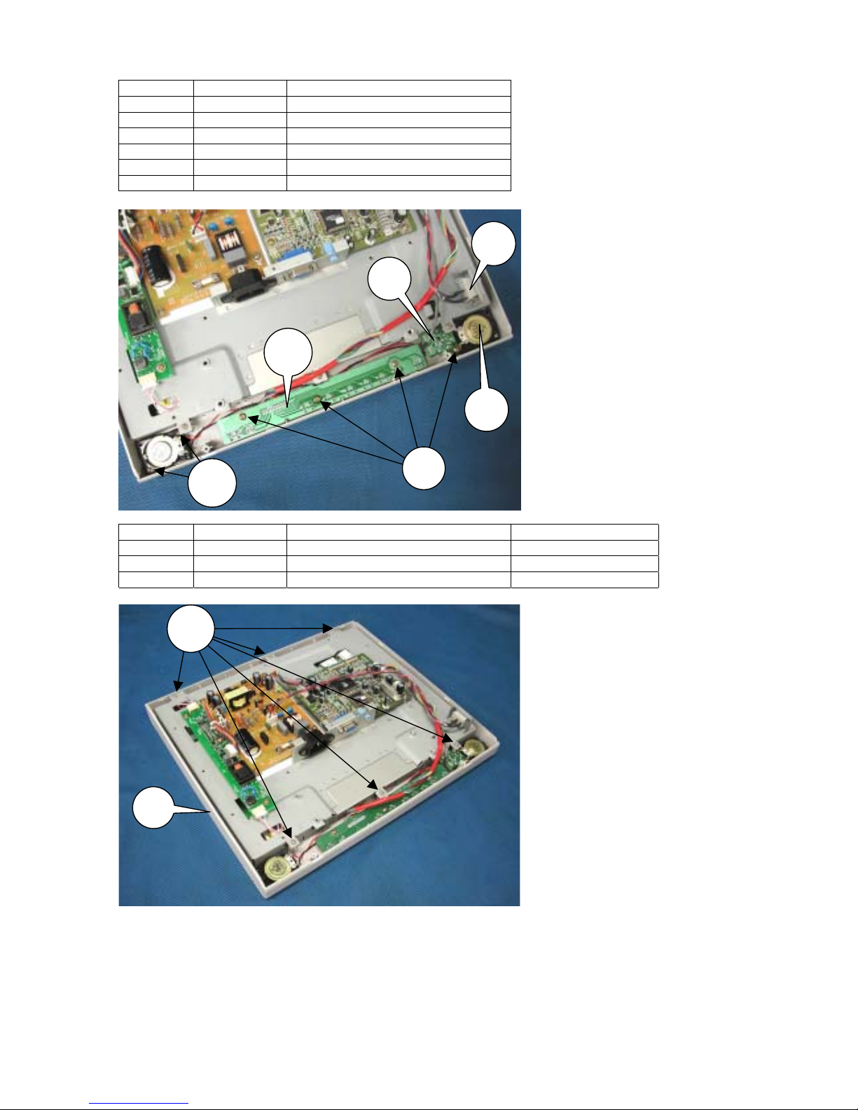
3-5
SYMBOL CODE DESCRIPTION
20 79PL1819 FUNCTION KEY BD-NEC-FA150
21 79PL1901 HEAD PHONE BD-NEC-F A15AA
22 --- SCREW-M3*8
23 79PL1464 SPEAKER 4P N13AA12PCH22 J
24 --- SCREW-M2.6*10
25 79PL1462 SW POWER HF606A1GGATA HUA
SYMBOL CODE DESCRIPTION CABINET COLOR
26 --- SCREW-M3*12
27 79PL2041 FRONT COVER ASS’Y-NMV-NEC White
27 79PL2042 FRONT COVER ASS’Y-NEC-NEC Black
20
21
23
24
22
25
27
26

3-6
SYMBOL CODE DESCRIPTION
28 --- SCREW-M3*5
29 --- BRACKET CHASSIS BASE ASS'Y
30 79PL2039 LCD-15-CLAA150XG01-CPT”
31 79PL2036 HARNESS-FFC-45P(0.5)-95/1
32 79PL2037 HARNESS-FFC-30P(0.5)-115/
31
32
30
29
28
28

3-7
SYMBOL CODE DESCRIPTION CABINET COLOR
33 79PL1905 HINGE-L-NEC-NEC-FA150ATUA
34 79PL1906 HINGE-R-NEC-NEC-FA150ATUA
35 79PL1835 STAND FRONT White
35 79PL1845 COVER-STAND FRONT-NMV(NEC Black
36 --- SCREW-M4*8(SPECAL)
SYMBOL CODE DESCRIPTION CABINET COLOR
37 79PL1898 STAND-BASE-NMV-NEC-FA15AA White
37 79PL2040 BASE ASS’Y-NEC-NEC-FA15AA Black
38 79PL1907 BRACKET-HINGE-NEC-FA150AT
39 --- SCREW-M4*16(DOUBLE WASHER)
33
34
35
36
37
38
39

3-8
SYMBOL CODE DESCRIPTION
40 79PL1875 BRACKET-STAND PLATE-NEC41 79PL1869 FOOT RUBBER
42 --- SCREW-M3*10
40
42
41

4-1
ADJUSTMENT PROCEDURES
TABLE OF CONTENS
Page
1.
Application ------------------------------------------------------------------------------------------------------------- 4-2
2.
Basic operation-------------------------------------------------------------------------------------------------------- 4-2
2.1. General conditions --------------------------------------------------------------------------------------------------- 4-2
2.2. Basic function --------------------------------------------------------------------------------------------------------- 4-2
2.2.1. Key layout ----------------------------------------------------------------------------------------------------------- 4-2
2.2.2. Aging ----------------------------------------------------------------------------------------------------------------- 4-2
2.2.3. Service mode------------------------------------------------------------------------------------------------------- 4-3
3.
Set adjustments------------------------------------------------------------------------------------------------------- 4-4
3.1. Measuring instruments to be used ------------------------------------------------------------------------------- 4-4
3.2. Power source voltage ----------------------------------------------------------------------------------------------- 4-4
3.3. Electrification ---------------------------------------------------------------------------------------------------------- 4-4
3.4. Input signals ----------------------------------------------------------------------------------------------------------- 4-4
3.5. POWER ON and signal input-------------------------------------------------------------------------------------- 4-4
3.6. Manual adjustments ------------------------------------------------------------------------------------------------- 4-5
3.6.1. Input video signal-------------------------------------------------------------------------------------------------- 4-5
3.6.2. VIDEO gain adjustments ---------------------------------------------------------------------------------------- 4-6
3.6.3. Factory setting--------------------------------------------------------------------------------------------------------4-7

4-2
1. Application
This specification shall be applied to the adjustment of the LCD1550ME set.
2. Basic operation
2.1. General conditions
Unless otherwise specified, adjustments shall be carried out under the following conditions:
1) Power source voltage: AC 100 - 120V/ 220 - 240V ± 5%, 50/60Hz
2) Equipment to be used: Equipment that can generate an output of the adjusted VG-819 unit or equivalent
3) Connections: Connections are made to the D-Sub connector of the unit under inspection by means of the
connector that can carry each output of the VG-819.
2.2. Basic function
2.2.1. Key layout
Exit : Menu Close, Sub menu exit
Control : Menu Open, Cursor Move, Item Select
Adjust : Menu Open, Adjust select item, Enter Sub menu
Next : Menu Open, Tag Select, Function execute
Reset : Open reset menu, Sound Mute
2.2.2. Aging
Prior to the adjustment of this model, 30 minutes of aging shall be carried out. The method of aging mode
setting shall conform to the following:
1) Turn the POWER switch on while there are no inputs of the VIDEO and SYNC signals.
2) Press the (4) RIGHT or(3) LEFT or (+) PLUS or (-) MINUS key to display the information OSM.
3) Then, Press the (+) PLUS and (-) MINUS keys simultaneously with the RESET key kept pressed. Then
the mode moves to the aging mode.
Push (+) PLUS and (-) MINUS and RESET
EXIT wCONTROL8 −ADJUST+ NEXT RESET/MUTE

4-3
4) If there is no particular operation, an all white screen (255/255 gradation) is displayed.
5) Operate the(4) RIGHT and (3)LEFT keys in this state. Then, operation for the gradation becomes
possible. It is also possible to change the pattern by operating the (4)RIGHT and (3)LEFT keys.
6) When withdrawing from the aging mode, press the EXIT key.
During operation in the aging mode, the power save mode is not assumed. The LED maintains the green
display.
2.2.3. Service mode
At the time of adjustment of this model, a suggestion may be given to enter the service (factory) mode. This
will be explained below.
(1) Service mode:
1) In the “display mode” menu, press the (+) and (−) LEFT keys at the same time while pressing the
RESET key.
2) When the NEXT key is pressed under the condition that the WARNING screen is displayed, the mode
moves to the SERVICE mode. At that time, the LED is kept lit in green. The OSM AUTO-OFF function
is disabled.
3) When withdrawing from the SERVICE mode, press the EXIT key in the highest hierarchy of the
SERVICE menu, or make a signal changeover, or take an action of POWER OFF.
(2) Service menu:
This is an OSM menu to be displayed when the mode is changed over to the SERVICE mode. The
conditions differ in each mode, in regard to entering and withdrawal, and whether the data are recorded
in the EEPROM. Items of the service menu are used in common.
Push (+) PLUS and (-) MINUS and RESET

4-4
3. Set adjustments
3.1. Measuring instruments to be used
The measuring instruments considered necessary for the adjustment of the LCD1550ME set are specified
below.
1) Equipment that can generate an output of the adjusted VG-819 unit or equivalent
3.2. Power source voltage
100 - 120V/ 220 - 240V ± 5%, 50/60Hz
3.3. Electrification
1) Make connections according to the mode intended for VG-819 cable setting.
2) Turn on the POWER switch of the VG-819 unit.
3) Connect an AC power cable to the unit under inspection.
4) Confirm that the vacation switch (seesaw switch) at the left side of the unit being inspected has been
moved to the “I” side, and turn the POWER switch ON at the right side of the front.
5) The LED of the unit under inspection is lit in amber. (In the middle of signal discrimination)
6) After the completion of signal discrimination, the LED is lit in green.
Note 1: When the POWER source switch is turned on for the first time, the initialization of EEPROM is
effected regardless of the ON/OFF position of the POWER switch. In this period (about 1
minutes), the POWER switch must not be moved to the ON or OFF position. Upon the
completion of the initialization, a normal screen is displayed. (If no signal input is entered, the
information OSM is displayed.) If the screen is not displayed for more than 5 minutes after the
electrification, however, this seems to have resulted from failure in the initialization of EEPROM.
Such a condition is regarded as NG.
Note 2: Connections for the connectors should be carried out always under the condition that the AC
POWER cord plug has been pulled out.
3.4. Input signals
Refer to Paragraph 3.6.1 for each adjustment item.
3.5. POWER ON and signal input
1) Turn on the vacation switch located on the side of the main unit (the power supply for the signal
generator turned off) and turn on the power circuit by pressing the POWER key on the front panel.
Confirm in this case that the LED is lit in amber. When the power supply is turned on for the first time
after the completion of PWB assembly, do not turn off the power supply for at least 10 seconds because
initialization is required to be performed.
2) Turn on the power supply of the signal generator and enter an input of Signal 1. Confirm that the LED is
turned from amber to green.
* If this LED is not lit in green at that time, it is regarded as a defective LED.
3) Prior to adjustments, execute the factory reset procedure without fail. The method of this action is
described below.
a) Display the SERVICE menu and adjust the cursor to the item of [FACTORY RESET].
b) Enter a signal 2 input of VGA 640x480(Solid all white pattern).
c) Press the (+) PLUS or (-) MINUS keys to execute the factory reset procedure.

4-5
3.6. Manual adjustments
3.6.1. Input video signal
VG-819 setting values
MODE Signal 1
VESA 1024x768@75Hz
Signal 2
VGA 640x480
H DOT CLOCK
TOTAL
DISP
SYNC PULSE
BACK
HDstrat
Hdwidth
[MHz]
[DOT]
[DOT]
[DOT]
[DOT]
[DOT]
[DOT]
78.75
1312
1024
96
176
0
0
25.18
800
640
96
48
0
0
V INTERLACE
TOTAL
DISP
SYNC PULSE
BACK PORCH
EQPfp
EQPbp
SERRATION
EDP
VDs
VBf
[H]
[H]
[H]
[H]
[H]
[H]
[H]
[H]
[H]
[H]
NON
800
768
3
28
0
0
OFF
OFF
0
0
NON
525
480
2
33
0
0
OFF
OFF
0
0
OUTPUT OUTPUT MODE
NRZ/RZ
CV
HS
VS
CS
HD
VD
RGB
HT
C
VIDEO
Set-up
Sync
ANALOG
NRZ
POS
POS
NEG
NEG
NEG
POS
POS
POS
0.70
OFF
0.3
ANALOG
NRZ
NEG
NEG
NEG
NEG
NEG
POS
POS
POS
0.70
OFF
0.3
Display setting Gray scale + External frame
(16 gradations)
0 ~ 100%
Solid all white

4-6
3.6.2. VIDEO gain adjustments
Use the signal source for which the analog output (R/G/B) has been adjusted to 0.7V.
1) Enter a signal 1 input of SXGA 1024x768(75Hz).
2) Turn off the display pattern completely and obtain an all black screen.
3) Assume the FACTORY mode in the procedures of Paragraph 2.2.3 and display the SERVICE menu.
4) Press the NEXT key once and advance to the tag [2].
5) Adjust the display pattern to Gray Scale (0 to 100%: in 16 gradations) + External Frame.
6) Use the (4) RIGHT or (3) LEFT keys and adjust the cursor to [AUTO OFFSET]. Make adjustments by
pressing the (+) PLUS or (-) MINUS keys.
7) When adjustments are over and the original screen has been recovered, confirm that all the 16
gradations of black to white are displayed.
8) Use the (4) RIGHT or (3) LEFT keys and adjust the cursor to [AUTO CONT MAX].
9) Press the EXIT key and withdraw from the SERVICE mode.

4-7
3.6.3. Factory setting
1) Enter a signal input. (no prescribe)
2) Assume the FACTORY mode in the procedures of Paragraph 2.2.3 and display the SERVICE menu.
3) Press the NEXT key three times and advance to the tag |4|.
4) Use the (4) RIGHT or (3) LEFT keys and adjust the cursor to [OSD DESIGN],[OSM SELECT] and
[URL]. Set by pressing the (+) PLUS or (-) MINUS keys.
OSD DESIGN 0
OSM SELECT 0
URL 1
5) Press the EXIT key and withdraw from the SERVICE mode.

5-1
INSPECTION
TABLE OF CONTENS
Page
1.
Set Inspection----------------------------------------------------------------------------------------------------- 5-2
1.1.1. Application ----------------------------------------------------------------------------------------------------------- 5-2
1.2. Inspection conditions --------------------------------------------------------------------------------------------- 5-2
1.2.1. Power source voltage --------------------------------------------------------------------------------------------- 5-2
1.2.2. Equipment to be used--------------------------------------------------------------------------------------------- 5-2
1.2.3. Inspection cables/connections---------------------------------------------------------------------------------- 5-2
1.2.4. Brightness setting -------------------------------------------------------------------------------------------------- 5-2
1.2.5. Inspection mode---------------------------------------------------------------------------------------------------- 5-2
1.2.6. OSM functions ------------------------------------------------------------------------------------------------------ 5-2
1.2.7. Configuration of inspection jigs --------------------------------------------------------------------------------- 5-2
1.2.8. Inspection mode setting ------------------------------------------------------------------------------------------ 5-3
1.3. OSM control operation ------------------------------------------------------------------------------------------5-12
1.3.1. Switch functions ---------------------------------------------------------------------------------------------------5-12
1.3.2. Basic operational procedures ----------------------------------------------------------------------------------5-12
1.4. Power ON ----------------------------------------------------------------------------------------------------------5-13
1.5. Inspection ----------------------------------------------------------------------------------------------------------5-13
1.5.1. Inspection on LCD brightness and contrast ----------------------------------------------------------------5-13
1.5.2. Inspection on automatic adjustment function---------------------------------------------------------------5-14
1.5.3. Inspection on input signal identification----------------------------------------------------------------------5-15
1.5.4. Inspection on Audio function -----------------------------------------------------------------------------------5-16
1.6.
Setting before shipment-----------------------------------------------------------------------------------------5-17
1.7. Safety test ----------------------------------------------------------------------------------------------------------5-17
1.7.1. Input current measurements -----------------------------------------------------------------------------------5-17
1.7.2. Power source/earth connections ------------------------------------------------------------------------------5-18
1.7.3. Dielectric strength test -------------------------------------------------------------------------------------------5-18
1.7.4. Leakage current test----------------------------------------------------------------------------------------------5-19
1.7.5. Insulation resistance test----------------------------------------------------------------------------------------5-19
2.
External inspection on the LCD module --------------------------------------------------------------------5-20
2.1. External inspection of the display surface------------------------------------------------------------------5-20
2.1.1. Inspection items ---------------------------------------------------------------------------------------------------5-20
2.1.2. Inspection standards ---------------------------------------------------------------------------------------------5-20
3.
Inspection of PLUG & PLAY communication and OSM "MONITOR INFORMATION" for
model name/ serial number ------------------------------------------------------------------------------------5-22
3.1. A construction of System ---------------------------------------------------------------------------------------5-22
3.2. Input Signal --------------------------------------------------------------------------------------------------------5-22
3.3. Operational procedures-----------------------------------------------------------------------------------------5-23
3.4. EDID data file------------------------------------------------------------------------------------------------------5-24

5-2
1. Set Inspection
1.1.1. Application
The inspection procedures specified in this item shall be applied to the inspection of the LCD1550ME unit.
1.2. Inspection conditions
Unless otherwise specified, inspection shall be carried out under the following conditions.
1.2.1. Power source voltage
AC voltage: AC 100 - 120V/ 220 - 240V ± 5%, 50/60Hz
1.2.2. Equipment to be used
Equipment that can generate an output of the adjusted VG-819 unit or equivalent.
The signal timing for the inspection ROM shall conform to the table provided in Paragraph 1.2.8 herein.
1.2.3. Inspection cables/connections
1) Connections between the unit under inspection and the VG-819 shall be made through D-SUB
connector of the unit under inspection and the cable that can carry each output of the VG-819, as
specified below.
BNC-DSUB (female) connector
2) For connections to the power supply, an AC cable for LCD1550VM shall be used.
1.2.4. Brightness setting
Unless otherwise specified, inspection shall be carried out under the condition that the LCD brightness is
set at the highest level.
1.2.5. Inspection mode
Each inspection shall be carried out in the inspection mode specified in each relevant inspection item.
The detailed setting for each mode shall be specified in Paragraph 1.2.8 herein.
1.2.6. OSM functions
If checking and operation by OSM are specified in each inspection item, display and operation of the
OSM shall be carried out by operating the push switches of the unit under inspection, according to the
instructions.
Outline operation is described in Item 1.3, “Operation of OSM control.”
1.2.7. Configuration of inspection jigs
Signal source
1) A video signal generator shall be used, which can generate an output of the VG-819 unit or
equivalent.
5-3
1.2.8. Inspection mode setting
The respective setting data shall be the data for the VG-819.
Signal VG-819 setting values
Mode 01 02 03
Not used
04 05
H CLOCK
HPERIOD
HDISP
HSYNC
HBACKP
HDSTART
HDWIDTH
[MHz]
[DOT]
[DOT]
[DOT]
[DOT]
[DOT]
[DOT]
28.322
900
720
108
54
0
0
35.500
936
720
72
108
0
0
21.053
848
640
64
84
0
0
28.322
900
720
108
54
0
0
35.500
936
720
72
108
0
0
V VTOTAL
VDISP
VSYNC
VBACKP
EQP FP
EQP BP
SERRATION
EQP
VDSTART
VDLINE
SCAN
[H]
[H]
[H]
[H]
[H]
[H]
[H]
[H]
449
350
2
60
0
0
OFF
OFF
0
0
Nonint
446
350
3
61
0
0
OFF
OFF
0
0
Nonint
440
400
8
25
0
0
OFF
OFF
0
0
Nonint
449
400
2
35
0
0
OFF
OFF
0
0
Nonint
446
400
3
42
0
0
OFF
OFF
0
0
Nonint
OUTPUT NRZ/RZ
HS
VS
CS
HD
VD
CLOCK
SYNC ON
RGB
VIDEO
SETUP
CLKMODE
CLKOUT
DISP,1CH,2CH
SW0,SW1
RGB
R(7-0),G(7-0),B(7-0)
DELAY
CLOCK DELAY
NRZ
POSI
NEGA
NEGA
NEGA
NEGA
NEGA
POSI
0.70V
OFF
1/2
ALL
POSI
OFF
8 bit
11111111
ON
4 nsec
NRZ
POSI
NEGA
NEGA
NEGA
NEGA
NEGA
POSI
0.70V
OFF
1/2
ALL
POSI
OFF
8 bit
11111111
ON
4 nsec
NRZ
NEGA
NEGA
NEGA
NEGA
NEGA
NEGA
POSI
0.70V
OFF
1/2
ALL
POSI
OFF
8 bit
11111111
ON
4 nsec
NRZ
NEGA
POSI
NEGA
NEGA
NEGA
NEGA
POSI
0.70V
OFF
1/2
ALL
POSI
OFF
8 bit
11111111
ON
4 nsec
NRZ
NEGA
POSI
NEGA
NEGA
NEGA
NEGA
POSI
0.70V
OFF
1/2
ALL
POSI
OFF
8 bit
11111111
ON
4 nsec
PAT SEL OPTION 2 OPTION 2 OPTION 2 OPTION 2 OPTION 2
CHRA
PATTERN
Format
Code
Font
Cell
1
82
16*16
16*16
1
82
16*16
16*16
1
82
16*16
16*16
1
82
16*16
16*16
1
82
16*16
16*16
GRAY Direction : 0 L0: 0
L7: 127
LE: 239
L1: 17
L8: 143
LF: 255
L2: 34
L9: 159
L3: 51
LA: 175
L4: 68
LB: 191
L5: 85
LC: 207
L6: 102
LD: 223
OPTION 2 (Note 2)

5-4
Signal VG-819 setting values
Mode 06 07 08 09 10
H CLOCK
HPERIOD
HDISP
HSYNC
HBACKP
HDSTART
HDWIDTH
[MHz]
[DOT]
[DOT]
[DOT]
[DOT]
[DOT]
[DOT]
25.18
800
640
96
48
0
0
30.24
864
640
64
96
0
0
31.5
832
640
40
128
0
0
31.5
840
640
64
120
0
0
36.0
832
640
56
80
0
0
V VTOTAL
VDISP
VSYNC
VBACKP
EQP FP
EQP BP
SERRATION
EQP
VDSTART
VDLINE
SCAN
[H]
[H]
[H]
[H]
[H]
[H]
[H]
[H]
525
480
2
33
0
0
OFF
OFF
0
0
Nonint
525
480
3
39
0
0
OFF
OFF
0
0
Nonint
520
480
3
28
0
0
OFF
OFF
0
0
Nonint
500
480
3
16
0
0
OFF
OFF
0
0
Nonint
509
480
3
25
0
0
OFF
OFF
0
0
Nonint
OUTPUT NRZ/RZ
HS
VS
CS
HD
VD
CLOCK
SYNC ON
RGB
VIDEO
SETUP
CLKMODE
CLKOUT
DISP,1CH,2CH
SW0,SW1
RGB
R(7-0),G(7-0),B(7-0)
DELAY
CLOCK DELAY
NRZ
NEGA
NEGA
NEGA
NEGA
NEGA
NEGA
POSI
0.70V
OFF
1/2
ALL
POSI
OFF
8 bit
11111111
ON
4 nsec
NRZ
NEGA
NEGA
NEGA
NEGA
NEGA
NEGA
G
POSI
0.70V
OFF
1/2
ALL
POSI
OFF
8 bit
11111111
ON
4 nsec
NRZ
NEGA
NEGA
NEGA
NEGA
NEGA
NEGA
POSI
0.70V
OFF
1/2
ALL
POSI
OFF
8 bit
11111111
ON
4 nsec
NRZ
NEGA
NEGA
NEGA
NEGA
NEGA
NEGA
POSI
0.70V
OFF
1/2
ALL
POSI
OFF
8 bit
11111111
ON
4 nsec
NRZ
NEGA
NEGA
NEGA
NEGA
NEGA
NEGA
POSI
0.70V
OFF
1/2
ALL
POSI
OFF
8 bit
11111111
ON
4 nsec
PAT SEL OPTION 2 OPTION 2 OPTION 2 OPTION 2 OPTION 2
CHRA
PATTERN
Format
Code
Font
Cell
1
82
16*16
16*16
1
82
16*16
16*16
1
82
16*16
16*16
1
82
16*16
16*16
1
82
16*16
16*16
GRAY Direction : 0 L0: 0
L7: 127
LE: 239
L1: 17
L8: 143
LF: 255
L2: 34
L9: 159
L3: 51
LA: 175
L4: 68
LB: 191
L5: 85
LC: 207
L6: 102
LD: 223
OPTION 2 (Note 2)

5-5
Signal VG-819 setting values
Mode 11 12 13 14 15
H CLOCK
HPERIOD
HDISP
HSYNC
HBACKP
HDSTART
HDWIDTH
[MHz]
[DOT]
[DOT]
[DOT]
[DOT]
[DOT]
[DOT]
36.0
1024
800
72
128
0
0
40.0
1056
800
128
88
0
0
49.5
1056
800
80
160
0
0
50.0
1040
800
120
64
0
0
56.25
1048
800
64
152
0
0
V VTOTAL
VDISP
VSYNC
VBACKP
EQP FP
EQP BP
SERRATION
EQP
VDSTART
VDLINE
SCAN
[H]
[H]
[H]
[H]
[H]
[H]
[H]
[H]
625
600
2
22
0
0
OFF
OFF
0
0
Nonint
628
600
4
23
0
0
OFF
OFF
0
0
Nonint
625
600
3
21
0
0
OFF
OFF
0
0
Nonint
666
600
6
23
0
0
OFF
OFF
0
0
Nonint
631
600
3
27
0
0
OFF
OFF
0
0
Nonint
OUTPUT NRZ/RZ
HS
VS
CS
HD
VD
CLOCK
SYNC ON
RGB
VIDEO
SETUP
CLKMODE
CLKOUT
DISP,1CH,2CH
SW0,SW1
RGB
R(7-0),G(7-0),B(7-0)
DELAY
CLOCK DELAY
NRZ
POSI
POSI
NEGA
NEGA
NEGA
NEGA
POSI
0.70V
OFF
1/2
ALL
POSI
OFF
8 bit
11111111
ON
4 nsec
NRZ
POSI
POSI
NEGA
NEGA
NEGA
NEGA
POSI
0.70V
OFF
1/2
ALL
POSI
OFF
8 bit
11111111
ON
4 nsec
NRZ
POSI
POSI
NEGA
NEGA
NEGA
NEGA
POSI
0.70V
OFF
1/2
ALL
POSI
OFF
8 bit
11111111
ON
4 nsec
NRZ
POSI
POSI
NEGA
NEGA
NEGA
NEGA
POSI
0.70V
OFF
1/2
ALL
POSI
OFF
8 bit
11111111
ON
4 nsec
NRZ
POSI
POSI
NEGA
NEGA
NEGA
NEGA
POSI
0.70V
OFF
1/2
ALL
POSI
OFF
8 bit
11111111
ON
4 nsec
PAT SEL OPTION 2 OPTION 2 OPTION 2 OPTION 2 OPTION 2
CHRA
PATTERN
Format
Code
Font
Cell
1
82
16*16
16*16
1
82
16*16
16*16
1
82
16*16
16*16
1
82
16*16
16*16
1
82
16*16
16*16
GRAY Direction : 0 L0:0
L7:127
LE:239
L1:17
L8:143
LF:255
L2:34
L9:159
L3:51
LA:175
L4:68
LB:191
L5:85
LC:207
L6:102
LD:223
OPTION 2 (Note 2)

5-6
Signal VG-819 setting values
Mode 16 17 18 19 20
H CLOCK
HPERIOD
HDISP
HSYNC
HBACKP
HDSTART
HDWIDTH
[MHz]
[DOT]
[DOT]
[DOT]
[DOT]
[DOT]
[DOT]
57.28
1152
832
64
224
0
0
65.0
1344
1024
136
160
0
0
70.49
1344
1024
136
160
0
0
75.0
1328
1024
136
144
0
0
78.75
1312
1024
96
176
0
0
V VTOTAL
VDISP
VSYNC
VBACKP
EQP FP
EQP BP
SERRATION
EQP
VDSTART
VDLINE
SCAN
[H]
[H]
[H]
[H]
[H]
[H]
[H]
[H]
667
624
3
39
0
0
OFF
OFF
0
0
Nonint
806
768
6
29
0
0
OFF
OFF
0
0
Nonint
806
768
6
29
0
0
OFF
OFF
0
0
Nonint
806
768
6
29
0
0
OFF
OFF
0
0
Nonint
800
768
3
28
0
0
OFF
OFF
0
0
Nonint
OUTPUT NRZ/RZ
HS
VS
CS
HD
VD
CLOCK
SYNC ON
RGB
VIDEO
SETUP
CLKMODE
CLKOUT
DISP,1CH,2CH
SW0,SW1
RGB
R(7-0),G(7-0),B(7-0)
DELAY
CLOCK DELAY
NRZ
NEGA
NEGA
POSI
POSI
POSI
POSI
G
POSI
0.70V
OFF
1/2
ALL
POSI
OFF
8 bit
11111111
ON
4 nsec
NRZ
NEGA
NEGA
NEGA
NEGA
NEGA
NEGA
POSI
0.70V
OFF
1/2
ALL
POSI
OFF
8 bit
11111111
ON
4 nsec
NRZ
NEGA
NEGA
NEGA
NEGA
NEGA
NEGA
POSI
0.70V
OFF
1/2
ALL
POSI
OFF
8 bit
11111111
ON
4 nsec
NRZ
NEGA
NEGA
NEGA
NEGA
NEGA
NEGA
POSI
0.70V
OFF
1/2
ALL
POSI
OFF
8 bit
11111111
ON
4 nsec
NRZ
POSI
POSI
NEGA
NEGA
NEGA
NEGA
G
POSI
0.70V
OFF
1/2
ALL
POSI
OFF
8 bit
11111111
ON
4 nsec
PAT SEL OPTION 2 OPTION 2 OPTION 2 OPTION 2 OPTION 2
CHRA
PATTERN
Format
Code
Font
Cell
1
82
16*16
16*16
1
82
16*16
16*16
1
82
16*16
16*16
1
82
16*16
16*16
1
82
16*16
16*16
GRAY Direction : 0 L0:0
L7:127
LE:239
L1:17
L8:143
LF:255
L2:34
L9:159
L3:51
LA:175
L4:68
LB:191
L5:85
LC:207
L6:102
LD:223
OPTION 2 (Note 2)

5-7
Signal VG-819 setting values
Mode 21 22 23 24 25
Not used
H CLOCK
HPERIOD
HDISP
HSYNC
HBACKP
HDSTART
HDWIDTH
[MHz]
[DOT]
[DOT]
[DOT]
[DOT]
[DOT]
[DOT]
94.5
1376
1024
96
208
0
0
94.50
1528
1152
128
208
0
0
108.00
1800
1280
112
312
0
0
126.00
1680
1280
144
224
0
0
107.50
1664
1280
192
160
0
0
V VTOTAL
VDISP
VSYNC
VBACKP
EQP FP
EQP BP
SERRATION
EQP
VDSTART
VDLINE
SCAN
[H]
[H]
[H]
[H]
[H]
[H]
[H]
[H]
808
768
3
36
0
0
OFF
OFF
0
0
Nonint
937
900
4
31
0
0
OFF
OFF
0
0
Nonint
1000
960
3
36
0
0
OFF
OFF
0
0
Nonint
1000
960
3
36
0
0
OFF
OFF
0
0
Nonint
1078
1024
4
43
0
0
OFF
OFF
0
0
Nonint
OUTPUT NRZ/RZ
HS
VS
CS
HD
VD
CLOCK
SYNC ON
RGB
VIDEO
SETUP
CLKMODE
CLKOUT
DISP,1CH,2CH
SW0,SW1
RGB
R(7-0),G(7-0),B(7-0)
DELAY
CLOCK DELAY
NRZ
POSI
POSI
NEGA
NEGA
NEGA
NEGA
POSI
0.70V
OFF
1/2
ALL
POSI
OFF
8 bit
11111111
ON
4 nsec
NRZ
POSI
POSI
NEGA
NEGA
NEGA
NEGA
POSI
0.70V
OFF
1/2
ALL
POSI
OFF
8 bit
11111111
ON
4 nsec
NRZ
POSI
POSI
NEGA
NEGA
NEGA
NEGA
POSI
0.70V
OFF
1/2
ALL
POSI
OFF
8 bit
11111111
ON
4 nsec
NRZ
NEGA
NEGA
NEGA
NEGA
NEGA
NEGA
POSI
0.70V
OFF
1/2
ALL
POSI
OFF
8 bit
11111111
ON
4 nsec
NRZ
POSI
POSI
NEGA
NEGA
NEGA
NEGA
POSI
0.70V
OFF
1/2
ALL
POSI
OFF
8 bit
11111111
ON
4 nsec
PAT SEL OPTION 2 OPTION 2 OPTION 2 OPTION 2 OPTION 2
CHRA
PATTERN
Format
Code
Font
Cell
1
82
16*16
16*16
1
82
16*16
16*16
1
82
16*16
16*16
1
82
16*16
16*16
1
82
16*16
16*16
GRAY Direction : 0 L0:0
L7:127
LE:239
L1:17
L8:143
LF:255
L2:34
L9:159
L3:51
LA:175
L4:68
LB:191
L5:85
LC:207
L6:102
LD:223
OPTION 2 (Note 2)

5-8
Signal VG-819 setting values
Mode 26 27 28 29 30
H CLOCK
HPERIOD
HDISP
HSYNC
HBACKP
HDSTART
HDWIDTH
[MHz]
[DOT]
[DOT]
[DOT]
[DOT]
[DOT]
[DOT]
108.00
1688
1280
112
248
0
0
117.00
1632
1280
112
224
0
0
135.00
1688
1280
144
248
0
0
135.00
1664
1280
64
288
0
0
94.50
1480
1152
96
200
0
0
V VTOTAL
VDISP
VSYNC
VBACKP
EQP FP
EQP BP
SERRATION
EQP
VDSTART
VDLINE
SCAN
[H]
[H]
[H]
[H]
[H]
[H]
[H]
[H]
1066
1024
3
38
0
0
OFF
OFF
0
0
Nonint
1067
1024
8
33
0
0
OFF
OFF
0
0
Nonint
1066
1024
3
38
0
0
OFF
OFF
0
0
Nonint
1066
1024
8
32
0
0
OFF
OFF
0
0
Nonint
912
864
3
44
0
0
OFF
OFF
0
0
Nonint
OUTPUT NRZ/RZ
HS
VS
CS
HD
VD
CLOCK
SYNC ON
RGB
VIDEO
SETUP
CLKMODE
CLKOUT
DISP,1CH,2CH
SW0,SW1
RGB
R(7-0),G(7-0),B(7-0)
DELAY
CLOCK DELAY
NRZ
POSI
POSI
NEGA
NEGA
NEGA
NEGA
POSI
0.70V
OFF
1/2
ALL
POSI
OFF
8 bit
11111111
ON
4 nsec
NRZ
POSI
POSI
NEGA
NEGA
NEGA
NEGA
POSI
0.70V
OFF
1/2
ALL
POSI
OFF
8 bit
11111111
ON
4 nsec
NRZ
POSI
POSI
POSI
NEGA
NEGA
NEGA
POSI
0.70V
OFF
1/2
ALL
POSI
OFF
8 bit
11111111
ON
4 nsec
NRZ
POSI
POSI
POSI
NEGA
NEGA
NEGA
POSI
0.70V
OFF
1/2
ALL
POSI
OFF
8 bit
11111111
ON
4 nsec
NRZ
POSI
POSI
POSI
NEGA
NEGA
NEGA
POSI
0.70V
OFF
1/2
ALL
POSI
OFF
8 bit
11111111
ON
4 nsec
PAT SEL OPTION 2 OPTION 2 OPTION 2 OPTION 2 OPTION 2
CHRA
PATTERN
Format
Code
Font
Cell
1
82
16*16
16*16
1
82
16*16
16*16
1
82
16*16
16*16
1
82
16*16
16*16
1
82
16*16
16*16
GRAY Direction : 0 L0:0
L7:127
LE:239
L1:17
L8:143
LF:255
L2:34
L9:159
L3:51
LA:175
L4:68
LB:191
L5:85
LC:207
L6:102
LD:223
OPTION 2 (Note 2)

5-9
Signal VG-819 setting values
Mode 31 32 33 34 35
H CLOCK
HPERIOD
HDISP
HSYNC
HBACKP
HDSTART
HDWIDTH
[MHz]
[DOT]
[DOT]
[DOT]
[DOT]
[DOT]
[DOT]
108.00
1600
1152
128
256
0
0
162.00
2160
1600
192
304
0
0
108.00
1688
1280
112
248
0
0
V VTOTAL
VDISP
VSYNC
VBACKP
EQP FP
EQP BP
SERRATION
EQP
VDSTART
VDLINE
SCAN
[H]
[H]
[H]
[H]
[H]
[H]
[H]
[H]
900
864
3
32
0
0
OFF
OFF
0
0
Nonint
1250
1200
3
46
0
0
OFF
OFF
0
0
Nonint
1066
1024
3
6380
0
0
OFF
OFF
0
0
Nonint
OUTPUT NRZ/RZ
HS
VS
CS
HD
VD
CLOCK
SYNC ON
RGB
VIDEO
SETUP
CLKMODE
CLKOUT
DISP,1CH,2CH
SW0,SW1
RGB
R(7-0),G(7-0),B(7-0)
DELAY
CLOCK DELAY
NRZ
POSI
POSI
POSI
NEGA
NEGA
NEGA
POSI
0.70V
OFF
1/2
ALL
POSI
OFF
8 bit
11111111
ON
4 nsec
NRZ
POSI
POSI
POSI
NEGA
NEGA
NEGA
POSI
0.70V
OFF
1/2
ALL
POSI
OFF
8 bit
11111111
ON
4 nsec
NRZ
POSI
POSI
NEGA
NEGA
NEGA
NEGA
POSI
0.70V
OFF
1/2
ALL
POSI
OFF
8 bit
11111111
ON
4 nsec
PAT SEL OPTION 2 OPTION 2 OPTION 2
CHRA
PATTERN
Format
Code
Font
Cell
1
82
16*16
16*16
1
82
16*16
16*16
1
82
16*16
16*16
GRAY Direction : 0 L0:0
L7:127
LE:239
L1:17
L8:143
LF:255
L2:34
L9:159
L3:51
LA:175
L4:68
LB:191
L5:85
LC:207
L6:102
LD:223
OPTION 2 (Note 2)

5-10
Signal VG-819 setting values
Mode 36 37 38 39 40
H CLOCK
HPERIOD
HDISP
HSYNC
HBACKP
HDSTART
HDWIDTH
[MHz]
[DOT]
[DOT]
[DOT]
[DOT]
[DOT]
[DOT]
34.40
800
640
96
48
0
0
34.40
800
640
96
48
0
0
V VTOTAL
VDISP
VSYNC
VBACKP
EQP FP
EQP BP
SERRATION
EQP
VDSTART
VDLINE
SCAN
[H]
[H]
[H]
[H]
[H]
[H]
[H]
[H]
1024
480
2
33
0
0
OFF
OFF
0
0
Nonint
1024
480
2
33
0
0
OFF
OFF
0
0
Nonint
OUTPUT NRZ/RZ
HS
VS
CS
HD
VD
CLOCK
SYNC ON
RGB
VIDEO
SETUP
CLKMODE
CLKOUT
DISP,1CH,2CH
SW0,SW1
RGB
R(7-0),G(7-0),B(7-0)
DELAY
CLOCK DELAY
NRZ
NEGA
POSI
NEGA
NEGA
POSI
NEGA
POSI
0.70V
OFF
1/2
ALL
POSI
OFF
8 bit
11111111
ON
4 nsec
NRZ
NEGA
NEGA
NEGA
NEGA
POSI
NEGA
POSI
0.70V
OFF
1/2
ALL
POSI
OFF
8 bit
11111111
ON
4 nsec
PAT SEL CHARA
CHARA
CHRA
PATTERN
Format
Code
Font
Cell
1
82
16*16
16*16
1
82
16*16
16*16
GRAY Direction : 0 L0:0
L7:127
LE:239
L1:17
L8:143
LF:255
L2:34
L9:159
L3:51
LA:175
L4:68
LB:191
L5:85
LC:207
L6:102
LD:223

5-11
Note 1:
According to the designation of sync signals and the setting of each inspection mode, the analog outputs
(BNC) of the signal generator shall be connected as specified below. (Except the cases when otherwise
specified)
1) SEPARATE: R/G/B CONNECTION, HS ←→ H, VS ←→ V, CS not connected
Note 2:
Screen of Option 2

5-12
1.3. OSM control operation
Each OSM function is available by pressing the push-button switches (EXIT,3,4, -, +, NEXT, RESET)
allocated in the lower section of the front bezel (or the control PWB when a PWB unit only is furnished).
1.3.1. Switch functions
The basic functions of the respective push-button switches (or called the keys, but in the same meaning)
are described below.
In a mode where no OSM display is presented, the main menu of the OSM menu can be displayed when
any key out of UP, DOWN, -, and + is pressed.
Exit: Menu Close, Sub menu exit
Control (3,4): Menu Open, Cursor Move, Item Select
Adjust (+, -): Menu Open, Adjust select item, Enter Sub menu
Next Menu Open, Tag Select, Function execute
Reset: Open reset menu, Sound Mute
1.3.2. Basic operational procedures
1) Press any key out of 3or4or + or -, and confirm that a menu as shown below is displayed.
2) When the NEXT key is used, the selective tag moves to the right and the adjusting screen changes.
With the adjusting screen selected, use the keys3and4to select the adjusting item (simply “item”
hereafter) and set the adjusting value by the use of the keys - and +. To execute an automatic
adjustment function (CONTRAST AUTO ADJUST, AUTO ADJUST), press the key + or - in the state of
item highlight. Then, auto adjust are carried out.
When the adjusting item is present in TOOL or INFO., move to the selecting item with the NEXT key
and select the wanted item with the keys3and4. In the state that the wanted item is highlighted in
green, press the key + or - in order to get the adjusting screen displayed for each item.
3) When inspection is finished, press the EXIT key to withdraw from the OSM menu.

5-13
1.4. Power ON
1) Connect an AC power cable to the unit being inspected.
2) Connect the VG-819 cable to the unit being inspected. Any input connector is acceptable.
3) Turn on the POWER switch of the VG-819 to generate an output of Signal 17.
4) There is a vacation switch (a seesaw switch) at the left side of the unit being inspected. Confirm that this
switch is set at the “
” side. Press the POWER key at the right end of the front to turn on the unit being
inspected.
5) The LED is then lit in green and a screen is displayed.
1.5. Inspection
1.5.1. Inspection on LCD brightness and contrast
1) Enter Signal 17 through INPUT. The screen display is made in all white.
2) Display the BRIGHTNESS/CONTRAST tag of the OSM menu.
3) Get BRIGHTNESS highlighted with the3and4keys.
Brightness adjust menu
4) Confirm that the green bar is changed by the operation of the (-) and (+) keys, and that the screen
brightness is changed.
5) Confirm that the highlight display is for BRIGHTNESS. Press the RESET key. Then, the confirmation
screen is displayed. Press the NEXT key to make resetting. (The BRIGHTNESS bar is returned fully
to the right.)
6) Use the3and4keys to obtain CONTRAST displayed in the highlight mode.
Contrast adjust menu
7) Confirm that the green bar is changed and the screen contrast is also changed when the (-) and (+)
keys are operated.

5-14
8) Get AUTO ADJUST highlighted with the (-) and (+) keys.
Contrast Auto Adjust menu
9) Press the (-) and (+) keys and wait until the OSM display is restored to the former display. At that time,
confirm that the screen is normally displayed.
1.5.2. Inspection on automatic adjustment function
1) Enter Signal 17 through INPUT. (1-dot loss + External frame screen)
2) Display the OSM menu. Use the NEXT key to move as far as to the POSITION tag.
Horizontal Position adjust menu Vertical Position adjust menu
H.SIZE adjust menu FINE adjust menu
3) Move the cursor to the HORIZONTAL POSITION, using the3and4keys. Operate the (-) and (+) keys
to shift the POSITION to an extent so that the caused difference can be visually perceived.
4) In the same manner, shift the VERTICAL POSITION, H. SIZE, and FINE from their initial levels.
5) Use the NEXT key to move as far as to the AUTO ADJUST adjusting tag.
Auto Adjust menu
6) Execute automatic adjustments by the use of the (+) or (-) key.
Confirm that the screen (POSITION/SIZE/PHASE) is normally adjusted.

5-15
1.5.3. Inspection on input signal identification
Purpose of inspection: Confirming that a normal display is obtainable for each signal input.
Unless otherwise specified, the display pattern is as shown in the initial screen,
conforming to 1.2.8 [Inspection mode setting].
--- Inspection of signal input ---
1) According to the table below, make setting of the input connector and the signal, and enter a signal
input.
Item No. Ins
p
ection signal No. SYNC
1 1 SEPARATE
2 4 SEPARATE
3 6 SEPARATE
4 8 SEPARATE
5 9 SEPARATE
6 11 SEPARATE
7 12 SEPARATE
8 13 SEPARATE
9 14 SEPARATE
10 17 SEPARATE
11 19 SEPARATE
12 20 SEPARATE
2) When a screen is displayed, visually check whether the display is free from abnormality.
(Freedom from any extreme displacement in position, size, and phase, flickering in the screen, and
extreme color deterioration)
3) Check the OSM menu for the signals that have signal numbers underlined. Display the OSM
information screen (the rightmost tag). Get the [DISPLAY MODE] highlighted with the (3) LEFT or (4)
RIGHT keys. Then, display the [DISPLAY MODE] screen with the (+) PLUS or (-) MINUS key. Confirm
that the displayed definition coincides with the definition of the input signal.
--- Inspection of POWER SAVE ---
4) Remove the output signal of the VG-819 from H.sync and V.sync connector. Confirm that the screen
disappears and the OSM menu of the [NO SIGNAL] is displayed. Wait in this state for about 5 seconds,
and confirm that the LED display is turned into amber and the POWER SAVE mode is assumed.

5-16
AUDIO INPUT
PC or Audio Player
1.5.4. Inspection on Audio function
Purpose of inspection: Confirming that the audio function works normally.
1) It connects audio-in with the PC or the audio player and it enters a sound.
2) Enter Signal 17 through INPUT.
3) Display the OSM menu. Use the NEXT key to move as far as to the Volume tag.
Sound Volume menu
4) Confirm that the green bar is changed and the audio volume is also changed when the (-) and (+) keys
are operated.
5) It confirms that sound is outputted from the left-right speakers and headphones.

5-17
1.6. Setting before shipment
In order to recover the initial conditions of all settings, the contents of the memory are reset before
shipment. This reset process involves actions in regard to the memory of signal modes. Therefore, these
actions should be taken after the completion of all electrical inspection and display inspection.
1) Enter an input of Signal 4 through INPUT. Operate the OSM to enter the service mode, and display a
service menu.
2) Adjust the cursor to [FACTORY PRESET] by the use of the(3) LEFT or (4) RIGHT keys, and press the
(+) PLUS, (-) MINUS keys.
Service menu
3) When the OSM is displayed again, the resetting process has been finished. Press the EXIT key to
withdraw from the service mode.
Note 1: After the completion of this process, confirm, without fail, that the present condition is surely after
the withdrawal from the service mode.
1.7. Safety test
• Destination : All over the world
• Applicable standards : UL1950/C-UL/EN60950
• Unit class : Class I units (the units protected against electric shocks by protective
earthing, or those equipped with 3-core power cords)
• Ratings : AC100-120/220-240V 50/60Hz 0.7 / 0.35A
1.7.1. Input current measurements
Under the measuring conditions specified below, an input current shall be measured while the 50Hz input
voltage is maintained at 220V AC (+0 to -5V). The input currents measured shall be confirm so they
satisfy the judgment standard. (The rear rating plates are the same as those for North America and
Europe. Therefore, measurements should also be based on this setting.)
(1) Measuring conditions
• Condition of the set : ON mode
• Measuring conditions : The inspection signal is set at “17” and “white” is displayed throughout
the screen.
At that time, the brightness and contrast shall be kept under the
brightest condition.
(2) Judgment standard
• The input current shall be kept below 0.7A +10%.

5-18
1.7.2. Power source/earth connections
a. Checks on the power source/earth connections
The earth side of the cord or the earth wire of the inlet filter for the cord set shall be visually checked to
see that it is connected to the chassis block of the unit as specified below.
1) The earth wire color shall be spiral of green and yellow.
[Units applicable to UL1950 or IEC60950 (EN60950)]
2) The earth wire shall be firmly connected to the chassis block by the use of a screw (See Note) of
3.5mm∅ in diameter.
Note: Spring washers or star washers shall be used, without fail.
b. Earth resistance testing
This testing shall be carried out prior to the dielectric strength test.
The earth resistance shall be 0.1Ω or less when a current of 25A AC is carried between the earth side of
the cord (the plug block or the section closest to the plug where no plug is provided) and the metallic
block (the DVI connector) that is used as a safety earth for the unit.
Where the earth resistance exceeds 0.1Ω, the condition shall be still acceptable if the earth resistance is
0.1Ω or less when the resistance of the power cord is excepted.
1.7.3. Dielectric strength test
To confirm the freedom from insulation breakdown, testing shall be carried out under the conditions
specified below.
1) Measuring conditions
• Measuring instrument : Dielectric strength tester (The specified voltage shall be maintained in the
state that a current of 10mA is carried.)
• Testing point : Between the electrical circuit block and the exposed metallic block (D-SUB
connector)
Note: The electrical circuit block shall mean the power input block (primary side). Testing shall be carried
out under the condition that both poles of the power plug are short-circuited. (Where a 3-core cord is
used, the two poles other than the earth terminal shall be short-circuited.)
2) Judgment standard
The freedom from insulation breakdown shall be confirmed under the condition that the applied voltage is
maintained at 1500V AC (+0 to 50V) for one minute.
Even though the result of this testing is OK, such a condition shall be regarded as unacceptable if there is
a leakage (flashing) around the section where the test voltage has been applied.
If the result of insulation resistance test is found unacceptable, to be carried out after this testing, such a
condition shall be regarded as that an insulation breakdown has occurred.

5-19
1.7.4. Leakage current test
A leakage current shall be measured under the conditions specified below, in order to confirm that the
requirements of the judgment standard are met.
1) Measuring conditions
• Measuring instrument : Leakage current meter (A 1500Ω resistor shall be incorporated, together
with a bypass capacitor of 0.15µF. )
• Testing point : Between the exposed metallic block (D-SUB connector) and Phases A and
B of the power source.
• Condition of the set : A power cable shall be connected without connecting a signal generator. The
see-saw switch on the set side shall be turned ON and OFF.
2) Judgment standard
The leakage current measured shall be 1.5mA or less with an input of 240V AC × 1.06 +5/-0V (60Hz).
1.7.5. Insulation resistance test
An insulation resistance shall be measured under the conditions specified below, in order to confirm that
the requirements of the judgment standard are met.
(1) Measuring conditions
• Measuring instrument : 500V DC megger
• Testing point : Between the power circuit block and the exposed metallic block
(D-SUBI connector)
• Measured value readout : A test voltage shall be applied for one minute and the resistance value
shall be read out thereafter.
(2) Judgment standard : 10MΩ or more

5-20
2. External inspection on the LCD module
2.1. External inspection of the display surface
The display surface shall be visually inspected according to the inspection items specified below. In cases
of the discovery of extreme defects or doubtful judgment, final judgment should be made on the basis of
relevant detailed standards for inspection.
Unless otherwise specified, the inspection signals shall be used at the timing of Signal 17 specified in
Paragraph 1.2.8 herein.
2.1.1. Inspection items
1) Examination of the missing of lines (horizontal or vertical lines failing to be displayed).
2) Presence of extreme missing of dots (bright dots and black dots), or conspicuous ones.
3) Presence of extreme flaws, wrinkles, air bubble, dents, lint, foreign matter, and conspicuous
abnormality on the display surface.
2.1.2. Inspection standards
Inspection standards for external appearance and display conditions
(1) Inspection condition
a) Viewing distance is approximately 385cm.
b) Ambient illuminant is from 300 to 500lux.
c) Viewing angle is +/- 10 deg.
d) Ambient temperature is approximately 25deg C.
e) Input signal clock frequency: 40MHz.

5-21
Defect type Limit
0.01mm ≤ W ≤ 0.05mm
L ≤ 10mm
N ≤ 4
0.01mm ≤ W
10mm < L
N = 0
Scratch
0.05mm < W N = 0
0.15mm ≤ Φ ≤ 0.4mm N ≤ 4
Dent
0.4mm < Φ
N = 0
0.15mm ≤ Φ ≤ 0.5mm N ≤ 4
Block spot
0.5mm < Φ
N = 0
L ≤ 3mm N ≤ 4
Lint
3mm < L N = 0
Visual Defect
Newton rings Not allowed
Bright dot
N ≤ 4 (Green:4)
Dark dot
N ≤ 4
Total dot
N ≤ 4
Two adjacent dot
Bright dot
Dark dot
≤ 2 pairs
≤ 2 pairs
Three or more adjacent dot No allowed
Distance between defects
Bright dot
Dark dot
≥ 15mm
≥ 15mm
Electrical defect
Line defect No allowed
*1) W: Width, L: Length, N: Number
*2) Definition of Adjacent
R G B R G B R G B
R G B R G B R G B
R G B R G B R G B
*3) Bright dot is defined as follows: ≥ 1/3 area of sub-pixel
Dark dot is defined as follows: ≥ 1/3 area of sub-pixel
Defective pixel
Adjacent pixel
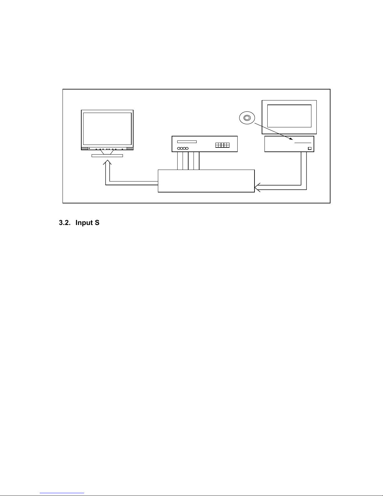
5-22
3. Inspection of PLUG & PLAY communication and OSM "MONITOR
INFORMATION" for model name/ serial number
3.1. A construction of System
This system should be connected as shown below.
PC
R G B H V
Printer Cable
Signal Generator
AUTO ADJ I/F JIG
Part No. 599910401 (120V) (For A ver.)
Part No. 599910402 (220V) (For B ver.)
PROGRAM
PART No. 599910578
Program Disk
D-Sub 15pin Signal Cable
3.2. Input Signal
Horizontal synchronization frequency : 43kHz(Negative)
Vertical synchronization frequency : 42Hz(Negative)

5-23
3.3. Operational procedures
1. Start PNP.EXE from DOS mode or DOS pronto of Windows.
2. Operation key assignment
• Determine the operation mode with the F1 ~ F9 and ESC keys.
F1 (Select Model) : Setting file changeover for respective models
F4 (Read) : EDID data for reading
F5 (Write Input 1) : It is not used in this model.
F8 (Write Input 2) : It is not used in this model.
F9 (Write ALL) : EDID data and OSM data of the writing and inspection.
ESC (EXIT) : End of program
3. Press the F1 key and enter an input of setting file for the related model. Press the Enter key.
File name Model
08EK1ABD LCD1550ME
4. Writing and inspection procedures
a. Press the F9 key (Write ALL).
b. Since the screen is changed over to the one that waits for an input of serial number, examine the
serial number of the set, enter it from the keyboard, and press the Enter key.
The message of the screen:
Model Name "LCD1550ME "
Input serial number (Enter only: Use previous number)
c. Model name and serial number writing for the OSM “MONITOR INFO.”
According to the screen commands, change over the signals, and make OSM menu setting for the
writing set.
Signal: fH 43kHz (Negative)
fV 42Hz (Negative)
When the Enter key is pressed, the model name and serial number of the OSM “MONITOR
INFORMATION” are written.
d. EDID data writing
When the Enter key is pressed, the EDID data of the D-SUB INPUT are written.
The message of the screen:
Input 1 File 1 set V 42Hz N (Hit any key)
e. Upon normal completion, a screen display is presented "OK".
f. A power-supply switch is switched off -> turned on, Display “MONITOR INFORMATION” of the OSM,
and confirm that the model name (LCD1550ME) and serial number have been correctly written.

5-24
3.4. EDID data file
The EDID data file text is shown below. When you write or inspect EDID for this monitor, the following table
can be used.
file name : L1550ME.TXT
0 1 2 3 4 5 6 7 8 9 A B C D E F
00
00 FF FF FF FF FF FF 00 38 A3 E3 65 01 01 01 01
10
*1) *2) 01 03 08 1E 17 78 EA 9D 9E 99 58 4C 93 26
20
21 4C 54 BF EE 00 01 01 01 01 01 01 01 01 01 01
30
01 01 01 01 01 01 C3 1E 00 20 41 00 20 30 10 60
40
13 00 30 E4 10 00 00 1E 00 00 00 FD 00 37 4B 1F
50
3C 08 00 0A 20 20 20 20 20 20 00 00 00 FC 00 4E
60
45 43 20 4C 43 44 31 35 35 30 4D 45 00 00 00 FF
70
00 *3) *3) *3) *3) *3) *3) *3) *3) *3) *3) *3) *3) *3) 00 *4)
Table 1 Data list (Management number : L1550ME)
Note 1: address 10h Week of manufacture = Month of manufacture × 4
Note 2: address 11h Year of manufacture - 1990
Notes 3: address 71h ~ 7Dh Serial Number (ASCII coded)
If less than 13 char, terminate with 0Ah and fill the rests with 20h.
Note 4: address 7Fh Checksum
The sum of entire 128 byte shall be equal to 00h.

6-1
TROUBLE SHOOTING
TABLE OF CONTENTS
page
1. No display of screen(Screen is black ,color of LED is amber) --------------------------------6-2
2. Nothing displays on screen(Screen is black ,color of LED is green) ------------------------6-3
3. Checking the back light unit ---------------------------------------------------------------------------6-6
4. Abnormal screen -----------------------------------------------------------------------------------------6-7
5. No OSM display ------------------------------------------------------------------------------------------6-9
6. Abnormal plug and play operation -----------------------------------------------------------------6-10
7. Checking the interface circuit of sync signal ----------------------------------------------------- 6-11
7.1 Checking the control circuit of horizontal sync pulse ---------------------------------------- 6-11
7.2 Checking the control circuit of vertical sync pulse -------------------------------------------- 6-11
8. Checking the resolution change IC movement -------------------------------------------------6-12
9. No power on ---------------------------------------------------------------------------------------------- 6-13
9.1 No power on (1) ----------------------------------------------------------------------------------------6-13
9.2 No power on (2) ----------------------------------------------------------------------------------------6-14
10. Checking the DC/DC converter circuit -----------------------------------------------------------6-15
1 1. Checking the operation of CPU ------------------------------------------------------------------- 6-16
12. Checking the audio circuit -------------------------------------------------------------------------- 6-17
13. Check the inverter board circuit -------------------------------------------------------------------6-18

6-2
1. No display of screen (Screen is black, color of LED is amber)
Does OSM display when you push
key button.
When a signal isn't being
inputted, it is indicated
with "NO VIDEOINPUT". It
is indicated with "OUT OF
RANGE" at the time of the
frequency that it can't be
distinguished.
YES
NO
Pressed "No OSM display" section.
Check if the sync signal from
Computer is output and if the
video cable is connected normally.
OK
NG
Input the sync signal of computer, or
change the cable.
Proceed "Checking the resolution
change IC movement" section.

6-3
2. Nothing displays on screen (Screen is black, color of LED is green)
Is backlight lit?
OK
NG
Does computer output
RGB video signals?
OK
NG
Check OSM menu is displayed
on screen when you push the
"NEXT" ke
y
.
OK
NG
Proceed "Abnormal screen"
section.
Refer "Checking the backlight
unit" section
Check the video cable for failure.
Check the host for output signal with
all black only.
1) Change pattern of video signal output on the host.
2) Reconnect the video cable.
3) Change the video cable.
Next page

6-4
OK
NG
Continue
Check the 3.3 V power are supplied on I310 pin 2.
OK
NG
Check if the voltage on I310
pin3 that is high level DC at 5V.
Failure point
Printed wire broke between P301 and I310
Failure point
I310 Failure
Is a dot clock being outputted under the
condition that a LCD module is connected
to P307
p
in 44?
OK
NG
Failure point
1) I306 failure
2) Printed wire broke between I306 and P307 pin 44.
Check the H-sync pulse of negative polarity
is output on P307 pin 38 at TTL level.
OK
NG
Failure point
1) I306 failure
2) Printed wire broke between I306 and P307 pin 38.
Check the V-sync of negative polarity
are output on P307 pin 40.
OK
NG
Failure point
1) I306 failure
2) Printed wire broke between I306 and P307 pin 40.
Next page

6-5
Continue
Check the data enable of positive
polarity are output on P307 pin 42.
Failure point
1) I306 failure
2) Printed wire broke between I306 and P307 pin 37.
Check the data signal output on
P306 and P307 R, G, B data pin.
OK
NG
Failure point
1) I306 failure
2) Printed wire broke between I306 and P306 data line
Failure point
1) The cable broke between P306, P307 and LCD module.
2) LCD module failure.
OK
NG

6-6
3. Checking the back light unit
Is +15V supplied to P803 pin 3, 4 to
inverter PWB?
OK
NG
Failure point
Inverter cable disconnection.
Check the INV_EN signal of the rectangle input I309 pin 5 at TTL high level
OK
NG
Is a "H" level being output in the TTL level from I302 pin 2
Or, is INV_EN signal of the rectangle being output?
NG
Failure point
Printed wire broke between
I302 pin 2 and I309 pin 5
Check the PWM signal of the input from I302 pin 1 is a BRI signal.
OK
NG
Failure point
1) Printed wire broke between
I302 pin 1 and I309 pin 3.
2
)
I309 failure.
Failure point
1) Inverter cable disconnection.
2) Inverter of LCD module failure.

6-7
4. Abnormal screen
Check the R, G, B video signal from
computer input on D-Sub R, G, B
connector.
OK
NG
Failure point
1) No R, G and B video signal output from host computer.
Check computer
2) Video signal cable disconnection.
Check the R, G, B input signals on
I306 pin 95, 91, 87 respectively that
their level is 0.7V
p-p
maximum.
OK
NG
Failure point
In the case of the Red signal. (A Green and Blue signal is
the same path, too.)
1) Printed wire broke between D-Sub(R) and I306 pin 95.
2) R346 short.
3) C348 open.
4) R345 open.
Is the pulse of the TTL level being
output to P306, P307 from the
data line of I306?
OK
NG
Failure point
1) Printed wire broke between I306 data line and P306, P307.
2) I317 failure.
Check the negative horizontal
sync pulse output to P307 pin 38
from I306
p
in 74 at TTL level.
OK
NG
Failure point
1) Printed wire broke between I306 pin 74 and P307 pin 35.
2) R350 open
3) C383 short
Next page

6-8
Continue
Check the negative vertical sync
pulse output to P307 pin 40 from
I306
p
in 73 at TTL level.
OK
NG
Failure point
1) Printed wire broke between I306 pin 73 and P307 pin 40.
2) R351 open
3) C384 short
Check the positive DE pulse
output to P307 pin 42 from I306
p
in 43 at TTL level.
OK
NG
Failure point
1) Printed wire broke between I306 pin 42 and P307 pin 42.
2) R352 open
3) C385 short
Check the SHFCLK OUTPUT to
P307 pin 44 from I306 pin 44 at
TTL level.
OK
NG
Failure point
1) Printed wire broke between I306 pin 44 and P307 pin 39.
2) FB312 open
3) FB311 open
4) C354 short
5) C355 short
Process "Checking the
resolution change IC movement"
section.

6-9
5. No OSM display
OK
NG
Check the input of pulse from I306 pin 98, 103, 99, 102, 104, 105.
Failure point
1) Printed wire broke between I306 pin 99 and I302 pin 17.
2) Printed wire broke between I306 pin 102 and I302 pin 21.
3) Printed wire broke between I306 pin 104 and I302 pin 20.
4) Printed wire broke between I306 pin 105 and I302 pin 18.
5) Printed wire broke between I306 pin 103 and I302 pin 22.
6) Printed wire broke between I306 pin 98 and I302 pin 23.
Process "Checking the resolution change IC movement" section.

6-10
6. Abnormal plug and play operation
OK
NG
Failure point
I308 failure
Confirm the input of serial clock on I308 pin 6 SCL at TTL level.
Failure point
1) The video cable may have failed or may not have connections for DDC.
2) Between I308 pin 6 and P302 pin 14 may have failed.
3) R337 open.
4) Cable failure.
OK
NG
Confirm the input of serial data on I308 pin 5 SDA at TTL level.
Failure point
1) The host machine isn't communicating in DDC2 mode.
2) The video cable may have failed or may not to have connections for DDC.
3) Between I308 pin 6 and P302 pin 13 may have failed.
4) R338 open.
5) Cable failure.
Failure point
I308 failure

6-11
7. Checking the interface circuit of sync signal
7.1 Checking the control circuit of horizontal sync pulse
7.2 Checking the control circuit of vertical sync pulse
OK
NG
Check the horizontal sync signal on I306 pin 150 TTL level.
Process "Checking the resolution change IC movement" section.
Failure point
1) Video cable may have failed.
2) Printed wire broke between P302 pin 13 and I306 pin 150.
3) FB302, R332 open.
OK
NG
Check the vertical sync signal on I306 pin 148 TTL level.
Process "Checking the resolution change IC movement" section.
Failure point
1) Video cable may have failed.
2) Printed wire broke between P302 pin 14 and I306 pin 148.
3) FB301, R328 open.

6-12
8. Checking the resolution change IC movement
Is there +3.3V supply on I306 pin 77, 79, 84, 96, 92, 88, 8, 129, 136,
139, 137, 143, 11, 21, 58, 108, 149, 12, 33, 40 and 65.
OK
NG
Proceed "Checking the DC/DC converter circuit" section.
Is 20MHz clock input to I306 pin 141 at TTL level?
OK
NG
Is 20MHz clock output from X301 at TTL level?
OK
NG
Failure point
Print wire broke between
X301 and I306 pin 141.
Failure point
X301 failure.
Is +5.0V supplied to I306 pin 100 at
High level?
OK
NG
Check the output of 5.0V "H" pulse from I301 pin 6.
OK
NG
Is 5.0V supplied to I301 pin 7?
Failure point
Print wire broke between
I301 pin 6 and I306 pin 100.
OK
NG
Failure point
1) FB318 failure
2) Power source
Failure point
I301 failure.
Failure point
I306 failure.

6-13
9. No power on
9.1 No power on (1)
Check output voltage +5V, +15V is right or not.
OK
NG
It is not power board problem.
Check power switch is turn on or not.
OK
NG
Turn switch on.
Check power cord(P801), Signal cable(P302), P802, P803 is conn ected right or not.
OK
NG
Connect it right.
Check C805 is about DC 140V-330V or not.
OK
NG
Check F801, D801, P801 and repair them.
Check C807 is over 10V or not.
OK
NG
Check R805, R803, ZD802,
Q801, I801 and repair them.
Check pin 6 of I801 have same pulse or not.
OK
NG
Check peripheral components of I801
and repair them. (e.g. Q805, Q806)
Check pin 3 of T802 have same pulse or not.
OK
NG
Check Q803, R813, R814, D806,
R812 and repair them.
Check peck voltage of R811 triangle pulse is up
to 1 volt or not.
OK
NG
Check D804, R807 and repair them.
Check D809, D810, C816, C821, T802 have
same short circuit, or the output +5V, +15V is
over load.
OK
NG
Repair them.
Check feedback circuit around I802, I803 and
the other components and repair them.

6-14
9.2 No power on (2)
Check +5V power is supplied from power source.
OK
NG
Failure point
Power source failure.
Is LED turned on in amber momentarily when a
power button is pushed ?
OK
NG
Failure point
Power source failure.
Process "Checking the operation of CPU" section.

6-15
10. Checking the DC/DC converter circuit
Check the output of 3.3V line voltage from I310 pin 2.
OK
NG
Is the output FB320 being inputted to I315 pin 3?
OK
NG
Failure point
Printed wire broke between I310 pin 3 and output of FB321.
Failure point
I310 failure
Failure point
Printed wire broke between I310 pin 2 and I306 power supply pin.

6-16
11. Checking the operation of CPU
Is there +5.0V supply on I302 pin 8.
OK
NG
Failure point
Printed wire broke between output of FB319 and I302 power supply pin.
Is 20MHz clock input to I302 pin 11 and 12 at TTL level?
OK
NG
Failure point
X301 failure.
Check the input of 5V "H" pulse from I303 pin 4 are same as I302 pin 7.
(14 msec Typ)
OK
NG
Failure point
Printed wire broke between I303 pin 4 and I302 pin 7.
I302 failure.

6-17
12. Checking the audio circuit
Is a cable with the host PC connected?
Aren't the setups of the host PC a minimum and off?
Failure point
Audio cable disconnection.
Failure point
The setup of the host PC is changed.
Is correct output waveform being inputted from JK011 pin 2, 3 of the host PC?
Failure point
Audio cable disconnection.
Is the waveform which is the same as JK011 being inputted to I001 pin 4, 9?
Failure point
1) Printed wire broke between JK011 pin 2, 3 and I001 pin 4, 9.
2) R040, R041 open.
3) R042, R043 short.
4
)
C040, C041 open.
Is output waveform being outputted in I001 pin 14, 17?
Is 15V supplied to I001 pin 15, 16?
Proceed section 9.1 "No power on (1)".
OK
OK
OK
OK
OK
OK
NG
NG
NG
NG
NG
NG
Failure point
1) Speaker cable disconnection.
2) Speaker failure.
Is mute/STD-BY low level at pin 11, pin 12.
Proceed section 11. "Checking the
operation of CPU".
OK
NG
Is Variable DC volume control at pin 6.
OK
NG
Proceed section 11. "Checking the
operation of CPU".
Failure point
I001 failure

6-18
13. Check the inverter board circuit
Check Vin pin is around 15.5V.
On/Off pin is over 2V.
Bri
g
htness pin is between 0.3V and 3.0V.
OK
NG
It is not inverter problem.
Check IC pin 3 around 5V.
OK
NG
Check Q1, Q2, Q8, D1, F1 and repair them.
Check one of these components was short
to GND.
Check CN2 and CN3 is connected right.
OK
NG
Check CCFL and repair them.
Check the IC pin 3 is PWM.
OK
NG
Check the IC pin 11 is triangle.
OK
NG
Check the Q4, Q10, R5, D5, L1
and repair them.
Check D2, C14, R11and repair them.
Check the IC pin 9 is 2.5V.
NG
Check R20 and R28 and repair them.
NG
Check the IC pin 8 feedback waveform.
Check CR1, CR2 and repair them.
NG
Repair the LM339.
OK
OK
OK
Check the buck circuit.
Next page

6-19
Check the Royer circuit.
OK
NG
Check the Q17, Q20, Q5, Q6, C13 and repair them.
Check the transformer and repair them.
Check the one of these components was short to
GND.
Check the H.V. and balance circuit.
OK
NG
Check the C3, C7, C12, C20, L3 and repair them.
Check the Feedback and protection circuit.
Check the Q19, Q7, Q11, D3, Q14 and
repair them.
Check one of these components was short
to GND.
Continue

7-1
CIRCUIT DESCRIPTION
TABLE OF CONTENTS
Page
1. Audio circuit ----------------------------------------------------------------------------------------- 7-2
1.1 Audio input ------------------------------------------------------------------------------------ 7-2
1.2 Audio output ----------------------------------------------------------------------------------- 7-2
2. Power supply ------------------------------------------------------------------------------------- 7-2
3. On-screen circuit --------------------------------------------------------------------------------- 7-3
4. Video input circuit -------------------------------------------------------------------------------- 7-3
5. Definition converter LSI peripheral circuit ------------------------------------------------- 7-3
6. System reset, LED control circuit ------------------------------------------------------------ 7-4
6.1 System reset ------------------------------------------------------------------------------------ 7-4
6.2 LED control circuit ----------------------------------------------------------------------------- 7-4
7. E
2
PROM for PnP -------------------------------------------------------------------------------- 7-4
8. E
2
PROM ----------------------------------------------------------------------------------------- 7-4
9. CPU circuit ---------------------------------------------------------------------------------------- 7-4
9.1 Detection of POWER switch status -------------------------------------------------------- 7-4
9.2 Display mode identification ------------------------------------------------------------------ 7-4
9.3 User Control ------------------------------------------------------------------------------------- 7-6
9.4 Control of definition converter MCU I306 ------------------------------------------------ 7-6
9.5 I
2
C bus control ---------------------------------------------------------------------------------- 7-7
9.6 Power ON sequence -------------------------------------------------------------------------- 7-7
9.7 Power OFF sequence ------------------------------------------------------------------------ 7-8
10. Inverter ------------------------------------------------------------------------------------------- 7-9
10.1 Circuit Diagram ------------------------------------------------------------------------------- 7-9
10.2 Inverter basic function ----------------------------------------------------------------------- 7-9

7-2
1. Audio circuit (Circuit diagrams Main PWB)
1.1 Audio input
The audio signal input received from the audio input terminal (JK011) is applied to the amplifier I001 of 4
(L-CH) and 9 (R-CH) through the low-pass filter consisting of R040, R041, R042, R043, C040 and C041.
In this amplifier, controls of Volume, and mute are conducted. The audio signal controlled at the pin 6
determines the attenuation of output of the amplifiers. Since then, the signal is output to the jack P003.
1.2 Audio output
The audio signal is output from the Audio output terminal (P003) of the jack board to the internal speaker
system.
2. Power supply (Circuit diagrams MAIN PWB)
1. Line filter consists of C801, T801, C803, C804. It eliminates high frequency interference to meet EMI’s
requirement.
2. Rec & Filter
Bridge diode D801 converts AC source into pulsed DC. This pulsed DC is smoothed and filtered by C805.
R802 is an NTC ( negative thermal coefficient ) resistor, used to reduce inrush current to be within safe
range.
3. Power transformer :
T802 converts energy for square wave from power source C805 to secondary side to generate +12V and
+5V.
4. Output :
The square wave from T802 is rectified by D809, D810, then filtered by C817, C822 to generate +12V
and +5V respectively.
4.1 A 5V power supply for LCD module, CPU and logic is generated from the power source.
4.2 I310 : 3-terminal regulator
A 3.3V power supply for I306 analog is generated from the 5V source.
4.3 I310 : 3-terminal regulator
A 3.3V power supply for I306 digital is generated from the 5V source.
Q303, Q304 ON/OFF control for LCD Module
ON/OFF control is performed for power ON/OFF and also for the power saving sequence.
5. Driver : Q803
If the electrical potential of gate is larger than source by about 10 volts, Q803 turns on.
6. FB :
Negative feedback CKT consists of photo coupler I802 and adjustable regulator I803. It can maintain
output voltages +5V and +12V at a stable level.
7. PWM :
7.1 Start : When power is turned on, R805, R803 conducts due to bias from C805. C807 is charged a 16 volt
and a starting current to pin 7 of I801. I801 starts to oscillate and outputs a pulse train through pin 6 to
drive Q803.
7.2 OPP : When Q803 turns on, C805 supplies a linearly increasing triangle current through the primary
inductance of T802 to the driver Q803, once the peak value of this current multiplied by R811 exceeds1
volt, pulse train will be shut down immediately to protect Q803, T802 from being burned out.

7-3
7.3 Regulation : If output voltage +5V goes up, the R terminal of I803 gets more bias, accordingly photo
transistor and photo diode flows more current. The voltage of pin 2 goes up too, making the pulse width
of pin 6 to become narrower. So the output voltage +5V will be pulled down to a stable value.
7.4 OVP : If +5V goes up too much, the induced voltage on pin 4 of T802 becomes large also. Suppose that
it is over 18 volts, ZD801 conducts, pin 3 of I801 is pulled up over 1 volt. The pulse train at pin 6 goes
down to zero, shutting Q803 off completely.
7.5 SCP : If output terminal is short to ground, photo transistor does not conduct, hence Q806 does not
conduct neither. The reference voltage +5V at pin 8 begins to charge on C829 and activates Q806 to
conduct either. Then oscillation of I801 is stop, shutting Q803 off completely.
LCD 1550ME Power Board Block Diagram
Line Filter
Rec.
&
Filter
Power
Transformer
Output Rec. & Filter
PWM
Driver
FB
3. On-screen circuit (Circuit diagrams Main PWB)
I306 (gmZAN1) Embeded function.
On-screen menu screen is established and the resultant data are output from I306 (Circuit diagram MAIN
PWB, gmZAN1)
4. Video input circuit (Circuit diagram MAIN PWB)
The AC-coupled video signal is used to clamp the black level at 0V.
5. Definition converter LSI peripheral circuit (Circuit diagram MAIN PWB)
I306 gmZAN1 is the definition converter LSI.
The analog R,G,B signal input entered from the video input circuit is converted into the digital data of video
signal through the incorporated A/D converter. Based on this conversion, this device performs interpolation
during pixel extension. The source voltage for this device is 3.3V and the system clock frequency is 20MHz.
The withstand voltage level for the input signal voltage is 3.3V and 5V.

7-4
6. System reset, LED control circuit (Circuit diagram MAIN PWB)
6.1 System reset
System reset is performed by detecting the rising and falling of the 5V source voltage at I301.
6.2 LED control circuit
Green / amber is lit with the control signal of the LED GREEN and LED AMBER signal pin 32, 33 from
I302 (Circuit diagram MAIN PWB).
7. E2PROM for PnP (Circuit diagram MAIN PWB)
Data transfer between I304 and host.
There are two forms of communications protocol. In both, display capabilities are retrieved by the system
software during the boot-up and configuration time.
For the PC platform, this software layer is defined in the VESA BIOS Extension / Display Data Channel,
DDC2, standard.
8. E2PROM (Circuit diagram MAIN PWB)
Data transfer between I304 (24LC32) and CPU (I302) is effected through the IIC bus SCL (pin 14) and SDA
(pin 13) of I302. The data to be transferred to each device are stored in I304.
I303 control data.
OSD related setting data.
Other control data for service menu.
9. CPU circuit (Circuit diagram MAIN PWB)
I302 (MTV312MV64) functions as the CPU.
The source voltage for the device is 5.0V and the system clock frequency is 20MHz.
9.1 Detection of POWER switch status
The CPU identifies the ON status of the two power supplies. The identification is made when the power
supply is turned off. For example, if the power supply is turned off with the POWER switch, the POWER
switch must be turned on when activating the power supply again. If the power supply is turned off by
pulling out the power cord, then this power supply can be turned on by connecting the power cord,
without pressing the POWER switch.
9.2 Display mode identification
9.2.1 Functions
(1) Display mode identification
The display mode of input signal is identified based on Table 1, and according to the frequency and
polarity (HPOL, VPOL) of horizontal or vertical sync signal, presence of the horizontal or vertical
sync signal, and the discrimination signal (HSYNC_DETECT, VSYNC_DETECT).
When the mode has been identified through the measurement of horizontal and vertical frequencies,
the total number of lines is determined with a formula of “Horizontal frequency / Vertical frequency =
Total number of lines. “Final identification can be made by examining the coincidence of the obtained
figure with the number of lines for the mode identified from the frequency.
When the detected frequency if the sync signal has changed, the total number of lines should be
counted even through it is rge identified frequency in the same mode. Then, it is necessary to
examine whether the preset value for the vertical display position of Item 4-3 has exceeded the total
number of lines. If exceeded, a maximum value should be set up, which does not exceed the vertical
display position of Item 4-3.

7-5
(2) Out of range
This out-of-range mode is assumed when the frequency of the horizontal / vertical signal is as specified
below.
Vertical frequency : Below 56.2Hz or above 75.1Hz
Horizontal frequency : Below 31.5KHz or above 60KHz
(3) Power save mode.
The power save mode is assumed when the horizontal / vertical signals are as specified below.
If there is no horizontal sync signal input.
If there is no vertical sync signal input.
If the horizontal sync signal outside the measuring range of gmZAN1.
If the vertical sync signal outside the measuring range of gmZAN1.
Table 1
Polarity
Mode No Resolution
H-freq
(KHz)
Band Width
(MHz)
H V
1. 247 VGA 720 x 350 70Hz 31.47 28.322 + -
2. 102 VGA 720 x 400 70Hz 31.47 28.322 - +
3. 103 VGA 640 x 480 60Hz 31.47 25.175 - -
4. 182 MAC 640 x 480 66Hz 35 30.24 - -
5. 173 VESA 640 x 480 72Hz 37.86 31.5 - -
6. 109 VESA 640 x 480 75Hz 37.5 31.5 - -
7. 104 VESA 800 x 600 56Hz 35.16 36 + +
8. 116 VESA 800 x 600 60Hz 37.88 40 + +
9. 110 VESA 800 x 600 75Hz 46.88 49.5 + +
10. 117 VESA 800 x 600 72Hz 48.08 50 + +
11. 108 MAC 832 x 624 75Hz 49.72 57.283 - -
12. 118 VESA 1024 x 768 60Hz 48.36 65 - -
13. 217 SUN 1024 x 768 65Hz 52.45 70.49 - -
14. 157 VESA 1024 x 768 70Hz 56.48 75 - -
15. 141 VESA 1024 x 768 75Hz 60.02 78.75 + +
Attention:
1. When resolution beyond 1024 x 768 is inputted, resolution is lowered with Down scaling to
1024 x 768, and indicated, and OSD should indicate OUT of Range.

7-6
9.3 User Control
General Key Description
Exit : Turn off OSM menu, Exit sub menu.
Control : Move the green cursor and select control items.
Adjust : Change the value of each function / Enter to submenu / Proceed auto adjust / Proceed reset
Next : Move the NEXT tag
Reset : Reset the select item (Open reset warning before reset) / Mute the speaker / headphone
sound (short cut: when no OSM menu is shown)
9.3.1 Related ports of I306
Port Pin No. I/O Signal name Function Remarks
MFB1 112 1 RESET/
Mute
RESET switch input
MUTE switch input
The set value is returned
to the initial value
MFB5 107 1 EXIT EXIT switch input Withdraw from OSD
MFB10 124 1 DOWN - switch input ( - )key
MFB4 109 1 UP + switch input ( + )key
MFB11 123 1 LEFT
3 switch input ( 3 )key
MFB3 110 1 RIGHT
4 switch input (4 )key
MFB2 111 1 NEXT NEXT switch input
9.3.2 Functions
Control is effected for the push-switches to be used when the user changes the parameters, in order to
modify the respective setting values. Whether the switch has been pressed is identified with the switch
input level that is turned “L”.
Each switch input port is pulled up at outside of MCU.
Each parameter is stored in the EEPROM, the contents of which are updated as required.
9.4 Control of definition converter MCU I306
9.4.1 Ports related to control
Pin No. I/O Signal name Function
101 I IRQ gmZan1 interrupt signal
103 O HCLK gmZan1 serial clock
99 I/O HDATA gmZan1 serial data
98 O HFS gmZan1 serial select
EXIT wCONTROL8 −ADJUST+ NEXT RESET/MUTE
 Loading...