


Part No. 78410311
Printed in Japan
NEC Multimedia Theatre
NEC Multimedia Theatre
LCD Projector
User’s Manual
NEC Technologies, Inc.
1250 N. Arlington Heights Road, Suite 500
Itasca, Illinois 60143-1248
MultiSync®MT830+
™
/1030+
™
NEC Technologies

Precautions
Please read this manual carefully before using your NEC MultiSync
MT830/1030 LCD Projector and keep the manual handy for future
reference.
Your serial number is located under the name plate label on the right side of
your MultiSync MT830/1030 . Record it here:
IMPORTANT INFORMATION
RF Interference
WARNING
The Federal Communications Commission does not allow any
modifications or changes to the unit EXCEPT those specified by
NEC Technologies in this manual. Failure to comply with this
government regulation could void your right to operate this equipment.
This equipment has been tested and found to comply with the limits
for a Class A digital de vice, pur suant to Part 15 of the FCC Rules.
These limits are designed to provide reasonable protection against
harmful interference in a commercial installation. This equipment
generates, uses and can radiate radio frequency energy and, if not
installed and used in accordance with the instructions, may cause
harmful interference to radio communications. Operation of this
equipment in a residential area is likely to cause harmful interference in which case the user will be required to correct the interference at their own expense.
DOC Compliance Notice
This Class A digital apparatus meets all requirements of the Canadian Interference-Causing Equipment Regulations.
CAUTION
LASER RADIATIONDO NOT STARE INTO BEAM
WAVE LENGTH: 645 nm (640-660 nm)
MAX. OUTPUT: 1 mW
CLASS II LASER PRODUCT
CAUTION
To turn off main power, be sure to remove the plug from power
outlet. The power outlet socket should be installed as near to the
equipment as possible, and should be easily accessible.
CAUTION
TO PREVENT SHOCK, DO NOT OPEN THE CABINET. NO USER-SERVICEABLE PARTS INSIDE.
REFER SERVICING TO QUALIFIED NEC SERVICE
PERSONNEL.
This symbol warns the user that uninsulated voltage
within the unit may be sufficient to cause electrical
shock. Therefore, it is dangerous to make any kind
of contact with any part inside of the unit.
This symbol alerts the user that important information concerning the operation and maintenance of
this unit has been provided. The information should
be read carefully to avoid problems.
WARNING
TO PREVENT FIRE OR SHOCK, DO NO T EXPOSE THIS UNIT
TO RAIN OR MOISTURE. DO NOT USE THIS UNIT’S
GROUNDED PLUG WITH AN EXTENSION CORD OR IN AN
OUTLET UNLESS ALL THREE PRONGS CAN BE FULLY INSERTED. DO NOT OPEN THE CABINET. THERE ARE HIGHVOLTA GE COMPONENTS INSIDE. ALL SERVICING MUST BE
DONE BY QUALIFIED NEC SERVICE PERSONNEL.
1
2

Important Safeguards
These safety instructions are to ensure the long life of your LCD projector and
to prevent fire and shock. Please read them carefully and heed all warnings.
Installation
1. For best results, use your LCD projector in a darkened room.
2. Place the projector on a flat, level surface in a dry area away from dust and
moisture.
3. Do not place your LCD projector in direct sunlight, near heaters or heat
radiating appliances.
4. Exposure to direct sunlight, smoke or steam can harm internal components.
5.Handle your LCD projector carefully. Dropping or jarring can damage
internal components.
6. Do not place heavy objects on top of the LCD projector .
7. If installing the LCD projector on the ceiling:
a. The ceiling must be strong enough to support the LCD projector and the
installation must be in accordance with any local building codes.
b. The LCD projector must be installed by qualified NEC service personnel.
Power Supply
1. The LCD projector is designed to operate on a power supply of 100-120 or
220-240 V 50/60 Hz AC. Ensure that your power suppl y fits this requirement
before attempting to use your LCD projector.
2. Handle the power cable carefully and avoid e xcessive bending. A damaged
cord can cause electric shock or fire.
3.If the LCD projector is not to be used for an extended period of time,
disconnect the plug from the power outlet.
Cleaning
1. Unplug the LCD projector before cleaning.
2. Clean the cabinet periodically with a damp cloth. If heavily soiled, use a mild
detergent. Nev er use strong deterg ents or solvents such as alcohol or thinner .
3. Use a blower or lens paper to clean the lens, and be careful not to scratch or
mar the lens.
4. Clean the air filter with a vacuum cleaner after every 100 hours of operation.
a. Clean the outside of the filter with a v acuum cleaner.
b. Do not use w ater or any other liquid to clean the air filter.
c. Do not operate your LCD projector without the air filter.
Lamp Replacement
• Perform lamp replacement in accordance with the instructions on page 79.
• Be sure to replace the lamp when the Status light comes on. If you continue
to use the lamp after 2000 hours of use, the lamp bulb may shatter , and pieces
of glass may be scattered in the lamp case. Do not touch them as the pieces of
glass may cause injury. If this happens, contact your NEC dealer for lamp
replacement.
• Allow a minimum of ONE minute to elapse between turning the lamp of f and
on. High voltage is applied to the lamp immediately when the power is turned
on. Therefore turning the power off and quickl y back on may shorten the life
of your lamp and result in damage to your LCD projector.
Fire and Shock Precautions
1. Ensure that there is suff icient ventilation and that vents are unobstructed to
prevent the build-up of heat inside your LCD projector. Allow at least 3
inches (10cm) of space between your LCD projector and a wall.
2. Prevent foreign objects such as paper clips and bits of paper from falling into
your LCD projector. Do not a ttempt to retrieve an y objects that might fall into
your projector . Do not insert an y metal objects such as a wire or scre wdriv er
into your LCD project. If something should fall into your projector, disconnect it immediately and have the object removed by a qualified NEC service
person.
3. Do not place any liquids on top of your LCD projector .
• Do not look into the lens while the projector is on. Serious damage to your
eyes could result.
• Do not look into the laser pointer while it is on and do not point the laser
beam at another person. Serious injury could result.
• Keep any items such as magnifying glass out of the light path of the
projector. The light being projected from the lens is extensive, therefore
any kind of abnormal objects that can redirect light coming out of the
lens, can cause unpredictable outcome such as fire or injury to the eyes.
• Do not cover the lens with the supplied lens cap or equivalent while the
projector is on. Doing so can lead to melting of the cap and possibly
burning your hands due to the heat emitted from the light output.
3
4
Ce symbole a pour but de prévenir l’utilisateur de la
présence d’une tension dangereuse, non isolée se
trouvant à l’intérieur de l’appareil. Elle est d’une
intensité suffisante pour constituer un risque
d’électrocution. Eviter le contact avec les pièces à
l’intérieur de cet appareil.
Ce symbole a pour but de prévenir l’utilisateur de la
présence d’importantes instructions concernant
l’entretien et le fonctionnement de cet appareil. Par
conséquent, elles doivent être lues attentivement
afin d’éviter des problèmes.
Importantes précautions de sécurité
Les points suivants sont des précautions de sécurité importantes destinées à
garantir une longue durée de service du projecteur à écran à cristaux liquides
(LCD) et afin d’éviter un incendie et des risques d’électrocution. S’assurer de
lire attentivement ces précautions de sécurité et respecter tous les
avertissements décrits ci-dessous.
Installation
1. Pour un fonctionnement optimal, utiliser le projecteur à écran à cristaux
liquides (LCD) dans une pièce sombre.
2. Placer le projecteur à écran à cristaux liquides (LCD) sur une surface à niveau
et dans un endroit sec exempt de poussières et d’humidité.
3. Ne pas placer le projecteur à écran à cristaux liquides (LCD) en plein soleil,
près d’appareils ménagers ou d’autres appareils de chauffage.
ATTENTION
RISQUE D’ELECTROCUTION NE PAS OUVRIR
AVERTISSEMENT
AFIN DE REDUIRE LES RISQUES D’INCENDIE OU
D’ELECTROCUTION , NE PAS EXPOSER CET APPAREIL A LA
PLUIE OU A L ’HUMIDITE. A USSI, NE PAS UTILISER LA FICHE
POLARISEE AVEC UN PROLONGATEUR OU UNE AUTRE
PRISE DE COURANT SAUF SI CES LAMES PEUVENT ETRE
INSEREES A FOND. NE PAS OUVRIR LE COFFRET, DES
COMPOSANTES HAUTE TENSION SE TROUVENT A
L’INTERIEUR. LAISSER A UN PERSONNEL QUALIFIE LE
SOIN DE REPARER CET APPAREIL.
DOC avis de conformation
DOC avis de conformation
Cet appareil numérique de la classe A respecte toutes les exigences du
Règlement sur le Matériel Brouilleur du Canada.
5
6
ATTENTION
RAYONNEMENT LASER NE PAS
REGARDER DANS LE FAISCEAU
LONGUEUR D’ONDE: 645 nm (640-660 nm)
MAX. SORTIE: 1 mW
APPREIL A LASER DE CLASSE 2
ATTENTION
Pour couper l'alimentation principale, s'assurer de retirer
la fiche de la prise de courant.
La prise de courant murale doit être installée le plus près
possible de l'équipement, et doit être facilement accessible.

4. La fumée, la vapeur et l’exposition aux rayons directs du soleil risquent de
détériorer sérieusement les composantes internes.
5. Eviter des manipulations brusques lors du déplacement du projecteur à écran
à cristaux liquides (LCD), car un choc violent pourrait endommager les
composantes internes.
6. Ne pas deposer d’objets lourds sur le dessus du projecteur à écran à cristaux
liquides (LCD).
7. Lors de l’installation du projecteur à écran à cristaux liquides (LCD) au
plafond, respecter les instructions suivantes.
a. Le plafond doit être suffisamment solide pour supporter le poids du
projecteur à écran à cristaux liquides (LCD) et il doit être installé selon
les codes de construction locaux.
b. Le projecteur à écran à cristaux liquides (LCD) doit être installé par un
personnel qualifié.
Alimentation
1. Le projecteur à écran à cristaux liquides (LCD) est conçu pour fonctionner à
100-120 ou 220-240VCA 50/60Hz. S’assurer que la tension d’alimentation
locale satisfait cette exigence avant d’utiliser le projecteur.
2.Manipuler le câble d’alimentation avec précaution et éviter de le plier
excessivement. Un cordon endommagé risque de provoquer une
électrocution ou un incendie.
3. Si le projecteur à écran à cristaux liquides (LCD) n’est pas utilisé pendant une
période prolongée, retirer la fiche de la prise secteur.
Nettoyage
1.Débrancher le projecteur à écran à cristaux liquides (LCD) de la prise
d’alimentation avant le nettoyage.
2. Nettoyer régulièrement le coffret avec un chiffon doux. S’il y a des taches
tenaces, utiliser une solution d’un détergent doux. Ne jamais utiliser de
détergents puissants ou des solvants, tel que l’alcool ou un diluant pour
nettoyer le projecteur à écran à cristaux liquides (LCD).
3. Utiliser un appareil diffuseur chauff ant ou du papier de nettoyag e de lentille
disponible dans le commerce pour nettoyer la lentille.
Ne pas frapper ou rayer la surface de la lentille, car des défauts risquent de se
produire sur la surface de la lentille.
4. Nettoyer le filtre à air toutes les 100 heures.
a. Nettoyer seulement l’extérieur avec un aspirateur.
b. Ne pas nettoyer le filtre à air avec de l’eau ou un liquide.
c. Ne pas utiliser le projecteur à écran à cristaux liquides (LCD) sans
le filtre à air.
Remplacement de la lampe
• Ef fectuer le remplacement de la lampe suivant les instructions de la page
83.
• Assurez-vous de bien remplacer la lampe lorsque le voyant d’usure
s’allume. Si vous continuez d’utiliser la lampe après 2000 heures
d’utilisation, l’ampoule peut se briser et des brisures de verre peuvent être
éparpillées dans le compartiment de la lampe. Ne les touchez pas car elles
peuvent vous blesser. Dans ce cas, contactez votre revendeur NEC afin de
procéder au remplacement de la lampe.
• Attendez minimum UNE minute après avoir éteint la lampe avant de la
rallumer. Une haute tension est immédia tement appliquée à la lampe quand
celle-ci est mise sous tension. Par conséquent, éteindre, puis tout de suite
rallumer peut abréger la vie de votre lampe et endommager votr e projecteur
LCD.
Précautions pour éviter un incendie ou
une électrocution
1. Une ventilation appropriée doit être assurée afin d’éviter une accumulation de
chaleur à l’intérieur du projecteur à écran à cristaux liquides (LCD). S’assurer
que les trous de ventilation ne sont pas obstrués. Laisser un espace d’au moins
10 cm (quatre pouces) entre le projecteur à écran à cristaux liquides (LCD) et
les murs.
2. Eviter que des objets étrangers, des agrafes, des clous et du papier, par
exemple, pénètrent à l’intérieur du projecteur à écran à cristaux liquides
(LCD). Ne pas essayer de récupérer ces objets soi-même ou ne pas insérer des
objets métalliques, des fils et des tourne-vis, par exemple à l’intérieur du
projecteur à écran à cristaux liquides (LCD). Si un objet tombe à l’intérieur
du projecteur à écran à cristaux liquides (LCD), le débrancher
immédiatement et contacter un dépanneur qualifié pour retirer l’objet.
3. Ne pas placer des liquides sur le dessus du projecteur à écran à cristaux
liquides (LCD).
• Ne regardez pas à l’intérieur de l’objectif lorsque le projecteur est en
marche. Vous risquez de vous blesser gravement aux yeux.
• Ne regardez pas à l’intérieur de la flèche laser lorsque celle-ci est en
marche et ne dirigez pas le rayon laser sur une autre personne. Vous
risquez de provoquer ue blessure grave.
• Conserver tout objet du type loupe hors du faisceau de lumière du
projecteur. La lumière projetée par la lentille etant très importante, tout
objet anormal pouvant détourner la lumière qui sort de la lentille peut
donc avoir des conséquences imprévisibles, telles qu'un feu ou une
blessure au yeux.
• Ne pas couvrir la lentille av ec le couvercle de lentille four ni pendant que le
projecteur est allumé. Le couvercle pourrait fondre et vous vous
bruleriez les mains à cause de la chaleur émise par la source de lumière.
7
8

NEC MultiSync® LCD Projector
Products
NEC T echnolo gies, Inc. (hereafter NECTECH) warrants this product to be free
from defects in material and workmanship under the following terms.
HOW LONG IS THE WARRANTY?
Parts and labor are warranted for (2) two years from the date of the first customer
purchase. The lamp is warranted for 2000 hours of operating time or six months,
whichever comes first.
WHO IS PROTECTED?
This warranty may be enforced only by the first purchaser.
WHAT IS COVERED AND WHAT IS NOT COVERED
Except as specified below, this warranty covers all defects in material or
workmanship in this product. The following are not covered by the warranty:
1. Any product which is not distributed in the U.S.A. or Canada by NECTECH
or which is not purchased in the U.S.A. or Canada from an authorized
NECTECH dealer. For a listing of authorized dealers please contact
NECTECH at 800-836-0655.
2. Any product on which the serial number has been defaced, modified or
removed . NECTECH’S LIABILITY FOR ANY DEFECTIVE PRODUCT
IS LIMITED TO THE REPAIR OR REPLA CEMENT OF THE PR ODUCT
AT OUR OPTION. REPLACEMENT PRODUCTS MAY BE NEW OR
‘LIKE NEW’.
3. NECTECH SHALL NOT BE LIABLE FOR : Damage, deterioration or
malfunction resulting from:
a. Accident, misuse, abuse, neglect, fire, water, lightning or other acts of
nature, unauthorized product modification, or failure to follow instruc-
tions supplied with the product.
b. Repair or attempted repair by anyone not authorized by NECTECH.
c. Any shipment of the product (claims must be presented to the carrier).
d. Removal or installation of the product.
e. Any other cause which does not relate to a product defect.
4. Cartons, carrying cases, batteries, external cabinets, magnetic tapes, or any
accessories used in connection with the product.
WHAT NEC WILL COVER
W e will pay labor and material expenses for co vered items. But we will not pay
for the following:
1. Removal or installa tion char ges.
2. Costs of initial technical adjustments (set-up), including adjustment of user
controls. These costs are the responsibility of the NECTECH dealer from
whom the product was purchased.
3. Payment of shipping charges.
HOW YOU CAN GET WARRANTY SERVICE
1.To obtain service on your product, consult the dealer from whom you
purchased the product.
2. Whenever warranty service is required, the original dated invoice (or a copy)
must be presented as proof of warranty coverage. Please be prepared to
describe or demonstrate the problem to your dealer.
3.For the name of the nearest NECTECH authorized service center, call
NECTECH at 800-836-0655.
LIMITATION OF IMPLIED WARRANTIES
ALL IMPLIED WARRANTIES, INCLUDING WARRANTIES OF MERCHANTABILITY AND FITNESS FOR A PARTICULAR PURPOSE, ARE
LIMITED IN DURATION TO THE LENGTH OF THIS WARRANTY.
EXCLUSION OF DAMAGES
NECTECH’S LIABILITY FOR ANY DEFECTIVE PRODUCT IS LIMITED
TO THE REPAIR OR REPLACEMENT OF THE PRODUCT AT OUR
OPTION. NECTECH SHALL NOT BE LIABLE FOR:
1. DAMAGE TO OTHER PROPERTY CAUSED BY ANY DEFECTS IN
THIS PRODUCT , D AMAGES B ASED UPON INCONVENIENCE, LOSS
OF USE OF THE PRODUCT, LOSS OF TIME, COMMERCIAL LOSS;
OR
2. ANY OTHER DAMAGES, WHETHER INCIDENTAL, CONSEQUENTIAL OR OTHERWISE. SOME STATES DO NOT ALLOW LIMITATIONS ON HOW LONG AN IMPLIED WARRANTY LASTS AND/OR
DO NOT ALLOW THE EXCLUSION OR LIMITATION OF INCIDENTAL OR CONSEQUENTIAL DAMAGES, SO THE ABOVE LIMITATIONS AND EXCLUSIONS MAY NOT APPLY TO YOU.
HOW STATE LAW RELATES TO THE WARRANTY
This warranty gives you specific legal rights, and you may also have other rights
which vary from state to state.
FOR MORE INFORMATION, TELEPHONE 800-366-5213
NEC TECHNOLOGIES, INC.
1250 N. Arlington Heights Road, Suite 500
Itasca, Illinois 60143-1248
NOTE: All products returned to NECTECH for service MUST have
prior approval. To get approval, call NEC Technologies at
800-836-0655.
LIMITED WARRANTY 9
10

1. Introduction
Introduction To The MultiSync MT830/1030 LCD Projector ......................................... 13
How Do You Get Started? ............................................................................................... 15
What ’s In The B o x ? ........................................................................................................ 15
Getting To Know Your MultiSync MT830/1030 LCD Projector ..................................... 17
Front / Rear Features................................................................................................ 17
Side Features ........................................................................................................... 17
Top Features ............................................................................................................ 19
Terminal Panel Features........................................................................................... 21
Remote Control Features ......................................................................................... 25
2. Installation
Setting Up Your MultiSync MT830/1030 LCD Projector ............................................... 31
Selecting A Location ................................................................................................ 32
Using A Tabletop Or Cart......................................................................................... 33
Ceiling Installation ................................................................................................... 39
Reflecting The Image............................................................................................... 43
Rear Screen Projection............................................................................................. 44
Wiring Diagram .............................................................................................................. 45
Connecting Your PC Or Macintosh Computer ................................................................ 47
Connecting Your Document Camera ............................................................................... 53
Connecting Your VCR Or Laser Disc Player .................................................................. 53
Connecting An External Monitor .................................................................................... 54
Connecting Your Computer To The Mouse Output Port.................................................. 55
TABLE OF CONTENTS
3. Operation
General Controls ............................................................................................................. 57
Using The Menus............................................................................................................ 59
Menu Descriptions & Functions ..................................................................................... 61
Source Menu (Source Icons) .................................................................................... 61
Image Adjust Menu(Sound And Picture Control Icons) ........................................... 63
Power Menu(Projector Control Icons) .................................................................... 67
Settings Menu(Maintenance Icons) .......................................................................... 69
Using the Viewer function........................................................................................ 71
4. Maintenance
Replacing The Lamp ....................................................................................................... 79
Cleaning Or Replacing The F ilter ................................................................................... 81
Remote Control Battery Installation................................................................................ 82
5. Troubleshooting
Status Light Messages..................................................................................................... 87
Common Problems & Solutions...................................................................................... 89
6. Specifications
Optical ............................................................................................................................ 91
Electrical ......................................................................................................................... 92
Mechanical ..................................................................................................................... 92
D-Sub Pin Assignments .................................................................................................. 95
Timing Chart................................................................................................................... 97
PC Control Command Reference .................................................................................... 99
Cable Connection.......................................................................................................... 103
11
12

This section introduces you to your new MultiSync MT830 (SVGA)/
MT1030 (XGA) LCD Projector, provides a list of materials that comes
with your projector and describes the features and controls.
Congratulations On Your Purchase Of The MultiSync
MT830/1030 LCD Projector
The MultiSync MT830/1030 is one of the very best LCD projectors
available today. The multiple LCD panels enable you to project
precise images up to 300 inches across (measured diagonally) from
your PC or Macintosh computer (desktop or notebook), VCR, DVD
player, document camera, or even a laser disc player.
You can use the projector on a tabletop or cart, you can permanently
mount it on a ceiling*1, or you can use MultiSync MT830/1030 LCD
Projector to project images from behind the screen. The remote
control can be used wirelessly or with a cable, and you can even use
the remote control with the built-in remote mouse receiver to operate
the mouse on your PC or Mac. But best of all, the MultiSync MT830/
1030 is an NEC LCD projector. Tha t means you can depend on years
of reliable performance and crystal-clear presentations!
INTRODUCTION1
Features you’ll enjoy:
• Simple set up and operation.
• Hot air blown from the vents does not bother the audience dur ing
your presentation since the vents are located on the front.
•
A high-performance 150 watt short arc high pressure lamp that is
guaranteed for 2000 hours of service or six months, whichever comes
first.
• A wireless remote control that operates the projector from any
angle.
• A laser pointer that' s built into the remote control.
• The power zoom control enables you to adjust the image to be
between 20 and 300 inches (measured diagonally).
• Keystone correction allows you to correct trapezoidal distortion
so that the image is square.
• White balance control allows you to adjust the brightness and
contrast for each RGB color.
• You can choose between video modes depending on y our source:
"normal" for a typical picture, "natural" for true color reproduction, and "camera" for use with a document camera or low APL
picture.
• The optional MT View er kit allows you to start your presentation
even when a PC is not available at the site.
• The "image capture" enables you to use the entire picture as a
background image or to create slides (optional MT Viewer required).
• An image can be projected from in front or behind a screen, and
the projector can even be installed on the ceiling.
• NEC Tec hnologies' exclusive AccuBlend™ intelligent pixel
blending technology - an extremely accurate image compression
technology - offers a crisp image with SXGA (128021024)
resolution*3. You can select any point on the screen with the
pointer and enlarge the selected area.
•
Supports most IBM VGA, SVGA, XGA
*2, SXGA(with
AccuBlend)*3, Macintosh, or any other RGB signals within a horizontal frequency range of 15.754 to 85 kHz and a v ertical frequenc y
range of 50 to 85 Hz. This includes NTSC, PAL, SECAM and
NTSC4.43 standard video signals.
Note: Composite video standards are as follows:
NTSC: U.S. TV standard for video in U.S. and Canada.
PAL: TV standard used in western Europe.
SECAM: TV standard used in France and Eastern Europe.
NTSC4.43: TV standard used in Middle East countries.
• The remote control can be used with or without a cable, and you
can even use the remote to operate your PC or Macintosh mouse
wirelessly from across the room with the built-in remote mouse
receiver.
• You can control your MultiSync MT830/1030 LCD Projector
with a PC.
• The contemporary cabinet design is compact, easy to carry, and
complements any office, board room or auditorium.
• Eight kinds of pointers are available for your presentation.
*1Installing the MultiSync MT830/1030 LCD Projector on the
ceiling must be done by authorized NEC technicians.Consult
your NEC dealer for more information.
*2An XGA image (10242768) is converted into a 8002600 crisp
image with NEC technology's AccuBlend.
*3An SXGA image (128021024) is converted into a 10242768
crisp image with NEC technology's AccuBlend.
INTRODUCTION
13
14
How Do You Get Started?
The fastest way to get started is to take your time and do everything
right the first time. Take a few minutes now to watch the introductory
video and revie w the manual. This may sa ve you hours later on. At the
beginning of each section of the manual you'll find an overview. If the
section doesn't apply , y ou can skip it.
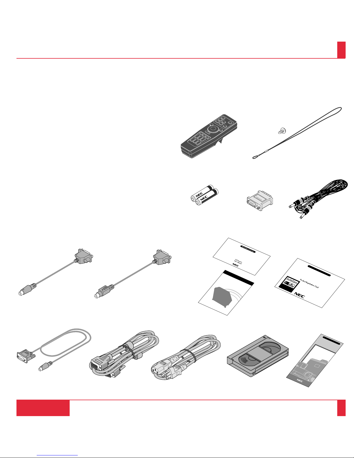
What’s In The Box?
Make sure your box contains everything listed. If any pieces are missing,
contact your dealer. Please save the original box and packing materials if
you ever need to ship your MultiSync MT830/1030 LCD Projector.
• NEC MultiSync MT830/1030 LCD Projector
• Remote Control With Built-In Laser Pointer And Cables
• Mouse Ada pter for IBM PS/2 and Mac
• Serial Cable
• Signal Cable (15-Pin Mini D-Sub To 15-Pin Mini D-Sub Connector)
• Pin Adapter for Macintosh
• Power Cable
• T wo AA Batteries
• Quick Connect Guide
• Introductory Video
• User's Manual
• Accessory Catalog
• Registration Card
• String and rivet
INTRODUCTION
15
16
Batteries (AA22) Pin adapter for
Macintosh
Remote cable
Remote control
Mouse adapter (For Macintosh)
MultiSync
MT
1020
and MT
820
Accessories
Accessory catalog
MultiSync MT
830/1030
User’s manual
Signal cable
(15-Pin Mini D-Sub To 15-Pin Mini D-Sub connector)
Power cable
MultiSync MT
Series
LCD Projector
Registration cardMouse adapter (For IBM PS/2)
Introductory videoSerial cable
String and rivet
Quick Connect Gide
Quick connect guide

PC CONTROLMOUSE OUTPUT
REMOTE
CONTROL
INPUT
AUDIORGB INPUT 2
AUDIORGB INPUT 1
AUDIORGB MONITOR OUTPUT
RL/MONO
INPUT AUDIOS–VIDEO
RL/MONO
INPUT AUDIOVIDEO
AC IN
Built-In Speaker
(2W)
Getting To Know Your MultiSync
MT830/1030 LCD Projector
AC Input
Plug the female end of the supplied
power cable here, and the male end
into a properly grounded outlet.
Remote Sensor
Filter Cover
Rear Feet
Slot for Kensington
MicroSaver Security System
Main Power Switch
Right Side Features
Lamp Cover
Lamp Cover Set Screw
Left Side Features
Remote Sensor
Remote Sensor
Front Features
One-Touch
Tilt button
Lens And Lens Cap Remote Sensor
Front Vent
Front Feet
Rear Features
Carrying Handle
INTRODUCTION
17
18
One-Touch
Tilt button
Built-In Speaker
(2W)
Slot Cover for the Optional
MT Viewer Board.
Latch
Carrying Handle
Terminal Panel
Connector Cap

Top Features
1 Power Button
Use this button to turn the po wer on and off w hen the Main Power Switch is on and
the LCD projector is in standby .
2 Menu Button
Displays the on- screen menu.
3 Select (▲▼
§ ©
) / (+)(–) Buttons
Select: After you press the “Menu” button, use the ▲ or ▼ button to select the
menu icon of the item you wish to adjust.
(+)(–): Use these buttons while you' re in the Image Adjust mode to change the
level of a selected menu item. These buttons are also used to set an item
in the Power or Settings menus.
4 Enter Button
Executes your menu selection.
5 (+) (–) Zoom Buttons
Press the (+) button to make the image larg er; press (–) to make the ima ge smaller .
6 (+) (–) Focus Buttons
Press the (+) or (–) buttons to focus an image.
7 Power Indicator
When this indicator is green, the LCD projector is on; when the indicator is amber, it
is standing by.
8 Status Indicator
When this is lit red continually, it's warning you that the projection lamp has exceed
2000 hours of service. After this light appears, it is advisable to replace the projection
lamp as soon as possible.(See pages 79 and 80)
In addition the message "LAMP USAGE XX HOURS" appears continually when
the on-screen menu is not displayed.
If this light blinks red rapidly, it indicates that either the lamp cover or filter cover is
not attached properly. See the Status Light Messages on pages 87 and 88 for more
details.
INTRODUCTION
19
20
MENU
SELECT
ENTER
ON/OFF
ZOOM FOCUS
STATUS
POWER
–
+–+
–
+
2
3
4
6
5
1
8
7
(▲▼
§ ©
)

Terminal Panel Features
This panel is located on the left side and is where you connect your cables.
1 S-Video Input
Here is where you connect the S-Video input from an external
source like a VCR.
Left Channel/Mono Audio Input J ack
This is your left channel audio input for stereo sound coming from
S-Video equipment or audio system. This also serves as your
monaural audio input.
Right Channel A udio Input Jac k
This is your right channel audio input for stereo sound.
NOTE: S-Video provides more vivid color and higher resolution
than the traditional composite video format.
2 Video Input
Connect a VCR, DVD pla yer, laser disc player, or document camera
here to project video.
Left Channel/Mono Audio Input J ack
This is your left channel audio input for stereo sound coming from
video equipment or audio system. This also serves as y our monaural
audio input.
Right Channel Audio Input J ack
This is your right channel audio input for stereo sound.
3 RGB Monitor Output Connector (Mini D-Sub 15 pin)
You can use this connector to loop your computer image to an
external monitor from either the RGB 1 or RGB 2 input source.
Audio Output Mini Jack
Connect additional external speakers here to listen to audio coming
from your computer, V ideo or S-Video input.
4 RGB Input 1 Connector (Mini D-Sub 15 pin)
Connect your PC or other RGB equipment such as IBM or compatible computers. Use the signal cable that's supplied to connect to a
PC. Or connect a Macintosh or compatible computer here using the
signal cable and the pin adapter that is supplied.
RGB 1 Audio Input Mini Jack
This is where you connect RGB audio output from a computer or
another RGB source.
INTRODUCTION
21
22
PC CONTROL MOUSE OUTPUT
REMOTE
CONTROL
INPUT
AUDIORGB INPUT 2
AUDIORGB INPUT 1
AUDIORGB MONITOR OUTPUT
RL/MONO
INPUT AUDIOS–VIDEO
RL/MONO
INPUT AUDIOVIDEO
13
24

INTRODUCTION
23
24
5 RGB Input 2 Connector (Mini D-Sub 15 pin)
Connect a Macintosh or compatible computer here using the signal
cable and the monitor adapter that is supplied. Or connect your PC
or other RGB equipment such as IBM or compatible computers.
Use the signal cable that is supplied to connect to a PC.
RGB 2 Audio Input Mini Jack
This is where you connect a second RGB audio output from a
computer or another RGB source.
6 PC Control Port
Use this port to connect your PC to control the MultiSync MT830/
1030 Projector. This enables you to use your PC and serial communication protocol to control the projector. If you are writing your
own program, command references ar e on pages 99 to 102.
A cap is put on the port at the factory. Remove the cap when using
the port.
7 Mouse Output Port
Use this port to operate your computer’ s mouse functions fr om the
NEC MultiSync MT830/1030 remote control. When your computer is connected here, the remote sensors on the LCD projector
cabinet will recei ve your mouse commands.
8 Remote Control Jac k
Connect your remote control cable here for wired operation.
9 Built-in Security Slot ( )
This security slot supports the MicroSaver® Security System.
MicroSaver® is a registered trademark of Kensington Microware
Inc. The logo is trademarked and owned by Kensington
Micro ware Inc.
PC CONTROL MOUSE OUTPUT
REMOTE
CONTROL
INPUT
AUDIORGB INPUT 2
AUDIORGB INPUT 1
AUDIORGB MONITOR OUTPUT
RL/MONO
INPUT AUDIOS–VIDEO
RL/MONO
INPUT AUDIOVIDEO
678
5
AC IN
9

Remote Control Features
You can use your remote control with the cable or wireless to operate
your MultiSync MT830/1030 LCD Projector. With the mouse output
port connected to your computer, you can also use the projector's
remote control to operate your computer's mouse wireless. (See pages
55 and 56 to connect your computer to the mouse output port.)
If you want to use your remote control with the cable, connect one end
of the cable to the jack on the remote control and the other end to the
Terminal Panel.
NOTE: If you ar e using a Macintosh computer, you can click either the
right or left button to activate the mouse.
1 Left Click Button
Use this button to enter your menu selection. It works the same as
the "Enter" button on the cabinet.
2 Laser Pointer
Beams a laser light when "Laser" button is pressed.
3 Infrared T ransmitter
Direct the remote control toward the remote sensor on the projector
cabinet.
INTRODUCTION
25
26
OFF ON
PC CARD
VIDEO
RGB 1
MENU
R-CLICK/CANCEL
LASER
SLIDE
VOLUME
S-VIDEO
POINTER
MAGNIFY
PIC-MUTE FREEZE
RGB 2
+
–
+
–
+
–
+
–
FOCUS
KEYSTONE
ZOOM
+
–
+
–
+
–
POWER
4 LED
Flashes when any button is pressed.
5 Power On And Off
If your main power switch is turned on, you can use this button to
turn your MultiSync MT830/1030 LCD Projector on and off.
6 Video Button
Press to select an NTSC, PAL, SECAM or NTSC4.43 compatible
video source from a VCR, DVD player, laser disc player or document camera.
7 S-Video Button
Press to select an S-Video source fr om a VCR.
8 RGB 1 Button
Press to select a video source from a computer connected to your
RGB 1 port.
9 RGB 2 Button
Press to select a video source from a computer connected to your
RGB 2 port.
10 PC Car d Button
Press to display a slide from the flash memory card inserted in the
PC card slot of your LCD projector. (You must first install the
optional MT Viewer board into your LCD projector.)
1
3
2
4
5
10
6
7
8
9

INTRODUCTION
27
28
OFF ON
PC CARD
VIDEO
RGB 1
MENU
R-CLICK/CANCEL
LASER
SLIDE
VOLUME
S-VIDEO
POINTER
MAGNIFY
PIC-MUTE FREEZE
RGB 2
+
–
+
–
+
–
+
–
FOCUS
KEYSTONE
ZOOM
+
–
+
–
+
–
POWER
15 Freeze Button
This button will freeze a picture. Press again to resume motion.
16 Picture Mute Button
This button turns off the image for a short period of time. Press
again to restore the image.
17 Pointer Button
Use this button to move your Pointer icon to the area you want on
the screen, then press the Magnify button on the remote control to
enlarge the selected area on the screen.
When you're finished, the "Pointer" button will remain lit for 10
seconds.
NOTE:
* Eight kinds of Pointers (icons) are available. You can select one
from the Settings Menu. The magnifying glass icon is selected a t
the factory. See page 70 for more details.
* With the Pointer button pressed, the Mouse Pad is used to move
the picture.
18 Volume Button
Press (+) to increase the volume and (-) to decrease it.
14
15
16
17
18
11 Laser Button
Press and hold this button to activa te the laser pointer. W hen lit, you
can use the laser to draw your audience's attention to a red dot that
you can place on any object within 30 feet (10 m).
12 Menu Button
Use this button to call up the On-Screen Menu so you can adjust and
set the image. After you press this button, it will light up. During
this time you can use the mouse pad and right/left click buttons to
make menu selections.
If no buttons are pressed within 10 seconds while it illuminates, the
light goes out. To return to the main menu from a submenu, press
this button again.
13 Mouse Pad(▲▼
§
©
/+ -)
Works as a mouse for your projected computer image. This pad is
also used to adjust position.
This pad selects the submenu you want to adjust. (See page 59.)
After you make your on-screen menu selection, use this pad to
adjust the level up or down. (See page 59.)
14 Right Click/Cancel Button
Press this button to exit "Menus" or "Pointer."
1112
13

INTRODUCTION 30
29
Remote Control Precautions
• Do not look into the laser pointer while it is on.
• Do not point the laser beam at a person.
• When the cable is connected to the remote control, it will not work
in the wireless mode.
• Handle the remote control carefully.
• If the remote control gets wet, wipe it dry immediately.
• Avoid excessiv e hea t and humidity .
•
If you will not be using the remote control for a long time, remov e the
batteries.
• Do not mix new and old or different types of batteries.
19 Slide Button
Press (+) to advance the next file or slide and (-) to return to the
previous file or slide. (the optional MT Viewer board required)
20 Magnify Button
Use the (+) or (-) button to adjust the image size up to 400%.
When the Pointer is displayed, the magnified image is displayed at
the center of the Pointer.
When the Pointer is not displayed, the magnified image is displayed
at the center of the screen.
21 Keystone Button
Press the (+) or (-) button to correct the keystone (trapezoidal)
distortion, and make the image square.
22 Focus Button
Press the (+) or (-) button to adjust the focus.
23 Zoom Button
Press the (+) button to zoom in and the (-) button to zoom out.
24 Remote Jack
Connect your remote control cable here for wired operation.
NOTE: You cannot use Men u and Pointer at the same time.
OFF ON
PC CARD
VIDEO
RGB 1
MENU
R-CLICK/CANCEL
LASER
SLIDE
VOLUME
S-VIDEO
POINTER
MAGNIFY
PIC-MUTE FREEZE
RGB 2
+
–
+
–
+
–
+
–
FOCUS
KEYSTONE
ZOOM
+
–
+
–
+
–
POWER
19
20
21
22
23
24

This section describes how to set up your MultiSync MT830/1030 LCD
projector and how to connect video and audio sources.
Setting Up Your MultiSync MT830/1030 LCD
Projector
Your MultiSync MT830/1030 LCD Projector is simple to set up and use. But
before you get started, you must first:
1. Determine the image size
2. Set up a screen or select a non-glossy white wall onto which you can project
your image.
Carrying The LCD Projector Always carry your LCD projector by the
handle. Ensure that the power cord and any other cables connecting to video
sources are disconnected before moving the projector. When moving the
projector or when it is not in use, cover the lens with the lens cap.
INSTALLATION2
Selecting A Location The further your LCD projector is from the screen or
wall, the larger the image. The minimum size the image can be is approximately 20" (0.5 m) measured diagonally when the projector is roughly 3 feet
(1.0 m) from the wall or screen. The largest the image can be is 300" (7.6 m)
when the projector is about 40.03 feet (12.2 m) from the wall or screen.
Throw Distance
Diagonal Screen Size (inch)
Projection Distance and Image Size
INSTALLATION
31
32
Width
Height
Screen size
(diagonal)
Projection distance
Rivet
String
Lens cap
Attaching the lens cap to the lens hood
with the supplied string and rivet.
350
300
250
200
150
100
50
0
0.0 6.56 13.12 19.69 26.25 32.81 40.03 ft.
(2.0) (4.0) (6.0) (8.0) (10.0) (12.2) (m)
300”
235”
WIDE
TELE
27”
20”

Using A Tabletop Or Cart
1. Place your LCD projector on a flat level surface at the optimal
distance from the screen or wall so you realize the size image you
want. (Avoid having bright room lighting or sun light directly on the
screen or wall where you'll be projecting the image.)
2. Connect the power cable, remove the lens cap and turn the projector
on. (If no input signal is available, the projector will display a
background image.)
3. Ensure that the projector is square to the screen.
4. Move the projector left or right to center the image horizontally on
the screen. (A)
5. T o center the image v ertically (B), lift the front edge of the projector
and press the buttons on the front of the projector, just above the
feet, to release the one-touch tilt feet. (There is approximately 10.5˚
of up and down adjustment for the fr ont of the projector. )
INSTALLATION
33
34
6. If a trapezoidal distortion appears on the screen, use the KEYSTONE button on the remote control or select Keystone from the
menu to correct the distortion.
If necessary, adjust the front or rear feet so that the lens surface is
parallel to the screen. If you use the projector with the screen tilted,
the picture will be distorted. Each of the rear feet height can be
changed up to 0.6" (4 mm).
7. Increase or reduce the size of the projected image by pressing the
"Zoom" (+) or (–) buttons on the remote control or top of the
cabinet.
(A) Top view
(B) Side view
screen
screen

35
36
Distance Chart
A
C
D
E
Formulas(mm)
"H=Horizontal Screen Width
M=1.25H/33.02(Projection magnification)
A=C/cosα
C (WIDE)=53.22M-85.609
C (TELE)=C(WIDE)21.3055
D ={(3H/8)-(92.2+8M)}
=1.906M-92.2
E=92.2+8M
Formulas(inch)
"H=Horizontal Screen Width
M=1.25H/1.3(Projection magnification)
A=C/cosα
C (WIDE)=2.094452M-3.37
C (TELE)=C(WIDE)21.3055
D ={(3H/8)-(92.2+8M)}/25.4
=(1.906M-92.2)/25.4
E=(92.2+8M)/25.4
A : Distance between the lens and the screen center
C : Horizontal throw distance between the screen surface and the lens
D : Vertical distance between the projector foot and the bottom of image
E : Vertical distance between the projector foot and the screen center
INSTALLATION
α

37
38
Standard Zoom Lens (Wide)
α
β (sin= α)
γ (cos= α)
Screen Size
H–Width
4 : 3 Diagonal
A
C
D
E
Degree
inch
inch
mm
inch
mm
inch
mm
inch
mm
inch
9.02
0.15671
0.98764
32
40
1572
61.9
1552
61.1
-34
-1.32
339
13.3
8.86
0.15395
0.98808
48
60
2400
94.5
2371
93.4
-4
-0.16
462
18.2
8.81
0.15318
0.98820
56
70
2814
110.8
2781
109.5
10
0.41
523
20.6
8.78
0.15260
0.98829
64
80
3228
127.1
3190
125.6
25
0.99
585
23.0
8.75
0.15216
0.98836
72
90
3642
143.4
3600
141.7
40
1.57
646
25.4
8.73
0.15181
0.98841
80
100
4056
159.7
4009
157.8
55
2.15
708
27.9
8.70
0.15128
0.98849
96
120
4884
192.3
4828
190.1
84
3.30
831
32.7
8.67
0.15076
0.98857
120
150
6127
241.2
6057
238.4
128
5.03
1016
40.0
8.65
0.15041
0.98862
144
180
7369
290.1
7285
286.8
172
6.77
1201
47.3
8.64
0.15024
0.98865
160
200
8197
322.7
8104
319.1
201
7.92
1324
52.1
8.63
0.14998
0.98869
192
240
9853
387.9
9742
383.5
260
10.23
1570
61.8
8.62
0.14984
0.98871
216
270
11096
436.8
10970
431.9
304
11.96
1755
69.1
Standard Zoom Lens (Tele)
INSTALLATION
8.61
0.14972
0.98873
240
300
12338
485.7
12199
480.3
348
13.70
1939
76.4
α
β (sin= α)
γ (cos= α)
Screen Size
H–Width
4 : 3 Diagonal
A
C
D
E
Degree
inch
inch
mm
inch
mm
inch
mm
inch
mm
inch
6.93
0.12065
0.99269
32
40
2041
80.4
2027
79.8
-34
-1.32
339
13.3
6.81
0.11850
0.99295
48
60
3118
122.7
3096
121.9
-4
-0.16
462
18.2
6.77
0.11790
0.99302
56
70
3656
143.9
3630
142.9
10
0.41
523
20.6
6.75
0.11746
0.99308
64
80
4194
165.1
4165
164.0
25
0.99
585
23.0
6.73
0.11711
0.99312
72
90
4732
186.3
4699
185.0
40
1.57
646
25.4
6.71
0.11684
0.99315
80
100
5270
207.5
5234
206.1
55
2.15
708
27.9
6.69
0.11643
0.99320
96
120
6346
249.9
6303
248.2
84
3.30
831
32.7
6.66
0.11603
0.99325
120
150
7961
313.4
7907
311.3
128
5.03
1016
40.0
6.65
0.11576
0.99328
144
180
9575
377.0
9511
374.4
172
6.77
1201
47.3
6.64
0.11562
0.99329
160
200
10651
419.3
10580
416.5
201
7.92
1324
52.1
6.63
0.11542
0.99332
192
240
12804
504.1
12718
500.7
260
10.23
1570
61.8
6.62
0.11531
0.99333
216
270
14418
567.6
14322
563.8
304
11.96
1755
69.1
6.62
0.11522
0.99334
240
300
16032
631.2
15925
627.0
348
13.70
1939
76.4

INSTALLATION 40
WARNING
•
Only use your LCD projector on a solid, level surface. If the projector falls to the ground, you can be injured and the projector
sev erel y dama ged.
• Do not use the LCD projector where temperatures vary greatly . The projector m ust be used at temperatures between 32˚F
(0˚C) and 104˚F (40˚C).
•
Do not expose the LCD projector to moisture, dust, or smoke. This will har m the scr een image.
•
Ensure that you have adequate v entilation around your LCD projector so heat can dissipate. Do not cov er the vents on the side
or the front of the projector.
Ceiling Installation
Installing your MultiSync MT830/1030 LCD Projector on the ceiling must be done by a qualified technician. Contact your
NEC dealer for more information.
Do not attempt to install the projector yourself.
NOTE : Distances may vary ±5%.
39
Formulas(mm)
"H=Horizontal Screen Width
M=1.25H/33.02(Projection magnification)
A=C/cosα
B=85.2+8M
C(WIDE)=53.22M-85.609
C(TELE)=C(WIDE)21.3055
F={(3H/8)-(85.2+8M)}
=1.906M-85.2
Formulas(inch)
"H=Horizontal Screen Width
M=1.25H/1.3(Projection magnification)
A=C/cosα
B=(85.2+8M)/25.4
C(WIDE)=2.09452M-3.37
C(TELE)=C(WIDE)21.3055
F={(3H/8)-(85.2+8M)}/25.4
=(1.906M-85.2)/25.4
A : Distance between the lens and the screen center
B : Vertical distance between the top of the optional ceiling mount and the screen center
C : Horizontal throw distance between the screen surface and the lens
F : Vertical distance between the projector bottom and the top of image
A
C
B
F
α

41
42
Standard Zoom Lens (Wide)
Standard Zoom Lens (Tele)
INSTALLATION
α
β (sin= α)
γ (cos= α)
Screen Size
H–Width
4 : 3 Diagonal
A
B
C
F
Degree
inch
inch
mm
inch
mm
inch
mm
inch
mm
inch
9.02
0.15671
0.98764
32
40
1572
61.9
332
13.1
1552
61.11
-27
-1.0
8.86
0.15395
0.98808
48
60
2400
94.5
455
17.9
2371
93.36
3
0.1
8.81
0.15318
0.98820
56
70
2814
110.8
516
20.3
2781
109.48
17
0.7
8.78
0.15260
0.98829
64
80
3228
127.1
578
22.7
3190
125.60
32
1.3
8.75
0.15216
0.98836
72
90
3642
143.4
639
25.2
3600
141.72
47
1.8
8.73
0.15181
0.98841
80
100
4056
159.7
701
27.6
4009
157.84
62
2.4
8.70
0.15128
0.98849
96
120
4884
192.3
824
32.4
4828
190.08
91
3.6
8.67
0.15076
0.98857
120
150
6127
241.2
1009
39.7
6057
238.45
135
5.3
8.65
0.15041
0.98862
144
180
7369
290.1
1194
47.0
7285
286.81
179
7.0
8.64
0.15024
0.98865
160
200
8197
322.7
1317
51.8
8104
319.05
208
8.2
8.63
0.14998
0.98869
192
240
9853
387.9
1563
61.5
9742
383.54
267
10.5
8.62
0.14984
0.98871
216
270
11096
436.8
1748
68.8
10970
431.90
311
12.2
8.61
0.14972
0.98873
240
300
12338
485.7
1932
76.1
12199
480.27
355
14.0
α
β (sin= α)
γ (cos= α)
Screen Size
H–Width
4 : 3 Diagonal
A
B
C
F
Degree
inch
inch
mm
inch
mm
inch
mm
inch
mm
inch
6.93
0.12065
0.99269
32
40
2041
80.4
332
13.1
2027
79.78
-27
-1.0
6.81
0.11850
0.99295
48
60
3118
122.7
455
17.9
3096
121.88
3
0.1
6.77
0.11790
0.99302
56
70
3656
143.9
516
20.3
3630
142.92
17
0.7
6.75
0.11746
0.99308
64
80
4194
165.1
578
22.7
4165
163.97
32
1.3
6.73
0.11711
0.99312
72
90
4732
186.3
639
25.2
4699
185.02
47
1.8
6.71
0.11684
0.99315
80
100
5270
207.5
701
27.6
5234
206.06
62
2.4
6.69
0.11643
0.99320
96
120
6346
249.9
824
32.4
6303
248.15
91
3.6
6.66
0.11603
0.99325
120
150
7961
313.4
1009
39.7
7907
311.29
135
5.3
6.65
0.11576
0.99328
144
180
9575
377.0
1194
47.0
9511
374.43
179
7.0
6.64
0.11562
0.99329
160
200
10651
419.3
1317
51.8
10580
416.52
208
8.2
6.63
0.11542
0.99332
192
240
12804
504.1
1563
61.5
12718
500.71
267
10.5
6.62
0.11531
0.99333
216
270
14418
567.6
1748
68.8
14322
563.85
311
12.2
6.62
0.11522
0.99334
240
300
16032
631.2
1932
76.1
15925
626.99
355
14.0

P
C
C
O
N
T
R
O
L
M
O
U
S
E
O
U
T
P
U
T
R
E
M
O
T
E
C
O
N
T
R
O
L
IN
P
U
T
A
U
D
IO
R
G
B
IN
P
U
T
2
A
U
D
IO
R
G
B
IN
P
U
T
1
A
U
D
IO
R
G
B
M
O
N
IT
O
R
O
U
T
P
U
T
RL
/M
O
N
O
IN
P
U
T
A
U
D
IO
S
–
V
ID
E
O
RL
/M
O
N
O
IN
P
U
T
A
U
D
IO
V
ID
E
O
If your projector is mounted on the ceiling and your image is upside down, use
the “Menu” and “Select” buttons on your projector cabinet or (▲) (▼) buttons
on your remote control to correct the orientation. (See page 70.)
Reflecting The Image
Using a mirror to reflect your LCD projector's image enables you to enjoy a
much larger image. Contact your NEC dealer if you need a mirror.
If you're using a mirror and your image is inverted, use the “Menu” and
“Select” buttons on your projector cabinet or (▲) (▼) buttons on your remote
control to correct the orientation. (See page 70.)
Mirror
Screen
Rear Screen Projection
You can use your MultiSync MT830/1030 LCD projector to project an image
from the rear onto a transparent screen. The distance the projector must be
from the screen is the same as if you were projecting the image from the front.
Contact your NEC dealer if you need a transparent screen.
If you're projecting the image from the rear and your image is in verted, use the
“Menu" and "Select" buttons on your projector cabinet or (▲) (▼) buttons on
your remote control to correct the image. (See page 70 .)
INSTALLATION
43
44

PC CONTROL MOUSE OUTPUT
REMOTE
CONTROL
INPUT
AUDIORGB INPUT 2
AUDIORGB INPUT 1
AUDIORGB MONITOR OUTPUT
RL/MONO
INPUT AUDIOS–VIDEO
RL/MONO
INPUT AUDIOVIDEO
Wiring Diagram
Remote Control Guideline
1. Plug the serial cable with the mouse output port of the projector into your computer's mouse port and restart your computer to g ain remote
mouse control.
2. When using the remote control's built-in infrared mouse on a laptop computer , the laptop's mouse, trackball or trackpad will be disabled.
Disconnect the serial cable from the mouse output port and restart your computer to regain trackball or trackpad mouse control.
3. If the screen goes blank while using your remote control, it may be the result of the computer's screen-saver or power management
software.
4. If you accidentally hit the OFF button on the remote control, w ait one full minute and then press the ON b utton to r esume.
INSTALLATION
45
46
Document Camera
Macintosh or Compatibles (Desk top type)
IBM VGA or Compatibles
Monitor
VCR, DVD Player or LaserDisc Player
Mouse adapter (For Macintosh)
Mouse adapter (For IBM PS/2)
Pin adapter for Macintosh (supplied)
Signal cable (supplied)
To mini D-Sub 15-pin connector on the LCD Projector.
To video, S-video, and
audio inputs on the LCD
Projector.
Remote cable

Connecting Your PC Or Macintosh
Computer
Connecting your PC or Macintosh computer to your MultiSync
MT830 (SVGA) /1030 (XGA) Projector will enable you to project
your computer's screen image for an impressive presentation. All of
these following display standards are supported:
To connect to a PC, Macintosh or computer equipped with an XGA/
SVGA /VGA adapter or compatible graphics adapter , simply:
1. Turn of f the power to your pr ojector and computer.
2. If your PC does not support XGA/SV GA/VGA you will need to
install an XGA/SVGA/VGA graphics board. Consult your
computer's owner's manual for your XGA/SVGA/VGA configuration. If you need to install a new board, see the manual that comes
with your new graphics board for installation instructions.
VGA 6402480 for graphics VGA 6402400 for graphics
VGA 6402350 for graphics VGA 7202400 for text
VGA 7202350 for text SuperVGA 8002600
Macintosh at 6402480 Macintosh at 8322624
XGA10242768 Macintosh at 10242768
SXGA128021024 (AccuBlend)
Settings for Monitor Mode
Number of DIP switch
Monitor size
15” multi-scan mode /16”–13”
17” multi-scan mode /19”–13”
19” multi-scan mode /21”–13”
13” fixed mode /6402480
VGA/SVGA mode
16” fixed mode /8322624
19” fixed mode /10242768
S1
ON
ON
ON
ON
S2 S3 S4ONS5
ON
ON
S6ONS7ONS8
ON
NOTE: For settings other than display modes supported by your
Macintosh and MT830/1030, use of the DIP switch may bounce a image
slightly or may display nothing. If this happens, set the DIP switch to the
13” fixed mode and then restart your Macintosh. After that, restore to a
displayable mode and then r estart the Macintosh again.
Make sure that the MT830/1030 and your Macintosh are connected with
the pin adapter and the supplied signal cable (mini D-Sub 15-pin connector) and then r estart your Macintosh.
3. Use the signal cable that's supplied to connect your PC or
Macintosh computer to the projector. For a Macintosh, use the
supplied pin adapter to connect to your Mac's video port.
4. Turn on the projector and the computer.
5. If the projector goes blank after a period of inactivity, it may be
caused by a screen saver installed on the computer you've
connected to the projector.
When using a Macintosh with the MT830/1030, set the DIP
switches of the supplied pin adapter according to your resolution.
After setting, restart your Macintosh.
See the following pages for setting of the DIP switches.
•
When using with a Macintosh, XGA/VGA/SVGA is recommended if your Macintosh supports this mode.
• When using with a Macintosh PowerBook, output may not be
set to 10242768 unless “mirroring” is off on your Po werBook.
Refer to owner’s manual supplied with your Macintosh computer for mirroring.
NO TE: A Video Adapter cable manufactured by Apple Computer
is needed for a P owerBook which does not have a mini D-Sub 15pin connector.
INSTALLATION
47
48

Settings for Macintosh Adapter
Macintosh models applied
Desktop type and PowerBook with
8002600 LCD panel
PowerBook with 6402480 LCD panel
Desktop type with AccuBlend
Setting required to be selected resolution
on Mac after restarting.
Set to VGA/SVGA (8002600)
Set to 17” multi-scan mode (6402480)
Set to 17” multi-scan mode (10242768)
Setting Mode (Fixed resolution)
16” fixed mode (output is 8322624)
13” fixed mode (output is 6402480)
19” fixed mode (output is 10242768)
NO TE: Refer to your computer's owner's manual for more information about your computer's video output requirements and any
special identification or conf iguring y our projector's image and monitor may r equire.
ON
→
1 2 3 4 5 6 7 8
ON
→
1 2 3 4 5 6 7 8
ON
→
1 2 3 4 5 6 7 8
13” fixed mode
17” multi-scan mode VGA/SVGA mode
Examples of DIP switch setting
INSTALLATION
49
50

Changing Video Resolutions
Depending on your computer's graphic capability, you may be able
to select one of several resolutions. Generally a computer- either a
PC or Macintosh- with 1 meg. of memory will run:
6402480 at 16.7 million colors (24 bit Truecolor)
8002600 at 65 thousand colors.
10242768 at 256 colors.
As the resolution increases, the number of colors you can run
decreases. With 2 meg. of memory a computer will run:
6402480 at 16.7 million colors (24 bit Truecolor).
8002600 at 16.7 million colors (24 bit Truecolor).
10242768 at 65 thousand colors.
128021024 at 256 colors.
Windows 95
There are two methods you can use to change your resolution.
Method 1
1. Move your cursor to the background image and click.
2. In the "Properties" menu, select "Settings."
3. Change your resolution and click "OK."
4. You may be ask ed to reboot for the changes to take af fect, or you' ll
get a message that "W indows is about to resize your displa y." Y ou' ll
be asked if you want to keep your settings. Select "Yes."
Method 2
1. Click on your "My Computer" icon.
2. Open "Control Panel" and select "Display."
3. Change your resolution and click "OK." after the new resolution is
selected.
4. You may be ask ed to reboot for the changes to take af fect, or you' ll
get a message that "W indows is about to resize your displa y." Y ou' ll
be asked if you want to keep your settings. Select "Yes."
Windows 3.1
1. Click on the "Main" icon and open "Control Panel."
2. Select "Change System Settings" and click on "Option."
3. Choose "Change Display Settings."
4. Select the resolution you want.
5. Choose the current drive or another.
6. Restart Windows for the changes to take af fect.
Macintosh
1. Under the Apple menu, select "Control Panels" and open "Monitors."
2. Click and open "Options."
3. Select your new resolution and click "OK."
If you have an NEC monitor connected to your Macintosh, you may
have a "DPI-On-The-Fly" extension that enables you to change your
resolution directly. The "DPI-On-The-Fly" icon is under your Apple
menu.
Notebook Computers And Resolution Standar ds
NEC projectors are designed to project industry standardized video
such as VESA (Video Electronics Standards Association) or VGA
(Video Graphics Array). Notebook computers do not use industry
standards. They use whatever timing is necessary to match their local
LCD display. The end result is typically not standards. By turning off
your notebook's display, the timing parameters are a bit more like the
real VESA or V GA signal.
For an optimal projected image with a notebook computer, it is
recommended that you use the A uto mode. This feature is useful when
an XGA image (10242768) is displaying with a notebook computer
supported by SXGA (128021024) and when an SVGA image
(8002600) is displaying with a note book computer supported by
XGA (10242768). See Source Menu on page 61 for more
information.
INSTALLATION
51
52

Connecting Your Document Camera
You can connect your MultiSync MT830/1030 LCD Projector to a document camera. To do so, simply:
1. Turn of f the power to your LCD projector and document camera.
2. Use a standard video cable to connect your document camera to the Video input on your projector.
3. Turn on the LCD pr ojector and the document camera.
NOTE: Refer to y our document camera's owner's manual for more informa tion about your camera's video
output r equirements .
Connecting Your VCR Or Laser Disc Player
Use common RCA cables (not provided) to connect your VCR or laser disc player to your MultiSync
MT830/1030 LCD Projector. T o make these connections, simply:
1. Turn of f the power to your LCD projector and VCR or laser disc player.
2. Connect one end of your RCA cable to the video output connector on the back of your VCR or laser disc
player, connect the other end to the Video input on your projector . Use standard RCA audio patch cords
to connect the audio from your VCR or laser disc player to your projector (if your VCR or laser disc
player has this capability). Be careful to keep your right and left channel connections correct for stereo
sound.
3. Turn on the LCD pr ojector and the VCR or laser disc player .
NOTE: Refer to your VCR or laser disc player owner's manual for more information about your
equipment's video output requir ements.
Connecting An External Monitor
Y ou can connect a separ ate, external monitor to y our LCD projector to simultaneously view on a monitor
the image you're projecting. To do so:
1. Turn of f the po wer to your LCD projector, monitor and computer , document camera or video source.
2. Use a 15-pin cable to connect your monitor to the RGB Monitor Output (Mini D-Sub 15 pin)
connector on your LCD projector .
3. Turn on the LCD pr ojector, monitor and the computer, document camera or video source.
INSTALLATION
53
54

REMOTE
CONTROL
INPUT
AUDIORGB INPUT 2
AUDIORGB INPUT 1
AUDIORGB MONITOR OUTPUT
RL/MONO
INPUT AUDIOS–VIDEO
RL/MONO
INPUT AUDIOVIDEO
REMOTE
CONTROL
INPUT
AUDIORGB INPUT 2
AUDIORGB INPUT 1
AUDIORGB MONITOR OUTPUT
RL/MONO
INPUT AUDIOS–VIDEO
RL/MONO
INPUT AUDIOVIDEO
Connecting Your Computer to the
Mouse Output Port
The built-in remote mouse receiver enables you to operate your
computer's mouse functions from the NEC MultiSync MT830/1030
remote control. It is a great convenience for clicking through your
computer-generated presentations.
To connect the mouse output port:
1. Turn off your computer.
2. For PCs: Remove your current mouse and connect the serial
cable from the mouse output to your PC's mouse port. (Use the
6-pin adapter for connecting to a PS/2 computer.)
For Macintosh: Remove your current mouse from your computer, attach the Macintosh adapter to the mouse output port’s
serial cable, and connect the LCD Projector to your mouse port.
3. When the built-in remote mouse receiver is available, it will
disable your regular mouse, disconnect the serial cable and
restart your computer.
IBM PC/AT
IBM PS/2
Macintosh
INSTALLATION
55
56
m The built-in Remote Mouse Receiver as a mouse for your computer
Serial cable (supplied)

This section describes how to select a computer or video source and how to adjust
the picture and sound.
General Controls Before you turn on your MultiSync MT830/1030 LCD Projector , ensure that the computer or video source is turned on and that your lens cap is
removed.
1. Turn On The LCD Projector The main power switch is on the front panel of
the MultiSync MT830/1030 LCD Projector. By turning this switch on, the
projector will go into its standby mode and the power light will glow amber.
Only after you press the "On" button on the remote control or projector cabinet
will the power light turn to green and the projector become ready to use.
NOTE: To turn the LCD projector on and off with just the front panel switch,
use the menu and enable the "auto start" feature. (See page 67. )
2. Select The Computer, Video Source Or “Presentation Viewer” Press the
“V ideo” (VCR, document camera, or laser disc player), “S-video”, “RGB 1” or
“RGB 2” (computer) or PC CARD button on the remote control to display the
image. Or press the “Menu” button on the cabinet and use the icons to select
your video source: “Video”, “S-Video”, “RGB 1”, “RGB 2” or “PC CARD”.
OPERATION3
3. Adjust The Image Size Press the "Zoom" button (+) or (-) on the remote control
or projector cabinet to make the image larger or smaller.
4. Focus Press the "Focus" button (+) or (-) on the remote control or projector
cabinet to focus the image.
5. Turning Off The Projector First press the "off" button on the remote control or
the projector cabinet. The power light will glow amber. Then turn off the main
power switch on the front panel. The power light will go out.
IMPORTANT:
• The LCD projector should be unplugged if it will not to be used for an extended
period.
• To turn off the image briefly (five minutes or less), use the "Picture Mute" button
instead of turning the projector off and on.
• The LCD projector will display a black or blue image if no input signal is present.
• Do not turn the LCD projector off and then immediately back on. The projector
needs to cool for a minute before it can be restarted.
OPERATION
57
58

○○○○○○○
○○○○○○○
○○○○○○○
Using The Menus
1. Press the "Menu" button on the remote control or projector cabinet to display the Main Menu.
2. Press the "Select" button on the projector cabinet or (▲) (▼) buttons on your remote contr ol to highlight the menu for the item you want
to adjust.
3. Press the "Enter" button on the projector cabinet or the "Left Click" b utton on the remote control to select a submenu or item.
4. Adjust the level or turn the selected item on or off by using the "Mouse pad" (+) or (–) buttons on the remote control or “Select” (+) or (–)
buttons on the cabinet. The on-screen g auge will show you the amount of increase or decrease. [The (+) button is "on" and (–) is "off".]
5. The change is stored until you adjust it again.
6. Repeat steps 2-5 to adjust an additional item, or press "Right-Click" on your remote control to quit the menu display .
OPERATION
59
60
VIDEO RGB Auto Mode ON RGB Auto Mode OFF PC CARD
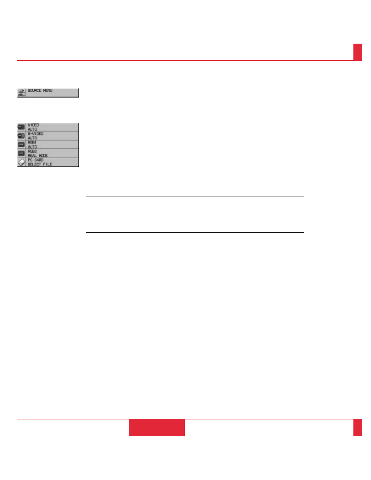
Menu Descriptions & Functions
Source Menu
OPERATION
61
62
Enables you to select a video source such as a VCR, D VD play er, laser disc player, computer
or document camera depending on what is connected to your inputs. Press the "Select"
button on the projector cabinet or (▲) (▼) buttons on your remote control to highlight the
menu for the item you want to adjust
Video
Selects what is connected to your Video input-VCR, laser disc player, DVD player, or
document camera.
S-Video
Selects what is connected to your S-Video input-VCR, DVD player, or laser disc player.
RGB 1
Selects the computer connected to your RGB 1 input.
RGB 2
Selects the computer connected to your RGB 2 input.
NOTE: Normally select the Auto mode so that the LCD projector automatically can select
the appropriate resolution mode for your RGB source.
If you want to finely adjust the image or if the LCD projector fails to select the appropriate
resolution mode for the RGB source , tur n the Auto mode of f and select the Real mode on the
Resolution item.
PC CARD
This feature enables you to make a presentation using the V iewer function with the optional
MT Viewer board (VK-MT) installed.
Press the Mouse pad (+) or (-) buttons to select "Start" for the image you want to display
first and "Select File" for the file you want to select or "Select Slide" for the image you want
to slide.
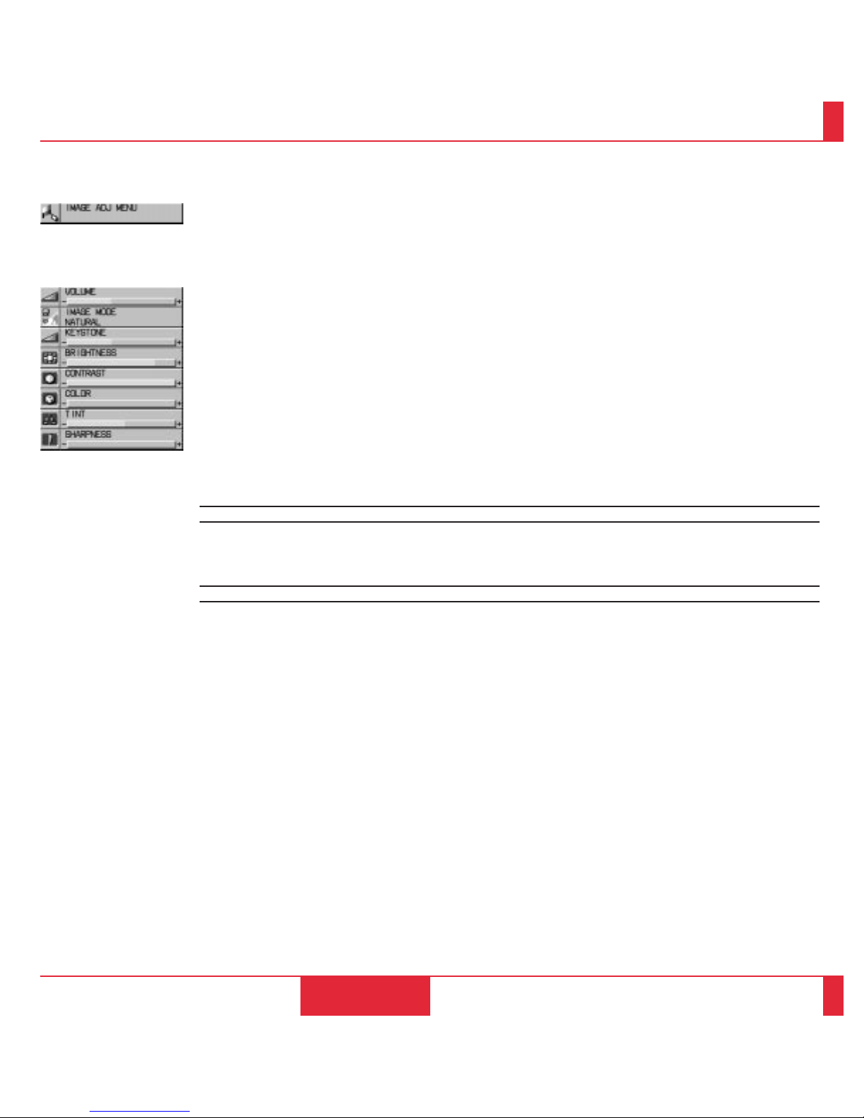
Image Adjustment
Menu
OPERATION
63
64
Provides access to controls for your image and sound. Use the “Select” button on the projector cabinet or (▲)
(▼) buttons on your remote control to highlight the menu for the item you want to adjust.
The volume, image mode, keystone, brightness, contrast, color, tint and sharpness controls are available for
Video or S-Video sources.
The volume, image mode, keystone, brightness, contrast, white balance and auto mode controls are av ailable for
RGB 1 or RGB 2 sources.
The volume, image mode and keystone controls are available for PC CARD.
Volume
Use the Mouse pad (+) or (–) buttons to adjust the volume.
Image Mode
.
VIDEO/S-VIDEO
........ Use the Mouse pad (+) or (-) buttons to choose "Normal" for a regular picture, "Natural"
for true color reproduction, or "Document Camera" for a document camera or other low
APL picture.
RGB/ PC CARD..... Use the Mouse pad (+) or (-) buttons to choose "Normal" when in a lighted room and
"Natural 1&2" when in a darkened room. 1 for better flesh tone; 2 for true reproduction of
middle tones.
Keystone
Use the Mouse pad (+) or (-) buttons to correct the keystone (trapezoidal) distortion to make the top of the
screen longer or shorter to be the same as the bottom.
NOTE: The maximum keystone angle that can be corrected is 23 de grees, including the optical offset 8 de grees.
NOTE: To save your keystone changes, select "Keystone Save" from the Power Menu.
Brightness
Use the Mouse pad (+) or (–) buttons to adjust the brightness.
Contrast
Use the Mouse pad (+) or (–) buttons to adjust the contrast.
Color
..
Use the Mouse pad (+) or (–) buttons to adjust the color.
Tint
..
Use the Mouse pad (+) or (–) buttons to adjust the tint.
Sharpness
..
Use the Mouse pad (+) or (–) buttons to adjust the sharpness.

OPERATION
65
66
White Balance
...
Use the Mouse pad (+) or (-) buttons to adjust the white balance. Brightness for each color (RGB) is used to
adjust the black level of the screen; Contrast for each color (RGB) to adjust the white level of the screen.
Auto Mode
...
Use the Mouse pad (+) button to turn this feature on so "Horizontal Position", "Vertical Position", "Picture
Adjustment", "Fine Picture" and "Resolution" are made automatically. Usually set to ON.
When the Auto mode is turned off with the Mouse pad (-) button is turned off, you can adjust/set "Horizontal Position", "Vertical Position", "Picture Adjustment", "Fine Picture" and "Resolution" manually.
Horizontal Position
...
(when Auto Mode is off)
Use the Mouse pad (+) button to move the image right; (–) to move it left. This adjustment is made automatically when the Auto mode is turned on.
Vertical Position
...
(when Auto Mode is off)
Use the Mouse pad (+) button to move the image up; (–) to move it down. This adjustment is made automatically when the Auto mode is turned on.
Picture Adjustment
...
(when Auto Mode is off)
Use this icon with the “Fine Picture Adjustment” to fine tune the computer image or to remove any vertical
banding that might appear. This function adjusts the c lock frequencies that eliminate the horizontal banding in
the image. Press the Mouse pad (+) and (–) buttons until the banding disappears. This adjustment may be
necessary when you connect your computer for the first time. This adjustment is made automatically when the
Auto mode is turned on.
Fine Picture
...
(when Auto Mode is off)
Use this icon to adjust the clock phase or to reduce video noise, dot interference or cross talk. (This is evident
when part of your image appears to be shimmering.) Use the Mouse pad (+) and (–) buttons to adjust the
image. Use the Fine Adjustment only after the Picture Adjustment is complete. This adjustment is made automatically when the Auto Mode is turned on.
Resolution
...
(when Auto Mode is off)
When "Auto mode" is selected, the LCD projector automatically determines the best resolution for the current
RGB input signal to project an image using NEC's AccuBlend Intelligent Pixel Blending Technology.
Use the Mouse pad (–) button to turn off the Auto mode feature to enable the Resolution feature.
Selecting "Real" allows you to project a source in the real resolution (in the under scan mode) if:
* the LCD projector fails to determine automatically.
* you want to fine adjust an item such as phase.
* you want to project signals other than those with an aspect ratio 4 to 3.
NOTE: Even when you are in the Real mode, an SXGA image is displayed with AccuBlend Intelligent Pixel
Blending Technology.
NOTE:
, The Document Camera mode will not work with an RGB source.
,, Color, Tint, Sharpness and Image Mode controls will not work with an RGB source or PC Card. The
Tint control will not work with a PAL or SECAM source.
,,, Horizontal and Vertical position controls, White Balance, Picture, Fine Picture and Auto Mode
adjustments will not work with a Video, S-Video source or PC card.

Provides access to Lamp Usage information and the Auto Start and Power Management features. Use the “Select” button on the projector cabinet or (▲) (▼) buttons on your remote
control to access a submenu. Then press the Mouse pad (+) or (–) to choose a specific option.
Lamp Usage
This tells you how long the lamp has been in operation. It is recommended that you replace a
lamp after 2000 hours of service. After you install a new lamp, select this icon and press and
hold the “Power On” button on the remote control for ten seconds to reset the lamp clock back
to zero.
NOTE: The projector will turn off and go into stand by mode after 2100 hours of service. If
this happens, press the "Power Off" button on the remote control for ten seconds to reset the
lamp clock back to zero. Do this only after replacing the lamp.
Auto Start
Turns the LCD projector on automatically when the main power switch is turned on. This
eliminates the need to always use the “Power” button on the remote control or projector
cabinet. Press the Mouse pad (+) to turn this feature on and (–) to turn it off.
Power Management
When “Power Off” is on and there is no RGB video input for five minutes or more, the
projector will automatically turn itself off. Press the Mouse pad (+) to turn this feature on and
(–) to turn it off. This feature does not work with Video or S-Video sources.
Power Menu
OPERATION
67
68
Keystone Save
This enables you to save your current keystone settings. Sa ving your change once affects all
sources.
Use the Mouse pad (+) button to turn the feature on so you save the keystone adjustments;
(-) to turn the feature off so you can cancel them.
On Screen Mute
Use the Mouse pad (+) button to turn off the on screen ; (-) to restore it. The On screen Mute
feature is valid for turning on and switching inputs only.

Settings Menu
Enables you to set preferences and other operating options. Use the “Select” button on the projector cabinet or
(▲) (▼) buttons on your remote control to access the submenu you want.
Capture (with the optional viewer board installed only)
When the Capture is selected, press "Enter" on the projector cabinet or Left Click button on the remote control to
display "Execute" and "capture" an image from a source that is currently being displayed. When capturing is
completed, "Completed" is displayed under the Capture icon.
Unless a flash memory card is inserted into the slot of the viewer board, "No Card" is displayed. This means that
the Capture feature is not available. The "Card Error" display means that the free space of the f lash memory card
is insufficient for saving images. Make more space available on the card by erasing unwanted images with your
PC. The number of images that can be captured depends on the size of the flash memory card.
NOTE: Be sure not to turn off the power or remove the flash memory card unless "Completed" is displayed.
Doing so could cause a loss of the data in the flash memory card or damage to the card itself.
Background
Use this feature to display a black or blue screen when no signal is available. Press the Mouse pad (+) or (–)
buttons to choose the back screen you want. Press "Enter" on the cabinet or the "Left Click" on your remote
control to save your change.
OPERATION
69
70
Video Standard
This feature enables you to select composite video standards M_NTSC manually. Normally select "Auto".
Use the Mouse pad (+) or (–) buttons to choose M_NTSC. Press "Enter" on the cabinet or the "Left Click" on
your remote control to save your change.
Projection
This reorients your image for your type of projection. Press the Mouse pad (+) or (–) button until it is correct.
Press “ENTER” on the cabinet or the “Left Click” on your remote control to save your change. The options are:
front floor projection, rear ceiling projection, rear floor projection, and front ceiling projection.
Language
Use the Mouse pad (+) or (–) to choose one of six languages for on-screen instructions. Press “ENTER” on the
cabinet or the “Left Click” on your remote control to save your change The options are: English, German,
French, Italian, Spanish and Swedish.
Pointer
This enables you to select from eight different Pointer icons for the "Pointer" button on your remote control. The
magnifying glass pointer is selected at the factory. Use the Mouse pad (+) or (-) buttons to choose one of the
eight Pointer icons. Press "Enter" on the cabinet or the "Left Click" on your remote control to save your change.
After moving your Pointer icon to the area you want on the screen, press the Magnify button on the remote
control to enlarge the selected area on the screen.
Reset
Changes all adjustments to the factory preset levels for each source individually. To activate, you must hold
down the Mouse pad (+) button on the cabinet or remote control for at least two seconds. The adjustments that
will be reset are white balance, horizontal and vertical control, picture and fine picture adjustment (for the
current source only), white balance, brightness, contrast, color, tint, and sharpness.

Using the Viewer function
If you use the Viewer function on the LCD projector, you must first
install the optional MT Vie wer board (VK-MT) in the LCD projector
and set up the exclusive software included with the VK-MT kit.
See the user's manual included with the VK-MT for installing and
uninstalling the software.
Mounting the Optional MT Viewer Boar d
To install the Vie wer boar d:
1. Set the LCD projector on end with the carrying handle up.
NO TE: Be sure to unplug the LCD projector befor e installing the Viewer board .
2. Remove the two screws from the bottom.
3. Remove the slot cover by pushing up on the catc h of the cov er
with a flat-head screwdriver until you feel it detach.
4. Insert the optional viewer board into the slot. Be sure to push the
board until the board is securely fitted.
5. Secure the board in place with the two screws that you removed in
step 2.
6. Put the LCD projector back in the original position.
71
72
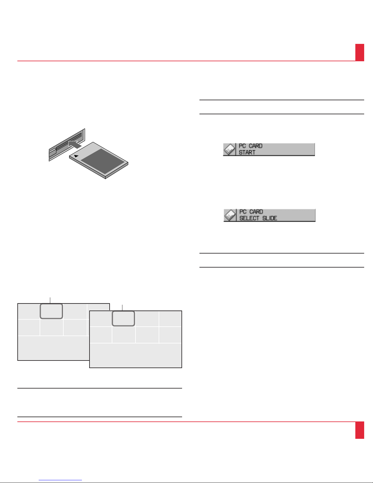
Projecting Slides
Orientation of flash memory car d insertion
The flash memory card has a front and a back side and the flash memory
card is designed to be inserted in only one orientation. The card is
designed so that it cannot be inserted in reverse, but trying to insert it
forcefully might break the pins inside the slot or ruin the flash memory
card slot. See the flash memory card manual for information about the
orientation of the flash memory card.
PCMC IA-ATA
Flash Memory Card
4. Select a file or a slide.
Use the Mouse pad (+) or (–) button on the remote control to select
the file or slide you want to display and press the Enter button on
the cabinet or the Left Click button on the remote control. See the
following pages for more details.
* The type of flash memory card required for use in the LCD projector
is a Type II PCMCIA-ATA flash memory card (not supplied). Ne ver
use other types of PC card than this. Doing so can break the slot or ruin
the PC card.
To Project the Slides (the presentation materials)
1. Insert a flash memory card into the PC card slot.
* To eject the flash memory card , press the Eject button.
NOTE: Should the card be difficult to insert, do not forcefully push
the card in.
2. Select the PC card as a source.
* Press the Menu button on the remote control or projector cabinet
and select "PC CARD" from the Source menu.
* If there is no flash memory card in the card slot, the LCD projector
displays a blue back or black back image.
3. Select "Select File" or "Select Slide".
* Use the Mouse pad (+) or (-) button on the remote control to select
"Select File" or "Select Slide".
* The selected file or slide will be displayed.
NOTE: If you select "Start" and press the Enter button on the cabinet
or the Left Click b utton on the remote contr ol, the slides will be looped.
To use the Start feature, you must first set on the software included
with the MT Viewer board.
8
7
5
6
4
31
2
File
File
File
File
File
File
File
File
Multi Cursor
73
74
NOTE: The Mouse pad (+) or (–) button is valid only when the Menu
button is lit.
H
G
E
F
D
CA
B
presentation
presentation
presentation
presentation
presentation
presentation
presentation
presentation
Table Cursor

Selecting a File from a List of Files
*
The Viewer f eature allo ws you to store one or more presentation materials in a
single flash memory card. Each material is referred to as a "file" or "slide".
To select a file from a list of files
1.Press the Menu button on the remote control or cabinet to select "PC
Card".
H
GE
F
D
C
A
B
presentation
presentation
presentation
presentation
presentation
presentation
presentation
presentation
Table Cursor
NOTE: A maximum of 16 indexes can be switched with "Select F ile".
The last displayed file, which is always exclusively for use of Captur e,
will be displayed during capturing only.
When 17 or more indexes exist n the flash memory card and you wish
to display them, move the index to be displayed to the beginning of
the file inde xes with "Editing file indexes" under "F iles" of the software
for V ie wer.
8
75
6
4
31
2
File
File
File
File
File
File
File
File
Selecting a Slide from a List of Slides (Table)
To select a slide from a list of slides
1.Press the Menu button on the remote control or cabinet to select
"PC Card".
3.Use the Mouse pad (+) or (–) button on the remote control to move
the Table-Cursor (yellow bo x) to the slide you want to display and
press the Enter button on the cabinet or the Left Click button on the
remote control.
* This will display the selected slide.
75
76
Multi Cursor
3.Use the Mouse pad (+) or (–) button on the remote control to move
the Multi-Cursor (blue box) to the file you w ant to display a slide
from, and press the Enter button on the cabinet or the Left Click
button on the remote control.
2. Use the Mouse pad (+) or (-) button on the remote control to select
"Select File" and press the "Enter" button on the cabinet or the Left
Click button on the remote control.
* This will display the first slide of the selected file.
2. Use the Mouse pad (+) or (-) button on the remote control to select
"Select Slide" and press the "Enter" button on the cabinet or the Left
Click button on the remote control.
NOTE: The Slide (+) and (-) button on the remote control can be
also used to select a file or slide, or to turn pages.
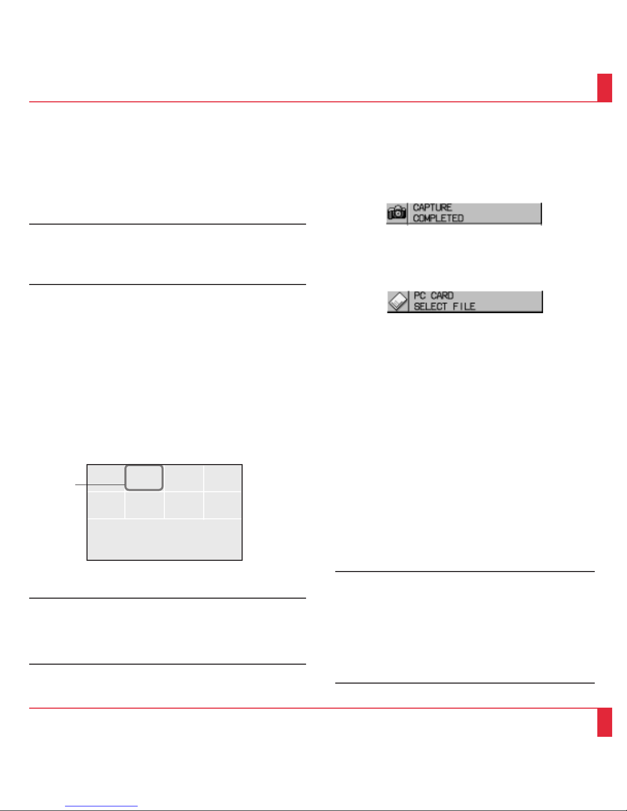
Switching Slides
T o switc h slides, press "SLIDE +" or "SLIDE -" button. This will cancel
the Auto Play mode. To set the Auto Play mode, press the Menu button
to select “Start” from the Source menu and press the Enter button on the
cabinet or the Left Click button on the remote control. This is v alid only
when the Auto Play mode is selected . See more information about “ Auto
Play mode” for the Help file included with the V iewer board.
* SLIDE- returns to the previous slide.
SLIDE+ advances to the ne xt slide.
NO TE: Editing tasks such as deleting the data inside the f lash memory
card cannot be accomplished with the LCD projector. Use the
exclusive software on your PC for this purpose. If you accidentally
delete data required for playback, playing back the data is not
possible.
Effect Sound
The Vie wer function allo ws you to play back effect sound for the slide.
Playing back effect sound can be accomplished during the switching
slides or files only. To use this feature, you must first specify the effect
sound with the supplied software.
You can adjust v olume by using the Volume button.
Capturing the currently displayed screen image
The Vie wer feature allows you to capture a scr een image and store
it to a flash memory card.
To capture a screen image and store it to a flash memory card;
Select "Capture" from the Settings menu and press the Enter button
on the cabinet or Left Click button on the remote control.
* To view the captured image
1.Select "Select File" from the Source menu and display a list of
files.
* A thumbnail (reduced image) of the first captured image will be
displayed.
2.Use the Mouse pad (+) button to move the Multi-Cursor (blue box) to
the last file and press the Enter b utton on the cabinet or the Left Click
button on the remote control.
* This will display the image you captured first.
NOTE: The menu indicating that capturing is now performing will
be displayed during capturing. During this time do not remove the
flash memory card nor turn off the po wer of the LCD pr ojector. Doing
so may destroy the data of the flash memory card.
* When the flash memory card becomes full, replace a new one.
Projecting Pictures a Digital Camera T ook
Playing back on the LCD projector is possible if a picture meets one
of the following requirements:
* A picture that can be stored to an MS-DOS-formatted ATA flash
memory card
* A picture that can be stored as a compatible format
The on-board Viewer searches for the directory on the card to
recognize a JPEG or BMP format image as slide. Directories to be
searched for are up to two level from the r oot directory and must be
less than 16 directories. Although only switching folders and slides
is possible, special effects and displaying a list is not possible.
NOTE:
* Up to 128 images can be recognized as slides for one director y.
* To use special eff ects, read ima ges fr om a flash memory car d and
edit them using the supplied softwar e, then store them to another
flash memory card.
* If you store indexes to the flash memory card for your digital
camera using the supplied software , images taken with the digital
camera cannot be viewed on the Viewer. So preparing flash
memory cards for a digital camera and Viewer respectively is
recommended.
77
78
8
75
6
4
3
1
2
File
File
File
File
File
File
File
File
Multi Cursor

This section describes the simple maintenance procedures you should follow
to replace the lamp, clean or replace the filter, and replace the batter ies in the
remote control.
Replacing The Lamp
After your lamp has been operating for 2000 hours or longer, the
“status” light in the cabinet will go on. Even though the lamp may still
be working, replace it at 2000 hours to maintain optimal projector
performance.
CAUTION
• DO NOT TOUCH THE LAMP immediately after it has been used. It will
be extremely hot. Allow at least one hour for the lamp to cool before
handling.
• DO NOT REMOVE ANY SCREWS except the lamp cover set screw
and two lamp case screws. You could receive an electric shock.
• Turn off the main power to the projector and disconnect the power cord.
Allow at least one hour for the lamp to cool.
• The projector will turn off and go into stand by mode after 2100 hours of
service. If this happens, be sure to replace the lamp. If you continue to
use the lamp after 2000 hours of use, the lamp bulb may shatter, and
pieces of glass may be scattered in the lamp case. Do not touch them as
the pieces of glass may cause injury. If this happens, contact your NEC
dealer for lamp replacement.
MAINTENANCE
4
To replace the lamp:
1. Loosen the single screw that secures the lamp housing cover and remove
the cover.
2. Loosen the two screws securing the lamp case.
3. Remove the lamp by pulling out the complete assembly.
4. Install a new lamp case assembly and secure it in place with the two screws.
CAUTION: Do not use a lamp other than the NEC replacement lamp.
Order this from your NEC dealer using your projector's model number .
5. Reattach the lamp cover and tighten the single scre w.
6. After you install a new lamp, select the lamp Usage icon and press and hold
the "Power On" button on the remote control for ten seconds to reset the
lamp time clock to zero.
NOTE: If resetting the lamp clock back to zero after 2100 hours of service,
pr ess the "Power Off" (not "Power On") button on the remote control for ten
seconds .
NOTE: When you replace the lamp, it is also wise to replace the filter. The
filter comes in the same package with your replacement lamp.
Step 1A
Step 1B
Step 2
Step 3
Step 4
Step 5
MAINTENANCE
79
80

Cleaning Or Replacing The Filter
The air-f ilter sponge keeps the inside of the MultiSync MT830/1030 LCD Projector free from dust or
dirt and should be cleaned after ev ery 100 hours of operation (more often in dusty conditions). If the
filter is dirty or clogged, your projector may ov erheat.
NOTE: Clean your filter after every 100 hours of operation.
CAUTION
• Turn off the main power and unplug the projector before replacing the filter.
• Only clean the outside of the filter co ver with a v acuum cleaner.
• Do not attempt to operate the projector without a filter cover.
• Your LCD projector will not operate unless the filter cover is installed correctly.
To clean the air-filter:
Vacuum the filter through the filter cover.
To replace the air-filter:
1. Remove the filter co ver b y pushing up on the catch of the cover with a f lat-head screwdri ver until
you feel it detach.
2. Reinstall the new filter cover.
NOTE: Do not detach the sponge from the filter cover. Do not wash the filter cover with soap and
water. Soap and water will damage the filter membrane.
Before replacing the filter cover, remove dust and dirt from the projector cabinet. Keep out
dust and dirt during filter replacement.
Remote Control Battery Installation
1. Press firmly and slide the battery cov er off.
2. Remove both old batteries and install new ones (AA). Ensure that you have the batteries' polarity
(+/–) aligned correctly.
3. Slip the cover back over the batteries until it snaps into place.
MAINTENANCE
81
82

Etape 1A
Etape 1B
Etape 2
Etape 3
Etape 4
Etape 5
MAINTENANCE
83
84
Cette section décrit les procédures simples d’entretien que vous aurez à suivre pour
remplacer la lampe, nettoyer ou remplacer le filtre et remplacer les piles de la télécommande.
Remplacement de la lampe
Lorsque la lampe a été utilisée pendant 2000 heures ou plus, le voyant “Status” (état) du
coffret s’allume. Même si la lampe peut encore fonctionner, remplacez-la au bout de
2000 heures pour conserver une performance optimale de votre projecteur.
PRECAUTIO N
•
NE TOUCHEZ PAS A LA LAMPE juste après qu’elle a été utilisée. Elle est très
chaude. Laissez-la refoidir pendant au moins une heure avant de la manipuler.
• NE RETIREZ AUCUNE VIS mis à part la vis qui fixe le couv ercle de lampe
et les deux vis du compartiment de lampe. Vous risquez de recevoir une
décharge éléctrique.
• Mettez le projecteur hors circuit et débranchez le cordon d’alimentation.
Laissez refroidir la lampe pendant au moins une heure.
• Le projecteur s’éteindra et restera en attente après 2100 heures d’utilisation.
Dans ce cas, remplacez la lampe. Si vous continuez d’utiliser la lampe après
2000 heures d’utilisation, l’ampoule peut se briser et des brisures de verre
peuvent être éparpillées dans le compartiment de la lampe. Ne les touchez pas
car elles peuvent vous blesser. Dans ce cas, contactez votre rev endeur NEC
afin de procéder au remplacement de la lampe.
Pour remplacer la lampe :
1.
Desserrer l’unique vis qui fixe le couvercle de lampe et retirez le couvercle.
2.
Desserrer les deux vis qui fixent le compartiment de lampe.
3. Retirez la lampe en tirant tout l’assemblage.
4.
Installez un nouvel assemblage de compartiment lampe et fixez-le avec les deux vis.
PRECAUTION: N’utilisez pas d’autres lampes qu’une lampe de
rechange NEC.
Commandez-la auprès de votre vendeur NEC en donnant le numéro
de modèle du projecteur.
5. F ixez de nouveau le couvercle de lampe et serrer la vis unique.
6.
Une fois la nouvelle lampe installée, sélectionnez l’icone d’utilisation de lampe
et appuyez et maintenez la touche “Power On” (alimentation activée) de la
télécommande pendant dix secondes afin de remettre à zéro l’horloge de lampe.
REMARQUE: Pour remettre à zéro l’horloge de lampe après 2100 heures
d’utilisation, appuyez sur la touche “Power Off” (alimentation désacti vée)(et
non “Power On” (alimentation activée)) de la télécommande pendant dix
secondes .
REMARQUE: Lorsque vous remplacez la lampe, il est recommandé de
changer également le filtre. Le f iltre se trouve dans le même emballa ge que
la lampe de rechange.
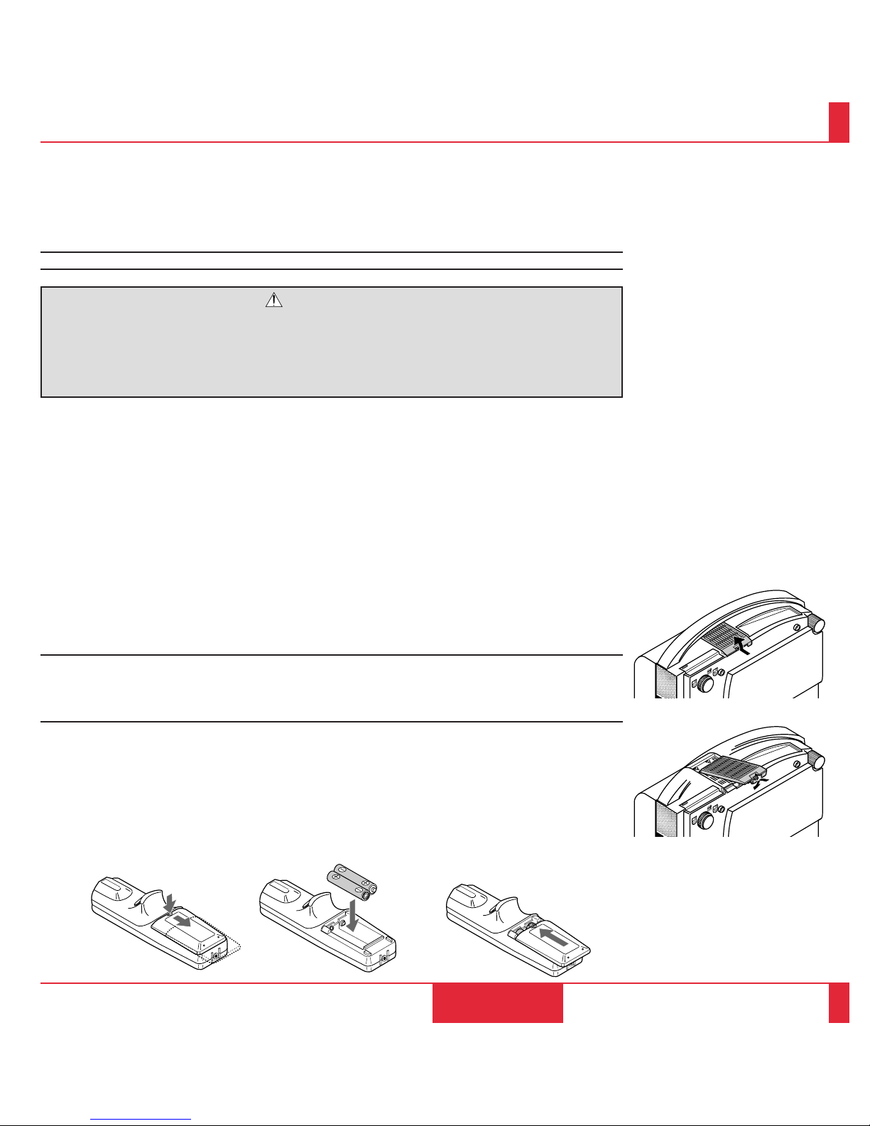
MAINTENANCE
85
86
Nettoyage ou remplacement du filtre
Le coussin éponge du filtre à air maintient l’intérieur du projecteur à affichage à cristaux liquides
MultiSync MT830/1030 à l’abri de la poussière ou de la saleté et doit être nettoyé toutes les 100 heures
d’utilisation (plus souvent dans les endroits poussiéreux). Si le filtre est sale ou bouché, le projecteur
risque de surchauffer.
REMARQUE: Nettoyez le filtre toutes les 100 heures d’utilisation.
PRECAUTION
• Couez l’alimentation et déranchez le projecteur avant de remplacer le filtre.
• Nettoyez uniquement le couvercle extérieur du filtre avec un aspirateur.
• N’essayez pas de faire fonctionner le projecteur sans couvercle de filtre.
• V otre projecteur à af fichage à cristaux liquides ne fonctionnera pas tant que le couvercle de filtre ne
sera pas installé correctement.
Pour nettoyer le filtre à air:
Aspirez le filtre à travers le couvercle de filtre.
Pour remplacer le couvercle de filtre:
1.Retirez le couvercle de filtre en poussant v ers le haut sur le cliquet du couvercle à l’aide d’un tourne vis
à tête plate jusqu’à ce que vous sentiez qu’il se détache.
2.Réinstallez le nouvel couvercle de filtre.
NOTE: Ne détachez pas le coussin éponge du couvercle de filtre. Ne lavez pas le filtre au savon et à
l’eau. Le savon et l’eau endommageront la membrane du filtre.
Avant de remplacer le filtre à air, dépoussiérez et nettoyez le coffret du projecteur. Maintenez propre
pendant le remplacement du filtre.
Installation des piles de la télécommande
1. Appuyez fermement et r etirez le couvercle des piles en le faisant glisser.
2. Retirez les deux piles usagées et installez de nouvelles piles (AA). Assurez-vous de respecter la
polarité (+/–) des piles.
3. Remettez le couvercle des piles en le faisant glisser, jusqu’à ce qu’il s’emboîte.

This section helps you resolve problems you may encounter while setting up or using your MultiSync MT830/1030 LCD Projector.
Status Light Messages
TROUBLESHOOTING5
TROUBLE SHOOTING
87
88
Status
m Normal
m The projector lamp has exceeded 2000 hours of operation and
should be replaced.
m Either the lamp cover or filter cover is not fastened properly. Check
each and reattach them if necessary.
m The cooling fan has stopped. Contact your NEC dealer for service.
m The lamp is not turned on.
• The projector was turned off and back on too quickly. Turn
off the projector, wait one minute, then turn the projector
back on. Or the lamp is burnt out.
Condition
OFF
On continually
Blinking very rapidly
(On and off in a c ycle of 1 sec.)
Blinking slowly
(On and off in a cycle of 8 sec.)
Blinking very slowly
(On and off in a cycle of 12 sec.)

Common Problems & Solutions
Problem
Does not turn on
No picture
Image isn’t square to the screen
Picture is blurred
Image is scrolling vertically,
horizontally or both
Remote control does not work
Check These Items
• Check that the cord is plugged in and that the power switch on the front panel is on.
• Ensure that the filter cover is installed correctly. (See page 82.)
• Check to see if the projector has overheated or the lamp usage exceeds 2100 hours. If there is insufficient ventilation around the
projector or if the room where you're presenting is particularly warm, move the projector to a cooler location.
Check the filter and clean it if necessary.
• Use the menu icons to select your source (Video, S-Video, RGB1, 2 or PC Card). (See pages 61 and 62.)
• Ensure your cables are connected properly.
• Use icons to adjust the brightness and contrast.
• Remove the lens cap.
• Reset the settings or adjustments to factory preset levels using the RESET icon on the Settings Menu.
• Reposition the projector to improve its angle to the screen.
• Use the keystone icon or the keystone button to correct the keystone distortion.
• Adjust the focus. (See page 20 or 29.)
• Reposition the projector to improve its angle to the screen.
• Ensure that the distance between the projector and screen is within the adjustment range of the lens.
• Use icons to select the source you want to input.
• Make sure the recalled Custom Memory supports the current input signal.
• Install new batteries. (See page 82 or 86.)
• Make sure there are no obstacles between you and the projector.
• Stand within 23 feet (7m) of the projector.
To Contact Your NEC Ser vice Representative, Call 1-800-836-0655
TROUBLE SHOOTING
89
90
When using the Viewer function
Problem
No picture
Part of a slide is not
displayed
No effect sound
Check These Items
• Is the viewer board been seated in the LCD projector completely?
• Is "PC CARD" selected from the Source menu?
• Is the flash memory card seated in the card slot completely?
• Are slide data being transferred to the flash memory card?
• Have the contents of the flash memory card been destroyed?
• While an image with over 10242768 dots is projected, several lines of information will be lost. Use the supplied software to
change the image to 10242768 dots in size.
• Is the sound volume set to the minimum level?
Problem
Status indicator is lit or
blinking
Cross color in RGB mode
Check These Items
See the Status Light message chart on pages 87 and 88.
If “Auto Picture” is off, turn it on. If “Auto Picture” is on, turn it off and balance the image with the Picture Adjustment icon and
Fine Picture Adjustment icon.

This section provides technical information about the MultiSync MT830/1030 LCD Projector's performance.
Optical
LCD Panel
1.3", p-Si TFT acti ve-matr ix, 8002600 dot (MT830) / 1024 2768 dot (MT1030)
Lens Power zoom, power f ocus
F 2.5 f =52 – 68 mm
Lamp New short arc high pressure lamp 150 W
(Guaranteed life span: 2,000 hours or
6 months from date of purchase,
whichever comes first.)
Image Size 20-300 inches diagonal
Projection Distance 3.28 – 40.03 ft (1.0 – 12.2 m)
SPECIFICATIONS6
Electrical
Inputs Video (NTSC / P AL / SECAM / NTSC4.43)
RGB (H : 15 – 85 kHz, V : 50 – 85 Hz)
Video Bandwidth RGB: 80 MHz
Color Reproduction Full color, 16.7 million colors simultaneously .
Horizontal Resolution 550 TV lines at S-Video : NTSC,
350 TV lines : PAL / SECAM / NTSC 4.43
RGB 800 dots horizontal, 600 dots vertical (MT830)
1024 dots horizontal, 768 dots vertical (MT1030)
Power Requirement 100 – 120 / 220 – 240 VAC, 50 / 60 Hz
Input Current 3.5 A / 1.5A
Mechanical
Dimensions 13.2" (W)25.8" (H)215.6" (D)
33.5 cm (W)214.8 cm (H)239.6 cm (D)
Net Weight 16.1 lbs / 7.3 kg
Operational Temperatures LCD projector: 32° – 104°F(0° to 40 °C), 20 – 80% humidity
Remote control: 32° – 140°F (0° to 60°C)
Remote mouse receiver: 32° – 140°F (0 ° to 60°C)
Regulations UL Approved (UL 1950, CSA 950)
Meets DOC Canada requirements
Meets FCC Class A requirements
SPECIFICATIONS
91
92

11.4"
(290)
14.9"
(378.0)
15.6"
(396.0)
MENU
SELECT
ENTER
ZOOM FOCUS
ON/OFF
STATUS
POWER
–
+–+
–
+
PC CONTROLMOUSE OUTP
U
RGB INPUT 2AUDIORGB INPUT 1
AUDIORGB MONITOR OUTPUT
RL/MONO
INPUT AUDIOS–VIDEO
RL/MONO
INPUT AUDIOVIDEO
Cabinet Dimensions
Unit : inch (mm)
SPECIFICATIONS
93
94
7"
(178.5)
13.1"
(332)
3.63"
(92.2)
5.8"
(148.0)
T
PUT
REMOTE
CONTROL
INPUT
AUDIO
AC IN

D-Sub Pin Assignments
PC 15-Pin mini D-Sub
1
2
34
5
11
12
13
1415
6
7
8
9
10
PC 15-Pin mini D-Sub
SPECIFICATIONS
95
96
Pin No. Signal to be connected
1 Red
2 Green
3 Blue
4 GND
5 GND
6 Red GND
7 Green GND
8 Blue GND
9 No Connection
10 Digital GND
11 GND
12 No Connection
13 Horizontal Sync
14 Vertical Sync
15 No Connection

Timing Chart
Y/N Signal Resolution Refresh F.H. Dot
Rate (Hz) (kHz) Clk(MHz)
Y NTSC 6402480 60 15.734 Y PAL 7682576 50 15.625 Y SECAM 7682576 50 15.625 Y VESA 6402350 85.08 37.86 31.5
Y IBM 6402400 70 31.47 25.175
Y VESA 6402400 85.08 37.86 31.5
Y MAC 6402400 66 35 30.24
Y VESA 6402480 59.94 31.47 25.175
Y IBM 6402480 60 31.47 25.175
Y MAC 6402480 60 31.47 25.175
Y MAC 6402480 66.7 34.97 31.334
Y MAC 6402480 66.67 35 30.24
Y VESA 6402480 72.81 37.86 31.5
Y VESA 6402480 75 37.5 31.5
Y IBM 6402480 75 39.375 31.49
Y VESA 6402480 85.01 43.269 36
Y IBM 7202350 70.09 31.469 28.322
Y IBM 7202400 70.09 31.4469 28.322
Y VESA 7202400 85.04 37.927 40
Y IBM 7202350 87.85 39.44 35.5
Y IBM 7202400 87.7 39.375 35.5
Y VESA 8002600 56.25 35.16 36
Y VESA 8002600 60.32 37.879 40
Y VESA 8002600 72.19 48.077 50
Y VESA 8002600 75 46.88 49.5
Y VESA 8002600 85.06 53.674 56.25
Y MAC 8322624 74.55 49.725 57.283
N VESA 10242768 43interlace 35.5 44.9
Y VESA 10242768 60 48.363 65
Y VESA 10242768 70.07 57.476 75
Y IBM 10242768 72.03 58.131 79
Y MAC 10242768 74.93 60.241 80
Y VESA 10242768 75.03 60.023 78.75
Y VESA 10242768 85 68.677 94.5
Y SGI 10242768 60.4 49.7 70
# MAC 11522870 75.6 68.7 100
# SUN 11522900 69.95 61.769 92.94
# SGI 11522900 76.05 71.736 105.6
# SGI 128021024 60 63.9 107.35
# VESA 128021024 60.04 64.286 108
# MAC 128021024 69.89 74.882 118.5
# HP 128021024 72.01 78.125 135
# VESA 128021024 75.03 79.976 135
# SUN 128021024 76.11 81.13 135
SPECIFICATIONS
97
98
# 11522870, # 11522900 and # 128021024
images are compressed into 10242768 on
MT1030 with AccuBlend ; 8002600 on MT830
with AccuBlend
10242768 and 8322624 images are compressed
into 8002600 on MT830

PC Control Command Reference
Command Codes
No. Function Code Data Description
01 V ideo 03H No Same as remote
02 RGB1 04H No Same as remote
03 RGB2 05H No Same as remote
04 S-VIDEO C6H No Same as remote
05 PC CARD 27H No Same as remote (av ailable only when the V iewer board is installed)
06 Power On 08H No Same as remote (See NOTE on page 104.)
07 Power Of f 14H No Same as remote
08 Picture Mute 47H No Same as remote
09 Onscreen Mute 11H No
10 Power Zoom W 09H No Same as remote
11 Power Zoom T 0AH No Same as remote
12 Power Focus + 0BH No Same as remote
13 Power Focus – 0CH No Same as remote
14 Reset 43H No (Resets immediately after returning ACK)
15 Freeze 4CH No Same as remote
16 Slide + 4BH No Same as remote (available only whenPC CARD is selected)
17 Slide - 20H No Same as remote (available only whenPC CARD is selected)
18 Front Floor 33H No
19 Front Ceiling 34H No
20 Rear Floor 35H No
21 Rear Ceiling 36H No
22 Auto Start On 19H No
23 Auto Start Off 1AH No
24 Image mode Select 1EH Yes 0 to 2 at Video, 3 to 5 at the others
25
Power Management On
15H No
26
Power Management Off
16H No
SPECIFICATIONS
99
100

Command Codes (continued)
No. Function Code Data Description
27 Brightness 60H Yes 0 to 63
28 Contrast 62H Yes 0 to 63
29 Color 64H Yes 0 to 63
30 Tint 66H Yes -32 to +31(E0 to 1F)
31 Sharpness 68H Yes 0 to 3
32 Audio Volume 6AH Yes 0 to 63
33 Picture Adj 70H Yes*
768 to 1279 (2 byte code)
34 Fine Picture 6EH Yes 0 to 31
35 H Position 72H Y es -64 to +63 (C0 to 3F)
36 V Position 74H Y es -32 to +31 (E0 to 1F)
37 Lamp Reset 3FH No
38 Language Select 3DH Yes 00:English, 01:German, 02:French, 03:Italian, 04:Spanish, 05:Swedish
SPECIFICATIONS
101
102
39 White Balance
Sub Brightness R 75 Yes 0 to 7FH
G 76 Yes 0 to 7FH
B 77 Yes 0 to 7FH
Sub Contrast R 78 Yes 0 to 7FH
G 79 Yes 0 to 7FH
B 7A Yes 0 to 7FH
40 Pointer Select 7F Yes 0 to 7
41 Video System 61 Yes 0 to 2 (a vailable only when VIDEO is selected)
These commands are subject to change without notice.
*(Low-order data) (High-order data) CSUM
CSUM = Checksum is a low-order digit of the sum from the Code to the immediately preceding data.

44
Err 04: Parameter Error ( parameter data abnormal)
12
54 3
6
7
8
To RxD of PC
©
PC Control Connector (DIN-8P)
Cable Connection
Communication Protocol
Baud rate: 9600 bps
Data length: 8 bits
Parity: No parity
Stop bit: One bit
X on/off: None
Communications
Full duplex
procedur e:
If the CPU of the LCD projector has received the data correctly, it returns an ACK(C5H). If the received data is not correct, the CPU returns a
NAK(CAH), then the following status:
Receiving success: C5
Receiving failur e: CA Err
Err 01: Command Error (command not supported)
Err 02: Checksum Error
Err 03: Busy (command not acceptable)
NOTE: If failing in powering-on, the CPU returns the following NAKs:
CA Err 1
Err 1 8X (A pply the corr esponding bit.)
Bit 0: Either filter panel or lamp cover is not attached correctly
Bit 1: Fan stoppage
Bit 2: Overheated
Bit 3: Lamp lighting failure
To TxD of PC
§
To GND of PC
©
SPECIFICATIONS
103
104
 Loading...