

NEC M40-2-AV User Manual

External Control NEC LCD Monitor
1. Application
This d ocument defines the communications method for control of the NEC LCD monitor, MultiSync
LCD4020/46 20/5220/6520 and MULTEOS M40/46 when using an external controller
.
2. Connectors and wiring
Connector: D-Sub 9-pin
Cable: Cross (reversed) cable or null modem cable
(Please refer “Using the LCD with RS-232C” on each User’s manual.)
3. Communication Parameter
(1) Communication system Asynchronous
(2) Interface RS-232C
(3) Baud rate 9600bps
(4) Data length 8bits
(5) Parity None
(6) Stop bit 1 bit
(7) Communication code ASCII
3.1 Communication timing
The controller should wait for a packet interval before next command is sent.
The packet interval needs to be longer than 600msec for the LCD monitor.
(1/40)
4. Communication Format
Header
Message
Check Code
Delimiter
Header
Del
imiter
Header
Message
Check Code
Delimiter
Header
Delimiter
Header
Message
Check Code
Delimiter
Header
Delimiter
Header
Message
Check Code
Delimiter
Header Message Check Code Delimiter
The command packet consists of four parts, Header, Message, Check code and Delimiter.
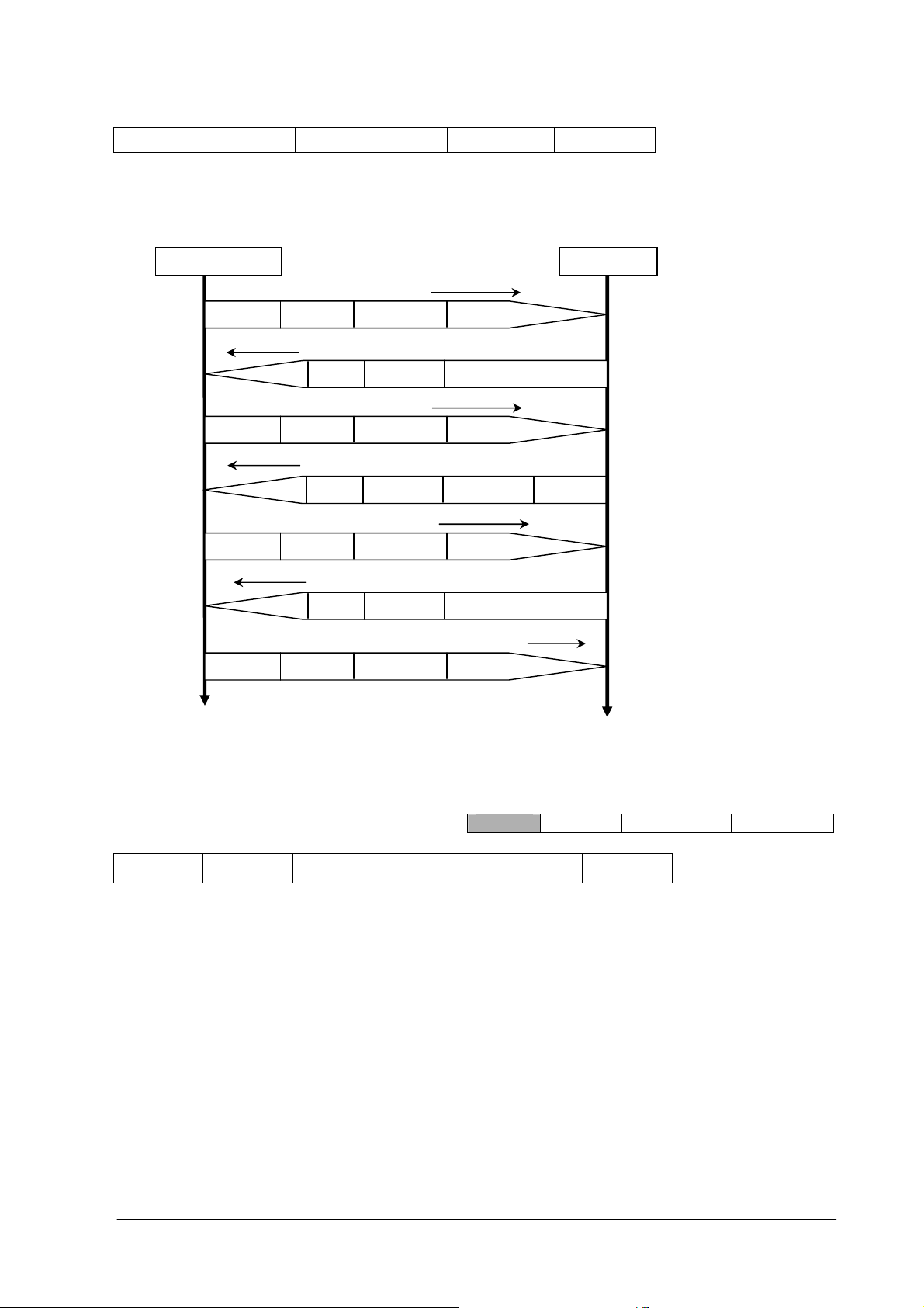
Sequence of a typical procedure to control a monitor is as follows,
[A controller and a monitor, two-way communication composition figure]
Get Parameter
Get Parameter Reply
Message
Check Code
Set Parameter
Set Parameter Reply
Message
Check Code
Get Parameter
Get Parameter Reply
Message
Check Code
Save Current Setting Command
4.1 Header block format (fixed length)
SOH
1st 2nd 3rd 4th 5th 6th -7th
Reserved
'0'
Destination Source
Header
Message
Type
Monitor Controller
The controller send s command to
get a value from the monitor that
you want to change.
The monitor replies a current value
of the requested item.
The controller sends commands to
set an adjusted value.
The monitor replies to the
controller for confirmation.
The controller sends command to
get a value for confirmation.
The monitor replies an adjusted
value.
The controller requests to store
the adjusted value to the monitor.
Message Check code Delimiter
Message
Length
1stbyte) SOH: Start of Header
ASCII SOH (01h)
nd
2
byte) Reserved: Reserved for future extensions.
On this monitor, it must be ASCII '0'(30h).
rd
3
byte) Destination: Destination equipment ID. (Receiver)
Specify a commands receiver’s address.
This value must match the “Monitor ID No.” set in the OSD.
(2/40)

“Monitor ID” to “Destination Address” conversion table is as follows,
Monitor ID Destination
Address (ASCII)
Monitor ID Destination
Address (ASCII)
1 ‘A’(41h) 14 ‘N’(4Eh)
2 ‘B’(42h) 15 ‘O’(4Fh)
3 ‘C’(43h) 16 ‘P’(50h)
4 ‘D’(44h) 17 ‘Q’(51h)
5 ‘E’(45h) 18 ‘R’(52h)
6 ‘F’(46h) 19 ‘S’(53h)
7 ‘G’(47h) 20 ‘T’(54h)
8 ‘H’(48h) 21 ‘U’(55h)
9 ‘I’(49h) 22 ‘V’(56h)
10 ‘J’(4Ah) 23 ‘W’(57h)
11 ‘K’(4Bh) 24 ‘X’(58h)
12 ‘L’(4Ch) 25 ‘Y’(59h)
13 ‘M’(4Dh) 26 ‘Z’(5Ah)
ALL ‘*’(2Ah)
Ex.) If you want to control a monitor that has the "ID No." as '1', specify a destination address
'A'(41h). If you want to control all of the monitors which are connected by a daisy chain, specify
a destination address ‘
*
’(2Ah).
th
4
byte) Source: Source equipment ID. (Sender)
Specify a sender address.
The controller must be ‘0’ (30h).
th
5
byte) Message Type: (Case sensitive.)
Refer to section 4.2 “Message block format” for more details.
ASCII 'A' (41h): Command.
ASCII 'B' (42h): Command reply.
ASCII 'C' (43h): Get current parameter from a monitor.
ASCII 'D' (44h): "Get parameter" reply.
ASCII 'E' (45h): Set parameter.
ASCII 'F' (46h): "Set parameter" reply.
th
6
-7th bytes) Message Length:
Specify the length of the message (that follows the header) from STX to ETX.
This length includes STX and ETX.
The byte data must be encoded to ASCII characters.
Ex.) The byte data 3Ah must be encoded to ASCII characters '3' and 'A' (33h and 41h).
The byte data 0Bh must be encoded to ASCII characters '0' and 'B' (30h and 42h).
4.2 Message block format
Header
Message
Check code Delimiter
“Message block format” is allied to the “Message Type” in the “Header”.
Refer to the section 6 “Message format” for more detail.
(3/40)

1)Get currentparameter
Lo Hi Lo
Hi Lo Hi Lo Hi Lo
The controller sends this message when you want to get the status of the monitor.
For the status that you want to get, specify the “OP code page” and “OP code”,
refer to “Appendix A. Operation code table”.
“Message format” of the “Get current
2
)
Get Parameter reply
The monitor will reply with the status of the requested item specified by the controller
in the “Get parameter message”.
STX
Hi
3
)
Set parameter
The controller sends this message to change a setting of the monitor.
STX
STX
Refer to section 5.1 “Get current parameter from a monitor.” for more details.
“Message format” of the “Get parameter reply” is as follows,
Result
Lo Hi Lo Hi Lo Hi Lo MSB
Refer to section 5.2 “Get parameter reply” for more details.
Message format of the “Set parameter” is as follows,
OP code
page
Hi
Refer to section 5.3 “Set parameter” for more details.
OP code page
Hi Lo Hi Lo
OP code
page
OP code Set Value
OP code Type Max value Current Value
parameter” is as follows,
OP code
MSB
ETX
LSB
ETX
LSB MSB
ETX
LSB
4
)
Set Parameter reply
The monitor replies with this message for a confirmation of the “Set parameter message”.
Message format of the “Set parameter reply” is as follows,
STX
Result
Hi Lo
5
)
Command
“Command message” format depends on each command.
Usually, this “command message” is used for some non-sli der controls and some special o perations,
such as “Save curr ent settings”, “Get timing report”, “power cont rol”, “Schedule”, etc. Refer to
section 5. 5 “Commands message” for more details.
6
)
Command reply
The monitor replies to a query from the controller.
Refer to section 5.4 “Set parameter reply” for more details.
OP code
page
OP code
Type Max value
MSB
LSB MSB LSB
Requested setting
Value
ETX
(4/40)
“Command reply message” format depends on each command.
n+1
Refer to section 5.5 “Commands message” for more details.
4.5 Check code
Header Message
Check code is the Block Check Code (BCC) between the Header and the End of Message except SOH.
27 26 25 24 23 22 21 20
SOH D0
Reserved D1
Destinatio n D2
Source D3
Type D4
Length D5
STX D6
Data D7
| |
| |
ETX Dn
Check code D
P P P P P P P P
D
= D1 XOR D2 XOR D3 XOR ,,, D
n+1
n
XOR: Exclusive OR
Check code
Delimiter
Following is an example of a Check code (BCC) calculation.
Header Message
SOH Reserved
01 30 41 30 45 30 41 02 30 30 31 30 30 30 36 34 03 77 0D
D
0
Destination
Address
D1 D2 D3 D4 D5 D6 D7 D
Source
Address
Message
type
Message length STX
OP code
page
8
OP code Set Value ETX
D
D
D
D
D
9
10
11
12
D
13
14
D
15
Check
Delimiter
code
(BCC)
D
D
16
D18
17
Check code (BCC) D
= D1 xor D2 xor D3 xor … xor D14 xor D15 xor D16
17
= 3 0h xor 41h xor 30h xor 45h xor 30h xor 41h
xor 02h xor 30h xor 30h xor 31h xor 30h xor 30h
xor 30h xor 36h xor 34h xor 03h
= 77h
4.6 Delimiter
Header Message Check code
Delimiter
Packet delimite r code; ASCII CR(0Dh).
(5/40)

5. Message type
5.1 Get current Parameter from a monitor.
STX
OP code page
Hi Lo Hi Lo
1st 2nd-3rd 4th–5th 6
OP code
ETX
th
Send this message when you want to get the status of a monitor.
For the status that you want to get, specify the “OP co de page” the “OP co de”, refer to
A. Operati on code table”.
st
1
byte) STX : Start of Message
ASCII STX (02h)
nd-3rd
2
bytes) OP code page: Operation code page.
Specify the “OP code page” for the control which you want to get the status.
Refer to “Appendix A Operation code table” for each item.
OP code page data must be encoded to ASCII characters.
Ex.) The byte data 02h must be encoded to ASCII characters '0' and '2' (30h
and 32h).
OP code page 02h -> OP code pa ge (Hi) = ASCII '0' (30h)
OP code page (Lo) = ASCII '2' (32h)
“Appendix
STX
st
1
Refer to Operation code table. (Appendix A)
th–5th
4
bytes) OP code: Operation code
Refer to “Appendix A Operation code table” for each item.
OP code data must be encoded to ASCII characters.
Ex.) The byte data 3Ah must be encoded to ASCII characters '3' and 'A' (33h and 41h).
OP code 3Ah -> OP code (Hi) = ASCII '3' (33h)
OP code (Lo) = ASCII 'A' (41h)
Refer to Operation code table.
th
6
byte) ETX: End of Message
ASCII ETX (03h)
5.2 "Get parameter" reply
Result OP code page OP code
Hi Lo Hi Lo Hi Lo Hi Lo MSB
2nd-3rd 4th–5th 6th –7th 8th -9
Type Max value Current Value
th
10th -13th 14th -17th 18th
LSB MSB
LSB
The monitor replies with a current value and the status of the requested item (operation code).
st
1
byte) STX: Start of Message
ETX
ASCII STX (02h)
nd-3rd
2
bytes) Result code.
(6/40)

These bytes indicate a result of the requested commands as follows,
00h: No Error.
01h: Unsupporte d operation with this moni tor or unsupported operation under current condition.
This result code from the monitor is encoded to ASCII characters.
Ex.) The byte data 01h is encoded to ASCII character '0' and '1' (30h and 31h).
th–5th
4
bytes) OP code page: Operation code page.
These bytes indicate a replying item's OP code page.
This returned value from the monitor is encoded to ASCII characters.
Ex.) The byte data 02h is encoded to ASCII character '0' and '2' (30h and 32h).
Refer to the operation code table.
th
6
–7thbytes) OP code: Operation code
These bytes indicate a replying item's OP code.
This returned value from the monitor is encoded to ASCII characters.
Refer to the operation code table.
Ex.) The byte data 1Ah is encoded to ASCII character '1' and 'A' (31h and 41h).
th
8
-9thbytes) Type: Operation type code
00h: Set parameter
01h: Momentary
Like the Auto Setup function which automatically changes the parameter.
This returned value from the monitor is encoded to ASCII characters.
Ex.) The byte data 01h is encoded to ASCII character '0' and '1' (30h and 31h).
th
10
-13thbytes) Max. value: Maximum value which monitor can accept. (16bits)
This returned value from the monitor is encoded to ASCII characters.
Ex.) '0','1','2' and '3' means 0123h (291)
th
14
-17thbytes) Current Value: (16bits)
This returned value from the monitor is encoded to ASCII characters.
Ex.) '0','1','2' and '3' means 0123h (291)
th
18
byte) ETX: End of Message
ASCII ETX (03h)
5.3 Set parameter
th
STX
st
1
OP code page
OP code
Hi Lo Hi Lo MSB
Set Value
LSB
2nd-3rd 4th-5th 6th-9th 10
ETX
Send this message to change monitor’s adjustment and so on.
The controller requests a monitor to change value.
st
1
byte) STX: Start of Message
ASCII STX (02h)
nd-3rd
2
bytes) OP code page: Operation code page
(7/40)

This OP code page data must be encoded to ASCII characters.
Hi Lo Hi
Ex.) The byte data 02h must be encoded to ASCII '0' and '2' (30h and 32h).
Refer to the Operation code table.
th-5th
4
bytes) OP code: Operation code
This OP code data must be encoded to ASCII characters.
Ex.) OP code 1Ah -> OP code (Hi) = ASCII '1' (31h)
OP code (Lo) = ASCII 'A' (41h)
Refer to the Operation code table.
th-9th
6
bytes) Set value
: (
16bit)
This data must be encoded to ASCII characters.
Ex.) 0123h -> 1
2
3
4
th
10
byte) ETX: End of Message
st
(MSB) = ASCII '0' (30h)
nd
= ASCII '1 ' (31h)
rd
= ASCII '2 ' (32h)
th
(LSB) = ASCII '3 ' (33h)
ASCII ETX (03h)
STX
st
1
5.4 "Set parameter" reply
Result OP code page
Lo Hi Lo Hi Lo MSB
OP code
Type Max value
LSB MSB
2nd-3rd 4th-5th 6th-7th 8th-9th 10th-13th 14th -17th 18
The Monitor echoes back the parameter and status of the requested operation code.
st
1
byte) STX: Start of Message
ASCII STX (02h)
nd-3rd
2
bytes) Result code
ASCII '0''0' (30h, 30h): No Error.
ASCII '0''1' (30h, 31h): Unsupported operation with this monitor or unsupported operation under
current condition.
th-5th
4
bytes) OP code page: Echoes back the Operation code page for confirmation.
Reply data from the monitor is encoded to ASCII characters.
Ex.) OP code page 02h -> OP code page = ASCII '0' and '2' (30h and 32h)
Refer to Operation code table.
th-7th
6
bytes) OP code: Echoes back the Operation code for confirmation.
Requested setting
Value
LSB
ETX
th
Reply data from the monitor is encoded to ASCII characters.
Ex.) OP code 1Ah -> OP code (Hi) = ASCII '1' (31h)
OP code (Lo) = ASCII 'A' (41h)
Refer to Operation code table
th-9th
8
bytes) Type: Operation type code
(8/40)

ASCII '0''0' (30h, 30h): Set parameter
ASCII '0''1' (30h, 31h): Momentary
Like Auto Setup function, that automatically changes the parameter.
th
10
-13thbytes) Max. value: Maximum value that monitor can accept. (16bits)
Reply data from the monitor is encoded to ASCII characters.
Ex.) '0''1''2''3' means 0123h (291)
th
14
-17thbytes) Requested setting Value: Echoes back the parameter for confirmation. (16bits)
Reply data from the monitor is encoded to ASCII characters.
Ex.) '0''1''2''3' means 0123h (291)
th
18
byte) ETX: End of Message
ASCII ETX (03h)
5.5 Commands
"Command message format" depends on each command
.
Some commands are shown with usage. Refer to
section 7 to 10.
5.5.1 Save Current Settings.
The controller requests for the monitor to store the adjusted value.
STX
Command code
'0' 'C'
ETX
Send "OC"(30h, 43h) as Save current settings command.
Complete "Save Current setting" command packet as follows;
ASCII: 01h-30h-41h-30h-41h-30h-34h-02h-30h-43h-03h-CHK-0Dh
SOH-'0'-'A'-'0'-'A'-'0'-'4'-STX-'0'-'C'-ETX-CHK- CR
The monitor replies the packet for confirmation as follows;
SOH-'0'-'0'-'A'-'B'-'0'-'6'-STX-'0'-'0'-'0'-'C'-ETX-CHK- CR
5.5.2 Get Timing Report and Timing reply.
The controller requests the monitor to report the displayed image timing.
STX
Command code
'0' '7'
ETX
Send "07"(30h, 37h) as Get Timing Report command.
Complete "Get Timing Report" command packet as follows;
ASCII: 01h-30h-41h-30h-41h-30h-34h-02h-30h-37h-03h-CHK-0Dh
SOH-'0'-'A'-'0'-'A'-'0'-'4'-STX-'0'-'7'-ETX-CHK- CR
The monitor replies status as the following format;
Command SS H Freq. V Freq.
'4' 'E' Hi Lo MSB LSB MSB LSB
SS: Timing status byte
ETX
STX
Bit 7 = 1: Sync Frequency is out of range.
Bit 6 = 1: Unstable count
(9/40)

Bit 5-2 Reserved (Don't care)
Bit 1 1:Po sitive Horizontal sync polarity.
0:Negative Horizonta l sync pol arity.
Bit 0 1:Po sitive Vertical sync polarity.
H Freq: Horizontal Frequency in unit 0.01kHz
V Freq: Vertical Frequency in unit 0.01Hz
Ex.) When H Freq is '1''2''A''9' (31h, 32h, 41h, 39h), it means 47.77kHz.
5.5.3 NULL Message
0:Negative Vertical sync polarity.
STX
The NULL message returned from the monitor is used in the following cases;
01h-30h-30h-41h-41h-30h-34h—02h-42h-45h-03h-CHK-0Dh
SOH-'0'-'0'-'A'-'A'-'0'-'4'-STX-'B'-'E'-ETX-CHK- CR
Command code
'B' 'E'
A timeout error has occurred. (The default timeout is 10sec.)
The monitor receives an unsupported message type.
The monitor detects a packet BCC (Block Check Code) error.
To tell the controlle r that th e monitor does not have any answer to give to the host ( not
ready or n ot expected)
Complete " NULL Message" command packet as follows;
ETX
6. Typical procedure example
The following is a sample of procedures to control the monitor, these are examples of "Get parameter",
"Set parameter" and "Save current settings".
6.1. How to change the “Brightness” setting.
Step 1. The controller requests the Monitor to reply with the current brightness setting and capability
to support this operation. (Get parameter)
Header Message Chec k code Delimiter
SOH-'0'-Mo nitor ID-'0'-'C'-'0'-'6' STX-'0'-'0 '-'1'-'0'-ETX BCC CR
Header
SOH (01h): Start Of Header
'0' (30h): Reserved
Monitor ID: Specify the Monitor ID from which you want to get a value.
Ex.) If Monitor ID is '1', specify 'A'.
'0' (30h): Message sender is the controller.
'C' (43h): Message type is "Get parameter command".
'0'-'6' (30h, 36h): Message length is 6 bytes.
Message
STX (02h): Start of Message
'0'-'0' (30h, 30h): Operation code page number is 0.
'1'-'0' (31h, 30h): Operation code is 10h (in the OP code page 0).
ETX (03h): End of Message
Check code
BCC: Block Check Code
Refer to th e section 4.5 “Check code” for a BCC calculation.
(10/40)

Delimiter
CR (0Dh): End of packet
Step 2. The monitor replies with current Brightness setting and capability to support this operation.
Header Message Check code
SOH-'0'-'0'-Monitor ID-'D'-'1'-'2' STX-'0'-'0'-'0'-'0'-'1'-'0'-'0'-'0'
BCC CR
-'0'-'0'-'6'-'4'-'0'-'0'-'3'-'2'-ETX
Header
SOH (01h): Start Of Header
'0' (30h): Reserved
'0' (30h): Message receiver is the controller.
Monitor ID: Indicate a replying Monitor ID.
Ex.) When this byte is set to 'A', the replying Monitor ID is '1'.
'D' (44h): Message Type is "Get parameter reply".
'1'-'2' (31h, 32h): Message length is 18 bytes.
Message
STX (02h): Start of Message
'0'-'0' (30h, 30h): Result code. No error.
'0'-'0' (3 0h, 30h): Operation code page number is 0.
'1'-'0' (31h, 30h): Operation code is 10h (in the page 0).
'0'-'0' (30h, 30h): This operation is "Set parameter" type.
'0'-'0'-'6'-'4' (30h, 30h, 36h, 34h): Brightness max value is 100(0064h).
'0'-'0'-'3'-'2' (30h, 30h, 33h, 32h): Current Brightness setting is 50(0032h) .
ETX (03h): End of Message
Check code
BCC: Block Check Code
Refer to th e section 4.5 “Check code” for a BCC calculation.
Delimiter
CR (0Dh): End of packet
Step 3. The controller request the monitor to change the Brightness setting
Header Message
Check
code
SOH-'0'-Monitor ID-'0'-'E'-'0'-'A' STX-'0'-'0'-'1'-'0'-'0'-'0'-'5'-'0'-ETX BCC CR
Header
SOH (01h): Start Of Header
'0' (30h): Reserved
Monitor ID: Specify the Monitor ID of which you want to change a setting.
Ex.) If Monitor ID is '1', specify 'A'.
'0' (30h): Message sender is the controller .
'E' (45h): Message Type is "Set parameter command".
'0'-'A' (30h, 41h): Message length is 10 bytes.
Message
STX (02h): Start of Message
'0'-'0' (30h, 30h): Operation code page number is 0.
'1'-'0' (31h, 30h): Operation code is 10h (in the page 0).
'0'-'0'-'5'-'0' (30h, 30h, 35h, 30h): Set Brightness setting 80(0050h).
ETX (03h): End of Message
Check code
BCC: Block Check Code
Refer to th e section 4.5 “Check code” for a BCC calculation.
Delimiter
CR (0Dh): End of packet
Step 4. The monitor replies with a message for confirmation.
Delimiter
Delimiter
(11/40)

Header Message Check code
SOH-'0'-'0'- Monitor ID -'F'-'1'-'2' STX-'0'-'0'-'0'-'0'-'1'-'0'—'0'-'0'-'0'
-'0'-'6'-'4'-'0'-'0'-'5'-'0'-ETX
Header
SOH (01h): Start Of Header
'0' (30h): Reserved
'0' (30h): Message receiver is the controller.
Monitor ID: Indicate a replying Monitor ID.
Ex.) When this byte is set to 'A', the replying Monitor ID is '1'.
'F' (46h): Message Type is "Set parameter reply".
'1'-'2' (31h, 32h): Message length is 18 bytes.
Message
STX (02h): Start of Message
'0'-'0' (30h, 30h): Result code. No error.
'0'-'0' (3 0h, 30h): Operation code page number is 0.
'1'-'0' (31h, 30h): Operation code is 10h (in the page 0).
'0'-'0' (30h, 30h): This operation is "Set parameter" type.
'0'-'0'-'6'-'4' (30h, 30h, 36h, 34h): Brightness max value is 100(0064h).
'0'-'0'-'5'-'0' (30h, 30h, 35h, 30h): Received a Brightness setting was 80(0050h) .
ETX (03h): End of Message
Check code
BCC: Block Check Code
Refer to th e section 4.5 “Check code” for a BCC calculation.
Delimiter
CR (0Dh): End of packet
Repeat Step 1 and Step 2, if you need to check the Brightness setting. (Recommended)
Step 5. Request the monitor to store the Brightness setting. (Save Current Settings Command)
Header Message Check code
SOH-'0'-Monitor ID-'0'-'A'-'0'-'4' STX-'0-'C'-ETX BCC CR
Header
SOH (01h): Start Of Header
'0' (30h): Reserved
Monitor ID: Specify the Monitor ID which you want to store the setting.
Ex.) If Monitor ID is '1', specify 'A'.
'0' (30h): Message sender is the controller.
'A' (41h): Message type is "Command".
'0'-'4' (30h, 34h): Message length is 4 bytes.
Message
STX (02h): Start of Message
'0'-'C' (30h, 43h): Command code is 0Ch as "Save current settings".
ETX (03h): End of Message
Check code
BCC: Block Check Code
Refer to th e section 4.5 “Check code” for a BCC calculation.
Delimiter
CR (0Dh): End of packet
Delimiter
BCC CR
6.2. How to read the measurement value of the built-in temperature sensors.
MultiSync LCD4020/4620/5220/6520 has three, or MULTEOS M40/46 has two built-in temperat ure sensors.
The controller can monitor inside temperatures by using those sensors through RS-232C.
The following shows the procedure for reading the temperatures from the sensors.
Step 1. Select a temperature sensor which you want to read.
Delimiter
Header Message
SOH-'0'-Monitor ID-'0'-'E'-'0'-'A' STX-'0'-'2'-'7'-'8'-'0'-'0'-'0'-'1'-ETX BCC CR
(12/40)
Check
code
Delimiter
 Loading...