

NEC
M110/M310 Disk Array
Configuration Guide
Rev.1.2
21 May 2015
Information of disclosure and limitation of usage
NEC Corporation has all the rights about this material. You can not use this
material for any purposes other than provided purpose. In addition, you can not
duplicate, modify and disclose this material to any third party without
permission of NEC Corporation. Meanwhile, we may change the contents of
this guide without notice in the future.
NEC Corporation
Rev Date of revision Contents of revision
1.0 2014.10.1 First edition
1.1 2014.12.15 Chap2. M110 Component Selection (20)
Correct Model Number (NF9120-SJ93/NF9120-SJ95)
Chap2. M310 Component Selection (18)
Correct cache capacity (NF5332-SC01SE/NF5332-SC02SE)
1.2 2015.05.21 New Feature
Support DC Power Supply Model
Support SAS Disk Drive (2.5” 10krpm/1.8TB) *1
Support SAS SSD (2.5” 200GB, 3.5” 200GB) *1
Support NL-SAS Disk Drive (3.5” 7.2krpm/6TB) *1
1
NEC Confidential
*1 Storage Control Software Revision 0920 or above, and NEC StorageManager Ver9.2 or
above are required.

Table of Contents
1. Specifications ……….………………………………………………………….. 3
2. Component Selection
– M110 Component Selection .………………………………………………... 5
– M310 Component Selection .………………………………………………... 30
3. Rack Guide ……………………………………………………………………... 51
4. Disk Drive ….……………………………………………………………………. 52
5. Functions ……………………………………………….……………………….. 54
Appendix: Dynamic Pool Capacity List ..……………………………… Excel sheet
2
NEC Confidential
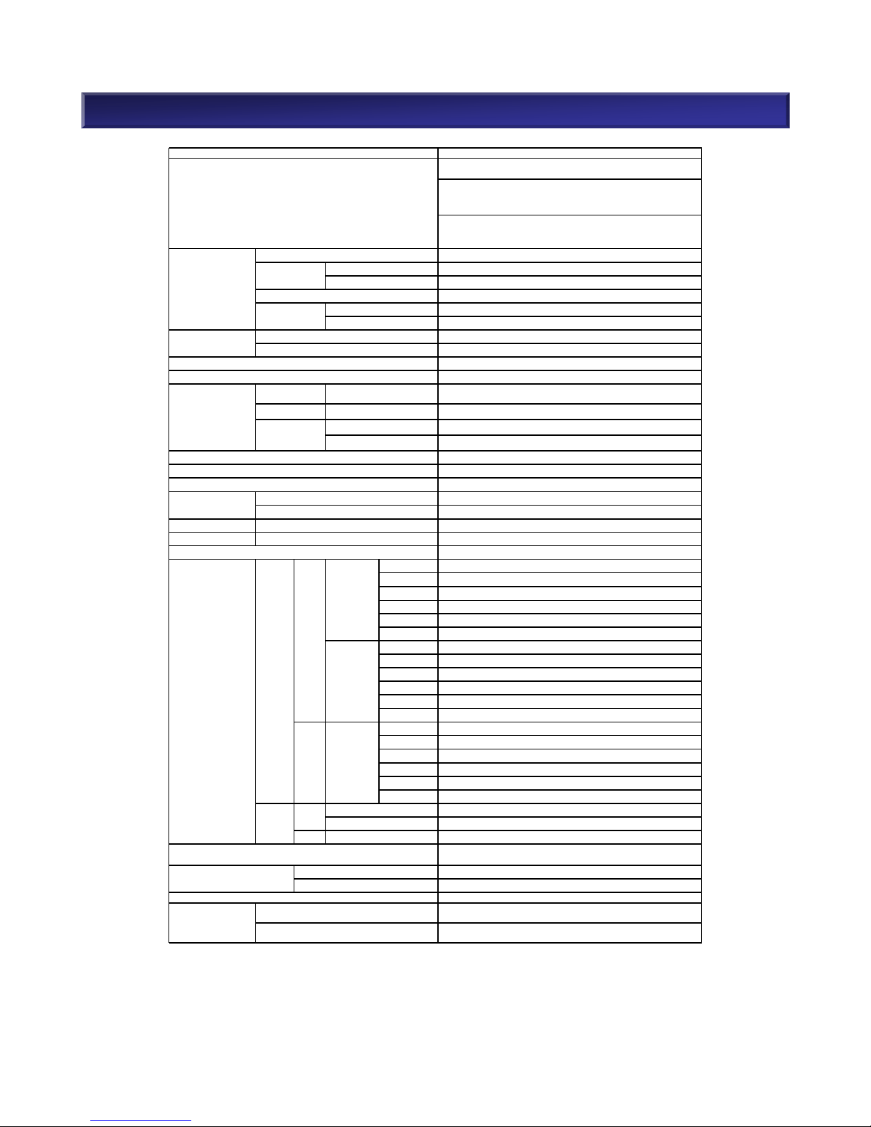
1. Specifications <M110>
3
NEC Confidential
M110
2.5" HDD: Max. 24 HDDs per controller or disk enclosure unit.
3.5" HDD: Max. 12 HDDs per controller or disk enclos ure unit.
Max. 120 HDDs supported.
Up to four disk enc losure units with 2. 5" HDD and/or up to nine disk
enclosur e units w ith 3.5" HDD can be connected to the controller unit.
SAS/NL-SAS/SSD are suppor ted on the sam e controller and disk enc losure
unit. 2.5" and 3.5" m ixed HDD environments are not support ed on the same
controller and disk enclos ure unit.
FC 8/16Gb x 2-8
10Gb x 2-8
1/10Gb x 2/4/8
SAS 12Gb x 4/8
8/16G FC x 2-4 + 10G iSCSI x 2-4
8/16G FC x 2-4 + 1/10G iSCSI x 2/4
Capacity
8
GB(single c ontroller]), 16GB(Dual c ontroller)
Backup tim e Unlimited
1 or 2
12Gbps SAS x 2(dual c ontroller), 12Gbps SAS x 1(si ngle controller)
SAS
300GB(15Krpm ), 600GB(15Krpm), 600GB (10Krpm), 1.2TB(10krpm ),
1.8TB(10krpm )
NL-SAS 2TB(7.2Krpm ), 4TB(7.2Krpm ), 6TB(7.2Krpm)
200GB, 400GB, 1.6TB
200GB, 400GB, 1.6TB
SAS (Max transfer s peed 12Gbps) x 2
120 units
(*3)
12 units
0, 1, 5, 6, TM, 10, 50, 60
1, 10, 5(4+P ), 50(4+P ), 6(4+PQ) /(8+PQ), 60(4+ PQ)(8+PQ)
Dimens ions 482 x 556.0 x 87.4 (2U)
Weight 31kg or less
AC:100 - 240V, DC: 48V
FC 505W
iSCSI(Opt ical) 510W
iSCSI(Copper ) 515W
Combo(O ptical) 510W
Combo(C opper) 510W
SAS 500W
FC 510W
iSCSI(Opt ical) 510W
iSCSI(Copper ) 520W
Combo(O ptical) 510W
Combo(C opper) 515W
SAS 505W
FC 455W
iSCSI(Opt ical) 455W
iSCSI(Copper ) 465W
Combo(O ptical) 455W
Combo(C opper) 460W
SAS 450W
350W
350W
3.5" 295W
Operating: 5 to 40°C, 10 - 80%
Non-Operating: - 10 to +60℃, 5 - 80%
Windows , Linux,
VMware, Hyper-V, KVM
Intel Ivy Bridge
800 W x2 per Base unit.
Hot Swap and R edundancy Support
800 W x2 per Base unit.
Hot Swap and R edundancy Support
*2 Available to Hot swap,driv e failure detection and reb uild
*3 Refer t o P.26 Com ponent Selection(21) [CAUTION:The Number of Disk Enclosur es]
*4 See Suppor t matrix f or detailed information
*1 Support disk encryption f or SAS 2.5" 600GB(15krpm) , SAS 2.5" 600GB(10krpm ), NL-SAS 4TB(7.2krpm),
SSD 2.5" 200GB, and SS D 3.5" 200GB.[Not suppor ted in China]
2.5"
3.5"
2.5"
SAS(15k)
NL SAS(7.2k)
2.5"
SAS(15k)
SAS(10k)
Temperatur e / Humidity c onditions
3.5"
Hypervisor
Supported OS
(*4)
Open OS
Max Power cons umption
(W)
DE
DAC
NL SAS(7.2k)
SAS(10K)
Number of c ontrollers
Power s upply
SSD
with 3.5" HDDs
SSD
SAS, NL-SAS
RAID levels
W x D x H mm
2.5"
3.5"
Optical
Copper
8/16G FC/10G iSCSI(O ptical)
Item
Host interfac e /
Number of hos t ports
Cache
Chassis configuration
8/16G FC/10G iSCSI(Copper )
Intermix
Type of Proc essor
Power supply
(include Fan)
Disk Array C ontroller
Disk Enc losure
Disk D rive
(*1,* 2)
iSCSI (10Gb)
Max. number of SSD
Disk I/F
Disk Enc losure
Max. number of disk dri ves
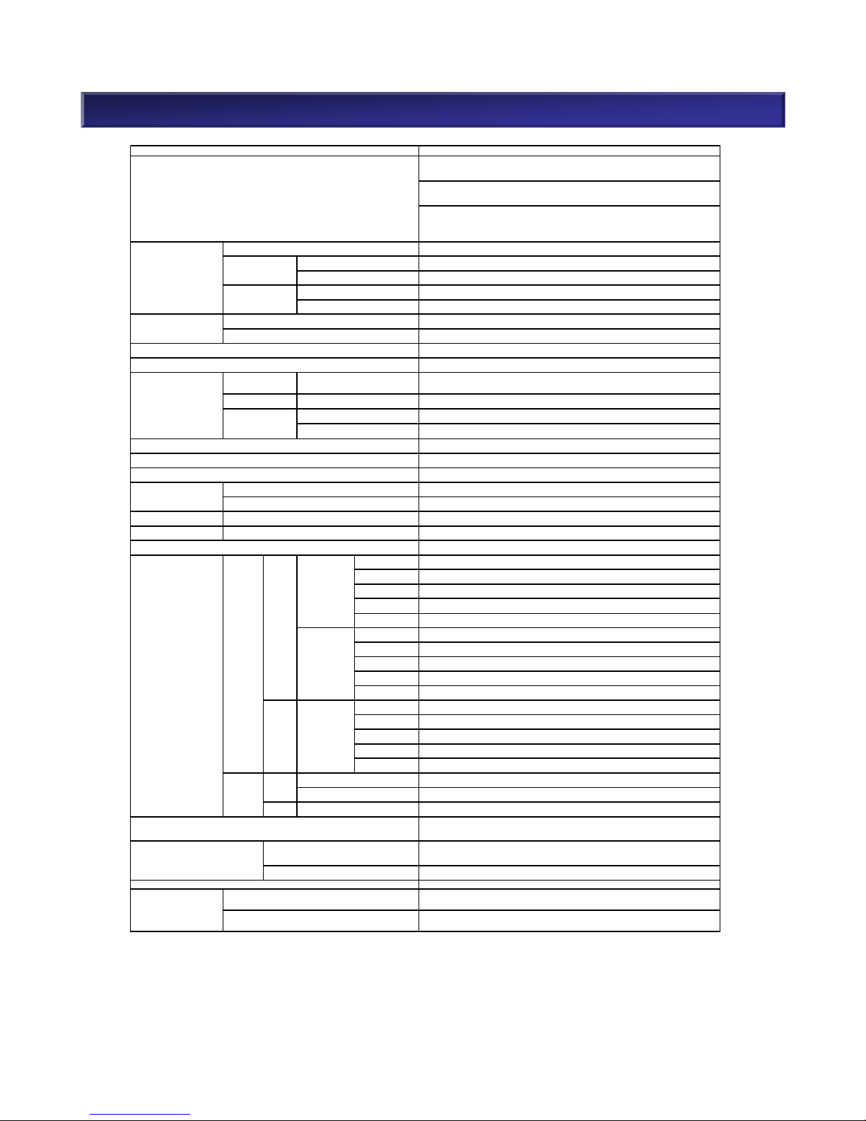
1. Specifications <M310>
4
NEC Confidential
M310
2.5" HDD: Max. 24 HDDs per controller or disk enclos ure unit.
3.5" HDD: Max. 12 HDDs per controller or disk enclos ure unit.
2.5" HDD: Max. 480 HDDs supported.
3.5" HDD: Max. 240 HDDs supported.
SAS/NL-SAS/SSD are supported on the same c ontroller and disk
enclosur e unit. 2.5" and 3.5" mixed HDD environments are not supported
on the sam e controller and dis k enclos ure unit.
8/16Gb x 2-8
10Gb x 2-8
1/10Gb x 8
8/16G FC x 2-4 + 10G iSCSI x 2-4
8/16G FC x 2-4 + 10G iSCSI x 4
24/48GB
Unlimited
2
12Gbps SAS x 2
300GB(15Krpm), 600GB(15Krpm ), 600GB(10Krpm), 1.2TB(10krp m),
1.8TB(10krpm )
2TB(7.2Krpm ), 4TB(7.2Krpm), 6TB(7.2Krpm )
200GB, 400GB, 1.6TB
200GB, 400GB, 1.6TB
SAS (Max transfer speed 12Gbps) x 2
480 units(2.5"), 240 units(3.5")
(*3)
480 units(2.5"), 240 units(3.5")
(*3)
0, 1, 5 ,6, TM, 10, 50, 60
1, 10, 5(4+P), 50(4+P ), 6(4+PQ)/( 8+PQ), 60(4+ PQ)/( 8+PQ)
Dim ensions 482 x 556.0 x 87.4 (2U)
Weight 31kg or less
AC:100 - 240V, DC 48V
FC 550W
iSCSI(Opt ical) 555W
iSCSI(Copper ) 560W
Combo( Optical) 555W
Combo( Copper) 555W
FC 555W
iSCSI(Opt ical) 560W
iSCSI(Copper ) 565W
Combo( Optical) 555W
Combo( Copper) 560W
FC 500W
iSCSI(Opt ical) 500W
iSCSI(Copper ) 510W
Combo( Optical) 500W
Combo( Copper) 505W
350W
350W
3.5" 295W
Operating: 5 to 40℃, 10 - 80%
Non-Operating: -10 to +60℃, 5 - 80%
Window s, Linux, Solaris, HP-UX, AIX
VMWare, Hyper-V, KVM
Intel Ivy Bridge
800 W x4 per Base unit.
Hot Swap and Redundanc y Support
800 W x4 per Base unit.
Hot Swap and Redundanc y Support
*2 Available to Hot swap,drive failure detect ion and rebuild
*3 R efer to P.47 Com ponent Selection(17) [CAUTION:The Number of D isk Enclosures ]
*4 See Support matrix for detailed information
*1 Support dis k encryption for SAS 2.5" 600GB(15krpm), S AS 2.5" 600GB(10krpm), NL-SAS 4TB(7.2krpm),
SSD 2.5" 200GB, and SSD 3.5" 200GB.[Not supported in China]
SAS(10k)
2.5"
3.5"
3.5"
2.5"
SAS(15k)
Disk Array C ontroller
SAS, NL-SAS
SSD
Item
Chassis configuration
Host interface /
Number of host ports
FC
iSCSI (10Gb)
Intermix
8/16G FC/10G iSCS I(Optical)
8/16G FC/10G iSCS I(Copper)
Backup Tim e
Number of co ntrollers
DAC-DE I/F
SSD
NL-SAS
2.5"
Optical
Copper
DE
2.5"
Disk E nclosur e
Max. number of disk drives
DAC
3.5"
Cache
Capacity
NL SAS(7.2k)
Max Power cons umption
(W)
Disk D rive
(*1, *2)
SAS
NL SAS(7.2k)
SAS(15k)
Max. number of SSD
RAID Level
W x D x H mm
Power s upply
(include Fan)
Type of Processor
with 3.5" HDD s
Power Supply
Disk E nclosur e
Temper ature / Humidity conditions
Supported O S
(*3)
Open O S
Hypervisor
SAS(10k)

M110 Component Selection
5
NEC Confidential
2. M110 Component Selection (1)
n Structure
M110 Disk Array is a compact and entry level disk storage system in NEC Storage M-Series.
M110 has the following host interfaces: 8/16Gb FC, 1/10Gb iSCSI, 12Gb SAS, Combo(FC and
iSCSI). M110 base units support 24x 2.5” drives and 12x 3.5” drives per 2U chassis. Disk
enclosures can include a mix of SAS disk drives, Nearline SAS disk drives and SAS SSD.
Disk drives can be added to the maximum 120 disk drives by connecting disk enclosures.
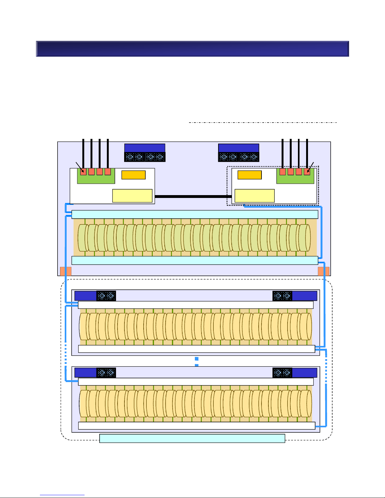
n Overview : M110 Disk Array (2.5”)
6
NEC Confidential
SAS HDD/SAS SSD
SAS HDD/SAS SSD
SAS HDD/SAS SSD
Controller
BBU
Switch
Switch
Base unit
Power
Fan
DE#01
Switch
Switch
DE#04
Switch
Switch
Disk Enclosure
Refer to “The Number of Disk Enclosures”
Controller
Cache 8GB
BBU
Cache 8GB
DE#00(Build-in)
Power
Fan
Power
Disk Enclosure
Power
Fan
Fan
Host Port Card
SFP
SFP
Host Port Card
Fan
PowerSupply
Fan
PowerSupply
DISK Port
DISK Port
2. M110 Component Selection (2)
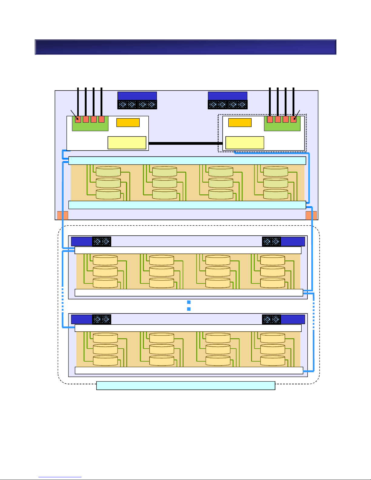
n Overview : M110 Disk Array (3.5”)
7
NEC Confidential
Controller
BBU
Switch
Switch
Base Unit
Power
Fan
電源
DE#01
電源
Switch
Switch
DE#09
Switch
Switch
Disk Enclosure
NL-SAS HDD/SAS SSD
Refer to “The Number of Disk Enclosures”
ControllerCache 8GB
BBU
Cache 8GB
NL-SAS HDD/SAS SSD
NL-SAS HDD/SAS SSD
DE#00(Built-in)
Power
Fan
Power
Disk Enclosure
Power
Fan
Fan
Host Port Card
Fan
PowerSupply
Fan
PowerSupply
SFP
SFP
Host Port Card
DISK Port DISK Port
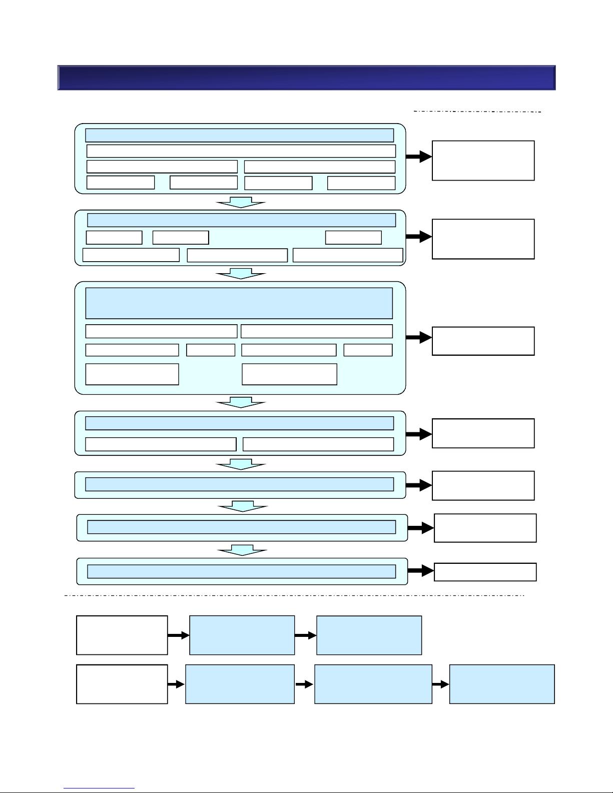
2. M110 Component Selection (3)
n Steps for Component Selection When Purchasing a New System
n Steps for Expansion
(4) Select Disk Enclosure (Number, Type, Power)
2.5” 3.5”
Refer to (2-1) Disk
Array Unit, a) Base
Unit
(1) Select Model of Disk Array Unit (Power/Disk Size)
(3) Select Disk Drive
(Type, Capacity, Number, Function/Hot Spare Disk)
2.5” 3.5”
Select Encryption
Function
SAS SSD NL-SAS SSD
Select Encryption
Function
Refer to (4) Disk
Enclosure
Refer to (2-1) Disk
Array Unit, b) Host
Port Card
Refer to (3-1) Disk
Drive
(2) Host Port Card (Host I/F)
(1)Select Model of
Disk Array Unit
Add Server
/ HBA / NIC/
SAS Controller
Expand Disk
Capacity
(3)Select Disk Drive
(5)Select Dummy HDD
(4)Select Disk Enclosure
(6)Select Front Bezel
(7)Select Rack
(7) Select Rack
(6) Select Front Bezel
Refer to (6) Front
Bezel
Refer to 3. Rack Guide
(5) Select Dummy HDD
Refer to (5) Dummy
HDD
8
NEC Confidential
FC/10Gb iSCSI Combo
8Gb FC 12Gb SAS16Gb FC
1/10Gb iSCSI(Copper)
10Gb iSCSI(Optical)
2.5” 3.5”
Power Supply(AC,DC)
Single Controller
Dual Controller
2.5” 3.5”
(2)Host Port Card

If FC, choose 8/16Gb FC 2/4/8 ports.
If 1Gb iSCSI, choose 1Gb iSCSI Copper 2/4/8 ports.
If 10Gb iSCSI, choose 10Gb iSCSI Copper/Optical 2/4/8 ports.
If 12Gb SAS, choose 12Gb SAS 4/8 ports.
If Combo, choose 8/16Gb FC 2/4 ports and 1/10Gb iSCSI
Copper/Optical 2/4 ports.
Ø Refer to M110 Component Selection (2-1): Product List,
b) Host Port Card
Ø Refer to M110 Component Selection (2-3) Choose Host
I/F
Choose Dual Controller Configuration (Controller card x 2)
Ø Refer to M110 Component Selection (2-4): Dual
Controller vs. Single Controller
Choose M110 Disk Array Unit (2.5” model)
Ø Refer to M110 Component Selection (2-1): Product List,
a) Base Unit
2. M110 Component Selection (4)
(1) System Requirement and Recommended Product
Choose Single Controller Configuration (Controller Card x
1)
Ø Refer to M110 Component Selection (2-4): Dual
Controller vs. Single Controller
YES
NO
(3) High reliability and
availability are required.
YES
(2) Space-saving is
required.
(1) Host I/F is determined.
(4) Low cost is required.
YES
YES
An M110 Disk Array Unit does not include disk drives. A controller unit is not included with a base unit.
Both the array controller unit and a controller card are required. The following steps and lists are
references for choosing an appropriate product combination.
9
NEC Confidential
2. M110 Component Selection (5)
Model Number Product Name Remarks Accessories
*1
NF5322-SR01E
M110 Disk Array Unit
(2.5“)
• Power supply unit
AC 100-240V
• 24 x 2.5” disk drives
• NEC Storage Rack Mount Kit
• List of accessories
• Ear Bezels *2(left and right)
• HW Document CD (User Guide,
Setup Guide, Installation Guide)
• NEC Storage PathManager CD
(Windows, Linux)
NF5322-SR00E
M110 Disk Array Unit
(3.5”)
• Power supply unit
AC 100-240V
• 12 x 3.5” disk drives
NF5322SR01DE
M110 Disk Array Unit
(2.5“) (DC 48V)
• Power supply unit
DC 48V
• 24 x 2.5” disk drives
• NEC Storage Rack Mount Kit
• List of accessories
• Ear Bezels *2(left and right)
• HW Document CD (User Guide,
Setup Guide, Installation Guide)
• NEC Storage PathManager CD
(Windows, Linux)
• DC Cables
NF5322SR00DE
M110 Disk Array Unit
(3.5”) (DC 48V)
• Power supply unit
DC 48V
• 12 x 3.5” disk drives
(2) Disk Array Unit
(2-1) Base Unit
10
NEC Confidential
a) Dual controller
Model Number Product Name Remarks Accessories
*1
NF5322SR01SE
M110 Disk Array Unit
(2.5“) Single
Controller model
• Power supply unit
AC 100-240V
• 24 x 2.5” disk drives
• NEC Storage Rack Mount Kit
• List of accessories
• Ear Bezels *2(left and right)
• HW Document CD (User Guide,
Setup Guide, Installation Guide)
• NEC Storage PathManager CD
(Windows, Linux)
NF5322SR00SE
M110 Disk Array Unit
(3.5”) Single
Controller model
• Power supply unit
AC 100-240V
• 12 x 3.5” disk drives
b) Single Controller
*3
Model Number Product Name Remarks Accessories
*1
NF5322-SP00E
M110 option
Controller
For M110 single
Controller model
• List of accessories
c) Option Controller for Single Controller model
*1No front bezel is attached in M-Series Disk Array Units. If necessary, purchase it separately.
*2Ear bezels indicate the black cover panels at both ends of base unit.
*3No support on snapshot, data replication and cluster functions in Single Controller Configuration.
Refer to (2-4) Dual Controller vs. Single Controller for more details.
Ear bezel Ear bezel
NEC Confidential
11
2. M110 Component Selection (6)
Model
Number
Product Name Remarks Accessories
NF5322-
SF05E
Host Port Card
(FC 2Ports)
Host Port card x 1(SFP module-less)
- Blank slot x2 for FC SFP
List of
accessories
NF5322-
SF06E
Host Port Card
(FC 4Ports)
Host Port card x 1(SFP module-less)
- Blank slot x4 for FC SFP
List of
accessories
NF5322-
SF21E
Host Port Card
(10Gb iSCSI optical 2Ports)
Host Port card x 1(SFP module-less)
- Blank slot x2 for 10Gb iSCSI optical SFP
List of
accessories
NF5322-
SF22E
Host Port Card
(10Gb iSCSI optical 4Ports)
Host Port card x 1(SFP module-less)
- Blank slot x4 for 10Gb iSCSI optical SFP
List of
accessories
NF5322-
SF23E
Host Port Card
(10Gb iSCSI Copper 2Ports)
Host Port card x 1
- 1/10Gb iSCSI Copper 2port
List of
accessories
NF5322-
SF24E
Host Port Card
(10Gb iSCSI Copper 4Ports)
Host Port card x 1
- 1/10Gb iSCSI Copper 4port
List of
accessories
NF5322-
SF44E
Host Port Card
(12Gb SAS 4Ports)
Host Port card x 1
- 12Gb SAS 4port
List of
accessories
NF5322-
SF83E
Host Port Card
(FC/10Gb iSCSI Optical Combo)
Host Port card x 1
- Blank slot x2 for FC SFP
- Blank slot x2 for 10Gb iSCSI optical SFP
List of
accessories
NF5322-
SF84E
Host Port Card
(FC/10Gb iSCSI Copper Combo)
Host Port card x 1
- Blank slot x2 for FC SFP
- Blank slot x2 for 1/10Gb iSCSI copper
List of
accessories
2-2) Host Port Card
NEC Confidential
12
2. M110 Component Selection (7)
(2-3) SFP Module for FC, iSCSI(Optical), and Combo
In case of SFP module-less host port card, it is required to purchase appropriate SFP module.
Refer to the following table and available SFP module combination on next page for appropriate
SFP type and quantity.
Model Number Product Name Remark
NF5322-SFP08E SFP Module(8Gb FC) SFP module 8Gb FC x2
NF5322-SFP16E SFP Module(16Gb FC) SFP module 16Gb FC x2
NF5322-SFP10E SFP Module(10Gb iSCSI Optical) SFP module 10Gb iSCSI Optical x2
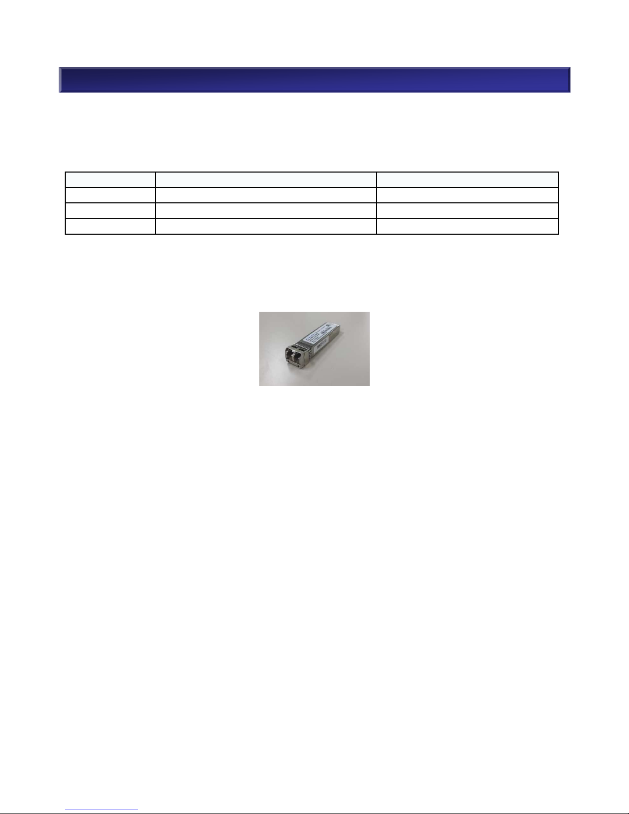
■SFP(Small Form factor Pluggable) module
SFP module is kind of the transceiver to communicate in a Fibre channel or Gigabit Ethernet. The
connection of the apparatus is enabled by putting it on Host Port Card. Therefore, the arrangement of
the SFP module becomes required.
Port
combination
per unit
8Gb FC SFP
[NF5322-SFP08E]
16G FC SFP
[NF5322-SFP16E]
8G FC 2Port 1 0
8G FC 4Port 2 0
8G FC 6Port 3 0
8G FC 8Port 4 0
16G FC 2Port 0 1
16G FC 4Port 0 2
16G FC 6Port 0 3
16G FC 8Port 0 4
8G FC 2Port
16G FC 2Port
1 1
8G FC 2Port
16G FC 4Port
1 2
8G FC 2Port
16G FC 6Port
1 3
8G FC 4Port
16G FC 2Port
2 1
8G FC 4Port
16G FC 4Port
2 2
8G FC 6Port
16G FC 2Port
3 1
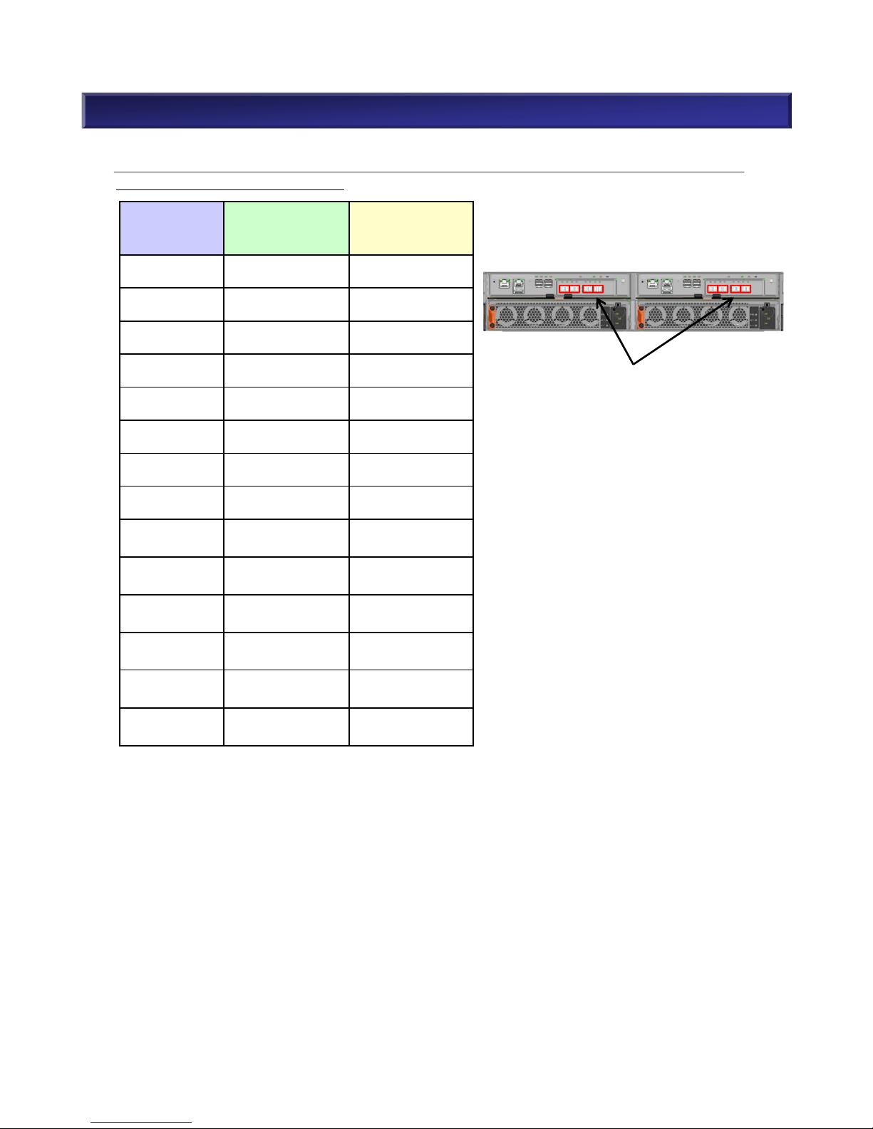
■Available SFP Module combination for Host Port Card (FC 4Port) [NF5322-SF06E]
The following table shows available SFP combination in case of M110 disk array(dual controller)
with two Host Port Card(FC 4Port).
Max 8 SFPs (corresponded to 4-Model
Number) per unit are available.
2. M110 Component Selection (8)
NEC Confidential
13
M110 M110
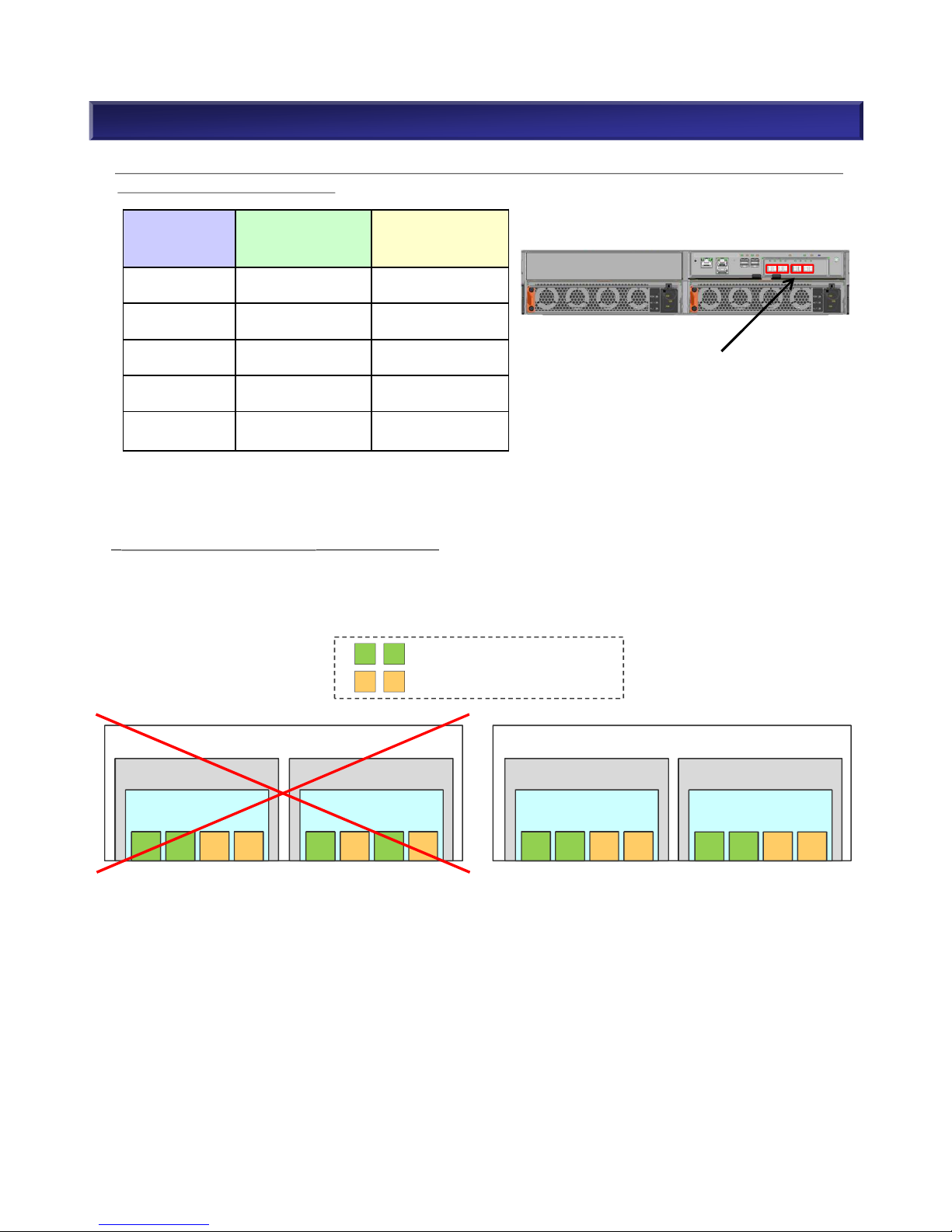
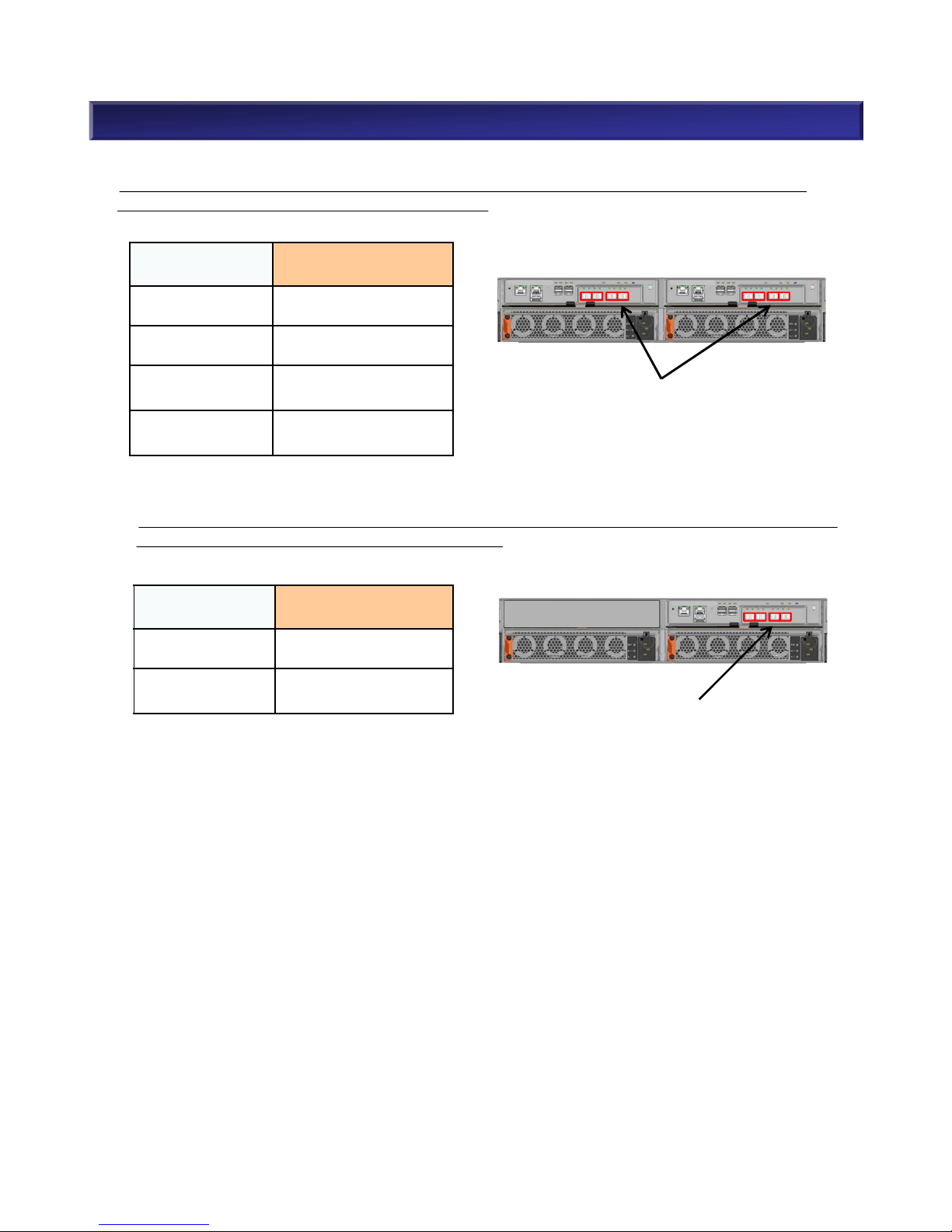
* Caution for installation of FC SFP module
Mixed installation with 8Gb FC SFP and 16Gb FC SFP is available. However, you need to install each
SFP at the same position when you set up dual controller configuration.
Controller 1
Host Port Card
Port0 Port1 Port2 Port3
・・・SFP module (8Gb FC)
・・・SFP module 16Gb FC)
Controller 1
Host Port Card
Port0 Port1 Port2 Port3
Controller 0
Host Port Card
Port0 Port1 Port2 Port3
Controller 0
Host Port Card
Port0 Port1 Port2 Port3
2. M110 Component Selection (9)
NEC Confidential
14
NG
Good
Port
combination
per unit
8Gb FC SFP
[NF5322-SFP08E]
16G FC SFP
[NF5322-SFP16E]
8G FC 2Port 1 0
8G FC 4Port 2 0
16G FC 2Port 0 1
16G FC 4Port 0 2
8G FC 2Port
16G FC 2Port
1 1
The following table shows available SFP combination in case of M110 disk array(single controller) with
one Host Port Card(FC 4Port).
Max 4 SFPs (corresponded to 2-model
Number) per unit are available.
■Available SFP Module combination for Host Port Card(10Gb iSCSI Optical 4Port) [NF5322-SF22E]
The following table shows available SFP combination in case of M110 disk array(dual controller)
with two Host Port Card(10Gb iSCSI Optical 4Port).
Port combination
per unit
10Gb iSCSI Optical SFP
[NF5322-SFP10E]
10G iSCSI Optical
2Port
1
10G iSCSI Optical
4Port
2
10G iSCSI Optical
6Port
3
10G iSCSI Optical
8Port
4
The following table shows available SFP combination in case of M110 disk array(single controller)
with two Host Port Card(10Gb iSCSI Optical 4Port).
Port combination
per unit
10Gb iSCSI Optical SFP
[NF5322-SFP10E]
10G iSCSI Optical
2Port
1
10G iSCSI Optical
4Port
2
2. M110 Component Selection (10)
Max 8 SFPs (corresponded to 4-Model
Number) per unit are available.
Max 4 SFPs (corresponded to 2-Model
Number) per unit are available.
NEC Confidential
15
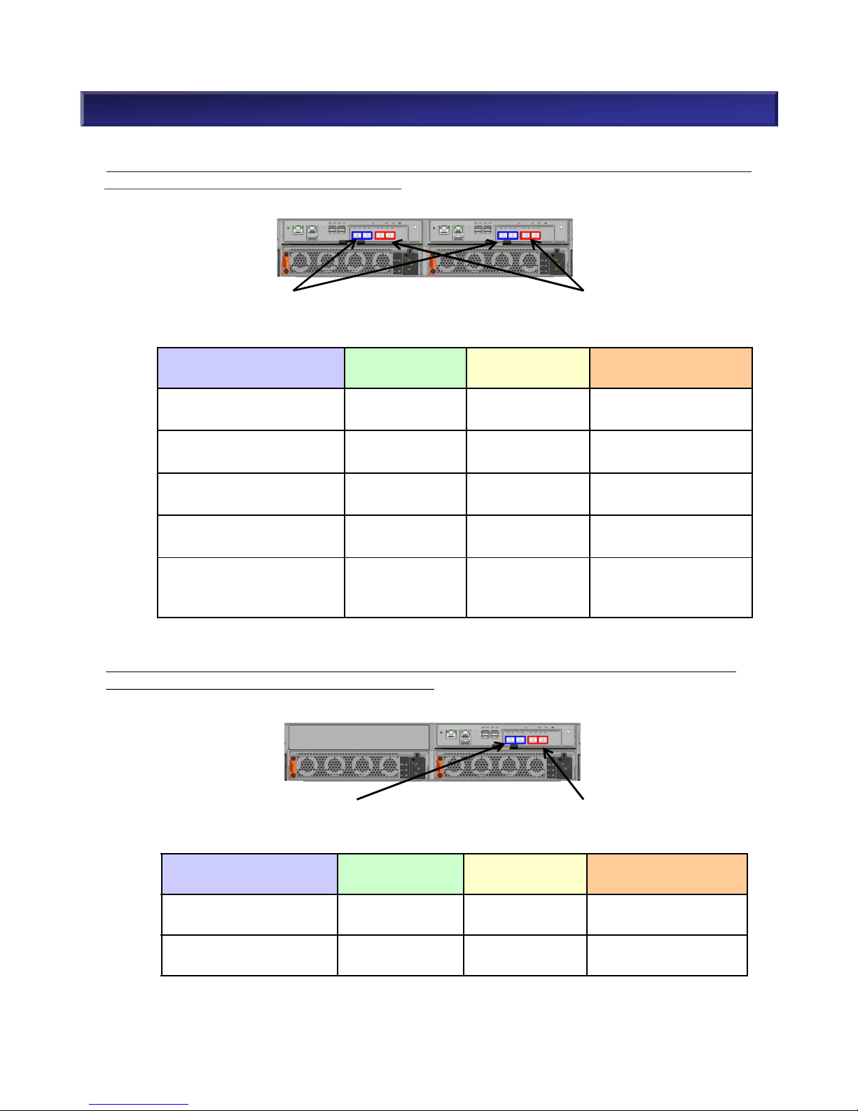
■ Available SFP Module combination for Host Port Card(FC/10Gb iSCSI Optical) [NF5322-SF83E]
The following table shows available SFP combination in case of M110 disk array(dual controller) with
two Host Port Card(FC / 10Gb iSCSI Optical).
Port combination
per unit
8Gb FC SFP
[NF5322-SFP08E]
16G FC SFP
[NF5322-SFP16E]
10Gb iSCSI Optical SFP
[NF5322-SFP10E]
8G FC 2Port
10G iSCSI Optical 2Port
1 0 1
16G FC 2Port
10G iSCSI Optical 2Port
0 1 1
Port combination
per unit
8Gb FC SFP
[NF5322-SFP08E]
16G FC SFP
[NF5322-SFP16E]
10Gb iSCSI Optical SFP
[NF5322-SFP10E]
8G FC 2Port
10G iSCSI Optical 2/4Port
1 0 1 or 2
8G FC 4Port
10G iSCSI Optical 2/4Port
2 0 1 or 2
16G FC 2Port
10G iSCSI Optical 2/4Port
0 1 1 or 2
16G FC 4Port
10G iSCSI Optical 2/4Port
0 2 1 or 2
8G FC 2Port
16G FC 2Port
10G iSCSI Optical 2/4Port
1 1 1 or 2
The following table shows available SFP combination in case of M110 disk array(single controller)
with one Host Port Card(FC / 10Gb iSCSI Optical).
2. M110 Component Selection (11)
Max 4 iSCSI SFPs (corresponded to
2-Model Number) per unit are available.
Max 4 FC SFPs (corresponded to 2Model Number) per unit are available.
Max 2 iSCSI SFPs (corresponded to 1Model Number) per unit are available.
Max 2 FC SFPs (corresponded to 1Model Number) per unit are available.
NEC Confidential
16
■ Available SFP Module combination for Host Port Card(FC/10Gb iSCSI Copper) [NF5322-SF84E]
Host Port Card(FC/10Gb iSCSI Copper) initially has 2port of 10Gb iSCSI Copper.
The following table shows available SFP combination in case of M110 disk array(dual controller) with
two Host Port Card(FC / 10Gb iSCSI Copper).
Port combination
per unit
8Gb FC SFP
[NF5322-
SFP08E]
16G FC SFP
[NF5322-
SFP16E]
8G FC 2Port
10Gb iSCSI Copper 2Port
1 0
16G FC 2Port
10Gb iSCSI Copper 2Port
0 1
Port combination
per unit
8Gb FC SFP
[NF5322-
SFP08E]
16G FC SFP
[NF5322-
SFP16E]
8G FC 2Port
10Gb iSCSI Copper 4Port
1 0
8G FC 4Port
10Gb iSCSI Copper 4Port
2 0
16G FC 2Port
10Gb iSCSI Copper 4Port
0 1
16G FC 4Port
10Gb iSCSI Copper 4Port
0 2
8G FC 2Port
16G FC 2Port
10Gb iSCSI Copper 4Port
1 1
The following table shows available SFP combination in case of M110 disk array(single controller)
with one Host Port Card(FC / 10Gb iSCSI Copper).
Unit with two FC/10Gb iSCSI Copper Host
Port Card, has initially four 10 Gb iSCSI
Copper ports.
2. M110 Component Selection (12)
Max 4 FC SFPs (corresponded to
2-Model Number) per unit are
available.
Unit with one FC/10Gb iSCSI Copper Host
Port Card, has initially two 10 Gb iSCSI
Copper ports.
Max 2 FC SFPs (corresponded to 1Module Number) per unit are available.
NEC Confidential
17
2. M110 Component Selection (13)
(2-4) Choose Host I/F
Notes: Single Controller Configuration
1) There is a case where the system crashes when a controller fails and although it is extremely
rare, data integrity cannot be guaranteed. To maintain higher reliability, a dual controller
configuration (standard model) is recommended.
2) Since write-cache is off, the write process does not use cache.
• 8/16Gb FC: High speed interface
• 10Gb iSCSI(Optical): High speed and easy connection interface
• 1/10Gb iSCSI(Copper): Low cost and easy connection interface
• 12Gb SAS: Low cost DAS(Direct Attached Storage) interface
• 16Gb FC and 10Gb iSCSI : Combo
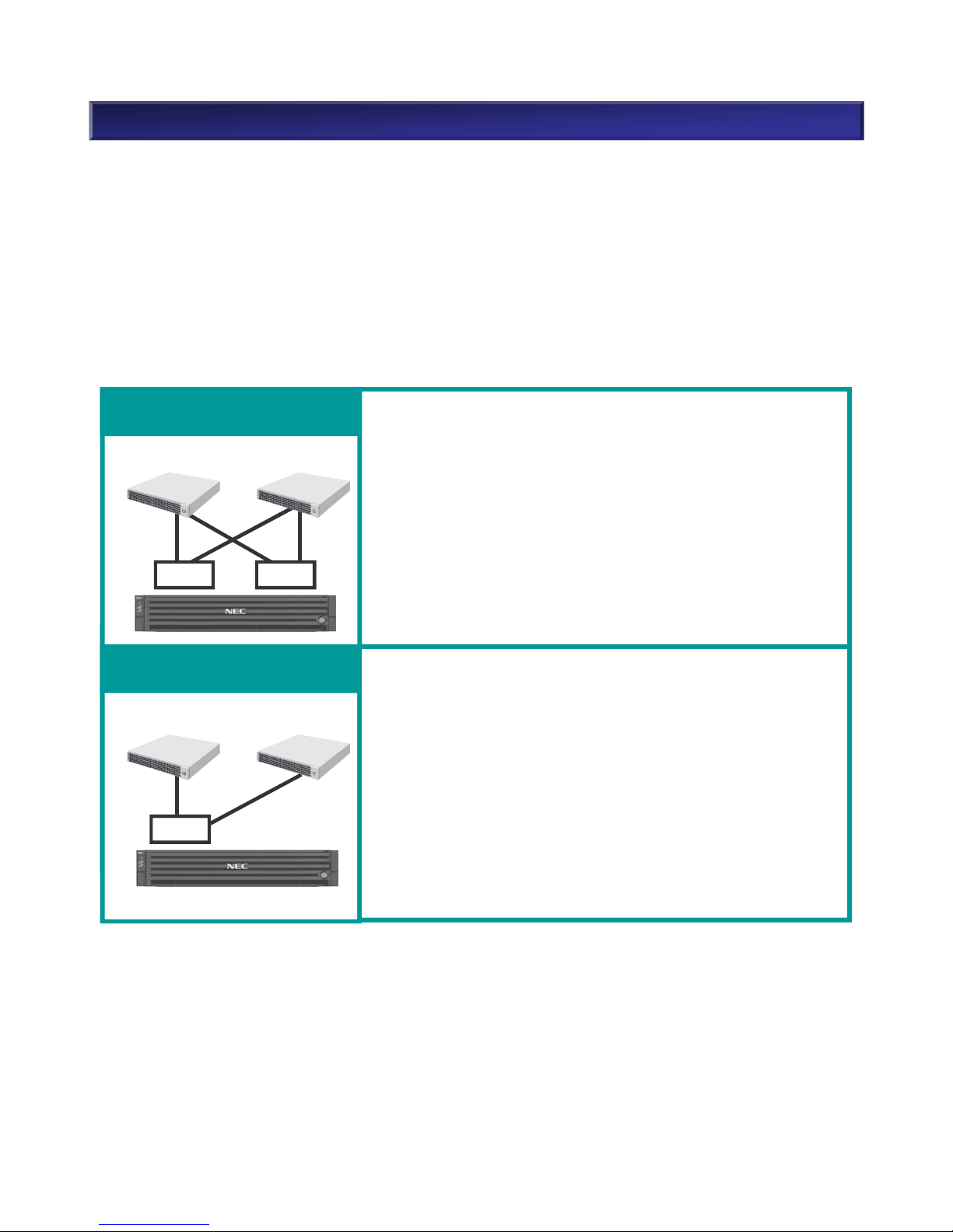
(2-5) Dual Controller vs. Single Controller
18
NEC Confidential
u Characteristics
• Pros
High Functionality/High Availability
Data Protection
Online Firmware update
Snapshot, In-box/Inter-box Replication
• Cons
Higher cost than single controller configuration
u Usage
Dual controller storage for requiring 24 hours x 7 days operation
(e.g.) System that provides services to users such as database
and groupware operation, etc.
Dual Controller Configuration
(Standard Model)
Single Controller Configuration
(Low Cost Model)
uCharacteristics
• Pros
Lower cost than dual controller configuration
• Cons
No support on cluster/FT server
No snapshot/data replication
No online Firmware upgrade
◆ Usage
Single Controller storage for back up data as the primary back up
(e.g.) System which has a backup server connected with a
storage unit (single controller) as the primary backup and
a tape drive as the secondary backup.
cont. cont.
cont.
2. M110 Component Selection (14)
(2-6) NEC StorageManager Suite
NEC StorageManager Express is embedded in storage M110. This software can manage an M110
with basic functionalities and no management server is necessary. W hen more functions are required
such as data replication, purchase NEC StorageManager Suite that requires a management server.
Refer to the table below for functions which are available with NEC StorageManager Suite.
*1FC and iSCSI host I/F are supported. SAS host I/F is not supported.
NEC StorageManager Suite specific functions
[] designates optional product packages which can be purchased with
NEC StorageManager Suite.
Supported Storage
M110
Monitor multiple storages
○
Linkage with ESMPRO
○
Linkage with SigmaSystemCenter
○
Event Link (Report by e-mail. Run executable)
○
Monitor performance [NEC Storage PerformanceMonitor]
○
Analyze performance [NEC Storage PerformanceNavigator]
○
Alert (Express Alert, cooperate with syslog)
○
In-box replication [NEC Storage DynamicDataReplication]
○
Inter-box replication [NEC Storage RemoteDataReplication]
○
*1
Prevent unauthorized access or modification of data [NEC
Storage VolumeProtect]
○
19
NEC Confidential
○:Supported -:Not supported
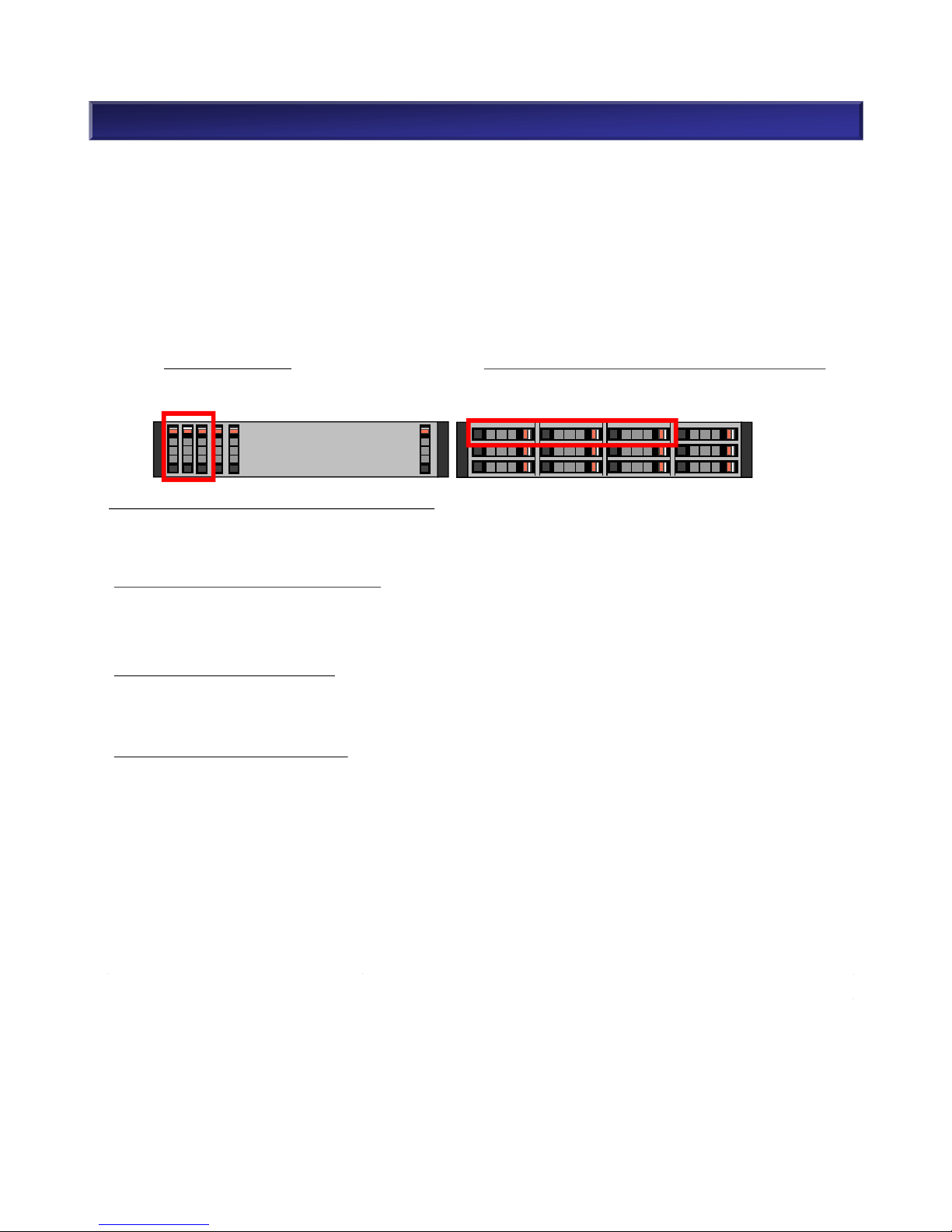
2. M110 Component Selection (15)
Slots #00, #01, and #02 must be populated.
(3) Disk Drive
(3-1) Disk Drive
When deciding how many disk drives are required, remember that logical disk capacity varies
depending on disk drive type (I/F, capacity) and RAID type. The number of disk drives is dependent on
the amount of logical disk capacity that is required. The amount of required logical disk capacity varies
depending on the amount of data usage and whether or not features (Snapshot, Replication) are
required. Using required logical disk capacity and performance that is required, decide the number of
disk drives, taking into account the disk drive type (I/F, capacity, rotation speed) and RAID type.
At least three disk drives have to be populated with any disk drive types (SAS/NL-SAS/SAS SSD)
Refer to “(5) Supported RAID” for supported RAID types.
(3-2) Disk Capacity
(Considerations for System Volume)
A system volume, in which performance logs, etc. are automatically saved, is created in the first
binding Pool. System volume capacity is 8.0 GB. (or 8.6GB if 1KB = 1000Byte)
(Considerations for Snapshot)
When using the snapshot feature, it is necessary to create a snapshot reservation area for replication
of a master volume (snapshot).
(Considerations for Replication)
When implementing the replication feature, use the storage system information retention function* and
create a replication reserved volume with the NEC StorageManager application. The capacity of a
replication reserved volume is 8.0GB. (or 8.6GB if 1KB = 1000Byte)
When turning power off via a planned shutdown all storage system information (differential map, etc)
will be backed up onto the replication reserved volume only if it was configured. If the replication
reserved volume is not configured then storage system information will be lost on shutdown. When
restarting after a planned shutdown, I/O load will be generated as data on the MV is fully copied to the
RV. This startup load may be large enough to temporarily affect performance. It is recommended to
operate 24 hours nonstop, especially if running without a replication reserved volume.
* Storage system information retention function is used to backup storage system information such as
the differential map between business volume (MV) and replication volume (RV) onto disk drives.
20
NEC Confidential
#00 #01 #02 #03
#04 #05 #06 #07
#08 #09 #0A #0B
#17
・・・
#00
#01
#02
#03

NEC Confidential 21
Considerations for Lifetime of Disk Drive
・Lifetime of SAS HDD, Nearline SAS HDD and SAS SSD are 5 years.
2. M110 Component Selection (16)

(3-3) Disk Drive Type
Select a disk drive type from the following table and decide how many drives are needed.
2. M110 Component Selection (17)
22
NEC Confidential
Model Number Product Name
NF5322-SMA75E SAS Disk Drive(2.5" 15krpm/300GB )
NF5322-SMA78E SAS Disk Drive(2.5" 15krpm/600GB )
NF5322-SMA78LE
*1
SAS Disk Drive(2.5" 15krpm/600GB Self-encrypting)
NF5322-SM768E SAS Disk Drive(2.5" 10krpm/600GB )
NF5322-SM768LE
*1
SAS Disk Drive(2.5" 10krpm/600GB Self-encrypting)
NF5322-SM76AE SAS Disk Drive(2.5" 10krpm/1.2TB )
NF5322-SMB6CE
*3
SAS Disk Drive(2.5" 10krpm/1.8TB)
NF5322-SSAG5E
*2
SAS SSD (2.5" 200GB)
NF5322-SSAG5LE
*1 *2 *3
SAS SSD(2.5" 200GB Self-encrypting)
NF5322-SSA96E
*2
SAS SSD (2.5” 400GB)
NF5322-SSA9AE
*2
SAS SSD (2.5” 1.6TB)
NF5322-SMA75GE SAS Disk Drive(2.5" 15krpm/300GB ) x 10 pcs
NF5322-SMA78GE SAS Disk Drive(2.5" 15krpm/600GB ) x 10 pcs
NF5322-SMA78LGE
*1
SAS Disk Drive(2.5" 15krpm/600GB Self-encrypting) x 10pcs
NF5322-SM768GE SAS Disk Drive(2.5" 10krpm/600GB ) x 10 pcs
NF5322-SM768LGE
*1
SAS Disk Drive(2.5" 10krpm/600GB Self-encrypting) x 10 pcs
NF5322-SM76AGE SAS Disk Drive(2.5" 10krpm/1.2TB) x 10 pcs
NF5322-SMB6CGE
*3
SAS Disk Drive(2.5" 10krpm/1.8TB) x 10 pcs
NF5322-SSAG5GE
*2
SAS SSD (2.5" 200GB) x 10 pcs
NF5322-SSAG5LGE
*1 *2 *3
SAS SSD(2.5" 200GB Self-encrypting) x 10 pcs
NF5322-SSA96GE
*2
SAS SSD (2.5” 400GB) x 10 pcs
NF5322-SSA9AGE
*2
SAS SSD (2.5” 1.6TB) x 10 pcs
NF5322-SM708E NL-SAS Disk Drive(3.5" 7.2krpm/2TB)
NF5322-SM70AE NL-SAS Disk Drive(3.5" 7.2krpm/4TB)
NF5322-SM70ALE
*1
NL-SAS Disk Drive(3.5" 7.2krpm/4TB Self-encrypting)
NF5322-SMB0CE
*3
NL-SAS Disk Drive(3.5" 7.2krpm/6TB)
NF5322-SSAR5E
*2
SAS SSD (3.5" 200GB )
NF5322-SSAR5LE
*1 *2 *3
SAS SSD(3.5" 200GB Self-encrypting)
NF5322-SSAF6E
*2
SAS SSD (3.5" 400GB )
NF5322-SSAFAE
*2
SAS SSD (3.5" 1.6TB)
NF5322-SM708GE NL-SAS Disk Drive(3.5" 7.2krpm/2TB) x 10 pcs
NF5322-SM70AGE NL-SAS Disk Drive(3.5" 7.2krpm/4TB) x 10 pcs
NF5322-SM70ALGE
*1
NL-SAS Disk Drive(3.5" 7.2krpm/4TB Self- encrypting) x 10 pcs
NF5322-SMB0CGE
*3
NL-SAS Disk Drive(3.5" 7.2krpm/6TB) x 10 pcs
NF5322-SSAR5GE
*2
SAS SSD (3.5" 200GB) x 10 pcs
NF5322-SSAR5LGE
*1 *2 *3
SAS SSD(3.5" 200GB Self-encrypting) x 10 pcs
NF5322-SSAF6GE
*2
SAS SSD (3.5" 400GB) x 10 pcs
NF5322-SSAFAGE
*2
SAS SSD (3.5" 1.6TB) x 10 pcs
*1 Encrypted HDDs are not supported in China
*2 In general, lead time of SSD is longer than lead time of HDD. When you order the SSD,
please consider two to three months lead time to get the SSD.
*3 Storage Control Software Revision 0920 or above, and NEC StorageManager Ver9.2 or
above are required.
2. M110 Component Selection (18)
(3-5) Supported RAID
NEC Storage M-Series supports the following RAID types. (Note: Only RAID-1, 10, 5/50(4+P),
6/60(4+PQ), 6/60(8+PQ) are supported with SSD)
(3-6) Dynamic Pool
NEC Storage M-Series supports only dynamic pools. LUN capacity can be modified dynamically.
Capacity is constant regardless of the number of disk drives. It is slightly less than the table above.
Striping is automatic when an applicable number of disk drives are used with RAID types that support it.
<Example> RAID-1 with 4 disk drives is automatically configured as RAID-10.
Refer to “5. Functions <Pool>” for more details about dynamic pool.
* RAID-0: Data is not protected.
RAID Type Configuration Number of physical disk drives Redundancy RAID Capacity
RAID-0 * None Physical disk capacity x 1
RAID-1/10 (1+1) x n 2 or more disk drives 1 Physical disk capacity x 1/2
RAID-5/50 (2+P) x n 3 or more disk drives 1 Physical disk capacity x 2/3
(4+P) x n 5 or more disk drives 1 Physical disk capacity x 4/5
(8+P) x n 9 or more disk drives 1 Physical disk capacity x 8/9
RAID-6/60 (4+PQ) x n 6 or more disk drives 2 Physical disk capacity x 2/3
(8+PQ) x n 10 or more disk drives 2 Physical disk capacity x 4/5
RAID-TM (1+1+1) x n 3 or more disk drives 2 Physical disk capacity x 1/3
(3-4) Disk Drive Usage
Both the base unit and SAS disk enclosures can include a mix of SAS disk drives/NL-SAS disk
drives/SAS SSD and disk drives with different capacities and rotation speeds.
A pool must contain disk drives with the same interface. The capacity or rotation speed does not matter.
However, it is strongly recommended to use devices of the same capacity and same rotation speed in
a pool. When using different capacities of disk drive in a pool, the pool will be created based on the
disk drive with the smallest capacity. In this case, the rest of larger disk drives are not available.
Since SAS and Nearline SAS are regarded as different interfaces, it is impossible to mix SAS and
Nearline SAS in same pool. Also mix of HDD and SSD, mix of self-encrypting HDD and non-encrypting
HDD is not available in same pool. For SSD, It is recommended to mix same SSD type and same
capacity.
<Example>
A pool configured by SAS disk drives (15krpm/300GB) and SAS disk drives (15krpm/600GB)
ØThe SAS disk drive (15krpm/600GB) is treated as a SAS disk drive (15krpm/300GB).
When using different speeds of disk drives in a pool, the pool will be created based on the slowest disk
speed. In this case, performance will not be as good as expected because drives with faster speed are
treated the same as drives with the slowest speed.
<Example>
A pool configured by 2.5” SAS disk drives (15krpm/600GB) and 2.5” SAS disk drive(10krpm/600GB)
ØThe SAS disk drive (15krpm/600GB) is treated as a SAS disk drive (10krpm/600GB).
23
NEC Confidential

2. M110 Component Selection (19)
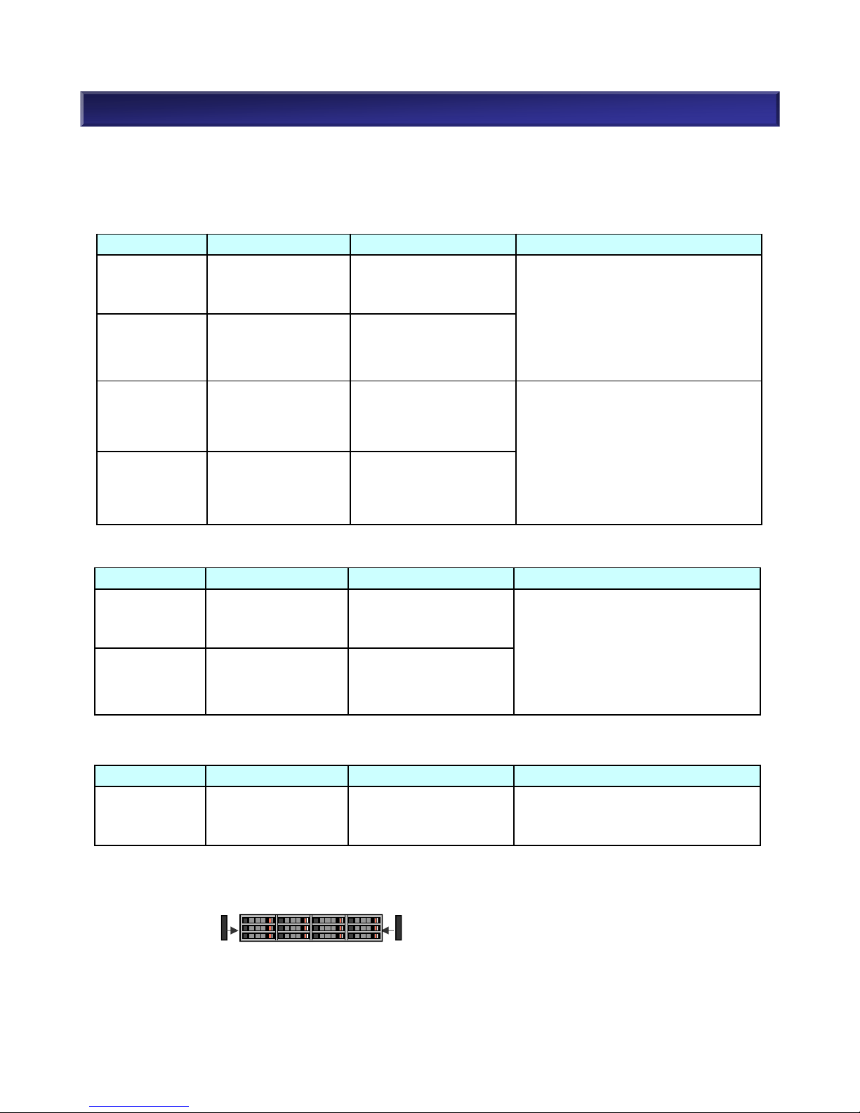
(3-7) Hot Spare Disk
When assigning hot spare disks:
• Assigning a hot spare disk enables automatic restoration of data without waiting for a maintenance
service agent in the event of disk failure. Data redundancy is recovered when restoring the data to
the hot spare.
• M-Series has a ”Preventive maintenance function” that moves data to hot spare disks before a disk
failure occurs by detecting symptoms of the failure in order to maintain redundancy.
• It is strongly recommended to assign a hot spare disk in order to enhance the availability of disk array
units.
• M-Series has a global hot spare function which enables hot spare disks to be used with any
HDD/SSD.
• SSD hot spare is only good with SSDs. SSD cannot be used as a hot spare with HDDs. Likewise,
HDD cannot be used as a hot spare with SSDs.
• When multiple types of disk drives are defined as hot spare disks, the priority is as follows.
1.The same interface, the same capacity and the same rotation speed as the base disk drive*.
2.The same interface, the same capacity as the base disk drive* but the slower disk used first
when multiple speeds of hot spare drives exist.
3.The same interface as the base disk drive*, but larger than the base disk drive*. When multiple
sizes of hot spare disks exist, the smaller disk is used first.
* Base disk drive = disk drive with the smallest capacity/slowest rotation speed in the pool.
• The number of recommended hot spares varies depending on the disk drive type. Refer to the table
below.
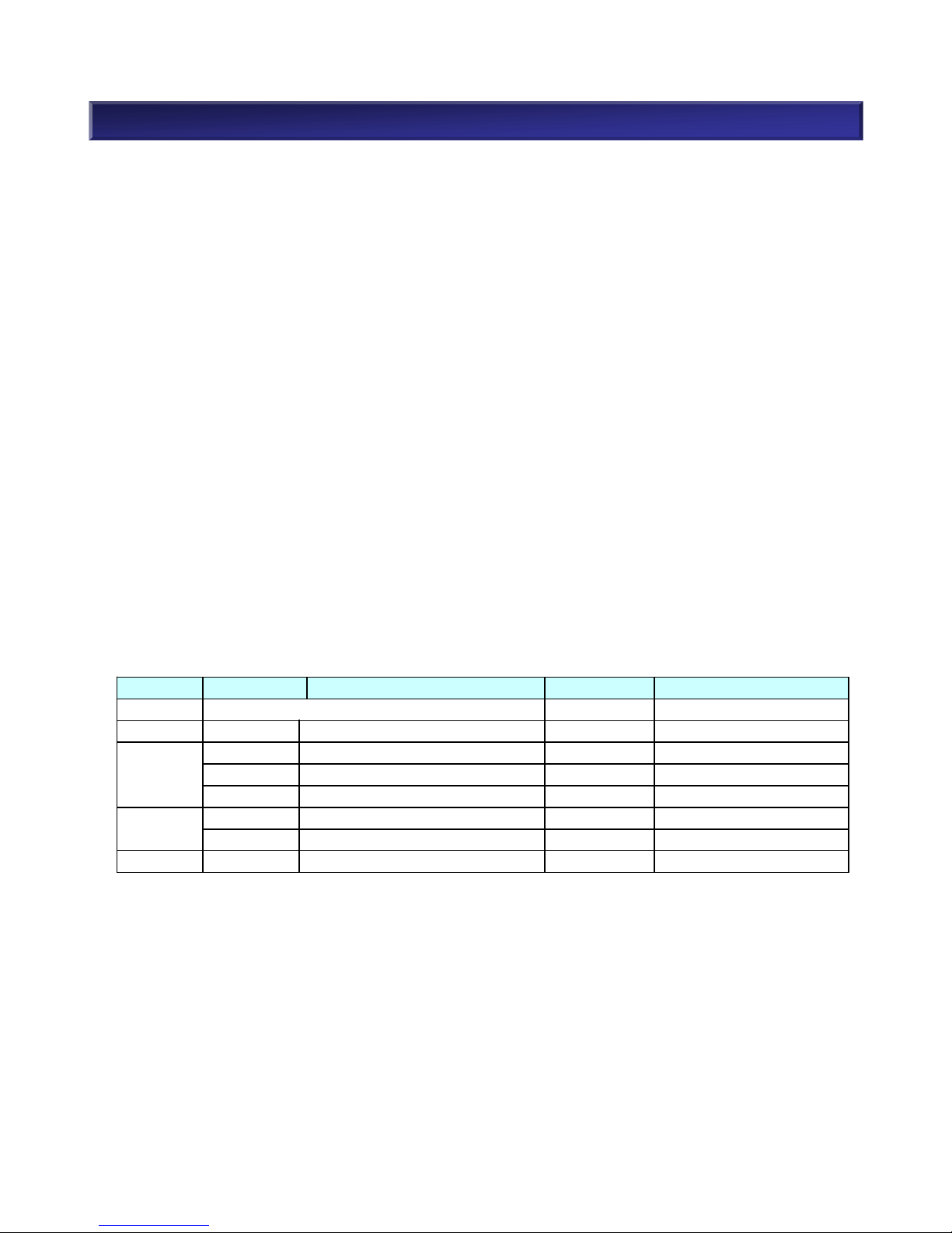
Disk drive type Condition Recommendation
SAS Disk Drive
One type of capacity/rotation speed One hot spare drive / 24 disk drives
n types of capacity/rotation speed n spare disk drives / 24 disk drives
NL-SAS Disk Drive
*1
One type of capacity/rotation speed One hot spare drive / 12 disk drives
n types of capacity/rotation speed n spare disk drives / 12 disk drives
SAS SSD
Hot spare is optional. Because SAS SSD does not have mechanical parts
such as motors, heads and media, it is reliable. Assign hot spare disks as a
customer requests.
Refer to “5. Functions <Hot Spare Disk>” for more details about hot spare disks.
*1
Must assign hot spare disks when NL-SAS disk drives are in the system.
<Example>
Data
HSP
Data
Data Data
Data Data
Data
Data
DataData Data
NL-SAS disk drives
11 x Data disks
1 x Hot spare disk
SAS disk drives
23 x Data disks
1 x Hot spare disk
HSP: Hot spare diskData: Data disk
24
NEC Confidential
Data
Data
Data
Data
HSP
Data
Data
・・・

2. M110 Component Selection (20)
(4-1) The Number of Disk Enclosures
Select a disk enclosure below when you need more disk drives than the base unit. And when you use
disk drive of different form factor from the base unit, optional disk enclosures are required.
Model Number Product Name
Cable
Length
Remarks
NF9120-SJ93 Mini SAS HD Cable (3m) 3m
2 x Mini SAS HD cable
(Host-DAC / DAC-DE / DE-DE )
NF9120-SJ95
Mini SAS HD Cable (5m)
DE-to-DE only
5m
2 x Mini SAS HD cable
( DE-DE only )
When several disk enclosures are placed in different racks, a Mini SAS HD cable (1m) will not be long
enough and the Mini SAS HD cable in the table below will be needed.
Model number Product name
Max. num of
disk drives
Power supply Accessories
NF5322-SE81E
Disk Enclosure
(2.5”, 6/12Gpbs)
24 AC100V - 240V
Mini SAS HD cable (1m)
Ear Bezel
NEC Storage Rack Mount Kit
List of accessories
x 2
x 2
x 1
x 1
NF5322-SE80E
Disk Enclosure
(3.5”, 6/12Gpbs)
12 AC100V - 240V
NF5322-SE81DE
Disk Enclosure
(2.5”, 6/12Gpbs)
24 DC 48V
Mini SAS HD cable (1m)
Ear Bezel
NEC Storage Rack Mount Kit
List of accessories
DC Cables
x 2
x 2
x 1
x 1
x 2
NF5322-SE80DE
Disk Enclosure
(3.5”, 6/12Gpbs)
12 DC 48V
(4) Disk Enclosure
25
NEC Confidential
2. M110 Component Selection (21)
【CAUTION: The Number of Disk Enclosures】
M-Series can use a mix of 3.5” and 2.5” disk enclosures at the same time.
The sum of available disk drive slots in both base unit and disk enclosures must not exceed the
supported maximum number of disk drives. Note: Even if a disk drive slot is blank, it is still counted.
For example:
I would like to use 120 disk drives in base unit (3.5”) and four disk enclosures (2.5”).
1 x 3.5” base unit: 12 disk drives in base unit
5 x 2.5” disk enclosures: 24 disk drives in four disk enclosures. 12 disk driv es in
one disk enclosure.
Is this supported? → No, it is not supported.
Max. number of disk drives of 3.5” base unit: 12
Max. number of disk drives of 2.5” disk enclosure: 24
12 (base unit) + 24 + 24 + 24 + 24 +24 = 132 disk drive slots
12 (base unit) + 24 + 24 + 24 + 24 +12 = 120 disk drives
M110 Disk Array supports disk drives up to 120. However,
the sum of available disk drive slots in base unit and disk
enclosures (132) exceeds the supported maximum number
of disk drives (120).
→ This configuration is not supported.
26
NEC Confidential
・
・
・
DE×5
DAC×1

(4-2) The table of the sum of disk drive slots
As described in the section “The number of disk enclosures”, M-Series can use a mix of 3.5” and 2.5”
disk enclosures at the same time. Confirm disk enclosure/disk drive configuration using the following
tables.
Base Unit
Num of
2.5” DE
Num of
3.5” DE
Sum of
slots
Sum
of DE
M110 DAC
(2.5”)
0 0 24
0
0 1 36
1
0 2 48
2
0 3 60
3
0 4 72
4
0 5 84
5
0 6 96
6
0 7 108 7
0 8 120 8
1 0 48
1
1 1 60
2
1 2 72
3
1 3 84
4
1 4 96
5
1 5 108
6
1 6 120
7
2 0 72
2
2 1 84
3
2 2 96
4
2 3 108
5
2 4 120
6
3 0 96
3
3 1 108
4
3 2 120
5
4 0 120
4
【Basics】
3.5” DAC: 12 disk drive slots
2.5” DAC: 24 disk drive slots
3.5” DE: 12 disk drive slots
2.5” DE: 24 disk drive slots
<Example>
3.5” DAC + 3.5” DE + 2.5” DE = 12 + 12 + 24 = 48
The sum of disk driver slots is 48.
Base Unit
Num of
2.5” DE
Num of
3.5” DE
Sum of
slots
Sum
of DE
M110 DAC
(3.5”)
0 0 12
0
0 1 24
1
0 2 36
2
0 3 48
3
0 4 60
4
0 5 72
5
0 6 84 6
0 7 96
7
0 8 108
8
0 9 120
9
1 0 36
1
1 1 48
2
1 2 60
3
1 3 72
4
1 4 84
5
1 5 96
6
1 6 108
7
1 7 120
8
2 0 60
2
2 1 72
3
2 2 84
4
2 3 96
5
2 4 108
6
2 5 120
7
3 0 84
8
3 1 96
4
3 2 108
5
3 3 120
6
4 0 108
4
4 1 120 5
2. M110 Component Selection (22)
27
NEC Confidential

2. M110 Component Selection (23)
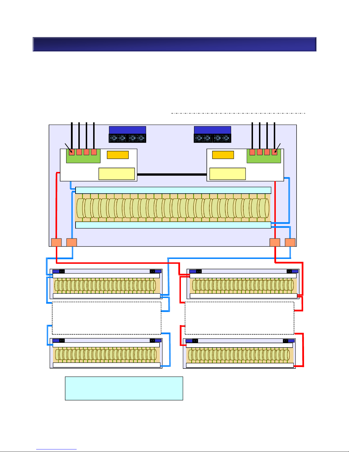
(4-3) DE Connection
The Disk Array Unit can be connected up to the maximum number of DE shown below. DE starts from
“01” because functionality equivalent to “DE 00” is built into DAC. The figure below shows how to
connect DEs and the DE numbers and PD numbers.
28
NEC Confidential
DP0-OUT
DP0-IN
DP0-IN
DP0
Disk Enclosure ・・・・・・・・
Disk Array Unit ・・・・・・・・
:Mini SAS HD cable
Disk Enclosure ・・・・・・・・
2.5” 3.5”
- DE09
- DE08
- DE07
- DE06
- DE05
DE04 DE04
DE03 DE03
DE02 DE02
DE01 DE01
DAC(DE00) DAC(DE00)

2. M110 Component Selection (24)
(5) Dummy HDD
It is required to include a dummy HDD in a empty slot of a base unit and a disk enclosure. Dummy
HDD is not included with a base unit nor disk enclosure. Purchase the required number of dummy
HDD.
Model Number Product Name Accessories
NF9100-CZ59 Dummy HDD Tray (2.5”) x 1
• List of accessories
NF9100-CZ59P Dummy HDD Tray (2.5”) x 24
• List of accessories
NF9100-CZ55 Dummy HDD Tray (3.5”) x 1
• List of accessories
NF9100-CZ55P Dummy HDD Tray (3.5”) x 24
• List of accessories
M110 are equipped with two LAN ports per Disk Array Unit. (M110 can be configured for single
controller configuration. In this case, one LAN port.) Management LAN port supports the following:
• 10BASE-T/100BASE-T/1000BASE-T (Auto-negotiation)
• SNMP protocol (Version 1/2c/3)
• NEC StorageManager
• CLI commands via Telnet/SSH
• Network connector RJ-45
• Floating IP
(7) Management LAN Port
Front bezel is not included with the M-Series Disk Array Unit (both base unit and disk enclosure). If
desired, purchase it separately.
(6) Front Bezel
Model number Product name Figure Remarks
NF9100-SF22E Front Bezel
29
NEC Confidential

M310 Component Selection
30
NEC Confidential
2. M310 Component Selection (1)
n Structure
M310 is a compact and low-end disk storage system in NEC Storage M-Series. M310 has the following
host interfaces: 8/16Gb FC, 1/10Gb iSCSI, Combo(FC and iSCSI). The units support 12x 3.5” drives
and 24x 2.5” drives per 2U chassis. M310 can include a mix of SAS disk drives and Nearline SAS disk
drives. Disk drives can be added to the maximum 240x 3.5” disk drives and 480x 2.5” disk drives by
connecting disk enclosures.
n Overview: M310 Disk Array (2.5)
31
NEC Confidential
Controller
BBU
Base Unit
SAS HDD/SAS SSD
Controller
Cache
12/24GB
BBU
Cache
12/24GB
DE#00(Build-in)
Switch
Switch
SAS HDD/SAS SSD
Switch
Switch
SAS HDD/SAS SSD
Switch
Switch
SAS HDD/SAS SSD
DE#01 DE#10
・
・
・
DE#09
Switch
Switch
SAS HDD/SAS SSD
・
・
・
DE#19
Host Port Card
Fan
Power Supply
Fan
Power Supply
SFP
SFP
Host Port Card
DISK Port DISK Port
Max. 480 HDDs supported.
Max. 19 disk enclosures.
Max. 10 disk enclosures per disk port.

2. M310 Component Selection (2)
n Overview : M310 Disk Array (3.5”)
32
NEC Confidential
Controller
BBU
Base Unit
NL-SAS HDD/SAS SSD
Controller
Cache
12/24GB
BBU
Cache
12/24GB
DE#00(Build-in)
DISK Port
Switch
Switch
NL-SAS HDD/SAS SSD
Switch
Switch
NL-SAS HDD/SAS SSD
Switch
Switch
NL-SAS HDD/SAS SSD
DE#01 DE#10
・
・
・
DE#09
Switch
Switch
NL-SAS HDD/SAS SSD
・
・
・
DE#19
Host Port Card
Fan
Power Supply
Fan
Power Supply
SFP
SFP
Host Port Card
DISK Port
Max. 240 HDDs supported.
Max. 19 disk enclosures.
Max. 10 disk enclosures per disk
port.

2. M310 Component Selection (3)
n Steps for Component Selection When Purchasing a New System
(5) Select Disk Enclosure (Number, Type, Power)
2.5” 3.5”
Refer to (2-1) Disk
Array Unit, a) Base
Unit
(1) Select Model of Disk Array Unit (Power/Disk Size)
(4) Select Disk Drive
(Type, Capacity, Number, Function/Hot Spare Disk)
2.5” 3.5”
Select Encryption
Function
SAS SSD NL-SAS SSD
Select Encryption
Function
Refer to (5) Disk
Enclosure
Refer to (2-1) Disk
Array Unit, b) Host
Port Card
Refer to (4-1) Disk
Drive
(2) Host Port Card (Host I/F)
(9) Select Rack
(8) Select Front Bezel
Refer to (8) Front
Bezel
Refer to 3. Rack Guide
(7) Select Dummy HDD
Refer to (7) Dummy
HDD
33
NEC Confidential
FC/10Gb iSCSI Combo
8Gb FC 16Gb FC
10Gb iSCSI(Copper)
10Gb iSCSI(Optical)
Power Supply(AC,DC)
n Steps for Expansion
Expand Disk
Capacity
(4)Select Disk Drive
(7)Select Dummy HDD
(5)Select Disk Enclosure
(8)Select Front Bezel
(9)Select Rack
2.5” 3.5”
Refer to (3) NEC
Storage Manager
(3) Select Basic Software
(6) Select Cache Capacity
Refer to (6) Cache
Memory, c) Cache
Capacity Expansion

2. M310 Component Selection (4)
(1) System Requirement and Recommended Product
An M310 Disk Array Unit does not include disk drives. A controller unit is not included with a base unit.
Both the array controller unit and a controller card are required. The following steps and lists are
references for choosing an appropriate product combination.
If FC, choose 8/16Gb FC 8 ports.
If 1Gb iSCSI, choose 1Gb iSCSI Copper 8 ports.
If 10Gb iSCSI, choose 10Gb iSCSI Copper/Optical 8 ports.
If Combo, choose 8/16Gb FC 4 ports and 1/10Gb iSCSI
Copper/Optical 4 ports.
Refer to M310 Component Selection (2-1): Product List,
b) Controller Card
Ø Refer to M310 Component Selection (2-3) Choose Host
I/F
Choose cache memory
Ø Refer to M310 Component Selection (6): Cache Memory
YES
NO
YES
(3) Cache capacity is
determined.
YES
(2) Space-saving is
required.
(1) Host I/F is determined.
Choose M310 Disk Array Unit (2.5” model)
Ø Refer to M310 Component Selection (2-1): Product List,
a) Base Unit
34
NEC Confidential

2. M310 Component Selection (5)
(2) Disk Array Unit
(2-1) Disk Array Unit
Model Number Product Name Remarks
Accessories
*1
NF5332-SR01E
M310 Disk Array
Unit (2.5”)
• Power supply unit
AC 100-240V
• 24 x 2.5” disk drives
• NEC Storage Rack Mount Kit
• List of accessories
• Ear Bezels *2(left and right)
• HW Document CD (User Guide,
Setup Guide, Installation Guide)
NF5332-SR00E
M310 Disk Array
Unit (3.5”)
• Power supply unit
AC 100-240V
• 12 x 3.5” disk drives
NF5332SR01DE
M310 Disk Array
Unit (2.5”) (DC
48V)
• Power supply unit
DC 48V
• 24 x 2.5” disk drives
• NEC Storage Rack Mount Kit
• List of accessories
• Ear Bezels *2(left and right)
• HW Document CD (User Guide,
Setup Guide, Installation Guide)
• DC Cables
NF5332SR00DE
M310 Disk Array
Unit (3.5”) (DC
48V)
• Power supply unit
DC 48V
• 12 x 3.5” disk drives
a) Base Unit
*1No front bezel is attached on M-Series Disk Array Units. Purchase the bezel separately if required.
*2Ear bezels indicate the black cover panels at both ends of base unit.
35
NEC Confidential
Model
Number
Product Name Remarks Accessories
NF5322-
SF06E
Host Port Card
(FC 4Port)
Host Port card x 1(SFP module-less)
- Blank slot x4 for FC SFP
List of
accessories
NF5322-
SF22E
Host Port Card
(10Gb iSCSI optical 4Port)
Host Port card x 1(SFP module-less)
- Blank slot x4 for 10Gb iSCSI optical SFP
List of
accessories
NF5322-
SF24E
Host Port Card
(10Gb iSCSI Copper 4Port)
Host Port card x 1
- 10Gb iSCSI Copper 4port
List of
accessories
NF5322-
SF83E
Host Port Card
(FC/10Gb iSCSI Optical Combo)
Host Port card x 1
- Blank slot x2 for FC SFP
- Blank slot x2 for 10Gb iSCSI optical SFP
List of
accessories
NF5322-
SF84E
Host Port Card
(FC/10Gb iSCSI Copper Combo)
Host Port card x 1
- Blank slot x2 for FC SFP
- Blank slot x2 for 10Gb iSCSI copper
List of
accessories
b) Host Port Card
Ear bezel Ear bezel

NEC Confidential
36
2. M310 Component Selection (6)
Model Number Product Name Remark
NF5322-SFP08E SFP Module(8Gb FC) SFP module 8Gb FC x2
NF5322-SFP16E SFP Module(16Gb FC) SFP module 16Gb FC x2
NF5322-SFP10E SFP Module(10Gb iSCSI Optical) SFP module 10Gb iSCSI Optical x2
■SFP(Small Form factor Pluggable) module
SFP module is kind of the transceiver to communicate in a Fibre channel or Gigabit Ethernet. The
connection of the apparatus is enabled by putting it on Host Port Card. Therefore, the arrangement of
the SFP module becomes required.
(2-2) SFP Module for FC, iSCSI(Optical), and Combo
In case of SFP module-less host port card, it is required to purchase appropriate SFP module.
Refer to the following table and available SFP module combination on next page for appropriate
SFP type and quantity.

Port
combination
per unit
8Gb FC SFP
[NF5322-SFP08E]
16G FC SFP
[NF5322-SFP16E]
8G FC 2Port 1 0
8G FC 4Port 2 0
8G FC 6Port 3 0
8G FC 8Port 4 0
16G FC 2Port 0 1
16G FC 4Port 0 2
16G FC 6Port 0 3
16G FC 8Port 0 4
8G FC 2Port
16G FC 2Port
1 1
8G FC 2Port
16G FC 4Port
1 2
8G FC 2Port
16G FC 6Port
1 3
8G FC 4Port
16G FC 2Port
2 1
8G FC 4Port
16G FC 4Port
2 2
8G FC 6Port
16G FC 2Port
3 1
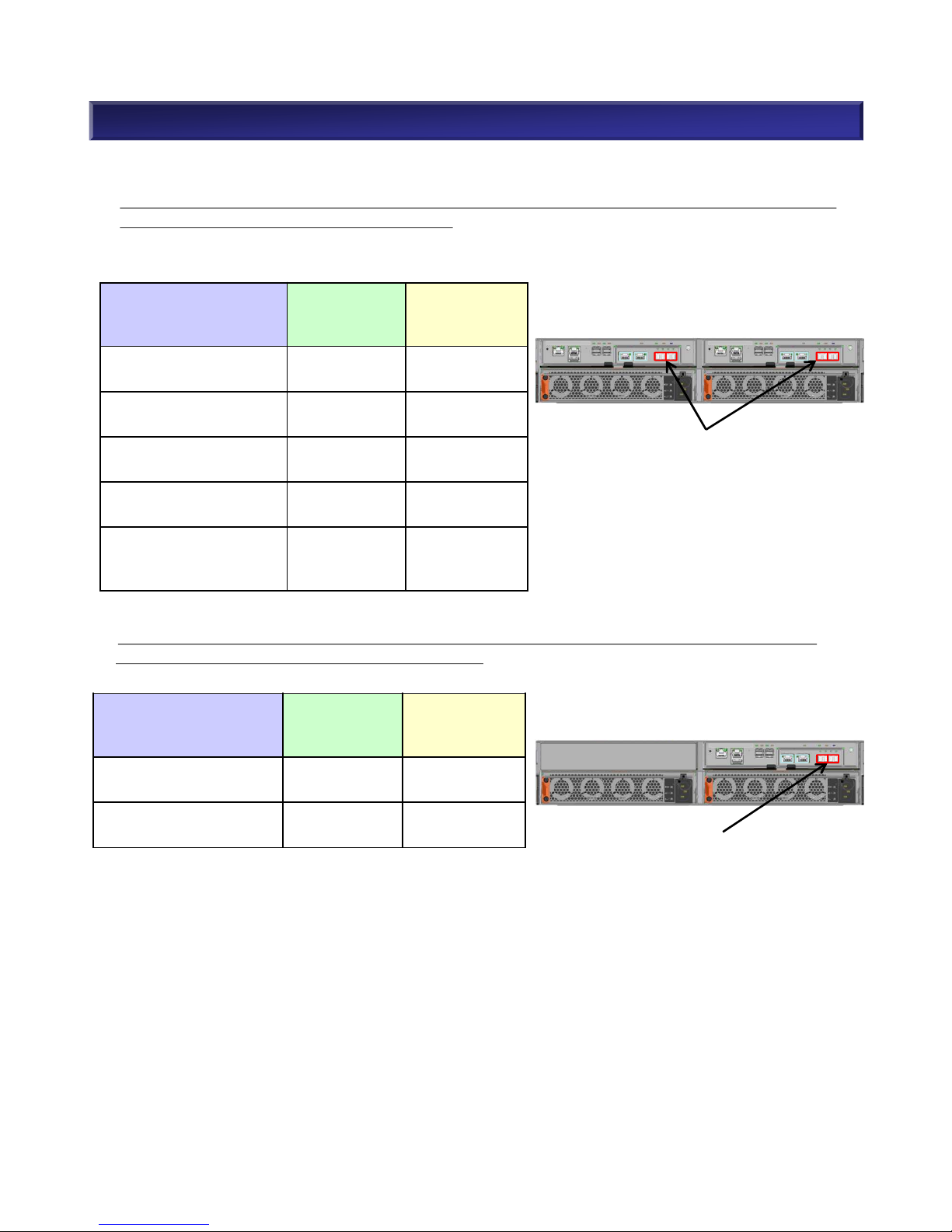
■Available SFP Module combination for Host Port Card(FC 4Port) [NF5322-SF06E]
The following table shows available SFP combination in case of M310 disk array(dual controller)
with two Host Port Card(FC 4Port).
Max 8 SFPs (corresponded to 4-Model
Number) per unit are available.
2. M310 Component Selection (7)
M310 M310
※Caution for installation of FC SFP module
Mixed installation with 8Gb FC SFP and 16Gb FC SFP is available. However, you need to install each
SFP at the same position when you set up dual controller configuration.
Controller 1
Host Port Card
Port0 Port1 Port2 Port3
・・・SFP module (8Gb FC)
・・・SFP module 16Gb FC)
Controller 1
Host Port Card
Port0 Port1 Port2 Port3
Controller 0
Host Port Card
Port0 Port1 Port2 Port3
Controller 0
Host Port Card
Port0 Port1 Port2 Port3
NEC Confidential
37
NG
Good

■Available SFP Module combination for Host Port Card(10Gb iSCSI Optical 4Port) [NF5322-SF22E]
The following table shows available SFP combination in case of M310 disk array(dual controller)
with two Host Port Card(10Gb iSCSI Optical 4Port).
Port combination
per unit
10Gb iSCSI Optical SFP
[NF5322-SFP10E]
10G iSCSI Optical
2Port
1
10G iSCSI Optical
4Port
2
10G iSCSI Optical
6Port
3
10G iSCSI Optical
8Port
4
2. M310 Component Selection (8)
Max 8 SFPs (corresponded to 4-Model
Number) per unit are available.
NEC Confidential
38
■ Available SFP Module combination for Host Port Card(FC/10Gb iSCSI Optical) [NF5322-SF83E]
The following table shows available SFP combination in case of M310 disk array(dual controller) with
two Host Port Card(FC / 10Gb iSCSI Optical).
Port combination
per unit
8Gb FC SFP
[NF5322-SFP08E]
16G FC SFP
[NF5322-SFP16E]
10Gb iSCSI Optical SFP
[NF5322-SFP10E]
8G FC 2Port
10G iSCSI Optical 2/4Port
1 0 1 or 2
8G FC 4Port
10G iSCSI Optical 2/4Port
2 0 1 or 2
16G FC 2Port
10G iSCSI Optical 2/4Port
0 1 1 or 2
16G FC 4Port
10G iSCSI Optical 2/4Port
0 2 1 or 2
8G FC 2Port
16G FC 2Port
10G iSCSI Optical 2/4Port
1 1 1 or 2
Max 4 iSCSI SFPs (corresponded to 2Model Number) per unit are available.
Max 4 FC SFPs (corresponded to 2Model Number) per unit are available.

■ Available SFP Module combination for Host Port Card(FC/10Gb iSCSI Copper) [NF5322-SF84E]
Host Port Card(FC/10Gb iSCSI Copper) initially has 2 port of 10Gb iSCSI Copper.
The following table shows available SFP combination in case of M310 disk array(dual controller) with
two Host Port Card(FC / 10Gb iSCSI Copper).
Port combination
per unit
8Gb FC SFP
[NF5322-
SFP08E]
16G FC SFP
[NF5322-
SFP16E]
8G FC 2Port
10Gb iSCSI Copper 4Port
1 0
8G FC 4Port
10Gb iSCSI Copper 4Port
2 0
16G FC 2Port
10Gb iSCSI Copper 4Port
0 1
16G FC 4Port
10Gb iSCSI Copper 4Port
0 2
8G FC 2Port
16G FC 2Port
10Gb iSCSI Copper 4Port
1 1
Unit with two FC/10Gb iSCSI Copper Host
Port Card, has initially four 10 Gb iSCSI
Copper ports.
2. M310 Component Selection (9)
Max 4 FC SFPs (corresponded to 2Model Number) per unit are available.
NEC Confidential
39
(2-3) Choose Host I/F
• 16/8Gb FC: High speed interface
• 10Gb iSCSI(Optical): High speed and easy connection interface
• 10Gb iSCSI(Copper): Lower 10Gb iSCSI(Optical).High speed and easy connection interface
• 1Gb iSCSI: Low cost and easy connection interface
• 16Gb FC and 10Gb iSCSI : Combo

2. M310 Component Selection (10)
NEC StorageManager software performs basic and advanced storage management functions. It is a
base product that manage multiple arrays from a single point. It requires a management server.
Refer to the table below for functions which are available with NEC StorageManager
.
NEC StorageManager functions
Supported Storage
M310
Monitor multiple storages
○
Linkage with ESMPRO
○
Linkage with SigmaSystemCenter
○
Event Link (Report by e-mail. Run executable)
○
Monitor performance [NEC Storage PerformanceMonitor]
○
Analyze performance [NEC Storage PerformanceNavigator]
○
Alert (Express Alert, cooperate with syslog)
○
In-box replication [NEC Storage DynamicDataReplication]
○
Inter-box replication [NEC Storage RemoteDataReplication]
○
*1
Prevent unauthorized access or modification of data [NEC
Storage VolumeProtect]
○
(3) NEC StorageManager
40
NEC Confidential
*1FC and iSCSI host I/F are supported. SAS host I/F is not supported.
○:Supported -:Not supported

(4-2) Disk Capacity
(Considerations for System Volume)
A system volume, in which performance logs, etc. are automatically saved, is created in the first
binding Pool. System volume capacity is 8.0 GB. (or 8.6GB if 1KB = 1000Byte)
(Considerations for Snapshot)
When using the snapshot feature, it is necessary to create a snapshot reservation area for replication
of a master volume (snapshot).
(Considerations for Replication)
When implementing the replication feature, use the storage system information retention function* and
create a replication reserved volume with the NEC StorageManager application. The capacity of a
replication reserved volume is 8.0GB. (or 8.6GB if 1KB = 1000Byte)
When turning power off via a planned shutdown all storage system information (differential map, etc)
will be backed up onto the replication reserved volume only if it was configured. If the replication
reserved volume is not configured then storage system information will be lost on shutdown. When
restarting after a planned shutdown, I/O load will be generated as data on the MV is fully copied to the
RV. This startup load may be large enough to temporarily affect performance. It is recommended to
operate 24 hours nonstop, especially if running without a replication reserved volume.
* Storage system information retention function is used to backup storage system information such as
the differential map between business volume (MV) and replication volume (RV) onto disk drives.
2. M310 Component Selection (11)
When deciding how many disk drives are required, remember that logical disk capacity varies
depending on both disk drive type (I/F, capacity) and RAID type. The amount of required logical disk
capacity varies depending on the amount of data usage and whether or not specific features (Snapshot,
Replication) are required. Using estimated logical disk capacity and desired performance, the number
of disk drives can be estimated. Include all relevant topology factors (I/F, capacity, rotation speed,
RAID type) when calculating capacity. A minimum of three disk drives is required.
Refer to “(4-4) Supported RAID” for supported RAID types.
(4) Disk Drive
(4-1) Disk Drive
Slots #00, #01, and #02 must be populated.
41
NEC Confidential
#00 #01 #02 #03
#04 #05 #06 #07
#08 #09 #0A #0B
#17
・・・
#00
#01
#02
#03

NEC Confidential
42
Considerations for Lifetime of Disk Drive
・Lifetime of SAS HDD, Nearline SAS HDD and SAS SSD are 5 years.
2. M310 Component Selection (12)
2. M310 Component Selection (13)
43
NEC Confidential
(4-3) Disk Drive Type
Select a disk drive type from the following table and decide how many drives are needed.
Model Number Product Name
NF5322-SMA75E SAS Disk Drive(2.5" 15krpm/300GB )
NF5322-SMA78E SAS Disk Drive(2.5" 15krpm/600GB )
NF5322-SMA78LE
*1
SAS Disk Drive(2.5" 15krpm/600GB Self-encrypting)
NF5322-SM768E SAS Disk Drive(2.5" 10krpm/600GB )
NF5322-SM768LE
*1
SAS Disk Drive(2.5" 10krpm/600GB Self-encrypting)
NF5322-SM76AE SAS Disk Drive(2.5" 10krpm/1.2TB )
NF5322-SMB6CE
*3
SAS Disk Drive(2.5" 10krpm/1.8TB)
NF5322-SSAG5E
*2
SAS SSD (2.5" 200GB)
NF5322-SSAG5LE
*1 *2 *3
SAS SSD(2.5" 200GB Self-encrypting)
NF5322-SSA96E
*2
SAS SSD (2.5” 400GB)
NF5322-SSA9AE
*2
SAS SSD (2.5” 1.6TB)
NF5322-SMA75GE SAS Disk Drive(2.5" 15krpm/300GB ) x 10 pcs
NF5322-SMA78GE SAS Disk Drive(2.5" 15krpm/600GB ) x 10 pcs
NF5322-SMA78LGE
*1
SAS Disk Drive(2.5" 15krpm/600GB Self-encrypting) x 10pcs
NF5322-SM768GE SAS Disk Drive(2.5" 10krpm/600GB ) x 10 pcs
NF5322-SM768LGE
*1
SAS Disk Drive(2.5" 10krpm/600GB Self-encrypting) x 10 pcs
NF5322-SM76AGE SAS Disk Drive(2.5" 10krpm/1.2TB) x 10 pcs
NF5322-SMB6CGE
*3
SAS Disk Drive(2.5" 10krpm/1.8TB) x 10 pcs
NF5322-SSAG5GE
*2
SAS SSD (2.5" 200GB) x 10 pcs
NF5322-SSAG5LGE
*1 *2 *3
SAS SSD(2.5" 200GB Self-encrypting) x 10 pcs
NF5322-SSA96GE
*2
SAS SSD (2.5” 400GB) x 10 pcs
NF5322-SSA9AGE
*2
SAS SSD (2.5” 1.6TB) x 10 pcs
NF5322-SM708E NL-SAS Disk Drive(3.5" 7.2krpm/2TB)
NF5322-SM70AE NL-SAS Disk Drive(3.5" 7.2krpm/4TB)
NF5322-SM70ALE
*1
NL-SAS Disk Drive(3.5" 7.2krpm/4TB Self-encrypting)
NF5322-SMB0CE
*3
NL-SAS Disk Drive(3.5" 7.2krpm/6TB)
NF5322-SSAR5E
*2
SAS SSD (3.5" 200GB )
NF5322-SSAR5LE
*1 *2 *3
SAS SSD(3.5" 200GB Self-encrypting)
NF5322-SSAF6E
*2
SAS SSD (3.5" 400GB )
NF5322-SSAFAE
*2
SAS SSD (3.5" 1.6TB)
NF5322-SM708GE NL-SAS Disk Drive(3.5" 7.2krpm/2TB) x 10 pcs
NF5322-SM70AGE NL-SAS Disk Drive(3.5" 7.2krpm/4TB) x 10 pcs
NF5322-SM70ALGE
*1
NL-SAS Disk Drive(3.5" 7.2krpm/4TB Self- encrypting) x 10 pcs
NF5322-SMB0CGE
*3
NL-SAS Disk Drive(3.5" 7.2krpm/6TB) x 10 pcs
NF5322-SSAR5GE
*2
SAS SSD (3.5" 200GB) x 10 pcs
NF5322-SSAR5LGE
*1 *2 *3
SAS SSD(3.5" 200GB Self-encrypting) x 10 pcs
NF5322-SSAF6GE
*2
SAS SSD (3.5" 400GB) x 10 pcs
NF5322-SSAFAGE
*2
SAS SSD (3.5" 1.6TB) x 10 pcs
*1 Encrypted HDDs are not supported in China
*2 In general, lead time of SSD is longer than lead time of HDD. When you order the SSD,
please consider two to three months lead time to get the SSD.
*3 Storage Control Software Revision 0920 or above, and NEC StorageManager Ver9.2 or
above are required.

2. M310 Component Selection (14)
(4-5) Supported RAID
NEC Storage M-Series supports the following RAID types. (Note: Only RAID-1, 10, 5/50(4+P),
6/60(4+PQ), 6/60(8+PQ) are supported with SSD)
(4-6) Dynamic Pool
NEC Storage M-Series supports only dynamic pools. LUN capacity can be modified dynamically.
Capacity is constant regardless of the number of disk drives. It is slightly less than the table above.
Striping is automatic when an applicable number of disk drives are used with RAID types that support it.
<Example> RAID-1 with 4 disk drives is automatically configured as RAID-10.
Refer to “5. Functions <Pool>” for more details about dynamic pool.
* RAID-0: Data is not protected.
RAID Type Configuration Number of physical disk drives Redundancy RAID Capacity
RAID-0 * None Physical disk capacity x 1
RAID-1/10 (1+1) x n 2 or more disk drives 1 Physical disk capacity x 1/2
RAID-5/50 (2+P) x n 3 or more disk drives 1 Physical disk capacity x 2/3
(4+P) x n 5 or more disk drives 1 Physical disk capacity x 4/5
(8+P) x n 9 or more disk drives 1 Physical disk capacity x 8/9
RAID-6/60 (4+PQ) x n 6 or more disk drives 2 Physical disk capacity x 2/3
(8+PQ) x n 10 or more disk drives 2 Physical disk capacity x 4/5
RAID-TM (1+1+1) x n 3 or more disk drives 2 Physical disk capacity x 1/3
(4-4) Disk Drive Usage
Both the base unit and SAS disk enclosures can include a mix of SAS disk drives/NL-SAS disk
drives/SAS SSD and disk drives with different capacities and rotation speeds.
A pool must contain disk drives with the same interface. The capacity or rotation speed does not matter.
However, it is strongly recommended to use devices of the same capacity and same rotation speed in
a pool. When using different capacities of disk drive in a pool, the pool will be created based on the
disk drive with the smallest capacity. In this case, the rest of larger disk drives are not available.
Since SAS and Nearline SAS are regarded as different interfaces, it is impossible to mix SAS and
Nearline SAS in same pool. Also mix of HDD and SSD, mix of self-encrypting HDD and non-encrypting
HDD is not available in same pool. For SSD, It is recommended to mix same SSD type and same
capacity.
<Example>
A pool configured by SAS disk drives (15krpm/300GB) and SAS disk drives (15krpm/600GB)
ØThe SAS disk drive (15krpm/600GB) is treated as a SAS disk drive (15krpm/300GB).
When using different speeds of disk drives in a pool, the pool will be created based on the slowest disk
speed. In this case, performance will not be as good as expected because drives with faster speed are
treated the same as drives with the slowest speed.
<Example>
A pool configured by 3.5” SAS disk drives (15krpm/600GB) and 2.5” SAS disk drive(10krpm/600GB)
ØThe SAS disk drive (15krpm/600GB) is treated as a SAS disk drive (10krpm/600GB).
44
NEC Confidential

2. M310 Component Selection (15)
(4-7) Hot Spare Disk
When assigning hot spare disks:
• Assigning a hot spare disk enables automatic restoration of data without waiting for a maintenance
service agent in the event of disk failure. Data redundancy is recovered when restoring the data to
the hot spare.
• M-Series has a “Preventive maintenance function” that moves data to hot spare disks before a disk
failure occurs by detecting symptoms of the failure in order to maintain redundancy.
• It is strongly recommended to assign a hot spare disk in order to enhance the availability of disk array
units.
• M-Series has a global hot spare function which enables hot spare disks to be used with any
HDD/SSD.
• SSD hot spare is only good with SSDs. SSD cannot be used as a hot spare with HDDs. Likewise,
HDD cannot be used as a hot spare with SSDs.
• When multiple types of disk drives are defined as hot spare disks, the priority is as follows.
1. The same interface, the same capacity and the same rotation speed as the base disk drive*.
2. The same interface, the same capacity as the base disk drive* but the slower disk used first
when multiple speeds of hot spare drives exist.
3. The same interface as the base disk drive*, but larger than the base disk drive*. When multiple
sizes of hot spare disks exist, the smaller disk is used first.
* Base disk drive = disk drive with the smallest capacity/slowest rotation speed in the pool.
• The number of recommended hot spares varies depending on the disk drive type. Refer to the table
below.
Disk drive type Condition Recommendation
SAS Disk Drive
One type of capacity/rotation speed One hot spare drive / 24 disk drives
n types of capacity/rotation speed n spare disk drives / 24 disk drives
NL-SAS Disk Drive *
1
One type of capacity/rotation speed One hot spare drive / 12 disk drives
n types of capacity/rotation speed n spare disk drives / 12 disk drives
SAS SSD
Hot spare is optional. Because SAS SSD does not have mechanical parts
such as motors, heads and media, it is reliable. Assign hot spare disks as a
customer requests.
Refer to “5. Functions <Hot Spare Disk>” for more details about hot spare disks.
*1
Must assign hot spare disks when NL-SAS disk drives are in the system.
<Example>
Data
HSP
Data
Data Data
Data Data
Data
Data
DataData Data
11 x Data disks
1 x Hot spare disk
45
NEC Confidential
23 x Data disks
1 x Hot spare disk
HSP: Hot spare diskData: Data disk
Data
Data
Data
Data
HSP
Data
Data
・・・

2. M310 Component Selection (16)
Select a disk enclosure below when you need more disk drives than the base unit. And when you use
disk drive of different form factor from the base unit, optional disk enclosures are required.
Model Number Product Name
Cable
Length
Remarks
NF9120-SJ93 Mini SAS HD Cable (3m) 3m
2 x Mini SAS HD cable
(Host-DAC / DAC-DE / DE-DE )
NF9120-SJ95
Mini SAS HD Cable (5m)
DE-to-DE only
5m
2 x Mini SAS HD cable
( DE-DE only )
When several disk enclosures are placed in different racks, a Mini SAS HD cable (1m) will not be long
enough and the Mini SAS HD cable in the table below will be needed.
Model number Product name
Max. num of
disk drives
Power supply Accessories
NF5322-SE81E
Disk Enclosure
(2.5”, 6/12Gpbs)
24 AC100V - 240V
Mini SAS HD cable (1m)
Ear Bezel
NEC Storage Rack Mount Kit
List of accessories
x 2
x 2
x 1
x 1
NF5322-SE80E
Disk Enclosure
(3.5”, 6/12Gpbs)
12 AC100V - 240V
NF5322-SE81DE
Disk Enclosure
(2.5”, 6/12Gpbs)
24 DC 48V
Mini SAS HD cable (1m)
Ear Bezel
NEC Storage Rack Mount Kit
List of accessories
DC Cables
x 2
x 2
x 1
x 1
x 2
NF5322-SE80DE
Disk Enclosure
(3.5”, 6/12Gpbs)
12 DC 48V
(5) Disk Enclosure
46
NEC Confidential

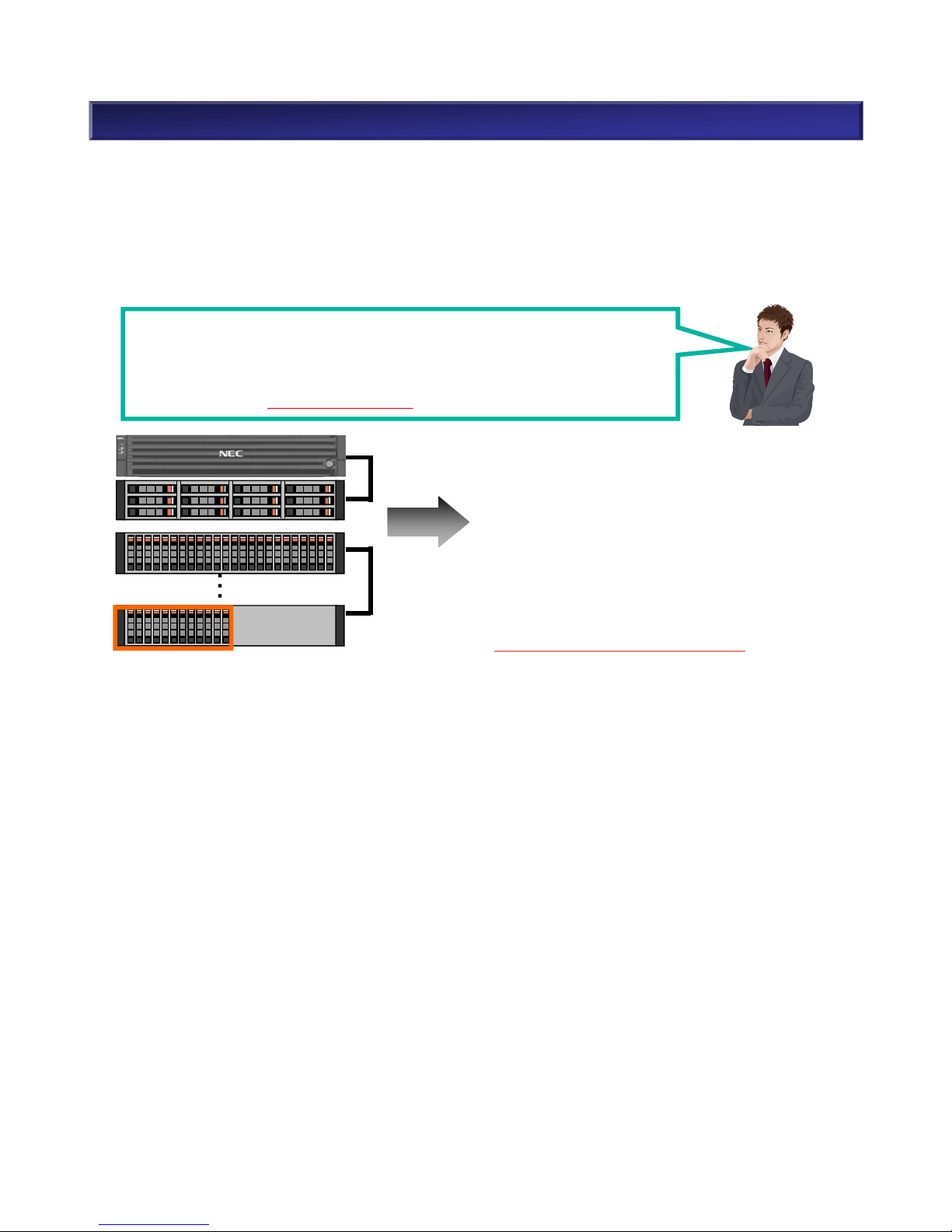
2. M310 Component Selection (17)
【CAUTION: The Number of Disk Enclosures】
M-Series can use a mix of 3.5” and 2.5” disk enclosures at the same time.
The sum of available disk drive slots in both base unit and disk enclosures must not exceed the
supported maximum number of disk drives. Note: Even if a disk drive slot is blank, it is still counted.
For example:
I would like to use 312 disk drives in base unit (3.5”) , fifteen disk enclosures (3.5”)
and five disk enclosures (2.5”).
1 x 3.5” base unit: 12 disk drives in base unit
15 x 3.5” disk enclosures: 12 disk drives in disk enclosures
5 x 2.5” disk enclosures: 24 disk drives in disk enclosures
Is this supported? → No, it is not supported.
Max. number of disk drives of 3.5” base unit: 12
Max. number of disk drives of 2.5” disk enclosure: 24
12 (base unit) + (12 X 15) + (24 X 5) = 312 disk drive slots
15 + 5 = 20 disk enclosures
M310 Disk Array supports disk drives up to 480.
However, the sum of disk enclosures (20) exceeds the
supported maximum number of disk enclosures (19).
→ This configuration is not supported.
47
NEC Confidential
・
・
・
DAC×1
2.5”DE×5
3.5”DE×15

DP0DP1
Max Connection
DP0: 9 DP1 : 10
・・・ Mini SAS HD Cable(1m)
・・・ Mini SAS HD Cable(3m)
DAC
DP0DP1
DE connection
2. M310 Component Selection (18)
NEC Confidential

NEC Confidential
49
2. M310 Component Selection (19)
(6) Cache Memory
It is required to purchase cache memory for M310 disk array unit. Refer the following table when
purchasing it.
a) Cache Model at Purchase
Mode Number Product Name Remarks
NF5332-SC01SE Standard Cache Memory (12GB) Standard Cache Memory (12GB) for M310
NF5332-SC02SE Standard Cache Memory (24GB) Standard Cache Memory (24GB) for M310
b) Cache Capacity Expansion
Cache memory can provide better performance by improving access times to frequently accessed data
and can significantly improve on write performance. In order to reduce the occurrence of cache
overflow conditions in high performance environments, it is recommended to expand cache to
maximum 48GB.
(i) Cache Saturation (ii) Cache Expansion
Usage
Cache
♪
Not
Saturated
・・・
・・・
♪
Usage
Cache
Cache
(Saturated by Usage)
・・・
…
The following table describes recommended cache capacity.
c) Cache Capacity Selection
Logical disk capacity (GB) Recommended cache capacity Number of Cache Memory
*1
Up to 26TB
24GB Standard Cache Memory (12GB) x 2
More than 26TB
48GB Standard Cache Memory (24GB) x 2

2. M310 Component Selection (20)
(7) Dummy HDD
It is required to include a dummy HDD in a empty slot of a base unit or a disk enclosure. No dummy
HDD is not included with a base unit nor disk enclosure. Purchase the required number of dummy
HDD separately.
M310 are equipped with two LAN ports per Disk Array Unit.
Management LAN port supports the following:
• 10BASE-T/100BASE-T/1000BASE-T (Auto-negotiation)
• SNMP protocol (Version 1/2c/3)
• NEC StorageManager
• CLI commands via Telnet/SSH
• Network connector RJ-45
• Floating IP
(9) Management LAN Port
No front bezel is included with the M-Series Disk Array Unit (both base unit and disk enclosure). If
desired, purchase it separately.
(8) Front Bezel
Model number Product Name Figure Remarks
NF9100-SF22E Front Bezel
50
NEC Confidential
Model Number Product Name Accessories
NF9100-CZ59 Dummy HDD Tray (2.5”) x 1
• List of accessories
NF9100-CZ59P Dummy HDD Tray (2.5”) x 24
• List of accessories
NF9100-CZ55 Dummy HDD Tray (3.5”) x 1
• List of accessories
NF9100-CZ55P Dummy HDD Tray (3.5”) x 24
• List of accessories

3. Rack Guide
Mount in a Rack
(1) Disk Array Units do not exceed the maximum loading weight of the rack. The heavier unit is
mounted in the bottom of the rack.
(2) Each unit is mounted from the bottom with no space between. The monitor/keyboard can be
positioned in the convenient level.
Caution: When mounting the units deeper than DAC or DE in M-Series Disk Array, one above the
other, allow 1U space over or below.
When mounting M-Series Disk Array in a rack, the following guidelines must be considered.
M-Series Disk Array Size
The height of storage units is standardized as “U”(1U=44.45mm/1.75inches) by EIA. Rack-mounting
described below is based on the U number.
M-Series
Disk Array
Disk Array Controller (DAC) Disk Enclosure (DE)
M110/M310
Height 2U 2U
Depth 556.0mm/21.89inches 548.5mm/21.59inches
M110/310 Disk Array : Height and Depth
Front
Front
Not enough
Space in between!
Side view
Front
Unit deeper than M-Series Disk Array
Unit deeper than M-Series Disk Array
M-Series Disk Array (DAC/DE)
Rear
Improper Mount
Enough space in
between!
Proper Mount (Example 1)
Side view
Unit deeper than M-Series Disk Array
Unit deeper than M-Series Disk Array
M-Series Disk Array (DAC/DE)
Rear
1U space
Side view
Unit deeper than M-Series Disk Array
Unit deeper than M-Series Disk Array
M-Series Disk Array (DAC/DE)
Rear
1U space
Proper Mount (Example 2)
Enough space in
between!
51
NEC Confidential

4. Disk Drive (1)
(1) Disk Drive Size and Type
M-Series products support the following types of drives: SSD, SAS, and NL-SAS. Performance,
reliability, and price of disk drives vary depending on the type and size. Select the proper disk drive
according to the intended application.
(1-1) Disk Drive Size
There are two relevant form factors of disk drives: 2.5” and 3.5”.
■ 2.5” HDD
The maximum rotation speed is 15krpm for a high performance HDD.
2U chassis can support up to 24 HDDs.
■ 3.5” HDD
The larger 7.2krpm NL-SAS drive topology offers an excellent cost per capacity ratio.
(1-2) Disk Drive Type
n SSD (Solid State Drive)
Unlike a conventional HDD, SSD does not have mechanical parts such as motors, heads and media.
Reliability and random access performance is superior to conventional HDD. SSD is a “green” product
because it reduces power consumption.
- SAS SSD: High performance, High reliability
n SAS HDD (Serial Attached SCSI Hard Disk Drive)
SAS HDD is excellent in reliability and performance. It is good for mission-critical systems that require
high-performance and non-stop operation.
n NL-SAS HDD (NL-Serial Attached SCSI Hard Disk Drive)
NL-SAS is a high capacity and low cost HDD. It is good for backup and archive and can be used for
workloads which do not require high volumes of random access I/O. Because NL-SAS HDD has large
capacity and low performance, it takes longer time to recover compared to SAS HDD.
From the perspective of reliability, double redundancy RAID types such as RAID-6 or RAID-TM
are recommended.
I/F Name SAS SSD NL-SAS (3.5”) SAS (2.5”)
Rotation s peed
-
7.2krpm 10krpm 15krpm
Avg. access time 1.0(m/s) 8.2-9.5(ms) 3.8-4.4(ms) 2.9-3.3(ms)
Power consumption ( idle) (AC) Approx. 4W Approx. 9W Approx. 8W
Max. power consumption (AC) Approx. 10W Approx. 14W Approx. 9W
Max. capaci ty 1.6TB 6TB 1.8TB 600GB
BER (Bit error rate) at read - 1/10^15 1/10^16
Random access performance ratio - 1 1.6 2.4
Backup performance ratio - 1 1.5 1.5
Restore performance ratio - 1 1 1.1
Operating time 8 hours/day
365 days
24 hours/day
365 days
Usage • High random access
performance
• High reliability
• Lower noise
• Large capacity
• Backup/archive
• Low workload (low
random access I/O )
• Mi ssion-critical
• High transaction
Note: The table is reference only.
52
NEC Confidential

4. Disk Drive (2)
(2) Disk Drive Usage
In M-Series products, disk enclosures can include a mix of SSD, SAS HDD and NL-SAS HDDs. MSeries products provide more flexibility of choices; SAS Disk Drive for mission-critical systems that
require high-performance and non-stop operation or NL-SAS HDD for systems that require low-cost
and the backup with large capacity.
(2-1) NL-SAS HDD
NL-SAS HDD is ideal for the systems that do not require high performance but large capacity at low
cost as follows:
1. Large data sets (Web, Images, Research and development data, E-mail)
2. Disk backup
3. Archive – Data protection (VolumeProtect)
4. Replication between arrays (RemoteDataReplication) – RV (Replication Volume)
5. Replication within the same array (DynamicDataReplication) – RV (Replication Volume)
6. Snapshot (DynamicSnapVolume) – SV (Snapshot Volume)
7. File Server
(2-2) SAS HDD
SAS HDD is excellent in performance, capacity and reliability. It is ideal for mission-critical systems
that require high-performance at low cost as follows:
1. Frequently accessed database
2. Mission-critical applications
(2-3) SSD
SSD is a higher price and higher performance HDD and ideal for the systems as follows:
Database index
Field applications
Example : SAS/NL SAS
■A mix of SAS/Large Capacity HDD (NL-SAS)
■Configuration only large Capacity HDD(NL SAS)
・Large capacity with low-cost for electronic document law and long-term Storage
Support RDR
SAS SAS
NLSAS
SAS
NLSASNLSAS
Tier2
Tier1
SSD SSD
Tier0
※Need PerforOptimizer
SAS
NLSAS
RDR
(M310/M510/M7 10)
53
NEC Confidential

5. Functions <Pool (1)>
(1-1) Pool
“Pool” is a virtual storage area configured from physical disks using RAID technology. Logical disks
(LUN) can be setup by allocating pool capacity to each logical disk .
(1-2) Pool Type
Pools include Basic Pools and Dynamic Pools.
• Basic Pool
- Basic pools consist of a fixed number of physical disks.
- It is not possible to expand pool size and logical disk capacity.
• Dynamic Pools
Since multiple storage areas in the pool are being managed, the data will be retained when physical
disks are added and storage areas are expanded.
- Pool capacity can be expanded with the existing data retained.
- Logical disk capacity can be expanded with the existing data retained.
- A logical disk allocated from the pool can be immediately used by a production server.
The M-Series products support only dynamic pools, which increases functionality and performance
dynamically as well as delivers simplified operation in system management.
(1) Pool
Pool Disk drives
Logical disks
Server
Create/Delete
LUN LUN LUN
Note:
Since NL-SAS disk drives have a larger capacity with lower rotation speed than traditional SAS, it
requires more rebuilding time when disk failure occurs, which may lead to another failure. RAID
types such as RAID-6 or RAID-TM, which have multiple layers of redundancy, are strongly
recommended because they provide more reliability.
54
NEC Confidential

(2-1) Configuring a pool
It is recommended that a RAID consists of a combination of physical disks of the same capacity and
same rotation speed. The space configured in a pool is available to bind logical disks immediately.
The following list describes minimum and maximum disk drives in a dynamic pool. Refer to “Appendix:
Dynamic Pool Capacity List” for pool capacity.
SSD: RAID-1, 10, 5/50 (4+P), 6/60 (4+P) only.
(2) Pool and Logical Disk: Configuration and Expansion
RAID Type Configuration
Min. number of
disk drives
Capacity utilization
Max. number of
disk drives
RAID-1/10 (1+ 1) x n 2 50%
M110:120
M310:480(2.5”)
240(3.5”)
RAID-5/50
(2 + P) x n 3 66%
(4 + P) x n 5 80%
(8 + P) x n 9 88%
RAID-6/60
(4 + PQ) x 2 6 66%
(8 + PQ) x 2 10 80%
RAID-TM (1 + 1 + 1) x n 3 33%
Note: Striping and the number of HDDs (RAID-10/50/60/TM)
A dynamic pool can be built with any combination of RAID type and number of HDD by using
virtualization technology. Striping is automatic when configuring a pool with more than twice the
minimum number of HDDs in each RAID type. For example, RAID-1 with 4 HDDs is automatically
configured as RAID-10. It is also possible to configure a pool with 3 HDDs in RAID-1, in which case,
it will be equivalent to the striping effect of RAID-10.
Note: Pool Configuration
In M-Series products, a system volume which manages performance logs etc. is automatically created
in the pool first created. The capacity of a system volume is 8.6GB (1GB=10003Byte) / 8.0GB
(1G=10243Byte).
When using DynamicDataReplication, it is recommended to create the master volume (MV) and the
replication volumes (RV) in the different pool. When using DynamicDataReplication or
RemoteDataReplication, it is also recommended to use the storage system information retention
function* and configure replication reserved volume by NEC StorageManager. The capacity of a
replication reserved volume is 8.6GB (1GB=10003Byte) / 8.0GB (1G=10243Byte).
* Storage system information retention function: backup storage system information such as the
differential map between business volume (MV) and replication volume (RV) onto disk drives.
Refer to “5. Functions <Storage System Information Retention Function>” for more details.
5. Functions <Pool (2)>
55
NEC Confidential

5. Functions <Pool (3)>
RAID type Configuration
Number of immediately
accessible disks *
1
Number of immediately
non-accessible disks *
2
RAID-1/10 (1+1) x n 2 or more 1
RAID-5/50
(2 + P) x n 3 or more 1-2
(4 + P) x n 5 or more 1-4
(8 + P) x n 9 or more 1-8
RAID-6/60
(4 + PQ) x n 6 or more 1-5
(8 + PQ) x n 10 or more 1-9
RAID-TM (1 + 1 + 1) x n 3 or more 1-2
*1When adding the following number of physical disks, the expansion is completed immediately and
the logical disks are available for configuration.
*2When adding the following number of physical disks, the expansion time depends on the capacity
and the number of the added physical disks. The logical disks are available for configuration after
the expansion completes. The pool has approximately 10% more I/O load while expanding.
x Ⅹ
Add HDD
AfterBefore
Expand
(2-2) Expanding the Pool Capacity
You can expand the capacity of an existing pool by adding unused physical disks and incorporating
them into the pool. The added space becomes available to use for binding a new logical disk or
expanding the existing logical disk capacity. The expansion time depends on the pool type and the
number of disk drives added. Expansion can be executed on line during operation.
56
NEC Confidential

5. Functions <Pool (4)>
(2-3) Configuring Logical Disks
You can configure logical disks by allocating the required amount from the unused space in the
dynamic pool.
M110 M310
The maximum number of logical disk per pool 1024 1024
The maximum number of logical disk per unit 1024 4096
The minimum capacity of logical disk for configuration 1GB 1GB
The unit of logical disk for configuration 1GB 1GB
The maximum size of a logical disk which can be used as a
snapshot volume
10TB 10TB
The maximum size of a logical disk which can be used as a DDR
and MV
256TB 256TB
• The logical disks can be used immediately after they are configured. (Quick LUN configuration
function) Formatting of logical disks is run in the background.
57
NEC Confidential

5. Functions <Pool (5)>
(2-4) Expanding Logical Disk Capacity Function
• Expansion can be executed on line during operation.
• Logical disk capacity can be expanded with retention of the existing data.
• When expanding a logical disk, unused space in the same pool is available for the expansion.
Note: The unused space must exist in a pool in which logical disks belong.
• After increasing capacity, the space, including any additional space, is available for use.
Note: The procedure for adding space varies depending on the server OS. Reboot may be required
depending on the OS.
OS Procedure
Windows Server
2003/2008/2012
Extended volume is recognized with “diskpart” command
Linux
The file system can not be expanded when expanding a logical disk. Do the
following procedures;
a) Back up the contents of a logical disk to media such as a tape, etc.
b) Expand the logical disk.
c) Rebuild the file system in the expanded logical disk.
Note: The data in the logical disk is deleted.
d) Restore the data from backup media such as a tape in the rebuilt file system.
HP-UX, Solaris
Even if HP-UX, Solaris expands the logic disk, the file system cannot be
expanded. Please carry out either next, when you expand the file system.
1) Using volumemanagement (LVM and VxVM), expand the existing quantity
by taking in a different logic disk. Capacity expansion is carried out by
incorporating a logic disk is built newly from a pool,
2) Evacuate by the contents of the logic disk and rebuild file system.
a) Back up the contents of an expanded logic disk.
b) expand the logic disk.
c) rebuild the file system of an expanded logic disk.
Note: Data of logic disks are deleted by this operation.
d) Restore The contents which were backed up
58
NEC Confidential

5. Functions <Hot Spare Disk (1)>
(1) Hot Spare Disk
Binding the hot spare disk enables automatic restoration of data when a disk failure occurs, without
having to wait for a maintenance service agent. Data redundancy is restored when the data copy to
the hot spare disk is complete.
• Binding of hot spare disk(s) is strongly recommended in order to enhance the availability of disk array
unit.
• The unit has a global hot spare function which enables hot spare disks to be used in any RAID group.
Note that SSD hot spare is only good with SSDs. SSD cannot be used as a hot spare with HDDs.
Likewise, HDD cannot be used as a hot spare with SSDs.
• A pool cannot consist of a mix which includes encrypted and unencrypted HDDs. Encrypted HDDs
also cannot be used as hot spares for unencrypted HDDs.
• A hot spare disk protects disk drives with the following characteristics.
- The same interface as hot spare disk
- The same amount of capacity or less as hot spare disk
- The same speed of rotations or less as hot spare disk
• When there are disks with various capacities and rotation speeds within the disk array unit, it is
recommended to have hot spare disks for each disk with the same capacity and the same rotation
speed to make management easier. (Note that SAS and NL-SAS are different interfaces.)
RAID-5
Failure
Hot spare disk
<Example>
Failure
2.5” 10krpm SAS 600GB RAID
2.5” 10krpm
SAS 1.2TB
Usable Unusable
Unusable
3.5” SAS SSD
400GB
<Example>
2.5” 15krpm
SAS 600GB
Usable
2.5”
Encrypted
HDD
Unusable
3.5” 7.2krpm
NL-SAS 2TB/1TB
• W hen hot spare disks consists of multiple drive types, the priority is as follows.
1. The same interface, capacity, and rotation speed as the base disk drive*.
2. The same interface and capacity, but higher speed than the base disk drive*. When multiple
speeds of hot spare disks exist, the slowest disk is used first.
3. The same interface, but larger capacity than the base disk drive*. When multiple sizes of hot
spare disks exist, the smaller disk is used first.
* Base disk drive = disk drive with the smallest capacity/slowest rotation speed in the pool.
59
NEC Confidential
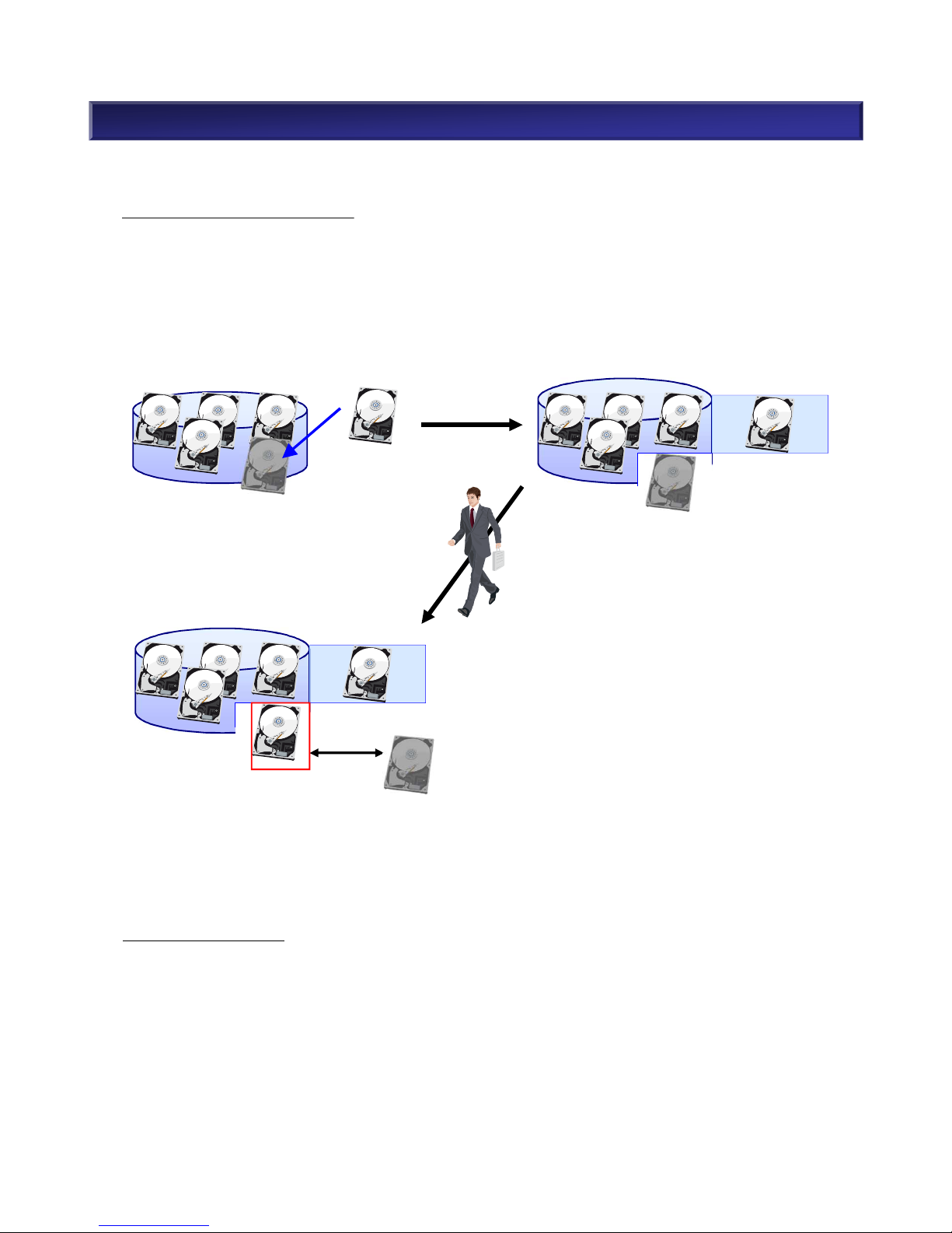
5. Functions <Hot Spare Disk (2)>
(2) Operation of Rebuilding Data to Hot Spare Disk
Copy Back Mode: Off (Default)
After the data is restored, the replaced disk is automatically designated as the hot spare disk. When
replacing the hot spare disk with the same capacity/rotation speed, data is not copied back. However,
when a hot spare disk with larger capacity/higher rotation speed is replaced with a disk drive of
smaller capacity/lower rotation speed, the data is copied back to its original location (on the replaced
disk).
Failure
5 x 15k SAS 300GB
RAID-5
Failure
Hot spare disk
15k SAS 300GB
Failed disk will be removed
from RAID and a hot spare disk
will become a member of RAID.
Failure
The disk that has replaced a
failed disk with will become
a new hot spare disk.
5 x 15k SAS 300GB
RAID-5
Replace
故障
Failure
15k SAS 300GB
New hot spare disk
Copy Back Mode: On
When replacing a failed disk with a new normal disk, and after the data restore has completed, data
on the hot spare disk is copied back to the new disk. When copy back mode is in progress,
scheduled maintenance (multi hot spare disk function) is not available. Refer to NEC
StorageManager for copy back mode setting.
60
NEC Confidential

(3) The Number of Hot Spare Disk Drive
• There is no upper limit for the number of hot spare disks.
• Bind hot spare disks when NL-SAS disk drives are in the system.
• Refer to the table below for the recommended numbers of hot spare disks for each type of disk
drive.
Recommended number of hot spare disk drives
Disk drive type Condition Recommendation
SAS Disk Drive
One type of capacity/rotation speed One hot spare drive / 24 disk drives
n types of capacity/rotation speed n spare disk drives / 24 disk drives
NL-SAS Disk Drive
*1
One type of capacity/rotation speed One hot spare drive / 12 disk drives
n types of capacity/rotation speed n spare disk drives / 12 disk drives
SAS SSD
Hot spare is optional. Because SAS SSD does not have mechanical parts
such as motors, heads and media, it is reliable. Therefore, hot spare is not
necessary.
5. Functions <Hot Spare Disk (3)>
*1
Must assign hot spare disks when NL-SAS disk drives are in the system.
61
NEC Confidential

5. Functions <Storage System Information Retention Function>
MV RV
1. Replication Reserved Volume
Difference
Shutdown
Only the difference
is copied from MV
to RV at reboot
Replication
Reserved
Volume
MV RV
2. No Replication Reserved Volume
Difference
Shutdown
Full copy of MV
to RV at rebootà
Increase I/O load
No differential
map of data
Storage System Information Retention Function
When using the data replication function, the storage system data such as the differential map between
the master volume (MV) and the replication volumes (RV) is created in the cache memory. The storage
system information retention function backs up the storage system data to a disk drive. The volume to
backup, which is called “replication reserved volume”, can be configured by the procedures in the NEC
StorageManager manual.
It is strongly recommended to use the storage system information retention function when using data
replication function. When not using the storage system information retention function, the updated
difference data is not saved when rebooting after the scheduled plan is completed, and requires a full
copy of data in MV to RV. Until copying of the entire data completes, an I/O load occurs which affects
the performance of operation. The replication reserved volume is 8.6GB (1GB=10003Byte) / 8.0GB
(1G=10243Byte).
Note:
Storage system information retention function is used for the planned stoppage to restore the storage
system information during the shutdown procedure but will not work for a power outage.
Manage differential
map of data
62
NEC Confidential

5. Functions <Automatic Online Firmware Update>
Automatic Online Firmware Update
M-Series firmware is compliant with ALUA. Firmware can be updated to the latest version without
stopping the system with the NEC Storage M-Series. The multipath environment with NEC Storage
PathManager or OS native multipath software is required in order to perform automatic online firmware
updates.
Firmware Firmware
63
NEC Confidential

5. Functions <Encryption Feature(1)>
(2) Supported SEDs
M-Series supports the following SED.
Model Interface Size
Rotation speed
(rpm)
Capacity
NF5322-SMA78LE SAS HDD 2.5” 15k 600GB
NF5322-SM768LE SAS HDD 2.5” 10k 600GB
NF5322-SM70ALE NL-SAS HDD 3.5” 7.2k 4TB
NF5322-SSAG5LE SAS SSD 2.5” - 200GB
NF5322-SSAR5LE SAS SSD 3.5” - 200GB
Encryption Feature
M-Series supports SED (Self Encryption Drive) as a hard drive encryption feature.
SED prevents access to data in case of stolen hard drives. SED has no adverse
impact on performance.
(1) SED type
• Encrypt data on the hard drive itself (media, cache)
• Protect against a data breach by hard drive theft
• Embedded encryption chip on the hard drive. No performance degradation with encryption.
64
NEC Confidential
(3) How to setup encryption
• When binding a pool with NEC StorageManager, see physical disk type. SED support/non-
support of hard disks is displayed.
• Encryption is enabled as encrypted hard drive’s default settings.
• After binding a pool, protect an encryption key within hard drives by modifying authentication
key using authentication key setting tool (CLI).

5. Functions <Encryption Feature(2)>
(4) Notes for encryption
• A disk array can consist of mix of encrypted hard drives (SED) and unencrypted hard drives
(non-SED).
• A pool cannot consist of mix which includes encrypted hard drives and unencrypted hard
drives. Bind hot spare disks for both encrypted hard drives and unencrypted hard drives.
• When data stored in SED is replicated to non-SED , the data replicated to non-SED HDD will
not be encrypted.
• When creating snapshot of data in SED, create SRA (Snapshot Reserved Area) in SED. If
SRA is created in non-SED, SV (Snapshot Volume) will not be encrypted.
• Do not apply SSD secondary cache for the logical disk by SED. The data in SSD secondary
cache is not be encrypted.
• A pool cannot be bound Immediately after unbinding a pool with SED HDDs. Wait a few
minutes, and then bind a pool. If it fails, wait another few minutes, then bind a pool. A logical
disk can be bound immediately after unbinding a logical disk.
65
NEC Confidential
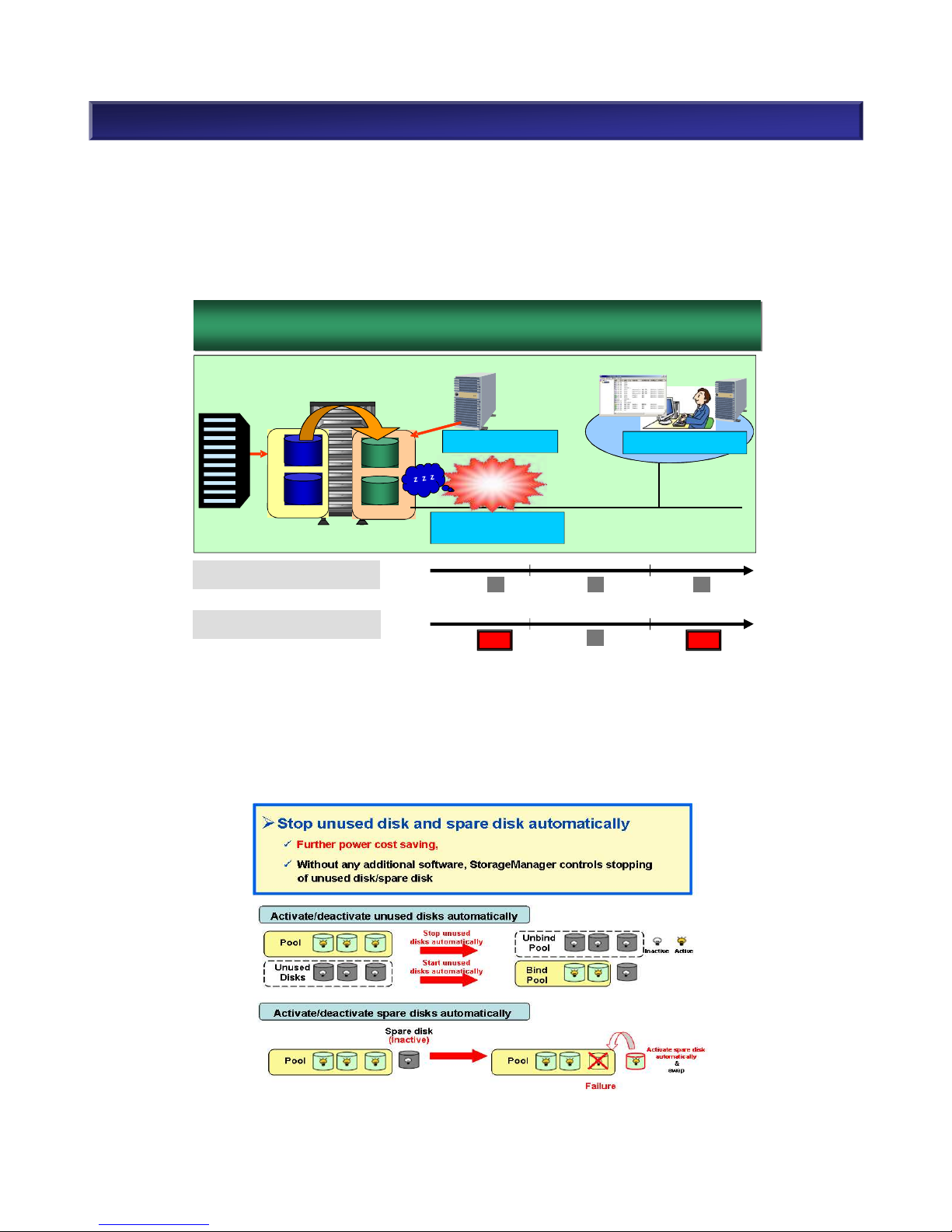
5. Functions <Power Saving Function (1)>
(1) Power Saving Function: MAID (Massive Array of Inactive Disks) Technology
Power Saving Function (MAID technology) reduces power consumption by turning off the motor power
of unused physical disk in backup volumes. The operation of disks, spare disks, and unassigned disks
in a pool can be controlled according to the status of volume usage which is specified by the logical
disks. By controlling the start/stop operation of the unused disks, the power function provides the
fundamental ability to support power saving operations in business.
StoragePowerConserver, which is bundled in M-Series Storage, can stop unused disks and hot spare
disks. Power saving function requires Storage Manager and Storage Control Command when
performing the following operations.
- Start/Stop volume usage
- Start/Stop pool operation
- Set power saving mode for each pool
n Example: M110 Configuration
66
MAID技術
~
Massive array of Inactive Disks
~
MAID Technology
Massive Array of Inactive Disks
Business
Server
DDR
M110
Backup Server
StorageManager Suite
Management
Server
Client
Storage Control Command
(Power Control)
StorageManager Express
Access Control
Storage Power Conserver
LAN
Business volume
Operating
Pool
Operating
Pool
Backup volume
Dormant
Pool
Copying
Pool
Reduce Power
Consumption
Max.30%
Existing : Power is always “ON”
for backup volume
Backup operation
Time
HDD motor
power supply
ON
MAID : Power is “ON” only at
operating backup
OFF
Backup operation
Time
OFF
ON
HDD motor
power supply
ON ON
NEC Confidential

5. Functions <VAAI Support (1)>
VAAI Support
(1) Server Virtualization
Typically server’s CPU utilization is low. To utilize the remaining resources, use server virtualization to
run multiple virtual machines on one physical server. There are many server virtualization software
products. VMware is one of the better known products and is widely used.
(2) Optimize Storage Performance
Vmware vSphere has VAAI (vStorage API for Array Integration) that optimizes storage performance.
M-Series supports the following three VAAI features.
• Full Copy
• Block Zeroing
• Hardware-Assisted Locking
Overview of these features can be found in the following pages.
(3) VAAI Support Settings
VAAI support settings can be configured by NEC StorageManager.
67
NEC Confidential

5. Functions <VAAI Support (2)>
n Full Copy
n Block Zeroing
Block zeroing is used in various scenarios. (For example, fill free disk space with zeros in order
to make virtual disk file optimal size.
2. VAAI Enabled
1. VAAI Disabled
VMware ESX
LINUX
Mail
Windows
Web
VM1 VM2
Windows
Web
VM3
Server writes zeros
VMware ESX
LINUX
Mail
Windows
Web
VM1 VM2
Windows
Web
VM3
Server offloads the block zeroing to the
storage.
Windows
Web
VM1
VM1 data
VM1.vmdk
Windows
Web
VM2
VM2 data
VM2.vmdk
Windows
Web
VM3
VM3 data
VM3.vmdk
Windows
Web
VM1
VM1 data
VM1.vmdk
Windows
Web
VM2
VM2 data
VM2.vmdk
Windows
Web
VM3
VM3 data
VM3.vmdk
Storage fills zeros in the area.
1. Copy Virtual Machine (VAAI disabled)
VMware ESX
LINUX
Mail
Windows
Web
VM1 VM2
Windows
Web
VM3
Server performs the copy
by reading and writing data
to the storage.
Server resources are used
to perform the copy.
Vmware ESX
LINUX
Mail
Windows
Web
VM1 VM2
Windows
Web
VM3
2. Copy Virtual Machine (VAAI enabled)
Windows
Web
VM3
Copy of
VM data
cpVM2.vmdk
Windows
Web
VM2
VM2 data
VM2.vmdk
Windows
Web
VM2
VM data
VM2.vmdk
Windows
Web
VM3
Copy of
VM data
cpVM2.vmdk
Server offloads the copy to the
storage. Copy is done within the
storage, which frees up resources
on the server.
68
NEC Confidential
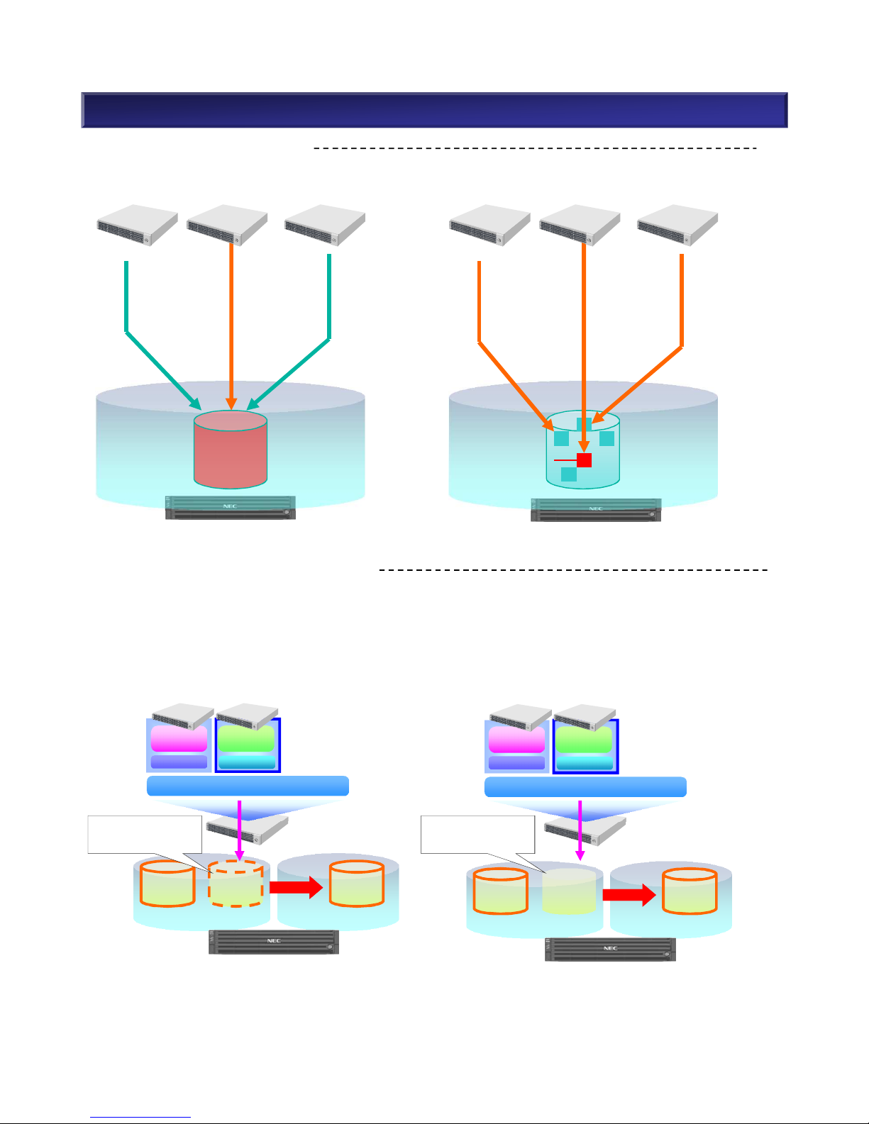
5. Functions <VAAI Support (3)>
n Hardware-Assisted Locking
1. Without Hardware-Assisted Locking
LOCK
2. With Hardware-Assisted Locking
Lock entire LUN.
Lock conflict occurs
often.
LOCK
× ×
n Thin Provisioning Space Reclamation
This example is with Storage vMotion. This function applies whenever removing/moving virtual
machines.
1. VAAI Disabled
VM1
VMDK
VMFS-A
VM2
VMDK
VM2
VMDK
VMware ESX
LINUX
Mail
Windows
Web
VM1 VM2
VMware ESX
LINUX
Mail
Windows
Web
VM1 VM2
2. VAAI Enabled
VMFS-B
Storage
vMotion
VM1
VMDK
VMFS-A
Freed
Area
VM2
VMDK
VMFS-B
Storage
vMotion
Move VM Move VM
Not freed Freed
This function enables ESX Server to monitor the space usage by virtual machines while
synchronizing with storage with thin provisioning. Previously when moving virtual machines, disk
space for virtual machines could not be freed. With the VAAI function, the disk space can be freed.
This makes it easier to operate/manage virtual machines in a thin provisioning environment.
Lock at block level.
Reduce lock conflicts
amongst servers.
69
NEC Confidential

5. Functions <Data Replication/Snapshot (1)>
Data Replication/Snapshot Consideration
(1) Data Replication
When using Data Replication (only), the maximum capacity of replication volume (RV) is as follows.
Model Total capacity of
dynamic pool
Max. capacity of
RV/MV
Total capacity of RVMax. generation of
RV
(DDR)
M110
~ Max. Capacity
256TB 500TB(50TB) 3
M310
~ Max. Capacity
256TB 500TB(50TB) 3
In-box replication
(DynamicDataReplication
)
Inter-box replication
(RemoteDataReplication)
Model M110 M310 M110 M310
8Gb FC Host I/F ○ ○ ○ ○
16Gb FC Host I/F ○ ○ ○ ○
1Gb iSCSI Host I/F ○ ○ ○ ○
10Gb iSCSI(Copper) Host I/F ○ ○ ○ ○
10Gb iSCSI(Optical) Host I/F ○ ○ ○ ○
12Gb SAS Host I/F ○ - - -
Single Controller - - - -
Dual Controller ○ ○ ○ ○
NEC StorageManager Express
(Embedded)
○ - - -
NEC StorageManager
○ ○ ○ ○
■ Data Replication Type Support Matrix
○:Supported -:Not supported
70
NEC Confidential

5. Functions <Data Replication/Snapshot (2)>
(2) Snapshot
When using Snapshot (only), the maximum capacity of snapshot related volumes is as follows.
Model Total capacity of
dynamic pool
Max. size of LD for
snapshot
Sum of snapshot
related volumes
Max. generation
of snapshots
M110 ~ Max. Capacity 10TB 160TB 16
M310 ~ Max. Capacity 10TB 160TB 16
Snapshot (DynamicSnapVolume)
Model M110 M310
8Gb FC Host I/F ○ ○
16Gb FC Host I/F ○ ○
1Gb iSCSI Host I/F ○ ○
10Gb iSCSI(Copper) Host I/F ○ ○
10Gb iSCSI (Optical)Host I/F ○ ○
12Gb SAS Host I/F ○ -
Single Controller - -
Dual Controller ○ ○
NEC StorageManager Express(Embedded)
○ -
NEC StorageManager ○ ○
■ Snapshot Support Matrix
Sum of Snapshot Related Volumes
= Master Volume Capacity + Snapshot Volume Capacity + Snapshot Reserved Area Capacity
<Calculation Example>
Master Volume 2TB has 8 generations of snapshot volumes and the snapshot reserved area per generation is
20%.
Snapshot Reserved Area = 2TB x 20% x 8 = 3.2TB
Sum of Snapshot Related Volumes = 2TB + 16TB + 3.2TB = 21.2TB
○:Supported -:Not supported
Snapshot
#1
Snapshot
#2
Snapshot
#3
Snapshot
#8
Differentia
l Data
Master
2TB
2TB
2TB
2TB
2TB
16TB
Snapshot
Reserved
Area
Updated
Differential
3.2T
B
8 generations
71
NEC Confidential
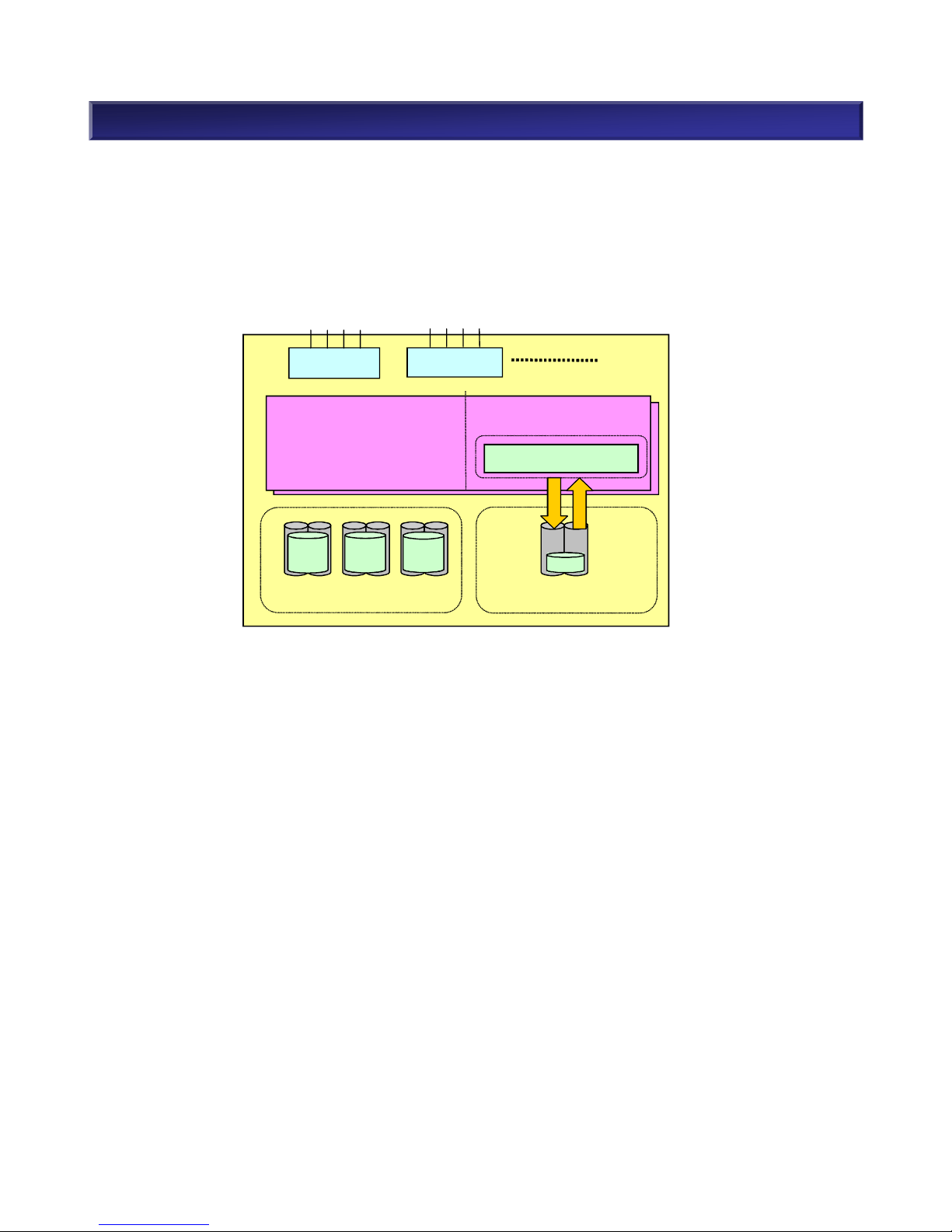
Note:
The control information area in cache memory is used for differential management information. When
the control information area overflows, it is no longer possible to store all pair information in it. In this
case the replication reserved volume is also used. Information which is less frequently accessed is
stored on this volume in order to store more pair differential management information. The system also
writes information in this volume and reads from it. Because of this physical disk access, overall
performance may be degraded.
5. Functions <Data Replication/Snapshot (3)>
Cache Memory
I/O Cache Area
Control Information Area
(Magnetic Disk) Logical Disk
Host Director
Host Director
Differential Management Info
Replication Reserved Volume
Write Read
72
NEC Confidential

5. Functions <UPS Considerations>
UPS Considerations
1. Select a UPS to meet both the apparent power (VA) and the active power (W) requirements of the
storage disk array unit. Refer to the UPS manual for more details.
2. Storage units have redundant power supplies, there are two AC inputs in each unit. Both power
supplies are in use during normal operation. In the event of one power supply should fail, due to a
tripped breaker off or UPS failure, the remaining power supply is capable of providing power. Make
sure that the selected UPS is capable of providing sufficient and reliable power for all devices.
UPS normal load
UPS2 failure
PS1 PS0
M310 (3.5”) Disk Array Controller
power consumption (NL-SAS)
252.5VA/250W 252.5VA/250W 505VA/500W
Disk Enclosure power consumption
(NL-SAS)
150VA/147.5W 150VA/147.5W 300VA/295W
UPS1 load power 402.5VA/397.5W -
805VA/795W
The active power
exceeds the UPS rating
level.
UPS2 load power - 402.5VA/397.5W (Fail)
3. When using a standby type UPS (requires a sensitivity mode setting) specific configuration
elements must be addressed. In order to ensure reliable power in the event of an outage, set the
sensitivity mode transfer time from the commercial power source to the battery power to 20ms or
less.
n Example: Improper configuration for active power
PS0
PS0
PS1
PS1
Rating:
750VA / 480W
UPS1
Disk Enclosure
(NL-SAS)
Rating:
750VA / 480W
Disk Array Controller
(NL-SAS)
UPS2
73
NEC Confidential
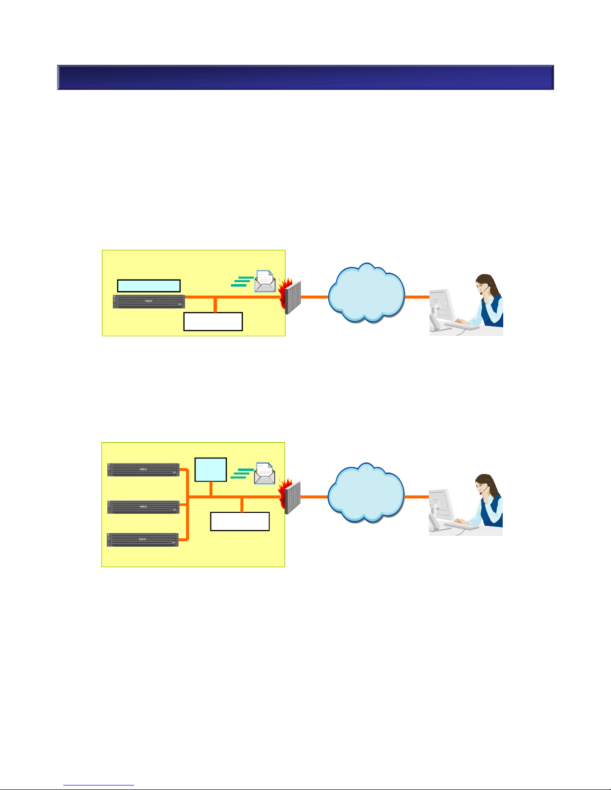
5. Functions < E-mail Notification Function >
E-mail Notification Function
In M-Series, when a hardware failure occurs, NEC StorageManager (SM) notifies the remote center of
the details about the failure via an e-mail.
Environment
The followings describe the configuration of the e-mail notification function.
1. E-mail notification from the storage unit (SM embedded)
Mail Server
Internet
Customer’s System
Remote Center
E-mail
EmbeddediSM
Storage
Mail Server
Customer’
s System
Remote Center
E-mail
Embedded iSM
2. E-mail notification from the storage units via iSM Server
NEC StorageManager is installed apart from the storage units. One NEC StorageManager
Server can notify a remote center of the events in multiple storage units.
Mail Server
The
Internet
Customer’s System
Remote Center
E-mail
iSM
Server
Storage
Storage
Storage
Mail Server
Internet
Customer’s System
Remote Center
E-mail
iSM
Server
Storage
Storage
Storage
NEC StorageManager is embedded in a storage unit.
74
NEC Confidential

5. Functions <PerforCache (1)>
PerforCache
PerforCache function improves disk array response by using SSDs (Solid State Drive) as second
cache. It reduces HDD (Hard Disk Drive) access associated with cache miss. The advantages to use
this function are:
• Response performance improvement
Even when cache miss occurs due to temporary high load, access will succeed to second cache.
This prevents performance response impairment that is caused by HDD access.
• Operation cost reduction
It is possible to improve performance by using SSDs while reducing electricity consumption
substantially over standard HDDs.
write read
2ndCache
SSD
HDD HDD HDD
write read
Pool
Disk Array
Business Servers
Cache
Module
Logical Disks
Cache
Controller Controller
Cache
PerforCache Features
Second cache is used for the following purposes:
• Read Cache
Store frequently accessed data in second cache. Provide data from second cache rather than from
HDDs when the same data is requested to be read.
• Write Cache
Improve write request response time. When there are many write requests at the same time, move
data from cache modules to second cache instead of writing data on cache modules to HDDs.
• Persistent Write
When controller is degraded, normally it will default to write-through mode to ensure data integrity.
As a result write request response will decline. Using second cache as replacement of cache in a
degraded controller prevents write request response degradation.
75
NEC Confidential

5. Functions <PerforCache (2)>
[Note]
Arrangement
• Arrange one set of PerforCache per disk array.
SSD
• When installing PerforCache, at least one SSD is required per disk array.
• When configuring second cache, select one from the following two types: read cache dedicated
or read cache/write cache/persistent write (multiple purpose).
§ Read cache dedicated: one or two SSDs per disk array.
§ Read cache/write cache/persistent write: two or four SDDs per disk array.
Installation/Configuration Considerations
• It is possible to install PerforCache later on a pre-existing storage array that was initially
configured without PerforCache .
• When configuring second cache, it is possible to use spare SSDs which were used for another
purpose. For example, unbind pool and re-configure as second cache.
76
NEC Confidential

Product Lifetime
The wear/lifetime of the product is defined for the hardware stable operation in M-Series. When
purchasing NEC products, it is recommended to review the wear/lifetime specifications and
replacement costs. Note that It may be necessary to replace components for stable operation prior to
the following lifetime depending on components..
5. Functions < Product Lifetime>
Lifetime of
Regular Replacement Component
Disk Array Unit, HDD, SAS SSD: 5 years
Lifetime of Consumables Battery: 5 years
Battery Replacement
The NEC Disk Array Unit performance is enhanced when write-cache is on. The battery power is used
to retain the data on cache when an unplanned disconnection such as a power outage occurs. The
battery power is consumed while the disk array is running. It is necessary to replace the battery in
about 5 years*. This replacement can be done while the system is running.
* The lifetime of the battery is shortened when it is used at high temperature. Whereas it is about five
years at an ambient temperature of 25ºC (77ºF), it decreases to about half (two years and six
months) when the ambient temperature rises 10ºC (18ºF). As the frequency of battery backup
increases, the lifetime of battery decreases. This lifetime above is calculated considering only an
unplanned power disconnection such as power outage.
Regular Replacement
The hard disk drive and fan for power supply has mechanicals parts(wearing parts). If over 7 years
operation is requested, regular replacement is needed at 5 years after operation is started. 5-year
regular replacement is only one time in the whole product lifetime.
As for Nearline SAS HDD and SAS SSD, regular replacement at 5 years is strongly recommended.
77
NEC Confidential
 Loading...