

Page 1
User's Manual
Video Distributor
LED-VD1
Page 2

Index
Declaration of conformity .......................................................................................................................... English-1
Important Information ................................................................................................................................ English-2
Safety Precautions, Maintenance & Recommended Use .......................................................................English-3
Contents ...................................................................................................................................................... English-4
Parts Name and Functions ........................................................................................................................ English-5
Front Panel .............................................................................................................................................. English-5
Rear panel ............................................................................................................................................... English-5
Connections ...............................................................................................................................................English-6
Connecting an External Device ............................................................................................................... English-6
Connecting the Power ............................................................................................................................. English-6
Connection Methods .................................................................................................................................. English-7
Installing Drivers ........................................................................................................................................English-8
Troubleshooting ....................................................................................................................................... English-10
Appendix ................................................................................................................................................... English-11
Specifications .........................................................................................................................................English-11
Pin Assignment (RS-485) .......................................................................................................................English-11
Communications Protocol .......................................................................................................................English-11
Dimensional Drawing ............................................................................................................................. English-12
Manufacturer’s Recycling and Energy Information ...............................................................................English-13
Page 3

Declaration of conformity
For USA
FCC Information
1. Use the attached specified cables with the LED-VD1 (D000LD) video distributor so as not to interfere with radio and television
reception.
(1) Please use the supplied power cord or equivalent to ensure FCC compliance.
(2) Please use a good quality shielded video signal cable.
Use of other cables and adapters may cause interference with radio and television reception.
2. This equipment has been tested and found to comply with the limits for a class A digital device, pursuant to Part 15 of the FCC
Rules. These limits are designed to provide reasonable protection against harmful interference when the equipment is operated
in a commercial environment. This equipment generates, uses, and can radiate radio frequency energy and, if not installed and
used in accordance with the instruction manual, may cause harmful interference to radio communications.
Operation of this equipment in a residential area is likely to cause harmful interference in which case the user will be required to
correct the interference at his own expense.
If necessary, the user should contact the dealer or an experienced radio/television technician for additional suggestions.
The user may find the following booklet, prepared by the Federal Communications Commission, helpful: “How to Identify and
Resolve Radio-TV Interference Problems.” This booklet is available from the U.S. Government Printing Office, Washington, D.C.,
20402, Stock No. 004-000-00345-4.
For Canada
Canadian Department of Communications Compliance Statement
DOC: This Class A digital apparatus meets all requirements of the Canadian Interference-Causing Equipment Regulations.
C-UL: Bears the C-UL Mark and is in compliance with Canadian Safety Regulations according to CAN/CSA C22.2 No. 60950-1.
Windows is a registered trademark of Microsoft Corporation.
English-1
Page 4
Important Information
WARNING
TO PREVENT FIRE OR SHOCK HAZARDS, DO NOT EXPOSE THIS UNIT TO RAIN OR MOISTURE. ALSO, DO NOT USE
THIS UNIT’S POLARIZED PLUG WITH AN EXTENSION CORD RECEPTACLE OR OTHER OUTLETS UNLESS THE PRONGS
CAN BE FULLY INSERTED.
REFRAIN FROM OPENING THE CABINET AS THERE ARE HIGH VOLTAGE COMPONENTS INSIDE.
REFER SERVICING TO QUALIFIED SERVICE PERSONNEL.
CAUTION
CAUTION:
TO REDUCE THE RISK OF ELECTRIC SHOCK, MAKE SURE POWER CORD IS UNPLUGGED FROM WALL
SOCKET. TO FULLY DISENGAGE THE POWER TO THE UNIT, PLEASE DISCONNECT THE POWER CORD
FROM THE AC OUTLET. DO NOT REMOVE COVER (OR BACK). NO USER SERVICEABLE PARTS INSIDE.
REFER SERVICING TO QUALIFIED SERVICE PERSONNEL.
This symbol warns user that uninsulated voltage within the unit may have sufficient magnitude to cause electric
shock. Therefore, it is dangerous to make any kind of contact with any part inside this unit.
This symbol alerts the user that important literature concerning the operation and maintenance of this unit has
been included. Therefore, it should be read carefully in order to avoid any problems.
CAUTION:
with this equipment, please contact your supplier. For all other cases, please use a power cord that matches the AC voltage of the
power outlet and has been approved by and complies with the safety standard of your particular country.
* When operating the video distributor LED-VD1 (D000LD) with its AC 125-240V power supply, use a power supply cord
that matches the power supply voltage of the AC power outlet being used.
NOTE:
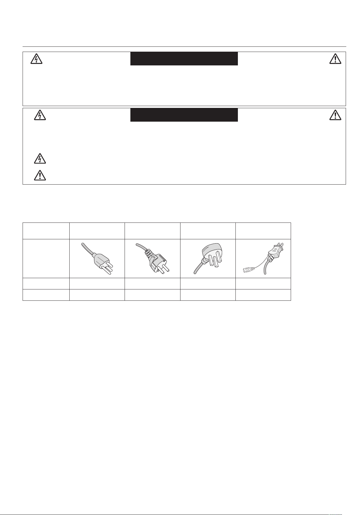
Please use the power cord provided with this display in accordance with the table below. If a power cord is not supplied
Plug type North America
Plug shape
Region U.S.A./Canada EU (except U.K.) U.K. Japan
Voltage 120* 230 230 100
This product can only be serviced in the country where it was purchased.
European
Continental
U.K. Japanese
English-2
Page 5

Safety Precautions, Maintenance & Recommended Use
FOR OPTIMUM PERFORMANCE, PLEASE NOTE THE FOLLOWING
WHEN SETTING UP AND USING
THE VIDEO DISTRIBUTOR:
DO NOT OPEN THE VIDEO DISTRIBUTOR.
•
serviceable parts inside and opening or removing covers may
expose you to dangerous shock hazards or other risks.
Refer all servicing to qualified service personnel.
• Do not spill any liquids into the cabinet or use your video distributor
near water.
• Do not insert objects of any kind into the cabinet slots, as they may
touch dangerous voltage points, which can be harmful or fatal or
may cause electric shock, fire or equipment failure.
• Do not place any heavy objects on the power cord.
Damage to the cord may cause shock or fire.
• Do not place this product on a sloping or unstable cart, stand or
table, as the video distributor may fall, causing serious damage to
the video distributor.
• The power supply cord you use must have been approved by and
comply with the safety standards of your country.
(Type H05VV-F 3G 1mm
• In UK, use a BS-approved power cord with molded plug having a
black (13A) fuse installed for use with this video distributor.
• Do not place any objects onto the video distributor and do not use
the video distributor outdoors.
• Do not bend, crimp or otherwise damage the power cord.
• If video distributor is broken, handle with care.
• Do not cover vent on video distributor.
• Do not use video distributor in high temperature, humid, dusty, or
oily areas.
• Allow adequate ventilation around the video distributor, so that heat
can properly dissipate. Do not block ventilated openings or place
the video distributor near a radiator or other heat sources.
Do not put anything on top of the video distributor.
• The power cable connector is the primary means of detaching
the system from the power supply. The video distributor should be
installed close to a power outlet, which is easily accessible.
• Do not move or mount this product by hanging a rope or wire to the
backside handle.
Do not mount or secure this product by using the backside handle.
It may fall and cause personal injury.
• Handle with care when transporting. Save packaging for
transporting.
• Please clean the holes of back cabinet to reject dirt and dust at
least once a year because of set reliability.
• It’s recommended to wipe holes a minimum of once a month.
2
should be used in Europe)
There are no user
Immediately unplug your video distributor from the wall outlet and refer
servicing to qualified service personnel under the following conditions:
• If the video distributor has an unusual odor.
• When the power supply cord or plug is damaged.
• If liquid has been spilled, or objects have fallen into the video
distributor.
• If the video distributor has been exposed to rain or water.
• If the video distributor has been dropped or the cabinet damaged.
• If the video distributor does not operate normally by following
operating instructions.
Cleaning the Cabinet
• Unplug the power supply
• Gently wipe the cabinet with a soft cloth
• To clean the cabinet, dampen the cloth with a neutral detergent and
water, wipe the cabinet and follow with a dry cloth.
NOTE:
DO NOT clean with benzene thinner, alkaline detergent,
alcoholic system detergent, glass cleaner, wax, polish cleaner,
soap powder, or insecticide. Rubber or vinyl should not be in
contact with the cabinet for an extended period of time. These
types of fluids and
or peel.
materials can cause the paint to deteriorate, crack
English-3
Page 6

Contents
The parts supplied with this unit are as follows.
In the rare case that one of these parts is missing or damaged, contact the retailer.
• Power cord (1.8 m US)
• Power cord (1.8 m EU)
• Signal cable (DVI-D, 1.8 m)
• USB/RS-485 adapter
• LAN cable (3 m)
• Utility disk
• Setup manual
A signal cable to connect the Video Distributor and LED Module is not included.
Compatible Signal Cable Specifications
- DVI-D dual link (max 30 meters: Signal quality may degrade depending on the quality of the signal cable)
English-4
Page 7

Parts Name and Functions
Front Panel
POWER LED DISPLAY OU TPUT DVI
1 2 3 4 5 6 7 8
POWER
1 2 3 4 5 6 7 8 OU T IN RS- 4 85
1 2 3 4 5
Power lamp
1
Lights up (red) when the power is ON.
LED Display lamp
2
The port connected to the LED module lights up (green).
DVI Output lamp
3
The port connected to the DVI input device lights up (orange).
Rear panel
OUT IN RS- 4 85
LED DISPLAY OUTPUT
LED-VD1 VI DEO D ISTR IBUTO R
DV I
DVI Input lamp
4
Lights up (orange) with an image signal is input to the DVI input terminal.
RS-485 lamp
5
Lights up (orange) when a command is sent or received.
1 2 4 5
8 7 6
Power Input Connector
1
Plug in the power cord here.
Power Switch
2
Turns ON or OFF the power. This device has no standby function.
Cooling Fan Vent
3
Vent for the cooling fan. Do not cover the ventilation.
DVI Input
4
The DVI input terminal. Connect a digital output device here.
DVI Output
5
The DVI output terminal. This is used when connecting this device in a cascaded
connection.
3
DVI Output (for LED Module)
6
DVI output for the LED module. Connect to the LED module's DVI input terminal
with a dual-link DVI cable.
Control Input/Output (RJ-45)
7
The control input/output terminal. Connect a LAN cable here using the included
RS-485 adapter.
Control Input/Output (RJ-45)
8
The control input/output terminal. This is used when connecting this
device in a cascaded connection. Do not connect the control input/output
terminal or USB/RS-485 adapter's RJ-45 for this device to a network
environment.
English-5
Page 8

Connections
Connecting an External Device
• To protect the device, switch off the power before connecting it.
• When connecting devices, follow the instructions in their user manuals.
Connecting the Power
NOTE :
• Connect the power cord to the unit before connecting it to the power outlet.
1. Insert one end of the power cord into the unit’s power input connector.
Insert the cord fully and securely.
2. Connect the power plug to a commercial power source outlet.
WARNING
• Do not use with a power voltage other than the indicated voltage. Doing so may cause a fire or electric shock.
• Use a power cord appropriate for your region if the power cord included is not compatible with your region.
• If the power cord has a ground wire, always be sure to ground it. When disconnecting the ground, be sure to disconnect the power plug from the outlet before
removing the ground. Also, make sure that the ground wire of the power plug does not enter or touch the power outlet. Otherwise, a fire or electric shock may result.
• The power cord supplied with the unit is for use with this product only. To ensure safety, do not use it with other devices.
NOTE :
• This socket-outlet shall be installed the equipment and shall be easily accessible.
English-6
Page 9

Connection Methods
Before Connecting
• Before connecting to the device, turn off the power to the device you are connecting to and all peripheral devices.
• Refer to the user's manuals for those devices.
Video processor
[LED-VP1]
LED module
Computer
(USB/RS485 adapter)
LED module
[LED-06AF1/LED-15BF1]
English-7
Page 10

Installing Drivers
1. Compatible Operating Systems
Windows 2000 Professional
Windows XP Professional
Windows 2003 Server
Windows Vista
Windows 7
2. How to Install
Connect the USB/RS-485 adapter to your PC after the drivers have successfully been installed.
Insert the included CD-ROM into your computer's optical media drive.
Run “RS485_SETUP.exe” in the “\Software\Driver” folder on the CD-ROM to begin the installation.
(1) Click [Next]. (2) View the terms of the license agreement, and if you agree, select "I
accept the terms of the license agreement" and click [Next].
(3) Click [Next]. (4) Click [Install].
(5) Check the box beside "Launch the CP210x VCP Driver Installer." and
click [Finish].
English-8
Page 11

(6) Click [Install].
(7) The Success window will be displayed. [OK] Click to complete the driver installation.
English-9
Page 12

Troubleshooting
Check the following items.
Problems/Symptoms Cause and Solution
Cannot perform LED module mapping
Cannot perform command communication • The USB/RS-485 adapter will be detected as a COM port by the PC. Check the COM port number of the connected
No image signal is displayed The image signal is only compatible with 1024x768 @60Hz. Check the resolution of the input signal.
The DVI Input Light is flashing If the resolution of the signal being input to the DVI input terminal is anything other than 1024x768, this light
The LED module connector cable for this product must be connected using a DVI dual-link cable.
adapter.
• The 4th and 5th pins of the RJ-45 cable are used for communication. Check to ensure that the 4th and 5th pins of
your LAN cable are connected properly.
• Be sure to only use a straight-type LAN cable. Check to ensure that you are not using a crossover LAN cable.
will flash.
Use an input signal with a resolution of 1024x768 @60Hz.
English-10
Page 13

Appendix
Specifications
Product Name LED-VD1 Notes
Interface
Image Input
Image Output
Control
Power Supply 100 to 240 VAC, 50/60 Hz
Power Consumption 15 W
Complied Regulatory and Guidelines cTUVus, TUV-GS, FCC(Class-A), CE(Class-A)
Dimension 480 (W) x 98 (H) x 325 (D) mm
Weight 4.6kg(10.1lbs)
Operating
Environment
Storage Environment
*1: Up to 8 LED-VD1s can be connected in a cascaded connection.
*2: Up to 25 LED modules can be connected in a cascaded connection.
*3: Include USB/RS-485 adapter. Use any commercially available LAN cable (category 5 straight-type: maximum 100 m in length).
NOTE: Technical specifications are subject to change without notice.
Compatible
Resolutions
Interface
Interface
Specifications RS-485
Temperature -20˚C to 40˚C
Humidity 10% to 90% (without condensation)
Temperature -30˚C to 60˚C
Humidity 10% to 90% (without condensation)
DVI-D
1024x768 @60Hz
(*1)
DVI-D
(*2)
DVI-D
(8 outputs)
(*3)
RJ-45
(input/output 1 system)
For cascade connection of LED-VD1
Connect to the LED module using a dual-link
cable
Pin Assignment (RS-485)
Pin No. Signal Name
1 Not connected
2 Not connected
3 Not connected
4 DATA -
5 DATA +
6 Not connected
7 Not connected
8 Not connected
Communications Protocol
Baud Rate 38400 bps
Data Bit 8 bit
Parity None
Stop Bit 1 bit
Flow Control None
18
English-11
Page 14

Dimensional Drawing
407
290.5
479.2
280
325.1
90
98.2
86.1
10.3
Unit: mm
English-12
Page 15

Manufacturer’s Recycling and Energy Information
NEC DISPLAY SOLUTIONS is strongly committed to environmental protection and sees recycling as one of the company’s top
priorities in trying to minimize the burden placed on the environment. We are engaged in developing environmentallyfriendly
products, and always strive to help define and comply with the latest independent standards from agencies such as ISO (International
Organisation for Standardization) and TCO (Swedish Trades Union).
Disposing of your old NEC product
The aim of recycling is to gain an environmental benefit by means of re-use, upgrading, reconditioning or reclamation of material.
Dedicated recycling sites ensure that environmentally harmful components are properly handled and securely disposed. To ensure
the best recycling of our products,
to handle the product in an environmentally sensitive way, once it has reached the end of its life.
All required information concerning the disposal of the product and country-specific information on recycling facilities can be found
on our following websites:
http://www.nec-display-solutions.com/greencompany/
http://www.nec-display.com
http://www.necdisplay.com
WEEE Mark (European Directive 2002/96/EC)
NEC DISPLAY SOLUTIONS offers a variety of recycling procedures
(in Europe),
(in Japan) or
(in USA).
and gives advice on how
Within the European Union
EU-wide legislation, as implemented in each Member State, requires that waste electrical and electronic
products carrying the mark (left) must be disposed of separately from normal household waste. This includes
monitors and electrical accessories, such as signal cables or power cords. When you need to dispose of your
NEC display products, please follow the guidance of your local authority, or ask the shop where you
purchased the product, or if applicable, follow any agreements made between yourself and NEC.
The mark on electrical and electronic products only applies to the current European Union Member States.
Outside the European Union
If you wish to dispose of used electrical and electronic products outside the European Union, please contact your local
authority so as to comply with the correct disposal method.
English-13
 Loading...