


IP8800/S6700, IP8800/S6600, IP8800/S6300, IP8800/S3600,
IP8800/S2400
Troubleshooting Guide
IP88S36-T001-000
Thoroughly read and store this manual.
• Read and thoroughly understand safety-related explanations before using this product.
• Keep this manual in a location close at hand for easy reference.

■ Applicable products
This manual describes models IP8800/S6700, IP8800/S6600, IP8800/S6300, IP8800/S3600, and IP8800/S2400 series.
■ Caution when exporting
The necessary procedures are to be adopted when exporting this product after first confirming the regulations of the Foreign Exchange and
Foreign Trade Law, U.S. export control related regulations, etc.
If any questions remains, please consult with our sales department.
■ Trademarks
Cisco is a registered trademark of U.S. Cisco Systems, Inc. in the U.S. and other countries.
Ethernet is a product name of Xerox Corp. in the U.S.
GSRP is a registered trademark of ALAXALA Networks Corporation.
Internet Explorer is a trademark or registered trademark of Microsoft Corporation in the U.S. and other countries.
IPX is a trademark of Novell, Inc.
Microsoft is a registered trademark of Microsoft Corp. in the U.S. and other countries.
RSA and RSA SecurID are trademarks or registered trademarks of RSA Security Inc. in the U.S. and other countries.
sFlow is a registered trademark of InMon Corp. in the U.S. and other countries.
UNIX is a registered trademark in the U.S. and other countries exclusively licensed by X/Open Company Limited.
VitalQIP and VitalQIP Registration Manager are trademarks of Lucent Technologies.
VLANaccessClient is a trademark of NEC Software.
Windows is a registered trademark of Microsoft Corp. in the U.S. and other countries.
Other company names and product names are trademarks or registered trademarks of their respective companies.
■ Thoroughly read and store this manual
Read and thoroughly understand safety-related explanations before using this product.
Keep this manual in a location close at hand for easy reference.
■ Note
The contents of this manual may be modified at any time for improvement without notice.
Note that output display examples and figures may be different from the actual states.
Issue date
November, 2009 (1st Edition) IP88S36-T001-000
■ Copyright
Copyright (c) 2009, NEC Corporation, All rights reserved.

Introduction
■ Applicable product
This manual describes models IP8800/S6700, IP8800/S6600, IP8800/S6300, IP8800/S3600 and IP8800/S2400.
Please read the manual carefully and thoroughly understand the instructions and cautions contained herein before operating the
device. Keep the manual in a location close at hand for easy reference when necessary.
Unless otherwise specified, this manual describes functions common to the models. The mark below refers to functions specific
to respective models.
[IP8800/S6700]:
The description is applicable to IP8800/S6700.
[IP8800/S6600]:
The description is applicable to IP8800/S6600.
[IP8800/S6300]:
The description is applicable to IP8800/S6300.
[IP8800/S3600]:
The description is applicable to IP8800/S3600.
[IP8800/S2400]:
The description is applicable to IP8800/S2400.
If more than one mark is indicated such as [IP8800/S3600] [IP8800/S2400], the function is only supported by those two
models or the description is not applicable to other models.
The mark below refers to functions supported by option licenses.
[OP-NPAR]:
The description is applicable to option license OP-NPAR.
[OP-OPT]:
The description is applicable to option license OP-OTP.
[OP-VAA]:
The description is applicable to option license OP-VAA.
■ Correction of this manual
Contents in this manual may be corrected in the "Release note" or "manual correction document" provided with software.
■ Intended users
This manual has been written for system managers who develop and operate network systems using IP8800/S6700, IP8800/
S6600, IP8800/S6300, IP8800/S3600, or IP8800/S2400.
In addition, an understanding of the following is assumed.
• Basic knowledge of network system management
■ Manual referred to
Manuals to be referenced according to the flow of tasks from installation and setup to daily operations are indicated below.
I
Introduction
Procedures from unpacking the product
to making basic settings at the initial
installation
IP8800/S6700
Quick Start Guide (IP88S67-Q001)
IP8800/S6600
Quick Start Guide (IP88S66-Q001)
IP8800/S6300
Quick Start Guide (IP88S63-Q001)
Information on the facility requirement of
the hardware
IP8800/S6700
Hardware lnstallation Guide (IP88S67-H001)
Information on handling of the hardware IP8800/S6600
Hardware lnstallation Guide (IP88S66-H001)
IP8800/S6300
Hardware lnstallation Guide (IP88S63-H001)
Information on software functions,
configuration, and confirmation by using
operation commands
IP8800/S6300 Software Manual
Configuration Settings, Vol.1 (IP88S63-S001)
IP8800/S6300 Software Manual
Configuration Settings, Vol.2 (IP88S63-S002)
IP8800/S6300 Software Manual
Configuration Settings, Vol.3 (IP88S63-S003)
Syntax and parameter details of
configuration commands
IP8800/S6300 Software Manual
Configuration Commands, Vol.1 (IP88S63-S004)
IP8800/S6300 Software Manual
Configuration Commands, Vol.2 (IP88S63-S005)
Syntax and parameter details of
operation commands
IP8800/S6300 Software Manual
Operation Commands, Vol.1 (IP88S63-S006)
IP8800/S6300 Software Manual
Operation Commands, Vol.2 (IP88S63-S007)
Details of operation messages and logs IP8800/S6300 Software Manual
Message Log Reference (IP88S63-S008)
Details of supported MIBs IP8800/S6300 Software Manual
MIB Reference (IP88S63-S009)
lnformation on troubleshooting IP8800/S6700, IP8800/S6600, IP8800/S6300,
IP8800/S3600, IP8800/S2400
Troubleshooting Guide (IP88S36-T001)
For IP8800/S6700, IP8800/S6600, and IP8800/S6300
II
For IP8800/S3600
Procedures from unpacking the product
to making basic settings at the initial
installation
IP8800/S3600, IP8800/S2400
Quick Start Guide (IP88S36-Q001)
Information on the facility requirement of
the hardware
IP8800/S3600, IP8800/S2400
Hardware lnstallation Guide (IP88S36-H001)
Information on handling of the hardware
Information on software functions,
configuration, and confirmation by using
operation commands
IP8800/S3600 Software Manual
Configuration Settings, Vol.1 (IP88S36-S001)
IP8800/S3600 Software Manual
Configuration Settings, Vol.2 (IP88S36-S002)
IP8800/S3600 Software Manual
Configuration Settings, Vol.3 (IP88S36-S003)
Syntax and parameter details of
configuration commands
IP8800/S3600 Software Manual
Configuration Commands, Vol.1 (IP88S36-S004)
IP8800/S3600 Software Manual
Configuration Commands, Vol.2 (IP88S36-S005)
Syntax and parameter details of
operation commands
IP8800/S3600 Software Manual
Operation Commands, Vol.1 (IP88S36-S006)
IP8800/S3600 Software Manual
Operation Commands, Vol.2 (IP88S36-S007)
Details of operation messages and logs IP8800/S3600 Software Manual
Message Log Reference (IP88S36-S008)
Details of supported MIBs IP8800/S3600 Software Manual
MIB Reference (IP88S36-S009)
lnformation on troubleshooting IP8800/S6700, IP8800/S6600, IP8800/S6300,
IP8800/S3600, IP8800/S2400
Troubleshooting Guide (IP88S36-T001)
Introduction
III
Introduction
Procedures from unpacking the product
to making basic settings at the initial
installation
IP8800/S3600, IP8800/S2400
Quick Start Guide (IP88S36-Q001)
Information on the facility requirement of
the hardware
IP8800/S3600, IP8800/S2400
Hardware Installation Guide (IP88S36-H001)
Information on handling of the hardware
Information on software functions,
configuration, and confirmation by using
operation commands
IP8800/S2400 Software Manual
Configuration Settings, Vol.1 (IP88S24-S001)
IP8800/S2400 Software Manual
Configuration Settings, Vol.2 (IP88S24-S002)
Syntax and parameter details of
configuration commands
IP8800/S2400 Software Manual
Configuration Commands (IP88S24-S003)
Syntax and parameter details of
operation commands
IP8800/S2400 Software Manual
Operation Commands (IP88S24-S004)
Details of operation messages and logs IP8800/S2400 Software Manual
Message Log Reference (IP88S24-S005)
Details of supported MIBs IP8800/S2400 Software Manual
MIB Reference (IP88S24-S006)
Information on troubleshooting IP8800/S6700, IP8800/S6600, IP8800/S6300,
IP8800/S3600, IP8800/S2400
Troubleshooting Guide (IP88S36-T001)
For IP8800/S2400
■ Conventions: abbreviations
AC Alternating Current
ACK ACKnowledge
ADSL Asymmetric Digital Subscriber Line
ALG Application Level Gateway
ANSI American National Standards Institute
ARP Address Resolution Protocol
AS Autonomous System
AUX Auxiliary
BCU Basic Control Unit
BGP Border Gateway Protocol
BGP4 Border Gateway Protocol - version 4
BGP4+ Multiprotocol Extensions for Border Gateway
bit/s bits per second *Usually, abbreviated as bps.
BPDU Bridge Protocol Data Unit
BRI Basic Rate Interface
BSU Basic Switching Unit
CC Continuity Check
CDP Cisco Discovery Protocol
CFM Connectivity Fault Management
CIDR Classless Inter-Domain Routing
Protocol - version 4
IV

Introduction
CIR Committed Information Rate
CIST Common and Internal Spanning Tree
CLNP ConnectionLess Network Protocol
CLNS ConnectionLess Network System
CONS Connection Oriented Network System
CRC Cyclic Redundancy Check
CSMA/CD Carrier Sense Multiple Access with Collision
Detection
CSNP Complete Sequence Numbers PDU
CST Common Spanning Tree
CSU Control and Switching Unit
DA Destination Address
DC Direct Current
DCE Data Circuit terminating Equipment
DHCP Dynamic Host Configuration Protocol
DIS Draft International Standard/Designated
Intermediate System
DNS Domain Name System
DR Designated Router
DSAP Destination Service Access Point
DSCP Differentiated Services Code Point
DTE Data Terminal Equipment
DVMRP Distance Vector Multicast Routing Protocol
E-Mail Electronic Mail
EAP Extensible Authentication Protocol
EAPOL EAP Over LAN
EFM Ethernet in the First Mile
ES End System
FAN Fan Unit
FCS Frame Check Sequence
FDB Filtering DataBase
FQDN Fully Qualified Domain Name
FTTH Fiber To The Home
GBIC GigaBit Interface Converter
GSRP Gigabit Switch Redundancy Protocol
HMAC Keyed-Hashing for Message Authentication
IANA Internet Assigned Numbers Authority
ICMP Internet Control Message Protocol
ICMPv6 Internet Control Message Protocol version 6
ID Identifier
IEC International Electrotechnical Commission
IEEE Institute of Electrical and Electronics
Engineers, Inc.
IETF the Internet Engineering Task Force
IGMP Internet Group Management Protocol
IP Internet Protocol
IPCP IP Control Protocol
IPv4 Internet Protocol version 4
IPv6 Internet Protocol version 6
IPV6CP IP Version 6 Control Protocol
IPX Internetwork Packet Exchange
ISO International Organization for Standardization
ISP Internet Service Provider
IST Internal Spanning Tree
L2LD Layer 2 Loop Detection
LAN Local Area Network
LCP Link Control Protocol
LED Light Emitting Diode
LLC Logical Link Control
LLDP Link Layer Discovery Protocol
LLPQ Low Latency Priority Queueing
LLQ+3WFQ Low Latency Queueing + 3 Weighted Fair Queueing
LLRLQ Low Latency Rate Limited Queueing
LSP Label Switched Path
LSP Link State PDU
LSR Label Switched Router
MA Maintenance Association
MAC Media Access Control
MC Memory Card
MD5 Message Digest 5
MDI Medium Dependent Interface
MDI-X Medium Dependent Interface crossover
MEP Maintenance association End Point
MIB Management Information Base
V

Introduction
MIP Maintenance domain Intermediate Point
MRU Maximum Receive Unit
MSTI Multiple Spanning Tree Instance
MSTP Multiple Spanning Tree Protocol
MSU Management and Switching Unit
MTU Maximum Transfer Unit
NAK Not AcKnowledge
NAS Network Access Server
NAT Network Address Translation
NCP Network Control Protocol
NDP Neighbor Discovery Protocol
NET Network Entity Title
NIF Network Interface
NLA ID Next-Level Aggregation Identifier
NPDU Network Protocol Data Unit
NSAP Network Service Access Point
NSSA Not So Stubby Area
NTP Network Time Protocol
OADP Octpower Auto Discovery Protocol
OAM Operations,Administration,and Maintenance
OSPF Open Shortest Path First
OUI Organizationally Unique Identifier
PAD PADding
PAE Port Access Entity
PC Personal Computer
PCI Protocol Control Information
PDU Protocol Data Unit
PICS Protocol Implementation Conformance Statement
PID Protocol IDentifier
PIM Protocol Independent Multicast
PIM-DM Protocol Independent Multicast-Dense Mode
PIM-SM Protocol Independent Multicast-Sparse Mode
PIM-SSM Protocol Independent Multicast-Source Specific
Multicast
PoE Power over Ethernet
PRI Primary Rate Interface
PS Power Supply
PSNP Partial Sequence Numbers PDU
PSP Packet Switching Processor
QoS Quality of Service
RA Router Advertisement
RADIUS Remote Authentication Dial In User Service
RDI Remote Defect Indication
REJ REJect
RFC Request For Comments
RGQ Rate Guaranteed Queueing
RIP Routing Information Protocol
RIPng Routing Information Protocol next generation
RMON Remote Network Monitoring MIB
RPF Reverse Path Forwarding
RQ ReQuest
RSTP Rapid Spanning Tree Protocol
SA Source Address
SD Secure Digital
SDH Synchronous Digital Hierarchy
SDU Service Data Unit
SEL NSAP SELector
SFD Start Frame Delimiter
SFP Small Form factor Pluggable
SMTP Simple Mail Transfer Protocol
SNAP Sub-Network Access Protocol
SNMP Simple Network Management Protocol
SNP Sequence Numbers PDU
SNPA Subnetwork Point of Attachment
SOP System Operational Panel
SPF Shortest Path First
SSAP Source Service Access Point
STP Spanning Tree Protocol
TA Terminal Adapter
TACACS+ Terminal Access Controller Access Control System
Plus
TCP/IP Transmission Control Protocol/Internet Protocol
TLA ID Top-Level Aggregation Identifier
TLV Type, Length, and Value
VI

Introduction
TOS Type Of Service
TPID Tag Protocol Identifier
TTL Time To Live
UDLD Uni-Directional Link Detection
UDP User Datagram Protocol
UPC Usage Parameter Control
UPC-RED Usage Parameter Control - Random Early Detection
uRPF unicast Reverse Path Forwarding
VAA VLAN Access Agent
VLAN Virtual LAN
VPN Virtual Private Network
VRF Virtual Routing and Forwarding/Virtual Routing
VRRP Virtual Router Redundancy Protocol
WAN Wide Area Network
WDM Wavelength Division Multiplexing
WFQ Weighted Fair Queueing
WGQ Weighted Guaranteed Queueing
WRED Weighted Random Early Detection
WS Work Station
WWW World-Wide Web
XFP 10 gigabit small Form factor Pluggable
and Forwarding Instance
■ Conventions: kB, MB, GB, and TB
1 kB(kilobytes), 1 MB(megabytes), 1 GB(gigabytes), and 1 TB(terabytes) indicate 1024 bytes, 10242 bytes, 10243 bytes, and
4
bytes respectively.
1024
VII


Contents
Introduction I
Safety Guide [IP8800/S6700] v
Safety Guide [IP8800/S6600] xvii
Safety Guide [IP8800/S6300] xxix
Safety Guide [IP8800/S3600] [IP8800/S2400] xli
1 Overview 1
1.1 Failure Analysis Overview 2
1.2 System and Partial Failure Analysis Overview 3
1.2.1 Failure Analysis for IP8800/S6700, IP8800/S6600, and IP8800/S6300 3
1.2.2 Failure Analysis for IP8800/S3600 and IP8800/S2400 4
1.3 Functional Failure Analysis Overview 7
2 Troubleshooting System Failures 11
2.1 Troubleshooting for IP8800/S6700, IP8800/S6600, and IP8800/S6300 12
2.1.1 Troubleshooting Procedure on System Failures 12
2.1.2 Replacement Method of Optional Components 14
2.2 Troubleshooting for IP8800/S3600 and IP8800/S2400 15
2.2.1 Troubleshooting Procedure on System Failures 15
2.2.2 Isolating Failures on External Power Unit 17
2.2.3 Replacement Method of System and Optional Components 18
3 Troubleshooting Functional Failures in Operation 19
3.1 Problems on Login Password 21
3.1.1 Forgot the Login User Password 21
3.1.2 Forgot the System Administrator Password 21
3.2 Problems on MC 22
3.2.1 "MC:--------" is displayed by entering the show system command or the show mc command 22
3.2.2 "MC not found" is displayed when MC is accessed 22
3.3 Problems on Operation Terminal 23
3.3.1 Unable to Input/Display from the Console Correctly 23
3.3.2 Login from the Remote Operation Terminal Is Failed 24
3.3.3 Login Authentication Using RADIUS/TACACS+ Is Disabled 25
3.3.4 Command Authorization Using RADIUS/TACACS+ Is Disabled 25
i

Contents
3.4 Network Interface Communication Failure 27
3.4.1 Ethernet Port Cannot Be Connected 27
3.4.2 Communication Failure in Basic Switching Unit BSU/PSP 29
3.4.3 Actions against Troubles on 10BASE-T/100BASE-TX/1000BASE-T 30
3.4.4 Actions against Troubles on 1000BASE-X 32
3.4.5 Actions against Troubles on 10GBASE-R 33
3.4.6 Communication Failure on Using PoE 35
3.4.7 Communication Failure on Using Link Aggregation 36
3.5 Layer 2 Network Communication Failure 38
3.5.1 Layer 2 Communication by VLAN Is Disabled 38
3.5.2 Failures on Using Spanning Tree 40
3.5.3 Failures on Using Ring Protocol 41
3.5.4 Multicast Relay by IGMP snooping Is Disabled 44
3.5.5 Multicast Relay by MLD snooping Is Disabled 47
3.6 IPv4 Network Communication Failure 50
3.6.1 Communication Is Disabled or Is Disconnected 50
3.6.2 IP Addresses Cannot Be Assigned Using DHCP Function 54
3.6.3 DynamicDNS Cooperation in DHCP Function Is Disabled 58
3.7 IPv4 Unicast Routing Communication Failure 61
3.7.1 No RIP Routing Information Exists 61
3.7.2 No OSPF Routing Information Exists 61
3.7.3 No BGP4 Routing Information Exists 62
3.7.4 No Routing Information Exist [OP-NPAR] 62
3.8 IPv4 Multicast Routing Communication Failure 63
3.8.1 Communication on IPv4 PIM-SM Network Is Disabled 63
3.8.2 Multicast Data Is Double-relayed on IPv4 PIM-SM Network 66
3.8.3 Communication on IPv4 PIM-SSM Network Is Disabled 67
3.8.4 Multicast Data Is Double-relayed on IPv4 PIM-SSM Network 69
3.8.5 IPv4 Multicast Communication Failure In VRF [OP-NPAR] 70
3.9 IPv6 Network Communication Failure 71
3.9.1 Communication Is Disabled or Is Disconnected 71
3.9.2 IPv6 DHCP Troubleshooting 73
3.10 IPv6 Unicast Routing Communication Failure 79
3.10.1 No RIPng Routing Information Exists 79
3.10.2 No OSPFv3 Routing Information Exists 79
3.10.3 No BGP4+ Routing Information Exists 80
3.11 IPv6 Multicast Routing Communication Failure 81
3.11.1 Communication on IPv6 PIM-SM Network Is Disabled 81
3.11.2 Multicast Data Is Double-relayed on IPv6 PIM-SM Network 84
3.11.3 Communication on IPv6 PIM-SSM Network Is Disabled 85
3.11.4 Multicast Data Is Double-relayed on IPv6 PIM-SSM Network 87
3.12 Layer 2 Authentication Communication Failure 89
3.12.1 Communication Failure on Using IEEE 802.1X 89
3.12.2 Communication Failure on Using Web Authentication 92
3.12.3 Communication Failure on Using MAC Authentication 97
3.12.4 Communication Failure on Using Authentication VLAN [OP-VAA] 99
ii

Contents
3.13 Communication Failure on High-reliability Function 103
3.13.1 GSRP Communication Failures 103
3.13.2 Communication with VRRP Configuration in IPv4 Network Is Disabled 105
3.13.3 Communication with VRRP Configuration in IPv6 Network Is Disabled 107
3.14 SNMP Communication Failure 110
3.14.1 MIBs Cannot Be Obtained from SNMP Manager 110
3.14.2 Traps Cannot Be Received by SNMP Manager 110
3.15 Troubleshooting of sFlow Statistics (Flow Statistics) Function 112
3.15.1 sFlow Packets Do Not Reach Collector 112
3.15.2 Flow Sample Does Not Reach Collector 115
3.15.3 Counter Sample Does Not Reach Collector 115
3.16 Communication Failures on Neighboring System Managing Function 116
3.16.1 Unable to Obtain Neighboring System Information via LLDP Function 116
3.16.2 Unable to Obtain Neighboring System Information via OADP Function 116
3.17 NTP Communication Failure 118
3.17.1 Time Synchronization by NTP Is Disabled 118
3.18 Communication Failure on IEEE802.3ah/UDLD Function 119
3.18.1 Port Becomes Inactive Due to IEEE802.3ah/UDLD Function 119
3.19 Problems on Redundant Configuration of Basic Control Unit (BCU)/Control and Switching Unit (CSU)/
Management and Switching Unit (MSU) [IP8800/S6700] [IP8800/S6600] [IP8800/S6300] 120
3.19.1 Active System Switchover Is Disabled 120
3.20 Problems on Redundant Configuration of Basic Switching Unit (BSU) [IP8800/S6700] 121
3.20.1 Active BSU Switchover Is Disabled 121
3.21 Problems on Power Saving Feature 123
3.21.1 Schedule Is Disabled [IP8800/S6700] [IP8800/S6600] 123
3.22 Congestion Caused by Packets Processed Through CPU Is Not Recovered 124
3.23 Communication Failure Caused by Settings of Filtering/QoS 126
3.23.1 Checking Filtering/QoS Setting Information 126
4 Troubleshooting Communication Failures Due to Resource Shortage [IP8800/S6700]
[IP8800/S6600] [IP8800/S6300] 129
4.1 MAC Address Table Resource Shortage 130
4.1.1 Checking Resource Usage of MAC Address Table 130
4.1.2 Action to Be Taken When MAC Address Table Resource Shortage Occurs 130
4.2 When Resource Shortage of VLAN Identification Table Occurs 133
4.2.1 Checking VLAN Identification Table Resource Usage 133
4.2.2 Action to Be Taken When VLAN Identification Table Resource Shortage Occurs 133
4.3 When Resource Shortage Occurs in Shared Memory 135
4.3.1 Checking Resource Usage of Shared Memory 135
4.3.2 Action to Be Taken When Resource Shortage of Shared Memory Occurs 135
5 Collecting Failure Information 137
5.1 Collecting Failure Information 138
5.1.1 Collecting Failure Information Using ftp Command from the Operation Terminal 138
iii

Contents
5.1.2 Collecting Failure Information Using dump Command [IP8800/S6700] [IP8800/S6600]
[IP8800/S6300] 140
5.2 Transferring Files for Maintenance Information 144
5.2.1 Transferring Files Using ftp Command 145
5.2.2 Transferring Files Using zmodem Command [IP8800/S3600] [IP8800/S2400] 148
5.2.3 Transferring Maintenance Information Files Using show tech-support Command 148
5.2.4 Transferring Files Using ftp Command from the Operation Terminal 150
5.3 Writing to MC 152
5.3.1 Writing File to MC Using Operation Terminal 152
6 Line Test 153
6.1 Testing Line 154
6.1.1 Ethernet Port 154
7 Restarting the System 159
7.1 Restarting the System 160
7.1.1 Restarting the System 160
Appendix 165
Appendix A Contents of show tech-support Command Display 166
Appnedix A.1 Contents of show tech-support Command Display 166
Index 187
iv

Safety Guide [IP8800/S6700]
■ Safety guide for the IP8800/S6700 series
• This document provides safety-related notices for use of the IP8800/S6700 series. To utilize the functions
of this device, read this document completely and carefully before using the device.
• Keep this document at hand after you read it, so that you can always refer it later.
• For any operation, follow the directions and procedures given by this document.
• Observe the cautions labeled on the device or those presented by this document. If you fail to do so, you
will cause damage to yourself or the device.
■ Symbols
• We have various symbols displayed on the IP8800/S6700 series and in the manuals to guide you in using
the IP8800/S6700 series correctly and safely without injuring yourself and others, or damaging equipment
assets. Below are the symbols and their meanings. Fully understand the description and then proceed with
reading the main part of the manual.
If you ignore instructions preceded by this symbol, you could cause personal injury or
WARNING
death to yourself and others.
If you ignore instructions preceded by this symbol, you could cause personal injury to
CAUTION
CAUTION
NOTE
yourself and others, or serious damage to the device or surroundings.
If you ignore instructions preceded by this symbol, you could cause physical damage
to the device or surroundings.
A note is informational in nature. Unlike warning and caution notices, notes (for
prevention of malfunction, prevention of product minor damages) are not related to the
physical injury or damage to the device.
■ Operations and actions
• Do not attempt to perform any operations not specifically described in this document.
In case of a problem on the device, contact the maintenance personnel after performing the following.
• For the device with AC power supply mounted, power off the device and unplug the power cable from the outlet.
• For the device with DC power supply mounted, power off the device and turn off the breaker in the power supply
equipment.
■ Be careful in operation
• The instructions shown on the device or in this manual are the results of our thorough consideration.
However, an unexpected situation may occur. For operations, not only follow the instructions but also
always be careful with your judge.
v

Safety Guide [IP8800/S6700]
WARNING
■ In case a failure should occur, power off the device immediately.
• In case fume or unusual odor should occur, or foreign matters should come into the device, power off the
device as follows. If the device is used in a faulty state, fire disasters or electric shock may be caused.
• For the device with AC power supply mounted, power off the device and unplug the power cable from the
outlet.
• For the device with DC power supply mounted, power off the device and turn off the breaker in the power
supply equipment because the power cable is connected via a terminal.
■ Do not place the device in an unstable location.
• If the device is being placed on a table, be sure to install it horizontally on a workbench or the like that can
sufficiently bear the weight of the device. If the device is placed on an unstable location such on a shaky
table or slope, the device may fall and drop and consequently personal injury may occur.
■ Do not remove the device cover.
• Do not remove the device cover. Electric shock may be caused.
■ Do not put foreign matters in the device.
• Do not insert or drop metals or combustibles into the device through the intake/exhaust port. Fire disasters
or electric shock may be caused.
■ Modification is not permissible.
• Device modification is not permissible. Fire disasters or electric shock may be caused.
■ Do not give a shock.
• In case the device is dropped or parts are damaged, power off the device, pull the cable out of the outlet,
and call the maintenance engineer. Otherwise it can cause a fire or electric shock.
■ Do not put any material on the device.
• Do not put a metal such as pin or clip or a container with water in it such as vase or flower pot on the device.
Fire disasters or electric shock may be caused.
■ Do not use power not specified.
• Do not use a supply voltage not specified. Fire disasters or electric shock may be caused.
■ The current capacity supplied to the power distribution panel must be larger than the
operating current of the breaker.
• The current capacity supplied to the power distribution panel must be larger than the operating current of
the breaker. Otherwise, the breaker may not work in the event of a failure and cause fire disasters.
vi
Safety Guide [IP8800/S6700]
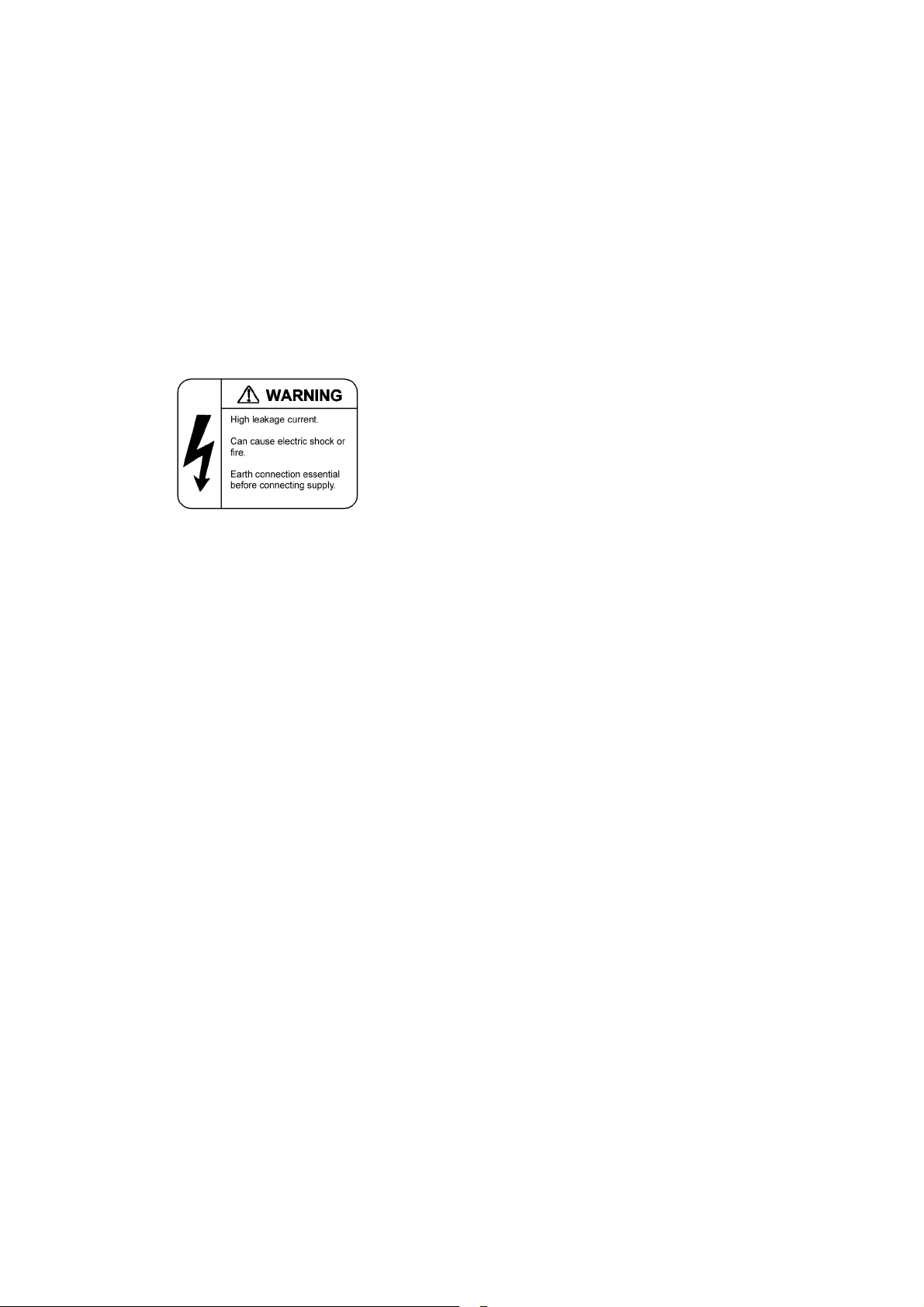
■ Grounding is required.
• When the device is connected to the power supply of 100VAC, leak current of up to 3.5mA flows for each
device. Be sure to use the grounded outlet. If the power supply is used without grounding, an electric shock
may be caused and failures may occur due to electric noise.
• When the device is connected to the power supply of 200VAC, leak current of up to 5mA flows for each
device. Choose a grounded outlet and make sure that the outlet is grounded to a ground plate in the
building. Request the maintenance personnel or specialized installation workers to check the grounding. If
the power supply is used without grounding, an electric shock may be caused and failures may occur due
to electric noise. The label below is attached to the device.
• When the device is connected to the DC power supply, be sure to connect the grounding terminal. If the
power supply is used without grounding, an electric shock may be caused and failures may occur due to
electric noise.
■ Installing/uninstalling of the DC power cable must be performed by the trained
engineer or maintenance personnel.
• Installing/uninstalling of the DC power cable must be performed by the trained engineer or maintenance
personnel. DC power cable is connected to the power supply via a terminal. Therefore, inadvertent
handling of the DC power cable may result in fire disasters or electric shock.
■ Before installing or removing a DC power cable, turn off the breaker on power supply
facilities.
• Before installing or removing a DC power cable, turn off the breaker on power supply facilities. Operation
with the breaker on may cause electric shock.
■ Attach insulation covers on the 0V and -48V terminals of a DC power cable.
• Attach insulation covers on the 0V and -48V terminals of a DC power cable (the side of which connects to
power supply facilities). Operation without insulation covers may cause electric shock.
■ When using the DC power supply, do not leave the terminal board uncovered.
• When using the DC power supply, be sure to attach the cover to the terminal board after connecting the
power cable. Operating it without the terminal board cover can cause an electric shock.
■ Do not touch the potential tap.
• The power supply is provided with the potential tap. This tap is used for inspection at shipment. Customer
should not use this tap. Do not insert a sharp material such as pin or clip into the potential tap. Fire disasters
or electric shock may be caused.
vii
Safety Guide [IP8800/S6700]
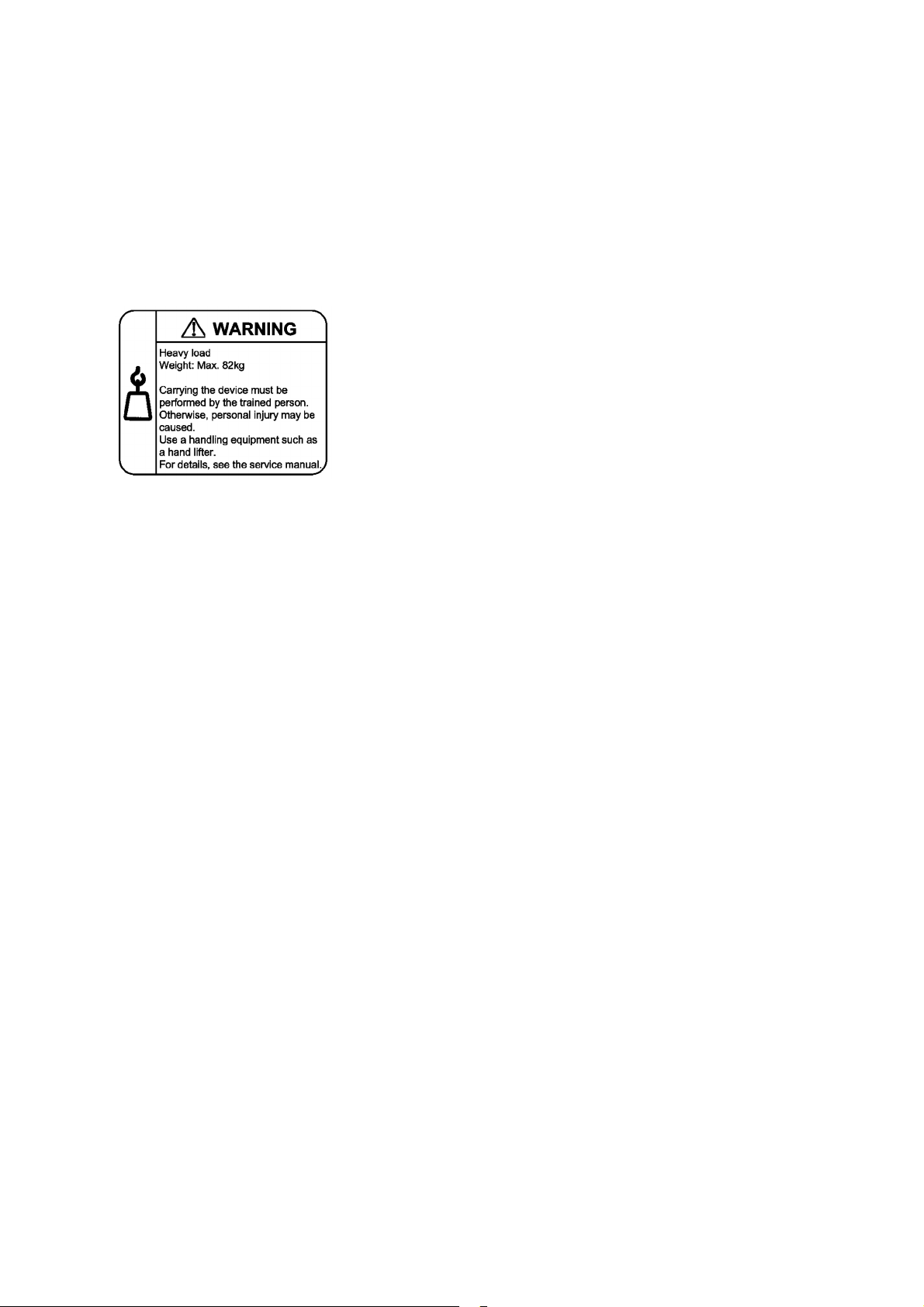
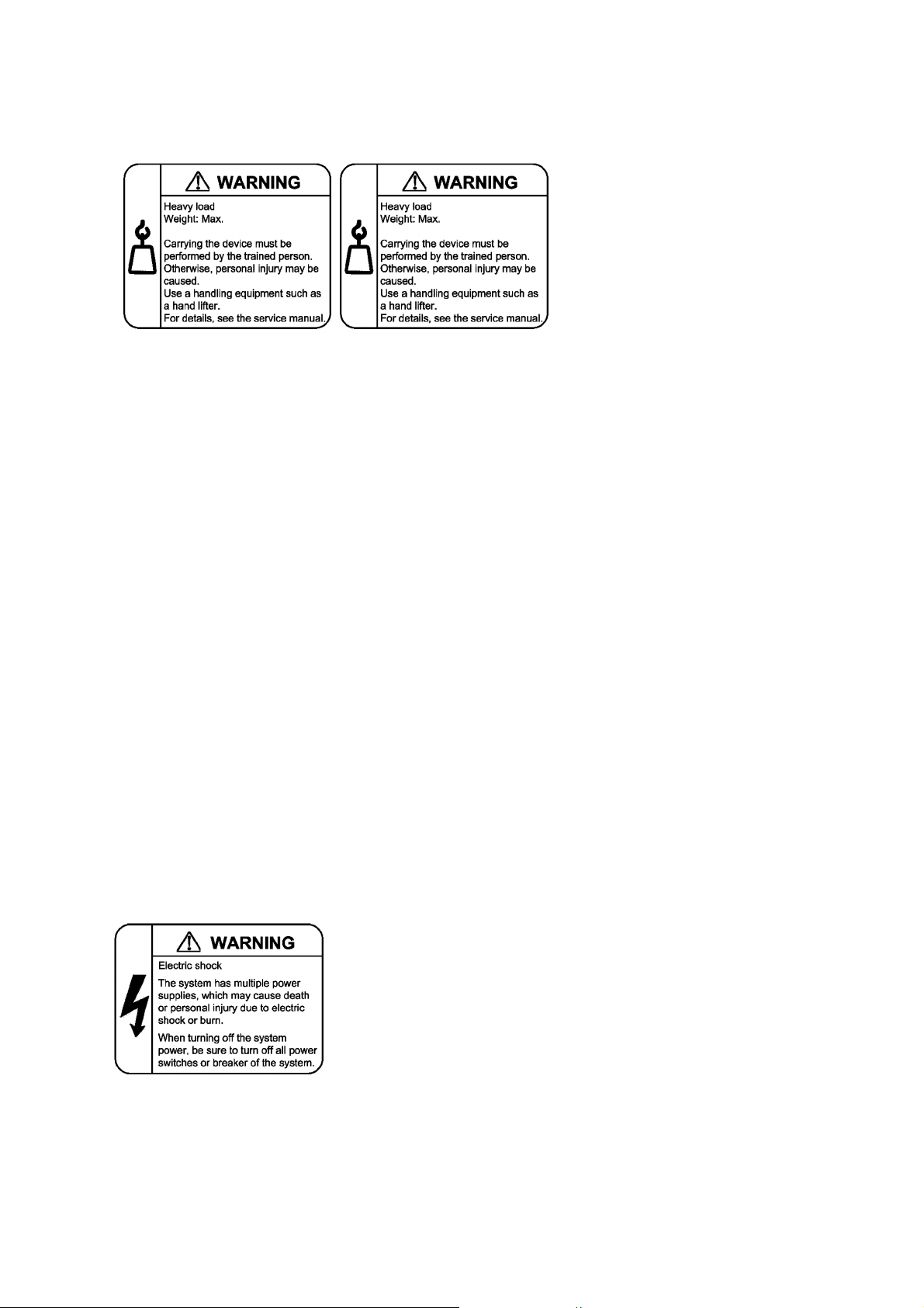
■ The device must be carried and installed by the trained personnel or specialized
carrier.
• The weight of the device is 82 kg/182 lb at the maximum. The device must be carried and installed by the
trained personnel or specialized carrier. Otherwise, a personal injury due to drop or fall may be caused.
For installation and carrying of the device, use a handling equipment such as a hand lifter. Otherwise, a
personal injury due to drop or fall may be caused. The label below is attached to the device.
■ Handle the power cable with caution.
• Do not put a heavy material on the power cable or do not pull, bend, or modify the power cable. The power
cable will be damaged and fire disasters or electric shock may be caused. A heavy material may be placed
as a result of covering the cable with a floor carpet.
• Use the attached power cable or the power cable complying with the specifications. If any other cable is
used, fire disasters or electric shock may be caused. Do not use the attached power cable for other
purposes. In such a case, fire disasters or electric shock may be caused.
• If the power cable is degraded (e.g., wire cores exposed or broken), ask the service personnel for
replacement. Otherwise it can cause a fire or electric shock.
• Check to see if dust is deposited on the power plug. Insert the plug securely to the end so that shakiness
will not occur. If dust is deposited or connection is incomplete, fire disasters or electric shock may be
caused.
■ Do not plug too many leads into a single outlet.
• Do not plug too many power plugs into a single outlet. Many loads on an electrical outlet may result in fire
disasters and the electric energy in use may be exceeded, the breaker may go off, and other components
may be affected.
viii
Safety Guide [IP8800/S6700]
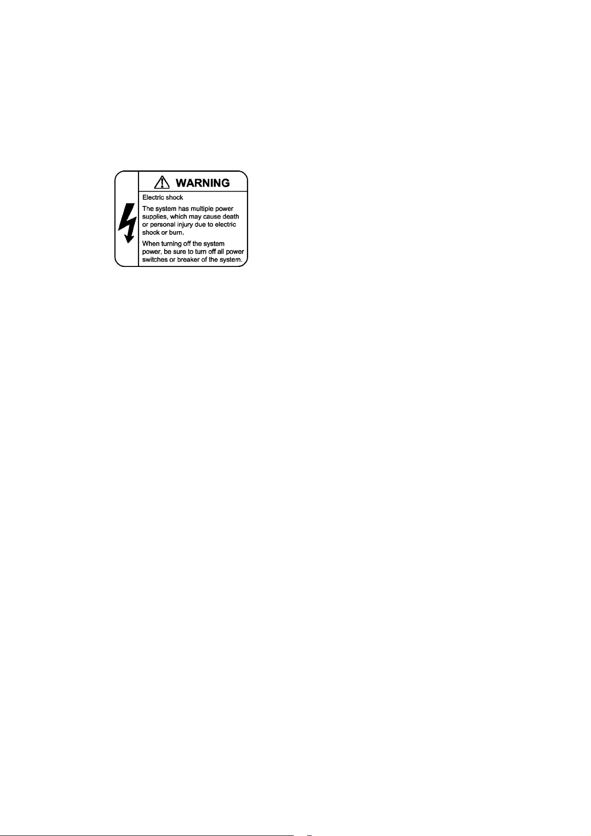
■ Before powering off, turn off all power switches or breakers on the device.
• Multiple input power supplies are provided to the device. Before powering off, turn off all power switches
(when AC power supply is mounted) or breakers (when DC power supply is mounted) on the device. The
label below is attached to the device.
■ Work to add or replace equipment must be performed by a trained engineer or
maintenance personnel.
• To add or replace optional components must be performed by a trained engineer or maintenance
personnel. To add or replace a power supply involves to plug and unplug power cables; a person other than
the preceding ones may fail to handle things, which can cause fire disaster, electric shock, and equipment
failure. Other optional components, if handled mistakenly, can also cause fire disaster, wounds, and
equipment failure.
■ Do not press the switch on the basic control unit with a fragile tip, pin, or clip that may
get stuck and cannot be removed.
• Do not press the switch on the front panel of the basic control unit with a fragile tip, pin, or clip that may get
stuck and cannot be removed. Fire disasters or electric shock may be caused.
■ Before addition or replacement of the power supply, unplug the power cable.
• Remove the power cable from the power supply when adding or replacing it. With the power cable
connected, the power supply equipment may remain energized from some circuits even the power switch
is turned off. Therefore, adding or replacing the power supply with the power cable connected may cause
a fire or electric shock.
■ Keep air dusters away from fire.
• If you use an air duster with combustible gas to clean the optical connector, keep away from fire. Otherwise,
fire disaster may occur.
ix

Safety Guide [IP8800/S6700]
CAUTION
■ Do not install the device in a humid or dusty environment.
• Do not install the device in a humid or dusty environment. Fire disasters or electric shock may be caused.
• Moving the device from a cold place to a warm place may form condensation on the surface or internal of
the device. If the device is operated immediately a fire or electric shock can be caused. Thus, in this case,
leave the device as it is for several hours before starting operation.
■ Do not stack the devices.
• Do not stack the devices. The device may be damaged. The device may be damaged or lose its balance
and fall or drop. As a result, personal injury may occur.
■ Do not recline on the device, or place a heavy loading on it.
• Do not ride on or cling to the device or do not put a heavy material on it. The device may be damaged. The
device may be damaged or lose its balance and fall or drop. As a result, personal injury may occur.
■ When installing the device on the rack, use the guide rail or shelf.
• The rack mounting bracket supplied with this device is used to fasten the device on the rack but not to
support the weight of the device. Be sure to use the guide rail or shelf. The guide rail or shelf must be the
one attached to the rack and capable of supporting the weight of the fully mounted switch.
■ Do not block the intake and/or exhaust port.
• Do not block the intake/exhaust port of the device. Blocking the intake/exhaust port keeps heat inside and
fire disasters may be caused. Keep a space of at least 70mm from the intake/exhaust port.
■ Do not bring hairs or any foreign matters close to the intake/exhaust port of the
device.
• The cooling fan unit is provided on the device. Do not put any material close to the intake/exhaust port. The
internal temperature rise may result in a failure. Do not put hair or any material close to the intake/exhaust
port. You may be caught and injured.
■ When moving an optional component, do not carry it by holding its handle.
• When moving a fan unit or power supply, do not hold its handle. The handle may come off and the device
may drop. As a result, a personal injury may occur. Or the fan unit or power supply may be deformed that
may cause a fire or electric shock.
■ Before carrying the device, remove the cables.
• When moving the device, power off the device, remove all the cables from the device, and then move the
device. Otherwise the device or cable may be deformed or damaged. As a result, fire disasters or electric
shock may be caused.
x
Safety Guide [IP8800/S6700]
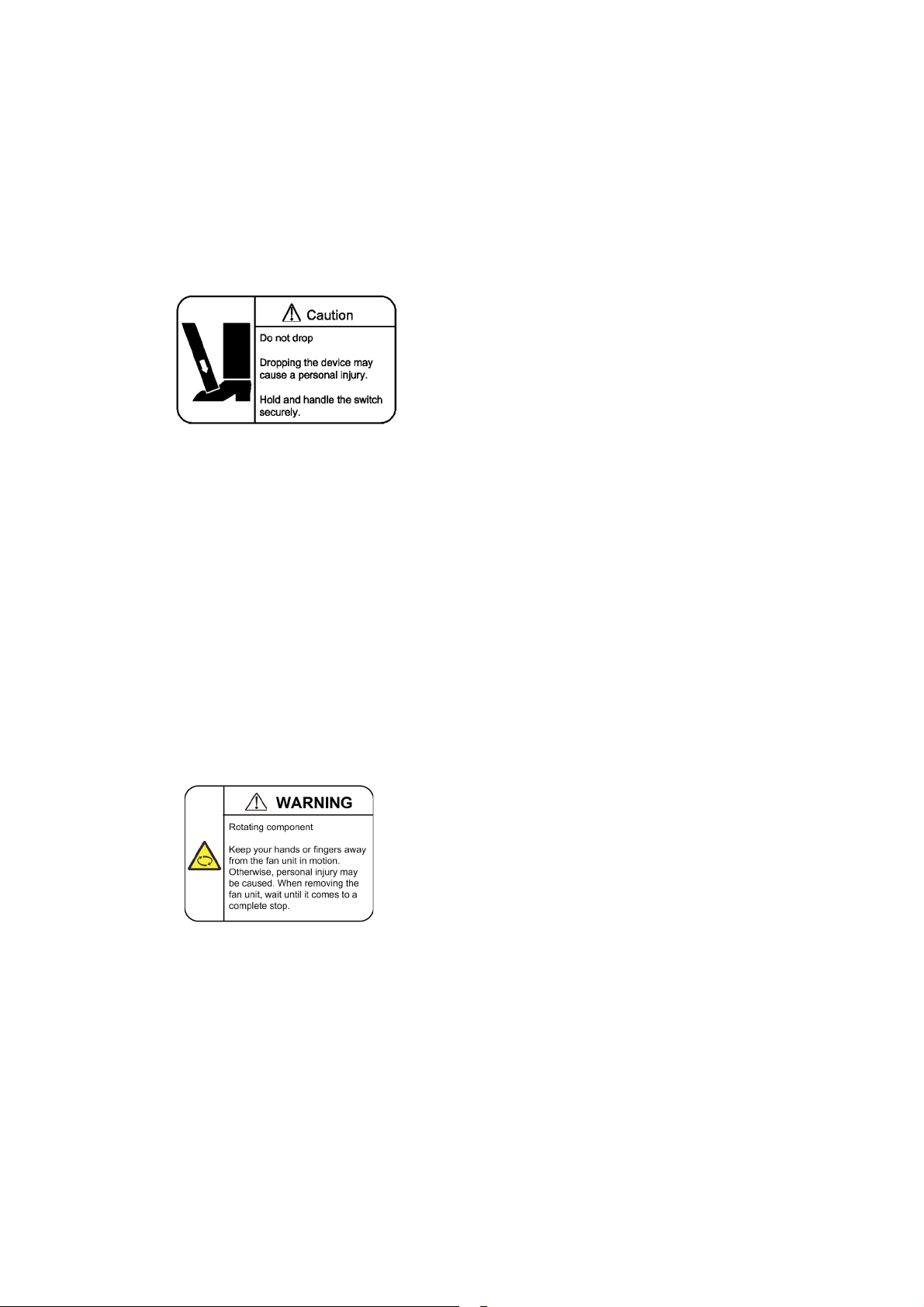
■ Do not drop an optional component.
• Handle the optional component carefully not to drop it. If dropped, personal injury may be caused.
• The weight and depth of the DC power supply are 5.6 kg/12.4 lb and 163 mm/6.4 in respectively. When
removing the DC power supply, hold it securely. If pulling it forward carelessly, it may drop and cause a
personal injury. The label below is attached to the DC power supply.
■ Do not touch the inside of the device.
• Do not put your hand inadvertently inside the device. Mechanical parts may cause a personal injury.
■ The basic control unit and network interface component may be hot. Be careful when
removing them.
• Parts mounted on the basic control unit and network interface component may be hot: Do not touch them
to prevent getting burned.
■ When removing the fan unit, do not put your hand close to the rotating fan.
• The fan may still be rotating immediately after the removal of the fan unit. While the fan is rotating, do not
put your hand or finger close to it. Personal injury may be caused. The label below is attached to the fan
unit.
■ Do not roughly handle the power cable.
• Do not put the power cable close to the heating apparatus. The cable sheath may be melted and fire
disasters or electric shock may be caused.
• When inserting the power cable into the outlet or removing from it, be sure to hold the cable plug. Pulling
up the cable with the cable grasped, the wire can be broken.
■ Do not touch the device directly if you have metal allergies.
• This device is coated with metals including zinc, nickel, and gold. If you have allergies to them, do not touch
the device directly to prevent getting dermatitis.
xi
Safety Guide [IP8800/S6700]
Caution. Hot! (all sides)
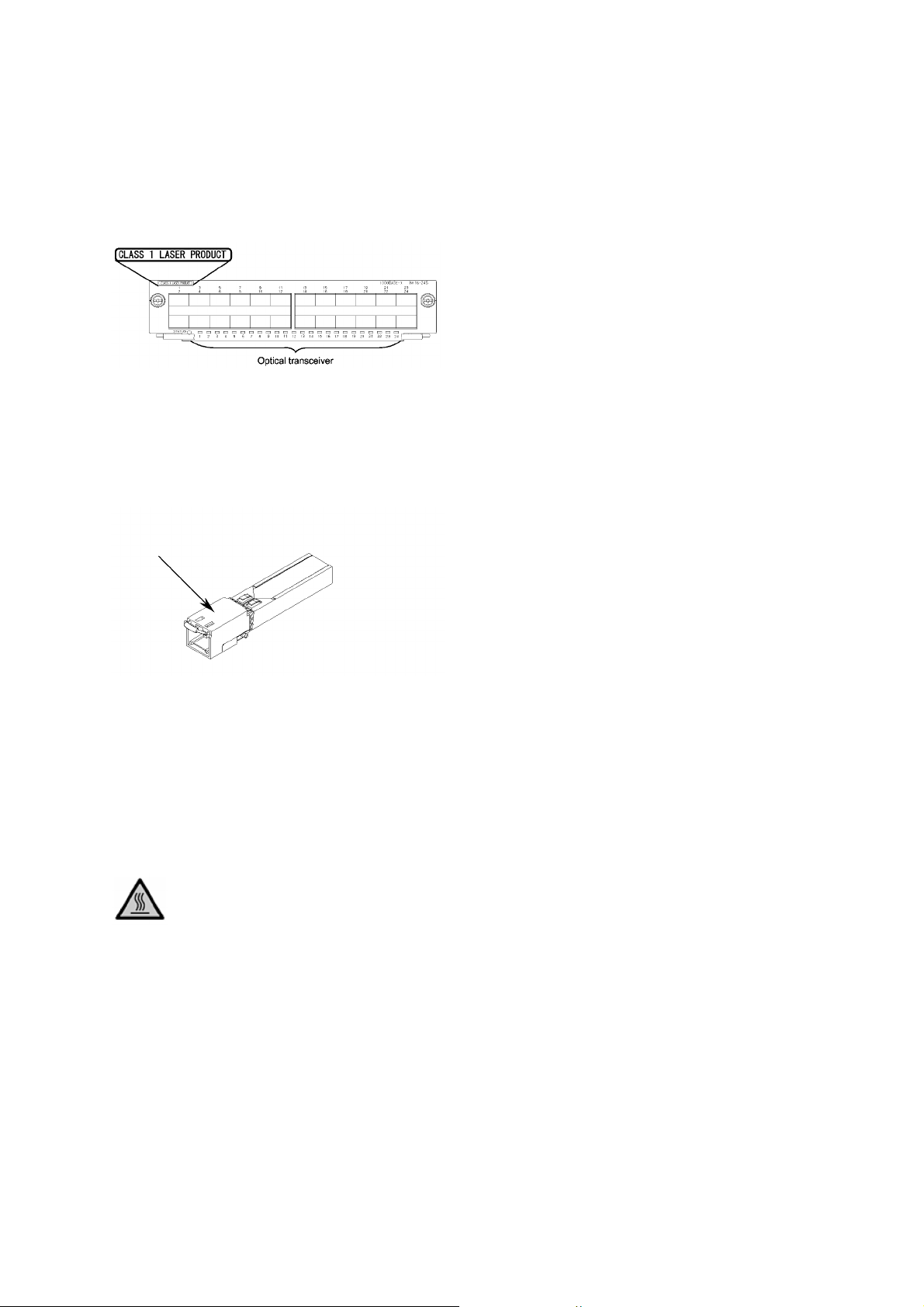
■ Be careful of laser beams.
• The network interface module as indicated below uses laser beams. Do not peep in the optical transceiver
directly.
■ Do not touch a working (including immediately after stopping) SFP-T.
• A working (establishing a link) SFT-P can have up to 65 °C/140 °F in temperature. Do not touch it when
working or immediately after stopping to prevent getting burned.
• To remove an SFP-T, follow the following procedures. Otherwise, you may get burned.
• To remove an SFP-T without turning off the device, execute the inactivate command, and remove the SFP-T
five minutes later.
• To remove an SFP-T from the device turned off, power off the switch of the device, and remove the SFP-T five
minutes later.
• An SFP-T has the following label attached.
■ Lithium battery
• This device mounts a lithium battery for the real-time clock. If the lithium battery is inadvertently handled,
a personal injury or fire may be caused as a result of heat generation, burst, or ignition. Do not remove the
lithium battery from the device or disassemble it, heat it to 100
water.
■ Cleaning
• Remove dust on and around the device on a regular basis. Device shutdown and fire disasters or electric
shock may be caused.
°C/212 °F or higher, burn it, or wet it with
xii

Safety Guide [IP8800/S6700]
CAUTION
■ Do not power off the device during software update (when the ppupdate command
is being executed).
• By the execution of the ppupdate command, the device automatically restarts. Do not power off the device
during restart (until the STATUS LED on the basic control unit changes from blinking in green into steady
light). The device may be damaged.
■ Handle a memory card with care.
• Do not forcedly push or flip a memory card to insert. Do not forcedly pull out a locked memory card to
remove. Otherwise, the connector of the memory card slot may be damaged.
• Remove the memory card to reposition the device. Moving the device may cause force against the memory
card, which can damage the connector of the memory card slot.
■ Do not remove the memory card or disconnect power while the ACC LED is lit.
• Lighting of the ACC LED on the basic control unit indicates that the memory card is being accessed. Do
not remove the memory card or disconnect power during access. The memory card may be damaged.
Some commands require a considerable time before completing access to the memory card after the entry
of the commands. Ensure that access is completed and then remove the memory card or disconnect
power.
■ Do not attach a label or the like to the transceivers.
• The transceiver has a label indicating its manufacturer and that it is our standard supply. However, this label
is attached to the part that does not obstruct heat radiation from the transceiver or the mechanism
preventing slip-off from the cage. If a label or the like is attached to such an obstructing part, the transceiver
or the network interface module may be damaged.
■ For the power supply equipment, considerations must be given not to cause voltage
drop due to rush current.
• When this device is powered on, a rush current flows. Considerations must be given not to cause voltage
drop due to such a rush current. The voltage drop affects not only this device but other devices connected
to the same power supply equipment.
■ When installing/uninstalling the power cable, turn off the power switch.
• To install or uninstall the power cable, turn off the switch on the power supply to be installed or uninstalled.
■ When replacing the fan unit while the device powered on, complete the task within
the specified duration of time.
• When replacing the fan unit while the device powered on, complete the entire task from removal to
installation within one minute. If it takes more than one minute, other modules may be affected by
temperature rise in the device.
xiii
Safety Guide [IP8800/S6700]
■ For carrying or packaging the device and optional component, use an antistatic wrist
strap.
• Use an antistatic wrist strap. If you handle the device without the antistatic wrist strap, the device can be
damaged by the static electricity.
■ After removing an optional component, be sure to attach a blank panel.
• After removing an optional component, be sure to attach a blank panel. Using the device without the blank
panel attached, the air flow in the device cannot be maintained. In such a case, the temperature rise inside
the device may cause a failure.
■ Attach an option component with care.
• Follow the following procedures to attach an option component. Otherwise, a problem may occur on the
device.
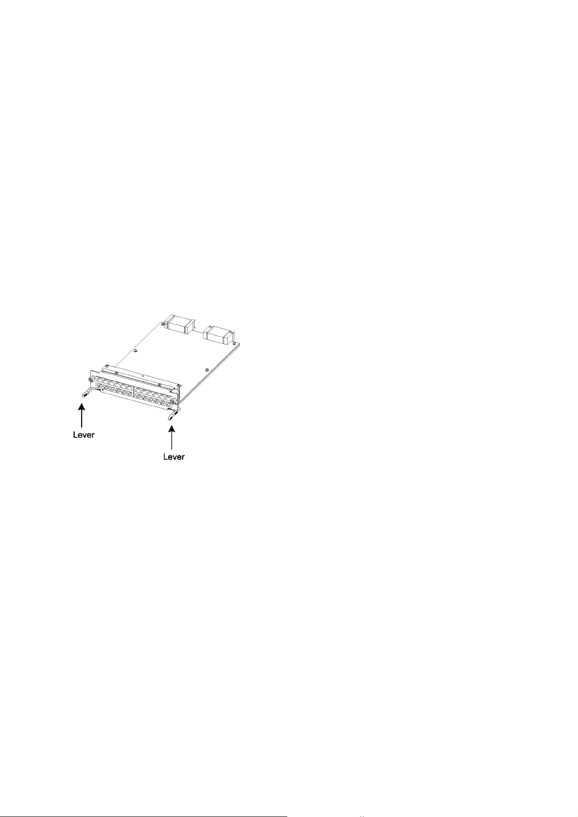
1. Open the levers as the figure below.
2. With the levers in hands, push the component slowly into the device, to the point where the levers touch the device.
3. Use the levers to insert the component all the way. Move the levers slowly (taking more than one second) but not forcedly.
■ Before removing an optional component, loosen the screws completely.
• Use levers to remove the basic control unit, basic switching unit or network interface module. If screws are
not completely loosened, the optional component may be damaged when the levers are pressed down.
■ When carrying or packing an optional component, take care for handling.
• Take care not to handle the connector when carrying or packing optional components such as the basic
control unit, basic switching unit, network interface module, memory card, transceiver, and power supply.
They must be stored in antistatic bags when they are not in use.
■ Do not install the device in any place possibly reaching a high temperature.
• Be careful that the parts may be damaged if left in a place exposed to direct sunlight or close to a heating
apparatus.
xiv

Safety Guide [IP8800/S6700]
■ Do not bring a TV or radio close to the device.
• Leaving a TV or radio close to the device can adversely influence to each other. If a TV or radio interferes
the device, remedy as follows:
1. Keep the device from the television or radio set as far away as possible.
2. Change the direction of the antenna for the television or radio set.
3. Use different outlets.
■ Keep the device away from a place with hydrogen sulfide or much salt.
• Places with hydrogen sulfide including hot spring resorts, and places with much salt including coasts may
shorten lifetime of the device.
■ Use air dusters with care.
• Choose an air duster designated to clean optical connectors. Other air dusters may get the end face of the
ferrule dirty.
• Avoid the nozzle or container of an air duster from touching the end face of the ferrule. Otherwise, the
ferrule may be damaged.
■ Handle the optical connector with care.
• Use the designated optical connector cleaner. Other optical connector cleaners may get the end face of
the ferrule dirty.
• Make sure of no problems on the head part of an optical connector cleaner, including attached fabric,
grime, and other foreign substances. Otherwise, the end face of the ferrule may be damaged.
• Do not push the optical connector forcedly to clean. Otherwise, the end face of the ferrule may be
damaged.
• Rotate an optical connector cleaner (stick type) only in a clockwise direction. An optical connector cleaner
rotating clockwise as well as counterclockwise may damage the end face of the ferrule.
■ Maintenance and cleaning
• Wipe off the dirt on the device's outer surface with a dry, clean cloth or a well-wrung wet cloth containing
water or neutral cleanser. Do not apply volatile organic solvents or chemicals including benzine and thinner
pre-moistened cloths or insect killers, since they can deform, discolor or damage the device.
■ Long-term downtime
• For a long downtime, such as due to a long vacation or travel, be sure to unplug the power cable from the
wall outlet for safety. For a configuration using DC power supply, turn off the breaker on the power facility.
■ Discarding this device
• Discard the device according to the ordinance or rule of the local government or call the local waste
material handling facility.
xv

Safety Guide [IP8800/S6600]
■ Safety guide for the IP8800/S6600 series
• This document provides safety-related notices for use of the IP8800/S6600 series. To utilize the functions of
this device, read this document completely and carefully before using the device.
• Keep this document at hand after you read it, so that you can always refer it later.
• For any operation, follow the directions and procedures given by this document.
• Observe the cautions labeled on the device or those presented by this document. If you fail to do so, you will
cause damage to yourself or the device.
■ Symbols
• We have various symbols displayed on the IP8800/S6600 series and in the manuals to guide you in using the
IP8800/S6600 series correctly and safely without injuring yourself and others, or damaging equipment assets.
Below are the symbols and their meanings. Fully understand the description and then proceed with reading
the main part of the manual.
If you ignore instructions preceded by this symbol, you could cause personal injury or
WARNING
death to yourself and others.
If you ignore instructions preceded by this symbol, you could cause personal injury to
CAUTION
CAUTION
NOTE
yourself and others, or serious damage to the device or surroundings.
If you ignore instructions preceded by this symbol, you could cause physical damage
to the device or surroundings.
A note is informational in nature. Unlike warning and caution notices, notes (for
prevention of malfunction, prevention of product minor damages) are not related to the
physical injury or damage to the device.
■ Operations and actions
• Do not attempt to perform any operations not specifically described in this document.
In case of a problem on the device, contact the maintenance personnel after performing the following.
• For the device with AC power supply mounted, power off the device and unplug the power cable from the outlet.
• For the device with DC power supply mounted, power off the device and turn off the breaker in the power supply
equipment.
■ Be careful in operation
• The instructions displayed on the device or in this manual are the results of our thorough consideration.
However, an unexpected situation may occur. For operations, not only follow the instructions but also always
be careful yourself.
xvii

Safety Guide [IP8800/S6600]
WARNING
■ In case a failure should occur, power off the device immediately.
• In case fume or unusual odor should occur, or foreign matters should come into the device, power off the device
as follows. If the device is used in a faulty state, fire disasters or electric shock may be caused.
• For the device with AC power supply mounted, power off the device and unplug the power cable from the outlet.
• For the device with DC power supply mounted, power off the device and turn off the breaker in the power supply
equipment because the power cable is connected via a terminal.
■ Do not place the device in an unstable location.
• If the device is being placed on a table, be sure to install it horizontally on a workbench or the like that can
sufficiently bear the weight of the device. If the device is placed on an unstable location such on a shaky table
or slope, the device may fall and drop and consequently personal injury may occur.
■ Do not remove the device cover.
• Do not remove the device cover. Electric shock may be caused.
■ Do not put foreign matters in the device.
• Do not insert or drop metals or combustibles into the device through the intake/exhaust port. Fire disasters or
electric shock may be caused.
■ Modification is not permissible.
• Device modification is not permissible. Fire disasters or electric shock may be caused.
■ Do not give a shock.
• In case the device is dropped or parts are damaged, power off the device, pull the cable out of the outlet, and
call the maintenance engineer. Otherwise it can cause a fire or electric shock.
■ Do not put any material on the device.
• Do not put a metal such as pin or clip or a container with water in it such as vase or flower pot on the device.
Fire disasters or electric shock may be caused.
■ Do not use power not specified.
• Do not use a supply voltage not specified. Fire disasters or electric shock may be caused.
■ The current capacity supplied to the power distribution panel must be larger than the
operating current of the breaker.
• The current capacity supplied to the power distribution panel must be larger than the operating current of the
breaker. Otherwise, the breaker may not work in the event of a failure and cause fire disasters.
xviii

Safety Guide [IP8800/S6600]
■ Grounding is required.
• Leak current of up to 3.5mA flows for each device. If connecting the device with AC power, be sure to use the
grounded outlet. If the power supply is used without grounding, an electric shock may be caused and failures
may occur due to electric noise.
• When the device is connected to the DC power supply, be sure to connect the grounding terminal. If the power
supply is used without grounding, an electric shock may be caused and failures may occur due to electric
noise.
■ Installing/uninstalling of the DC power cable must be performed by the trained
engineer or maintenance personnel.
• Installing/uninstalling of the DC power cable must be performed by the trained engineer or maintenance
personnel. DC power cable is connected to the power supply via a terminal. Therefore, inadvertent handling
of the DC power cable may result in fire disasters or electric shock.
■ Before installing or removing a DC power cable, turn off the breaker on power supply
facilities.
• Before installing or removing a DC power cable, turn off the breaker on power supply facilities. Operation with
the breaker on may cause electric shock.
■ Attach insulation covers on the 0V and -48V terminals of a DC power cable.
• Attach insulation covers on the 0V and -48V terminals of a DC power cable (the side of which connects to
power supply facilities). Operation without insulation covers may cause electric shock.
■ When using the DC power supply, do not leave the terminal board uncovered.
• When using the DC power supply, be sure to attach the cover to the terminal board after connecting the power
cable. Operating it without the terminal board cover can cause an electric shock.
■ Do not touch the potential tap.
• The power supply is provided with the potential tap. This tap is used for inspection at shipment. Customer
should not use this tap. Do not insert a sharp material such as pin or clip into the potential tap. Fire disasters
or electric shock may be caused.
■ The device must be carried and installed by at least three people.
• The table below shows mass of the devices. The device must be carried and installed by at least three people.
Otherwise, a personal injury due to drop or fall may be caused.
Number of people to carry the device
Model Mass Number of people
IP8800/S6604 45 kg/100 lb 3 or more
IP8800/S6608 64 kg/142 lb
xix
Safety Guide [IP8800/S6600]
45kg 64kg
IP8800/S6604 IP8800/S6608
The label below is attached to the device.
■ Handle the power cable with caution.
• Do not put a heavy material on the power cable or do not pull, bend, or modify the power cable. The power
cable will be damaged and fire disasters or electric shock may be caused. A heavy material may be placed as
a result of covering the cable with a floor carpet.
• Use the attached power cable or the power cable complying with the specifications. If any other cable is used,
fire disasters or electric shock may be caused. Do not use the attached power cable for other purposes. In such
a case, fire disasters or electric shock may be caused.
• If the power cable is degraded (e.g., wire cores exposed or broken), ask the service personnel for replacement.
Otherwise it can cause a fire or electric shock.
• Check to see if dust is deposited on the power plug. Insert the plug securely to the end so that shakiness will
not occur. If dust is deposited or connection is incomplete, fire disasters or electric shock may be caused.
■ Do not plug too many leads into a single outlet.
• Do not plug too many power plugs into a single outlet. Many loads on an electrical outlet may result in fire
disasters and the electric energy in use may be exceeded, the breaker may go off, and other components may
be affected.
■ Before powering off, turn off all power switches or breakers on the device.
• Multiple input power supplies are provided to the device. Before powering off, turn off all power switches (when
AC power supply is mounted) or breakers (when DC power supply is mounted) on the device. The label below
is attached to the device.
xx

Safety Guide [IP8800/S6600]
■ Work to add or replace equipment must be performed by a trained engineer or
maintenance personnel.
• To add or replace optional components must be performed by a trained engineer or maintenance personnel.
To add or replace a power supply involves to plug and unplug power cables; a person other than the preceding
ones may fail to handle things, which can cause fire disaster, electric shock, and equipment failure. Other
optional components, if handled mistakenly, can also cause fire disaster, wounds, and equipment failure.
■ Do not press the switch on the basic control unit with a fragile tip, pin, or clip that may
get stuck and cannot be removed.
• Do not press the switch on the front panel of the basic control unit with a fragile tip, pin, or clip that may get
stuck and cannot be removed. Fire disasters or electric shock may be caused.
■ Before addition or replacement of the power supply, unplug the power cable.
• Remove the power cable from the power supply when adding or replacing it. With the power cable connected,
the power supply equipment may remain energized from some circuits even the power switch is turned off.
Therefore, adding or replacing the power supply with the power cable connected may cause a fire or electric
shock.
■ Keep air dusters away from fire.
• If you use an air duster with combustible gas to clean the optical connector, keep away from fire. Otherwise,
fire disaster may occur.
xxi

Safety Guide [IP8800/S6600]
CAUTION
■ Do not install the device in a humid or dusty environment.
• Do not install the device in a humid or dusty environment. Fire disasters or electric shock may be caused.
• Moving the device from a cold place to a warm place may form condensation on the surface or internal of the
device. If the device is operated immediately a fire or electric shock can be caused. Thus, in this case, leave
the device as it is for several hours before starting operation.
■ Do not stack the devices.
• Do not stack the devices. The device may be damaged. The device may be damaged or lose its balance and
fall or drop. As a result, personal injury may occur.
■ Do not recline on the device, or place a heavy loading on it.
• Do not ride on or cling to the device or do not put a heavy material on it. The device may be damaged. The
device may be damaged or lose its balance and fall or drop. As a result, personal injury may occur.
■ When installing the device on the rack, use brackets to support the weight of the
device.
• The rack-attaching brackets supplied with this device are used to fasten the device on the rack but not to
support the weight of the device. Use either of the following.
Model Items
IP8800/S6604
IP8800/S6608
The guide rail or shelf, if you use, must be the one attached to the rack and capable of supporting the weight
of the fully mounted device.
guide rail, shelf, support brackets
guide rail, shelf
■ Use support brackets only for IP8800/S6604.
• The support brackets support only IP8800/S6604. Do not use for others. Otherwise, the equipment may fall or
drop and damage you.
■ Use support brackets with care.
• When you mount the device on a rack with support brackets, support the device flatly from both front and rear
sides while mounting the device and fastening screws. A tilted device may fall or drop and damage you and
other equipment mounted on the same rack.
• To mount the device on a rack with support brackets means weight of the device is supported only by
rack-attaching brackets and the support brackets. Make sure to fasten screws of the rack-attaching brackets
and the support brackets tightly.
xxii

Safety Guide [IP8800/S6600]
■ Do not block the intake and/or exhaust port.
• Do not block the intake/exhaust port of the device. Blocking the intake/exhaust port keeps heat inside and fire
disasters may be caused. Keep a space of at least 70mm from the intake/exhaust port.
■ Do not bring hairs or any foreign matters close to the intake/exhaust port of the
device.
• The cooling fan unit is provided on the device. Do not put any material close to the intake/exhaust port. The
internal temperature rise may result in a failure. Do not put hair or any material close to the intake/exhaust port.
You may be caught and injured.
■ When moving an optional component, do not carry it by holding its handle.
• When moving a fan unit or power supply, do not hold its handle. The handle may come off and the device may
drop. As a result, a personal injury may occur. Or the fan unit or power supply may be deformed that may cause
a fire or electric shock.
■ Before carrying the device, remove the cables.
• When moving the device, power off the device, remove all the cables from the device, and then move the
device. Otherwise the device or cable may be deformed or damaged. As a result, fire disasters or electric shock
may be caused.
■ Do not drop an optional component.
• Handle the optional component carefully not to drop it. If dropped, personal injury may be caused.
• The weight and depth of the DC power supply are 5.6kg and 163mm respectively. When removing the DC
power supply, hold it securely. If pulling it forward carelessly, it may drop and cause a personal injury. The label
below is attached to the DC power supply.
■ Do not touch the inside of the device.
• Do not put your hand inadvertently inside the device. Mechanical parts may cause a personal injury.
■ The basic switching unit and network interface component may be hot. Be careful
when removing them.
• Parts mounted on the basic switching unit and network interface component may be hot: Do not touch them to
prevent getting burned.
xxiii

Safety Guide [IP8800/S6600]
■ When removing the fan unit, do not put your hand close to the rotating fan.
• The fan may still be rotating immediately after the removal of the fan unit. While the fan is rotating, do not put
your hand or finger close to it. Personal injury may be caused. The label below is attached to the fan unit.
■ Do not roughly handle the power cable.
• Do not put the power cable close to the heating apparatus. The cable sheath may be melted and fire disasters
or electric shock may be caused.
• When inserting the power cable into the outlet or removing from it, be sure to hold the cable plug. Pulling up
the cable with the cable grasped, the wire can be broken.
■ Do not touch the device directly if you have metal allergies.
• This device is coated with metals including zinc, nickel, and gold. If you have allergies to them, do not touch
the device directly to prevent getting dermatitis.
■ Be careful of laser beams.
• The network interface module as indicated below uses laser beams. Do not peep in the optical transceiver
directly.
xxiv

Safety Guide [IP8800/S6600]
Caution. Hot! (all sides)
■ Do not touch a working (including immediately after stopping) SFP-T.
• A working (establishing a link) SFT-P can have up to 65 °C/140 °F in temperature. Do not touch it when working
or immediately after stopping to prevent getting burned.
• To remove an SFP-T, follow the following procedures. Otherwise, you may get burned.
• To remove an SFP-T without turning off the device, execute the inactivate command, and remove the SFP-T
five minutes later.
• To remove an SFP-T from the device turned off, power off the switch of the device, and remove the SFP-T five
minutes later.
• An SFP-T has the following label attached.
■ Lithium battery
• This device mounts a lithium battery for the real-time clock. If the lithium battery is inadvertently handled, a
personal injury or fire may be caused as a result of heat generation, burst, or ignition. Do not remove the lithium
battery from the device or disassemble it, heat it to 100
°C/212 °F or higher, burn it, or wet it with water.
■ Cleaning
• Remove dust on and around the device on a regular basis. Device shutdown and fire disasters or electric shock
may be caused.
xxv

Safety Guide [IP8800/S6600]
CAUTION
■ Do not power off the device during software update (when the ppupdate command
is being executed).
• By the execution of the ppupdate command, the device automatically restarts. Do not power off the device
during restart (until the STATUS LED on the control swithcing unit changes from blinking in green into steady
light). The device may be damaged.
■ Handle a memory card with care.
• Do not forcedly push or flip a memory card to insert. Do not forcedly pull out a locked memory card to remove.
Otherwise, the connector of the memory card slot may be damaged.
• Remove a memory card to reposition the device. Moving the device may cause force against the memory card,
which can damage the connector of the memory card slot.
■ Do not remove the memory card or disconnect power while the ACC LED is lit.
• Lighting of the ACC LED on the basic switching unit indicates that the memory card is being accessed. Do not
remove the memory card or disconnect power during access. The memory card may be damaged. Some
commands require a considerable time before completing access to the memory card after the entry of the
commands. Ensure that access is completed and then remove the memory card or disconnect power.
■ Do not attach a label or the like to the transceivers.
• The transceiver has a label indicating its manufacturer and that it is our standard supply. However, this label is
attached to the part that does not obstruct heat radiation from the transceiver or the mechanism preventing
slip-off from the cage. If a label or the like is attached to such an obstructing part, the transceiver or the network
interface module may be damaged.
■ For the power supply equipment, considerations must be given not to cause voltage
drop due to rush current.
• When this device is powered on, a rush current flows. Considerations must be given not to cause voltage drop
due to such a rush current. The voltage drop affects not only this device but other devices connected to the
same power supply equipment.
■ When installing/uninstalling the power cable, turn off the power switch.
• To install or uninstall the power cable, turn off the switch on the power supply to be installed or uninstalled.
■ When replacing the fan unit while the device powered on, complete the task within
the specified duration of time.
• When replacing the fan unit while the device powered on, complete the entire task from removal to installation
within one minute. If it takes more than one minute, other modules may be affected by temperature rise in the
device.
xxvi

Safety Guide [IP8800/S6600]
■ For carrying or packaging the device and optional component, use an antistatic wrist
strap.
• Use an antistatic wrist strap. If you handle the device without the antistatic wrist strap, the device can be
damaged by the static electricity.
■ After removing an optional component, be sure to attach a blank panel.
• After removing an optional component, be sure to attach a blank panel. Using the device without the blank
panel attached, the air flow in the device cannot be maintained. In such a case, the temperature rise inside the
device may cause a failure.
■ Attach an option component with care.
• Follow the following procedures to attach an option component. Otherwise, a problem may occur on the device.
1. Open the levers as the figure below.
2. With the levers in hands, push the component slowly into the device, to the point where the levers touch the device.
3. Use the levers to insert the component all the way. Move the levers slowly (taking more than one second) but not forcedly.
■ Before removing an optional component, loosen the screws completely.
• Use levers to remove the basic switching unit or network interface module. If screws are not completely
loosened, the optional component may be damaged when the levers are pressed down.
■ When carrying or packing an optional component, take care for handling.
• Take care not to handle the connector when carrying or packing optional components such as the basic
switching unit, network interface module, memory card, transceiver, and power supply. They must be stored in
antistatic bags when they are not in use.
■ Do not install the device in any place possibly reaching a high temperature.
• Be careful that the parts may be damaged if left in a place exposed to direct sunlight or close to a heating
apparatus.
xxvii

Safety Guide [IP8800/S6600]
■ Do not bring a TV or radio close to the device.
• Leaving a TV or radio close to the device can adversely influence to each other. If a TV or radio interferes the
device, remedy as follows:
1. Keep the device from the television or radio set as far away as possible.
2. Change the direction of the antenna for the television or radio set.
3. Use different outlets.
■ Keep the device away from a place with hydrogen sulfide or much salt.
• Places with hydrogen sulfide including hot spring resorts, and places with much salt including coasts may
shorten lifetime of the device.
■ Use air dusters with care.
• Choose an air duster designated to clean optical connectors. Other air dusters may get the end face of the
ferrule dirty.
• Avoid the nozzle or container of an air duster from touching the end face of the ferrule. Otherwise, the ferrule
may be damaged.
■ Handle the optical connector with care.
• Use the designated optical connector cleaner. Other optical connector cleaners may get the end face of the
ferrule dirty.
• Make sure of no problems on the head part of an optical connector cleaner, including attached fabric, grime,
and other foreign substances. Otherwise, the end face of the ferrule may be damaged.
• Do not push the optical connector forcedly to clean. Otherwise, the end face of the ferrule may be damaged.
• Rotate an optical connector cleaner (stick type) only in a clockwise direction. An optical connector cleaner
rotating clockwise as well as counterclockwise may damage the end face of the ferrule.
■ Maintenance and cleaning
• Wipe off the dirt on the device's outer surface with a dry, clean cloth or a well-wrung wet cloth containing water
or neutral cleanser. Do not apply volatile organic solvents or chemicals including benzine and thinner
pre-moistened cloths or insect killers, since they can deform, discolor or damage the device.
■ Long-term downtime
• For a long downtime, such as due to a long vacation or travel, be sure to unplug the power cable from the wall
outlet for safety. For a configuration using DC power supply, turn off the breaker on the power facility.
■ Discarding this device
• Discard the device according to the ordinance or rule of the local government or call the local waste material
handling facility.
xxviii

Safety Guide [IP8800/S6300]
■ Safety guide for the IP8800/S6300 series
• This document provides safety-related notices for use of the IP8800/S6300 series. Read this document
completely and carefully before using the device.
• Keep this document at hand after you read it, so that you can always refer it later.
• For any operation, follow the directions and procedures given by this document.
• Observe the cautions labeled on the device or those presented by this document. If you fail to do so, you will
cause damage to yourself or the device.
■ Symbols
• We have various symbols displayed on the IP8800/S6300 series and in the manuals to guide you in using the
IP8800/S6300 series correctly and safely without injuring yourself and others, or damaging equipment assets.
Below are the symbols and their meanings. Fully understand the description and then proceed with reading
the main part of the manual.
If you ignore instructions preceded by this symbol, you could cause personal injury or
WARNING
death to yourself and others.
If you ignore instructions preceded by this symbol, you could cause personal injury to
CAUTION
CAUTION
NOTE
yourself and others, or serious damage to the device or surroundings.
If you ignore instructions preceded by this symbol, you could cause physical damage
to the device or surroundings.
A note is informational in nature. Unlike warning and caution notices, notes (for
prevention of malfunction, prevention of product minor damages) are not related to the
physical injury or damage to the device.
■ Operations and actions
• Do not attempt to perform any operations not specifically described in this document.
In case of a problem on the device, contact the maintenance personnel after performing the following.
• For the device with AC power supply mounted, power off the device and unplug the power cable from the outlet.
• For the device with DC power supply mounted, power off the device and turn off the breaker in the power supply
equipment.
■ Be careful in operation
The instructions displayed on the device or in this manual are the results of our thorough consideration.
• However, an unexpected situation may occur. For operations, not only follow the instructions but also always
be careful yourself.
xxix

Safety Guide [IP8800/S6300]
WARNING
■ In case a failure should occur, power off the device immediately.
• In case fume or unusual odor should occur, or foreign matters should come into the device, power off the device
as follows. If the device is used in a faulty state, fire disasters or electric shock may be caused.
• For the device with AC power supply mounted, power off the device and unplug the power cable from the outlet.
• For the device with DC power supply mounted, power off the device and turn off the breaker in the power supply
equipment because the power cable is connected via a terminal.
■ Do not place the device in an unstable location.
• If the device is being placed on a table, be sure to install it horizontally on a workbench or the like that can
sufficiently bear the weight of the device. If the device is placed on an unstable location such on a shaky table
or slope, the device may fall and drop and consequently personal injury may occur.
■ Do not remove the device cover.
• Do not remove the device cover. Electric shock may be caused.
■ Do not put foreign matters in the device.
• Do not insert or drop metals or combustibles into the device through the intake/exhaust port. Fire disasters or
electric shock may be caused.
■ Modification is not permissible.
• Device modification is not permissible. Fire disasters or electric shock may be caused.
■ Do not give a shock.
• In case the device is dropped or parts are damaged, power off the device, pull the cable out of the outlet, and
call the maintenance engineer. Otherwise it can cause a fire or electric shock.
■ Do not put any material on the device.
• Do not put a metal such as pin or clip or a container with water in it such as vase or flower pot on the device.
Fire disasters or electric shock may be caused.
■ Do not use power not specified.
• Do not use a supply voltage not specified. Fire disasters or electric shock may be caused.
■ The current capacity supplied to the power distribution panel must be larger than the
operating current of the breaker.
• The current capacity supplied to the power distribution panel must be larger than the operating current of the
breaker. Otherwise, the breaker may not work in the event of a failure and cause fire disasters.
xxx

Safety Guide [IP8800/S6300]
■ Grounding is required.
• Leak current of up to 3.5mA flows for each device. For connecting to the AC power supply, be sure to use the
grounded outlet. If the power supply is used without grounding, an electric shock may be caused and failures
may occur due to electric noise.
• For connecting the DC power supply, be sure to connect the grounding terminal. If the power supply is used
without grounding, an electric shock may be caused and failures may occur due to electric noise.
■ Installing/uninstalling of the DC power cable must be performed by the trained
engineer or maintenance personnel.
• Installing/uninstalling of the DC power cable must be performed by the trained engineer or maintenance
personnel. DC power cable is connected to the power supply via a terminal. Therefore, inadvertent handling
of the DC power cable may result in fire disasters or electric shock.
■ Before installing or removing a DC power cable, turn off the breaker on power supply
facilities.
• Before installing or removing a DC power cable, turn off the breaker on power supply facilities. Operation with
the breaker on may cause electric shock.
■ Attach insulation covers on the 0V and -48V terminals of a DC power cable.
• Attach insulation covers on the 0V and -48V terminals of a DC power cable (the side of which connects to
power supply facilities). Operation without insulation covers may cause electric shock.
■ When using the DC power supply, do not leave the terminal board uncovered.
• When using the DC power supply, be sure to attach the cover to the terminal board after connecting the power
cable. Operating it without the terminal board cover can cause an electric shock.
■ Do not touch the potential tap.
• The power supply is provided with the potential tap. However, this tap is used for inspection at shipment.
Customer should not use this tap. Do not insert a sharp material such as pin or clip into the potential tap. Fire
disasters or electric shock may be caused.
xxxi
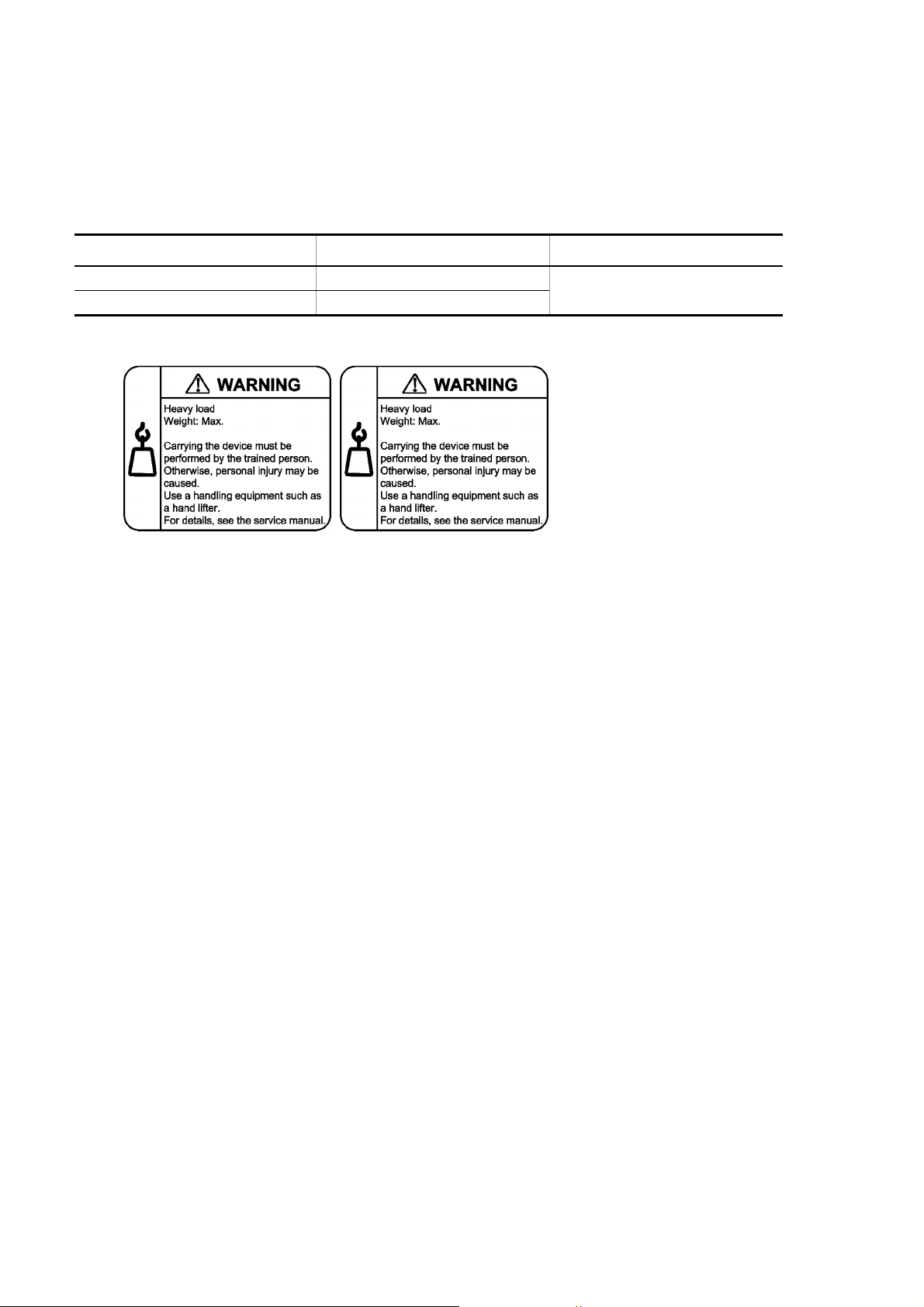
Safety Guide [IP8800/S6300]
45kg 64kg
IP8800/S6304 IP8800/S6308
■ The device must be carried and installed by at least three people.
• The table below shows mass of the devices. The device must be carried and installed by at least three people.
Otherwise, a personal injury due to drop or fall may be caused.
Number of people to carry the device
Model Mass Number of people
IP8800/S6304 45kg/100 lb 3 or more
IP8800/S6308 64kg/142 lb
The label below is attached to the device.
■ Handle the power cable with caution.
• Do not put a heavy material on the power cable or do not pull, bend, or modify the power cable. The power
cable will be damaged and fire disasters or electric shock may be caused. A heavy material may be placed as
a result of covering the cable with a floor carpet.
• Use the attached power cable or the power cable complying with the specifications. If any other cable is used,
fire disasters or electric shock may be caused. Do not use the attached power cable for other purposes. In such
a case, fire disasters or electric shock may be caused.
• If the power cable is degraded (e.g., wire cores exposed or broken), ask the service personnel for replacement.
Otherwise it can cause a fire or electric shock.
• Check to see if dust is deposited on the power plug. Insert the plug securely to the end so that shakiness will
not occur. If dust is deposited or connection is incomplete, fire disasters or electric shock may be caused.
■ Do not plug too many leads into a single outlet.
• Do not plug too many power plugs into a single outlet. Many loads on an electrical outlet may result in fire
disasters and the electric energy in use may be exceeded, the breaker may go off, and other components may
be affected.
xxxii

Safety Guide [IP8800/S6300]
■ Before powering off, turn off all power switches or breakers on the device.
• Multiple input power supplies are provided to the device. Before powering off, turn off all power switches (when
AC power supply is mounted) or breakers (when DC power supply is mounted) on the device. The label below
is attached to the device.
■ Work to add or replace equipment must be performed by a trained engineer or
maintenance personnel.
• To add or replace optional components must be performed by a trained engineer or maintenance personnel.
To add or replace a power supply involves to plug and unplug power cables; a person other than the preceding
ones may fail to handle things, which can cause fire disaster, electric shock, and equipment failure. Other
optional components, if handled mistakenly, can also cause fire disaster, wounds, and equipment failure.
■ Do not press the switch on the front panel of the management and switching unit with
a fragile tip, pin, or clip that may get stuck and cannot be removed.
• Do not press the switch on the front panel of the management and switching unit with a fragile tip, pin, or clip
that may get stuck and cannot be removed. Fire disasters or electric shock may be caused.
■ Before addition or replacement of the power supply, unplug the power cable.
• Remove the power cable from the power supply when adding or replacing it. With the power cable connected,
the power supply equipment may remain energized from some circuits even the power switch is turned off.
Therefore, adding or replacing the power supply with the power cable connected may cause a fire or electric
shock.
■ Keep air dusters away from fire.
• If you use an air duster with combustible gas to clean the optical connector, keep away from fire. Otherwise,
fire disaster may occur.
xxxiii

Safety Guide [IP8800/S6300]
CAUTION
■ Do not install the device in a humid or dusty environment.
• Do not install the device in a humid or dusty environment. Fire disasters or electric shock may be caused.
• Moving the device from a cold place to a warm place may form condensation on the surface or internal of the
device. If the device is operated immediately a fire or electric shock can be caused. Thus, in this case, leave
the device as it is for several hours before starting operation.
■ Do not stack the devices.
• Do not stack the devices. The device may be damaged. The device may be damaged or lose its balance and
fall or drop. As a result, personal injury may occur.
■ Do not recline on the device, or place a heavy loading on it.
• Do not ride on or cling to the device or do not put a heavy material on it. The device may be damaged. The
device may be damaged or lose its balance and fall or drop. As a result, personal injury may occur.
■ When installing the device on the rack, use brackets to support the weight of the
device.
• The rack-attaching brackets supplied with this device are used to fasten the device on the rack but not to
support the weight of the device. Use either of the following.
Model Items
IP8800/S6304
IP8800/S6308
The guide rail or shelf, if you use, must be the one attached to the rack and capable of supporting the weight
of the fully mounted device.
guide rail, shelf, support brackets
guide rail, shelf
■ Use support brackets only for IP8800/S6304.
• The support brackets support only IP8800/S6304. Do not use for others. Otherwise, the equipment may fall or
drop and damage you.
■ Use support brackets with care.
• When you mount the device on a rack with support brackets, support the device flatly from both front and rear
sides while mounting the device and fastening screws. A tilted device may fall or drop and damage you and
other equipment mounted on the same rack.
• To mount the device on a rack with support brackets means weight of the device is supported only by
rack-attaching brackets and the support brackets. Make sure to fasten screws of the rack-attaching brackets
and the support brackets tightly.
xxxiv

Safety Guide [IP8800/S6300]
■ Do not block the intake and/or exhaust port.
• Do not block the intake/exhaust port of the device. Blocking the intake/exhaust port keeps heat inside and fire
disasters may be caused. Keep a space of at least 70mm/2.8 in from the intake/exhaust port.
■ Do not bring hairs or any foreign matters close to the intake/exhaust port of the
device.
• The cooling fan unit is provided on the device. Do not put any material close to the intake/exhaust port. The
internal temperature rise may result in a failure. Do not put hair or any material close to the intake/exhaust port.
You may be caught and injured.
■ When moving an optional component, do not carry it by holding its handle.
• When moving a fan unit or power supply, do not hold its handle. The handle may come off and the device may
drop. As a result, a personal injury may occur. Or the fan unit or power supply may be deformed that may cause
a fire or electric shock.
■ Before carrying the device, remove the cables.
• When moving the device, power off the device, remove all the cables from the device, and then move the
device. Otherwise the device or cable may be deformed or damaged. As a result, fire disasters or electric shock
may be caused.
■ Do not drop an optional component.
• Handle the optional component carefully not to drop it. If dropped, personal injury may be caused.
• The weight and depth of the DC power supply are 5.6 kg/12.4 lb and 163 mm/6.4 in respectively. When
removing the DC power supply, hold it securely. If pulling it forward carelessly, it may drop and cause a personal
injury. The label below is attached to the DC power supply.
■ Do not touch the inside of the device.
• Do not put your hand inadvertently inside the device. Mechanical parts may cause a personal injury.
■ The basic switching unit and network interface component may be hot. Be careful
when removing them.
• Parts mounted on the basic switching unit and network interface component may be hot: Do not touch them to
prevent getting burned.
xxxv

Safety Guide [IP8800/S6300]
■ When removing the fan unit, do not put your hand close to the rotating fan.
• The fan may still be rotating immediately after the removal of the fan unit. While the fan is rotating, do not put
your hand or finger close to it. Personal injury may be caused. The label below is attached to the fan unit.
■ Do not roughly handle the power cable.
• Do not put the power cable close to the heating apparatus. The cable sheath may be melted and fire disasters
or electric shock may be caused.
• When inserting the power cable into the outlet or removing from it, be sure to hold the cable plug. Pulling up
the cable with the cable grasped, the wire can be broken.
■ Do not touch the device directly if you have metal allergies.
• This device is coated with metals including zinc, nickel, and gold. If you have allergies to them, do not touch
the device directly to prevent getting dermatitis.
■ Be careful of laser beams.
• The network interface module as indicated below uses laser beams. Do not peep in the optical transceiver
directly.
xxxvi

Safety Guide [IP8800/S6300]
Caution. Hot! (all sides)
■ Do not touch a working (including immediately after stopping) SFP-T.
• A working (establishing a link) SFT-P can have up to 65 °C/140 °F in temperature. Do not touch it when working
or immediately after stopping to prevent getting burned.
• To remove an SFP-T, follow the following procedures. Otherwise, you may get burned.
• To remove an SFP-T without turning off the device, execute the inactivate command, and remove the SFP-T
five minutes later.
• To remove an SFP-T from the device turned off, power off the switch of the device, and remove the SFP-T five
minutes later.
• An SFP-T has the following label attached.
■ Lithium battery
• This device mounts a lithium battery for the real-time clock. If the lithium battery is inadvertently handled, a
personal injury or fire may be caused as a result of heat generation, burst, or ignition. Do not remove the lithium
battery from the device or disassemble it, heat it to 100
°C/212 °F or higher, burn it, or wet it with water.
■ Cleaning
• Remove dust on and around the device on a regular basis. Device shutdown and fire disasters or electric shock
may be caused.
xxxvii

Safety Guide [IP8800/S6300]
CAUTION
■ Do not power off the device during software update (when the ppupdate command
is being executed).
• By the execution of the ppupdate command, the device automatically restarts. Never power off the device
during restart (until the STATUS LED on the management and switching unit changes from blinking in green
into steady light). The device may be damaged.
■ Handle a memory card with care.
• Do not forcedly push or flip a memory card to insert. Do not forcedly pull out a locked memory card to remove.
Otherwise, the connector of the memory card slot may be damaged.
• Remove a memory card to reposition the device. Moving the device may cause force against the memory card,
which can damage the connector of the memory card slot.
■ Do not remove the memory card or disconnect power while the ACC LED is lit.
• Lighting of the ACC LED on the management and switching unit indicates that the memory card is being
accessed. Do not remove the memory card or disconnect power during access. The memory card may be
damaged. Some commands require a considerable time before completing access to the memory card after
the entry of the commands. Ensure that access is completed and then remove the memory card or disconnect
power.
■ Do not attach a label or the like to the transceivers.
• The transceiver has a label indicating its manufacturer and that it is our standard supply. However, this label is
attached to the part that does not obstruct heat radiation from the transceiver or the mechanism preventing
slip-off from the cage. If a label or the like is attached to such an obstructing part, the transceiver or the network
interface module may be damaged.
■ When installing/uninstalling the power cable, turn off the power switch.
• To install or uninstall the power cable, turn off the switch on the power supply to be installed or uninstalled.
■ When installing/uninstalling the power cable, turn off the power switch.
• To install or uninstall the power cable, turn off the switch on the power supply to be installed or uninstalled.
■ When replacing the fan unit while the device powered on, complete the task within
the specified duration of time.
• When replacing the fan unit while the device powered on, complete the entire task from removal to installation
within one minute. If it takes more than one minute, other modules may be affected by temperature rise in the
device.
■ For carrying or packaging the device and optional component, use an antistatic wrist
strap.
• Use an antistatic wrist strap. If you handle the device without the antistatic wrist strap, the device can be
xxxviii
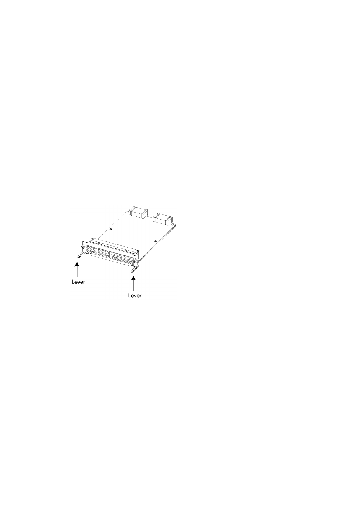
Safety Guide [IP8800/S6300]
damaged by the static electricity.
■ After removing an optional component, be sure to attach a blank panel.
• After removing an optional component, be sure to attach a blank panel. Using the device without the blank
panel attached, the air flow in the device cannot be maintained. In such a case, the temperature rise inside the
device may cause a failure.
■ Be sure to install the network interface module with the tray attached.
• Be sure to install the network interface module (NIF) with the tray attached to the device. If the NIF is inserted
without the tray attached, the connector of the NIF may not fit the connector of the switch, and the connectors
of both side may be damaged.
■ Attach an option component with care.
• Follow the following procedures to attach an option component. Otherwise, a problem may occur on the device.
1. Open the levers as the figure below.
2. With the levers in hands, push the component slowly into the device, to the point where the levers touch the device.
3. Use the levers to insert the component all the way. Move the levers slowly (taking more than one second) but not forcedly.
■ Before removing an optional component, loosen the screws completely.
• Use levers to remove the management and switching unit or network interface module. If screws are not
completely loosened, the optional component may be damaged when the levers are pressed down.
■ When carrying or packing an optional component, take care for handling.
• Take care not to handle the connector when carrying or packing optional components such as the management
and switching unit, network interface module, memory card, transceiver, and power supply. They must be
stored in antistatic bags when they are not in use.
■ Do not install the device in any place possibly reaching a high temperature.
• Be careful that the parts may be damaged if left in a place exposed to direct sunlight or close to a heating
apparatus.
xxxix

Safety Guide [IP8800/S6300]
■ Do not bring a TV or radio close to the device.
• Leaving a TV or radio close to the device can adversely influence to each other. If a TV or radio interferes the
device, remedy as follows:
1. Keep the device from the television or radio set as far away as possible.
2. Change the direction of the antenna for the television or radio set.
3. Use different outlets.
■ Keep the device away from a place with hydrogen sulfide or much salt.
• Places with hydrogen sulfide including hot spring resorts, and places with much salt including coasts may
shorten lifetime of the device.
■ Use air dusters with care.
• Choose an air duster designated to clean optical connectors. Other air dusters may get the end face of the
ferrule dirty.
• Avoid the nozzle or container of an air duster from touching the end face of the ferrule. Otherwise, the ferrule
may be damaged.
■ Handle the optical connector with care.
• Use the designated optical connector cleaner. Other optical connector cleaners may get the end face of the
ferrule dirty.
• Make sure of no problems on the head part of an optical connector cleaner, including attached fabric, grime,
and other foreign substances. Otherwise, the end face of the ferrule may be damaged.
• Do not push the optical connector forcedly to clean. Otherwise, the end face of the ferrule may be damaged.
• Rotate an optical connector cleaner (stick type) only in a clockwise direction. An optical connector cleaner
rotating clockwise as well as counterclockwise may damage the end face of the ferrule.
■ Maintenance and cleaning
• Wipe off the dirt on the device's outer surface with a dry, clean cloth or a well-wrung wet cloth containing water
or neutral cleanser. Do not apply volatile organic solvents or chemicals including benzine and thinner
pre-moistened cloths or insect killers, since they can deform, discolor or damage the device.
■ Long-term downtime
• For a long downtime, such as due to a long vacation or travel, be sure to unplug the power cable from the wall
outlet for safety. For a configuration using DC power supply, turn off the breaker on the power facility.
■ Discarding this device
• Discard the device according to the ordinance or rule of the local government or call the local waste material
handling facility.
xl

Safety Guide [IP8800/S3600] [IP8800/S2400]
■ Safety guide for the IP8800/S3600 and IP8800/S2400 series
• This document provides safety-related notices for use of the IP8800/S3600 and IP8800/S2400 series. To
utilize the functions of this device, read this document completely and carefully before using the device.
• Keep this document at hand after you read it, so that you can always refer it later.
• For any operation, follow the directions and procedures given by this document.
• Observe the cautions labeled on the device or those presented by this document. If you fail to do so, you
will cause damage to yourself or the device.
■ Symbols
• We have various symbols displayed on the IP8800/S3600 and IP8800/S2400 series and in the manuals to
guide you in using the IP8800/S3600 and IP8800/S2400 series correctly and safely without injuring
yourself and others, or damaging equipment assets. Below are the symbols and their meanings. Fully
understand the description and then proceed with reading the contents of the manual
If you ignore instructions preceded by this symbol, you could cause personal injury or
WARNING
death to yourself and others.
If you ignore instructions preceded by this symbol, you could cause personal injury to
CAUTION
CAUTION
NOTE
yourself and others, or serious damage to the device or surroundings.
If you ignore instructions preceded by this symbol, you could cause physical damage
to the device or surroundings.
A note is informational in nature. Unlike warning and caution notices, notes (for
prevention of malfunction, prevention of product minor damages) are not related to the
physical injury or damage to the device.
■ Operations and Handling
• Do not attempt to perform any operations not specifically described in "IP8800/S3600 IP8800/S2400 series
Hardware Installation Guide." In the event of a problem, turn off the power, unplug the power cable, and
contact a qualified service technician.
The instructions displayed on the device or in this manual are the results of our thorough consideration.
However, an unexpected situation may occur. For operations, not only follow the instructions but also
always be careful yourself.
■ Be careful in operation
• The instructions shown on the device or in this manual are the results of our thorough consideration.
However, an unexpected situation may occur. For operations, not only follow the instructions but also
always be careful with your judge.
xli

Safety Guide [IP8800/S3600] [IP8800/S2400]
WARNING
■ In case a failure should occur, power off the device immediately.
• In case a trouble such as smoke or unusual odor should occur or foreign materials or water should come
in to the device, power off the device immediately. If the device is used in a faulty state, fire disasters or
electric shock may be caused.
Actions to Be Taken When a Trouble Occurs
Device in Trouble Action to Be Taken
AC power supply model
AC power supply (PoE) model
DC power supply model Power off the device, and turn off the breaker on the power supply
Redundant power supply model Equipped with AC power
EPU Power off the EPU and unplug the power cable.
Equipped with no external
power unit (EPU)
Equipped with the external
power unit (EPU)
supplies
Equipped with DC power
supplies
Power off the device, and unplug the power cable.
Power off the device and power module, and unplug both power
cables.
equipment.
Power off all the power supplies mounted on the device, and unplug
the power cables.
Power off all the power supplies mounted on the device, and turn off
the breaker on the power supply equipment.
■ Do not put foreign materials in the device.
• Do not insert or drop metals or combustibles into the device through the intake/exhaust port. Fire disasters
or electric shock may be caused.
■ Do not press the RESET switch with a fragile tip, pin, or clip that may get stuck and
cannot be removed.
• Do not press the RESET switch with a fragile tip, pin, or clip that may get stuck and cannot be removed.
Fire disasters or electric shock may be caused.
■ Modification is not permissible.
• Device modification is not permissible. Fire disasters or electric shock may be caused.
■ Do not give a shock.
• In case the device is dropped or parts are damaged, power off the device, unplug the power cable out of
the outlet, and call the maintenance engineer. Otherwise, fire disasters or electric shock may be caused.
■ Do not put any material on the device.
• Do not put a metal such as pin, clip, or a container with water such as a vase or a flower pot on the device.
Fire disasters or electric shock may be caused.
xlii

Safety Guide [IP8800/S3600] [IP8800/S2400]
■ Do not use power not specified.
• Do not use a supply voltage not specified. Fire disasters or electric shock may be caused.
■ The current capacity supplied to the power distribution panel must be larger than the
operating current of the breaker.
• The current capacity supplied to the power distribution panel must be larger than the operating current of
the breaker. Otherwise, the breaker may not work in the event of a failure and cause fire disasters.
■ Grounding is required.
• For the AC power supply model, AC power supply (PoE) model, redundant power supply model (with AC
power supplies mounted), and external power unit (EPU), be sure to use a grounded outlet. If the power
supply is used without grounding, electric shock may be caused and failures may occur due to electric
noise.
• For the DC power supply model and redundant power supply model (with DC power supplies mounted),
be sure to use a grounding cable. If the power supply is used without grounding, electric shock may be
caused and failures may occur due to electric noise.
■ Installing/uninstalling of the DC power cable must be performed by the trained
engineer or maintenance personnel.
• Installing/uninstalling of the DC power cable must be performed by the trained engineer or maintenance
personnel. DC power cable is connected to the power supply via a terminal. Therefore, inadvertent
handling of the DC power cable may result in fire disasters or electric shock.
■ Before installing or removing a DC power cable, turn off the breaker on power supply
facilities.
• Before installing or removing a DC power cable, turn off the breaker on power supply facilities. Operation
with the breaker on may cause electric shock and fire disaster.
■ Attach insulation covers on the G terminal and -48V terminal of a DC power cable.
• Attach insulation covers on the G terminal and -48V terminal of a DC power cable (the side of which
connects to power supply facilities). Operation without insulation covers may cause electric shock.
■ Observe the specified margin of length when ripping the power cable sheath.
• When using the -48VDC power cable for the redundant power supply model, rip the power cable sheath
(on the device side) with the margin of 8 to 10 mm (0.3 to 0.4 in)..
If the margin is too small, loose connection or cable disconnection may be caused. On the other hand, too
large margin may cause conductor exposure, resulting in electric shock.
xliii

Safety Guide [IP8800/S3600] [IP8800/S2400]
■ Do not use the cable with the protection cap detached.
• Do not remove protection cap except when connecting the cable. Operating them with the protection cap
detached may cause an electric shock.
Since external power supply EPU-B has a high output power, the label below is attached near the external
power connector.
■ Handle the power cable with caution.
• Do not put a heavy material on the power cable or do not pull, bend, or modify the power cable. The power
cable will be damaged and fire disasters or electric shock may be caused. A heavy material may be
accidentally placed as a result of covering the cable with a floor carpet.
• Use the attached power cable or the power cable complying with the specifications. If any other cable is
used, fire disasters or electric shock may be caused. Do not use the attached power cable for other
purposes. If used, fire disasters or electric shock may be caused.
• If the power cable is degraded (e.g., wire cores exposed or broken), ask the service personnel for
replacement. Otherwise, fire disasters or electric shock may be caused.
• Check to see if no dust is deposited on the power plug. Insert the plug securely to the end so that shakiness
will not occur. If dust is deposited or connection is incomplete, fire disasters or electric shock may be
caused.
■ Do not use too many plugs at a single outlet.
• Do not use too many power plugs at a single outlet. Much loads on an electrical outlet may cause fire
disasters and the breaker gone off due to the exceeded in-use electric energy, affecting other components.
■ Before installing/uninstalling the power supply, unplug the power cable.
• Before installing/uninstalling the power supply, unplug the power cable from the power supply. With the
power cable connected, some circuit supplies power even though the power switch is turned OFF.
Therefore, installing/uninstalling the power supply with the power cable connected may cause a fire
disasters or electric shock.
■ Keep air dusters away from fire.
• If you use an air duster with combustible gas to clean the optical connector, keep away from fire. Otherwise,
fire disaster may occur.
xliv

Safety Guide [IP8800/S3600] [IP8800/S2400]
CAUTION
■ Do not place the device in an unstable location.
• If the device is being placed on a table, be sure to install it horizontally on a workbench or the like that can
sufficiently bear the weight of the device. If the device is placed on an unstable location such as a shaky
table or slope, the device may fall and drop and consequently personal injury may be caused.
• To mount the device on a rack, make sure that the device is placed in a stable location. If the device is
placed in an unstable location, the device may fall and drop and consequently personal injury may be
caused.
■ Do not remove the device cover.
• Do not remove the device cover. Electric shock may be caused. The label below is attached to the device.
■ Do not block the intake/exhaust port.
• Do not block the intake/exhaust port of the device. Blocking the intake/exhaust port keeps heat inside, and
fire disasters may be caused. Keep a space of at least 50 mm/2.0 in from the intake/exhaust port.
■ Do not bring hairs or any foreign materials close to the intake/exhaust port of the
device.
• The cooling fan unit is provided on the device. Do not put any material close to the intake/exhaust port. The
internal temperature rise may cause a failure. Do not put hair or any material close to the intake/exhaust
port. You may be caught and injured.
■ When moving the device, do not carry it by holding its handle of power supply, fan
unit, or power module.
• For the redundant power model, do not carry it by holding its handle of power supply or fan unit when
moving the device. The handle may be removed and the device may be dropped. As a result, personal
injury may be caused. Also, the device may be deformed and fire disasters or electric shock may be
caused.
• When moving the external power unit (EPU), do not carry it by holding its handle of power module. The
handle may be removed and the device may be dropped. As a result, personal injury may be caused. Also,
the device may be deformed and fire disasters or electric shock may be caused.
xlv

Safety Guide [IP8800/S3600] [IP8800/S2400]
Hold the cable plug of
AS power cable for
inserting and removing.
Hold the cable connector
of DC power cable for
inserting and removing.
■ Precaution on carrying the device
• When moving the device, power off the device, remove the power cable out of the outlet, remove all other
cables from the device, and then move the device. Otherwise, the device or cable may be deformed or
damaged. As a result, fire disasters or electric shock may be caused.
• When stacking the devices for transportation, put them into package boxes. Otherwise, the device may be
deformed or damaged. As a result, fire disasters or electric shock may be caused.
■ Do not roughly handle the power cable.
• Do not put the power cable close to the heating apparatus. The cable sheath may be melted and fire
disasters or electric shock may be caused.
• When inserting the AC power cable into the outlet or removing it from the outlet, be sure to hold the cable
plug. Pulling up the cable with the cable grasped, the wire can may be broken.
• When inserting the DC power cable into the outlet or removing it from the outlet, be sure to hold the cable
connector. Pulling up the cable with the cable grasped, the wire can be broken.
■ Shut down all the power to the device before powering off the device.
• For the AC power supply model and AC power supply (PoE) model using the external power unit (EPU),
the device cannot be powered off by turning off the power switch on the switch only. To power off, turn off
the power switches on the system and the power module.
• When the device has redundant power supply in the redundant power supply model, the device cannot be
powered off by turning off the power switch on only one of the power supply equipment. To power off, turn
xlvi

Safety Guide [IP8800/S3600] [IP8800/S2400]
Caution. Hot! (all sides)
off the power switches on all power supplies mounted on the device.
■ Do not touch the device directly if you have metal allergies.
• This device is coated with metals including zinc, nickel, and gold. If you have allergies to them, do not touch
the device directly to prevent getting dermatitis.
■ Be careful of the laser beams.
• The device uses the laser beams, which is invisible, clear and colorless. Do not peep in the optical
transceiver directly.
■ Do not touch a working (including immediately after stopping) SFP-T.
• A working (establishing a link) SFT-P can have up to 65 °C/140 °F in temperature. Do not touch it when
working or immediately after stopping to prevent getting burned.
• To remove an SFP-T, follow the following procedures. Otherwise, you may get burned.
• To remove an SFP-T without turning off the device, shut down the SFP slot, and remove the SFP-T five minutes later.
• To remove an SFP-T from the device turned off, power off the switch of the device, and remove the SFP-T five
minutes later.
• An SFP-T has the following label attached.
■ Do not install the device in a humid or dusty environment
• Do not install the device in a humid or dusty environment. Fire disasters or electric shock may be caused.
• Moving the device from a cold place to a warm place may form condensation on the surface or inside of
the device. If the device is operated immediately, a fire or electric shock can be caused. Thus, in this case,
leave the device as it is for several hours before starting operation.
■ Do not touch the inside of the device.
• Do not put your hand inadvertently inside the device. Mechanical parts may cause personal injury.
xlvii

Safety Guide [IP8800/S3600] [IP8800/S2400]
■ Do not ride, recline, or place a heavy loading on the device.
• Do not ride on or lean against the device. The device may be damaged. Alternatively, the device may lose
its balance and fall or drop. As a result, personal injury may be caused.
• Do not put a material weighing over 5 kg/11.1 lb on the device. The device may be damaged. Alternatively,
the device may lose its balance and fall or drop. As a result, personal injury may be caused.
■ Mount the fan unit on the empty slot not to be mounted with a power supply for the
redundant power supply model.
• Be sure to mount the fan unit on the empty slot not to be mounted with a power supply for the redundant
power supply model. Using the device without the fan unit, the temperature rise inside the device may
cause a failure. If foreign materials enter, a failure may be caused.
■ Attach a blank panel to the slot on the external power unit (EPU) where the power
module is not to be mounted.
• Be sure to attach a blank panel to the slot on the external power unit (EPU) where the power model is not
to be mounted. If the blank panel is not attached, mechanical parts may cause personal injury. If foreign
materials enter, a failure may be caused.
■ Cleaning
• Remove dust on and around the device on a regular basis. Device shutdown and fire disasters or electric
shock may be caused.
xlviii

Safety Guide [IP8800/S3600] [IP8800/S2400]
CAUTION
■ Do not install the device in any place possibly reaching a high temperature.
• Be careful that the parts may be damaged if left in a place exposed to direct sunlight or close to a heating
apparatus.
■ Do not bring a TV or radio close to the device.
• Leaving a TV or radio close to the device can adversely influence to each other. If the device interferes a
TV or radio, remedy as follows:
• Keep the device from the television or radio set as far away as possible.
• Change the direction of the antenna for the television or radio set.
• Use different outlets.
■ Keep the device away from a place with hydrogen sulfide or much salt.
• Places with hydrogen sulfide including hot spring resorts, and places with much salt including coasts may
shorten lifetime of the device.
■ Before installing/uninstalling the power cable, turn off the power switch.
• Before installing/uninstalling the power cables for AC power supply model, PoE AC power supply model,
or external power unit (EPU), turn off the power switch on the device.
• For the redundant power supply model, turn off the power switches on the power supplies before installing
or removing the power cable or cable connector.
• For the external power cable, turn off the power switch on the power module in advance.
■ When replacing the power supply or fan unit with the device powered on, complete
the task within the specified duration of time.
• When replacing the power supply or fan unit with the device powered on, complete the entire task from
removal to installation within three minutes. If it takes more than three minutes, a failure may occur due to
temperature rise inside the device.
xlix

Safety Guide [IP8800/S3600] [IP8800/S2400]
CAUTION
Before installing or
uninstalling the
power module, turn
off the power switch
■ Before installing/uninstalling the power module, turn off the power switch.
• Before installing/uninstalling the power module, turn off the power switch on the power module to be
installed or uninstalled. If operation is performed while the power switch on the power module is on, a
failure or device trouble may be caused. The label below is attached to the external power unit (EPU)
■ Before turning on the main power switch on the external power unit (EPU), turn off
the power switch on the power module.
• Before turning on the main power switch on the external power unit (EPU), turn off the power switch on the
every power module mounted.
■ Do not turn off the main power switch on the external power unit (EPU), while the
device is backed up by the EPU.
• When turning off the EPU main power switch, the backup power supply to the device is completely shut
down. If external power is supplied to the device, do not turn off the main power switch on the EPU.
■ Handle a memory card and a dummy memory card with care.
• Do not forcedly push or flip a (dummy) memory card to insert. Do not forcedly pull out a locked (dummy)
memory card to remove. Otherwise, the connector of the memory card slot may be damaged.
• Remove a (dummy) memory card to reposition the device. Moving the device may cause force against the
(dummy) memory card, which can damage the connector of the memory card slot.
■ Do not remove the memory card or disconnect power while the ACC LED is lit.
• Lighting of the ACC LED on the front panel indicates that the memory card is being accessed. Never
remove the memory card or disconnect power during access. The memory card may be damaged. Some
commands require a considerable time before completing access to the memory card after the entry of the
commands. Ensure that access is completed and then remove the memory card or disconnect power.
■ Do not attach a label or the like to the transceivers.
• The transceiver has a label indicating its manufacturer and that it is our standard supply. However, this label
is attached to the part that does not obstruct heat radiation from the transceiver or the mechanism
preventing slip-off from the cage. If a label or the like is attached to such an obstructing part, the transceiver
or the network interface module may be damaged.
■ When the ST1 LED is blinking in green, do not power off the device.
• Never disconnect the device power until the ST1 LED on the device front panel changes from blinking in
green into being lit. The device may fail.
l

Safety Guide [IP8800/S3600] [IP8800/S2400]
■ For carrying or packaging the device and optional component, use an antistatic wrist
strap.
• Use an antistatic wrist strap. If you handle the device without the antistatic wrist strap, the device can be
damaged by the static electricity.
■ When carrying or packing an optional component, take care for handling.
• Take care not to touch the connector when carrying or packing the transceiver, memory card, power supply,
fan unit, or power module. They must be stored in antistatic bags when they are not in use.
■ Use air dusters with care.
• Choose an air duster designated to clean optical connectors. Other air dusters may get the end face of the
ferrule dirty.
• Avoid the nozzle or container of an air duster from touching the end face of the ferrule. Otherwise, the
ferrule may be damaged.
■ Handle the optical connector with care.
• Use the designated optical connector cleaner. Other optical connector cleaners may get the end face of
the ferrule dirty.
• Make sure of no problems on the head part of an optical connector cleaner, including attached fabric,
grime, and other foreign substances. Otherwise, the end face of the ferrule may be damaged.
• Do not push the optical connector forcedly to clean. Otherwise, the end face of the ferrule may be
damaged.
• Rotate an optical connector cleaner (stick type) only in a clockwise direction. An optical connector cleaner
rotating clockwise as well as counterclockwise may damage the end face of the ferrule.
■ Maintenance and cleaning
• Wipe off the dirt on the device's outer surface with a dry, clean cloth or a well-wrung wet cloth containing
water or neutral cleanser. Do not apply volatile organic solvents or chemicals including benzine and thinner
pre-moistened cloths or insect killers, since they can deform, discolor or damage the device.
■ Long-term downtime
• For a long downtime, such as due to a long vacation or travel, be sure to unplug the power cable from the
wall outlet for safety. For a configuration using DC power supply, turn off the breaker of the power supply
equipment.
■ Discarding the device
• Discard the device according to the ordinance or rule of the local government or call the local waste
material handling facility.
li


1 Overview
This chapter outlines the failure analysis.
1.1 Failure Analysis Overview
1.2 System and Partial Failure Analysis Overview
1.3 Functional Failure Analysis Overview
1

1. Overview
1.1 Failure Analysis Overview
For any problems with IP8800/S6700, IP8800/S6600, IP8800/S6300, IP8800/S3600, and IP8800/S2400, refer to this
manual.
To visually check the system, follow the instructions in "1.2 System and Partial Failure Analysis Overview."
To login and check the system, follow the instructions in "1.3 Functional Failure Analysis Overview."
2

1. Overview
1.2 System and Partial Failure Analysis Overview
1.2.1 Failure Analysis for IP8800/S6700, IP8800/S6600, and IP8800/ S6300
If a failure occurs during operation and the system can be visually and directly checked, follow the procedure in
"2.1 Troubleshooting for IP8800/S6700, IP8800/S6600, and IP8800/S6300" to troubleshoot.
The device status is displayed on the basic control unit (BCU) for IP8800/S6700, the control and switching unit (CSU)
for IP8800/S6600, and management and switching unit (MSU) for IP8800/S6300. LED display of BCS/CSU/MSU is
shown in the "Table 1-1: LED Indications, Switches, and Connectors." Also, Front panel layout is shown in the "Figure
1-1: Example of Front Panel Layout."
For LEDs of optional components other than BCU/CSU/MSU shown as an example (BSU, NIF, power supply, and fan
unit) and the layout of front panel other than "Figure 1-1: Example of Front Panel Layout," see the manual "Hardware
Installation Guide."
Even though the system cannot be visually and directly checked, troubleshooting can be performed similarly by
checking system LEDs using the operation command from the remote operation terminal.
Table 1-1: LED Indications, Switches, and Connectors
No. Name Type Status Description
1STATUS
2SYSTEM
OPERATION
PANEL
3 ACC LED: Green Memory card status
4 SD CARD Connector SD card slot SD card slot
5RESET
6ACH
7 ACTIVE LED: Green BCU/CSU/MSU operation
8SYSTEM1
LED: Green/Orange/
Red
LCD and operation key System operation panel
Switch
(Non-locked)
Switch
(Non-locked)
LED: Green/Orange/
Red
Operation status of BCU/
CSU/MSU
System manual reset
switch
BCU/CSU/MSU
switchover switch
status
System status
Lit in green: Operational
Lit in orange: Self-diagnosis in progress
Blinking in green: Loading software
Lit in red: Failure detected
OFF: Power is OFF (BCU/CSU/MSU replaceable)
Displays the device information, operation
instructions, and failure information (for details, see
the manual "Configuration Settings")
Lit in green: Accessing the memory card (never detach
it).
OFF: Memory card in idle state (memory card setting/
removal permitted)
Pressing and holding for a second
: When the system fails
Pressing and holding for 5 seconds
: When the password is forgotten
When BCU/CSU/MSU is redundant, switchover
between the active system and standby system is
performed
Lit in green: Active system
OFF: Standby system
Lit in green: Operational
Lit in orange: System partial failure detected
Lit in red: System failure detected
.
*2*5
*2*3
*2*4
*1
3

1. Overview
No. Name Type Status Description
9SYSTEM2
10 AUX Connector AUX port RS-232C port for connecting operation terminal
11 CONSOLE Connector CONSOLE port RS-232C port for connecting operation terminal
12 MANAGEM
ENT
13 LINK LED: Green/Orange
14 T/R LED: Green
LED: Green/Orange/
Red
Connector MANAGEMENT port
Power mode status
MANAGEMENT port
operation status
MANAGEMENT port
operation status
*6*7
Lit in green: Power saving mode
Blinking in green: Power mode is being changed
OFF: Normal power mode
Lit in orange: Not supported
Lit in red: Not supported
10BASE-T/100BASE-TX Ethernet port for
connecting operation terminal
Lit in green: Link established
Lit in orange: Failure detected
OFF: Link failure
Lit in green: Sending/receiving packets
OFF: Not sending/receiving packets
*8
, or operation shut down
*1 BCU/CSU/MSU can be powered off by Inactivate operation from the system operation panel or by inputting the
command from the operation terminal.
*2 The switch is provided in an indented position on the panel surface. Use a thin tip screwdriver to press it.
*3 If the switch is not pressed and held for at least one second, reset may not occur.
*4 After the restart, the login password and system administrator password are not required. Therefore, care must be
taken to the restart using this method.
*5 Switchover is only performed when the ACH switch on the active BCU/CSU/MSU is pressed.
*6 When BSU is used in MSU(IP8800/S6300) and Software Ver11.1 or earlier, lights on the BSU always remain off.
*7 Only the active system of BSU/CSU indicates power mode status.
*8 The cable may have slipped off.
*9 Operation can be shut down by inputting a command.
*9
Figure 1-1: Example of Front Panel Layout
1.2.2 Failure Analysis for IP8800/S3600 and IP8800/S2400
If a failure occurs during operation and the system can be visually and directly checked, follow the procedure in
"2.2 Troubleshooting for IP8800/S3600 and IP8800/S2400" to troubleshoot.
For system LEDs of IP8800/S3630-24T2X and IP8800/S2430-24T2X see the figure below and "Table 1-2: LED
Indications, Switches, and Connectors."
Even though the system cannot be visually checked, troubleshooting can be performed similarly by checking system
LEDs using the operation command from the remote operation terminal.
4

1. Overview
Port 25 Port 26
Port 1
Port 4
Port 1
Port 2
Port 23
Port 24
For IP8800/S3600 and IP8800/S2400, the generic names of the models are as follows:
• AC power supply model: IP8800/S3640-24T, IP8800/S3630-24T, IP8800/S3630-24T2X, IP8800/S3630-24P,
IP8800/S2430-24T, IP8800/S2430-24T2X, IP8800/S2430-48T, IP8800/S2430-48T2X
• DC power supply model: IP8800/S3630-24TD, IP8800/S3630-24T2XD, IP8800/S2430-24TD, IP8800/
S2430-24T2XD, IP8800/S2430-48TD
• Redundant power supply model: IP8800/S3640-24TW, IP8800/S3640-24T2XW, IP8800/S3640-48TW, IP8800/
S3640-48T2XW, IP8800/S3640-24SW, IP8800/S3640-24S2XW, IP8800/S3630-48TW, IP8800/S3630-48T2XW,
IP8800/S3630-24S2XW
Figure 1-2: Front Panel Layout
Table 1-2: LED Indications, Switches, and Connectors
No. Name Type Function Description
1 PWR LED: Green Indicates the power ON/OFF status.
2 ST1 LED: Green/Red Indicates the system status.
3 ST2 LED: Green Always OFF because it is not supported.
4 MC Connector Memory card slot Memory card slot
5 ACC LED: Green Indicates the status of memory card.
6CONSOLEConnector CONSOLE port RS-232C port for connecting a console terminal
7LINK
8 T/R LED: Green Lit in green: Sending/receiving frames
9LINK
10 T/R LED: Green Blinking in green: Sending/receiving frames
LED: Green/
Orange
LED: Green/
Orange
Indicates the operation status of
Ethernet port in SFP module slot.
Indicates the operation status of
Ethernet port in XFP module slot.
Lit in green: Power ON
OFF: Power OFF or power failure
Lit in green: Operational
Blinking in green: Starting up (starting up)
Blinking in red: Partial failure of the device
Lit in red: Fatal system failure (operation cannot be
continued)
OFF: Power OFF or power failure
ON: Accessing the memory card (the memory card is
not detachable)
OFF: Memory card is idle (detachable/attachable)
Lit in green: Link established
Lit in orange: Line failure detected
OFF: If ST1 LED is lit in green, the link failed or is
blocked.
Lit in green: Link established
Lit in orange: Line failure detected
OFF: If ST1 LED is lit in green, the link failed or is
blocked
5

1. Overview
No. Name Type Function Description
11 1-24
12 RESET
LED: Green/
Orange
Switch
(Non-locked)
Indicates the operation status of 10/
100/1000BASE-T Ethernet port.
System manual reset switch Restarts the system.
Lit in green: Link established
Blinking in green: Link established and frames being
sent/received
Lit in orange: Line failure detected
OFF: If ST1 LED is lit in green, the link failed or is
blocked
Note: Figure 1-2 and Table 1-2 show a typical system. For more details on each system, see "Hardware Installation
Guide."
6

1. Overview
1.3 Functional Failure Analysis Overview
The overview of functional failure analysis for this system is shown in the table below.
Some communication failure in the lower layer may cause the communication failure in the upper layer, check the
items in the lower layer as well.
Table 1-3: Functional Failure Status and Reference
Item Subitem Reference
Forgot login password Forgot login user password 3.1.1 Forgot the Login User Password
Forgot system administrator password 3.1.2 Forgot the System Administrator Password
Problems on MC "MC:--------" is displayed 3.2.1 "MC:--------" is displayed by entering the show
system command or the show mc command
"MC not found." is displayed 3.2.2 "MC not found" is displayed when MC is
accessed
Problems on operation terminal Console input/display disabled 3.3.1 Unable to Input/Display from the Console
Remote login disabled 3.3.2 Login from the Remote Operation Terminal Is
Login authentication disabled 3.3.4 Command Authorization Using RADIUS/
Command acceptance disabled 3.3.4 Command Authorization Using RADIUS/
Network interface communication
failure
Layer 2 network communication
failure
IPv4 network communication
failure
Ethernet port communication failure 3.4.1 Ethernet Port Cannot Be Connected
BSU communication failure
[IP8800/S6700]
10BASE-T/100BASE-TX/1000BASE-T
communication failure
1000BASE-X communication failure 3.4.4 Actions against Troubles on 1000BASE-X
10GBASE-R communication failure 3.4.5 Actions against Troubles on 10GBASE-R
Communication failure while PoE is
functioning
Link aggregation failure 3.4.7 Communication Failure on Using Link
VLAN failure 3.5.1 Layer 2 Communication by VLAN Is Disabled
Spanning tree failure 3.5.2 Failures on Using Spanning Tree
Ring Protocol failure 3.5.3 Failures on Using Ring Protocol
IGMP snooping disabled 3.5.4 Multicast Relay by IGMP snooping Is Disabled
MLD snooping disabled 3.5.5 Multicast Relay by MLD snooping Is Disabled
Communication disabled 3.6.1 Communication Is Disabled or Is Disconnected
DHCP disabled 3.6.2 IP Addresses Cannot Be Assigned Using DHCP
Dynamic DNS disabled 3.6.3 DynamicDNS Cooperation in DHCP Function Is
Correctly
Failed
TACACS+ Is Disabled
TACACS+ Is Disabled
3.4.2 Communication Failure in Basic Switching Unit
BSU/PSP [IP8800/S6700]
3.4.3 Actions against Troubles on 10BASE-T/
100BASE-TX/1000BASE-T
3.4.6 Communication Failure on Using PoE
Aggregation
Function
Disabled
7

1. Overview
Item Subitem Reference
IPv4 unicast routing
communication failure
IPv4 multicast routing
communication failure
IPv6 network communication
failure
IPv6 multicast routing
communication failure
IPv6 multicast routing
communication failure
Layer 2 authentication
communication failure
GSRP failure - 3.13.1 GSRP Communication Failures
IPv4 VRRP failure - 3.13.2 Communication with VRRP Configuration in
IPv6 VRRP failure - 3.13.3 Communication with VRRP Configuration in
SNMP communication failure MIB acquisition disabled 3.14.1 MIBs Cannot Be Obtained from SNMP
sFlow statistics failure sFlow packet does not reach 3.15.1 sFlow Packets Do Not Reach Collector
No RIP information 3.7.1 No RIP Routing Information Exists
No OSPF information 3.7.2 No OSPF Routing Information Exists
No BGP4 information 3.7.3 No BGP4 Routing Information Exists
No VRF information 3.7.4 No Routing Information Exist [OP-NPAR]
Communication disabled on PIM-SM
network
Data double-relayed on PIM-SM network 3.8.2 Multicast Data Is Double-relayed on IPv4
Communication disabled on PIM-SSM
network
Data double-relayed on PIM-SSM network 3.8.4 Multicast Data Is Double-relayed on IPv4
Communication failure of VRF 3.8.5 IPv4 Multicast Communication Failure In VRF
Communication disabled 3.9.1 Communication Is Disabled or Is Disconnected
DHCP trouble 3.9.2 IPv6 DHCP Troubleshooting
No RIPng information 3.10.1 No RIPng Routing Information Exists
No OSPFv3 information 3.10.2 No OSPFv3 Routing Information Exists
No BGP4+ information 3.10.3 No BGP4+ Routing Information Exists
Communication disabled on PIM-SM
network
Data double-relayed on PIM-SM network 3.11.2 Multicast Data Is Double-relayed on IPv6
Communication disabled on PIM-SSM
network
Data double-relayed on PIM-SSM network 3.11.4 Multicast Data Is Double-relayed on IPv6
Authentication failed in IEEE802.1X 3.12.1 Communication Failure on Using IEEE 802.1X
Authentication failed in Web
authentication
Authentication failed in MAC
authentication
Authentication failed in authentication
VLAN
Trap receiving disabled 3.14.2 Traps Cannot Be Received by SNMP Manager
Flow sample does not reach 3.15.2 Flow Sample Does Not Reach Collector
Counter sample does not reach 3.15.3 Counter Sample Does Not Reach Collector
3.8.1 Communication on IPv4 PIM-SM Network Is
Disabled
PIM-SM Network
3.8.3 Communication on IPv4 PIM-SSM Network Is
Disabled
PIM-SSM Network
[OP-NPAR]
3.11.1 Communication on IPv6 PIM-SM Network Is
Disabled
PIM-SM Network
3.11.3 Communication on IPv6 PIM-SSM Network Is
Disabled
PIM-SSM Network
3.12.2 Communication Failure on Using Web
Authentication
3.12.3 Communication Failure on Using MAC
Authentication
3.12.4 Communication Failure on Using
Authentication VLAN [OP-VAA]
IPv4 Network Is Disabled
IPv6 Network Is Disabled
Manager
8

Item Subitem Reference
1. Overview
Neighboring system information
cannot be acquired by LLDP
function
Neighboring system information
cannot be acquired by OADP
function
Communication failure in NTP - 3.17.1 Time Synchronization by NTP Is Disabled
Failure when using IEEE802.3ah/
UDLD function
Problems on redundant
configuration of basic control unit
(BCU)/control and switching unit
(CSU)/management and switching
unit (MSU)
[IP8800/S6700] [IP8800/
S6600] [IP8800/S6300]
Problems on redundant
configuration of basic switching
unit (BSU) [IP8800/S6700]
Problem on using power saving
function
Communication failure due to
discard of packets
Communication failure due to
resource shortage
[IP8800/S6700] [IP8800/
S6600] [IP8800/S6300]
Others - Re-check the setting according to "Configuration
- 3.16.1 Unable to Obtain Neighboring System
Information via LLDP Function
- 3.16.2 Unable to Obtain Neighboring System
Information via OADP Function
Port becomes inactive 3.18.1 Port Becomes Inactive Due to IEEE802.3ah/
- 3.19.1 Active System Switchover Is Disabled
BSU switchover disabled 3.20.1 Active BSU Switchover Is Disabled
Schedule is disabled
[IP8800/S6700] [IP8800/S6600]
- 3.23.1 Checking Filtering/QoS Setting Information
The volume of MAC address table used
exceeds the accommodating condition.
The volume of VLAN identification table
used exceeds the accommodating
condition.
Resource shortage of shared memory
UDLD Function
3.21.1 Schedule Is Disabled [IP8800/S6700]
[IP8800/S6600]
4.1 MAC Address Table Resource Shortage
4.2 When Resource Shortage of VLAN Identification
Table Occurs
4.3 When Resource Shortage Occurs in Shared
Memory
Settings."
9


2 Troubleshooting System Failures
This chapter explains how to deal with the problems on the system.
2.1 Troubleshooting for IP8800/S6700, IP8800/S6600, and IP8800/S6300
2.2 Troubleshooting for IP8800/S3600 and IP8800/S2400
11

2. Troubleshooting System Failures
2.1 Troubleshooting for IP8800/S6700, IP8800/S6600, and IP8800/S6300
2.1.1 Troubleshooting Procedure on System Failures
Follow the procedure below when the system failed.
Table 2-1: Troubleshooting System Failures
No. Failure Action
1
• Fume generated from the system
• Unusual odor occurs from the system
• Unusual sound occurs from the system
2 login prompt is not displayed
3 All LEDs on BCU/MSU are OFF
4 BCU/CSU/MSU SYSTEM1 LED lit in red or
orange
Execute the steps below immediately.
1. Power off the system.
2. When the power cable is fastened by the slip-off preventive clamp,
remove it from the power cable.
3. For AC power supply, unplug the power cable.
4. For DC power supply, turn off the breaker of power distribution panel
connected to the system.
Shut down operation as described above and then contact the local sales
office.
1. When MC is inserted, first remove the MC then reboot the system by
turning it off and on.
2. When MC is not inserted, reboot the system by turning it off and on.
3. If the same problem still persists after system reboot, replace BCU/CSU/
MSU.
1. Check LED on the power supply and follow the steps below.
(1) If ALARM LED is lit in red on the power supply, replace the power
supply with a new one.
(2) If both POWER LED and ALARM LED are OFF on the power
supply, implement "Table 2-2: Power Failure Check Items." If the
problem is not settled, replace the power supply with LED turned off.
2. If all power supplies are running normally, replace BCU/CSU/MSU.
1. If an error message is output to the system operation panel, take the
action against the corresponding error message in manual "Message Log
Reference."
2. If no error message is output, replace BCU, BSU, CSU, MSU or NIF on
which STATUS LED is lit in red.
12

2. Troubleshooting System Failures
No. Failure Action
5 Error message output to the system operation
panel
6 STATUS LED on BCU/CSU/MSU is lit in red,
other LEDs are OFF, and no message on the
system operation panel
Take the action against the corresponding error message in the manual
"Message Log Reference."
1. Check the single/redundant configuration of BCU/CSU/MSU.
(1) For the single configuration, follow the step 3 and later.
(2) For the redundant configuration, follow the step 2 and later.
2. Check the active/standby state of BCU/CSU/MSU.
(1) If the failure occurs only in one system, replace the BCU/CSU/MSU.
You do not have to follow the step 3 and later.
(2) If the failure occurs in both systems, follow the step 3 and later.
3. Check the LED on the power supply.
(1) If ALARM LED is lit in red on the power supply, replace the power
supply with a new one.
(2) If both POWER LED and ALARM LED are OFF on the power
supply, implement "Table 2-2: Power Failure Check Items" If the
problem is not settled, replace the power supply with LED turned off.
(3) If all power supplies are running normally, leave those power supplies
as is.
4. Turn off all power supplies installed on the system.
5. At least two seconds elapse, turn on all power supplies installed on the
system.
(1) If this failure occurs on BCU/CSU/MSU, replace the BCU/CSU/
MSU.
Table 2-2: Power Failure Check Items
No. Failure Action
1 Power switch on the power supply is OFF Turn on the power switch.
2
• Power cable is unplugged
• Power cable is not firmly connected to the system
• Power cable is not securely fastened by the slip-off
preventive clamp
3 Power supply is not securely mounted but loose Follow the steps below.
4 Measured input power is out of the range below.
100VAC: 90 to 132VAC
200VAC: 180 to 264VAC
-48VDC: -40.5 to -57VDC
Note: Implement this matter only if input power can
be measured.
Follow the steps below.
1. Turn off the power switch.
2. For DC power supply, turn off the breaker of power distribution
panel connected to the system.
3. Connect the power cable correctly.
4. If the power cable can be fastened by the slip-off preventive clamp,
fasten the power cable using it.
5. For DC power supply, turn on the breaker of power distribution
panel connected to the system.
6. Turn on the power switch.
1. Turn off the power switch.
2. For DC power supply, turn off the breaker of power distribution
panel connected to the system.
3. When the power cable is fastened by the slip-off preventive clamp,
remove it from the power cable.
4. Remove the power cable.
5. Remove the power supply and insert it securely.
6. Attach the power cable.
7. If the power cable can be fastened by the slip-off preventive clamp,
fasten the power cable using it.
8. For DC power supply, turn on the breaker of power distribution
panel connected to the system.
9. Turn on the power switch.
Contact the person in charge of the power facility and ask him/her to
take the action for input power.
13

2. Troubleshooting System Failures
2.1.2 Replacement Method of Optional Components
The optional component replacement procedures are described in "Hardware Installation Guide." Follow the
procedures described in the manual.
14

2. Troubleshooting System Failures
2.2 Troubleshooting for IP8800/S3600 and IP8800/ S2400
2.2.1 Troubleshooting Procedure on System Failures
Follow the procedure below when the system failed.
Table 2-3: Troubleshooting System Failures
No. Failure Action
1
• Fume generated from the system
• Unusual odor occurs from the system
• Unusual sound occurs from the system
2 login prompt is not displayed
3 PWR LED on the system is OFF Follow the steps below to take the action.
4 ST1 LED on the system is lit in red A failure occurred or the system was powered on after it had remained
Execute the steps below immediately.
1. Power off the system.
2. Remove the power cable of the system.
After the above steps, replace the system.
1. When MC is inserted, first remove the MC then reboot the system by
turning it off and on.
2. When MC is not inserted, reboot the system by turning it off and on.
3. If the same problem still persists after system reboot, replace the
system.
1. Follow the steps in "Table 2-4: Isolating Power Supply Failure"
2. For the redundant power model, replace the power supply that has
failed. The faulty power supply is in one of the states below.
(a) POWER LED is off.
(b) ALM1 LED is lit in red.
(c) ALM2 LED is lit in red.
3. If 1 and 2 are not applicable, restart the system and confirm that the
environment is free from troubles.
(1) Turn off the power switch on the system (or power supply for the
redundant power model) and turn it on again to restart the system.
(2) If the system can be restarted, execute the show logging
command to view the failure information.
>show logging | grep ERR
(3) If a message "Caution, High temperature" exists in the retrieved
failure information, the operating environment may have caused the
failure. Request the system administrator to improve the
environment.
(4) If the system cannot be restarted by procedure (1) above and no
failure information exists in procedure (3) above or message
"Caution, High temperature" does not exist, the system may have
failed. Replace the system.
powered off for a long time (at least one month).
1. If you do not turn on the power of the system for a long time (one month
or more), reboot the system by turning it off and on.
2. In the case of other than the previous case, a failure might occur in the
system. Replace the system.
15

2. Troubleshooting System Failures
No. Failure Action
5
• ST1 LED on the system is blinking in red
• LINK LED (10GBASE-R port and
1000BASE-X port) and 1-48 LED (10/100/
1000BASE-T port) on each port of the system
are lit in orange or OFF
6 "EPU:Disconnect" is displayed for the system
management command although LEDs on the
system and external power unit are normal
System or line has failed.
1. For the redundant power supply model, check the states of the power
supplies and fan unit. Replace them if they have failed.
- If ALM LED on the fan unit is lit in red, replace the fan unit.
- If ALM1 LED or ALM2 LED or the power supply is lit in red, replace
the power supply.
- If POWER LED on the power supply is off, take the action against
power failure according to "Table 2-4: Isolating Power Supply
Failure." If POWER LED is still off after the action is taken, replace
the power supply.
2. For cases other than 1 above, refer to the error message and take the
action against the failure. Execute the show logging command to
check the failure information and take the action.
>show logging | grep ERR
3. For the failure on the external power unit, refer to "2.2.2 Isolating
Failures on External Power Unit" to isolate the failure.
Check the cable interconnecting the system and EPU. If the cable has
slipped off, restart the system as described below.
1. Power off the system.
2. Reconnect the cable that has slipped off.
3. Power off the system.
Table 2-4: Isolating Power Supply Failure
No. Failure Action
1 Power switch on the system (or power supply for the
redundant power model) is OFF
2 Power cable has slipped off or is loose Follow the steps below.
3 For the redundant power supply model, the power
supply is not securely mounted but loose
4 Measured input power is out of the range below.
100VAC: 90 to 127VAC
200VAC: 180 to 254VAC
-48VDC: -40.5 to -57VDC
Note: Implement this matter only if input power can be
measured.
Turn on the power switch.
1. Turn off the power switch.
2. Connect the power cable correctly.
3. Turn on the power switch.
Follow the steps below.
1. Turn off the power switch.
2. Insert the power supply correctly.
3. Turn on the power switch.
Contact the person in charge of the power facility and ask him/her to
take the action for input power.
16

2.2.2 Isolating Failures on External Power Unit
If the external power unit fails, follow the steps below to isolate the failure.
Table 2-5: Isolating Failures on External Power Unit
No. Failure Action
2. Troubleshooting System Failures
1 POWER LED on the external power unit is lit in
green
2 POWER LED on the external power unit is OFF Follow the steps in "Table 2-6: Isolating Failures on External Power
Check LED on the power module mounted on the external power unit
and identify the power module that is not normally running. If the power
module is normally running, the states below are provided.
• EPU-A:
DC-OK: Lit in green, DC-ALM: OFF
• EPU-B:
DC-OK: Lit in green, DC-FAIL: OFF, AC-OK: Lit in green
For the power module that is not normally running, implement "Tabl e
2-7: Isolating Failures on Power Module."
Unit (Main Body)."
Table 2-6: Isolating Failures on External Power Unit (Main Body)
No. Failure Action
1 Power switch on the external power unit is OFF Turn on the power switch.
2 Power cable of the external power unit is not
correctly connected to the system
3 Input power to the external power unit is out of the
range below
(AC power supply: 90 to 132V)
4 Other than 1 to 3 above Replace the external power unit.
1. Turn off the power switch.
2. Connect the power cable correctly.
3. Turn on the power switch.
Ask the system administrator to take the action because of the failure on
the power supply facility (i.e. not the failure on this system).
Table 2-7: Isolating Failures on Power Module
No. Failure Action
1 Power switch on the power module is OFF Turn on the power switch on the power module.
2 Power cable of the power module is not correctly
connected to the system
3 Power module is not correctly mounted on the
external power unit
4 Other than 1 to 3 above Replace the power module.
1. Turn off the power switch on the power module.
2. Connect the power cable correctly.
3. Turn on the power switch on the power module.
1. Turn off the power switch.
2. Mount the power module correctly.
3. Turn on the power switch.
17

2. Troubleshooting System Failures
2.2.3 Replacement Method of System and Optional Components
The replacement procedures for optional components are described in "Hardware Installation Guide." Follow the
procedures described in the manual.
18

3 Troubleshooting Functional Failures
in Operation
This chapter describes actions to be taken when the system does not operate normally
or the communication is not possible.
3.1 Problems on Login Password
3.2 Problems on MC
3.3 Problems on Operation Terminal
3.4 Network Interface Communication Failure
3.5 Layer 2 Network Communication Failure
3.6 IPv4 Network Communication Failure
3.7 IPv4 Unicast Routing Communication Failure
3.8 IPv4 Multicast Routing Communication Failure
3.9 IPv6 Network Communication Failure
3.10 IPv6 Unicast Routing Communication Failure
3.11 IPv6 Multicast Routing Communication Failure
3.12 Layer 2 Authentication Communication Failure
3.13 Communication Failure on High-reliability Function
3.14 SNMP Communication Failure
3.15 Troubleshooting of sFlow Statistics (Flow Statistics) Function
3.16 Communication Failures on Neighboring System Managing Function
3.17 NTP Communication Failure
3.18 Communication Failure on IEEE802.3ah/UDLD Function
3.19 Problems on Redundant Configuration of Basic Control Unit (BCU)/Control and Switching
Unit (CSU)/Management and Switching Unit (MSU) [IP8800/S6700] [IP8800/S6600]
[IP8800/S6300]
19

3. Troubleshooting Functional Failures in Operation
3.20 Problems on Redundant Configuration of Basic Switching Unit (BSU) [IP8800/S6700]
3.23 Communication Failure Caused by Settings of Filtering/QoS
20

3. Troubleshooting Functional Failures in Operation
3.1 Problems on Login Password
3.1.1 Forgot the Login User Password
If you forgot the login user password and cannot login to the system during operation, follow the procedure below.
1. Reporting to the system administrator
First, consult the system administrator. However, if there is no login user eligible for the administrator (e.g., there is
no other login user), perform a default restart and set a password again.
Default restart
Press and hold the reset switch on the system for five or more seconds.
Since security check using a password is not performed, special care must be taken when doing default restart.
The password setting is enabled after starting the system.
2. Changing the password
When a password change is requested, the system administrator must change it and inform all the target login users
of the change (use the password command to change a password, or the clear password command to simply
delete it).
Figure 3-1: Changing Login User Password by System Administrator
# password user1
Changing local password for user1.
New password:
Retype new password:
#
3.1.2 Forgot the System Administrator Password
If all the login users with the system administrator privilege forgot the system administrator password and they cannot
enter the system administrator mode, perform the default restart to set up a password again.
Default restart
Press and hold the reset switch on the system for five or more seconds.
Since security check using a password is not performed, special care must be taken when doing default restart. The
password setting is valid after restarting the system.
21

3. Troubleshooting Functional Failures in Operation
3.2 Problems on MC
3.2.1 "MC:--------" is displayed by entering the show system command or the show mc command
When "MC:--------" is displayed by entering the show system command or the show mc command, follow the
instruction in "Table 3-1: Problems and Actions When "MC:--------" is displayed"
Table 3-1: Problems and Actions When "MC:--------" is displayed
No. Failure Troubleshooting Steps
1 Check to see ACC LED. When ACC LED is lit in green, it indicates other process might be accessing to MC. After
the ACC LED lights off, execute the command again. If the ACC LED is not lit in green,
follow the instructions on No.2 and later.
2 Remove the MC then insert it. After removing and inserting MC, execute the command again.
Confirm that no dust is attached on the MC or the memory card. If dust is adhere to them,
clean it with a dry cloth then insert the MC.
If a symptom still occurs after you have removed and inserted the MC for several times,
follow the instructions on No.3.
3 Replace the MC with a new one. Replace the MC then execute the command again.
If a fault still occurs after the MC has been replaced, memory slot card might be broken. In
this case, replace the BCU [IP8800/S6700], the CSU [IP8800/S6600], the MSU
[IP8800/S6300], the system [IP8800/S3600], or the system [IP8800/S2400].
3.2.2 "MC not found" is displayed when MC is accessed
When "MC not found" is displayed after the command for accessing to MC has been executed, follow the instruction in
"Table 3-2: Problems and Actions When "MC not found" is displayed."
Table 3-2: Problems and Actions When "MC not found" is displayed
No. Failure Troubleshooting Steps
1 Check to see ACC LED. When ACC LED is lit in green, it indicates other process might be accessing to MC. After
2 Remove the MC then insert it. After removing and inserting MC, execute the command again.
3 Replace the MC with a new one. Replace the MC then execute the command again. If a fault still occurs after the MC has
the ACC LED lights off, execute the command again. If ACC LED is not lit in green, follow
the instructions on No.2 and later.
Check to see that any dust is not attached on the MC or the memory card. If dust is adhere
to them, clean it with a dry cloth then insert the MC.
If a symptom still occurs after you have removed and inserted the MC for several times,
follow the instructions on No.3.
been replaced, memory slot card might be broken. In this case, replace the BCU [IP8800/
S6700], the CSU [IP8800/S6600], the MSU [IP8800/S6300], or the system [IP8800/
S3600] [IP8800/S2400].
22

3. Troubleshooting Functional Failures in Operation
3.3 Problems on Operation Terminal
3.3.1 Unable to Input/Display from the Console Correctly
When there is a problem connecting to the console, follow the instruction in "Table 3-3: Problems and Actions When
Connecting to Console."
When there is a problem connecting to the modem, follow the instruction in "Table 3-4: Problems and Actions When
Connecting to Modem." Also, see the manual provided with the modem.
Table 3-3: Problems and Actions When Connecting to Console
No. Failure Troubleshooting Steps
1 Nothing is displayed on the
screen.
2 You cannot enter any key. Determine the cause by following the steps below:
3 Abnormal characters are
displayed upon login.
4 Abnormal characters appears
while entering user name.
5 Login is disabled. Confirm that the login prompt appears on the screen. If it is not the case, starting up the
6 Abnormal characters appear and
command entry is rejected when
the communication rate of the
communication software is
changed after login.
7 Abnormal characters appear
upon login with HyperTerminal.
8 Item names and contents are not
displayed in line.
Determine the cause by following the steps below:
1. Check if the ST1 LED on the front panel of the system lights in green. If it is not, see
"1.2 System and Partial Failure Analysis Overview."
2. Check to see if the cable is connected correctly.
3. Confirm that RS232C cross cable is used.
4. Confirm that communication software settings, including port number, communication
rate, data length, parity bit, stop bit, flow control are set as follows:
Communication rate: 9600 bps (or a custom value)
Data length: 8 bits
Parity bit: None
Stop bit: 1 bit
Flow control: None
1. Data sending/receiving may be interrupted by the XON/XOFF flow control. Restart the
data sending/receiving (press [Q] key with the [Ctrl] key pressed). If the problem
continues, follow the instructions on No.2 and later.
2. Check to see if the communication software is configured properly.
3. The screen may be suspended by [Ctrl]+[S]. Press any key.
Negotiation with the communication software may have failed. Check the communication
rate of the communication software as described below.
1. If the communication rate for the CONSOLE (RS232C) has not been set up using
configuration command line console 0, check to see if the communication rate is
set to 9600 bps in the communication software.
2. If the communication rate for the CONSOLE (RS232C) is set to 1200, 2400, 4800, 9600
or 19200 bps using configuration command line console 0, confirm that the
communication rate in the communication software has been correctly set.
Communication rate for the CONSOLE (RS232C) may have been changed. See No. 3.
system is on the way. Wait for a while.
If the communication rate of the communication software is changed after login, normal
display is not achieved. Reset the communication rate of the communication software to the
original setting.
Negotiation with the communication software may have failed. See No. 3. Issue a break
signal using [Alt]+[B]. Depending on the communication rate in HyperTerminal, login
screen may not appear until you issue several break signals.
The size of information might be too large to display within one line. Change the screen size
by setting the communication software and increase the number of characters that can be
displayed in one line.
23

3. Troubleshooting Functional Failures in Operation
Table 3-4: Problems and Actions When Connecting to Modem
No. Failure Troubleshooting Steps
1 Automatic termination to the modem is
disabled.
2 Abnormal characters are displayed upon
login.
3 Line is busy and cannot be connected by
redialing after disconnection.
4 Line cannot be reconnected after line failure. When the line is disconnected due to a failure, reconnection may be disabled
5 Line cannot be reconnected after
disconnection.
Check the following.
• Cable is connected properly.
• Modem is powered on.
• Telephone number is correct.
• Settings of the modem are correct.
• Line can be connected by connecting the modem to two terminals and
dialing.
Determine the cause by following the steps below:
1. Set the baud rate of the modem to 9600 bps.
2. If the modem supports communication standard V90, K56flex, x2, or later,
set the modem so that it is connected via V.34 communication method or
below.
Termination may be disabled for several seconds after disconnection of the line.
See the manual provided with the modem.
for up to 120 seconds. If you want to connect the line immediately, login via
another method, and use the killuser command to apply forced logout to the
user who connected AUX by dial-up IP connection.
When dial-up IP connection is disconnected, it might take time to reconnect the
line. In this case, wait for approximately 30 seconds then reconnect the line.
3.3.2 Login from the Remote Operation Terminal Is Failed
When connecting to the remote operation terminal fails, take actions in the following table.
Table 3-5: Problems and Actions When Connecting Remote Operation Terminal
No. Symptom Action to Be Taken or Reference
1 Remote connection rejected. Determine the cause by following the steps below:
1. To make sure the route for the remote connection has been established, execute the
ping command from a PC or workstation.
2. After the message indicating the connection has been established is displayed, if it needs
much time to display the prompt, communication with the DNS server may possibly be
disabled. (If this is the case, it takes approximately five minutes until the prompt is
displayed, which is a typical value and usually depends on network conditions.)
2 Login rejected. Determine the cause by following the steps below:
1. Check to see if the terminal used has the IP or IPv6 address allowed by the access list
for the configuration command line vty mode. Furthermore, confirm that deny has
not been set for the IP or IPv6 address on the access list in the configuration command
(for details, see the manual "Configuration Commands, Vol. 1").
2. Confirm that maximum number of login users has not been exceeded (for details, see
the manual "Configuration Settings").
If reachability from the remote operation terminal to this system is lost when the
maximum number of users have logged in and then the reachability is recovered, a
remote operation terminal cannot log in to the system until the time of TCP protocol
timeout elapses to clear the session. The time of TCP protocol timeout is approximately
10 minutes although it depends on the states of the remote operation terminal and
network.
3. Check to see if protocols restricted by the configuration command transport
input in line vty mode are not being used. For more details, see the manual
"Configuration Commands."
24

3. Troubleshooting Functional Failures in Operation
No. Symptom Action to Be Taken or Reference
3 Key entry rejected. Determine the cause by following the steps below:
1. Data sending/receiving may be interrupted by the XON/XOFF flow control. Restart the
data sending/receiving (press [Q] key with the [Ctrl] key pressed). If key entry is still
disabled, check No. 2 or later.
2. Check to see if the communication software is configured properly.
3. The screen may be suspended by [Ctrl]+[S]. Press any key.
4 Some users remain in the login
state.
Wait for automatic logout or log in again and use the killuser command to delete users
in the login state. If editing the configuration is on the way, the possibly changed
configuration information has not been saved. Log in again and enter the configuration mode
to save the change and exit from the editing.
3.3.3 Login Authentication Using RADIUS/TACACS+ Is Disabled
If login authentication using RADIUS/TACACS+ is failed, check the following:
1. Communication with the RADIUS/TACACS+ server
Use the ping command to see if communication from this system to the RADIUS/TACACS+ server is achieved. If it
is not possible to communicate with the server, see "3.6.1 Communication Is Disabled or Is Disconnected." If a local
address has been defined in configuration, check the connectivity between this system and RADIUS/ TACACS+
servers by issuing ping from the local address.
2. Setting timeout value and retry count
For the RADIUS authentication, you can use configuration commands radius-server host,
radius-server retransmit, and radius-server timeout to determine the maximum value of the
timeout, which determines that communication between this system and the RADIUS server is faulty. This value is
calculated by <set timeout value (sec.)> × <set retry count> × <set number of RADIUS servers>.
For the TACACS+ authentication, you can use configuration commands tacacs-server host and
tacacs-server timeout to determine the mazimum value of the timeout, which determines that
communication between this system and TACACS+ server is faulty. This value is calculated by <set timeout value
(sec.)> × <set number of TACACS+ servers>. If this time is extremely long, applications such as telnet on the remote
operation terminal may be terminated as a result of timeout. If this is the case, edit the value on the RADIUS/
TACACS+ configuration or the timeout value on the application running on the remote operation terminal. If telnet
or ftp fails despite the "RADIUS/TACACS+ authentication successful" message appears in the operation log, the
application on the remote operation terminal may have timed out until it can connect to the running RADIUS/
TACACS+ server out of multiple RADIUS server specified in the configuration. In this case, make sure you set up
that the running RADIUS/TACACS+ server will take precedence or decrease the <Timeout value (in seconds)> ×
<Number of retries> value.
3.3.4 Command Authorization Using RADIUS/TACACS+ Is Disabled
If command authorization fails even when login to this system through RADIUS/TACACS+ authentication was
successful, or if an authorization error message is displayed and command cannot be executed, check the following:
1. Check using the show whoami command
Using the show whoami command on this system, the list of operation commands permitted/limited for the current
user can be displayed and checked. Confirm that the command list has been acquired according to the setting on the
RADIUS or TACACS+ server.
2. Check for server settings
Confirm that setting on command authorization on this system is correct on the RADIUS/TACACS+ server. For
RADIUS, beware the settings for vendor-specific attributes. For TACACS+, beware service and attribute name. For
detail on the RADIUS/TACACS+ server settings, see the manual "Configuration Settings."
25

3. Troubleshooting Functional Failures in Operation
3. Notes on writing command list
Care must be taken about the handling of spaces when you describe the command list for the command authorization
on this system on the RADIUS/TACACS+ server. For example, if show ip (show ip followed by a space) is set
in the permitted command list, the show ip interface command is permitted but the show ipv6
interface command is prohibited.
26

3. Troubleshooting Functional Failures in Operation
3.4 Network Interface Communication Failure
3.4.1 Ethernet Port Cannot Be Connected
If the Ethernet port has possibly caused the communication failure, check for the NIF [IP8800/S6700] [IP8800/
S6600] [IP8800/S6300] and port statuses as follows.
(1) Checking NIF status [IP8800/S6700] [IP8800/S6600] [IP8800/S6300]
1. Checking log
For the log, see the manual "Message Log Reference."
2. Isolating the problem according to the NIF status.
Check the NIF status by using the show interfaces command, and isolate the problem according to the table
below.
Table 3-6: Check and Action for NIF Status
No. NIF Status Problem Action
1 active The NIF is operating normally. Check the port status according to "Table 3-7: Check and Action for
Port Status."
2 notconnect The NIF is not installed. Install the NIF board.
3 inactive The inactivate command is set. Use the activate command to activate the NIF.
The NIF is not fully inserted. Install the NIF board correctly.
NIF is not activated. Use the show system command to check the BSU operation status
and set the operation status to "active." [IP8800/S6700]
Use the show system command to check the PSP operation status and
set the operation status to "active." [IP8800/S6600] [IP8800/S6300]
NIF not supported by the software
version is installed.
NIF not supported by this system is
installed.
4 fault The NIF is faulty. According to the log of the NIF displayed by the show logging
5 initialize The NIF is being initialized. Wait until initialization completes.
6 disable no power enable is set by
configuration command.
Check the NIF board type and software version. Replace the NIF board
or update the software.
Replace the NIF board.
command, see the corresponding part in the manual "Message Log
Reference" and follow the descriptions in [Action].
Confirm that the NIF board to be used is installed and enter
configuration command power enable to activate the NIF.
(2) Checking port status
1. Checking log
For the log, see the manual "Message Log Reference."
2. Isolating the problem according to the port status.
Check the port status by using the show interfaces command, and isolate the problem according to the table
below.
27

3. Troubleshooting Functional Failures in Operation
Table 3-7: Check and Action for Port Status
No. Port Status Problem Action
1 active up The port is operating normally. None
2 active down Line failure occurred in the port. According to the log of the port displayed by the show logging
command, see the corresponding part in manual "Message Log
Reference" and follow [Action] described.
3 inactive The inactive state is set by one of the
following:
• The inactivate command
• Standby link of link aggregation
• BPDU guard function of a spanning
tree
• GSRP port-reset function
• Failure detected by the IEEE802.3ah/
UDLD function
• Port blocked by L2 loop detection
function
• Port blocked by the storm control
function
4 test The port is in the line test by the test
interfaces command.
5 fault Hardware of the port is faulty. According to the log of the port displayed by the show logging
6 initialize The port is being initialized. Wait until initialization completes.
7 disable or
locked
Configuration command shutdown is
set.
• If the inactive state is set by standby link function of link
aggregation, it is a normal operation and therefore do not set the
active state using the activate command. Check standby link
function using the show channel-group command with
"detail" parameter specified.
• If the inactive state is set by the BPDU guard function of a
spanning tree, review the configuration of the opposite system.
Set up the configuration so that this system will not receive
BPDU. Using the activate command, set the port to the active
state. Check BPDU guard function using the show
spanning-tree command with "detail" parameter specified.
• If the inactive state is set by the port reset function of GSRP, the
active state automatically restores. Since this is a normal
operation, do not set to the active state using the activate
command.
• If the inactive state is set by detection of one-way link failure or
L2 loop by IEEE802.3ah/UDLD function, see
"3.18 Communication Failure on IEEE802.3ah/UDLD Function."
After recovery from failure, use the activate command to
activate the port.
• When ports blocked by L2 loop detection function are in inactive
status, change the configuration, which causes the loop. And then
enable the inactive port by using the activate command. At
this time, if loop-detection auto-restore-time has
been set by the configuration command, the ports will change
status to active status automatically.
• If the inactive state is set by the storm control function, use the
activate command to activate the port after LAN recovered
from the storm.
• If you want to set the active in any other case, confirm that the
cable is connected to the port to be used and use the activate
command to activate the port.
To restart communication, execute the no test interfaces
command to stop the line test and activate the port with the
activate command.
command, see the corresponding part in manual "Message Log
Reference" and follow [Action] described.
Confirm that the cable is connected to the port to be used and enter
configuration command no shutdown to activate the port.
(3) Checking statistical information
Enter the show port statistics command to check the number of sent/received packets and the number of
discarded packets on all ports installed on this system.
28

3. Troubleshooting Functional Failures in Operation
Figure 3-2: Example of "Checking Port Operation Status" [IP8800/S6700] [IP8800/S6600] [IP8800/S6300]
> show port statistics
2006/03/23 12:00:00
Port Counts:48
Port Name Status T/R Unicast Multicast Broadcast Discard
1/ 1 geth1/1 up Tx 0 0 0 0
Rx 0 0 0 0
1/ 2 geth1/2 down Tx 0 0 0 0
Rx 0 0 0 0
1/ 3 geth1/3 down Tx 0 0 0 0
Rx 0 0 0 0
(Omitted hereafter)
>
Figure 3-3: Example of "Checking Port Operation Status" [IP8800/S3600] [IP8800/S2400]
> show port statistics
2006/03/23 12:00:00
Port Counts:48
Port Name Status T/R All packets Multicast Broadcast Discard
0/ 1 geth0/1 up Tx 0 0 0 0
Rx 0 0 0 0
0/ 2 geth0/2 down Tx 0 0 0 0
Rx 0 0 0 0
0/ 3 geth0/3 down Tx 0 0 0 0
Rx 0 0 0 0
(Omitted hereafter)
>
If display item "Discard" is larger than 0 when this command is executed, a failure discarding packets has occurred. Use
the show interfaces command to retrieve detail information of the port.
3.4.2 Communication Failure in Basic Switching Unit BSU/PSP
If BSU/PSP has possibly caused the communication failure, check for the BSU/PSP status as follows.
(1) Checking BSU/PSP operation status
1. Checking log
For the log, see the manual "Message Log Reference."
2. Isolating the problem according to the BSU/PSP operation status
Check the BSU/PSP operation status by using the show system command, and isolate the problem according to
the table below.
Table 3-8: Check and Action for BSU/PSP Operation Status
No. BSU Operation
1 active The BSU/PSP is operating as active system. See "3.4.1 Ethernet Port Cannot Be Connected."
2 standby hot The BSU/PSP is operating as standby system
3 standby cold
4 standby cold2
Status
[IP8800/S6700]
[IP8800/S6700]
[IP8800/S6600]
in hot standby mode.
The BSU/PSP is operating as standby system
in cold standby mode.
The BSU/PSP is operating as standby system
in cold standby 2 mode.
Problem Action
See "3.4.1 Ethernet Port Cannot Be Connected."
See "3.4.1 Ethernet Port Cannot Be Connected."
See "3.4.1 Ethernet Port Cannot Be Connected."
29

3. Troubleshooting Functional Failures in Operation
No. BSU Operation
Status
5 fault Unavailable configuration has been set. Use configuration command fldm prefer to
6 Use configuration command fwdm prefer to
7 The BSU/PSP is faulty. According to the log of the BSU displayed by the
8 inactive
[IP8800/S6700]
9 The BSU is not fully inserted. Install the BSU board correctly.
10 Different type of BSUs are installed together. Unify the type of all BSU boards.
11 BSU not supported by the software version is
12 BSU not supported by this device is installed. Replace the BSU board.
13 notconnect
[IP8800/S6700]
14 initialize The BSU/PSP is being initialized. Wait until initialization completes.
15 disable
[IP8800/S6700]
The inactivate bsu command is set. Use the activate bsu command to make the
installed.
The BSU is not installed. Check if as many BSU boards as required for active
no power enable is set by configuration
command.
Problem Action
correctly set flow distribution pattern of the filter
and QoS function.
correctly set the distribution pattern of the
maximum number of entries per device.
show logging command, see the corresponding
part in manual "Message Log Reference" and
follow [Action] described.
BSU active, standby hot, or standby cold status. If
it does not become standby hot or standby cold
status, see "3.20 Problems on Redundant
Configuration of Basic Switching Unit (BSU)
[IP8800/S6700]."
Check the BSU board type and software version.
Replace the BSU board or update the software.
BSU + standby BSU (if standby BSU is not
required, only active BSU) are installed. If so, no
action is required. If not so, install the required
number of BSU boards.
After checking that the BSU board to be used is
installed, use configuration command power
enable to make the BSU active, standby hot, or
standby cold status. If it does not become standby
hot or standby cold status, see "3.20 Problems on
Redundant Configuration of Basic Switching Unit
(BSU) [IP8800/S6700]."
3.4.3 Actions against Troubles on 10BASE-T/100BASE-TX/ 1000BASE-T
If a trouble occurs on 10BASE-T/100BASE-TX/1000BASE-T, follow the procedure below to isolate the problem.
1. Checking log
For the log, see the manual "Message Log Reference."
2. Isolating the problem according to the failure analysis method
Isolate the problem according to the failure analysis method listed below.
30

3. Troubleshooting Functional Failures in Operation
Table 3-9: Troubleshooting for Failed 10BASE-T/100BASE-TX/1000BASE-T
No. Troubleshooting Steps Problem Action
1 According to the failure
statistical information
displayed by the show
interfaces command,
check to see if the statistical
information below is
counted for the port. If
counted, see "Problem" and
"Action" columns.
• Link down
2 According to the receiving
error statistical information
displayed by the show
interfaces command,
check to see if the statistical
information below is
counted for the port. If
counted, see "Problem" and
"Action" columns.
• CRC errors
• Symbol errors
3 According to the failure
statistical information
displayed by the show
interfaces command,
check to see if the statistical
information below is
counted for the port. If
counted, see "Problem" and
"Action" columns.
• MDI cross over changed
4 Check the line type/line
speed for the port according
to the "Port detail"
information generated by the
show interfaces
command.
If the line type/line speed is
not correct, see the
"Problem" and "Action"
columns.
Line quality is
degraded.
Line quality is
degraded.
Pin mapping of the
cable is not correct.
An incompatible
cable is used.
The values set for
configuration
commands speed
and duplex are
incompatible with
the target system.
Check to see if the cable type is correct. For the fiber optics type, see
"Hardware Installation Guide."
Check to see if MDI-X is selected for pin mapping in the case of the
following:
• The port setting is fixed.
• The port setting is auto negations and auto MDIX function is
disabled.
Check the cable length. For the cable length, see "Hardware Installation
Guide."
Check to see if the cable is connected correctly.
Replace with the connection interface supported by this system. For the
connection interfaces supported by this system, see "Configuration
Settings."
Perform the line test on this system and confirm that there is no problem
in the receiving function. See the execution results of the no test
interfaces (Ethernet) command and follow the indicated actions.
For the test type to be specified, see "6.1 Testing Line."
Check to see if the cable type is correct. For the fiber optics type, see
"Hardware Installation Guide."
Check to see if MDI-X is selected for pin mapping in the case of the
following:
• The port setting is fixed.
• The port setting is auto negations, and auto MDIX function is
disabled.
Check the cable length. For the cable length, see "Hardware Installation
Guide."
Check to see if the cable is connected correctly.
Replace with the connection interface supported by this system. For the
connection interfaces supported by this system, see "Configuration
Settings."
Perform the line test on this system and confirm that there is no problem
in the receiving function. See the execution results of the no test
interfaces command and follow the indicated actions. For the test
type to be specified, see "6.1 Testing Line."
Correct the pin mapping. For pin mapping, see the manual
"Configuration Settings."
Check to see if the cable type is correct. For the fiber optics type, see
"Hardware Installation Guide."
Use the same values as the remote system in configuration commands
speed and duplex.
31

3. Troubleshooting Functional Failures in Operation
No. Troubleshooting Steps Problem Action
5 According to the failure
statistical information
displayed by the show
interfaces command,
check to see if the statistical
information below is
counted for the port.
If counted, see "Problem"
and "Action" columns.
• Long frames
6 Check to see if statistics in
the following is not counted
by the show qos
queueing command. If it
is counted, see "Problem"
and "Action" columns.
• discard_pkt
Packets with
invalid frame
length are received.
Packets are being
discarded.
Follow the jumbo frame setting on the remote system.
Review the system maintenance using discard control and shaper.
3.4.4 Actions against Troubles on 1000BASE-X
If a trouble occurs on 1000BASE-X, follow the procedure below to isolate the problem.
1. Checking log
For the log, see the manual "Message Log Reference."
2. Isolating the problem according to the failure analysis method
Isolate the problem according to the failure analysis method listed below.
Table 3-10: Failure Analysis Method for Troubles on 1000BASE-X
No. Troubleshooting Steps Problem Action
1 According to the failure
statistical information displayed
by the show interfaces
command, check to see if the
statistical information below is
counted for the port. If counted,
see "Problem" and "Action"
columns.
• Link down
• Signal detect errors
Line quality on
receiving side is
degraded.
Check the type of fiber optics. For the fiber optics type, see "Hardware
Installation Guide."
Check the attenuation value if an optical attenuator is used. For the
optical level, see "Hardware Installation Guide."
Check the cable length. For the cable length, see "Hardware Installation
Guide."
Check to see if the cable is connected correctly. Check to see if end
surfaces of the cable are dirty. If they are dirty, remove the dirt.
Check to see if the transceiver is connected correctly.
Use the same values as the remote system in configuration commands
speed and duplex.
Follow the segment standard on the remote system.
Check to see if the optical level is correct. For the optical level, see
"Hardware Installation Guide."
Perform the line test on this system and confirm that there is no problem
in the receiving function. See the execution results of the no test
interfaces command and follow the indicated actions.
For the test type to be specified, see "6.1 Testing Line."
32

3. Troubleshooting Functional Failures in Operation
No. Troubleshooting Steps Problem Action
2 According to the receiving error
statistical information displayed
by the show interfaces
command, check to see if the
statistical information below is
counted for the port.
If counted, see "Problem" and
"Action" columns.
• CRC errors
• Symbol errors
3 According to the failure
statistical information displayed
by the show interfaces
command, check to see if the
statistical information below is
counted for the port.
If counted, see "Problem" and
"Action" columns. [IP8800/
S3600] [IP8800/S2400]
• TX fault
4 Check to see if the combination
of transceivers is valid when
using the 1 core optical cable
such as 1000BASE-BX.
5 According to the failure
statistical information displayed
by the show interfaces
command, check to see if the
statistical information below is
counted for the port.
If counted, see "Problem" and
"Action" columns.
• Long frames
6 Check to see if statistics in the
following is not counted by the
show qos queueing
command. If it is counted, see
"Problem" and "Action"
columns.
• discard_pkt
Line quality on
receiving side is
degraded.
Transceiver is
faulty.
Combination of
transceivers is
invalid.
Packets with
invalid frame
length are received.
Packets are being
discarded.
Check the type of fiber optics. For the mode, see "Hardware Installation
Guide."
Check the attenuation value if an optical attenuator is used. For the
optical level, see "Hardware Installation Guide."
Check the cable length. For the cable length, see "Hardware Installation
Guide."
Check to see if the cable is connected correctly. Check to see if end
surfaces of the cable are dirty. If they are dirty, remove the dirt.
Check to see if the transceiver is connected correctly.
Use the same values as the remote system in configuration commands
speed and duplex.
Follow the segment standard on the remote system.
Check to see if the optical level is correct. For the optical level, see
"Hardware Installation Guide."
Perform the line test on this system and confirm that there is no problem
in the receiving function. See the execution results of the no test
interfaces command and follow the indicated actions. For the test
type to be specified, see "6.1 Testing Line."
Replace the transceiver.
For 1000BASE-BX, use U type and D type transceivers in pairs. Check
to see if the transceiver type is correct.
Follow the jumbo frame setting on the remote system.
Review the system maintenance using discard control and shaper.
3.4.5 Actions against Troubles on 10GBASE-R
If a trouble occurs on 10GBASE-R, follow the procedure below to isolate the problem.
1. Checking log
For the log, see the manual "Message Log Reference."
33

3. Troubleshooting Functional Failures in Operation
2. Isolating the problem according to the failure analysis method
Isolate the problem according to the failure analysis method listed below.
Table 3-11: Failure Analysis Method for Troubles on 10GBASE-R
No. Troubleshooting Steps Problem Action
1 According to the failure
statistical information displayed
by the show interfaces
command, check to see if the
statistical information below is
counted for the port.
If counted, see "Problem" and
"Action" columns.
• Signal detect errors
• LOS of sync
[IP8800/S6700]
[IP8800/S6600]
[IP8800/S6300]
• HI_BER
[IP8800/S6700]
[IP8800/S6600]
[IP8800/S6300]
• LF
[IP8800/S6700]
[IP8800/S6600]
[IP8800/S6300]
2 According to the receiving error
statistical information displayed
by the show interfaces
command, check to see if the
statistical information below is
counted for the port.
If counted, see "Problem" and
"Action" columns.
• CRC errors
• Symbol errors
Line quality on
receiving side is
degraded.
Line quality on
receiving side is
degraded.
Check the type of fiber optics. For the fiber optics type, see "Hardware
Installation Guide."
Check the attenuation value if an optical attenuator is used. For the
optical level, see "Hardware Installation Guide."
Check the cable length. For the cable length, see "Hardware Installation
Guide."
Check to see if the cable is connected correctly. Check to see if end
surfaces of the cable are dirty. If they are dirty, remove the dirt.
Check to see if the transceiver is connected correctly.
For the transceiver, follow the segment standard on the remote system.
Check to see if the optical level is correct. For the optical level, see
"Hardware Installation Guide."
Perform the line test on this system and confirm that there is no problem
in the receiving function. See the execution results of the no test
interfaces command and follow the indicated actions. For the test
type to be specified, see "6.1 Testing Line."
34

3. Troubleshooting Functional Failures in Operation
No. Troubleshooting Steps Problem Action
3 According to the failure
statistical information displayed
by the show interfaces
command, check to see if the
statistical information below is
counted for the port. If counted,
see "Problem" and "Action"
columns. [IP8800/S6700]
[IP8800/S6600] [IP8800/
S6300]
• RF
4 According to the failure
statistical information displayed
by the show interfaces
command, check to see if the
statistical information below is
counted for the port.
If counted, see "Problem" and
"Action" columns.
• Long frames
5 Check to see if statistics in the
following is not counted by the
show qos queueing
command. If it is counted, see
"Problem" and "Action"
columns.
• discard_pkt
Line quality on
sending side is
degraded.
Packets with
invalid frame
length are received.
Packets are being
discarded.
Check the type of fiber optics. For the fiber optics type, see "Hardware
Installation Guide."
Check the attenuation value if an optical attenuator is used. For the
optical level, see "Hardware Installation Guide."
Check the cable length. For the cable length, see "Hardware Installation
Guide."
Check to see if the cable is connected correctly. Check to see if end
surfaces of the cable are dirty. If they are dirty, remove the dirt.
Check to see if the transceiver is connected correctly.
For the transceiver, follow the segment standard on the remote system.
Check to see if the optical level is correct. For the optical level, see
"Hardware Installation Guide."
Perform the line test on this system and confirm that there is no problem
in the sending function. See the execution results of the no test
interfaces command and follow the indicated actions. For the test
type to be specified, see "6.1 Testing Line."
Follow the jumbo frame setting on the remote system.
Review the system maintenance using discard control and shaper.
3.4.6 Communication Failure on Using PoE
If electricity is not provided when PoE is in use, isolate the problem using the failure analysis methods listed in the
following table.
Table 3-12: Communication Failure Analysis Methods When PoE Is in Use
No. Troubleshooting Steps and Command Action
1 Check to see PoEStatus display on the port by
the show power inline command.
2 Check to see if the port is shutdown.
• PoEStatus indicates off
Electricity is not provided. Go to No.2.
• PoEStatus indicates denied
A shortage of electricity to the whole equipment occurs. Go to No.3.
• PoEStatus indicates faulty
Electricity is unable to be provided to the connected equipment. Go to No.4.
• The port is shutdown
Use the no shutdown command.
• The port is not showdown
Check to see if Power receiving equipment is connected properly.
35

3. Troubleshooting Functional Failures in Operation
No. Troubleshooting Steps and Command Action
3 Check to see Threshold(W) and Allocate(W)
by the show power inline command.
4 Check to see if a fault occurs by the show
logging command.
Because a value in Allocate(W) is larger than one in Threshold(W), electricity is
not able to be provided. First, check to see the amount of power supply provided
to the whole system, the amount of electrical power allocation to the ports, and
power consumption of the ports. And then configure these items to adjust
allocations.
Power receiving equipment or connection cable might be faulty.
• When "0/x Supplying power was stopped by the overload detection." is
indicated.
Because overload is detected, electricity is not able to be provided. Check to see
the power receiving equipment or the connection cables. If it is not recovered,
change the type and length of the cables by seeing "Hardware Installation
Guide."
If devices providing PoE are connected with each other, disable the PoE
function of the port by the power inline command.
3.4.7 Communication Failure on Using Link Aggregation
If communication is disabled or if degenerated operation is performed when link aggregation is in use, isolate the
problem using the failure analysis methods listed in the following table.
Table 3-13: Communication Failure Analysis Methods When Link Aggregation Is in Use
No. Troubleshooting Steps and Command Action
1 Check the setting of failed link aggregation
using the show channel-group
command with "detail" parameter specified.
Check to see if the link aggregation mode matches that of the remote system. If the
mode is different from that of the remote system, change the mode so that it will
match that of the remote system.
If the link aggregation mode matches that of the remote system, check to see if the
LACP starting methods for both ports are set to "passive." If they are set to
"passive," change the setting on either one of the ports to "active."
36

3. Troubleshooting Functional Failures in Operation
No. Troubleshooting Steps and Command Action
2 Check the setting of failed port status using
the show channel-group command
with "detail" parameter specified.
Check the status of each port. If all ports in a link aggregation group are Down, the
link aggregation group is also Down.
Take the action below for the Down port depending on the Reason displayed.
• CH Disabled
The link aggregation group is Disabled and Down.
• Port Down
The link is down. See "3.4 Network Interface Communication Failure."
• Port Speed Unmatch
Due to mismatch of the line speed on other ports in the link aggregation group,
a degeneration has occurred. To avoid degeneration, match the speed on all
ports in the link aggregation group.
• Duplex Half
The mode is Half and the degenerated status has occurred. To avoid degeneration, set the Duplex mode to Full.
• Port Selecting
Because the port aggregation conditions are being checked, the degeneration
has occurred. Wait until the check completes. If the degeneration is not recovered though you wait for a while, check to see the operation status and settings
of the remote system.
• Waiting Partner Synchronization
The system has finished the port aggregation condition check and is waiting for
the synchronization of the connected port, so the degeneration has occurred. If
recovery does not occur after a while, check the remote system operation status
and settings.
• Partner System ID Unmatch
Partner System ID received from the connected port does not match the Partner
System ID of the group. As a result, the degeneration has occurred. To avoid degeneration, check the remote system operation and wiring.
• LACPDU Expired
Since the valid LACPDU time from the connected port has expired, the port has
degenerated. Check the LACPDU statistics using the show chan-
nel-group statistics command with "lacp" parameter specified. Also,
check the remote system operation status.
• Partner Key Unmatch
Since Key received from the connected port does not match Partner Key of the
group, the degeneration has occurred. To avoid degeneration, check the remote
system operation and wiring.
• Partner Aggregation Individual
Since link aggregation disabled is received from the connected port, the degeneration has occurred. To avoid degeneration, check the remote system operation
and settings.
• Partner Synchronization OUT_OF_SYNC
Since synchronization disabled is received from the connected port, the degeneration has occurred. (This occurs if configuration is changed on this system or
the line is blocked on the remote system.)
• Port Moved
The connected port was connected with another port. Check the wiring.
• Operation of Detach Port Limit
Since the detached port limiting function is activated, the link aggregation group
is Down.
37

3. Troubleshooting Functional Failures in Operation
3.5 Layer 2 Network Communication Failure
3.5.1 Layer 2 Communication by VLAN Is Disabled
If layer 2 communication is disabled when using VLAN, isolate the problem using failure analysis method listed in the
following table.
(1) Checking VLAN status
Execute the show vlan command or execute the show vlan command with "detail" parameter specified and check
the VLAN status. Check items for each VLAN function are listed below.
(a) Check items common to all VLAN functions
• Confirm that the VLAN setting for the port is correct.
• Confirm that the port has been set up with the compatible mode. If the expected port does not belong to
the default VLAN (VLAN ID 1), check the setting below.
• Confirm that a port VLAN other than VLAN ID 1 is not assigned for the access VLAN or native VLAN.
• Confirm that the default VLAN setting is assigned for "allowed vlan" in the trunk port.
• Confirm that a mirror port is not assigned for.
• Confirm that VLANs with the function enabled (such as VLAN authentication [static] of IEEE802.1X
function, Web authentication [fixed VLAN mode], and MAC authentication) and VLANs with the function
disabled are not in the same trunk port.
(b) Check items for protocol VLAN
If protocol VLAN is in use, execute show vlan and confirm that the protocol is set correctly.
# show vlan
:
VLAN ID:100 Type:Protocol based Status:Up
Protocol VLAN Information Name:ipv4
EtherType:0800,0806 LLC: Snap-EtherType:
Learning:On Uplink-VLAN: Uplink-Block: Tag-Translation:
:
(c) Check items for MAC VLAN
• When using the MAC VLAN, execute the show vlan mac-vlan command to confirm that the MAC
address that is allowed the VLAN communication is set up correctly. The value in the parentheses indicates
the function that registers a MAC address.
[Function]
static: MAC address that is set with configuration.
dot1x: MAC address that is set with IEEE802.1X.
wa: MAC address that is set with Web authentication.
vaa: MAC address that is set with authentication VLAN.
# show vlan mac-vlan
:
VLAN ID:100 MAC Counts:4
0012.e200.0001 (static) 0012.e200.00:02 (static)
0012.e200.0003 (static) 0012.e200.00:04 (dot1x)
• Execute the show vlan mac-vlan command to confirm that the same MAC address on the layer 2
authentication has not been set up for different VLAN configuration. A MAC address with * (asterisk) means
38
 Loading...