

Page 1

N8100-1592F/1593F/1594F
NEC Express5800/GT110b
EXP260A
User's Guide
1st Edition
4-2010
ONL-510_015_01-GT110b-100-99-1003
Page 2

PROPRIETARY NOTICE AND LIABILITY DISCLAIMER
The information disclosed in this document, including all designs and related materials, is the
valuable property of NEC Corporation (NEC) and /or its licensors. NEC and/or its licensors, as
appropriate, reserve all patent, copyright and other proprietary rights to this document, including all
design, manufacturing, reproduction, use, and sales rights thereto, except to the extent said rights are
expressly granted to others.
The NEC product(s) discussed in this document are warranted in accordance with the terms of the
Warranty Statement accompanying each product. However, actual performance of each such
product is dependent upon factors such as system configuration, customer data, and operator control.
Since implementation by customers of each product may vary, the suitability of specific product
configurations and applications must be determined by the customer and is not warranted by NEC.
To allow for design and specification improvements, the information in this document is subject to
change at any time, without notice. Reproduction of this document or portions thereof without prior
written approval of NEC is prohibited.
First Printing, April 2010
Copyright 2010
NEC Corporation
7-1 Shiba 5-Chome, Minato-Ku
Tokyo 108-8001, Japan
All Rights Reserved
Printed in Japan
Page 3
Keep this manual at hand for quick reference at anytime necessary.
SAFETY INDICATIONS
Follow the instructions in this manual for your safety to use the NEC Express server.
Your server contains components with possible danger, hazards that may cause by ignoring
warnings, and preventive actions against such hazards.
Server components with possible danger are indicated with a warning label placed on or around
them as well as described in this manual.
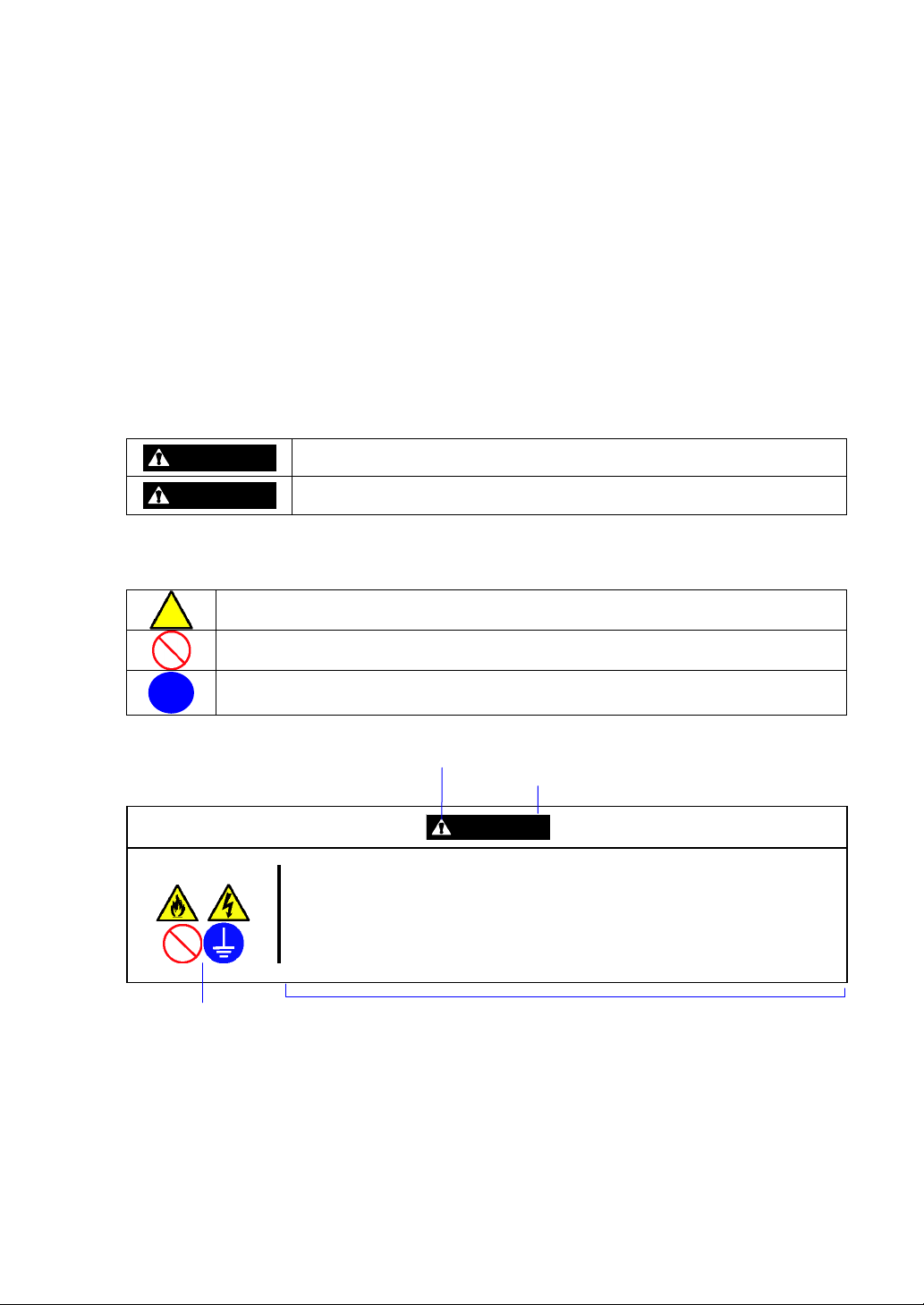
In this manual or warning labels, "WARNING" or "CAUTION" is used to indicate a degree of danger.
These terms are defined as follows:
WARNING
CAUTION
Precautions and notices against hazards are presented with one of the following three symbols. The
individual symbols are defined as follows:
This symbol indicates the presence of a hazard if the instruction is ignored.
An image in the symbol illustrates the hazard type. (Attention)
This symbol indicates prohibited actions. An image in the symbol illustrates a
particular prohibited action. (Prohibited Action)
This symbol indicates mandatory actions. An image in the symbol illustrates a
mandatory action to avoid a particular hazard. (Mandatory Action)
(Example)
Plug in to a proper power source.
Term indicating a degree of danger
Indicates the presence of a hazard that may result in death or serious
personal injury if the instruction is ignored.
Indicates the presence of a hazard that may cause minor personal injury,
including burns, or property damage if the instruction is ignored.
Symbol to draw attention
CAUTION
Use a proper wall outlet of the specified voltage. Use of an improper power
source may cause a fire or a power leak.
Symbol indicating a prohibited
action (may not always be
indicated)
Description of a danger
Page 4
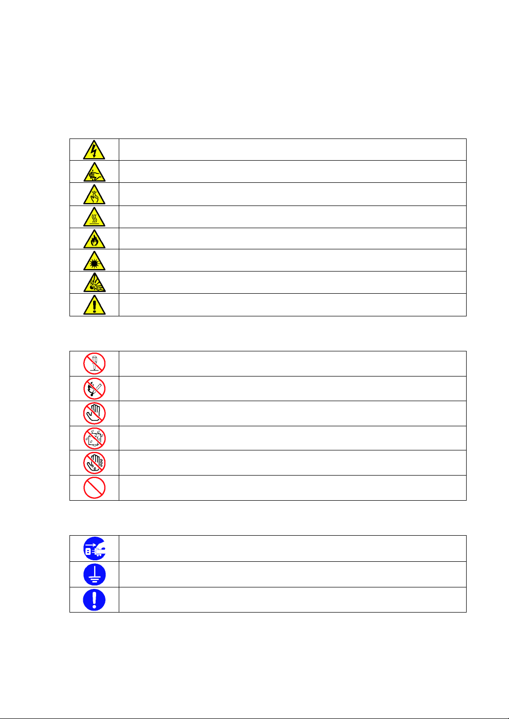
SYMBOLS USED IN THIS MANUAL AND WARNING LABELS
Attentions
Indicates that improper use may cause an electric shock.
Indicates that improper use may cause fingers to be caught.
Indicates that improper use may cause personal injury.
Indicates that improper use may cause personal injury.
Indicates that improper use may cause fumes or fire.
Indicates that improper use may cause loss of eyesight due to laser beam.
Indicates that improper use may cause explosion.
Indicates a general notice or warning that cannot be specifically identified.
Prohibited Actions
Do not disassemble, repair, or modify the server. Otherwise, an electric shock or fire
may be caused.
Do not place the server near the fire. Otherwise, a fire may be caused.
Do not touch the component specified by this symbol. Otherwise, an electric shock or
burn may be caused.
Do not use the server in the place where water or liquid may pour. Otherwise, an
electric shock or fire may be caused.
Do not touch the server with wet hand. Otherwise, an electric shock may be caused.
Indicates a general prohibited action that cannot be specifically identified.
Mandatory Action
Unplug the power cord of the server. Otherwise, an electric shock or fire may be
caused.
Be sure to provide earthing. Otherwise, an electric shock or fire may be caused.
Indicates a mandatory action that cannot be specifically identified. Make sure to follow
the instruction.
Page 5

NOTE: This equipment has been tested and found to comply with the limits for a Class A digital
device, pursuant to Part 15 of the FCC Rules. These limits are designed to provide reasonable
protection against harmful interference when the equipment is operated in a commercial
environment. This equipment generates, uses, and can radiate radio frequency energy and, if not
installed and used in accordance with the instruction manual, may cause harmful interference to
radio communications. Operation of this equipment in a residential area is likely to cause harmful
interference in which case the user will be required to correct the interference at his own expense.
CE Statement
Warning : This is a Class A product. In domestic environment this product may cause radio
interference in which case the user may be required to take adequate measures (EN55022).
BSMI Statement
Page 6

Trademarks
NEC ESMPRO and NEC EXPRESSBUILDER are trademarks of NEC Corporation.
Microsoft, Windows, Windows Server, and MS-DOS are registered trademarks or trademarks of Microsoft Corporation in the
United States and other countries.
Intel, Pentium, Xeon, and Celeron are registered trademarks of Intel Corporation.
PCI Express is a trademark of Peripheral Component Interconnect Special Interest Group.
Datalight is a registered trademark of Datalight, Inc.
ROM-DOS is a registered trademark of Datalight, Inc.
AT is a registered trademark of International Business Machines Corporation in the United States and other countries.
Adaptec and its logo is a registered trademark of Adaptec, Inc. of United States.
LSI, the LSI logo design, iBBU, MegaRAID, and WebBIOS are trademarks or registered trademarks of LSI Corporation of
United States.
Adobe, Adobe logo, and Acrobat are trademarks of Adobe Systems Incorporated.
Advanced Intelligent Tape is a trademark of the Sony Corporation.
Promise Technology, Inc. and Promise Technology, Inc. logo are trademarks of Promise Technology Incorporated.
AVOCENT and DVC (Dambrackas Video Compression) are registered trademarks or trademarks of AVOCENT in the United
States and other countries.
All other product, brand, or trade names used in this publication are the trademarks or registered trademarks of their
respective trademark owners.
Windows Server 2008 R2 stands for Microsoft® Windows Server® 2008 R2 Standard operating system and Microsoft®
Windows Server® 2008 R2 Enterprise operating system. Windows 7 stands for Microsoft® Windows® 7 Professional
operating system. Windows Server 2008 stands for Microsoft® Windows Server® 2008 Standard operating system and
Microsoft® Windows Server® 2008 Enterprise operating system. Windows Vista stands for Microsoft® Windows Vista®
Business operating system. Windows Server 2003 x64 Editions stands for Microsoft® Windows Server® 2003 R2, Standard
x64 Edition Operating system and Microsoft® Windows Server® 2003 R2, Enterprise x64 Edition operating system, or
Microsoft® Windows Server® 2003, Standard x64 Edition operating system and Microsoft® Windows Server® 2003,
Enterprise x64 Edition operating system. Windows Server 2003 stands for Microsoft® Windows Server® 2003 R2, Standard
Edition operating system and Microsoft® Windows Server® 2003 R2, Enterprise Edition operating system, or Microsoft®
Windows Server® 2003, Standard Edition operating system and Microsoft® Windows Server® 2003, Enterprise Edition
operating system. Windows XP x64 Edition stands for Microsoft® Windows® XP Professional x64 Edition operating system.
Windows XP stands for Microsoft® Windows® XP Home Edition operating system and Microsoft® Windows® XP
Professional operating system. Windows 2000 stands for Microsoft® Windows® 2000 Server operating system and
Microsoft® Windows® 2000 Advanced Server operating system, and Microsoft® Windows® 2000 Professional operating
system. Windows NT stands for Microsoft® Windows NT® Server network operating system version 3.51/4.0 and
Microsoft® Windows NT® Workstation operating system version 3.51/4.0. Windows Me stands for Microsoft® Windows®
Millennium Edition operating system. Windows 98 stands for Microsoft® Windows®98 operating system. Windows 95
stands for Microsoft® Windows®95 operating system. WinPE stands for Microsoft® Windows® Preinstallation
Environment.
Momentary voltage drop prevention:
This product may be affected by a momentary voltage drop caused by lightning. To prevent a momentary
voltage drop, an AC uninterruptible power supply (UPS) unit should be used.
Notes:
(1) No part of this manual may be reproduced in any form without the prior written permission of NEC
Corporation.
(2) The contents of this manual may be revised without prior notice.
(3) The contents of this manual shall not be copied or altered without the prior written permission of NEC
Corporation.
(4) All efforts have been made to ensure the accuracy of all information in this manual. If you notice any part
unclear, incorrect, or omitted in this manual, contact the sales agent where you purchased this product.
(5) NEC assumes no liability arising from the use of this product, nor any liability for incidental or
consequential damages arising from the use of this manual regardless of Item (4).
Page 7

PREFACE
Congratulations on the purchase of your NEC Express server.
Purchase of this server is your assurance of receiving state-of-the-art, high quality hardware to meet
your needs, both now and in the future.
Read this User's Guide thoroughly to fully understand handling of the NEC Express server and
appreciate its functions to the maximum extent.
i
Page 8

ii
ABOUT THIS USER'S GUIDE
This manual is a guide for proper setup and use of your server.
This manual also covers useful procedures for dealing with difficulties and problems that may arise
during setup or operation of your server.
Keep this manual for future use.
The following describes how to proceed with this manual.
How to Use This Manual
To aid you in finding information quickly, this manual contains the following information:
Chapter 1 Notes on Using Your Server
includes information that needs attention to use the server. Make sure to read this chapter
before setting up and using the server. It also includes requirements and advisory information
for transfer and disposal of the server.
Chapter 2 General Description
includes information necessary to use the server, such as names and functions of its
components, handling of the optical disk drive.
Chapter 3 Setting Up Your Server
tells you how to select a site, unpack the system, make cable connections, and power on your
system.
Chapter 4 Configuring Your Server
tells you how to configure the system and provides instructions for running the BIOS SETUP
Utility and the RAID configuration utility, which is used to configure RAID drives in your system.
This chapter also provides information on mother board jumper settings.
Chapter 5 Installing the Operating System with Express Setup
describes how to install the operating system.
Chapter 6 Installing and Using Utilities
describes how to install the utilities for the server. It also includes a description on using the
attached "NEC EXPRESSBUILDER" DVD.
Chapter 7 Maintenance
provides you with all the information necessary to maintain successful operation of the server.
This chapter also includes a description on relocating and storing the server.
Chapter 8 Troubleshooting
contains helpful information for solving problems that might occur with your system.
Chapter 9 Upgrading Your Server
provides you with instructions for upgrading your system with an additional processor, optional
memory, optional add-in cards, hard disk drives, peripheral devices, and power supply.
Chapter 10 Internal Cabling Diagram
includes cabling information for the SATA2 controller, 5.25-inch device, and the power supply.
Appendix A Specification
provides specifications for your server.
Appendix B Other Precautions
provides supplementary notes on using the server.
Appendix C IRQ
provides a list of factory-set IRQs.
Page 9

Appendix D Installing Windows Server 2008 R2
describes how to install Microsoft Windows Server 2008 R2 without using Express Setup. Using
the Express Setup tool is recommended for installing Windows Server 2008 R2. See Chapter 5
for details.
Appendix E Installing Windows Server 2008
describes how to install Microsoft Windows Server 2008 without using Express Setup. Using the
Express Setup tool is recommended for installing Windows Server 2008. See Chapter 5 for
details.
Appendix F Installing Windows Server 2003 x64 Editions
describes how to install Microsoft Windows Server 2003 x64 Editions without using Express
Setup. Using the Express Setup tool is recommended for installing Windows Server 2003 x64
Editions. See Chapter 5 for details.
Appendix G Installing Windows Server 2003
describes how to install Microsoft Windows Server 2003 without using Express Setup. Using the
Express Setup tool is recommended for installing Windows Server 2003. See Chapter 5 for
details.
Appendix H Using a Client Computer Which Has a CD Drive
describes how to install the management software of EXPRESSBUILDER to the client computer
without the DVD drive.
Appendix I Product Configuration Record Table
provides a table to be filled with your server configuration.
iii
Text Conventions
The following conventions are used throughout this manual. For safety symbols, see "SAFETY
INDICATIONS" provided earlier.
IMPORTANT:
NOTE:
Items that are mandatory or require attention when using the server
Helpful and convenient piece of information
IN THE PACKAGE
The carton contains various accessories, as well as the server itself. See the “Getting Started” to
make sure that you have everything and that individual components are not damaged. If you find
any component missing or damaged, contact your service representative.
Store the provided accessories in a designated place for your convenience. You will need
them to install an optional device or troubleshoot your server, as well as to set it up.
Make a backup copy of each provided floppy disk, if any. Store the original disk as the
master disk in a designated place, and use its copy.
Improper use of any provided floppy disk or CD-ROM may alter your system
environment. If you find anything unclear, immediately ask your service representative for
help.
Page 10

iv
CONTENTS
Preface ..............................................................................................................................................
About This User's Guide..................................................................................................................ii
In the Package.................................................................................................................................iii
Chapter 1 Notes on Using Your Server........................................................................ 1-1
Warning Labels.............................................................................................................................1-2
Safety Notes..................................................................................................................................1-3
General .....................................................................................................................................1-3
Power Supply and Power Cord Use .........................................................................................1-4
Installation, Relocation, Storage, and Connection....................................................................1-6
Cleaning and Working with Internal Devices...........................................................................1-7
During Operation .....................................................................................................................1-8
For Proper Operation....................................................................................................................1-9
Transfer to Third Party................................................................................................................1-10
Disposal and Consumables.........................................................................................................1-11
Regarding the Transportation of this System.............................................................................. 1-11
User Support...............................................................................................................................1-11
USE of the term “Optical Disk drive” ........................................................................................1-11
USE of the term “hard disk drive”..............................................................................................1-12
i
Chapter 2 General Description ..................................................................................... 2-1
Overview ......................................................................................................................................2-2
System Chassis .............................................................................................................................2-3
Front View................................................................................................................................2-3
Rear View.................................................................................................................................2-5
Internal View............................................................................................................................2-7
Mother Board .........................................................................................................................2-10
Standard Features........................................................................................................................2-11
Remote Power-On Feature (Wake On LAN)..........................................................................2-12
AC LINK Feature...................................................................................................................2-12
Security ..................................................................................................................................2-12
Running the Server with the Fan Set to Low-speed Mode (Silent Mode)..............................2-13
NEC EXPRESSBUILDER.....................................................................................................2-13
NEC ESMPRO.......................................................................................................................2-14
Maintenance Tools .................................................................................................................2-14
System Diagnostic Utility ......................................................................................................2-14
Using Your Server.......................................................................................................................2-15
POWER/SLEEP Switch.........................................................................................................2-15
Power Off...............................................................................................................................2-19
SLEEP Switch........................................................................................................................2-19
Optical Disk Drive .................................................................................................................2-20
Flash FDD ..............................................................................................................................2-23
Chapter 3 Setting Up Your Server ................................................................................ 3-1
Setup Flow....................................................................................................................................3-2
UNPACKING THE SYSTEM......................................................................................................3-3
Installing Optional Devices ..........................................................................................................3-3
Page 11

v
Selecting Server Site.....................................................................................................................3-4
Connecting Peripheral Devices.....................................................................................................3-6
Connecting Power Cord................................................................................................................3-8
Turning On the Server ................................................................................................................3-10
Installing Operating System .......................................................................................................3-12
Installing Utilities .......................................................................................................................3-12
Making Backup Copies of System Information..........................................................................3-12
Chapter 4 Configuring Your Server.............................................................................. 4-1
System BIOS (BIOS Setup Utility) ..............................................................................................4-2
Starting SETUP Utility.............................................................................................................4-3
Description on On-Screen Items and Key Usage.....................................................................4-4
Configuration Examples...........................................................................................................4-5
Menu and Parameter Descriptions ...........................................................................................4-9
RAID System Configuration ......................................................................................................4-23
RAID......................................................................................................................................4-23
Configuration by Onboard RAID Controller..........................................................................4-28
Setup Utility ...........................................................................................................................4-30
LSI Software RAID Configuration Utility and Universal RAID Utility................................4-43
Configuring Mother Board Jumpers...........................................................................................4-46
Chapter 5 Installing the Operating System with Express Setup............................... 5-1
About Express Setup ....................................................................................................................5-2
Windows Server 2008 R2.............................................................................................................5-3
Notes on Windows Installation.................................................................................................5-3
Flow of Setup ...........................................................................................................................5-8
Installing the Windows Server 2008 R2...................................................................................5-9
Installing and Setting Device Drivers.....................................................................................5-22
Setting for Solving Problems .................................................................................................5-27
BitLocker................................................................................................................................5-27
Windows Server 2008.................................................................................................................5-28
Notes on Windows Installation...............................................................................................5-28
Flow of Setup .........................................................................................................................5-33
Installing the Windows Server 2008.......................................................................................5-34
Installing and Setting Device Drivers.....................................................................................5-48
Setting for Solving Problems .................................................................................................5-54
Windows Server 2003.................................................................................................................5-55
Notes on Windows Installation...............................................................................................5-55
Flow of Setup..............................................................................................................................5-60
Installing Windows Server 2003.................................................................................................5-61
Installing and Setting Device Drivers.........................................................................................5-71
PROSet...................................................................................................................................5-71
Network Driver ......................................................................................................................5-73
Optional Network Board Driver.............................................................................................5-74
Setup Team.............................................................................................................................5-75
Setting WOL ..........................................................................................................................5-77
Graphics Accelerator Driver...................................................................................................5-79
Installing SCSI Controller Driver (N8103-75/95/107)...........................................................5-79
Installing SAS Controller Driver (N8103-104A) ...................................................................5-79
Setting for Solving Problems .................................................................................................5-79
Page 12

vi
Setting for Solving Problems......................................................................................................5-80
Memory Dump (Debug Information).....................................................................................5-80
How to Create a User-mode Process Dump File....................................................................5-87
Network Monitor....................................................................................................................5-90
Re-installing the Operation System if Multiple Logical Drives Exist....................................5-92
Installing Maintenance Utilities..................................................................................................5-94
Updating the System...................................................................................................................5-94
Making Backup Copies of System Information..........................................................................5-95
Installing with the OEM-Disk for Mass Storage Device........................................................5-96
Chapter 6 Installing and Using Utilities ....................................................................... 6-1
NEC EXPRESSBUILDER...........................................................................................................6-2
Autorun Menu ..........................................................................................................................6-6
Parameter File Creator..................................................................................................................6-7
Parameter File ..........................................................................................................................6-8
NEC ESMPRO ...........................................................................................................................6-21
Functions and Features...........................................................................................................6-21
NEC ExpressUpdate Agent.........................................................................................................6-22
Universal RAID Utility...............................................................................................................6-23
Setup with Express Setup.......................................................................................................6-23
Manual Setup .........................................................................................................................6-23
Management of RAID System using NEC ESMPRO Manager.............................................6-24
Easy Configuration.................................................................................................................6-24
Creating Logical Drive of RAID 6.........................................................................................6-24
NEC Product Info Collection Utility ..........................................................................................6-25
Installation..............................................................................................................................6-25
Using Utility...........................................................................................................................6-26
Uninstallation .........................................................................................................................6-26
Chapter 7 Maintenance.................................................................................................. 7-1
Making Backup Copies.................................................................................................................7-1
Cleaning........................................................................................................................................7-2
Cleaning the Server ..................................................................................................................7-3
Cleaning the Keyboard/Mouse.................................................................................................7-3
Cleaning Disc ...........................................................................................................................7-4
System Diagnostics.......................................................................................................................7-5
Test Items.................................................................................................................................7-5
Startup and Exit of System Diagnostics ...................................................................................7-6
Relocating/Storing The Server......................................................................................................7-9
Chapter 8 Troubleshooting ........................................................................................... 8-1
System Viewers ............................................................................................................................8-2
Lamps ...........................................................................................................................................8-3
POWER/SLEEP Lamp.............................................................................................................8-4
DISK ACCESS Lamp ..............................................................................................................8-4
Access Lamp ............................................................................................................................8-4
LINK/ACT Lamp.....................................................................................................................8-4
1000/100/10 Lamp ...................................................................................................................8-4
Error Messages .............................................................................................................................8-5
Error Messages after Power-on................................................................................................8-5
Page 13

vii
POST Error Messages ..............................................................................................................8-6
Beep Codes...............................................................................................................................8-8
DMI Event Log ........................................................................................................................8-9
Solving Problems........................................................................................................................8-11
Problems with NEC Express Server.......................................................................................8-11
Problems with Windows.........................................................................................................8-17
Problems with NEC EXPRESSBUILDER ............................................................................8-27
Problems with Express Setup.................................................................................................8-28
Problems with Parameter File Creator ...................................................................................8-29
Problems with RAID System Configuration..........................................................................8-30
Problems with Windows Autorun Menu ................................................................................8-32
Others .....................................................................................................................................8-33
Collecting Event Log .............................................................................................................8-34
Collect Configuration Information.........................................................................................8-34
Collecting Dr. Watson Diagnostic Information ......................................................................8-35
Memory Dump.......................................................................................................................8-35
Recovery for Windows System...................................................................................................8-36
Maintenance Tools......................................................................................................................8-37
Starting Maintenance Tools....................................................................................................8-37
Function of Maintenance Tools ..............................................................................................8-40
Resetting the Server....................................................................................................................8-42
Forced Shutdown........................................................................................................................8-43
Chapter 9 Upgrading Your Server ................................................................................ 9-1
Safety Notes..................................................................................................................................9-2
Static Precautions..........................................................................................................................9-3
Preparing for Installation and Removal........................................................................................9-4
Installation or Removal Procedure ...............................................................................................9-5
Side Cover................................................................................................................................9-5
Front Bezel...............................................................................................................................9-9
3.5-inch Hard Disk Drive.......................................................................................................9-11
2.5-inch Hard Disk Drive Cage (Option) ...............................................................................9-18
Use of Internal Hard Disk Drives in the RAID System..........................................................9-23
Additional Battery for Optional RAID Controller .................................................................9-28
PCI Board...............................................................................................................................9-36
Installation of N8117-01A RS-232C Connector Kit...............................................................9-43
DIMM ....................................................................................................................................9-45
File Device .............................................................................................................................9-50
Optical Disk Drive .................................................................................................................9-56
Chapter 10 Internal Cabling Diagrams....................................................................... 10-1
Interface Cables ..........................................................................................................................10-2
Addition of Hard Disk Drive..................................................................................................10-2
Connection of 5.25-inch Device.............................................................................................10-6
Power Cables ..............................................................................................................................10-9
Onboard SATA HDD..............................................................................................................10-9
With Optional RAID Controller Installed ............................................................................10-10
Appendix A Specifications............................................................................................ A-1
Page 14

viii
Appendix B Other Precautions.....................................................................................B-1
Transfer Rate of the On-board LAN Controller ...................................................................... B-1
Server Management Software .................................................................................................B-1
Floppy Disk............................................................................................................................. B-1
DVD/CD-ROM....................................................................................................................... B-4
Tape Media.............................................................................................................................. B-4
Keyboard................................................................................................................................. B-5
Mouse...................................................................................................................................... B-6
Appendix C IRQ..............................................................................................................C-1
Appendix D Installing Windows Server 2008 R2 ........................................................D-1
Notice ..........................................................................................................................................D-1
Optional Board Supported by NEC EXPRESSBUILDER...................................................... D-1
Service Pack Which EXPRESSBUILDER Supports .............................................................. D-2
Installing Service Pack............................................................................................................D-2
Updating System .....................................................................................................................D-2
Installing on the Mirrored Volume ..........................................................................................D-2
Mounting MO Device .............................................................................................................D-2
About Removable Media ........................................................................................................D-2
Floppy Disk Drive...................................................................................................................D-2
About the System Partition Size..............................................................................................D-3
BitLocker.................................................................................................................................D-4
Installing Windows Server 2008 R2 ............................................................................................ D-6
Preparations for Installation ....................................................................................................D-6
Creating "Windows Server 2008 R2 OEM-Disk for EXPRESSBUILDER" ..........................D-6
Windows Server 2008 R2 Clean Installation...........................................................................D-9
Procedure for License Authentication ...................................................................................D-18
Updating the System .............................................................................................................D-18
Driver Installation and Advanced Settings ................................................................................D-21
LAN Driver and PROSet.......................................................................................................D-21
Network Driver .....................................................................................................................D-22
Optional Network Board Driver (N8104-121/125A/126).....................................................D-22
Setup Team............................................................................................................................D-23
Setting WOL .........................................................................................................................D-26
Graphics Accelerator Driver..................................................................................................D-27
Installing SCSI Controller Driver (N8103-75/107)............................................................... D-27
Installing SAS Controller Driver (N8103-104A) ..................................................................D-27
About Windows Activation ...................................................................................................D-28
Setting for Solving Problems.....................................................................................................D-32
Appendix E Installing Windows Server 2008 .............................................................. E-1
Notice .......................................................................................................................................... E-1
Optional Board Supported by NEC EXPRESSBUILDER...................................................... E-1
Service Pack Which EXPRESSBUILDER Supports .............................................................. E-2
Installing Service Pack............................................................................................................ E-2
Updating System ..................................................................................................................... E-2
Installing on the Mirrored Volume .......................................................................................... E-2
Mounting MO Device ............................................................................................................. E-2
Page 15

ix
About Removable Media ........................................................................................................ E-2
Floppy Disk Drive................................................................................................................... E-2
About the System Partition Size.............................................................................................. E-3
BitLocker................................................................................................................................. E-5
Installing Windows Server 2008..................................................................................................E-6
Preparations for Installation .................................................................................................... E-6
Creating "Windows Server 2008 OEM-Disk for EXPRESSBUILDER"................................ E-6
Windows Server 2008 Clean Installation ................................................................................ E-9
Procedure for License Authentication ................................................................................... E-20
Updating the System .............................................................................................................E-20
Driver Installation and Advanced Settings ................................................................................ E-23
LAN Driver and PROSet....................................................................................................... E-23
Network Driver ..................................................................................................................... E-25
Optional Network Board Driver (N8104-112/119/120/121/125A/126) ................................ E-25
Setup Team............................................................................................................................ E-26
Setting WOL ......................................................................................................................... E-28
Graphics Accelerator Driver.................................................................................................. E-29
Installing SCSI Controller Driver (N8103-75/95/107).......................................................... E-29
Installing SAS Controller Driver (N8103-104A) .................................................................. E-29
About Windows Activation ................................................................................................... E-30
Setting for Solving Problems..................................................................................................... E-34
Appendix F Installing Windows Server 2003 x64 Editions ........................................ F-1
Notice .......................................................................................................................................... F-1
Optional Board Supported by NEC EXPRESSBUILDER...................................................... F-1
Service Pack Which EXPRESSBUILDER Supports .............................................................. F-2
Installing Service Pack............................................................................................................ F-2
Updating System ..................................................................................................................... F-2
Re-installing to the Hard Disk Drive which has been upgraded to Dynamic Disk ................. F-2
Mounting MO Device ............................................................................................................. F-2
About Removable Media ........................................................................................................ F-2
Floppy Disk Drive................................................................................................................... F-2
About the System Partition Size.............................................................................................. F-3
Installing Windows Server 2003 x64 Editions............................................................................. F-4
Creating "Windows Server 2003 x64 Edition OEM-Disk for EXPRESSBUILDER" ......... F-4
Windows Server 2003 x64 Editions Clean Installation ........................................................... F-7
Procedure for License Authentication ....................................................................................F-11
Updating the System - Applying Service Pack - ................................................................... F-12
Driver Installation and Advanced Settings ................................................................................ F-19
PROSet.................................................................................................................................. F-19
Network Driver ..................................................................................................................... F-21
Optional Network Board Driver............................................................................................ F-22
Setup Team............................................................................................................................ F-23
Setting WOL ......................................................................................................................... F-25
Graphics Accelerator Driver.................................................................................................. F-27
Installing SCSI Controller Driver (N8103-75/107)............................................................... F-27
Installing SCSI Controller Driver (N8103-95)...................................................................... F-27
Installing SAS Controller Driver (N8103-104A) .................................................................. F-27
About Windows Activation ................................................................................................... F-28
Setting for Solving Problems..................................................................................................... F-29
Page 16

x
Appendix G Installing Windows Server 2003..............................................................G-1
BEFORE INSTALLING WINDOWS SERVER 2003 ................................................................G-1
Optional Board Supported by NEC EXPRESSBUILDER...................................................... G-1
Service Pack Which EXPRESSBUILDER Supports .............................................................. G-2
Application of Service Pack....................................................................................................G-2
Updating System .....................................................................................................................G-2
Re-installing to the Hard Disk which has been upgraded to Dynamic Disk ...........................G-2
Mounting MO Device .............................................................................................................G-2
About Removable Media ........................................................................................................G-2
Floppy Disk Drive...................................................................................................................G-2
About the System Partition Size..............................................................................................G-3
Installing Windows Server 2003..................................................................................................G-5
Creating "Windows Server 2003 OEM-Disk for EXPRESSBUILDER"................................G-5
Windows Server 2003 Clean Installation ................................................................................ G-7
Procedure for License Authentication ...................................................................................G-12
Updating the System - Applying Service Pack - ...................................................................G-12
Driver Installation and Advanced Settings ................................................................................G-18
PROSet..................................................................................................................................G-18
Network Driver .....................................................................................................................G-19
Optional Network Board Driver............................................................................................ G-19
Setup Team............................................................................................................................G-20
Setting WOL .........................................................................................................................G-20
Graphics Accelerator Driver..................................................................................................G-22
Installing SCSI Controller Driver (N8103-75/95/107).......................................................... G-22
Installing SAS Controller Driver (N8103-104A) ..................................................................G-22
About Windows Activation ...................................................................................................G-23
Setting for Solving Problems.....................................................................................................G-24
Appendix H Using a Client Computer Which Has a CD Drive...................................H-1
Appendix I Product Configuration Record Table......................................................... I-1
Hardware.................................................................................................................................. I-1
Software ................................................................................................................................... I-3
Page 17

Chapter 1
Notes on Using Your Server
This chapter includes information necessary for proper and safe operation of your server.
Page 18
1-2 Notes on Using Your Server
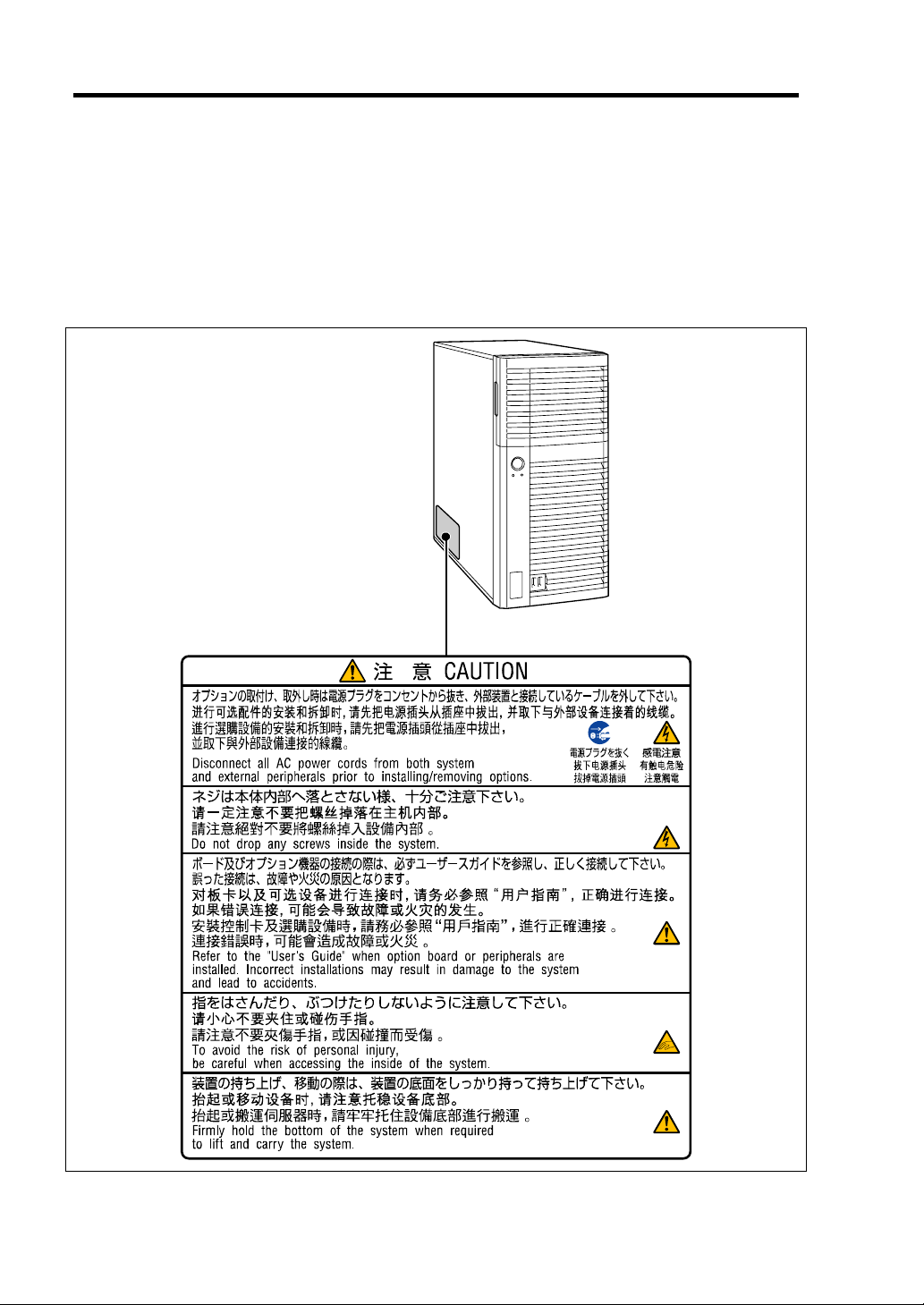
WARNING LABELS
The warning label is attached to components with possible danger or their vicinity in your server to
inform the user that a hazardous situation may arise when operating the server. (Do not intentionally
remove or damage any of the labels.)
If you find any labels totally/partially removed or illegible due to damage, contact your sales
representative.
Page 19
Notes on Using Your Server 1-3
SAFETY NOTES
This section provides notes on using your server safely. Read this section carefully to ensure proper
and safe use of the server. For symbols, see "SAFETY INDICATIONS" provided earlier.
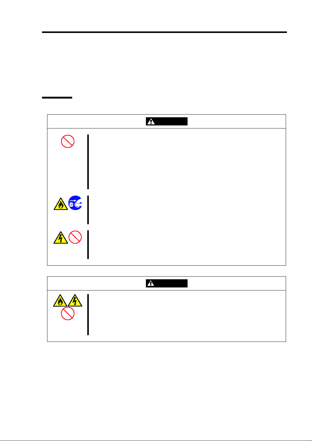
General
WARNING
Do not use the server for services where critical high availability may directly
affect human lives.
Your server is not intended to be used with or control facilities or devices
concerning human lives, including medical devices, nuclear facilities and
devices, aeronautics and space devices, transportation facilities and devices;
and facilities and devices requiring high reliability. NEC assumes no liability for
any accident resulting in personal injury, death, or property damage if the
server has been used in the above conditions.
Do not use the server if any smoke, odor, or noise is present.
If smoke, odor, or noise is present, immediately turn off the server and
disconnect the power plug from the outlet, then contact your service
representative. Using the server in such conditions may cause a fire.
Keep needles or metal objects away from the server.
Do not insert needles or metal objects into ventilation holes in the server or
openings in the floppy disk or optical disk drive. Doing so may cause an electric
shock.
Keep water or foreign matter away from the server.
Do not let any form of liquid (water etc.) or foreign matter (e.g., pins or paper
clips) enter the server. Failure to follow this warning may cause an electric
shock, a fire, or a failure of the server. When such things accidentally enter the
server, immediately turn off the power and disconnect the power plug from the
outlet. Do not disassemble the server. Contact your service representative.
CAUTION
Page 20
1-4 Notes on Using Your Server
Power Supply and Power Cord Use
Do not hold the power plug with a wet hand.
Do not disconnect/connect the plug while your hands are wet. Failure to follow
this warning may cause an electric shock.
Do not connect the ground wire to a gas pipe.
Never connect the ground wire to a gas pipe. Failure to follow this warning may
cause a gas explosion.
Plug in to a proper power source.
Use a proper wall outlet of the specified voltage. Use of an improper power
source may cause a fire or a power leak.
Do not install the server where you need an extension cord. Use of a cord that
does not meet the power specifications of your server may heat up the cord and
cause a fire.
Do not connect the power cord to an outlet that has an illegal number of
connections.
The electric current exceeding the rated flow overheats the outlet, which may
cause a fire.
Do not pull the cable when disconnecting it.
When disconnecting the cable from the device, hold the cable connector and
pull it straight out. Pulling the cable out by the cable portion or giving
mechanical stress to the connector could damage the cables and connectors to
result in an electrical shock hazard or a fire.
Insert the power plug into the outlet as far as it goes.
Heat generation resulting from a halfway inserted power plug (imperfect
contact) may cause a fire. Heat will also be generated if condensation is formed
on dusty blades of the halfway inserted plug, increasing the possibility of fire.
WARNING
CAUTION
Page 21
Notes on Using Your Server 1-5
Use the authorized power cord only.
Use only the power cord that comes with your server. Use of an unauthorized
power cord may cause a fire when the electric current exceeds the rated flow.
Also, observe the following to prevent an electric shock or fire caused by a
damaged cord.
Do not stretch the cord harness.
Do not pinch the power cord.
Do not bend the power cord.
Keep chemicals away from the power cord.
Do not twist the power cord.
Do not place any object on the power cord.
Do not bundle power cords.
Do not alter, modify, or repair the power cord.
Do not secure the power cord with staples or equivalents.
Do not use any damaged power cord. (Replace a damaged power cord with
a new one of the same specifications. Ask your service representative for
replacement.)
Do not use the attached power cord for any other devices or usage.
The power cord that comes with your server is designed aiming to connect with
this server and to use with the server, and its safety has been tested. Do not
use the attached power cord for any other purpose. Doing so may cause a fire
or an electric shock.
CAUTION
Page 22
1-6 Notes on Using Your Server
Installation, Relocation, Storage, and Connection
CAUTION
Do not hold the front bezel to lift the server.
Do not hold the front bezel to lift the server. The front bezel may be disengaged
from the server, causing personal injury. Hold the server firmly by its bottom.
Do not install the server in any place other than specified.
Do not install the server in the following places or any place other than specified
in this manual. Failure to follow this instruction may cause a fire.
a dusty place
a humid place such as near a boiler
a place exposed to direct sunlight
an unstable place
Do not use the server in the place where corrosive gases exist.
Make sure not to locate or use the server in the place where corrosive gases
(sulfur dioxide, hydrogen sulfide, nitrogen dioxide, chlorine, ammonia, ozone,
etc.) exist.
Also, do not set it in the environment where the air (or dust) includes
components accelerating corrosion (ex. sulfur, sodium chloride) or conductive
metals. There is a risk of a fire due to corrosion and shorts of an internal printed
board.
Do not connect any interface cable with the power cord of the server plugged to
a power source.
Make sure to power off the server and unplug the power cord from a power
outlet before installing/removing any optional internal device or
connecting/disconnecting any interface cable to/from the server. If the server is
off-powered but its power cord is plugged to a power source, touching an
internal device, cable, or connector may cause an electric shock or a fire
resulted from a short circuit.
Do not use any unauthorized interface cable.
Use only interface cables provided by NEC and locate a proper device and
connector before connecting a cable. Using an authorized cable or connecting
a cable to an improper destination may cause a short circuit, resulting in a fire.
Also, observe the following notes on using and connecting an interface cable.
Do not use any damaged cable connector.
Do not step on the cable.
Do not place any object on the cable.
Do not use the server with loose cable connections.
Page 23
Cleaning and Working with Internal Devices
Notes on Using Your Server 1-7
Do not disassemble, repair, or alter the server.
Never attempt to disassemble, repair, or alter the server on any occasion other
than described in this manual. Failure to follow this instruction may cause an
electric shock or fire as well as malfunctions of the server.
Do not look into the optical disk drive.
A laser beam used in the optical disk drive is harmful to the eyes. Do not look
into or insert a mirror into the drive while the drive is powered. If a laser beam is
caught in your eyes, you may lose your eyesight (the laser beam is invisible).
Do not remove the lithium battery.
Your server contains the lithium battery. Do not remove the battery. Placing the
lithium close to a fire or in the water may cause an explosion.
When the server does not operate appropriately due to the dead lithium battery,
contact your service representative. Do not disassemble the server to replace
or recharge the battery by yourself.
Disconnect the power plug before accessing inside the server, or connecting
the peripherals.
Make sure to power off the server and disconnect the power plug from a power
outlet before cleaning or installing/removing internal optional devices. Touching
any internal device of the server with its power cord connected to a power
source may cause an electric shock even of the server is off-powered.
Disconnect the power plug from the outlet occasionally and clean the plug with
a dry cloth. Heat will be generated if condensation is formed on a dusty plug,
which may cause a fire.
Avoid installation in extreme temperature conditions.
Immediately after the server is powered off, its internal components such as
hard disk drives are very hot. Leave the server until its internal components fully
cool down before installing/removing any component.
Make sure to complete board installation.
Always install a board firmly. An incompletely installed board may cause a
contact failure, resulting in smoking or fire.
Protect the unused connectors with the protective cap.
The unused power supply cable connectors are covered with the protective cap
to prevent short circuits and electrical hazards, when removing the power
supply cable connector from the install devices, attach the protective cap to the
connector. Failure to follow this warning may cause a fire or an electric shock.
WARNING
CAUTION
Page 24
1-8 Notes on Using Your Server
During Operation
Stay away from the fan.
Keep your hand or hair away from the cooling fan on the rear of the server.
Failure to follow this warning may get your hand or hair caught in the fan,
resulting in injury.
Avoid contact with the server during thunderstorms.
Disconnect the power plug from the outlet when a thunderstorm is approaching.
If it starts thundering before you disconnect the power plug, do not touch any
part of the server including the cables. Failure to follow this warning may cause
a fire or an electric shock.
Keep animals away from the server.
Failure to follow this warning may cause a fire or an electric shock.
Do not leave the CD tray open.
If dust gets on the lens of optical disk drive, the drive may have problems
reading your disks.
Also, the CD tray may be broken by contacting any objects.
Do not place any object on top of the server.
The server may fall and cause property damage to the surroundings.
CAUTION
Page 25

Notes on Using Your Server 1-9
FOR PROPER OPERATION
Observe the following notes for successful operation of the server. Use of the server ignoring the
notes will cause malfunctions or failures of the server.
Install the server in a place that meets requirements for successful operation. For details,
see Chapter 3, "Setting Up Your Server."
If the power cord supplied with your system is not compatible with the AC wall outlet in
your region, contact your service representative to obtain a suitable power cord.
Make sure to power off the server before connecting or disconnecting cables between the
server and peripheral devices.
Verify that the access lamp on the server is unlit before turning off the server or ejecting
the floppy disk.
When plugging the power cord to the system, you may experience 10 seconds delay from
the time you press the POWER/SLEEP switch on the front panel. This is normal system
operation.
When you have just turned off the server, wait at least 10 seconds before turning it back
on. If the server is connected to the UPS, set at least 10 seconds delay in the power-on
schedule.
For the disk which does not conform to the CD standard, the playback of such a disk with
the CD drive is not guaranteed.
Turn off the power and unplug the power cord from the outlet before relocating the server.
Clean the server on a regular basis. (See Chapter 7 for cleaning.) Regular cleaning
proactively prevents various failures of the server.
Lightning may cause a momentary voltage drop. To prevent this problem, it is
recommended to use of an uninterruptible power supply unit.
Make sure to use optional devices supported by the server. Some non-supported devices
may be physically installed/connected but cause failures of the server as well as
malfunctions of the server.
NEC recommends you use NEC's genuine products. Some third-party products claim that
they support the server. However, repair of the server due to a failure or damage resulted
from use of such third-party products will be charged.
Turn off the cellular phone or pager. Radio interference may cause malfunctions of the
server.
Page 26

1-10 Notes on Using Your Server
TRANSFER TO THIRD PARTY
The following must be observed when you transfer (or sell) the server or software provided with the
server to a third party:
Make sure to provide this manual along with the server to a third party.
IMPORTANT: About data on the hard disk drive
Be sure to take appropriate measures not to leak important data (e.g.,
customers' information or companies' management information) on the
removed hard disk drive to any third parties.
Data seems to be erased when you empty "Recycle Bin" of Windows or
execute the "format" command of the operating system. However, the
actual data remains written on the hard disk drive. Data not erased
completely may be restored by special software and used for
unexpected purposes.
It is strongly recommended that the software or service (both available
at stores) for data erasure should be used in order to avoid the trouble
explained above. For details on data erasure, ask your sales
representative.
Provided software
To transfer or sell any software application that comes with the server to a third party, the following
requirements must be satisfied:
All provided software applications must be transferred and no backup copies must be
retained.
Transfer requirements listed in "Software License Agreement" that comes with each
software application must be satisfied.
Software applications that are not approved for transfer must be uninstalled before
transferring the server.
Page 27

Notes on Using Your Server 1-11
DISPOSAL AND CONSUMABLES
Dispose of the server, all the internal devices, floppy disks, CD-ROMs, and batteries
according to all national laws and regulations.
IMPORTANT: It is the user's responsibility to completely erase or
modify all the data stored in storage device such as hard disk drive so
that the data cannot be restored.
Your server contains some components that are only good for a limited period of time and
require replacement, such as fans, internal batteries, the internal optical disk drive, the
floppy disk drive, and the mouse. For stable operation of the server, NEC recommends
you replace these components on a regular basis. Consult with your service representative
for replacement or the product lives.
REGARDING THE TRANSPORTATION OF THIS SYSTEM
This system and/or associated options and accessories may be using lithium metal batteries or
lithium ion batteries.
There may be restrictions regarding the air or sea transportation of such lithium batteries.
Please contact your service representative prior to transporting this system and/or its options.
USER SUPPORT
Before Asking for Repair, do the following when the server appears to fail:
1. Check if the power cord and the cables to other devices are properly connected.
2. See Chapter 8 to find if your problem fits the description. If it does, take the
recommended measure for it.
3. Check if the software required for operation of the server is properly installed.
If the server still appears to fail after you have taken the above actions, consult with your service
representative immediately. Take notes on lamp indications of the server and alarm indications on
the display unit before consultation, which may provide a significant help to your service
representative.
USE OF THE TERM “OPTICAL DISK DRIVE”
This equipment includes one of the drives below. In this document, this drive is referred to as the
"optical disk drive".
DVD-ROM drive
DVD super multi drive
Page 28

1-12 Notes on Using Your Server
Note that the operation is not guaranteed when attempting use a CD playback device to play back a
disc that does not comply with the CD standards, such as a copy-protected CD.
USE OF THE TERM “HARD DISK DRIVE”
Unless otherwise specified, the term hard disk drive (HDD) when used in this document refers to
the following:
Hard disk drive (HDD)
Solid state drive (SSD)
Page 29
Advice for Health
Notes on Using Your Server 1-13
The longer you keep using the computer equipment, the more you
become tired, which may cause disorders of your body. When you use a
computer, observe the following to keep yourself from getting tired:
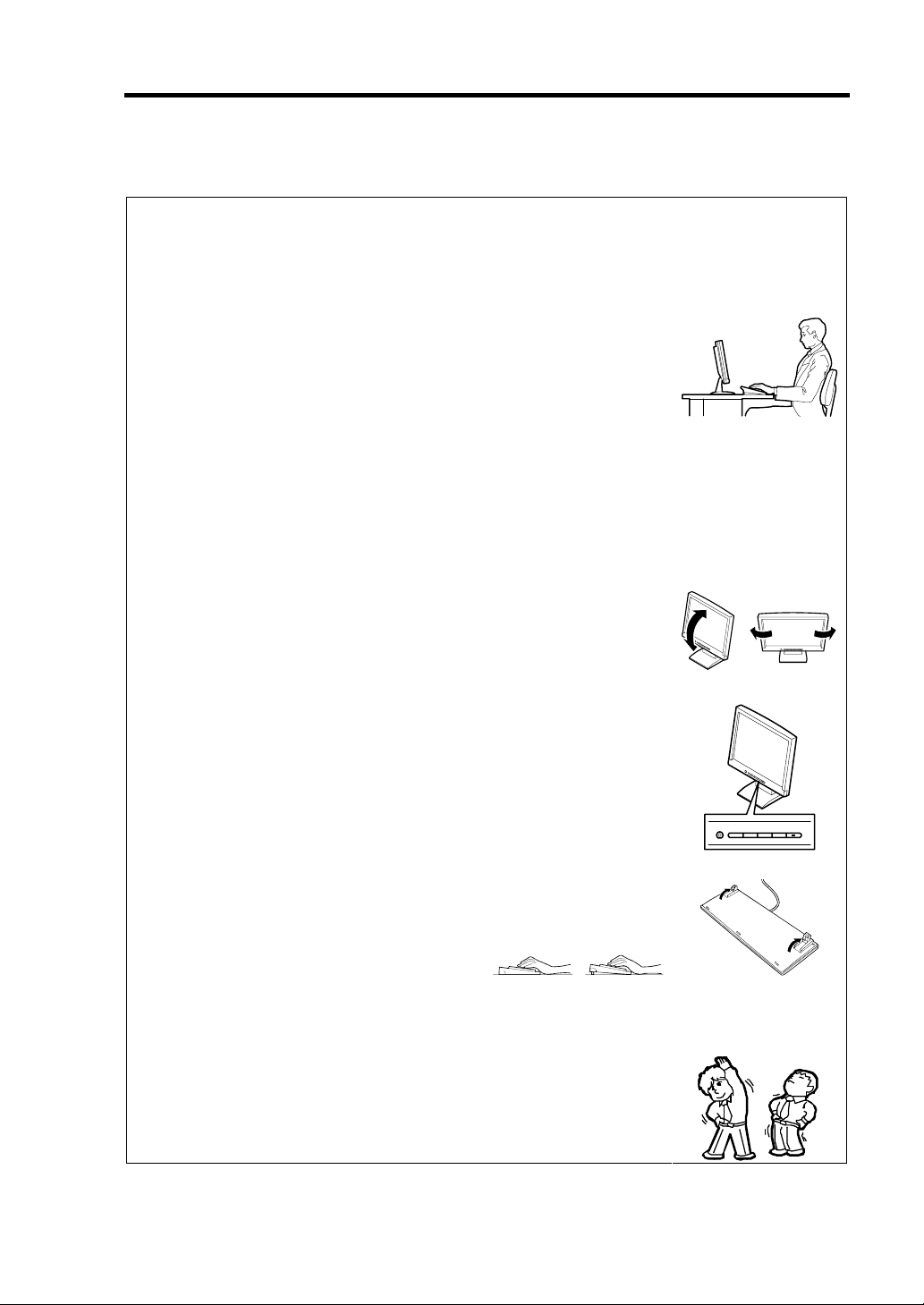
Good Working Posture
You have good posture if the following are satisfied when you use a
computer:
• You sit on a chair with your back straight.
• Your hands are parallel with the floor when you put them on the
keyboard.
• You look at the screen slightly lower than your eye height.
You have "good working posture" as described in the above when no part
of your body is under excess strain, in other words when your muscles
are most relaxed.
You have "bad posture" when you sit with your back hunched up or you
operate a display unit with your face close to the screen. Bad working
posture may cause eye strain or poor eyesight.
Adjustment of Display Unit Angles
Most display units are designed for adjustment of the horizontal and
vertical angles. This adjustment is important to prevent the screen from
reflecting bright lights and to make the display contents easy to see. You
will not be able to keep "good working posture" and you will feel more
tired than you should if you operate a display unit without adjusting
horizontal and vertical angles.
Adjustment of Screen Brightness and Contrast
The display unit has brightness and contrast adjustment functions. The
most suitable brightness and contrast depend on the individual and the
working environment (well-lighted room or insufficient light). Adjust
brightness and contrast so that the screen will be easy to see. An
extremely bright or dark screen will give a bad effect to your eyes.
Adjustment of Keyboard Angle
The keyboard provided with the server is designed for adjustment of an
angle. Adjust the keyboard angle at which the keyboard is easy to
operate. The adjustment assists in reducing strain on your shoulders,
arms, and fingers.
Cleaning of Equipment
Clean equipment regularly. It is difficult to see the display contents on a
dusty screen. Keeping equipment clean is also important for your sight.
Fatigue and Rest
If you feel tired, you should stop working and do light exercises.
Page 30

1-14 Notes on Using Your Server
(This page is intentionally left blank.)
Page 31

Chapter 2
General Description
This chapter provides information that you should be familiar with before using the server. It
includes names and functions of the components and features of the server.
Page 32

2-2 General Description
OVERVIEW
Your server is a modular, multiprocessing server based on the Intel microprocessor family. It is a
solid performer and offers the latest technology. The combination of compute performance, memory
capacity, and integrated I/O provides a high performance environment for many server market
applications. These range from large corporations supporting remote offices to small companies
looking to obtain basic connectivity capability such a file and print services, e-mail, web access,
web site server, etc. Your server is housed and available as a tower-based system.
Front View
As application requirements increase, you can expand your server with an additional memory,
add-in boards and peripheral devices; tape devices, DVD-ROM, and hard disk drives. The server
features the following major components.
A high-performance Intel® Xeon® Processor, Intel® Pentium® Processor, or Intel®
Celeron® Processor
Up to 16GB of memory (using 4GB DIMMs)
Minimum configuration is 1GB of memory
Dual channel memory configuration
Four integrated I/O expansion PCI-e/PCI-X slots for add-in boards (three PCI EXPRESS
slots and one 32-bit/33 MHz slot)
Onboard enhanced serial ATA RAID Controller
Onboard 1000/100/10 network controller
Integrated optical disk drive
Four hard disk drive slots
Embedded PC-compatible support (serial, mouse, keyboard, USB, LAN, and video)
High degree of SATA hard disk drive fault tolerance and advanced RAID management
features through the use of RAID Technology.
Page 33

SYSTEM CHASSIS
Names and functions of the components are shown below.
Front View
1
General Description 2-3
4
3
7
6
5
1
2
Page 34

2-4 General Description
1 Front bezel
Open the door when accessing the file bay.
Remove the front bezel when installing/removing the 5.25-inch device, optical disk drive,
and hard disk drives.
2 Front USB connector
Connect the USB device to this connector.
3 Optical disk drive
The optical disk drive reads data from the inserted CD-ROM or DVD-ROM.
The drive is equipped with the following:
• Open/Close button to eject the tray
• Access lamp that indicates the disk access status
• Emergency hole to forcibly eject the tray
4 5.25-inch device bay
One backup file devices of 5.25-inch width such as DAT drive or MO drive may be installed
in the 5.25-inch device bay. An optical disk drive is factory-installed on the bottom of bay.
The bay is equipped with an EMI bracket.
5 Disk access lamp (green)
The disk access lamp is lit while the system accesses to a built-in hard disk drive or optical
disk drive. If the built-in hard disk drive is connected to the proper optional board, this lamp
can be lit only when the LED cable provided with the system is connected.
6 POWER/SLEEP lamp (green)
Lights in green when the server is powered on.
Blinks when the system is placed in the sleep Mode.
7 POWER/SLEEP switch
The POWER/SLEEP switch is used to turn the power of the server ON/OFF. If you press
this switch once, the power is turned on with the POWER/SLEEP lamp going on green. If
you press the switch again, the power is turned off.
Some OS setting can provide the function of switching to the power saving (sleep) mode. If
you press the POWER/SLEEP switch once after the setting, the system is entered into the
power saving mode with the POWER/SLEEP lamp blinking green. If you press the switch
again, the system is returned to the normal state. (Depending on installed optional boards,
the function cannot be provided.)
Page 35

Rear View
General Description 2-5
14 5
7
8
12
6
9 11 10
2
3
2
Page 36

2-6 General Description
1 AC inlet
The AC inlet is connected with the power cord.
2 Fixing screws
Secures the side cover.
3 Cover lock plate
Installing a theft prevention device protects
the internal components of the server from
being stolen.
4 Mouse connector
The mouse connector is connected with the mouse coming with the server.
5 Keyboard connector
The keyboard connector is connected with keyboard coming with the server.
6 USB connectors
The USB connectors are connected with devices accepting the USB interface.
7 Serial port A connector
The serial port connector is used to connect the server to a device with the serial interface.
The server cannot be directly connected to a leased line through the connector.
Note: If N8117-01A is connected, the connector on N8117-01A side becomes serial port B
connector.
8 Display connector
The display connector is connected with the display unit.
9 LAN connector
The LAN connector is connected with a network system on LAN
(1000BASE-T/100BASETX/10BASE-T).
10 Link/ACT lamp
The Link/ACT lamp shows the LAN access status.
11 1000/100/10 lamp
1000/100/10 lamp indicates the LAN transfer rate.
12 Dump switch
Press this switch when collecting memory dump.
NOTE: Consult with your service representative before collecting memory dump. Collecting
memory dump while the server is in the successful operation may affect the system
operation.
Page 37

General Description 2-7
Internal View
Low-power CPU model (N8100-1592F/1593F) when optional 3.5-inch hard
disk drive cage is installed
1
11
23
4
10
9 8 7 6
1 Power supply
2 DIMM slots
3 Optical disk drive
4 5.25-inch device bay
An optical disk drive is factory installed in bottom bay.
5 PCI guide rail
6 Hard disk drive cage
7 Hard disk drive (optional)
8 Mother board
9 Processor cooling fan
10 PCI board retention spring
11 Rear cooling fan
5
Page 38

2-8 General Description
High-power CPU model (N8100-1594F) when optional 3.5-inch hard disk drive
cage is installed
1
11
2 3
4
10
9
8
1 Power supply
2 DIMM slots
3 Optical disk drive
4 5.25-inch device bay
An optical disk drive is factory installed in bottom bay.
5 PCI guide rail
6 Hard disk drive cage
7 Hard disk drive (optional)
8 Mother board
9 Processor cooling fan
10 PCI board retention spring
11 Rear cooling fan
5
76
Page 39

When optional 2.5-inch hard disk drive cage is installed
1
11
23
General Description 2-9
4
10
9 8 7 6
1 Power supply
2 DIMM slots
3 Optical disk drive
4 5.25-inch device bay
An optical disk drive is factory installed in bottom bay.
5 PCI guide rail
6 Hard disk drive cage
7 Hard disk drive (optional)
8 Mother board
9 Processor cooling fan
10 PCI board retention spring
11 Rear cooling fan
5
Page 40

2-10 General Description
Mother Board
19
18
17-1
17-2
17-3
17-4
20 2
1-2
1-4
1-1
1-3
2
3
4
5
6-0
6-1
6-3
6-2
6-5
6-4
7
89
12
111314
10
1516
1 DIMM sockets 12
(The last digit indicates connector number.)
2 Power connector 14 USB connector (for device bay)
3 CPU socket 15 LED/SW connector
4 FAN1 connector (for CPU cooling fan) 16 COM B connector for N8117-01A
5 RAID LED cable connector 17 PCI board slots
6 Serial ATA connectors #0 to #5
(The last digit indicates connector number.)
7 Lithium battery
8 Buzzer
9 CMOS configuration jumper switch 18 DUMP switch
10 RAID configuration jumper switch 19 Connectors for external devices
11 SGPIO connector 20 FAN2 connector (for rear cooling fan)
USB connector (for flash memory
card)
13 USB connector (for front USB port)
17-1: PCI EXPRESS x16
17-2: PCI EXPRESS ×4 (x8 connector)
17-3: PCI EXPRESS ×2 (x4 connector)
17-4: PCI 32bit/33 MHz
Page 41

STANDARD FEATURES
High performance Expandability
Intel® Xeon® Processor
Intel® Pentium® Processor
Intel® Celeron® Processor
High-speed
1000BASE-T/100BASE-TX/10BASE-T
interface (1Gbps/100Mbps/10Mbps
supported)
High-speed disk access
(SATA (standard) and SAS (option))
Dual channel memory configuration
Four integrated I/O expansion PCI slots
– PCI EXPRESS (x16): 1 slot
– PCI EXPRESS (x4): 1 slot
(connector: x8)
– PCI EXPRESS (x2): 1 slot
(connector: x4)
– PCI bus (32-bit/33MHz): 1 slot
Large memory of up to 16GB
(four 4GB DIMMs)
USB interface (USB 2.0)
General Description 2-11
High-reliability Many Available Features
Memory monitoring feature (error
correction/error detection)
Temperature detection
Cooling fan monitoring feature
Voltage monitoring feature
BIOS password feature
RAID System
(SATA (standard) and SAS (option))
Management Utilities Easy and Fine Setup
NEC ESMPRO
Off-line Maintenance Utility
RAID System Management Utility
ExpressUpdate feature
New management function
Hardware events can be logged.
Power Saving Feature Quietness
Sleep feature
(available for Windows Server 2003 or
later)
A watchdog timer monitors for stalls.
El Torito Bootable CD-ROM (no emulation
mode) format support
Remote power-on feature
AC-LINK feature
Onboard RAID Controller (SATA)
Self-diagnosis
Power On Self-Test (POST)
Test and Diagnosis
NEC EXPRESSBUILDER (system setup
utility)
BIOS SETUP utility
Parameter File Creator
The fan can be set to low-speed mode for
quieter operation
High availability
Page 42

2-12 General Description
Remote Power-On Feature (Wake On LAN)
The remote power-on function turns on the server through a network. It sends a special packet from
the management computer to a remote server to turn it on if the server is off-powered.
To enable this feature, you must select "Enabled" for each submenu in the Power Management
Setup of the Advanced menu of the BIOS SETUP utility. (See Chapter 4.)
The remote power-on feature is not available in the following cases. Press the POWER/SLEEP
switch once to start the OS, and turn off the server in an appropriate procedure.
Abnormal previous system shut-down
No power supply to the server (due to turned-off breaker, disconnected power cord, power
blackout, etc.)
AC LINK Feature
When the power cord of the server is connected to an uninterruptible power supply (UPS) unit, the
server supports the power linkage feature that enables control over the power supply from the UPS
to the server. The AC LINK feature can be enabled or disabled with Power Management Setup in
the Server menu of the BIOS SETUP utility. (See Chapter 4.)
Security
The BIOS SETUP utility provides a number of security features to prevent unauthorized or
accidental access to the system. Once the security measures are enabled, access to the system is
allowed only after the user enters the correct password(s). For example:
Set and enable an administrative password.
Set and enable a user password
Check the user account when entering the BIOS SETUP utility or booting the system.
Page 43

General Description 2-13
Running the Server with the Fan Set to Low-speed Mode (Silent Mode)
The fan inside the server can be set to low-speed (silent mode) as follows, allowing the server to run
much more quietly.
Setting the fan to low-speed mode:
Make sure that there is no board in the PCI slot of the server.
Change the [Fan Control Mode] setting on the [Server] tab in the BIOS Setup utility from
[Normal] to [Low].
NOTE: If a board is inserted in the PCI slot, POST displays an error
on the screen and the fan operates in Normal mode when the server
starts up.
NEC EXPRESSBUILDER
The DVD-ROM that comes with the server contains a setup utility called "NEC
EXPRESSBUILDER."
The major functions of the NEC EXPRESSBUILDER are:
To install the Operating System.
"Express Setup" helps you to install the Windows Operating System. (See Chapter 5.)
To diagnose the system.
NEC EXPRESSBUILDER includes the System Diagnostics to check your server. (See
Chapter 6.)
To create a support disk.
Use this function to create the support disks used to boot the utilities from the floppy disk,
or the OEM-disk used for a manual installation of Windows. (See Chapter 6.)
To update the BIOS.
Use this function to update the system BIOS or firmware of the server. (See Chapter 6.)
To update the Windows System*
"Update Express5800 system" in Windows Autorun Menu (Windows-based NEC
EXPRESSBUILDER feature) updates the several resources of Microsoft Windows Server
2003. (See Chapter 6.)
To install the utilities.
NEC EXPRESSBUILDER DVD includes some management software for Windows
(NEC ESMPRO, and so on).
You can install the applications for Windows from Windows Autorun Menu.
(See Chapter 6.)
To read the online documents*
You can refer to the online documents from Windows Autorun Menu. (See Chapter 6.)
* These functions are available under the Windows system.
Page 44

2-14 General Description
NOTE: Some features among those listed above can be used from the
remote computer via cross cable (COM), or LAN. See Chapter 6 for
details.
NEC ESMPRO
The NEC ESMPRO is server management software that runs on the OS.
The NEC ESMPRO Manager is management software that enables you to manage and monitor the
servers remotely. To use this software, it is required to install appropriate bundled software on the
server.
NOTE: For details of major functions of the NEC ESMPRO, system
configuration and setups with the NEC ESMPRO, see Chapter 6.
Available functions of the NEC ESMPRO depend on the OS you install.
Ask your service representative for details.
Maintenance Tools
The Maintenance Tools is used for maintenance and fault analysis of the server. This tool is usually
used by the service representative.
System Diagnostic Utility
The system diagnostic utility contained in the NEC EXPRESSBUILDER is useful to detect
hardware failures. See Chapter 7 for details.
Page 45
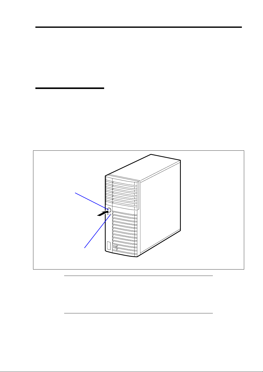
General Description 2-15
USING YOUR SERVER
This section describes basic operations of your server including how to use devices such as the
floppy disk drive and the optical disk drive. See Appendix B for notes on using the floppy disk,
CD-ROM, and accessories including the keyboard and the mouse.
POWER/SLEEP Switch
Use the POWER/SLEEP switch to turn on/off the server.
Power On
Press the POWER/SLEEP switch on the front of the server.
The POWER/SLEEP lamp lights in green.
POWER/SLEEP switch
POWER/SLEEP lamp
IMPORTANT:
If the power cord is connected to a power control device such as a
UPS (Uninterruptible Power Supply), make sure that the power
control device is powered.
Do not turn off the server until characters appear on the screen.
Page 46

2-16 General Description
POST
POST (Power On Self-Test) is the self-diagnostic program stored in the system memory.
When you power on the server, the system automatically runs POST to check the mother board,
ECC memory module, CPU module, keyboard, and mouse. POST also displays messages of the
BIOS Setup utility, such as the start-up message, while in progress.
With the factory setup of the server, the NEC logo appears on the display unit while POST is in
progress. (To display the POST check results, press Esc.)
NOTE: You can set the POST check results to appear on the display
unit without pressing Esc. To do so, select "Enabled" for "Boot-time
Diagnostic Screen" under the Advanced menu of the BIOS SETUP
utility.
You don't always need to check the POST check results. Check messages that POST displays when:
you use the NEC Express server for the first time.
the server appears to fail.
the server beeps for many times between power-on and OS start-up.
an error message appears on the display unit.
Page 47

General Description 2-17
POST Execution Flow
The following describes the progress of POST in the chronological order.
IMPORTANT:
Do not power off the server while POST is in progress.
Do not make key entries or perform mouse operations while POST
is in progress.
Some system configurations may display the message "Press Any
Key" to prompt a key entry. This message is driven by BIOS of an
installed optional board. Make sure to read the manual that comes
with the optional board before any key entry.
Powering on the server, after you installed or removed an optional
PCI board or moved it to another slot, may display the message that
indicates incorrect board configuration and suspend POST.
In such a case, press F1 to continue POST. Board configuration can
be made using the utility described later.
1. After a few seconds from power-on, POST starts checking the memory. The count
message of the basic and expansion memory appears at top left on the display unit screen.
The memory check may take a few minutes to complete depending on the memory size of
the server. Also, it may take approximately one minute for the screen display to appear
after rebooting the server.
2. Some messages appear upon completion of the memory check. These messages appear to
indicate that the system has detected the CPU, keyboard, and mouse.
3. After a few seconds, the following message appears at the bottom left of the screen
prompting you to launch the SETUP utility stored in the BIOS chip on the motherboard.
To launch the SETUP utility, press F2 while the above message is displayed.
Message displayed when the NEC logo appears:
Press <F2> to enter SETUP or Press <F12> to Network
Message displayed when the POST screen appears:
Press <F2> to enter SETUP <F10> Boot menu <F12> to boot from
Network
Launch the SETUP utility only when you need to change the settings to meet the
requirements of the server environment. As long as the above message is not accompanied
by an error message, you do not have to change the settings. (Ignore the message. POST
will continue a few seconds later.)
See Chapter 4 for setup and parameters.
Page 48

2-18 General Description
4. If your server uses Onboard RAID Controller, the following message is displayed to
prompt you to run RAID utility.
Press <Ctrl><M> to Run LSI SoftwareRAID Configuration Utility
Press Ctrl + M to run the utility. For detail explanation, see Chapter 4 for details.
IMPORTANT: The LSI Software RAID Configuration Utility is used
to manage the data stored in hard disk drive, or for maintenance. See
Chapter 4 for detail.
5. If the POST detects the optional add-in card, it displays the message prompting you to
launch the add-in card BIOS configuration utility. (Ignore the message. POST will
automatically proceed a few seconds later.)
Refer to the manual that comes with the optional add-in card for detail.
6. If you set a password entry using the BIOS SETUP utility, the password entry screen
appears upon successful completion of POST.
Up to three password entries will be accepted. Three incorrect password entries disable
the server to boot. In such a case, turn off the power and wait about ten seconds before
turning on to boot the server.
IMPORTANT: Do not set a password before installing an OS.
7. The OS starts when POST completes.
POST Error Messages
When POST detects an error, it displays an error message on the display unit screen or emits beep
code. See Chapter 8 for POST error codes.
IMPORTANT: Take a note on the messages displayed before
consulting with your sales agent. Alarm messages are useful
information for maintenance.
Page 49

General Description 2-19
Power Off
Follow the procedure below to power off the server. If the power cord of the server is connected to a
UPS, refer to the manual that comes with the UPS or the manual for the application that controls the
UPS.
IMPORTANT: Always allow POST to complete before turning off the
server.
8. Shut down the OS.
9. Press the POWER/SLEEP switch on the front of the server.
The POWER/SLEEP lamp goes out.
10. Power off peripheral devices.
SLEEP Switch
The POWER/SLEEP switch allows you to save almost all power of the server (power-saving mode
or sleep mode).
Press the POWER/SLEEP switch on the front of the server to place the server in the power-saving
mode. (The POWER/SLEEP lamp blinks.) In the power-saving mode, the server retains the memory
data and the status of the previous operations.
To resume the original state, press the POWER/SLEEP switch again. (It may take a little time to
resume the original state.)
NOTE: The operational level in the power-saving mode depends on
the OS in use. (Available for Windows Server 2003.)
IMPORTANT: Do not change system configuration while turning into
the power-saving mode or in the power-saving mode. Otherwise, you
may fail to resume the original state.
Page 50

2-20 General Description
Optical Disk Drive
The optical disk drive is installed in the front of the server. One of the following optical disk drives
can be used.
DVD-ROM drive (factory-installed)
Reads data from various optical disks.
DVD Super MULTI drive (option)
Reads or writes data of various optical disks.
CAUTION
Observe the following instructions to use the server safely. Failure to follow
these instructions may cause a fire, personal injury, or property damage. See
pages 1-2 to 1-11 for details.
Do not leave the tray ejected from the optical disk drive.
Precautions
Observe the following instructions when using the server. The server itself or your property (data
and other devices) might be destroyed if you use the server disregarding these instructions.
Use of the Optical Disk
Keep the following notes in mind to use the optical disk for the server:
For the disk which does not conform to the CD standard, the playback of such a disk with
the optical disk drive is not guaranteed.
Do not drop the optical disk.
Do not place anything on the optical disk or bend the optical disk.
Do not attach any label onto the optical disk.
Do not touch the signal side (nothing is printed on this side) with your hand.
Place the optical disk with its printed side upward and gently put it on the tray.
Do not scratch the optical disk or write anything directly on it with a pencil or ball-point
pen.
Keep the optical disk away from cigarette smoke.
Do not leave the optical disk in a high-temperature place (e.g., place exposed to direct
sunlight or close to a heater).
When dust or fingerprints are attached on the optical disk, wipe the optical disk from its
center to edge with a dry soft cloth slowly and gently.
Use the dedicated cleaner to clean the optical disk. Do not use record spray/cleaner,
benzene, or thinner.
Page 51

General Description 2-21
Keep the optical disk in an optical disk case when not in use.
Use a non-printable disk recommended in the User's Guide of the server and/or the device.
Optical disk is a data storage media with delicate structure and requires care. Clean the
tray and optical regularly according to "Cleaning Disc" in Chapter 7.
Writing Data onto Disk
After writing the data onto disk, be sure to perform data compare process.
An operator should always be concerned with data writing (unattended writing should not
be performed).
Handling of Optical Disk Drive
Do not leave the tray ejected from the optical disk drive.
Do not leave the drive with an optical disk being contained.
Clean the disk and drive in regular basis. For the slim type drive, be careful not to touch
the lens while cleaning the drive.
Make sure that the drive works normally by reading a disk such as NEC
EXPRESSBUILDER.
About Write Error
A write error might occur when writing a data by using the optical disk drive due to the operating
environment or characteristics of disk, etc.
If a write error occurs even after the cleaning, try another disk.
Before Writing onto Disk
It is prohibited by the law to reproduce audio CD and the application without the
permission of the writer except for the personal use.
The data stored in DVD-R, DVD+R, or CD-R may be destroyed partially or entirely due
to write error. To prevent the data loss, observe the following instructions.
– Quit the program including an application software that might consume a large amount
of memory.
– Disable the screen saver utility.
– Quit the program to check the disk such as virus checker or system agency.
– Disable the utility that might start during writing, such as scheduler or timer.
– Disable the power-saving feature in power management.
– Do not boot any application while writing.
Page 52

2-22 General Description
Writing/reading Time Fluctuation
The optical disk drive has a feature to detect the disk condition and determine the optimum writing
or reading speed for the disk. Accordingly, the time required for writing or reading data may not be
constant, depending on disk condition.
Page 53

General Description 2-23
Flash FDD
A Flash FDD is compatible with a floppy disk.
Only one Flash FDD can be connected to the USB connector of the server.
If a Floppy Disk Drive has been connected to the server, be sure to disconnect it.
CAUTION
Be careful so that the connected Flash FDD is not lost or stolen. Loss, theft, or
misappropriation of the Flash FDD, as well as fraud involving the Flash FDD,
might cause personal data to be leaked to third parties. NEC is not liable for
damage caused by such leakage.
IMPORTANT:
The status before connecting a Flash FDD to the server is applied to
its write protect switch. Therefore, changing this write protect
switch after connecting the Flash FDD to the server is ignored.
If it becomes necessary to change the write protect switch while
using the connected Flash FDD, disconnect the Flash FDD, and then
change the switch.
Be careful not to slide the Flash FDD write protect switch when
connecting or disconnecting the Flash FDD.
Precautions
Use a Flash FDD only for temporary purposes such as loading the device drivers during OS
installation. Do not use it to back up data.
Compensation for Saved Data
NEC is not liable for data saved in a Flash FDD and will not provide compensation if such data is
lost.
Handling the Flash FDD
Do not turn off the Flash FDD while the access LED of the unit is blinking. Doing so
might cause the Flash FDD to fail or corrupt data saved in it.
A Flash FDD is a consumable product. If an error occurs in a Flash FDD, use a new Flash
FDD instead of continuing to use the old one.
Be sure to connect a Flash FDD directly to a USB connector, not by way of a USB hub.
Before touching a Flash FDD, eliminate static electricity from your body by touching
metal such as a door knob or aluminum sash.
Page 54

2-24 General Description
Do not disassemble a Flash FDD.
Do not to shake or hit a Flash FDD.
Do not leave a Flash FDD in a place exposed to direct sunlight or close to a heater.
Do not handle a Flash FDD while eating, drinking, or smoking. Also, be careful not to get
thinner or alcohol on a Flash FDD.
Be careful when connecting a Flash FDD to the server.
Do not move a Flash FDD while it is connected to the USB connecter of the server. Doing
so might cause the Flash FDD to fail.
After using a Flash FDD, disconnect it from the server.
Page 55

Chapter 3
Setting Up Your Server
This chapter describes how to set up your server appropriate for your system, on a step-by-step
basis.
Page 56

3-2 Setting Up Your Server
SETUP FLOW
Follow the flowchart below to set up the server.
Unpacking the system
Unpack the server and accessories from the shipping carton box.
Installing optional devices
If you have purchased any optional device for the server, see Chapter 9 to install it.
Selecting the server site
Select a suitable site for the server.
Connecting peripheral devices
Connect peripheral devices to the server.
Connecting the power cord
Connect the power cord to the server.
Turning on the server
Power on the server to start software setups. Setups depend on the optional internal
devices installed and the peripheral devices connected.
Installing the operating system
Install an operating system to the server. See Chapter 5.
Installing the utilities
Install the utilities in the provided NEC EXPRESSBUILDER DVD.
See Chapter 6.
Making backup copies of system information
After all the system setup procedures are completed, make backup copies of system
information.
System information is required for recovering the server from the trouble or after
replacing the system board.
Page 57

Setting Up Your Server 3-3
UNPACKING THE SYSTEM
When you receive your system, inspect the shipping containers prior to unpacking. If the shipping
boxes are damaged, note the damage, and if possible, photograph it for reference. After removing
the contents of the containers, keep the cartons and the packing materials. If the contents appear
damaged when you unpack the boxes, file a damage claim with the carrier immediately.
INSTALLING OPTIONAL DEVICES
To install any optional device, see Chapter 9, "Upgrading Your Server," for the installation
procedure. Proceed to the next section if you have no optional devices to install.
IMPORTANT: There are third-party products (memory modules, hard
disk drives, etc.) available for the server in the markets. However, NEC
recommends that you should use NEC products for stable operation.
NEC assumes no liability for data errors and failures due to malfunction
of the server resulted from installation of those third-party products.
Page 58

3-4 Setting Up Your Server
SELECTING SERVER SITE
Read the following precautions before selecting a suitable site for your server. The following
describes installation of the server and connections to the server.
CAUTION
Observe the following instructions to use the server safely. Failure to follow
these instructions may cause a fire, personal injury, or property damage. See
pages 1-3 to 1-8 for details.
Never attempt to lift the server only by yourself.
Do not install the server in any place other than specified.
The following figure illustrates a site suitable for installing the server.
Room that satisfies the following
conditions: *
<While operating>
Temperature: 10 to 35ºC
Humidity: 20 to 80%
Temperature gradient: ±10ºC/h
Atmosphere: 749 to 1040 hpa
<While halting>
Temperature: –10 to 55ºC
Humidity: 10 to 80%
Temperature gradient: ±15ºC/h
Atmosphere: 749 to 1040 hpa
Allow clearance of at least 150 mm in
front of and behind the server.
Close enough to connect the
mouse and the display.
100 to 120 Vac/200 to 240
Vac parallel bi-polar wall
power outlet with the
ground line.
Install the server on
a flat, rigid desk
Clean and tidy room
* It is recommended that the server should be used in a room where
temperature is in the range between 15 to 25ºC.
Page 59

Setting Up Your Server 3-5
When you have selected a server site, hold the server by its bottom with at least three persons and
carry it to the site, then place it slowly and gently.
IMPORTANT: Do not hold the server by its front bezel to lift the
server. The front bezel may be disengaged and damage the server.
Do not install the server in the following locations as it may cause malfunctions of the server.
Places with drastic changes in temperature (e.g., near a heater, air conditioner, or
refrigerator)
Places with strong vibration
Places with corrosive gas in presence, near chemicals, or with possibilities of chemicals
sprayed over
On a non-antistatic carpet
Places with possibilities of falling objects
Places where a power outlet that shares the ground line with another (especially the one to
which a device with large power consumption is connected) must be used for the server
Do not install the server near equipment that generates power noise (e.g., contact spark at
power-on/power-off of commercial power supply through a relay). (To install the server
near equipment that generates power noise, ask your service representative for separating
the power wiring or installing a noise filter.)
Page 60

3-6 Setting Up Your Server
CONNECTING PERIPHERAL DEVICES
Connect peripheral devices to the server. The server is provided with connectors for wide variety of
peripheral devices. The figure on the next page illustrates available peripheral devices for the server
in the standard configuration and locations of the connectors for the devices.
Observe the following instructions to use the server safely. Failure to follow
these instructions may cause a fire, personal injury, or property damage. See
pages 1-3 to 1-8 for details.
Do not use any damaged cable connector.
Do not use any unauthorized interface cable.
Do not use the server with any loose interface connection.
Do not step on the interface cable or place any heavy object on it.
CAUTION
IMPORTANT:
Power off the server and a peripheral device before connection.
Connecting a powered peripheral device to the powered server will
cause malfunctions and failures.
To connect a third-party peripheral device or interface cable to the
server, consult with your service representative for availability of
such a device or cable. Some third-party devices may not be used
for the server.
To connect the provided keyboard and mouse, plug their connectors
to the server with the "Δ" mark on the connectors facing right.
Do not connect the serial ports with the telephone line directly.
Do not connect any devices to the connectors not instructed in this
subsection. Doing so could damage the device, your server, or both.
Page 61
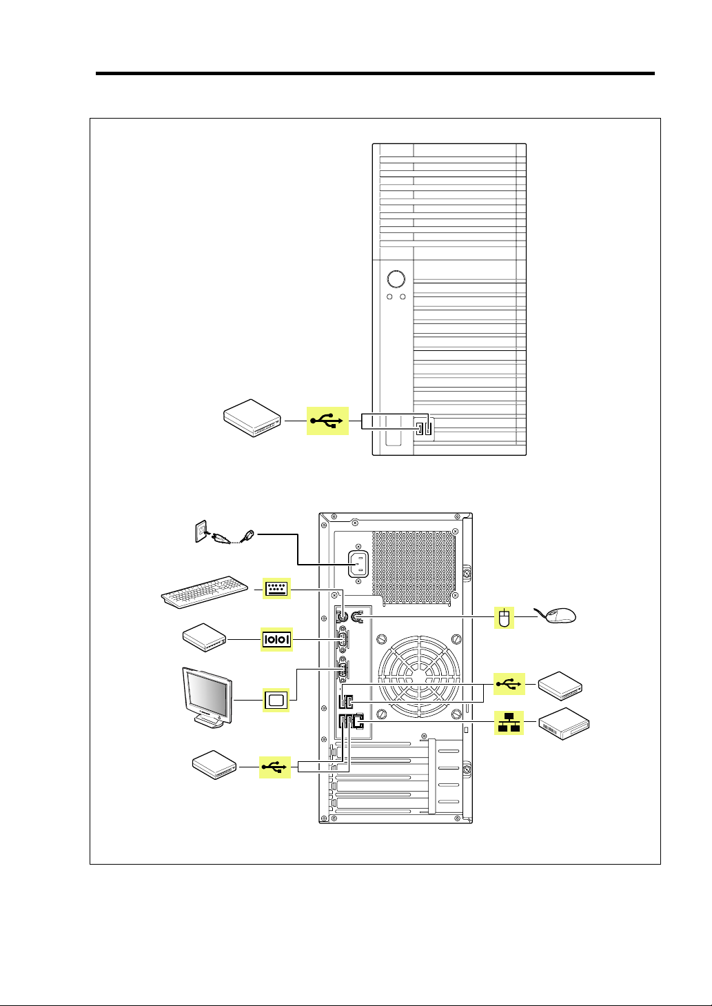
Setting Up Your Server 3-7
Device with the USB interface
(e.g., terminal adapter)
Finally, connect the power
cord to the receptacle.
Keyboard
Device with the serial interface
(e.g., modem)
Display unit
FRONT
Mouse
Device with the USB interface
(e.g., terminal adapter)
Hub/Switching hub
Device with the USB interface
(e.g., terminal adapter)
REAR
Page 62

3-8 Setting Up Your Server
CONNECTING POWER CORD
Connect the provided power cord to the server.
Observe the following instructions to use the server safely. Failure to follow
these instructions may result in death or serious personal injury. See pages 1-3
to 1-8 for details.
Do not hold the power plug with a wet hand.
WARNING
Observe the following instructions to use the server safely. Failure to follow
these instructions may cause a fire, personal injury, or property damage. See
pages 1-3 to 1-8 for details.
Do not plug the power cord in to an improper power source.
Do not connect the power cord to an outlet that has an illegal number of
connections.
Insert the power plug into the outlet as far as it goes.
Use the authorized power cord only.
CAUTION
1. Plug the provided power cord into the power receptacle on the rear of the server.
2. Plug the other end of the power cord into the wall outlet.
Page 63

Setting Up Your Server 3-9
NOTES:
To connect the power cord from the server to an uninterruptive
power supply (UPS), use service outlets on the rear of the UPS.
Refer to the manual that comes with the UPS for details.
When the power cord from the server is connected to a UPS, change
the BIOS SETUP utility of the server to link with power supply
from the UPS.
Change a parameter for "AC-LINK" of the Server menu of the
BIOS SETUP utility. See Chapter 4 for details.
Page 64

3-10 Setting Up Your Server
TURNING ON THE SERVER
Turn on the server and follow the on-screen instructions for setup.
1. Make sure all external devices, such as a video display, keyboard, and mouse have been
connected, and the power cords are connected.
2. Power on the video display and any other external devices.
3. Make sure that the floppy disk drive contains no floppy disk and the optical disk drive
contains no bootable DVD/CD-ROM.
4. Press the POWER/SLEEP switch.
NOTES:
If the power cord is connected to the power control unit such as the
UPS, turn on the power control unit.
Connect the power cord and wait a few seconds before pressing the
POWER/SLEEP switch. The POWER/SLEEP switch does not work
in a few seconds after connecting the power cord due to firmware
start-up.
POWER/SLEEP switch
POWER/SLEEP lamp
Page 65

Setting Up Your Server 3-11
The POWER/SLEEP lamp on the front of the server comes on.
In a few seconds, the NEC logo appears on the screen and the Power On Self-Test (POST) begins.
The POST runs automatically when you power on the server or reset it with a keyboard operation
(Ctrl + Alt + Delete). The POST runs diagnostics, initializes the server, sets interrupt vectors,
detects installed peripheral devices, and boots the operating system (if installed). See Chapter 2 for
detailed description on POST.
If the server halts before completing the POST, the POST emits a beep code indicating a fatal
system error requiring immediate attention. (See Chapter 8, "Troubleshooting," for troubleshooting
information.)
During memory test, the POST displays the amount of memory it was able to access and test.
Depending on the amount of installed memory, it may take several minutes to complete the memory
test.
NOTE: The factory-set is defined to hide the POST screen with the
NEC logo screen. You can always change the NEC logo screen to the
POST screen by pressing Esc. To change the start-up screen, use the
BIOS SETUP utility. (See Chapter 4 for details.)
During the POST, you will see the banner message to prompt you to launch the BIOS SETUP utility
stored in ROM on the mother board or on an installed option board.
Start the BIOS SETUP utility appropriate to your system environment to change the CMOS Setup.
For detail explanation on the BIOS SETUP utility for the server, see Chapter 4. For the BIOS utility
for the option board, refer to the manual that comes with the option board.
IMPORTANT: Always allow POST to complete before turning off
your system.
Page 66

3-12 Setting Up Your Server
INSTALLING OPERATING SYSTEM
See Chapter 5 for installing Microsoft Windows Server 2008 and Microsoft Windows Server 2003.
To install the other operating system listed above, contact your service representative.
IMPORTANT: Use NEC EXPRESSBUILDER for initial setup of
your server. The NEC EXPRESSBUILDER is support software for the
server. It simplifies the process of installing and configuring your server.
See Chapter 6 for details on NEC EXPRESSBUILDER.
INSTALLING UTILITIES
Install the utilities that come with the server. See Chapter 6 for details.
MAKING BACKUP COPIES OF SYSTEM INFORMATION
The system information includes the current BIOS settings and any specific information for the
server.
Save the information after completing the system setup.
Without the backup data, you will not be able to recover the information.
You can save the information by the following process.
1. Connect Flash FDD or USB FDD to the USB connector.
2. Insert the NEC EXPRESSBUILDER DVD into the optical disk drive and reboot the
system.
3. Select [Tool menu (Normal mode)].
4. Select [English].
5. Select [Maintenance Utility].
6. Select [System Information Management].
7. Select [Save].
Page 67

Chapter 4
Configuring Your Server
Configuration and setup utilities are used to change your system configuration. You can configure
your system, as well as option boards you may add to your system, using the BIOS SETUP Utility.
Several unique system parameters are configured using the BIOS SETUP, which is stored in the
system FLASH memory.
The RAID configuration utility configures the RAID System and logical drives connected to the
Onboard RAID Controller or optional RAID Controller.
If your system has been factory configured, the BIOS SETUP or RAID configuration utility do not
need to be run unless you want to change the password or security features, add certain types of
option boards or devices, upgrade your system board, or change the RAID configuration.
This chapter also provides information on several system configuration parameters that are set by
jumpers on the system board. However, these parameters do not usually require change.
Page 68

4-2 Configuring Your Server
SYSTEM BIOS (BIOS SETUP UTILITY)
The BIOS Setup utility is provided to make basic hardware configuration for the server. This utility
is pre-installed in the flash memory of the server and ready to run.
The server is configured with the correct parameters using the BIOS Setup utility and shipped in the
best conditions. Thus, you don't need to use the BIOS Setup utility in most cases. However, you
might wish to use the BIOS Setup utility in the cases described below.
IMPORTANT:
The BIOS Setup utility is intended for system administrator use
only.
The BIOS Setup utility allows you to set a password. The server is
provided with two levels of password: Supervisor and User. With
the Supervisor password, you can view and change all system
parameters of the BIOS Setup utility. With the User password,
system parameters available for viewing and changing are limited.
Do not set any password before installing the OS.
The server contains the latest version of the BIOS Setup utility.
Dialog boxes appear on your BIOS Setup utility, thus, may differ
from descriptions in this manual. If you find anything unclear, see
the online help or ask your service representative.
Page 69

Configuring Your Server 4-3
Starting SETUP Utility
When you turn on the server, the NEC logo appears first. (The POST (Power On Self-Test) screen
might appear first, depending on the SETUP settings.)
The following message then appears at bottom left of the screen.
Message displayed when the NEC logo appears:
Press <F2> to enter SETUP or Press <F12> to Network
Message displayed when the POST screen appears:
Press <F2> to enter SET UP <F10> Boot menu <F12> to b oot from
Networ k
If you press F2 while the above message is displayed, the SETUP utility will launch and its main
menu will be displayed.
If you have previously set a password with the BIOS Setup utility, the password entry screen
appears. Enter the password.
Enter password:[ ]
Up to three password entries will be accepted. If you fail to enter the password correctly for three
consecutive times, the server halts. (You can no longer proceed.) Power off the server.
NOTE: The server is provided with two levels of password:
Administrator and User. With the Administrator password, you can
view and change all system parameters. With the User password,
system parameters available for viewing and changing are limited.
Page 70

4-4 Configuring Your Server
Description on On-Screen Items and Key Usage
Use the following keyboard keys to work with the BIOS Setup utility. These keys are also listed at
the bottom of the menu screen.
Indicates there
are submenus.
Setup
item
menu
Indicates the current menu.
Online
help
window
Explanation of key functions menu
Parameter (high-lights upon selection) menu
Cursor (↑, ↓):
Cursor (←, →):
– and +:
Enter
Esc
F1:
F9:
F10:
Move cursor up and down. The cursor moves only to the settings
that you can change.
Move between menus.
Select the previous value (–) or the next value (+) for the field.
Execute command or select Æ submenu.
Exit the current menu and return to the previous menu.
Get Help about an item.
Load default configuration values for this menu.
Save configuration values and exit.
Page 71

Configuring Your Server 4-5
Configuration Examples
The following describes examples of configuration required to use software-link features or for
system operations.
Time and Date Settings
You can also change the time and date settings via the operating system commands.
Select [Main] - [System Time].
Select [Main] - [System Date].
Link with Management Software
To control power supply of the server with NEC ESMPRO Manager via the network
Select [Advanced] - [Advanced Chipset Control] - [Wake On LAN/PME] - [Enabled].
Select [Server] - [AC LINK] - [Stay Off].
Hard Disk Drive
To check the hard disk drive status
Select [Main] - [SATA Port 0/1/2/3/4/5] and check the status indications.
UPS
To link power supply with the UPS
To power on the server when power is supply from the UPS
Select [Server] - [AC LINK] - [Power On].
To keep the server off-powered even when power is supplied from the UPS
Select [Server] - [AC LINK] - [Stay Off].
Boot
To check the boot order
Select [Boot] and check the current boot order.
To change the boot order of devices connected to the server
Select [Boot] and specify the boot order.
IMPORTANT: If you have installed any bootable device, be sure to
run BIOS Setup menu to check the boot priority on [Boot] menu. If the
bootable device is displayed in "Excluded from boot order", put the
cursor onto the device, then press x to move it to "Boot priority order".
Page 72

4-6 Configuring Your Server
Memory
To check the installed memory (DIMM board) status
Select [Advanced] - [Memory Configuration] and check the status indications.
The on-screen DIMM group numbers and socket locations on the mother board are
associated as shown in the following figure.
DIMM #2
DIMM #4
DIMM #1
DIMM #3
To clear the memory (DIMM board) error information
Select [Advanced] - [Memory Configuration] - [Memory Retest] - [Yes] and reboot.
To run power-on memory test
Select [Advanced] - [Memory Configuration] - [Extended RAM Step] - [1MB] and
reboot.
CPU
To check the installed CPU status
Select [Main] - [Processor Settings] – [Processor CPUID] and check the status
indications.
Page 73

Keyboard
To set Numlock
Select [Advanced] - [Numlock] – [On]/[Off].
Security
To set passwords on the BIOS
Select [Security] - [Set Supervisor Password] and enter a password.
Select [Security] - [Set User Password] and enter a password.
Set Supervisor password first, then User password.
External Devices
To set up external devices
Select [Advanced] - [Peripheral Configuration] and set up each device.
Internal Devices
To install the RAID Controller card or SCSI controller card
Select [Advanced] - [PCI Configuration] - [PCI Slot n Option ROM] - [Enabled].
n: slot number
Configuring Your Server 4-7
To clear the hardware configuration data (after installing/removing internal devices)
Select [Advanced] - [Reset Configuration Data] - [Yes] and reboot.
Running the Server with the Fan Low-speed (Silent) Mode)
To run the server with the fan set to low-speed (silent) mode
Select [Server] - [Fan Control Mode] - [Low].
If a board is inserted in the server’s PCI slot, the fan cannot be set to low-speed (silent)
mode.
Saving the Configuration Data
To save the current configuration data and exit from SETUP
Select [Exit] - [Exit Saving Changes].
To discard changes to the current configuration data and exit from SETUP
Select [Exit] - [Exit Discarding Changes].
To load the default setup
Select [Exit] - [Load Setup Defaults].
To discard changes to the current configuration data
Select [Exit] - [Discard Changes].
Page 74

4-8 Configuring Your Server
To save the current configuration data
Select [Exit] - [Save Changes].
Page 75

Configuring Your Server 4-9
Menu and Parameter Descriptions
The SETUP utility has the following six major menus:
Main
Advanced
Security
Server
Boot
Exit
To set minute functions, select a submenu from the above menus. The following describes available
functions and parameters, as well as the factory-set, for each menu.
Page 76

4-10 Configuring Your Server
Main
Option Parameter Description Your Setting
System Time HH:MM:SS Set the system time.
System Date MM/DD/YYYY Set the system date.
Hard Disk Pre-Delay [Disabled]
3 seconds
6 seconds
9 seconds
12 seconds
15 seconds
21 seconds
30 seconds
SATA Port 0
SATA Port 1
SATA Port 2
SATA Port 3
SATA Port 4
SATA Port 5
Processor Settings –
Language [English (US)]
[ ]: Factory-set
–
Français
Deutsch
Español
Italiano
When accessing the IDE device
for the first time during POST,
the system waits for the
specified time until the device
becomes ready.
Shows the information on the
device connected to each
channel on the submenu. The
settings of some items may be
changed. However, leave the
items as they are at the
shipment.
Shows the processor settings
submenu.
Select which language BIOS
displays.
IMPORTANT:
operation if any of the following conditions is applicable.
After carriage of device
After storage of device
After the device is entered into the pause state under the
environmental condition enduring device operation (temperature:
10°C - 35°C, humidity: 20% - 80%)
Check the system clock at the rough rate of once per month. When the
system clock is installed in a system requiring high time precision, it is
recommended to use a time server (NTP server).
Check and adjust the system clock before the
If the system clock is remarkably delayed or advanced as the passage of
time in spite of adjustment, contact your service representative for
maintenance.
Page 77

Configuring Your Server 4-11
Processor Settings
Option Parameter Description Your Setting
CPU Speed – Displays clock speed for the
processor. (View only)
Processor CPUID Numeral (xxxx) Displays the processor ID.
(View only)
Processor L2 Cache – Displays L2 cache size for
processor.
Processor L3 Cache – Displays L3 cache size for
processor.
Active Processor Cores [ALL]
1
2
Execute Disable Bit [Enabled]
Disabled
Intel SpeedStep(R)
Technology
Turbo Boost
Technology
C1 Enhanced Mode [Enabled]
Processor C3 Report Disabled
Virtualization
Technology
[ ]: Factory-set
[Enabled]
Disabled
[Enabled]
Disabled
Disabled
ACPI C2
[ACPI C3]
[Enabled]
Disabled
Specifies the number of valid cores
in the processor.
Enables or disables the Execute
Disable Bit feature.
Displayed only when the CPU
supports Execute Disable Bit.
Enables or disables the Intel(R)
SpeedStep feature.
Fixed to "Disabled" if the processor
does not support this feature.
Enables or disables the Intel(R)
Turbo Boost Technology. Displayed
only when the CPU supports this
feature.
Enables or disables the C1
Enhanced Mode.
Specifies the ACPI state to which
the C3 state of the processor is
mapped.
Enables or disables the Intel(R)
virtualization technology.
Page 78

4-12 Configuring Your Server
Advanced
Option Parameter Description Your Setting
Boot-time Diagnostic
Screen
Reset Configuration Data [No]
NumLock On
Memory Error [Boot]
[ ]: Factory-set
Enabled
[Disabled]
Yes
[Off]
Halt
When enabled, the BIOS will display
the POST progress.
When disabled, the BIOS will
display the NEC logo during POST.
Cannot be disabled during console
redirection.
Select "Yes" if you want to clear the
system configuration data during the
next boot. Automatically reset to
"No" in the next boot.
Enables or disables Numlock
feature at system startup.
This option is used to specify
whether the system stops at the end
of POST when a memory error has
been detected during POST.
This option is enabled when [POST
Error Pause] on the [Server] menu
is set to [Enabled]. If there is no
usable memory in the system, the
system will stop at the end of POST
even if [Boot] is specified for this
option.
IMPORTANT: Be sure to take a note of boot priority before selecting
"Yes" for [Reset Configuration Data], because the information on boot
device will be cleared. Select [Exit Saving Changes] to restart the
system, run BIOS SETUP utility, and provide settings for boot device
order again.
Page 79

Configuring Your Server 4-13
Memory Configuration
Option Parameter Description Your Setting
Installed memory –
Available under
4GB
DIMM1-4 Status Normal
Memory Retest Yes
Extended RAM
Step
[ ]: Factory-set
–
Disabled
Not installed
Error
[No]
1MB
[Disabled]
Indicates the total capacity of the base
memory. (View only)
Indicates the capacity of memory
available in the area under 4GB. (View
only)
Indicates the current memory status.
"Normal" indicates the normal status,
"Disabled" indicates a memory error, "Not
installed" indicates no DIMM installed,
and
"Error" indicates the system is forcibly
started with memory error. (View only).
Causes BIOS to retest all memory on the
next boot. Automatically reset to "No" at
the next boot.
"1MB" indicates that the memory test is
done in the unit of 1MB.
"Disabled" indicates that only memory
initialization is done.
Only pressing Space is acceptable to
suspend the test during the memory test.
PCI Configuration
Option Parameter Description Your Setting
PCI Slot 1-4
Option ROM
[ ]: Factory-set
[Enabled]
Disabled
Displays the submenu to specify whether to
enable or disable the BIOS on the device
(board) connected to PCI slot.
Set this item to "Enabled" when the RAID
Controller or SCSI controller is connected
with the hard disk drive which contains an
OS.
Set this item to "Disabled" when the LAN
controller which contains ROM BIOS is
used but the board does not provide
network booting.
Disabling Option ROM Scan saves memory
consumption and time for startup.
IMPORTANT: If the RAID Controller, LAN board (network boot), or
SCSI controller is connected with the hard disk drive that does not
contain an OS, set the parameter for "PCI Slot x Option ROM" (x: slot
containing the PCI card) to "Disabled".
Page 80

4-14 Configuring Your Server
PCI Device, Onboard VGA
Option Parameter Description Your Setting
Onboard VGA
Option ROM Scan
[ ]: Factory-set
[Auto]
Force
Selects whether the option ROM of
onboard video controller is executed
automatically for forcedly.
When [Auto] is selected, the ROM of the
VGA card is preferentially scanned.
PCI Device, Onboard Lan
Option Parameter Description Your Setting
LAN Controller Disabled
[Enabled]
LAN Option ROM
Scan
[ ]: Factory-set
Disabled
[Enabled]
Enables or disables onboard LAN
controller.
Enables or disables an option ROM of
onboard LAN controller.
Peripheral Configuration
IMPORTANT: Note that the interrupt and/or base I/O address are not
overlapped with others.
Option Parameter Description Your Setting
Serial Port A Disabled
[Enabled]
Base I/O
address
Interrupt IRQ 3
Serial Port B Disabled
Base I/O
address
Interrupt [IRQ 3]
SATA RAID
Enable
[ ]: Factory-set
[3F8h]
2F8h
3E8h
2E8h
[IRQ 4]
[Enabled]
3F8h
[2F8h]
3E8h
2E8h
IRQ 4
[Disabled]
Enabled
Selects whether serial port A is enabled or
disabled.
Selects the base I/O address for serial port
A.
Selects the interrupt for a serial port A.
Selects whether serial port B is enabled or
disabled.
Selects the base I/O address for serial port
B.
Selects the interrupt for a serial port B.
Indicates whether the RAID disk drives that
uses the onboard SATA is enabled or
disabled. (View only)
To enable or disable the RAID system, use
the jumper switch on mother board.
Page 81

Configuring Your Server 4-15
Advanced Chipset Control
Option Parameter Description Your Setting
Multimedia Timer Disabled
[Enabled]
Intel(R) VT-d Disabled
[Enabled]
Wake On
LAN/PME
Wake On Ring [Disabled]
Wake On RTC
Alarm
[ ]: Factory-set
Disabled
[Enabled]
Enabled
[Disabled]
Enabled
Specify whether the system supports
the multimedia timer feature.
Specify whether the Intel(R)
Virtualization Technology for Directed
I/O feature is enabled or disabled.
This item appears only when the
processor supports this feature.
Specify whether the remote power-on
function through a network is enabled
or disabled.
Specify whether the remote power-on
function through a serial port (modem)
is enabled or disabled.
Specify whether the remote power-on
function that uses the RTC alarm
feature is enabled or disabled.
Set this option to [Enabled] to shift
from standby mode to sleep mode
after a specified time has elapsed by
using the OS power control function.
IMPORTANT: If the AC power is turned off while the Wake On Ring
feature is enabled, this feature is disabled at the next system boot after
AC power-on. You need to press the Power switch to boot the system. If
the AC power is turned off, Wake On Ring feature on power
management chip is disabled until the next DC power-on.
Page 82

4-16 Configuring Your Server
Security
Press Enter on "Set Supervisor Password" or "Set User Password," to display the password entry
screen.
Enter the passwords on the dialog box.
IMPORTANT:
User password can be set only when Supervisor password is already
set.
Set the passwords only after OS is installed.
If you forget the passwords, contact your service representative.
Option Parameter Description Your Setting
User
Password Is
Supervisor
Password Is
Set Supervisor
Password
Set User
Password
Password on
boot
Fixed disk boot
sector
Disable USB
Port
[ ]: Factory-set
Clear
Set
Clear
Set
Up to eight
alphanumerics
Up to eight
alphanumerics
[Disabled]
Enabled
[Normal]
Write Protect
[Disabled]
Front
Rear
Internal
Front + Rear
Front + Internal
Rear + Internal
Front + Rear + Internal
Indicates the user password setting
status.
Indicates the supervisor password
setting status.
Press Enter to display the
supervisor password entry screen.
This password enables all the
SETUP menus to be accessed. This
setting can be done only on login
with the password input of
"Supervisor" at start of SETUP.
Press Enter to display the user
password entry screen. For this
password, accessing to the SETUP
menu is restricted.
This setting can be done only on
login with the password input of
"Supervisor" at start of SETUP.
Specify whether the passwords are
entered or not on booting. At first,
the supervisor password must be
set. If the supervisor password is set
and this option is disabled, BIOS
determines that a user is booting.
Specify whether to permit writing
into boot sector of the IDE hard disk
drive or not. The server does not
support IDE hard disk drive.
Select the USB port to be disabled
or enabled.
Page 83

Configuring Your Server 4-17
Server
Option Parameter Description Your Setting
FRB-2 Policy Disable FRB2 Timer
[Retry 3 Times]
Always Reset
Boot Monitoring [Disabled]
5 Minutes
10 minutes
15 minutes
20 minutes
25 minutes
30 minutes
35 minutes
40 minutes
45 minutes
50 minutes
55 minutes
60 minutes
Boot Monitoring
Policy
Post Error
Pause
AC-LINK Stay Off
Fan control
Mode
[ ]: Factory-set
[Retry 3 Times]
Always Reset
Disabled
[Enabled]
[Last State]
Power On
[Normal]
Low
Specify the operation of the processor
when FRB level 2 error occurred in
BSP.
Specify whether to enable or disable
the boot monitoring function on
booting, or select the time limit for
timeout.
Specify the processing at the
occurrence of timeout during boot
monitoring.
If [Retry 3 times] is selected, the
system is reset after the occurrence of
timeout and OS boot is retried up to
three times.
If [Always Reset] is selected, the
system is reset after the occurrence of
timeout and OS boot is retried
repeatedly.
Specify whether to stop the POST
once at the end of POST if an error
occurs during the POST.
Specify the state of power when the
AC power to the server is turn off
once and then on.
If the silent mode available on the
system, specifying [Low] lets the
system enter into the silent mode
where rotation of fans are controlled.
Page 84

4-18 Configuring Your Server
The table below shows the operation when the AC power to the server is turn off once and then on
again, depending on the setting of "AC LINK."
System status before AC power off
Operating Off On On
Aborting (DC power being off also) Off Off On
Forced shutdown Off Off Off
* Press the POWER/SLEEP switch continuously for four seconds or longer. This forcibly
turns off the power. After this operation, the system does not turn on the power even
though the AC-LINK setting is set to Power On.
Setting of AC LINK
Stay Off Last State Power On
IMPORTANT:
To power on the server from the UPS (Uninterruptible Power
Supply), select [Server] - [AC Link] - [Power On].
If the server is connected to the UPS, set at least 10 seconds delay in
the power-on schedule.
Page 85

Configuring Your Server 4-19
System Management
Option Parameter Description Your Setting
BIOS Version –
Board Part Number –
Board Serial Number –
System Part Number –
System Serial Number –
Chassis Part Number –
Chassis Serial Number –
Onboard LAN MAC
Address
GBIA Module Version –
[ ]: Factory-set
–
Displays the current BIOS version.
(View only)
Displays the part number of mother
board. (View only)
Displays the serial number of mother
board. (View only)
Displays the part number of the
system. (View only)
Displays the serial number of the
system. (View only)
Displays the part number of the
chassis. (View only)
Displays the serial number of the
chassis. (View only)
Displays the MAC address of the
onboard LAN port 1. (View only)
Displays the current GBIA version.
(View only)
Page 86

4-20 Configuring Your Server
Console Redirection
Option Parameter Description Your Setting
Console
Redirection
Baud Rate 9600
Flow Control None
Terminal Type PC ANSI
Continue
Redirection after
POST
Remote Console
Reset
[ ]: Factory-set
[Disabled]
Serial Port A
Serial Port B
[19.2K]
38.4K
57.6K
115.2K
Xon/Xoff
[CTS/RTS]
[VT100+]
VT-UTF8
Disabled
[Enabled]
[Disabled]
Enabled
Specify the address/interrupt of the
serial port to which a remote console
is connected.
Specify the baud rate used for the
interface with the remote console
connected.
Specify the flow control method.
Specify the type of remote console.
Specify whether to continue console
redirection feature after completion of
POST.
Specify whether to enable or disable
resetting by Escape command (Esc
R) sent from the remote console.
If the server is connected with the
management PC that uses NEC
ESMPRO Manager, this option is
always enabled even if "Disabled" is
specified here.
DMI Event Logging
Option Parameter Description Your Setting
Event log validity –
Event log
capability
View DMI event
log
Event logging [Enabled]
Clear all DMI
event logs
[ ]: Factory-set
–
–
Disabled
[No]
Yes
Displays the status of event logs
stored in the system.
Displays the free space for storing
event logs.
Press Enter to display the event logs
stored in the system. See Chapter 8
“Troubleshooting” for the meanings of
the event logs and the recommended
action to take.
Specify whether to store the event log
or not.
When set to [Yes] and reboot the
system, the stored event logs are
cleared.
Page 87

Configuring Your Server 4-21
Boot
If you move the cursor to the position of "Boot," the Boot menu appears, which is used to set the
boot priority.
Indication Device
USB CDROM USB CD-ROM drive
IDE CD ATAPI CD-ROM
USB FDC Flash FDD or USB FDD
USB KEY USB flash memory device
IDE HDD IDE hard disk drives
PCI SCSI
USB HDD USB hard disk drive
PCI BEV IBA GE Slot xxxx: Onboard LAN
Internal hard disk drives installed in your system ("Software RAID" is
displayed in the RAID configuration.)
Other indication: Optional PCI board.
1. When BIOS detects a bootable device, it displays the information on the device in the
relevant indication.
To boot the server from a desired device, the device must be registered as a boot device.
(Up to eight boot devices can be registered.)
2. Pressing X after selecting a device allows the selected device to be registered as a boot
device or deleted from the registration.
With eight boot devices being registered, any other device cannot be registered as a boot
device even if you press X. To register a device as a boot device newly, first delete the
registration of a device registered as a boot device but not booted any more.
3. You can change the boot priority (first to eighth) of each device by using ↑, ↓, + and/or –.
To change the priority of a device, move the cursor to the device by using the ↑ or ↓, and
press + or –.
Page 88

4-22 Configuring Your Server
Exit
The options on the menu are described below.
Exit Saving Changes
Exit after writing all modified BIOS SETUP item values to CMOS.
Exit Discarding Changes
Exit leaving CMOS unmodified. User is prompted if any of the setup fields were modified.
Load Setup Defaults
Load default values for all BIOS SETUP items.
Discard Changes
Read the previous values of the all BIOS SETUP items from CMOS.
Save Changes
Write all BIOS SETUP item values to CMOS.
Page 89

Configuring Your Server 4-23
RAID SYSTEM CONFIGURATION
This section describes how to use the internal hard disk drives as RAID System by Onboard RAID
Controller (LSI Embedded MegaRAID™).
About the optional RAID Controller (N8103-109/116A/117A), refer to the documents provided
with optional RAID Controller.
IMPORTANT: When Onboard RAID Controller (LSI Embedded
MegaRAID™) or Optional RAID Controller (N8103-109/116A/117A)
is used, do not let the system enter hibernation or standby mode.
RAID
Overview of RAID System
What is RAID (Redundant Array of Inexpensive Disks)?
RAID is an abbreviation for "Redundant Array of Inexpensive Disks". The RAID technology allows
more than one hard disk drive (HDD) to be handled collectively.
In actual, RAID can configure more than one HDDs as a single disk array (disk group) to operate
the HDDs effectively. This can bring higher performance than a single HDD of a large capacity.
The Onboard RAID Controller (LSI Embedded MegaRAID™) has a feature to divide a single disk
group into several logical drives (virtual disks). Operating system recognizes these logical drives as
if it were a single hard disk drive. Operating system accesses to more than one hard disk drive
configuring a disk group in parallel.
Some RAID levels can recover data from remaining data and parity by using rebuild feature if an
error occurs in a single HDD. This can provide high reliability for the system.
Page 90

4-24 Configuring Your Server
RAID Levels
The record mode enabling the RAID feature includes several levels. Among the levels, the Onboard
RAID Controller (LSI Embedded MegaRAID™) supports RAID levels 0, 1, and 10. The number of
hard disk drives required to create a disk group varies depending on the RAID level as shown in the
table below.
RAID level
RAID 0 1 4
RAID 1 2 2
RAID 10 4 4
Number of required HDDs
Min. Max.
NOTE: For details of the RAID levels, see "RAID Levels" described
later in this chapter.
Disk Group
A disk group is configured with more than one HDDs.
The allowable number of disk groups is equal to the number of HDDs.
The figure below shows a sample configuration. The three HDDs are connected to the Onboard
RAID Controller (LSI Embedded MegaRAID™), creating one disk group (DG).
RAID Controller
Disk Group 0: 160 GB
HDD 1
(80 GB)
HDD 2
(80 GB)
Page 91

Configuring Your Server 4-25
Virtual Disk
Virtual disk is a logical drive defined in disk group. It is recognized as a physical drive by OS. The
allowable number of virtual disks is up to 8 per disk group, or up to 8 per controller.
The figure below shows a sample configuration in which the Onboard RAID Controller (LSI
Embedded MegaRAID™) is connected with two HDDs, creating one Disk Group. Two RAID1
virtual disks (VD) are defined in the Disk Group.
RAID Controller
DG0 160 GB
VD0-1
50GB
VD1-1
30GB
HDD 1
(80 GB)
VD0-2
50GB
VD1-2
30GB
HDD 2
(80 GB)
VD0 (RAID1)
50 GB
VD1 (RAID1)
30 GB
Hot-Spare
The hot-spare is prepared as an auxiliary HDD substituting for a defected HDD included in a disk
group which is configured at a redundant RAID level. Detecting a HDD fault, the system
disconnects the HDD (or makes it offline) and starts rebuild using the hot-spare.
Page 92

4-26 Configuring Your Server
RAID Levels
This section describes RAID levels that the Onboard RAID Controller (LSI Embedded
MegaRAID™) supports. The available RAID levels are RAID0, RAID1, and RAID10 (striping of
RAID1).
Characteristics of RAID Levels
The table below lists the characteristics of the RAID levels.
Level Function Redundancy Characteristics
RAID0 Striping No • Data read/write at the highest rate
• Largest capacity
• Capacity: (capacity of single HDD) ×
(number of HDDs)
RAID1 Mirroring Yes • Two HDDs required
• Capacity: capacity of single HDD
RAID10 Striping of RAID1 Yes • Four or more HDDs required
• Capacity: (capacity of single HDD) ×
((number of HDDs) / 2)
RAID0
In RAID0, data to be recorded is distributed to HDDs. The mode is called "striping".
In the figure below, data is recorded in stripe 1 (disk 1), stripe 2 (disk 2), and stripe 3 (disk 3)… in
the order. Because RAID0 allows all HDDs to be accessed collectively, it can provide the best disk
access performance.
IMPORTANT: RAID0 cannot have data redundancy. If a HDD is
defected, the data saved in the HDD cannot be recovered.
RAID Controller
HDD 1 HDD 2
Stripe 1
Stripe 4
Stri pe 2
Stri pe 5
HDD 3
Stri pe 3
Stri pe 6
Page 93

Configuring Your Server 4-27
RAID1
In the RAID1 level, data saved in a HDD is written to another HDD without change. The mode is
called "mirroring".
When data is written onto a single HDD, the same data is written onto another HDD. If either of the
HDDs is defected, the other HDD containing the same data can substitute for the defected HDD.
Thus the system can continue to operate without interruption.
RAID Controller
HDD 1 HDD 2
Stripe 1
Stripe 2
Stripe 1
Stripe 2
RAID10
Data to be recorded is distributed to two HDDs in mirroring mode. Then, each mirrored data is
written onto HDD by striping. Owing to this feature, high disk access performance of RAID0 and,
in addition, high reliability of RAID1 can be achieved.
RAID Controller
HDD 1 HDD 2
Stri pe 1
Stri pe 3
Stri pe 5 Stripe 5 St rip e 6
RAID1 RAID1
Stripe 1
Stripe 3
HDD 3
Stripe 2
Stripe 4
HDD 4
Stripe 2
Stripe 4
Stripe 6
RAID0
Page 94

4-28 Configuring Your Server
Configuration by Onboard RAID Controller
This section describes how to use the internal hard disk drives as RAID System by Onboard RAID
Controller (LSI Embedded MegaRAID™).
Installing the Hard Disk Drives
Install the required number of hard disk drives for the desired RAID level to your server. See
Chapter 9 for installation procedure.
IMPORTANT: Use hard disk drives of the same revolution. In
addition, use two hard disk drives of the same capacity if you are going
to configure RAID1.
Enabling RAID Feature
To configure a hard disk drive as RAID System, change the RAID System configuration jumper
switch on mother board.
WARNING
Observe the following instructions to use the server safely. Failure to follow
these instructions may result in death or serious personal injury. See pages
1-3 to 1-8 for details.
Do not disassemble, repair, or alter the server.
Do not remove the lithium battery.
Observe the following instructions to use the server safely. Failure to follow
these instructions may result in death or serious personal injury. See pages 1-3
to 1-8 for details.
Make sure to complete board installation.
Do not install the server on a rack with leaving covers removed.
Do not pinch your finger with mechanical components.
Note high temperature.
Do not pull out a device from the rack if the rack is unstable.
Do not leave more than one device being pulled out from the rack.
CAUTION
Page 95

Configuring Your Server 4-29
1. See the section "Preparing for Installation and Removal" as described in Chapter 9 of this
guide to prepare.
2. Remove the side cover (see Chapter 9).
3. Locate the position of the RAID configuration jumper on the mother board as shown
below.
Mother board
NOTES:
RAID configuration jumper switch
(SWRAID)
non-RAID
RAID
The factory setting of the RAID configuration jumper switch
depends on your order.
If you are using an Optional RAID Controller, set the RAID
configuration jumper switch to the position "non-RAID".
4. Install the side cover removed in Step 2.
Then, configure the RAID system by using the LSI Software RAID Configuration Utility.
Page 96

4-30 Configuring Your Server
Setup Utility
This section describes the RAID configuration tool, LSI Software RAID Configuration Utility.
Running LSI Software RAID Configuration Utility
When the following screen appears after you have powered on the server, press Esc.
1.
The POST screen appears.
2. Check the description as shown below on the POST screen, then press Ctrl + M.
LSI Software RAID Configuration Utility starts.
LSI SoftwareRAID BIOS Version xxxxxx
LSI MPT RAID Found at PCI Bus No:xx Bev No:xx
Scanning for port 00 Responding xxxxxxxx xxxxMB
Standard FW xxx DRAM=128MB(SDRAM)
xx Logical drive(s) Configured
Press <Ctrl><M> to Run LSI Software RAID Configuration Utility
NOTE: At least one hard disk drive must be connected to launch the
LSI Software RAID Configuration Utility.
LSI Software RAID Configuration Utility TOP Menu (Management Menu)
Page 97

Configuring Your Server 4-31
Quitting LSI Software RAID Configuration Utility
To quit the utility, press Esc in the TOP menu of LSI Software RAID Configuration Utility.
When a confirmation message appears, select [Yes].
When the above message appears, press Ctrl + Alt + Delete.
The server is rebooted.
Page 98

4-32 Configuring Your Server
Menu Tree
+: Selection/execution parameter : Setting parameter. •: Information display
>: Can be set (modified) after creation of virtual drive
Menu Description
+Configure Performs Configuration settings
+Easy Configuration Set configuration (Using fixed value)
+New Configuration Set new configuration
+View/Add Configuration Additional setting / viewing configuration
+Clear Configuration Clear configuration
+Select Boot Drive Chose Bootable Virtual Drive
+Initialize Initialize virtual drive
+Objects Various settings
+Adapter Set RAID Controller
+Sel. Adapter Clear configuration
Rebuild Rate 30
Chk Const Rate 30
FGI Rate 30
BGI Rate 30
Disk WC Off
Read Ahead On
Bios State Enable
Cont on Error Yes
Fast Init Enable
Auto Rebuild On
Auto Resume Enable
Disk Coercion 1GB
Factory Default
+Virtual Drive Virtual drive operation
+Virtual Drives Select virtual drive (when multiple virtual drives exist)
+Initialize Initialize virtual drive
+Check Consistency Check virtual drive redundancy
+View/Update Parameters Display virtual drive information
• RAID Display RAID level
• SIZE Display virtual drive capacity
• Stripe SIZE Display stripe size
• #Stripes Display the number of hard disk drives in virtual drive
• State Display virtual drive status
• Spans
• Disk WC Off: Write through
• Read Ahead
+Physical Drive Physical drive operation
+Physical Drive Selection Menu Select physical drive
+Make HotSpare Set as hot-spare disk for auto rebuilding
+Force Online Make a disk online
+Force Offline Make a disk offline
+Drive Properties Display hard disk drive information
• Device Type Hard disk drive type
• Capacity Hard disk drive capacity
• Product ID Hard disk drive model
• Revision No. Hard disk drive revision
+Rebuild Perform rebuilding
+Check Consistency Perform virtual drive redundancy check
On: Write back
Page 99

Operating Procedures for Configuration Utility
Creating/Adding Configuration
Run LSI Software RAID Configuration Utility
Set new configuration information (pack/virtual drive settings)
Check the virtual drive settings
Initialize virtual drive
Perform Consistency Check
Exit LSI Software RAID Configuration Utility
1. Run LSI Software RAID Configuration Utility.
Configuring Your Server 4-33
2. Select "Configure" → "New Configuration" from the TOP menu (Management Menu).
Select "View/add Configuration" to add configuration.
IMPORTANT:
Creating a configuration using "New Configuration" menu clears
the existing configuration information. To add configuration
information to the existing configuration, select "View/add
Configuration."
You cannot create Striping of RAID1 or set the virtual drive
capacity on "Easy Configuration" menu.
Use "New Configuration" or "View/Add Configuration" instead.
Page 100

4-34 Configuring Your Server
3. When a confirmation message (Proceed?) is displayed, select "Yes."
The SCAN DEVICE starts (scanning information is displayed at the bottom of the screen).
Upon completion of SCAN DEVICE, the "New Configuration - ARRAY SELECTION
MENU" screen appears.
4. Move the cursor onto the hard disk drive to be packed by using cursor key and then press
Space to select the hard disk drive.
The display for the selected hard disk drive changes from READY to ONLINE.
5. Press F10 to set "Select Configurable Array(s)".
6. Press Space.
SPAN-1 is set.
 Loading...