

Page 1

【NEC Group Internal Use Only】
Express5800/A2040e/A1040e
Configuration Guide
Introduction
This document contains product and configuration information that will enable you to configure your system. The
guide will ensure fast and proper configuration of your NEC Express5800 server.
The available models depend on sales regions. For details, please contact your region’s sales representative.
June. 2018
Rev. 1.0
NEC Corporation
Page 2

CONFIGURATION GUIDE – NEC Express5800/A2040e, A1040e
NEC Corporation Rev.1.0 – June 2018
2
Contents
TECHNICAL SPECIFICATION ........................................................................................ 4
NEC Express5800/A2040e (including COPT supported model) ...................................................... 4
NEC Express5800/A1040e ................................................................................................................... 6
EXTERNAL VIEWS ......................................................................................................... 8
Front and Rear Views ........................................................................................................................... 8
Dimensions (mm) ............................................................................................................................... 10
A2040e .......................................................................................................................................... 10
A1040e .......................................................................................................................................... 10
CONFIGURATION DIAGRAM ....................................................................................... 11
A2040e ..................................................................................................................................................11
A1040e ..................................................................................................................................................11
Expansion Slot .................................................................................................................................... 12
SERVER CONFIGURATION ......................................................................................... 13
1 Base Models ................................................................................................................................ 13
1.1 A2040e .............................................................................................................................. 13
1.2 A1040e .............................................................................................................................. 13
1.3 COPT ................................................................................................................................ 14
2 CPU ............................................................................................................................................... 15
3 Memory ......................................................................................................................................... 17
3.1 Memory Configuration ....................................................................................................... 17
Logical Memory Capacity at Memory Rank Sparing ..................................................................... 19
Memory Clock ............................................................................................................................... 20
Maximum Memory Capacity .......................................................................................................... 20
4 Internal Disk Drives ..................................................................................................................... 21
4.1 RAID Configuration ........................................................................................................... 21
4.2 Internal Drive Configuration .............................................................................................. 22
5 Optical Drive ................................................................................................................................ 24
6 PCI Card ....................................................................................................................................... 24
6.1 PCI Hot Plug Kit ................................................................................................................ 24
6.2 Network Interface Controller ............................................................................................. 24
6.3 External Storage Controller ............................................................................................... 28
7 Other Add-in Components ......................................................................................................... 30
7.1 Power Supply Unit ............................................................................................................. 30
7.2 Redundant Fan Kit ............................................................................................................ 32
7.3 Redundant Management Board ........................................................................................ 32
7.4 Trusted Platform Module Kit .............................................................................................. 32
7.5 Internal Flash Memory....................................................................................................... 32
8 Add-on Components ................................................................................................................... 33
8.1 17-inch LCD Console Unit ................................................................................................. 33
8.2 KVM Switch ....................................................................................................................... 34
8.3 Server Management License ............................................................................................ 34
8.4 Front Bezel ........................................................................................................................ 35
8.5 Cable Arm .......................................................................................................................... 35
8.6 Management Console Specifications ................................................................................ 36
REFERENCES .............................................................................................................. 37
■CPU .................................................................................................................................................. 37
Page 3

CONFIGURATION GUIDE – NEC Express5800/A2040e, A1040e
NEC Corporation Rev.1.0 – June 2018
3
■Memory ............................................................................................................................................ 37
■Internal Drive ................................................................................................................................... 43
■Connection to RDX (USB) by Device Expansion Unit ................................................................. 46
■Server Management ........................................................................................................................ 47
■PCI Slot: Available Slots and Installation Limitations ................................................................. 48
■PCI Card: Priority/Order of Installation......................................................................................... 53
■RAS Feature Matrix (per OS) ......................................................................................................... 55
Copyright Notice and Liability Disclaimer ....................................................................................... 58
REVISION HISTORY ..................................................................................................... 59
Page 4

CONFIGURATION GUIDE – NEC Express5800/A2040e, A1040e
NEC Corporation Rev.1.0 – June 2018
4
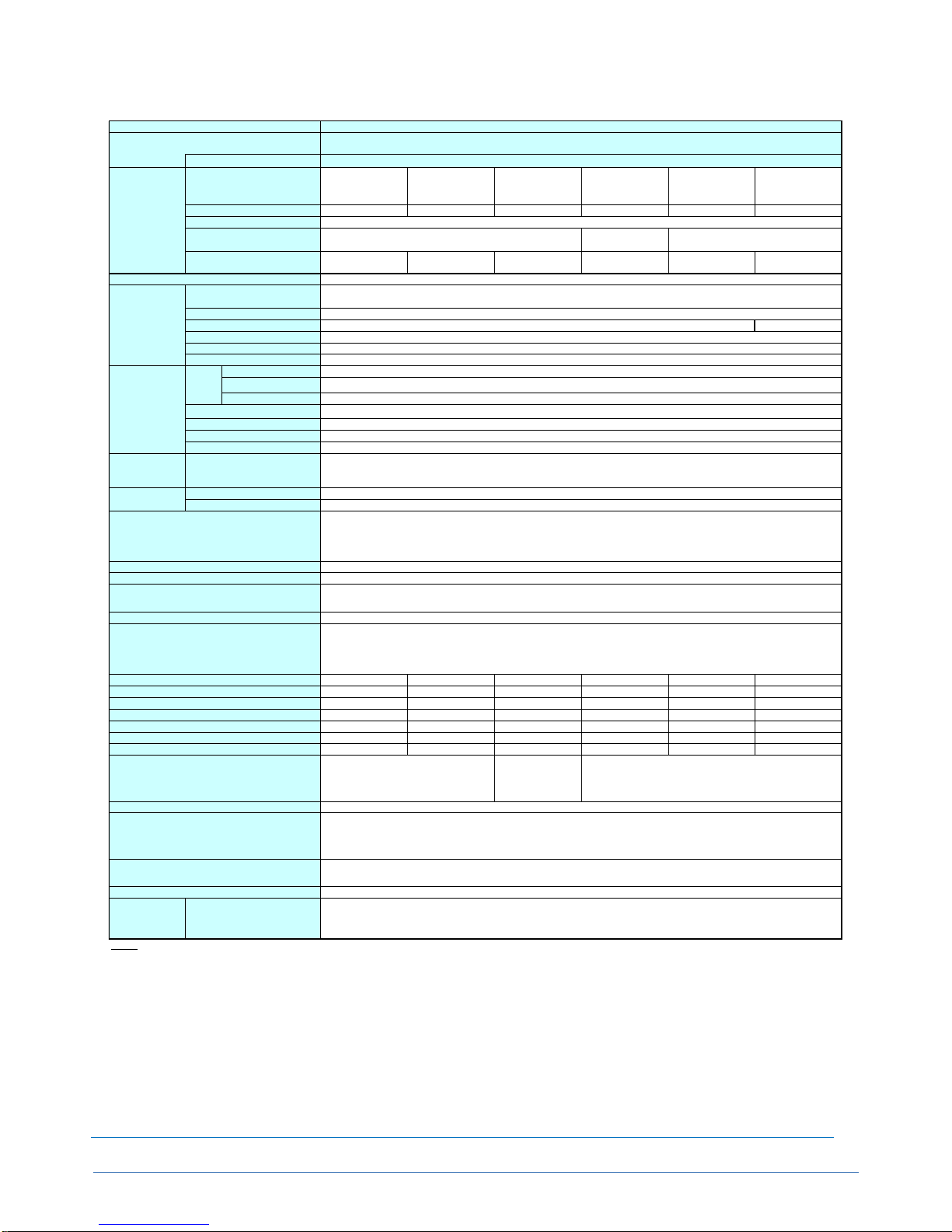
Technical Specification
NEC Express5800/A2040e (including COPT supported model)
Key Features
4U/up to 4way server with high performance with the latest Intel® Xeon® Scalable Processor Family
Up to 6TB of memory capacity, supporting high speed and energy efficient DDR4 memory
Redundant resources; clock, service processors (optional), and core I/O components (optional)
Capacity Optimization (COPT) supported model separately available in line-up for CPU resource optimization
Up to 8 2.5-inch HDD/SSD
High energy efficiency with 80 PLUS® Platinum certified power supply unit
Express5800/A2040e
NE3400-301F
NE3400-302F
Intel® Xeon®
Processor
Platinum 8180M
Intel® Xeon®
Processor
Platinum 8180
Intel® Xeon®
Processor
Platinum 8176M
Intel® Xeon®
Processor
Platinum 8176
Intel® Xeon®
Processor
Platinum 8160
2.50GHz 2.10GHz 2.10GHz
2/4
38.5MB 33MB
28C/56T 24C / 48T
Intel® C620 chipset
Not pre-installed
RDIMM : 1.5TB (48x 32GB), RDIMM-3DS : 6TB (48x 128GB)
DDR4-2666 RDIMM (8/16/32GB), DDR4-2666 RDIMM-3DS (64/128GB)
2666MHz
ECC, SDDC, ADDDC
Supported
Supported
-
2.5-inch HDD: SAS 9.6TB (8x 1.2TB), 2.-inch SSD: SAS 3.2TB (8x 400GB)
Supported
SAS 12Gb/s : RAID 0/1/5/6/10/50/60 (optional)
- *1--
Expansion Slots
8x PCI Express 3.0 (x16 lane, x16 socket) (Low profile, 167.65mm in length)
8x PCI Express 3.0 (x8 lane, x8 socket) (Low profile, 167.65mm in length)
Embedded in management controller chip / 8MB
16,770,000 colors: 640x480, 800x600, 1,024x768, 1,152x864, 1,280x1,024, 1,600x1,200
2x USB3.0 (1x front, 1x rear), 1x USB2.0 (1x internal)
1x SUV (rear) (2x USB2.0, 1x serial port (RS-232C/D-Sub 9pin),
1x Analog RGB (Mini D-Sub 15pin)
2x Management LAN connector (1000BASE-T/100BASE-TX/10BASE-T, RJ-45, 2x rear)
Supported (optional, hot-plug available)
Supported (standard, hot-plug available)
444.2mm × 742.3mm × 174.3mm (w/o front bezel/slide rail/protuberance)
482.6mm × 928.8mm × 175.8mm (including front bezel/slide rail/protuberance)
41.5kg / 57.4kg (including rail)
Not pre-installed
AC Power Unit
1000W/1600W 80 PLUS® Platinum, hot plug (max. 4 units)
AC100V/200V±10%, 50/60Hz±3Hz
863VA/846W 863VA/846W 863VA/846W 863VA/846W 863VA/846W
2827VA/2771W 2781VA/2725W 2655VA/2602W 2608VA/2556W 2543VA/2492W
2899VA/2841W 2853VA/2796W 2726VA/2672W 2680VA/2626W 2615VA/2563W
859VA/842W 859VA/842W 859VA/842W 859VA/842W 859VA/842W
2813VA/2757W 2767VA/2712W 2641VA/2589W 2595VA/2543W 2531VA/2480W
2885VA/2827W 2838VA/2782W 2713VA/2659W 2666VA/2613W 2602VA/2550W
10228KJ/h 10064KJ/h 9619KJ/h 9454KJ/h 9226KJ/h
Operating: 10 to 35℃,
Non-operating: -10 to 55℃
Operating: 10 to 40℃
Non-operating: -10 to 55℃
Operating: 20 to 80%, Non-operating: 20 to 80% (no condensation either operating or non-operating)
EXPRESSBUILDER(ESMPRO/ServerManager(Windows), ESMPRO/ServerAgentService,
Users Guide (including e-document), Start-up Guide, SUB Cable,
Rack Mount Kit, TeDoLi (diag. tool)
FCC, UL, CE, BSMI, RoHS, WEEE
-
Microsoft® Windows Server® 2016 Standard, Microsoft® Windows Server® 2016 Datacenter
Red Hat® Enterprise Linux 7.4
VMware® ESXi™ 6.5 Update 1
NOTE:
*1
*2
Available number of the Expansion Slot depends on the number of CPUs.
*3
Min. Configuraiton: (2x CPU, 2x DIMM, 1x RAID Controller, 1x 1600W PSU)
Product Code
Model Name
CPU
Processor
COPT Model
Intel® Smart Cache (Last Level
Cache)
Number of CPUs, min./max.
Clock Speed
Chipset
Number of Cores (C) / Thread (T)
per CPU
Memory Module
Capacity, standard/maximum
Error Check, Correction
Memory Mirroring
Maximum Clock Speed
Memory
Auxiliary Storage
Device
Disk
Drive
Internal (standard)
Rank Sparing
Hot Plug
Internal (maximum)
Optical Disk Drive
Interface / RAID Level
Expansion Bay
FDD
Graphics
Chip/Video RAM
Supported Slots (*2)
Graphic Display / Resolution
Redundant Power Supply
Standard Interface
External Dimensions (width x depth x height)
Redundant Fan
Power Consumption
Weight (min.*3 / max.)
(100V max. configuration , 25℃ High Load)
(100V max. configuration , 25℃ Standby)
(200V max. configuration , 25℃ Standby)
(100V max. configuration , Maximum)
Calorific Value (KJ/h)
(200V max. configuration , Maximum)
(200V max. configuration , 25℃ High Load)
Accessories
Environmental Requirements: Humidity
Environmental Requirements: Temperature
Supported OS
(NEC Support)
Installed OS
External DVD Dual Drive should be installed for maintenance and/or OS re-installation purpose.
Regulatory and Safety
Page 5
CONFIGURATION GUIDE – NEC Express5800/A2040e, A1040e
NEC Corporation Rev.1.0 – June 2018
5
Express5800/A2040e
NE3400-301F
NE3400-302F
Intel® Xeon®
Processor
Gold 6150
Intel® Xeon®
Processor
Gold 6136
Intel® Xeon®
Processor
Gold 6144
Intel® Xeon®
Processor
Gold 5115
Intel® Xeon®
Processor
Platinum 8156
Intel® Xeon®
Processor
Gold 5122
2.70GHz 3.00GHz 3.50GHz 2.40GHz 3.60GHz 3.60GHz
2/4
24.75MB 13.75MB 16,5MB
18C / 36T 12C / 24T 8C / 16T 10C / 20T 4C / 8T 4C / 8T
Intel® C620 chipset
Not pre-installed
RDIMM : 1.5TB (48x 32GB), RDIMM-3DS : 6TB (48x 128GB)
DDR4-2666 RDIMM (8/16/32GB), DDR4-2666 RDIMM-3DS (64/128GB)
2666MHz 2400MHz
ECC, SDDC, ADDDC
Supported
Supported
-
2.5-inch HDD: SAS 9.6TB (8x 1.2TB), 2.-inch SSD: SAS 3.2TB (8x 400GB)
Supported
SAS 12Gb/s : RAID 0/1/5/6/10/50/60 (optional)
- *1--
Expansion Slots
8x PCI Express 3.0 (x16 lane, x16 socket) (Low profile, 167.65mm in length)
8x PCI Express 3.0 (x8 lane, x8 socket) (Low profile, 167.65mm in length)
Embedded in management controller chip / 8MB
16,770,000 colors: 640x480, 800x600, 1,024x768, 1,152x864, 1,280x1,024, 1,600x1,200
2x USB3.0 (1x front, 1x rear), 1x USB2.0 (1x internal)
1x SUV (rear) (2x USB2.0, 1x serial port (RS-232C/D-Sub 9pin),
1x Analog RGB (Mini D-Sub 15pin)
2x Management LAN connector (1000BASE-T/100BASE-TX/10BASE-T, RJ-45, 2x rear)
Supported (optional, hot-plug available)
Supported (standard, hot-plug available)
444.2mm × 742.3mm × 174.3mm (w/o front bezel/slide rail/protuberance)
482.6mm × 928.8mm × 175.8mm (including front bezel/slide rail/protuberance)
444.2mm × 742.3mm × 174.3mm (w/o front bezel/slide rail/protuberance)
Not pre-installed
AC Power Unit
1000W/1600W 80 PLUS® Platinum, hot plug (max. 4 units)
AC100V/200V±10%, 50/60Hz±3Hz
863VA/846W 863VA/846W 863VA/846W 863VA/846W 863VA/846W 863VA/846W
2608VA/2556W 2543VA/2492W 2543VA/2492W 2263VA/2217W 2349VA/2302W 2349VA/2302W
2680VA/2626W 2615VA/2563W 2615VA/2563W 2334VA/2288W 2421VA/2372W 2421VA/2372W
859VA/842W 859VA/842W 859VA/842W 859VA/842W 859VA/842W 859VA/842W
2595VA/2543W 2531VA/2480W 2531VA/2480W 2251VA/2206W 2337VA/2290W 2337VA/2290W
2666VA/2613W 2602VA/2550W 2602VA/2550W 2323VA/2276W 2409VA/2360W 2409VA/2360W
9454KJ/h 9226KJ/h 9226KJ/h 8236KJ/h 8540KJ/h 8540KJ/h
Operating: 10 to 40℃
Non-operating: -10 to 55℃
Operating: 10 to
40℃
Non-operating: -10 to
55℃
Operating: 10 to 40℃
Non-operating: -10 to 55℃
Operating: 20 to 80%, Non-operating: 20 to 80% (no condensation either operating or non-operating)
EXPRESSBUILDER(ESMPRO/ServerManager(Windows), ESMPRO/ServerAgentService,
Users Guide (including e-document), Start-up Guide, SUB Cable,
Rack Mount Kit, TeDoLi (diag. tool)
FCC, UL, CE, BSMI, RoHS, WEEE
-
Microsoft® Windows Server® 2016 Standard, Microsoft® Windows Server® 2016 Datacenter
Red Hat® Enterprise Linux 7.4
VMware® ESXi™ 6.5 Update 1
NOTE:
*1
*2
Available number of the Expansion Slot depends on the number of CPUs.
*3
Min. Configuraiton: (2x CPU, 2x DIMM, 1x RAID Controller, 1x 1600W PSU)
External DVD Dual Drive should be installed for maintenance and/or OS re-installation purpose.
Product Code
Model Name
CPU
Processor
COPT Model
Intel® Smart Cache (Last Level
Cache)
Number of CPUs, min./max.
Clock Speed
Chipset
Number of Cores (C) / Thread (T)
per CPU
Memory Module
Memory
Capacity, standard/maximum
Error Check, Correction
Memory Mirroring
Maximum Clock Speed
Rank Sparing
Auxiliary Storage
Device
Disk
Drive
Internal (standard)
Hot Plug
Internal (maximum)
Optical Disk Drive
Interface / RAID Level
Expansion Bay
FDD
Graphics
Chip/Video RAM
Supported Slots (*2)
Graphic Display / Resolution
Redundant Power Supply
Standard Interface
External Dimensions (width x depth x height)
Redundant Fan
Power Consumption
Weight (min.*3 / max.)
(100V max. configuration , 25℃ High Load)
(100V max. configuration , 25℃ Standby)
(200V max. configuration , 25℃ Standby)
(100V max. configuration , Maximum)
Calorific Value (KJ/h)
(200V max. configuration , Maximum)
(200V max. configuration , 25℃ High Load)
Accessories
Environmental Requirements: Humidity
Environmental Requirements: Temperature
Supported OS
(NEC Support)
Installed OS
Regulatory and Safety
Page 6

CONFIGURATION GUIDE – NEC Express5800/A2040e, A1040e
NEC Corporation Rev.1.0 – June 2018
6
NEC Express5800/A1040e
Key Features
4U/up to 4way server with high performance with the latest Intel® Xeon® Scalable Processor Family
Up to 6TB of memory capacity, supporting high speed and energy efficient DDR4 memory
Up to 8 2.5-inch HDD/SSD
High energy efficiency with 80 PLUS® Platinum certified power supply unit
Express5800/A1040e
NE3300-301F
-
Intel® Xeon®
Processor
Platinum 8180M
Intel® Xeon®
Processor
Platinum 8180
Intel® Xeon®
Processor
Platinum 8176M
Intel® Xeon®
Processor
Platinum 8176
Intel® Xeon®
Processor
Platinum 8160
2.50GHz 2.10GHz 2.10GHz
1/4
38.5MB 33MB
28C/56T 24C / 48T
Intel® C620 chipset
Not pre-installed
RDIMM : 1.5TB (48x 32GB), RDIMM-3DS : 6TB (48x 128GB)
DDR4-2666 RDIMM (8/16/32GB), DDR4-2666 RDIMM-3DS (64/128GB)
2666MHz
ECC, SDDC, ADDDC
Supported
Supported
-
2.5-inch HDD: SAS 9.6TB (8x 1.2TB), 2.-inch SSD: SAS 3.2TB (8x 400GB)
Supported
SAS 12Gb/s : RAID 0/1/5/6/10/50/60 (optional)
- *1--
Expansion Slots
8x PCI Express 3.0 (x16 lane, x16 socket) (Low profile, 167.65mm in length)
5x PCI Express 3.0 (x8 lane, x8 socket) (Low profile, 167.65mm in length)
Embedded in management controller chip / 8MB
16,770,000 colors: 640x480, 800x600, 1,024x768, 1,152x864, 1,280x1,024, 1,600x1,200
2x USB3.0 (1x front, 1x rear), 1x USB2.0 (1x internal)
1x SUV (rear) (2x USB2.0, 1x serial port (RS-232C/D-Sub 9pin),
1x Analog RGB (Mini D-Sub 15pin)
1x Management LAN connector (1000BASE-T/100BASE-TX/10BASE-T, RJ-45, 2x rear)
Supported (optional, hot-plug available)
Supported (standard, hot-plug available)
444.2mm × 742.3mm × 174.3mm (w/o front bezel/slide rail/protuberance)
482.6mm × 928.8mm × 175.8mm (including front bezel/slide rail/protuberance)
39.9kg / 55.6kg (including rail)
Not pre-installed
AC Power Unit
1000W/1600W 80 PLUS® Platinum, hot plug (max. 4 units)
AC100V/200V±10%, 50/60Hz±3Hz
802VA/786W 802VA/786W 802VA/786W 802VA/786W 802VA/786W
2741VA/2686W 2695VA/2641W 2569VA/2517W 2522VA/2471W 2457VA/2408W
2813VA/2757W 2766VA/2711W 2640VA/2588W 2594VA/2542W 2529VA/2478W
798VA/782W 798VA/782W 798VA/782W 798VA/782W 798VA/782W
2728VA/2673W 2681VA/2628W 2556VA/2505W 2509VA/2459W 2445VA/2396W
2799VA/2743W 2753VA/2698W 2627VA/2575W 2581VA/2529W 2516VA/2466W
9924KJ/h 9760KJ/h 9315KJ/h 9151KJ/h 8922KJ/h
Operating: 10 to 35℃,
Non-operating: -10 to 55℃
Operating: 10 to 40℃
Non-operating: -10 to 55℃
Operating: 20 to 80%, Non-operating: 20 to 80% (no condensation either operating or non-operating)
EXPRESSBUILDER(ESMPRO/ServerManager(Windows), ESMPRO/ServerAgentService,
Users Guide (including e-document), Start-up Guide, SUB Cable,
Rack Mount Kit, TeDoLi (diag. tool)
FCC, UL, CE, BSMI, RoHS, WEEE
-
Microsoft® Windows Server® 2016 Standard, Microsoft® Windows Server® 2016 Datacenter
Red Hat® Enterprise Linux 7.4
VMware® ESXi™ 6.5 Update 1
NOTE:
*1
*2
Available number of the Expansion Slot depends on the number of CPUs.
*3 Min. Configuraiton: (1x CPU, 2x DIMM, 1x RAID Controller, 1x 1600W PSU)
Supported OS
(NEC Support)
Installed OS
Regulatory and Safety
Accessories
Environmental Requirements: Humidity
Environmental Requirements: Temperature
Calorific Value (KJ/h)
(200V max. configuration , Maximum)
(200V max. configuration , 25℃ High Load)
(200V max. configuration , 25℃ Standby)
(100V max. configuration , Maximum)
(100V max. configuration , 25℃ High Load)
(100V max. configuration , 25℃ Standby)
Power Consumption
Weight (min.*3 / max.)
External Dimensions (width x depth x height)
Redundant Fan
Redundant Power Supply
Standard Interface
Graphics
Chip/Video RAM
Supported Slots (*2)
Graphic Display / Resolution
Expansion Bay
FDD
Optical Disk Drive
Interface / RAID Level
Hot Plug
Internal (maximum)
Auxiliary Storage
Device
Disk
Drive
Internal (standard)
Memory
Capacity, standard/maximum
Error Check, Correction
Memory Mirroring
Maximum Clock Speed
Rank Sparing
Memory Module
Chipset
Number of Cores (C) / Thread (T)
per CPU
COPT Model
CPU
Processor
Intel® Smart Cache (Last Level
Cache)
Number of CPUs, min./max.
Clock Speed
External DVD Dual Drive should be installed for maintenance and/or OS re-installation purpose.
Product Code
Model Name
Page 7

CONFIGURATION GUIDE – NEC Express5800/A2040e, A1040e
NEC Corporation Rev.1.0 – June 2018
7
Express5800/A1040e
NE3300-301F
-
Intel® Xeon®
Processor
Gold 6150
Intel® Xeon®
Processor
Gold 6136
Intel® Xeon®
Processor
Gold 6144
Intel® Xeon®
Processor
Gold 5115
Intel® Xeon®
Processor
Platinum 8156
Intel® Xeon®
Processor
Gold 5122
2.70GHz 3.00GHz 3.50GHz 2.40GHz 3.60GHz 3.60GHz
1/4
24.75MB 13.75MB 16,5MB
18C / 36T 12C / 24T 8C / 16T 10C / 20T 4C / 8T 4C / 8T
Intel® C620 chipset
Not pre-installed
RDIMM : 1.5TB (48x 32GB), RDIMM-3DS : 6TB (48x 128GB)
DDR4-2666 RDIMM (8/16/32GB), DDR4-2666 RDIMM-3DS (64/128GB)
2666MHz 2400MHz
ECC, SDDC, ADDDC
Supported
Supported
-
2.5-inch HDD: SAS 9.6TB (8x 1.2TB), 2.-inch SSD: SAS 3.2TB (8x 400GB)
Supported
SAS 12Gb/s : RAID 0/1/5/6/10/50/60 (optional)
- *1--
Expansion Slots
8x PCI Express 3.0 (x16 lane, x16 socket) (Low profile, 167.65mm in length)
5x PCI Express 3.0 (x8 lane, x8 socket) (Low profile, 167.65mm in length)
Embedded in management controller chip / 8MB
16,770,000 colors: 640x480, 800x600, 1,024x768, 1,152x864, 1,280x1,024, 1,600x1,200
2x USB3.0 (1x front, 1x rear), 1x USB2.0 (1x internal)
1x SUV (rear) (2x USB2.0, 1x serial port (RS-232C/D-Sub 9pin),
1x Analog RGB (Mini D-Sub 15pin)
1x Management LAN connector (1000BASE-T/100BASE-TX/10BASE-T, RJ-45, 2x rear)
Supported (optional, hot-plug available)
Supported (standard, hot-plug available)
444.2mm × 742.3mm × 174.3mm (w/o front bezel/slide rail/protuberance)
482.6mm × 928.8mm × 175.8mm (including front bezel/slide rail/protuberance)
39.9kg / 55.6kg (including rail)
Not pre-installed
AC Power Unit
1000W/1600W 80 PLUS® Platinum, hot plug (max. 4 units)
AC100V/200V±10%, 50/60Hz±3Hz
802VA/786W 802VA/786W 802VA/786W 802VA/786W 802VA/786W 802VA/786W
2522VA/2471W 2457VA/2408W 2457VA/2408W 2176VA/2133W 2263VA/2218W 2263VA/2218W
2594VA/2542W 2529VA/2478W 2529VA/2478W 2248VA/2203W 2335VA/2288W 2335VA/2288W
798VA/782W 798VA/782W 798VA/782W 798VA/782W 798VA/782W 798VA/782W
2509VA/2459W 2445VA/2396W 2445VA/2396W 2166VA/2122W 2252VA/2206W 2252VA/2206W
2581VA/2529W 2516VA/2466W 2516VA/2466W 2237VA/2192W 2323VA/2276W 2323VA/2276W
9151KJ/h 8922KJ/h 8922KJ/h 7932KJ/h 8236KJ/h 8236KJ/h
Operating: 10 to 40℃
Non-operating: -10 to 55℃
Operating: 10 to
40℃
Non-operating: -10 to
55℃
Operating: 10 to 40℃
Non-operating: -10 to 55℃
Operating: 20 to 80%, Non-operating: 20 to 80% (no condensation either operating or non-operating)
EXPRESSBUILDER(ESMPRO/ServerManager(Windows), ESMPRO/ServerAgentService,
Users Guide (including e-document), Start-up Guide, SUB Cable,
Rack Mount Kit, TeDoLi (diag. tool)
FCC, UL, CE, BSMI, RoHS, WEEE
-
Microsoft® Windows Server® 2016 Standard, Microsoft® Windows Server® 2016 Datacenter
Red Hat® Enterprise Linux 7.4
VMware® ESXi™ 6.5 Update 1
NOTE:
*1
*2
Available number of the Expansion Slot depends on the number of CPUs.
*3 Min. Configuraiton: (1x CPU, 2x DIMM, 1x RAID Controller, 1x 1600W PSU)
External DVD Dual Drive should be installed for maintenance and/or OS re-installation purpose.
Model Name
Product Code
COPT Model
CPU
Processor
Number of CPUs, min./max.
Number of Cores (C) / Thread (T)
per CPU
Intel® Smart Cache (Last Level
Cache)
Clock Speed
Chipset
Memory Module
Maximum Clock Speed
Memory
Capacity, standard/maximum
Rank Sparing
Memory Mirroring
Internal (standard)
Interface / RAID Level
FDD
Error Check, Correction
Hot Plug
Internal (maximum)
Auxiliary Storage
Device
Disk
Drive
Optical Disk Drive
Expansion Bay
Supported Slots (*2)
Graphic Display / Resolution
Graphics
Chip/Video RAM
Standard Interface
Redundant Power Supply
Redundant Fan
External Dimensions (width x depth x height)
Weight (min.*3 / max.)
Power Consumption
(100V max. configuration , 25℃ Standby)
(100V max. configuration , 25℃ High Load)
(100V max. configuration , Maximum)
(200V max. configuration , 25℃ Standby)
Calorific Value (KJ/h)
(200V max. configuration , 25℃ High Load)
(200V max. configuration , Maximum)
Regulatory and Safety
Environmental Requirements: Temperature
Environmental Requirements: Humidity
Supported OS
(NEC Support)
Installed OS
Accessories
Page 8

CONFIGURATION GUIDE – NEC Express5800/A2040e, A1040e
NEC Corporation Rev.1.0 – June 2018
8
External Views
Front and Rear Views
Front View
Legend
A
SYSTEM POWER Switch
K
LAN POWER LED
(K1 only for A1040e)
B
UID (Unit ID) Switch
L
BMC Reset Switch
(L1 only for for A1040e)
C
Clear Switch
M
SYSTEM POWER LED
D
NMI Switch
N
UID (Unit ID) LED
E
BMC Ready LED
O
SYSTEM STATUS LED
F
BMC OFF Switch
P
USB Connector
G
Control Switch
Q
2.5-inch Hard Drive Bay
H
SYSTEM AC POWER LED
R
Auxiliary Cooling Fan Module (AFM)
I
Control LED
S
Slide Tag
J
LAN Connector (Maintenance LAN)
(J1 only for A1040e)
Page 9

CONFIGURATION GUIDE – NEC Express5800/A2040e, A1040e
NEC Corporation Rev.1.0 – June 2018
9
Rear View
Legend
A
LAN Connector (Management LAN)
(A1 only for A1040e)
E
PCI Card Expansion Slot 2
B
USB Connector
F
Power Supply Unit
C
SUV Cable Connector 1
G
IOB ALARM LED
D
UID (Unit ID) LED
H
Rear Connector Module (RCM)
1
2x USB Connectors and 1x Serial Port and 1x VGA Connector are available through SUV Cable
(attachement to the server, 2m length)
2
For A1040e, max. 13 slots
Page 10

CONFIGURATION GUIDE – NEC Express5800/A2040e, A1040e
NEC Corporation Rev.1.0 – June 2018
10
Dimensions (mm)
A2040e
A1040e
※ The above illustrations includes front bezel and slide rail (mount kit).
Page 11
CONFIGURATION GUIDE – NEC Express5800/A2040e, A1040e
NEC Corporation Rev.1.0 – June 2018
11
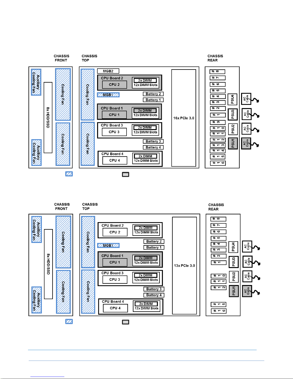
Configuration Diagram
A2040e
Legend: Standard components Minimum required components
A1040e
Legend: Standard components Minimum required components
Page 12

CONFIGURATION GUIDE – NEC Express5800/A2040e, A1040e
NEC Corporation Rev.1.0 – June 2018
12
Expansion Slot
Legend
A2040eA1040e
Slot #1
PCI Express 3.0 (x8 lane, x8 socket)
Slot #2
PCI Express 3.0 (x8 lane, x8 socket)
Slot #3
PCI Express 3.0 (x16 lane, x16 socket)
Slot #4
PCI Express 3.0 (x16 lane, x16 socket)
Slot #5
PCI Express 3.0 (x8 lane, x8 socket)
Slot #6
PCI Express 3.0 (x8 lane, x8 socket)
Slot #7
PCI Express 3.0 (x16 lane, x16 socket)
Slot #8
PCI Express 3.0 (x16 lane, x16 socket)
Slot #9
(A2040e only) PCI Express 3.0 (x8 lane, x8 socket)
Slot #10
PCI Express 3.0 (x8 lane, x8 socket)
Slot #11
PCI Express 3.0 (x16 lane, x16 socket)
Slot #12
PCI Express 3.0 (x16 lane, x16 socket)
Slot #13
(A2040e only) PCI Express 3.0 (x8 lane, x8 socket)
Slot #14
(A2040e only) PCI Express 3.0 (x8 lane, x8 socket)
Slot #15
PCI Express 3.0 (x16 lane, x16 socket)
Slot #16
PCI Express 3.0 (x16 lane, x16 socket)
NOTE:
For all PCI slots: Low Profile, 167.65mm in length
For A2040e: Slot#1 to #8 are available in case of 2CPU configuration, Slot#1 to #12 are available in case
of 3CPU configuration. All slots (Slot#1 to #16) are available in case of 4CPU configuration.
For A1040e: Slot#1 to #4 are available in case of 1CPU configuration, Slot#1 to #8 are available in case
of 2CPU configuration, Slot#10 to #12 are available in case of 3CPU configuration (Slot#9 is NOT
available), Slot#1 to #8, Slot#10 to # 11 and Slot#15 to 16 are available in case of 4CPU configuration
(Slot#9, #13 and #14 are NOT available)
Hot Plug supported: Slot #2 to #16 (15 slots) (not supported with A1040d)
Slot #1
Slot #
2
Slot #3 Slot #4 Slot #5 Slot #
6
Slot #
7
Slot #8 Slot #
9
Slot #1
0
Slot #
11
Slot #1
2
Slot #1
3
Slot #1
4
Slot #1
5
Slot #1
6
Page 13

CONFIGURATION GUIDE – NEC Express5800/A2040e, A1040e
NEC Corporation Rev.1.0 – June 2018
13
Server Configuration
1 Base Models
1.1 A2040e
Product Name/Description
Part Number
NEC Express5800/A2040e
No processor, no RAM, no HDD, no ODD, no Power Supply Unit, no OS
NE3400-301F
NEC Express5800/A2040e (COPT)
No processor, no RAM, no HDD, no ODD, no Power Supply Unit, no OS
NE3400-302F
NOTE:
The base models must be ordered with CPU Boards, Memory, Power Supply Units. Power cables should
be ordered as well for each geo.
Front Bezel and Cable Arm are not attached; need to be ordered separately if required.
Number of the available PCI Slots and Memory depends on the number of CPUs.
<Available PCI Slots and Maximum No. of Memory>
No. of
CPU
Max. No. of
DIMM
Available PCI Slots
#1
#2
#3
#4
#5
#6
#7
#8
#9
#10
#11
#12
#13
#14
#15
#16
2
24
Y Y Y Y Y Y Y
Y
‐
‐
‐ ‐ ‐ ‐ ‐ ‐ 3
36
Y Y Y Y Y Y Y Y Y Y Y
Y
‐
‐ ‐ ‐
4
48
Y Y Y Y Y Y Y Y Y Y Y Y Y Y Y
Y
1.2 A1040e
Product Name/Description
Part Number
NEC Express5800/A1040e
No processor, no RAM, no HDD, no ODD, no Power Supply Unit, no OS
NE3300-301F
NOTE:
The base models must be ordered with CPU Boards, Memory, Power Supply Units. Power cables should
be ordered as well for each geo.
Front Bezel and Cable Arm are not attached; need to be ordered separately if required.
Number of the available PCI Slots and Memory depends on the number of CPUs.
<Available PCI Slots and Maximum No. of Memory>
No. of
CPU
Max. No. of
DIMM
Available PCI Slots
#1
#2
#3
#4
#5
#6
#7
#8
#10
#11
#12
#15
#16
1
12
Y Y Y
Y
‐
‐ ‐ ‐
‐ ‐ ‐ ‐ ‐
2
24
Y Y Y Y Y Y Y Y ‐ ‐ ‐ ‐ ‐
3
36
Y Y Y Y Y Y Y Y Y Y Y ‐ ‐
4
48
Y Y Y Y Y Y Y Y Y Y Y Y Y
Page 14

CONFIGURATION GUIDE – NEC Express5800/A2040e, A1040e
NEC Corporation Rev.1.0 – June 2018
14
1.3 COPT
Capacity Optimization (COPT) is a function to optimize computing resources by enabling CPU cores as many
required per workload without any impact to the number of DIMM and PCI slots which depends on CPU
configuration.
When necessary, CPU core can be enabled additionally on-site.
COPT is available only with A2040d COPT supported model (NEC Express5800/A2040d (COPT)).
In order to enable CPU core, Core Activation Key should be ordered for the required number of cores.
Product Name/Description
Part Number
One Core Activation Key (for Embedded)
Need to order at the same time of ordering the server. As many CPU cores as
the ordered number of the One Core Activation Key (for Embedded) are to be
enabled when the ordered server is shipped.
Up to the ordered number of the One Core Activation Key (for Embedded),
CPU cores are available for use.
NE3401-H101F
One Core Activation Key (for Add-on)
The CPU core can be additionally enabled on-site by ordering the One Core
Activation Key (for Add-on).
As many Code Words as the ordered number of the One Core Activation Key
(for Add-on) are shipped, and additional CPU core can be enabled by applying
the Code Word to the server.
NE3401-H102F
NOTE:
Contact to our sales representative for software supporting COPT function.
When enabling CPU core (or socket) by Core Activation Key, please purchase required software license
as appropriate
In case of using socket license based software, please enable CPU core at the CPU socket on which the
software is operating. Software license is required for the socket with at least one enabled CPU core
Depending on the OS, the server may need to be rebooted to enable CPU cores.
Remarks to use COPT under Linux environment:
- When using Fibre Channel Controller (16Gbps) [NE3390-157A/158A], need to enable enough
number of CPU cores to have 4 or more logical processors,
Remarks to use COPT under Windows environment
- Depending on the number of enabled CPU cores, PCI card to be installed is limited. Please refer for
the details to “Installation Limitations for Windows”.
Remarks to use COPT under VMware environment:
- Need to purchase at least the same number of One Core Activation Key as the number of CPU
socket.
- Need to enable the same number of CPU cores among all CPUs (excluding CPUs with all cores
disabled)
<Examples of OK or NOT-OK configuration in case of 4CPU configuration>
Ex.1: OK
Ex.2: OK
Ex.3: NOT-OK
Ex.4: NOT-OK
CPU1: 1 core enabled
CPU1: 4 core enabled
CPU1: 1 core enabled
CPU1: 2 core enabled
CPU2: 1 core enabled
CPU2: 0 core enabled
CPU2: 1 core enabled
CPU2: 1 core enabled
CPU3: 1 core enabled
CPU3: 0 core enabled
CPU3: 1 core enabled
CPU3: 1 core enabled
CPU4: 1 core enabled
CPU4: 0 core enabled
CPU4: 0 core enabled
CPU4: 0 core enabled
For the details, please refer to the latest version of “Express5800/A2040e Capacity Optimization (COPT)
User's Guide”
Default setting of Core Optimization Mode is “Decentralize”, where the enabled CPU cores are distributed
to each socket equally.
Page 15

CONFIGURATION GUIDE – NEC Express5800/A2040e, A1040e
NEC Corporation Rev.1.0 – June 2018
15
2 CPU
A2040e (min. 2CPU / max. 4CPU)/ A1040e (min. 1CPU / max. 4CPU)
Product Name/Description
Part Number
CPU Board for Slot #1 and #2 (for 1st and 2nd processor)
CPU Board (28C/Platinum 8180M) Slot1/2 (*CTO*)
1 x Intel® Xeon® Processor Platinum 8180M (2.50 GHz, 28C/56T, 38.50MB, TDP
205W), 1.5TB/CPU
NOTE:
This is CTO categorized item; lead time for delivery is longer than other regular items.
NE3301-H101F
CPU Board (28C/Platinum 8180) Slot1/2
1 x Intel® Xeon® Processor Platinum 8180 (2.50 GHz, 28C/56T, 38.50MB, TDP 205W)
NE3301-H102F
CPU Board (28C/Platinum 8176M) Slot1/2 (*CTO*)
1 x Intel® Xeon® Processor Platinum 8176M (2.10 GHz, 28C/56T, 38.50MB, TDP
165W), 1.5TB/CPU
NOTE:
This is CTO categorized item; lead time for delivery is longer than other regular items.
NE3301-H103F
CPU Board (28C/Platinum 8176) Slot1/ 2
1 x Intel® Xeon® Processor Platinum 8176 (2.10 GHz, 28C/56T, 38.50MB, TDP 165W)
NE3301-H104F
CPU Board (24C/Platinum 8160) Slot1/2
1 x Intel® Xeon® Processor Platinum 8160 (2.10 GHz, 24C/48T, 33MB, TDP 150W)
NE3301-H105F
CPU Board (18C/Gold 6150) Slot1/2
1 x Intel® Xeon® Processor Gold 6150 (2.70 GHz, 18C/36T, 24.75MB, TDP 165W)
NE3301-H106F
CPU Board (12C/Gold 6136) Slot1/ 2
1 x Intel® Xeon® Processor Gold 6136 (3.00 GHz, 12C/24T, 24.75MB, TDP 150W)
NE3301-H107F
CPU Board (8C/Gold 6144) Slot1/2
1 x Intel® Xeon® Processor Gold 6144 (3.50 GHz, 8C/16T, 24.75MB, TDP 150W)
NE3301-H108F
CPU Board (10C/Gold 5115) Slot1/2
1 x Intel® Xeon® Processor Gold 5115 (2.40 GHz, 10C/20T, 13.75MB, TDP 85W)
NE3301-H109F
CPU Board (4C/Platinum 8156) Slot1/2
1 x Intel® Xeon® Processor Platinum 8156 (3.60 GHz, 4C/8T, 16.50MB, TDP 105W)
NE3301-H110F
CPU Board (4C/Gold 5122) Slot1/2
1 x Intel® Xeon® Processor Gold 5122 (3.60 GHz, 4C/8T, 16.50MB, TDP 105W)
NE3301-H111F
CPU Board for Slot #3 and #4 (for 3rd and 4th processor)
CPU Board (28C/Platinum 8180M) Slot3/4 (*CTO*)
1 x Intel® Xeon® Processor Platinum 8180M (2.50 GHz, 28C/56T, 38.50MB, TDP
205W), 1.5TB/CPU
NOTE:
This is CTO categorized item; lead time for delivery is longer than other regular items.
NE3301-H121F
CPU Board (28C/Platinum 8180) Slot3/4
1 x Intel® Xeon® Processor Platinum 8180 (2.50 GHz, 28C/56T, 38.50MB, TDP 205W)
NE3301-H122F
CPU Board (28C/Platinum 8176M) Slot3/4 (*CTO*)
1 x Intel® Xeon® Processor Platinum 8176M (2.10 GHz, 28C/56T, 38.50MB, TDP
165W), 1.5TB/CPU
NOTE:
This is CTO categorized item; lead time for delivery is longer than other regular items.
NE3301-H123F
CPU Board (28C/Platinum 8176) Slot3/4
1 x Intel® Xeon® Processor Platinum 8176 (2.10 GHz, 28C/56T, 38.50MB, TDP 165W)
NE3301-H124F
CPU Board (24C/Platinum 8160) Slot3/4
1 x Intel® Xeon® Processor Platinum 8160 (2.10 GHz, 24C/48T, 33MB, TDP 150W)
NE3301-H125F
CPU Board (18C/Gold 6150) Slot3/4
1 x Intel® Xeon® Processor Gold 6150 (2.70 GHz, 18C/36T, 24.75MB, TDP 165W)
NE3301-H126F
CPU Board (12C/Gold 6136) Slot3/4
1 x Intel® Xeon® Processor Gold 6136 (3.00 GHz, 12C/24T, 24.75MB, TDP 150W)
NE3301-H127F
CPU Board (8C/Gold 6144) Slot3/4
1 x Intel® Xeon® Processor Gold 6144 (3.50 GHz, 8C/16T, 24.75MB, TDP 150W)
NE3301-H128F
CPU Board (10C/Gold 5115) Slot3/4
1 x Intel® Xeon® Processor Gold 5115 (2.40 GHz, 10C/20T, 13.75MB, TDP 85W)
NE3301-H129F
CPU Board (4C/Platinum 8156) Slot3/4
NE3301-H130F
Page 16

CONFIGURATION GUIDE – NEC Express5800/A2040e, A1040e
NEC Corporation Rev.1.0 – June 2018
16
1 x Intel® Xeon® Processor Platinum 8156 (3.60 GHz, 4C/8T, 16.50MB, TDP 105W)
CPU Board (4C/Gold 5122) Slot3/4
1 x Intel® Xeon® Processor Gold 5122 (3.60 GHz, 4C/8T, 16.50MB, TDP 105W)
NE3301-H131F
NOTE:
For Slot #1 and #2, CPU Boards for Slot 1/2 should be installed, while for Slot #3 and #4, CPU Boards
for Slot 3/4 should be installed. CPU Boards with different CPU SKU cannot be mixed in a server.
Having CPUs with TDP 205W (Platinum 8180M/8180) or 150W (Gold 6144) in an environment of more
than 25℃ intake air temperature may cause larger noise than usual, depending on the status of server
operation.
CPU Functions
Intel® Xeon® Processors for this server supports the following CPU functions
Category
Function Name/Summary
64 bit
Intel® 64
64 bit function
Power Saving
Enhanced Intel SpeedStep® Technology
(Intel® Demand Bases Switching Technology)
Technology to decrease power consumption by adjusting voltage/clock per CPU workload
Power Saving
Intel® SpeedShift Technology
Technology to decrease power consumption by adjusting CPU clock
Performance
Intel® Turbo Boost Technology
Technology to boost clock frequency
Performance
Intel® Hyper-Threading Technology
Technology to use one core as two threads
Virtualization
Intel® Virtualization Technology
Technology to provide hardware (CPU) support for processor virtualization
Security
Execute Disable
Technology to avoid the execution of malware utilizing buffer over flow error
The maximum number of logical processors supported by OS
See the table below for the maximum number of logical processors that you can actually use on your system
Maximum Number of Logical Processors Supported by
Operating Systems
Maximum Number of Logical
Processors Supported by this
Server
Microsoft Windows Server 2016 Standard
Microsoft Windows Server 2016 Datacenter
640 1
224
Red Hat Enterprise Linux 7.4
576
224
Oracle Linux 7.3 (x86_64) UEK R4
2048
224
VMware ESXi 6.5 Update 1
576
224
1
The maximum number of logical processors when using Hyper-V are below:
Windows Server 2016 : 512
Page 17

CONFIGURATION GUIDE – NEC Express5800/A2040e, A1040e
NEC Corporation Rev.1.0 – June 2018
17
3 Memory
3.1 Memory Configuration
In addition to the standard features, 2 additional features are available; “Memory Rank Sparing” and “Memory
Mirroring”. Please go to the appropriate section in accordance with your memory configuration.
Memory Configuration Feature Comparison
standard
Memory Rank Sparing
Memory Mirroring
Summary
In case of correctable
errors, switching to
spare memory rank
Redundant memory
having the same data
Available Memory
-
1/2(8GB RDIMM),
1/2(16GB RDIMM)
3/4,1/2(32GB RDIMM)
7/8,3/4,5/8,1/2
(64GB RDIMM-3DS)
of physical memory。
1/2 of physical memory
Available Memory
Channel 1
6 6 6
Maximum Memory
Capacity
2
384GB(8GB RDIMM)
768GB(16GB RDIMM)
1536GB(32GB RDIMM)
3072GB(64GB RDIMM-
3DS)
192GB(8GB RDIMM)
384GB(16GB RDIMM)
1152GB,768GB
(32GB RDIMM)
2688GB,2304GB,1920GB
1536GB(64GB RDIMM-3DS)
192GB(8GB RDIMM)
384GB(16GB RDIMM)
768GB(32GB RDIMM)
Data Correction
ECC, SDDC, ADDDC
←
←
Notes
RDIMM and LRDIMM
cannot be mixed
Need to order memory for
sparing
Need to order memory
for mirroring
1
6 memory channels per CPU
2
All DIMMs have the same capacity
Customized Configuration Service (at the Server Delivery)
Product Name/Description
Part Number
Customized Service: Distribution Mode for COPT
NE3300-SV801
NOTE:
This is the service product for A2040e COPT Model. With this service product, the location of installing
Memory can be changed as required from the location defined by the standard BTO Configuration.
Up to one item (service) can be ordered per one server.
When allocating enabled CPU cores to all CPU (distributed), this service is recommended to use so that
Memory can be distributed, too. Please refer to “Memory” of “Reference” section for the details.
Page 18

CONFIGURATION GUIDE – NEC Express5800/A2040e, A1040e
NEC Corporation Rev.1.0 – June 2018
18
3.1.1 Memory (standard)
Max. 6 sets (12x DIMMs) per CPU Board
Category
Product Name/Description
Part Number
Registered DIMM
(RDIMM)
16GB MEM (2x8GB/R/SR)
2x 8GB Registered DIMM, DDR4-2666(PC4-2666), ECC
NOTE:
- To be released in Sep./2018
NE3302-H101F
32GB MEM (2x16GB/R/SR)
2x 16GB Registered DIMM, DDR4-2666(PC4-2666), ECC
NE3302-H102F
64GB MEM (2x32GB/R/DR)
2x 32GB Registered DIMM, DDR4-2666(PC4-2666), ECC
NE3302-H103F
Registered DIMM
3DS
(RDIMM-3DS)
128GB MEM (2x64GB/R-3DS/QR) (*CTO*)
2x 64GB Registered DIMM 3DS, DDR4-2666(PC4-2666),
ECC
NOTE:
- This is CTO categorized item; lead time for delivery is
longer than other regular items.
NE3302-H104F
256GB MEM (2x128GB/R-3DS/8R) (*CTO*)
2x 128GB Registered DIMM 3DS, DDR4-2666(PC4-2666),
ECC
NOTE:
- To be released in Sep./2018
- This is CTO categorized item; lead time for delivery is
longer than other regular items.
- In case of installing 12 of this product (24 x DIMM),
Platinum 8180M or 8176M processors are required.
NE3302-H105F
NOTE:
Not-preinstalled. Need to order at least 1 set (2x DIMM)
5 sets (10x DIMM) per CPU Board is not allowed to configure, in order to avoid performance decrease
risk due to unbalanced memory.
RDIMM and RDIMM-3DS cannot be mixed in a server
Page 19

CONFIGURATION GUIDE – NEC Express5800/A2040e, A1040e
NEC Corporation Rev.1.0 – June 2018
19
3.1.2 Memory Rank Sparing
Max. 3 sets (12x DIMMs) per CPU Board
Product Name/Description
Part Number
32GB MEM for Memory Rank Sparing (4x8GB/R/SR)
4x 8GB Registered DIMM, DDR4-2666(PC4-2666), ECC
NOTE:
To be released in Sep./2018
NE3302-H111F
64GBMEM for Memory Rank Sparing (4x16GB/R/SR)
4x 16GB Registered DIMM, DDR4-2666(PC4-2666), ECC
NE3302-H112F
128GB MEM for Memory Rank Sparing (4x32GB/R/DR)
4x 32GB Registered DIMM, DDR4-2666(PC4-2666), ECC
NE3302-H113F
256GB MEM for Memory Rank Sparing (4x64GB/R-3DS/QR)
4x 64GB Registered DIMM 3DS, DDR4-2666(PC4-2666), ECC
NE3302-H114F
NOTE:
Not-preinstalled. Need to order at least 1 set (4x DIMM)
Different Memory cannot be mixed in a server.
1 spare rank available with 8GB/16GB RDIMM, 1 or 2 spare ranks available with 32GB RDIMM, 1, 2, 3
or 4 spare ranks available with 64GB RDIMM-3DS.
Logical Memory Capacity at Memory Rank Sparing
The following table shows logical memory capacity at memory rank sparing, showing the capacity per CPU.
No. of DIMM
Physical Memory Capacity
8GB RDIMM
16GB RDIMM
32GB RDIMM
1 Spare Rank
1 Spare Rank
1 Spare Rank
2 Spare Ranks
4
(not available)
(not available)
96GB
64GB
8
32GB
64GB
192GB
128GB
12
48GB
96GB
288GB
192GB
16
64GB
128GB
384GB
256GB
20
80GB
160GB
480GB
320GB
24
96GB
192GB
576GB
384GB
28
112GB
224GB
672GB
448GB
32
128GB
256GB
768GB
512GB
36
144GB
288GB
864GB
576GB
40
160GB
320GB
960GB
640GB
44
176GB
352GB
1056GB
704GB
48
192GB
384GB
1152GB
768GB
Page 20

CONFIGURATION GUIDE – NEC Express5800/A2040e, A1040e
NEC Corporation Rev.1.0 – June 2018
20
3.1.3 Memory Mirroring
Max. 4 sets (12x DIMMs) per CPU Board
Product Name/Description
Part Number
24GB MEM for Mirroring (3x8GB/R/SR)
3x 8GB Registered DIMM, DDR4-2666(PC4-2666), ECC
NOTE:
To be released in Sep./2018
NE3302-H121F
48GB MEM for Mirroring (3x16GB/R/SR)
3x 16GB Registered DIMM, DDR4-2666(PC4-2666), ECC
NE3302-H122F
96GB MEM for Mirroring (3x32GB/R/DR)
3x 32GB Registered DIMM, DDR4-2666(PC4-2666), ECC
NE3302-H123F
NOTE:
Not-preinstalled. Need to order at least 1 set (4x DIMM)
Different Memory cannot be mixed in a server.
Memory Clock
DDR4 Memory clock is defferent depending on CPU. Please refer to the below for the maximum clock.
Please refer to “Memory” of “Reference” section for the details, too.
CPU
Memory
No. of DIMM
per CPU
Memory Clock
(1.2V)
Xeon®
Platinum 8180M
Platinum 8180
Platinum 8176M
Platinum 8176
Platinum 8160
Platinum 8156
Gold 6150
Gold 6136
Gold 6144
Gold 5115
RDIMM(8,16,32GB)
Up to 12
2666 MHz
RDIMM-3DS (64, 128GB)
Up to 12
2666 MHz
Xeon®
Gold 5122
RDIMM(8,16,32GB)
Up to 12
2400 MHz
RDIMM-3DS (64, 128GB)
Up to 12
2400 MHz
Maximum Memory Capacity
The available memory capacity is different depending on the OS, as the following list shows:
Maximum Memory Capacity supported by each OS
Max. Memory Capacity for
this Server
Microsoft Windows Server 2016 Standard 1
Microsoft Windows Server 2016 Datacenter 1
24 TB
6TB
Red Hat Enterprise Linux 7.4
12 TB
3 TB
Oracle Linux 7.4 (x86_64) UEK R4
64 TB
2 TB
VMware ESXi 6.5 Update 1 2
12TB
6 TB 2
1
The Maximum Memory Capacity in using Hyper-V:
Windows Server 2016: 24TB
Page 21

CONFIGURATION GUIDE – NEC Express5800/A2040e, A1040e
NEC Corporation Rev.1.0 – June 2018
21
2
The Maximum Memory Capacity for virtual machine: 6TB
4 Internal Disk Drives
4.1 RAID Configuration
RAID0/1/5/6/10/50/60 is supported.
2 kinds of RAID Controller are supported; with 1GB or 2GB cache. Up to 8 internal drives can be connected.
Controller
RAID
No. of Disk
Capacity
Hot Spare
NE3303-178
or
NE3303-177
RAID 0 (striping)
1 ~ 8
Drive Capacity x No. of Drive
N
RAID 1 (mirroring)
2
Drive Capacity x No. of Drive / 2
Y
RAID 5 (parity)
3 ~ 8
Drive Capacity x (No. of Drive-1)
Y
RAID 6 (double parity)
3 ~ 8
Drive Capacity x (No. of Drive-2)
Y
RAID 10 (RAID1 + RAID0)
4 / 6 / 8
Drive Capacity x No. of Drive / 2
Y
RAID 50 (RAID5 + RAID0)
6 / 8
Drive Capacity x (No. of Drive-2)
Y
RAID 60 (RAID6 + RAID0)
6 / 8
Drive Capacity x (No. of Drive-4)
Y
NOTE:
Needs to order RAID Controller to configure internal drives
For RAID Configuration, same type of internal drives need to be ordered within one RAID group (pack)
Multiple RAID group can be configured by one RAID Controller. In case of RAID1, 4 groups at maximum.
Different capacity/rotation speed/disk type of internal drives can be mixed among different RAID groups.
When configuring hot-spare disks, need to use same type of internal disk for the RAID group.
- All internal drives are same type, Global Hot Spare can be available.
- When mixing different capacity/rotation speed/disk type drives, need to use Dedicated Hot Spare
per RAID group.
Please refer to “Internal Drive” of “Reference” section for the details about Internal Drive: Priority/Order of
Installation.
Page 22

CONFIGURATION GUIDE – NEC Express5800/A2040e, A1040e
NEC Corporation Rev.1.0 – June 2018
22
4.2 Internal Drive Configuration
For RAID Configuration, same type of internal drives need to be ordered within one RAID group (pack)
With 1 RAID Controller configuration, different HDDs, SDDs or HDD and SSD cannot be configured in the
BTO. When mixing these drives, please refer to the section “Internal Disk” at “References”.
RAID 0/1/5/6/10 can be configured at BTO Configuration. For RAID 50/60, need to configure after the
delivery.
The delivery lead time of SSD is longer than the others. Please contact to our sales representative for the
delivery.
4.2.1 RAID Controller (2GB Cache/Flash) Configuration
Category
Product Name/Description
Part Number
Controller
(Need to order 1)
RAID Controller (2GB, RAID 0/1/5/6)
LSI MegaRAID SAS 9362-8i
RAID0/1/5/6/10/50/60, 2GB Cache, Internal 8 port (4x
2connectors), PCIe 3.0(x8), SAS 12Gb/s
NE3303-178
Flash Back-up
(optional)
Flash Back-up Unit
LSI MegaRAID SAS 9362-8i
300mm Flash Back-up Unit Cable attached
NE3303-H101
Cable
SAS Cable
1 x mini-SAS to 1 x mini-SAS, x2
(included)
HDD Cage
2.5-inch HDD Cage
8x 2.5-inch, Drive Bay, Hot-Plug supported
(included)
Internal
Drives
(Max. 8)
SAS
HDD
300GB HDD
1x 300 GB SAS HDD, 2.5-inch, 12Gb/s, 10,000 rpm,
512B sector
NE3350-479A
600GB HDD
1x 600 GB SAS HDD, 2.5-inch, 12Gb/s, 10,000 rpm,
512B sector
NE3350-481A
900GB HDD
1x 900 GB SAS HDD, 2.5-inch, 12Gb/s, 10,000 rpm,
512B sector
NE3350-482A
1.2TB HDD
1x1.2TB SAS HDD, 2.5-inch, 12Gb/s, 10,000 rpm,
512B sector
NE3350-483A
300GB HDD
1x 300 GB SAS HDD, 2.5-inch, 12Gb/s, 15,000 rpm,
512B sector
NE3350-485A
600GB HDD
1x 600 GB SAS HDD, 2.5-inch, 12Gb/s, 15,000 rpm,
512B sector
NE3350-518A
SAS
SSD
(eMLC)
400GB SSD
1x 400 GB SAS SSD, eMLC, 2.5-inch, 12Gb/s,
512B sector
NOTE:
This is CTO categorized item; lead time for delivery is longer
(around 2 months).
NE3350-722A
NOTE:
Need to order at least 1 internal drive, when RAID controller included.
Page 23

CONFIGURATION GUIDE – NEC Express5800/A2040e, A1040e
NEC Corporation Rev.1.0 – June 2018
23
4.2.2 RAID Controller (1GB Cache/Flash) Configuration
Category
Product Name/Description
Part Number
Controller
(Need to order 1)
RAID Contoroller (1GB, RAID 0/1/5/6)
LSI MegaRAID SAS 9362-8i
RAID0/1/5/6/10/50/60, 1GB Cache, Internal 8 port (4x
2connectors), PCIe 3.0(x8), SAS 12Gb/s
NE3303-177
Flash Back-up
(optional)
Flash Back-up Unit
LSI MegaRAID SAS 9362-8i
300mm Flash Back-up Unit Cable attached
NE3303-H101
Cable
SAS Cable
1 x mini-SAS to 1 x mini-SAS, x2
(included)
HDD Cage
2.5-inch HDD Cage
8x 2.5-inch, Drive Bay, Hot-Plug supported
(included)
Internal
Drives
(Max. 8)
SAS
HDD
300GB HDD
1x 300 GB SAS HDD, 2.5-inch, 12Gb/s, 10,000 rpm,
512B sector
NE3350-479A
600GB HDD
1x 600 GB SAS HDD, 2.5-inch, 12Gb/s, 10,000 rpm,
512B sector
NE3350-481A
900GB HDD
1x 900 GB SAS HDD, 2.5-inch, 12Gb/s, 10,000 rpm,
512B sector
NE3350-482A
1.2TB HDD
1x1.2TB SAS HDD, 2.5-inch, 12Gb/s, 10,000 rpm,
512B sector
NE3350-483A
300GB HDD
1x 300 GB SAS HDD, 2.5-inch, 12Gb/s, 15,000 rpm,
512B sector
NE3350-485A
600GB HDD
1x 600 GB SAS HDD, 2.5-inch, 12Gb/s, 15,000 rpm,
512B sector
NE3350-518A
SAS
SSD
(eMLC)
400GB SSD
1x 400 GB SAS SSD, eMLC, 2.5-inch, 12Gb/s,
512B sector
NOTE:
This is CTO categorized item; lead time for delivery is longer
(around 2 months).
NE3350-722A
NOTE:
Need to order at least 1 internal drive, when RAID controller included.
Page 24

CONFIGURATION GUIDE – NEC Express5800/A2040e, A1040e
NEC Corporation Rev.1.0 – June 2018
24
5 Optical Drive
Up to 1 Optical Drive (external) can be connected
Category
Product Name/Description
Part Number
External
External DVD Dual Drive
Slim DVD Dual drive, USB bus powered, not including writing software,
Cable length: 60cm
DVD read speed: 8x (DVD-ROM/-R/-RW/-R DL/+R/+RW/+R DL)
CD read speed: 24x (CD-ROM/-R/-RW)
N8160-101F
NOTE:
Internal DVD Drive cannot be mounted.
Cannot be connected to the USB port of SUV cable.
6 PCI Card
Please refer to “Available Slots” of “References” section regarding PCI Slots; Available Slots and Installation
Limitations.
6.1 PCI Hot Plug Kit
This Kit is required for PCI Card hot plug (replace/add) for A2040e.
Product Name/Description
Part Number
PCI Hot Plug Kit
NE3415-H102
NOTE:
A1040e does not support PCI Hot Plug.
6.2 Network Interface Controller
Category
Product Name/Description
Part Number
1GbE
1000 BASE-T Adapter (2ch)
Broadcom BCM5718
PCIe 2.0(x4) (Performance: PCIe 2.0(x1))
Low Profile
NOTE:
PXE Boot by IPv6 not supported
NE3304-151M
1000 BASE-TAdapter (4ch)
Broadcom BCM5719
PCIe 2.0(x4), Low Profile
NOTE:
- Network cables with RJ-45 plug covers cannot be used.
- PXE Boot by IPv6 not supported
NE3304-152M
10GbE
10G BASE Adapter (SFP+/2ch)
Intel Ethernet Converged Network Adapters X710
PCIe 3.0(x8)
NOTE:
- When connecting to the optical fibre cable, NE3304-129 (SFP+
Module (10G-SR)) needs to be ordered per one port (max. 2)
- Connection with Twinax cable is available. Please refer to the
Users guide for the validated cable
NE3304-158
Page 25

CONFIGURATION GUIDE – NEC Express5800/A2040e, A1040e
NEC Corporation Rev.1.0 – June 2018
25
10G BASE Adapter (QSFP+/4ch)
Intel Ethernet Converged Network Adapters XL710
PCIe 3.0(x8), Low Profile
Supported OS: RHEL7.4 and ESXi6.5u1 only
NOTE:
- Not supported for 40Gb connection
- When connecting to the optical fibre cable, NE3304-161
(QSFP+ Module (10G-SR)) needs to be ordered (max. 1 per
port).
- Connection via Twinax cable is availalbe. Please refer to the
technical guide for LAN boards for the verified cables.
- Connection via optical fiber and Twinax cable is only supported
for breakout cable.
NE3304-159
10G BASE-T Adapter (2ch)
Intel Ethernet Controller X550
PCIe 3.0(x4), Low Profile
NE3304-157
Module
SFP+ Module (10G-SR)
1 x SFP+ Module for NE3304-149
NOTE:
This item is not built-in configured at the delivery (shipped
separtely)
NE3304-129
QSFP+ Module
1 x QSFP+ Module for NE3304-159
NOTE:
This item is not built-in configured at the delivery (shipped
separtely)
NE3304-161
NOTE:
Network Interface Controller not pre-installed and this server does not have LAN interface/port at the base
module. Needs to order at least 1 card.
PXE (Preboot eXecution Environment) boot is supported by
- 1000BASE-T Adapter (2ch) (NE3304-151M)
- 1000BASE-T Adapter (4ch) (NE3304-152M)
- 10GBASE Adapter (SFP+/2ch) (NE3304-158),
- 10G BASE Adapter (QSFP+/4ch) (NE3304-159)
- 10GBASE-T Adapter (2ch) (NE3304-157.
WOL (Wake On LAN) is supported by 1000BASE-T Adapter (2ch) (NE3304-151M) only.
When booting OS by PXE boot, please select IPv4 for network settings.
For A2040e, Network Interface Controller supports Hot Plug. In order to enable Hot Plug, NE3415-H102
PCI Hot Plug Kit is required.
Page 26

CONFIGURATION GUIDE – NEC Express5800/A2040e, A1040e
NEC Corporation Rev.1.0 – June 2018
26
NIC Teaming feature – NIC Teaming and bonding features
NIC Teaming and bonding features are available with this server to provide network redundancy and load
balancing for higher network reliability and optimized network loads.
Windows Server and Linux environement, network redundancy is supported with Teaming/Bonding functions
supported by OS.
See the table below for supported network interfaces, operation mode and number of teams.
◆Windows Teaming
Network Interface
Operation Mode
Configuration
Number of Teams
NE3304-151M/-152M
(1000BASE-T)
・Generic or static
Teaming
・Dynamic teaming
・Switch-independent
4 ports in one card
4 ports among
multiple cards
Up to 4 ports per one
team
Up to 16 teams per one
system
NE3304-158
(10GBASE-SR)
2 ports in one card
2 ports among
multiple cards
Up to 2 ports per one
team
Up to 8 teams per one
system
NE3304-157
(10GBASE-T)
2 ports in one card
2 ports among
multiple cards
Up to 2 ports per one
team
Up to 8 teams per one
system
NOTE:
Teaming with one port shared among multiple teams: Not supported
Network interface for teaming should be all the same.
Teaming of the port using iSCSI: Not supported
◆Linux Bonding
Network Interface
Operation Mode
Configuration
Number of Bonding
NE3304-151M/-152M
(1000BASE-T)
Recommend:
active-backup
(fault-tolerance)
2 ports in one card
2 ports among
multiple cards
Up to 2 ports per one
bonding
Up to 16 teams
NE3304-158/-159
(10GBASE-SR)
2 ports in one card
2 ports among
multiple cards
Up to 2 ports per one
bonding
Up to 8 teams
NE3304-157/-157L
(10GBASE-T)
2 ports in one card
2 ports among
multiple cards
Up to 2 ports per one
bonding
Up to 8 teams
NOTE:
Network interface for teaming should be all the same.
Contatc to our sales representative for other than Active-backup
Can mix 1000BASE bonding, 10GBASE-SR bonding and 10GBASE-T bonding within one system
Page 27

CONFIGURATION GUIDE – NEC Express5800/A2040e, A1040e
NEC Corporation Rev.1.0 – June 2018
27
Using iSCSI (for data usage)
Please refer to iStorage web site regarding the connection to iStorage Series via iSCSI, and to
EXPRESSCLUSTER web site for cluster configuration.
See the table below for supported network interface and OS combinations.
Network Interface
Operating System
1GbE
NE3304-151M/152M/-152L
Windows Server 2016/ VMware
10GbE
(10GBASE-SR)
NE3304-158/-158L
Windows Server 2016/ VMware
NE3304-159
VMWare
10GbE
(10GBASE-T)
NE3304-157/-157L
Windows Server 2016 / VMware
NOTE:
NIC Teaming/Bonding features are not supported on iSCSI interfaces. Redundant paths for iSCSI is
supported by “StoragePathSavior(SPS)”
Page 28

CONFIGURATION GUIDE – NEC Express5800/A2040e, A1040e
NEC Corporation Rev.1.0 – June 2018
28
6.3 External Storage Controller
6.3.1 External RAID Controller
This is for the connection to Disk Expansion Unit.
Category
Product Name/Description
Part Number
Controller
External RAID Controller (2GB, RAID 0/1/5/6)
LSI MegaRAID SAS 9380-8e
RAID0/1/5/6/10/50/60, 2GB Cache, External 8 port (4x2 connector),
PCIe 3.0(x8), SAS 12Gb/s, Low Profile
NE3303-H004
Backup Unit
Flash Backup Unit
Flash Backup Unit (for NE3303-H004)
140mm Flash Backup Unit Cable attached
NE3303-H102
NOTE:
This External RAID Controller [NE3303-H004] can connect to NEC’s Disk Expansion Unit (2U [N8192-
101][N8192-102] [N8192-103][N8192-104]).
・SAS Cable (2m) for [N8192-101][N8192-102]: [K410-322(02)]
・SAS Cable (2m) for [N8192-103][N8192-104]: [K410-333(02)]
・Disk Expansion Unit can be placed just above or just below the server.
BTO configuration at the server delivery does NOT include RAID configuration. Please do RAID
configuration by using utility setting.
By using Flash Backup Unit, Write Back is available.
To configure a large-capacity RAID array, it is recommended to configure in RAID 6 or RAID 60 for the
failure with 2x HDDs in order to minimize the risk of becoming multiple hard drives failure during the RAID
rebuilding process.
It is recommended to set RAID array configuration drives less than 8 in order to minimize the risk
of becoming multiple hard drives failure.
6.3.2 Fibre Channel / SAS Controller
Categor
y
Product Name/Description
Part Number
Fibre
Channel
Fibre Channel Controller (16G/1ch)
Broadcom LightPulse LPe16000B-M6 Host Bus Adapter
16Gb/s, Optical, PCIe 3.0(x8), Low Profile
NE3390-157A
Fibre Channel Controller (16G/2ch)
Broadcom LightPulse LPe16002B-M6 Host Bus Adapter
16Gb/s, Optical, PCIe 3.0(x8), Low Profile
NE3390-158A
SAS
SAS Controller
LSI SAS9300-8e Host Bus Adapter
12Gb/s SAS, PCIe 2.0(x8), Low Profile
NOTE:
This SAS Controller is supported only for the use with NEC Storage
M-Series.
NE3303-184
NOTE:
Connection to iStorage M Series via SAS under Linux environment: Not supported
Under VMware environment, back-up devices directly connected to the system is not available. For back-
up under VMware environement, data back-up via network is recommended by configuring back-up
server separately.
Please refer to the iStorage website for the supported device and OS by iStorage series
Please refer to the EXPRESSCLUSTER web site for cluster configuration
Depending on the FibreChannel(FC) link speed, the available cable type and/or length may differ. Please
refer to the users guide for the Fibre Channel Controller.
For A2040e, Fibre Channel Controller supports Hot Plug. In order to enable Hot Plug, NE3415-H102 PCI
Page 29

CONFIGURATION GUIDE – NEC Express5800/A2040e, A1040e
NEC Corporation Rev.1.0 – June 2018
29
Hot Plug Kit is required.
As 2m cables are used to connect SAS Controller and Device Expansion Unit, the following remarks
should be noted when using Device Expansion Unit.
- Device Expansion Unit (1U): N8141-69
Can be mounted with the space with 0 - 2U with the server (on top or under).
・ Device 1 (left side of the Unit in front view / connector 1 of right side from rear view) can
be connected.
・ When requiring to connect to Device 2 (right side of the Unit in front view / connector 2 of
the left side from rear view), please consult with NEC through the sales representative for
the details before ordering.
As 2m cables are used to connect SAS Controller and LTO (rack-mount type), the following remarks
should be noted when using the LTO (rack-mount type).
LTO (1U): N8160-95/100
Cannot be mounted on top of the server (with 0U from the server)
Can be mounted just below the server (with 0U from the server)
If need to mount with 1-3U from the server (on top or under), the location of the SAS
Controller should be adjusted. Please contact to NEC representative for more details.
Page 30

CONFIGURATION GUIDE – NEC Express5800/A2040e, A1040e
NEC Corporation Rev.1.0 – June 2018
30
7 Other Add-in Components
7.1 Power Supply Unit
7.1.1 Required Number of Power Supply Unit
See the table below for the required number of Power Supply Unit per voltage/configuration/redundancy.
Voltage
CPU
PSU
No. of
CPU
Board
No. of PSU
No-
redundancy
N+1
2N
AC200V
8180M
8180
1600W
1 1 2
2
2/3/4 2 3
4
1000W
1/2 2 3
4
3/4 3 4
Not Available
8176M
8176
6150
1600W
1 1 2 2 2/3/4 2 3
4
1000W
1/2 2 3 4 3/4 3 4
Not Available
6136
8160
6144
1600W
1 1 2 2 2/3/4 2 3
4
1000W
1/2 2 3
4
3/4 3 4
Not Available
5122
8156
1600W
1 1 2
2
2/3/4 2 3
4
1000W
1/2/3 2 3 4 4 3 4
Not Available
5115
1600W
1 1 2
2
2/3/4 2 3
4
1000W
1/2/3 2 3 4 4 3 4
Not Available
AC100V
8180M
8180
1600W
1 2 3 4 2/3 3 4
Not Available
4 4 Not
Available
Not Available
1000W
1 2 3
4
2/3 3 4
Not Available
4 4 Not
Available
Not Available
8176M
8176
6150
1600W
1 2 3 4 2/3 3 4
Not Available
4 4 Not
Available
Not Available
1000W
1 2 3 4 2/3 3 4
Not Available
4 4 Not
Available
Not Available
6136
8160
6144
1600W (*1)
1 2 3
4
2/3 3 4
Not Available
4 4 Not
Not Available
Page 31

CONFIGURATION GUIDE – NEC Express5800/A2040e, A1040e
NEC Corporation Rev.1.0 – June 2018
31
Available
1000W
1 2 3 4 2/3 3 4
Not Available
4 (*2) 3 4
Not Available
4 4 Not
Available
Not Available
5122
8156
1600W (*1)
1 2 3
4
2/3 3 4
Not Available
4 (*2) 3 4
Not Available
4 4 Not
Available
Not Available
1000W
1/2 2 3 4 3/4 3 4
Not Available
5115
1600W (*1)
1 2 3 4 2/3/4 3 4
Not Available
1000W
1/2 2 3
4
3/4 3 4
Not Available
*1 Under AC100V, some PSU configurations can be available with 1000W PSU only. Please select
1000W PSU for AC100V environment. (The above information for 1600W under AC100V is only for
reference).
*2: Only for A1040e.
NOTE:
When selecting Power Supply Unit, recommend to consider potential add-on of the optional products in
the future.
Redundancy can be selectable; no-redundancy, N+1 and 2N:
1. N+1: When one Power Supply Unit fails, the operation can continue.
2. 2N: Configuring 2 power supply groups, each consisting of 1 or 2 power supply unit. When one
group fails, the operation can continue with another group. In this case, power supply is redundant
between PSU#1 and PSU#2, or PSU#3 and #4. Please configure power supply path appropriately.
Hot-plug supported. Can replace Power Supply Unit without stopping the system (under redundant
configuration securing enough power during replacement).
7.1.2 Power Supply Unit
AC Power Supply Unit
Product Name/Description
Part Number
Power Supply Unit (1600W)
Hot-plug, 80 PLUS Platinum certified
NOTE: Recommend to use 1000W PSU for AC100V environment
NE3381-120A
Power Supply Unit (1000W)
Hot-plug, 80 PLUS Platinum certified
NE3381-123A
NOTE:
Power Supply Unit includes Cable Tie to prevent dropping AC cable.
Cannot mix different Power Supply Unit
Cannot mix 100V/200V in one server
Please prepare AC cables compliant to the regulation in each geo.
Page 32

CONFIGURATION GUIDE – NEC Express5800/A2040e, A1040e
NEC Corporation Rev.1.0 – June 2018
32
7.2 Redundant Fan Kit
Product Name/Description
Part Number
Redundant Fan
4 x System Fan Module + 2 x Auxiliary Cooling Fan Module
(standard)
NOTE:
Hot-plug supported
7.3 Redundant Management Board
Product Name/Description
Part Number
Redundant Management Board
Required to have 2nd management board for redundancy
NE3415-H103
NOTE:
Not supported for A1040e
This is to be shipped only at the delivery of the server (cannot be add-on later).
7.4 Trusted Platform Module Kit
Product Name/Description
Part Number
Trusted Platform Module Kit
TPM 2.0 compliant
Module needed to use Windows BitLocker™ Drive Encryption feature
Supported OS: Windows Server® 2016
NE3315-H102
NOTE:
This is to be shipped only at the delivery of the server (cannot be add-on later).
When installed in the server, cannot be removed later.
Need to enable “TMP Support” in BIOS Set-up Menu to use this item.
Need to save “recovery password” for Windows BilLocker Drive Encription, as the password is necessary
to recover the data when replacing the hardware in failure.
7.5 Internal Flash Memory
Product Name/Description
Part Number
Internal Flash Memory
With this kit, EXPRESSBUILDER can be started from POST.
NE3315-07A
NOTE:
When this flash memory is ordered and shipped with the server, the data in the EXPRESSBUILDER is
copied into this kit.
When this flash memory is ordered and shipped separately, the data must be copied from the
EXPRESSBUILDER DVD to the flash memory after installing it in the server for use.
Page 33

CONFIGURATION GUIDE – NEC Express5800/A2040e, A1040e
NEC Corporation Rev.1.0 – June 2018
33
8 Add-on Components
8.1 17-inch LCD Console Unit
Category
Product Name/Description
Part Number
Drawer
w/ KVM
Drawer
17-inch LCD Console Drawer (8port)
17-inch LCD, US 83-keys Keyboard, Optical mouse,
8 port KVM switch, 1U height
N8143-106F
Cable
Switch Unit Connection Cable Set (USB, 1.8m)
1.8 m, 1 x 15-pin mini D-sub to 1 x 15-pin mini D-sub / 1 x 4pin USB A
K410-118(1A)
Switch Unit Connection Cable Set (USB, 3m)
3 m, 1 x 15-pin mini D-sub to 1 x 15-pin mini D-sub / 1 x 4pin USB A
K410-118(03)
Switch Unit Connection Cable Set (USB, 5m)
5 m, 1 x 15-pin mini D-sub to 1 x 15-pin mini D-sub / 1 x 4pin USB A
K410-118(05)
Drawer
w/o KVM
Drawer
17-inch LCD Console Unit 1U
17-inch LCD, US 83-keys Keyboard, Optical mouse,
1U height, 4-pin USB B to 4-pin USB A cable 2 m, PS/2 Y-
splitter cable 2m, 15-pin mini D-sub VGA cable 2 m, BLACK
N8143-105F
17inch LCD Console Drawer (1port)
17-inch LCD, US 103-keys Keyboard with 10-key,
Touch pad with 3-button, 1U height, 4-pin USB B to 4-pin
USB A cable 1.8m, Two PS/2 cable 1.8 m, 15-pin mini Dsub VGA cable 1.8 m
N8143-108F
Keypad
Keyboard Unit (JP)
JP 108-keys Keyboard with 10-key for N8143-84F 17inch
LCD Console Drawer (1port)
N8143-109
Keyboard Unit (UK)
UK 104-keys Keyboard with 10-key, for N8143-84F 17inch
LCD Console Drawer (1port)
N8143-111
NOTE:
N8143-105F/106F does not have 10-key on keyboard. (N8143-108F has 10-key)
Need Switch Unit Connection Cable for the number of servers (up to 8 server)
There is one USB connector on the front side of the server. For the rear side, one VGA connector can be
available by connectinig the cable to SUV cable connector.
Page 34

CONFIGURATION GUIDE – NEC Express5800/A2040e, A1040e
NEC Corporation Rev.1.0 – June 2018
34
8.2 KVM Switch
Category
Product Name/Description
Part Number
KVM
Switch
Server Switch Unit (8Server)
1U USB 8 port KVM Switch, BLACK
N8191-14F
Cable
Switch Unit Connection Cable Set (USB,1.8m)
1.8 m, 1 x 15-pin mini D-sub - 1 x 15-pin mini D-sub / 1 x
4-pin USB A
K410-118(1A)
Switch Unit Connection Cable Set (USB,3m)
3 m, 1 x 15-pin mini D-sub - 1 x 15-pin mini D-sub / 1 x
4-pin USB A
K410-118(03)
Switch Unit Connection Cable Set (USB,5m)
5 m, 1 x 15-pin mini D-sub - 1 x 15-pin mini D-sub / 1 x
4-pin USB A
K410-118(05)
Cascading
Switch Unit Connection Cable 1.8 m
1.8 m, 1 x 15-pin mini D-sub - 1x 15-pin mini D-Sub / 2x
PS/2
K410-119(1A)
NOTE:
Need Switch Unit Connection Cable for the number of servers (up to 8 server)
There is one USB connector on the front side of the server. For the rear side, one VGA connector can be
available by connectinig the cable to SUV cable connector.
Please refer to the Rack Mount Configuration Guide for the details.
8.3 Server Management License
The server integrates the Baseboard Management Controller to provide server management features. Refer
to “Server Management” section of “References” for the details.
Product Name/Description
Part Number
Remote KVM and Media License
License for one server
Remote KVM and remote media are enabled regardless of OS status
Remote KVM:
- Displays a graphics console on the web browser of the remote terminal
(PC/Server).
- Controls keyboard and mouse via the remote terminals’ web brower
Remote media:
- Enables the user to use the CD/DVD/FD/Flash memory of the remote terminals
(PC/server) as if accessing the local drives.
(standard)
NOTE:
Remote KVM and remote media features are not available for virtual machines
Page 35

CONFIGURATION GUIDE – NEC Express5800/A2040e, A1040e
NEC Corporation Rev.1.0 – June 2018
35
8.4 Front Bezel
Product Name/Description
Part Number
Front Bezel
NE3446-H101
8.5 Cable Arm
With this component at the rear side of the server, various cables are compactly combined.
Product Name/Description
Part Number
Cable Arm
To combine around 32 cables (except AC Power Cable, such as LAN, FC and USB)
NE3343-H101
NOTE:
This makes server depth longer, as shown in the Dimensions.
For calculation, LAN (UTP: without shield) is regarded as φ5mm in diameter at average; then 1x FC
cable corresponds to 1x LAN cable, 1x SAS cable corresponds to 2x LAN cables, 1x SUV cable
corresponds to 4x LAN cables and 1 x USB Cable corresponds to 1 x LAN cable.
Table for quick reference:
Model
A2040e
A1040e
32
32
Management LAN
(mandatory required)
2
1
SUV Cable *1
(by no. of LAN cable)
4
4
Open cable capacity
(by no. of LAN cable)
26
27
1
1 x SUV Cable corresponds to 4 x LAN cable.
Page 36

CONFIGURATION GUIDE – NEC Express5800/A2040e, A1040e
NEC Corporation Rev.1.0 – June 2018
36
8.6 Management Console Specifications
Need to prepare a PC for a management console meeting the following requirements:
Specifications
CPU
More than Pentium4 1.3GHz
Memory
More than 2GB (Memory for OS and browser + memory for Java + more than 1GB)
Network
100BASE-TX equivalent and above (bandwidth more than 10Mbps)
HDD
More than 40GB free space
Resolution
More than 1024 x 768
Supported browser
Windows
- Microsoft Internet Explorer 9.0, 10.0, 11.0
- Microsoft Edge
* with IPv6
- Microsoft Internet Explorer 10.0, 11.0
- Microsoft Edge
Linux
- Firefox ESR 52.x
Java
Oracle Java JRE 8, 9
* For Windows terminal, 32bit version J2SE Runtime Environment for JRE 8, 64bit
version for JRE 9.
Client OS
Windows
- Windows Vista(SP2)
- Windows 7
- Windows 8.1
- Windows 10
- Windows Server 2008
- Windows Server 2008 R2 (SP1)
- Windows Server 2012
- Windows Server 2012 R2
- Windows Server 2016
* with IPv6
- Windows 7
- Windows 8.1
- Windows 10
- Windows Server 2012
- Windows Server 2012 R2
- Windows Server 2016
Linux
- Red Hat Enterprise Linux (version 6)
- Red Hat Enterprise Linux (version 7)
NOTE:
For A2040e, management console needs to be connected to Management LAN of both MGB#1 and
MGB#2.
For A1040e, management console needs to be connected to Management LAN of MGB#1
LAN environment/console PC is not pre-installed. Needs to prepare separately.
Need to have a management console in addition to VGA console. Please prepare at least 1 console. Can
be shared by multiple servers.
Page 37

CONFIGURATION GUIDE – NEC Express5800/A2040e, A1040e
NEC Corporation Rev.1.0 – June 2018
37
References
■CPU
CPU: BTO Configuration Rule
CPUs are to be installed in the priority order of CPU1 => CPU2 => CPU3 => CPU4.
■Memory
1.Memory in the Server: Priority/Order of Installation
Priority/Order of installing Memory (DIMM) in the server is based on the following “Basic Rures”, with some
differences depending on the server model or COPT mode or not.
Basic Rules:
When mixing different capacity of memory, larger capacity memory is installed first.
Differenct capacity of DIMM cannot be mixed when using memory sparing or mirroring.
Cannot use both memory sparing and memory mirroring.
RDIMM and RDIMM-3DS cannot be mixed.
5 sets (10x DIMM) per CPU Board is not allowed to configure, in order to avoid performance decrease
risk due to unbalanced memory.
Different rules are applied between 6 or less DIMM per CPU configuration and 8 or more DIMM per
CPU configuration
2.Memory in the Server: Priority/Order of Installation (Details)
2-1. Standard Memory Mode
Installation in 1CPU
Configuration
Diagrams
2x DIMM
4x DIMM
Page 38

CONFIGURATION GUIDE – NEC Express5800/A2040e, A1040e
NEC Corporation Rev.1.0 – June 2018
38
6x DIMM
8x DIMM
12x DIMM
Installation at 1/2/3/4CPU configuration
Model
DIMM
Allocation
Installation Rules
A2040e
(standard)
A2040e COPT
model with
NE3300-SV801
A1040e
Distributed
6 or less DIMM per CPU configuration
1CPUs with 6 or less DIMMs
2CPUs with 12 or less DIMMs
3CPUs with 18 or less DIMMs
4CPUs with 24 or less DIMMs
CPU1・DIMM1&2 → CPU2・DIMM1&2 → CPU3・DIMM1&2 → CPU4・DIMM1&2 →
CPU1・DIMM4&5 → CPU2・DIMM4&5 → CPU3・DIMM4&5 → CPU4・DIMM4&5 →
CPU1・DIMM3&6 → CPU2・DIMM3&6 → CPU3・DIMM3&6 → CPU4・DIMM3&6
8 or more DIMM per CPU configuration
1CPUs with 7 or more DIMMs
2CPUs with 13 or more DIMMs
3CPUs with 19 or more DIMMs
4CPUs with 25 or more DIMMs
CPU1・DIMM1&2 → CPU2・DIMM1&2 →
CPU3・DIMM1&2 → CPU4・DIMM1&2 →
CPU1・DIMM4&5 → CPU2・DIMM4&5 →
CPU3・DIMM4&5 → CPU4・DIMM4&5 →
CPU1・DIMM7&8 → CPU2・DIMM7&8(*1) →
CPU3・DIMM7&8(*1) → CPU4・DIMM7&8(*1) →
CPU1・DIMM10&11 → CPU2・DIMM10&11 →
CPU3・DIMM10&11 → CPU4・DIMM10&11 →
CPU1・DIMM3&6 → CPU2・DIMM3&6 →
CPU3・DIMM3&6 → CPU4・DIMM3&6 →
Page 39
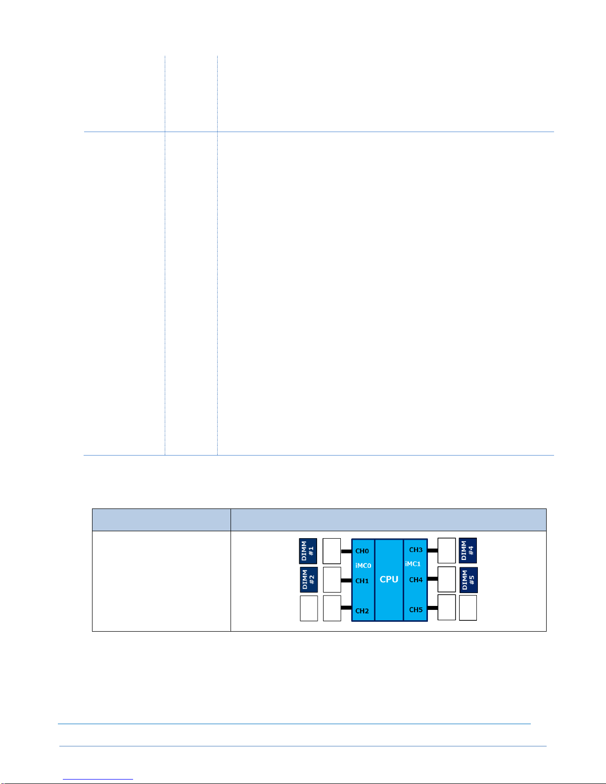
CONFIGURATION GUIDE – NEC Express5800/A2040e, A1040e
NEC Corporation Rev.1.0 – June 2018
39
CPU1・DIMM9&12 → CPU2・DIMM9&12 →
CPU3・DIMM9&12 → CPU4・DIMM9&12
At 1/2/3CPU configuration, please skip blank CPU in the installation order.
(*1) After 2CPU, when 6x DIMMs are installed per CPU, these DIMMs are to be
installed to DIMM3&6 (not DIMM7&8).
A2040e COPT
Decentraliz
ed
6 or less DIMM per CPU configuration
1CPUs with 6 or less DIMMs
2CPUs with 12 or less DIMMs
3CPUs with 18 or less DIMMs
4CPUs with 24 or less DIMMs
CPU1・DIMM1&2 → CPU1・DIMM4&5 → CPU1・DIMM3&6 →
CPU2・DIMM1&2 → CPU2・DIMM4&5 → CPU2・DIMM3&6 →
CPU3・DIMM1&2 → CPU3・DIMM4&5 → CPU3・DIMM3&6 →
CPU4・DIMM1&2 → CPU4・DIMM4&5 → CPU4・DIMM3&6
8 or more DIMM per CPU configuration
1CPUs with 7 or more DIMMs
2CPUs with 13 or more DIMMs
3CPUs with 19 or more DIMMs
4CPUs with 25 or more DIMMs
CPU1・DIMM1&2 → CPU1・DIMM4&5 → CPU1・DIMM7&8 →
CPU1・DIMM10&11 → CPU1・DIMM3&6 → CPU1・DIMM9&12 →
CPU2・DIMM1&2 → CPU2・DIMM4&5 → CPU2・DIMM7&8(*1) →
CPU2・DIMM10&11 → CPU2・DIMM3&6 → CPU2・DIMM9&12 →
CPU3・DIMM1&2 → CPU3・DIMM4&5 → CPU3・DIMM7&8(*1) →
CPU3・DIMM10&11 → CPU3・DIMM3&6 → CPU3・DIMM9&12 →
CPU4・DIMM1&2 → CPU4・DIMM4&5 → CPU4・DIMM7&8(*1) →
CPU4・DIMM10&11 → CPU4・DIMM3&6 → CPU4・DIMM9&12
At 1/2/3CPU configuration, please skip blank CPU in the installation order.
(*1) After 2CPU, when 6x DIMMs are installed per CPU, these DIMMs are to be
installed to DIMM3&6 (not DIMM7&8).
2-2. Memory Rank Sparing Mode
Installation in 1CPU
Configuration
Diagrams
4x DIMM
Page 40

CONFIGURATION GUIDE – NEC Express5800/A2040e, A1040e
NEC Corporation Rev.1.0 – June 2018
40
8x DIMM
12x DIMM
Installation at 1/2/3/4CPU configuration
Model
DIMM
Allocation
Installation Rules
A2040e
(standard)
A2040e COPT
model with
NE3300-SV801
A1040e
Distributed
For 32GB MEM for Memory Rank Sparing (4x8GB) and 64GB MEM for Memory
Rank Sparing (4x16GB), Sparing is only supported by 8x DIMM or 12 x DIMM
configuration (Sparing with 4x DIMM is NOT supported.).
CPU1・DIMM1&2&4&5 → CPU2・DIMM1&2&4&4 →
CPU3・DIMM1&2&4&5 → CPU4・DIMM1&2&4&5 →
CPU1・DIMM7&8&10&11 → CPU2・DIMM7&8&10&11 →
CPU3・DIMM7&8&10&11 → CPU4・DIMM7&8&10&11 →
CPU1・DIMM3&9&6&12 → CPU2・DIMM3&9&6&12 →
CPU3・DIMM3&9&6&12 → CPU4・DIMM3&9&6&12
At 1/2/3CPU configuration, please skip blank CPU in the installation order.
A2040e COPT
Decentraliz
ed
For 32GB MEM for Memory Rank Sparing (4x8GB) and 64GB MEM for Memory
Rank Sparing (4x16GB), Sparing is only supported by 8x DIMM or 12 x DIMM
configuration (Sparing with 4x DIMM is NOT supported.).
CPU1・DIMM1&2&4&5 → CPU1・DIMM7&8&10&11 → CPU1・DIMM3&9&6&12 →
CPU2・DIMM1&2&4&5 → CPU2・DIMM7&8&10&11 → CPU2・DIMM3&9&6&12 →
CPU3・DIMM1&2&4&5 → CPU3・DIMM7&8&10&11 → CPU3・DIMM3&9&6&12 →
CPU4・DIMM1&2&4&5 → CPU4・DIMM7&8&10&11 → CPU4・DIMM3&9&6&12
At 1/2/3CPU configuration, please skip blank CPU in the installation order.
2-3. Memory Mirroring Mode
Installation in 1CPU
Configuration
Diagrams
Page 41

CONFIGURATION GUIDE – NEC Express5800/A2040e, A1040e
NEC Corporation Rev.1.0 – June 2018
41
3x DIMM
6x DIMM
12x DIMM
Installation at 1/2/3/4CPU configuration
Model
DIMM
Allocation
Installation Rules
A2040e
(standard)
A2040e COPT
model with
NE3300-SV801
A1040e
Distributed
6 or less DIMM per CPU configuration
1CPUs with 6 or less DIMMs
2CPUs with 12 or less DIMMs
3CPUs with 18 or less DIMMs
4CPUs with 24 or less DIMMs
CPU1・DIMM1&2&3 → CPU2・DIMM1&2&3 →
CPU3・DIMM1&2&3 → CPU4・DIMM1&2&3 →
CPU1・DIMM4&5&6 → CPU2・DIMM4&5&6 →
CPU3・DIMM4&5&6 → CPU4・DIMM4&5&6
8 or more DIMM per CPU configuration
1CPUs with 7 or more DIMMs
2CPUs with 13 or more DIMMs
3CPUs with 19 or more DIMMs
4CPUs with 25 or more DIMMs
CPU1・DIMM1&2&3 → CPU2・DIMM1&2&3 →
CPU3・DIMM1&2&3 → CPU4・DIMM1&2&3 →
CPU1・DIMM4&5&6 → CPU2・DIMM4&5&6 →
CPU3・DIMM4&5&6 → CPU4・DIMM4&5&6 →
CPU1・DIMM7&8&9 → CPU2・DIMM7&8&9 →
CPU3・DIMM7&8&9 → CPU4・DIMM7&8&9 →
CPU1・DIMM10&11&12 → CPU2・DIMM10&11&12 →
CPU3・DIMM10&11&12 → CPU4・DIMM10&11&12
At 1/2/3CPU configuration, please skip blank CPU in the installation order.
Page 42

CONFIGURATION GUIDE – NEC Express5800/A2040e, A1040e
NEC Corporation Rev.1.0 – June 2018
42
A2040e COPT
Decentraliz
ed
6 or less DIMM per CPU configuration
1CPUs with 6 or less DIMMs
2CPUs with 12 or less DIMMs
3CPUs with 18 or less DIMMs
4CPUs with 24 or less DIMMs
CPU1・DIMM1&2&3 → CPU1・DIMM4&5&6 →
CPU2・DIMM1&2&3 → CPU2・DIMM4&5&6 →
CPU3・DIMM1&2&3 → CPU3・DIMM4&5&6 →
CPU4・DIMM1&2&3 → CPU4・DIMM4&5&6
8 or more DIMM per CPU configuration
1CPUs with 7 or more DIMMs
2CPUs with 13 or more DIMMs
3CPUs with 19 or more DIMMs
4CPUs with 25 or more DIMMs
CPU1・DIMM1&2&3 → CPU1・DIMM4&5&6 →
CPU1・DIMM7&8&9 → CPU1・DIMM10&11&12 →
CPU2・DIMM1&2&3 → CPU2・DIMM4&5&6 →
CPU2・DIMM7&8&9 → CPU2・DIMM10&11&12 →
CPU3・DIMM1&2&3 → CPU3・DIMM4&5&6 →
CPU3・DIMM7&8&9 → CPU3・DIMM10&11&12 →
CPU4・DIMM1&2&3 → CPU4・DIMM4&5&6 →
CPU4・DIMM7&8&9 → CPU4・DIMM10&11&12
At 1/2/3CPU configuration, please skip blank CPU in the installation order.
Page 43

CONFIGURATION GUIDE – NEC Express5800/A2040e, A1040e
NEC Corporation Rev.1.0 – June 2018
43
■Internal Drive
Internal Drive: Priority/Order of Installation
At the initial server delivery, internal drives are installed with the following priority/order. If the ordered
configuration is not in the scope of the rule, the drive will be delivered as not configured.
・Slot 0 => Slot 1 => Slot 2 => Slot 3 => Slot 4 => Slot 5 => Slot 6 => Slot 7
Conditions to Mix Internal Drives
Mixing HDDs with the same rotation speed is supported in the BTO configuration.
Mixing HDDs with different rotation speed and mixing HDD and SSD is NOT supported in the BTO
configuration.
Cannot mix the different drives within a RAID group (pack)
When defining hot spare disk under mixed drive configuration, need to set Dedicated Hot Spare per
RAID group. Global Hot Spare is not available.
Please refer to the following for further details.
With different internal drives
For a RAID Controller, 2 kinds of HDDs or HDD/SSD can be mixed.
- When SSDs with different capacity are mixed, smaller SSDs are installed first.
- When HDDs with different rotation speed, higher speed HDDs are installed first. If the speed is
the same, smaller capacity HDDs are installed first.
Page 44

CONFIGURATION GUIDE – NEC Express5800/A2040e, A1040e
NEC Corporation Rev.1.0 – June 2018
44
Page 45

CONFIGURATION GUIDE – NEC Express5800/A2040e, A1040e
NEC Corporation Rev.1.0 – June 2018
45
Standard RAID Configuration at the Initial Server Delivery
Standard RAID configuration for the same type of internal drives at the initial server delivery is as follows
RAID 50 and RAID 60 are not supported for BTO configuration
Controller
(reference section)
# of Drive
Standard RAID Configuration
NE3303-178
or
NE3303-177
4.2.1
4.2.2
(up to 8 drives)
1
RAID 0 (Q’ty 1)
2
RAID 1 (Q’ty 2)
3~8
RAID 1 (if the number of drive is odd, will set
one spare drive.)
NOTE:
Up to 4 RAID group (pack) per server
Need to order same capacity/rotation speed drives in one group (disk array) for RAID configuration at
BTO configuration.
Initial settings of RAID Controller is Write Through without Flash Back-up Unit. When needing higher
performance, recommend Write Back with Flash Back-up Unit..
(Please refer to the manual attached to the RAID Controller for the setting information.)
Page 46

CONFIGURATION GUIDE – NEC Express5800/A2040e, A1040e
NEC Corporation Rev.1.0 – June 2018
46
■Connection to RDX (USB) by Device Expansion Unit
Conditions to connect to RDX (USB)
When using Device Expansion Unit (1U) with the embedded RDX (USB) [N8151-125/-105], please
connect to USB connector on the rear side of the server. Not allowed to connect to USB connector of
SUV cable.
Please use an external USB cable of USB2.0 supported [K410-197(00)]. K410-307(1) for USB3.0 is not
available.
2m cable is necessary to connect between Device Expansion Unit and USB connector on the rear side
of the server. Therefore, please be aware of the following restrictions about the location of the Device
Expansion Unit:
- Device Expansion Unit [N8141-69] (1U)
1. Can locate within 2U from the top or bottom of the server.
2. Device 1 on the left side from the front (right connecter #1 from the rear) can be available.
Only HDD cartridge is available as Data Cartridge for Back-up (SSD cartridge is NOT available.)
RDX is not supported for VMware environment. Recommend the back-up through network, building back-
up server separately.
Page 47

CONFIGURATION GUIDE – NEC Express5800/A2040e, A1040e
NEC Corporation Rev.1.0 – June 2018
47
■Server Management
The EXPRESSSCOPE Engine SP3, integrated into the server (service processor (BMC)), provides superior
remote control and system management features listed in the table below.
Standard
Hardware Monitoring
Temperature/HDD/fan/voltage/power/RAID
Degradation (memory/HDD etc.)
Hardware configuration information collection
Hardware event log collection
Boot Monitoring
POST/BIOS stall, Booting, OS panic, Shutdown
1
Alerting
HW error, Boot error and OS panic
(by SNMP, E-mail)
3
Remote KVM (via LAN)
POST/BIOS setup, ROM utility
Boot screen, Panic screen
CUI-based screen (OS console)
GUI-based screen (OS console)
Remote Control (via LAN)
Remote reset/Power on-off/dump
Remote power capping
BIOS/BMC FW update
Remote BIOS setup (partial configuration only)
OS shutdown
1
Remote media (CD/DVD/FD/USB)
CLP (Command Line Protocol) (DMTF compliant)
Remote control via Web browser (multi user login at the
same time)
Scheduling (without UPS, ESMPRO/SM required)
1
Maintenance
EXPRESSSCOPE® Profile Key (Backup/restore
BIOS/BMC setup information)
Others
Set automatic IP address via DNS/DHCP
LDAP/Active Directory verification/user control
Clock synchronization of main unit and the RTC
Access log collection
IPv6 supported (Web console/CLP/e-mail alert)
BMC Failover
When master BMC fails, switch to stand-by BMC
2
Industry standard
IPMI
2.0
1
Not supported under VMware environment
2
Features to recovery EXPRESSSCOPE Engine SP3 itself. Supoprted only for A2040d/A2020d/A2010d.
For A2010d, reboot required to failover to stand-by BMC. Need to connect master and stand-by BMC to 2
Management LAN interface from 2 Management LAN ports.
3
For alerting via e-mail by BMC, management LAN port needs to be connected to management LAN interface and IP
address and alert address need to be set/defined.
Page 48

CONFIGURATION GUIDE – NEC Express5800/A2040e, A1040e
NEC Corporation Rev.1.0 – June 2018
48
■PCI Slot: Available Slots and Installation Limitations
A2040e (including COPT model)
Available Slots Matrix (general)
Installation Limitations due to I/O Space
Some PCI cards using I/O space has limitation regarding the number of cards to be installed. Please see the tables
below.
NOTE:
Please refer to the Users Guide of each card for the details.
“Card Perf.” means the maximum operating performance of the card.
If the PCI slot specification is lower than the operation performance of the cards, the card operates according to the specification
of the slot.
PCI Slot #2 to #16 are hot plug supported.
Product Code
PCI Slot Specifications #16 #15 #14 #13 #12 #11 #10 #9 #1 #2 #3 #4 #5 #6 #7 #8
x16 x16 x8 x8 x16 x16 x8 x8 x8 x8 x16 x16 x8 x8 x16 x16
x16 x16 x8 x8 x16 x16 x8 x8 x8 x8 x16 x16 x8 x8 x16 x16
4 9 13
16
NE3303-178
- - - - - - - -
Y
- - - - - - -
NE3303-177
- - - - - - - - Y - - - - - - -
NE3303-H004 - Y Y Y Y Y Y Y Y Y Y Y Y Y Y Y 3 7 11 14
To connect to Disk
Expansion Unit
Flash Backup Unit
[NE3303-H102] can be
added *3*4
NE3303-184
-
Y Y Y Y Y Y Y Y Y Y Y Y Y Y Y 3 7 11 14
NE3390-157A Y Y Y Y Y Y Y Y Y Y Y Y Y Y Y Y 3 7 11 15
NE3390-158A Y Y Y Y Y Y Y Y Y Y Y Y Y Y Y Y 3 7 11 15
NE3304-151M Y Y
Y
*1,2
Y Y Y
Y
*1,2
Y
Y
Y
*1,2
Y Y Y
Y
*1,2
Y Y
4 8 12 16
NE3304-152M Y Y Y*2 Y Y Y Y*2 Y Y Y*2 Y Y Y Y*2 Y Y 4 8 12 16
NE3304-158 Y Y Y*2 Y Y Y Y*2 Y Y Y*2 Y Y Y Y*2 Y Y 3 7 11 15
NE3304-159 Y Y
Y
*2,5
Y Y Y
Y
*2,5
Y
Y
Y
*2,5
Y Y Y
Y
*2,5
Y Y
3 7 11 15
NE3304-157 Y Y Y*2 Y Y Y Y*2 Y Y Y*2 Y Y Y Y*2 Y Y 4 8 12 16
*3 With Flash Backup Unit installed, up to 2 x External RAID Controller can be installed to PCI Slot#2,#3,#4,#5,#6 and up to 2 x External RAID Controller can be installed to PCI Slot#10,#11,#12,#13,#14.
*4 When installing RAID contoller (NE3304-177/NE3304-178) with Flash Backup Unit, up to 1 x External RAIC Controller with Flash Backup Unit can be installed to PCIe Slot#2,#3,#4,#5,#6.
*5 Not supporting PXE Boot with 2 x NE3304-159 (i.e. enabling 2 x Option ROM).
10GBASE-Tadapter (2port)
(Card Perf.: PCI Express 3.0(x4))
For LAN connection
*1 WOL (Wake On LAN) / PXE (Preboot eXecution Environment) boot supported
*2 PXE(Preboot eXecution Environment) boot supported
10GBASE Adapter (QSFP+/4ch)
(Card Perf.: PCI Express 3.0(x8))
For LAN connection
Need to separately order QSFP+ Module
[NE3304-161], when necessary
1000BASE-T Adapter (2port)
(Card Perf.: PCI Express 2.0(x1))
For LAN connection
Physical Card: PCI Express 2.0(x4)
1000BASE-T Adapter (4port)
(Card Perf.: PCI Express 2.0(x4))
For LAN connection.
LAN cables with RJ-45 plug covers cannot be used
10GBASE Adapter (SFP+/2ch)
(Card Perf.: PCI Express 2.0(x8))
For LAN connection
Need to separately order SFP+ Module
[NE3304-129], when necessary
16
To connect to internal disks
Flash Backup Unit
[NE3303-H101] can be
added
RAID Controller
(1GB, RAID 0/1/5/6)
(Card Perf.: PCI Express 3.0(x8))
External RAID Controller
(2GB, RAID 0/1/5/6)
(Card Perf.: PCI Express 3.0(x8))
SAS Controller
(12Gb/s SAS)
(Card Perf.: PCI Express 3.0(x8))
Fibre Channel Controller (1port)
(16Gbps/Optical)
(Card Perf.: PCI Express 3.0(x8))
Fibre Channel Controller (2port)
(16Gbps/Optical)
(Card Perf.: PCI Express 3.0(x8))
167.65mm >
Available Slot
Total
Name/Description
RAID Controller
(2GB, RAID 0/1/5/6)
(Card Perf.: PCI Express 3.0(x8))
111
1
PCIe Slot
Max. Number of Cards
for Installation
Note
PCIe 3.0
8Gb/s
Low Profile
Product Code
NE3303-H004
NE3303-184
Name/Description
RAIDController
(2GB, RAID 0/1/5/6)
SASController
(12Gb/s SAS)
# of Available
Slot
#16 #15 #14 #13 #12 #11 #10 #9 #1 #2 #3 #4 #5 #6 #7 #8
4
8
12
16
—
No limitation
No limitation
No limitation
Slot#13,#14,#15 only
No limitation
No limitation
No limitation
PCIe Slot
—
—
No limitation
———
No limitation
No limitation
Page 49

CONFIGURATION GUIDE – NEC Express5800/A2040e, A1040e
NEC Corporation Rev.1.0 – June 2018
49
A1040e
Available Slots Matrix (general)
Product Code
PCI Slot Specifications #16 #15 #14 #13 #12 #11 #10 #9 #1 #2 #3 #4 #5 #6 #7 #8
x16 x16 x8 x8 x16 x16 x8 x8 x8 x8 x16 x16 x8 x8 x16 x16
x16 x16 x8 x8 x16 x16 x8 x8 x8 x8 x16 x16 x8 x8 x16 x16
4 9 13
16
NE3303-178
- - - - - - - - Y - - - - - - -
NE3303-177 - - - - - - - - Y - - - - - - -
NE3303-H004 - Y - - Y Y Y - Y Y Y Y Y Y Y Y 3 7 10 12
To connect to Disk
Expansion Unit
Flash Backup Unit
[NE3303-H102] can
be added *3*4
NE3303-184
- Y - - Y Y Y - Y Y Y Y Y Y Y Y
3 7 10 12
NE3390-157A
Y Y - - Y Y Y - Y Y Y Y Y Y Y Y
3 7 10 12
NE3390-158A Y Y - - Y Y Y - Y Y Y Y Y Y Y Y 3 7 10 12
NE3304-151M Y Y - - Y Y
Y
*1,2
-
Y
Y
*1,2
Y Y Y
Y
*1,2
Y Y
4 8 11 13
NE3304-152M Y Y - - Y Y Y*2 - Y Y*2 Y Y Y Y*2 Y Y 4 8 11 13
NE3304-158 Y Y - - Y Y Y* 2 - Y Y *2 Y Y Y Y*2 Y Y 3 7 11 12
NE3304-159 Y Y - - Y Y
Y
*2,5
-
Y
Y
*2,5
Y Y Y
Y
*2,5
Y Y
3 7 11 12
NE3304-157
Y Y - - Y Y Y* 2 - Y Y *2 Y Y Y Y*2 Y Y
4 8 11 12
*3 With Flash Backup Unit installed, up to 2 x External RAID Controller can be installed to PCI Slot#2,#3,#4,#5,#6 and up to 2 x External RAID Controller can be installed to PCI Slot#10,#11,#12,#13,#14.
*4 When installing RAID contoller (NE3304-177/NE3304-178) with Flash Backup Unit, up to 1 x External RAIC Controller with Flash Backup Unit can be installed to PCIe Slot#2,#3,#4,#5,#6.
*5 Not supporting PXE Boot with 2 x NE3304-159 (i.e. enabling 2 x Option ROM).
10GBASE-Tadapter (2port)
(Card Perf.: PCI Express 3.0(x4))
For LAN connection
*1 WOL (Wake On LAN) / PXE (Preboot eXecution Environment) boot supported
*2 PXE(Preboot eXecution Environment) boot supported
10GBASE Adapter (QSFP+/4ch)
(Card Perf.: PCI Express 3.0(x8))
For LAN connection
Need to separately order QSFP+ Module
[NE3304-161], when necessary
1000BASE-T Adapter (2port)
(Card Perf.: PCI Express 2.0(x1))
For LAN connection
Physical Card: PCI Express 2.0(x4)
1000BASE-T Adapter (4port)
(Card Perf.: PCI Express 2.0(x4))
For LAN connection.
LAN cables with RJ-45 plug covers cannot be used
10GBASE Adapter (SFP+/2ch)
(Card Perf.: PCI Express 2.0(x8))
For LAN connection
Need to separately order SFP+ Module
[NE3304-129], when necessary
13
To connect to internal disks
Flash Backup Unit
[NE3303-H101] can
be added
RAID Controller
(1GB, RAID 0/1/5/6)
(Card Perf.: PCI Express 3.0(x8))
External RAID Controller
(2GB, RAID 0/1/5/6)
(Card Perf.: PCI Express 3.0(x8))
SAS Controller
(12Gb/s SAS)
(Card Perf.: PCI Express 3.0(x8))
Fibre Channel Controller (1port)
(16Gbps/Optical)
(Card Perf.: PCI Express 3.0(x8))
Fibre Channel Controller (2port)
(16Gbps/Optical)
(Card Perf.: PCI Express 3.0(x8))
167.65mm >
Available Slot
Total
Name/Description
RAID Controller
(2GB, RAID 0/1/5/6)
(Card Perf.: PCI Express 3.0(x8))
111
1
PCIe Slot
Max. Number of Cards
for Installation
Note
PCIe 3.0
8Gb/s
Low Profile
Page 50

CONFIGURATION GUIDE – NEC Express5800/A2040e, A1040e
NEC Corporation Rev.1.0 – June 2018
50
Installation Limitations for Windows Environment
For Windows environment, PCI cards have additional installation limitations as for the number of the cards to be installed,
depending on the combination of the PCI cards and CPU. Please refer below for the details.
In case of using CPU SKU with small number of thread and require large I/O space, Hyper Threading is recommended
to “ON” (default setting) in order to avoid performance decrease due to lack of I/O space.
Windows Hyper-Threading = ON
28C 24C 18C 12C 10C 8C 4C
Product Code Model
CPU
Platinum 8180M
Platinum 8180
Platinum 8176M
Platinum 8176
Platinum 8160
Gold 6150 Gold 6136 Gold 5155 Gold 6144
Platinum 8156
Gold 5122
NE3303-178
NE3303-177
NE3303-H004
NE3303-184
NE3390-157A
NE3390-158A
Max. 2 cards per
CPU
NE3304-151M
NE3304-152M
NE3304-158
NE3304-159
NE3304-157
*1 Max. number of slots depends on the number of CPU: Max. slot
A2040e: 1CPU: 4slots, 2CPU: 8slots, 3CPU:12slots, 4CPU:16slots
A1040e: 1CPU: 4slots, 2CPU: 8slots, 3CPU:11slots, 4CPU:13slots
10GBASE-Tadapter (2port)
Max. 7 cards per server
Max. # of slots *1
16/13
1000BASE-T Adapter (4port)
Max. 14 cards per server
10GBASE Adapter (SFP+/2ch)
Same as "Available Slots Matrix (general)"
10GBASE Adapter (QSFP+/4ch)
Windows not supported
SAS Controller
(12Gb/s SAS)
Same as "Available Slots Matrix (general)"
Fibre Channel Controller (1port)
(16Gbps/Optical)
Same as "Available Slots Matrix (general)"
Fibre Channel Controller (2port)
(16Gbps/Optical)
1000BASE-T Adapter (2port)
Same as "Available Slots Matrix (general)"
A2040e/A1040e
Name/Description
RAID Controller
(2GB, RAID 0/1/5/6)
Same as "Available Slots Matrix (general)"
RAID Controller
(1GB, RAID 0/1/5/6)
External RAID Controller
(2GB, RAID 0/1/5/6)
Page 51

CONFIGURATION GUIDE – NEC Express5800/A2040e, A1040e
NEC Corporation Rev.1.0 – June 2018
51
Windows Hyper-Threading = OFF
Product Code Model
CPU
Platinum 8180M
Platinum 8180
Platinum 8176M
Platinum 8176
Platinum 8160
Gold 6150 Gold 6136 Gold 5155 Gold 6144
Platinum 8156
Gold 5122
NE3303-178
NE3303-177
NE3303-H004
Max. 3 cards per
CPU
NE3303-184
NE3390-157A
NE3390-158A
Max. 3 cards per
CPU
Max. 2 cards per
CPU
Max. 1 card per
CPU
NE3304-151M
NE3304-152M
NE3304-158
NE3304-159
NE3304-157
A2040e/A1040e
Name/Description
RAID Controller
(2GB, RAID 0/1/5/6)
Same as "Available Slots Matrix (general)"
RAID Controller
(1GB, RAID 0/1/5/6)
External RAID Controller
(2GB, RAID 0/1/5/6)
SAS Controller
(12Gb/s SAS)
Same as "Available Slots Matrix (general)"
Max. 2 cards per
CPU
Fibre Channel Controller (1port)
(16Gbps/Optical)
Fibre Channel Controller (2port)
(16Gbps/Optical)
Same as "Available Slots Matrix (general)"
1000BASE-T Adapter (2port)
Same as "Available Slots Matrix (general)"
1000BASE-T Adapter (4port)
Max. 14 cards per server
10GBASE Adapter (SFP+/2ch)
Same as "Available Slots Matrix (general)"
*1 Max. number of slots depends on the number of CPU: Max. slot
A2040e: 1CPU: 4slots, 2CPU: 8slots, 3CPU:12slots, 4CPU:16slots
A1040e: 1CPU: 4slots, 2CPU: 8slots, 3CPU:11slots, 4CPU:13slots
Max. # of slots *1
16/13
10GBASE Adapter (QSFP+/4ch)
Windows not supported
10GBASE-Tadapter (2port)
Max. 7 cards per server
Page 52

CONFIGURATION GUIDE – NEC Express5800/A2040e, A1040e
NEC Corporation Rev.1.0 – June 2018
52
Installation Limitations for VMware
For VMware environment, PCI cards have limitations as for the number of the cards to be installed, depending
on the combination of the PCI cards. Please refer below for the details.
VMware ESXi6.5 (including Update)
Limitation by VMware ESXi6.5
(1) RAID Controller, SAS Controller
・ The same number of the contoroller as the number of CPU can be installed.
(2) LAN Baords
・ 1Gb: Max. 16 ports
・ 10Gb: Max. 8 ports (NE3304-158), Max. 8 ports (NE3304-159), Max 16 ports (NE3304-157)
・ Combination of 1Gb/10Gb: Max. 16 ports for 10Gb and max. 4 ports for 1Gb
(For 10Gb: NE3304-158/159 should be up to 8 ports in total, NE3304-157 should be upt o 16 ports)
(3) FC Controller
・ 8Gb/16Gb :Max. 8 card in total and Max. 16 ports in total
Note: Please refer to the following site for details:
https://docs.vmware.com/en/VMware-vSphere/6.5/vsp-esxi-vcenter-server-651-configuration-maximums-guide.pdf
Limitation by the combination of CPU and PCI Cards
Product Code Model
CPU
Example1 Example2 Example3 Example4 Example5 Example6
NE3303-178
NE3303-177
NE3303-H004 - - -
NE3303-184 - - -
NE3390-157A
NE3390-158A
NE3304-151M Max. 5 cards *2 Max. 8 cards *2 -*2 -*2 Max. 1 card *2 Max. 1 card *2
NE3304-152M -*2 -*2 Max. 4 card *2 -*2 -*2 -*2
NE3304-158 -*2 -*2 -*2 Max. 2 card *2 -*2
NE3304-159 -*2 -*2 Max. 2 card *2 -*2 -*2
NE3304-157 -*2 -*2 -*2 -*2 -*2 -*2
16 16 13 15 16 16
In addition to the above, please also follow "Available Slots Matrix (general)" and "Installation Limitations due to I/O Space".
*1 Max. number of slots depends on the number of CPU: Max. slot
A2040e: 1CPU: 4slots, 2CPU: 8slots, 3CPU:12slots, 4CPU:16slots
A1040e: 1CPU: 4slots, 2CPU: 8slots, 3CPU:11slots, 4CPU:13slots
*2 For Lan card and FC Contoller, please follow "Limitation by VMware ESXi6.5".
Max. 1 card in total
Name/Description
RAID Controller
(2GB, RAID 0/1/5/6)
RAID Controller
(1GB, RAID 0/1/5/6)
Max. 8 cards in
total *2
Max. 2 cards in
total *2
Max. 7 cards in
total *2
External RAID Controller
(2GB, RAID 0/1/5/6)
Max. 1 card in total
Max. 1 card in total
Max. 8 cards in
total *2
10GBASE-Tadapter (2port)
1000BASE-T Adapter (4port)
10GBASE Adapter (SFP+/2ch)
A2040e/A1040e
All CPUs
Fibre Channel Controller (2port)
(16Gbps/Optical)
SAS Controller
(12Gb/s SAS)
Max. 1 card in total
Max. 8 cards in
total *2
Max. 3 cards in
total
Max. 1 card in total
Max. 1 card in total
Max. 3 cards in
total
Max. 3 cards in
total
Max. 7 cards in
total *2
Max. 3 cards in
total *2
Fibre Channel Controller (1port)
(16Gbps/Optical)
1000BASE-T Adapter (2port)
Max. # of slots *1
10GBASE Adapter (QSFP+/4ch)
Page 53

CONFIGURATION GUIDE – NEC Express5800/A2040e, A1040e
NEC Corporation Rev.1.0 – June 2018
53
■PCI Card: Priority/Order of Installation
Starting from the PCI cards with higher priority (see the table below), PCI cards are installed to the PCI slots with higher
priority among the available slots per CPU configuration (see the table below). The following basic rules are applied to
BTO configuration. If any other specific installation requirements, BTO configuration will not be applied.
[Basic Rules for PCI Card Installation]
RAID Controller: up to 1 controller can be installed to Slot#1.
SAS Controller:
(A2040e) up to 4 controller can be installed to Slot#3, #7, #9 and #15.
(A1040e) up to 3 controller can be installed to Slot#3, #7 and #15.
NIC: At least 1 card needs to be installed among 1000BASE-T Adapter (2ch/4ch), 10GBASE-T Adapter.
A2040e (including COPT model)
PCIe Slot
Product Code
PCI Slot Specifications #16 #15 #14 #13 #12 #11 #10 #9 #1 #2 #3 #4 #5 #6 #7 #8
x16 x16 x8 x8 x16 x16 x8 x8 x8 x8 x16 x16 x8 x8 x16 x16
x16 x16 x8 x8 x16 x16 x8 x8 x8 x8 x16 x16 x8 x8 x16 x16
High NE3303-177
- - - - - - - -
[1]
- - - - - - -
1
NE3303-178
- - - - - - - - [1] - - - - - - -
1
NE3303-H004
- - - - [3] [2] - - - - - [4] [1] - - -
4
To connect to Disk
Expansion Unit
Flash Backup Unit
[NE3303-H102] can be
added *3*4
NE3303-184
- [4] - - - - - [3] - - [1] - - - [2] -
4
NE3304-151M
[8] [12] [4] [16] [7] [11] [3] [15] [13] [1] [9] [5] [14] [2] [10] [6]
16
NE3304-152M
[8] [12] [4] [16] [7] [11] [3] [15] [13] [1] [9] [5] [14] [2] [10] [6]
16
NE3304-159
[8] [12] [4] [16] [7] [11] [3] [15] [13] [1] [9] [5] [14] [2] [10] [6]
16
NE3304-157
[8] [12] [4] [16] [7] [11] [3] [15] [13] [1] [9] [5] [14] [2] [10] [6]
16
NE3304-158
[8] [12] [4] [16] [7] [11] [3] [15] [13] [1] [9] [5] [14] [2] [10] [6]
16
NE3390-158A
[8] [12] [4] [16] [7] [11] [3] [15] [13] [1] [9] [5] [14] [2] [10] [6]
15
Low
NE3390-157A
[8] [12] [4] [16] [7] [11] [3] [15] [13] [1] [9] [5] [14] [2] [10] [6]
15
When another card is already installed in a slot, the card will be installed to the slot with next priority.
Note:
PCI cards with higher priority as shown above ("high" to "low") are to be installaled first. The number in the list (shown with [ ]) shows the priority of the slots for each card to be installed. "-" shows the card cannot be
10GBASE-Tadapter (2port)
(Card Perf.: PCI Express 3.0(x4))
For LAN connection
10GBASE Adapter (SFP+/2ch)
(Card Perf.: PCI Express 2.0(x8))
For LAN connection
Need to separately order SFP+ Module
[NE3304-129], when necessary
Fibre Channel Controller (2port)
(16Gbps/Optical)
(Card Perf.: PCI Express 3.0(x8))
Fibre Channel Controller (1port)
(16Gbps/Optical)
(Card Perf.: PCI Express 3.0(x8))
1000BASE-T Adapter (2port)
(Card Perf.: PCI Express 2.0(x1))
For LAN connection
Physical Card: PCI Express 2.0(x4)
1000BASE-T Adapter (4port)
(Card Perf.: PCI Express 2.0(x4))
For LAN connection.
LAN cables with RJ-45 plug covers cannot be used
10GBASE Adapter (QSFP+/4ch)
(Card Perf.: PCI Express 3.0(x8))
For LAN connection
Need to separately order QSFP+ Module
[NE3304-161], when necessary
RAID Controller
(1GB, RAID 0/1/5/6)
(Card Perf.: PCI Express 3.0(x8))
To connect to internal disks
Flash Backup Unit
[NE3303-H101] can be
added
RAID Controller
(2GB, RAID 0/1/5/6)
(Card Perf.: PCI Express 3.0(x8))
External RAID Controller
(2GB, RAID 0/1/5/6)
(Card Perf.: PCI Express 3.0(x8))
SAS Controller
(12Gb/s SAS)
(Card Perf.: PCI Express 3.0(x8))
Priority
Max. No. of
Available
Slots
Note
PCIe 3.0
8Gb/s
Low Profile
167.65mm >
Name/Description
Page 54

CONFIGURATION GUIDE – NEC Express5800/A2040e, A1040e
NEC Corporation Rev.1.0 – June 2018
54
A1040e
PCIe Slot
Product Code
PCI Slot Specifications #16 #15 #14 #13 #12 #11 #10 #9 #1 #2 #3 #4 #5 #6 #7 #8
x16 x16 x8 x8 x16 x16 x8 x8 x8 x8 x16 x16 x8 x8 x16 x16
x16 x16 x8 x8 x16 x16 x8 x8 x8 x8 x16 x16 x8 x8 x16 x16
高 NE3303-177
- - - - - - - -
[1]
- - - - - - -
1
NE3303-178
- - - - - - - - [1] - - - - - - -
1
NE3303-H004
- - - - [3] [2] - - - - - [4] [1] - - -
4
To connect to Disk
Expansion Unit
Flash Backup Unit
[NE3303-H102] can be
added *3*4
NE3303-184
- [3] - - - - - - - - [1] - - - [2] -
3
NE3304-151M
[7] [11] - - [6] [10] [3] - [12] [1] [8] [4] [13] [2] [9] [5]
13
NE3304-152M
[7] [11] - - [6] [10] [3] - [12] [1] [8] [4] [13] [2] [9] [5]
13
NE3304-159
[7] [11] - - [6] [10] [3] - [12] [1] [8] [4] [13] [2] [9] [5]
13
NE3304-157
[7] [11] - - [6] [10] [3] - [12] [1] [8] [4] [13] [2] [9] [5]
13
NE3304-158
[7] [11] - - [6] [10] [3] - [12] [1] [8] [4] [13] [2] [9] [5]
13
NE3390-158A
[7] [11] - - [6] [10] [3] - [12] [1] [8] [4] [13] [2] [9] [5]
12
低
NE3390-157A
[7] [11] - - [6] [10] [3] - [12] [1] [8] [4] [13] [2] [9] [5]
12
When another card is already installed in a slot, the card will be installed to the slot with next priority.
Fibre Channel Controller (2port)
(16Gbps/Optical)
(Card Perf.: PCI Express 3.0(x8))
Fibre Channel Controller (1port)
(16Gbps/Optical)
(Card Perf.: PCI Express 3.0(x8))
Note:
PCI cards with higher priority as shown above ("high" to "low") are to be installaled first. The number in the list (shown with [ ]) shows the priority of the slots for each card to be installed. "-" shows the card cannot be
10GBASE Adapter (QSFP+/4ch)
(Card Perf.: PCI Express 3.0(x8))
For LAN connection
Need to separately order QSFP+ Module
[NE3304-161], when necessary
10GBASE-Tadapter (2port)
(Card Perf.: PCI Express 3.0(x4))
For LAN connection
10GBASE Adapter (SFP+/2ch)
(Card Perf.: PCI Express 2.0(x8))
For LAN connection
Need to separately order SFP+ Module
[NE3304-129], when necessary
SAS Controller
(12Gb/s SAS)
(Card Perf.: PCI Express 3.0(x8))
1000BASE-T Adapter (2port)
(Card Perf.: PCI Express 2.0(x1))
For LAN connection
Physical Card: PCI Express 2.0(x4)
1000BASE-T Adapter (4port)
(Card Perf.: PCI Express 2.0(x4))
For LAN connection.
LAN cables with RJ-45 plug covers cannot be used
Name/Description
RAID Controller
(1GB, RAID 0/1/5/6)
(Card Perf.: PCI Express 3.0(x8))
To connect to internal disks
Flash Backup Unit
[NE3303-H101] can be
added
RAID Controller
(2GB, RAID 0/1/5/6)
(Card Perf.: PCI Express 3.0(x8))
External RAID Controller
(2GB, RAID 0/1/5/6)
(Card Perf.: PCI Express 3.0(x8))
Priority
Max. No. of
Available
Slots
Note
PCIe 3.0
8Gb/s
Low Profile
167.65mm >
Page 55

CONFIGURATION GUIDE – NEC Express5800/A2040e, A1040e
NEC Corporation Rev.1.0 – June 2018
55
■RAS Feature Matrix (per OS)
(1/2)
RAS Features
OS
A2040e
A1040e
Note
CPU Core Predictive
Failure Analysis (PFA)
RHEL7
Y
Y
*1
WS2016
Y
Y
*2
ESXi6.5
Y
Y
Dynamic CPU Core De-
allocation
RHEL7 Y N
*1
WS2016 N N
ESXi6.5 N N
Dynamic Memory Page
De-allocation
(Memory Page Offline)
RHEL7 Y N
*1
WS2016
Y
Y
*2
ESXi6.5
Y
Y
PCIe Hot-Add
PCIe Hot-Remove
RHEL7 Y N
WS2016 N N
ESXi6.5 N N
Static COPT
Reboot Required
(COPT Model)
RHEL7
Y(COPT)
N
*4
WS2016
Y(COPT)
N
*5
ESXi6.5
Y(COPT)
N
Dynamic COPT
Core Enabling
(COPT Model)
RHEL7
Y(COPT)
N
*1
WS2016 N N
ESXi6.5 N N
Dynamic COPT
CORE Sparing
(COPT Model)
RHEL7
Y(COPT)
N
*1
WS2016 N N
ESXi6.5 N N
Page 56

CONFIGURATION GUIDE – NEC Express5800/A2040e, A1040e
NEC Corporation Rev.1.0 – June 2018
56
(2/2)
RAS Features
OS
A2040d
A1040d
Note
DIMM Multi Rank Sparing
Y
Y
DDR4 Recovery
Y
Y
Address Based Memory
Mirroring
RHEL7 Y N
*1
WS2016 N N
ESXi6.5 N N
Reliable Memory
RHEL7
N
N
WS2016
N
N
ESXi6.5
Y
Y
MCA Recovery
RHEL7
Y
Y
WS2016
Y
Y
ESXi6.5
Y
Y
Enhanced MCA Recovery
Gen 2
(BIOS MCA Recovery on
Gen2 MCA; added by
E7v3 gen.)
RHEL7
Y
Y
WS2016
Y
Y
ESXi6.5
Y
Y
PCIe Live Error Recovery
RHEL7
Y
Y
*1
WS2016 N N
ESXi6.5 N N
Mission Critical I/O
Failover (Windows)
WS2016
Y
Y
*6
Page 57

CONFIGURATION GUIDE – NEC Express5800/A2040e, A1040e
NEC Corporation Rev.1.0 – June 2018
57
Legend for OS
WS2016
Windows Server 2016
RHEL7
Red Hat Enterprise Linux 7.4
ESXi6.5
VMware ESXi 6.5 update1
NOTE:
*1 Please install the necessary module according to the documents; “Machine Check Monitoring Service
User's Guide” and “Capacity Optimization (COPT) User's Guide for Linux”. They are additional modules for
a specific kernel version.
*2 Please install support kit (UPDATE module) in the EXPRESSBUILDER. With Windows Seamless Install,
the necessary modules are automatically installed.
*3 (intentionally blanked)
*4 As an option, if you install the necessary module acccording to the documents; “Machine Check
Monitoring Service User's Guide” “Capacity Optimization (COPT) User's Guide for Linux”, core allocation
among CPUs can be adjusted.
*5 As an option, if you install the necessary module according to the documents “Capacity Optimization
(COPT) User's Guide for Windows”, core allocation among CPUs can be adjusted.
*6 Please install the necessary module according to the document; "necmemras User's Guide for Linux" .
They are additional modules for a specific kernel version.
Page 58

CONFIGURATION GUIDE – NEC Express5800/A2040e, A1040e
NEC Corporation Rev.1.0 – June 2018
58
Copyright Notice and Liability Disclaimer
The information contained herein is subject to change without notice.
Microsoft and Windows Server are either registered trademarks or trademarks of Microsoft Corporation in the
United States and/or other countries
Intel and Xeon are registered trademarks or trademarks of Intel Corporation or its subsidiaries in the United
States and other countries.
Linux is a trademark of Linus Torvalds.
Red Hat is a registered trademark of Red Hat, Inc. in the U.S.
All other products, brands, or trade names used in this document are trademarks or registered trademarks of
their respective holders.
NEC shall not be liable for technical or editorial errors or omissions contained herein.
For hard drive capacity measurements, 1 GB = 1 billion bytes. Actual formatted capacity is less.
Page 59

CONFIGURATION GUIDE – NEC Express5800/A2040e, A1040e
NEC Corporation Rev.1.0 – June 2018
59
Revision History
Revision
Date
Description
Rev.1.0
June 2018
Initial Release
 Loading...