

Page 1

1. Installing Cabinets
2. PCB Installation and
Startup
3. Installing Extensions
and Trunks
4. Telephones and
Optional Equipment
5. Data and SMDR
6. LAN Connection
7. Specifications and
Parts
Hardware Manual
04.04
Technical Support Web Site:
http://ws1.necii.com (registration is required)
Page 2

This manual has been developed by NEC Unified Solutions, Inc. It is intended for the use of its customers and
service personnel, and should be read in its entirety before attempting to install or program the system. Any
comments or suggestions for improving this manual would be appreciated. Forward your remarks to:
NEC Unified Solutions, Inc.
4 Forest Parkway
Shelton, CT 06484
necunifiedsolutions.com
Nothing contained in this manual shall be deemed to be, and this manual does not constitute, a warranty of, or
representation with respect to, any of the equipment covered. This manual is subject to change without notice and
NEC Unified Solutions, Inc. has no obligation to provide any updates or corrections to this manual. Further, NEC
Unified Solutions, Inc. also reserves the right, without prior notice, to make changes in equipment design or
components as it deems appropriate. No representation is made that this manual is complete or accurate in all
respects and NEC Unified Solutions, Inc. shall not be liable for any errors or omissions. In no event shall NEC Unified
Solutions, Inc. be liable for any incidental or consequential damages in connection with the use of this manual. This
document contains proprietary information that is protected by copyright. All rights are reserved. No part of this
document may be photocopied or reproduced without prior written consent of NEC Unified Solutions, Inc.
©2005 by NEC Unified Solutions, Inc. All Rights Reserved.
Printed in U.S.A.
Page 3

Table of Contents
Table of Contents
Section 1:
Installing the Cabinet . . . . . . . . . . . . . . . . . . . . . . . . . . . . . . . . . . . . . . . . . . . . . . . . . . . . . . . 1-1
GENERAL PRECAUTIONS . . . . . . . . . . . . . . . . . . . . . . . . . . . . . . . . . . . . . . . . . . . . . . . . 1-1
INSTALLING THE CABINET . . . . . . . . . . . . . . . . . . . . . . . . . . . . . . . . . . . . . . . . . . . . . . 1-1
Unpacking. . . . . . . . . . . . . . . . . . . . . . . . . . . . . . . . . . . . . . . . . . . . . . . . . . . . . . . . . 1-1
Before Installing . . . . . . . . . . . . . . . . . . . . . . . . . . . . . . . . . . . . . . . . . . . . . . . . . . . . 1-1
Site Requirements. . . . . . . . . . . . . . . . . . . . . . . . . . . . . . . . . . . . . . . . . . . . . . . . . . . 1-2
Environmental Requirements . . . . . . . . . . . . . . . . . . . . . . . . . . . . . . . . . . . . . . . . . . 1-2
Removing the Front Cover (Figure 1-1). . . . . . . . . . . . . . . . . . . . . . . . . . . . . . . . . . 1-2
Securing the Cabinet to the Floor (Figure 1-2 - Figure 1-4) . . . . . . . . . . . . . . . . . . 1-4
Securing the Cabinet to the Wall (Figure 1-5 - Figure 1-8) . . . . . . . . . . . . . . . . . . . 1-7
Securing the Cabinet to a Rack (Figure 1-9 - Figure 1-12) . . . . . . . . . . . . . . . . . . 1-10
INSTALLING THE PCBS . . . . . . . . . . . . . . . . . . . . . . . . . . . . . . . . . . . . . . . . . . . . . . . . . 1-14
PCB Installation (Figure 1-13 - Figure 1-16) . . . . . . . . . . . . . . . . . . . . . . . . . . . . . 1-14
GROUNDING THE CABINETS . . . . . . . . . . . . . . . . . . . . . . . . . . . . . . . . . . . . . . . . . . . . 1-18
Connecting the System Ground (Figure 1-17) . . . . . . . . . . . . . . . . . . . . . . . . . . . . 1-18
COMPLETING THE INSTALLATION . . . . . . . . . . . . . . . . . . . . . . . . . . . . . . . . . . . . . . 1-20
Setting the Cable Pass-Through (Figure 1-18 - Figure 1-20). . . . . . . . . . . . . . . . . 1-20
Reinstalling the Front Cover (Figure 1-21 - Figure 1-22) . . . . . . . . . . . . . . . . . . . 1-22
Section 2:
PCB Installation and Startup . . . . . . . . . . . . . . . . . . . . . . . . . . . . . . . . . . . . . . . . . . . . . . . . . . 2-1
PCB LAYOUT . . . . . . . . . . . . . . . . . . . . . . . . . . . . . . . . . . . . . . . . . . . . . . . . . . . . . . . . . . . 2-1
PCB Location . . . . . . . . . . . . . . . . . . . . . . . . . . . . . . . . . . . . . . . . . . . . . . . . . . . . . . 2-1
PCB INSTALLATION . . . . . . . . . . . . . . . . . . . . . . . . . . . . . . . . . . . . . . . . . . . . . . . . . . . . . 2-2
Handling the PCBs . . . . . . . . . . . . . . . . . . . . . . . . . . . . . . . . . . . . . . . . . . . . . . . . . . 2-2
Installing an Extension or Trunk PCB (Figure 2-2) . . . . . . . . . . . . . . . . . . . . . . . . . 2-2
To install an extension/trunk PCB: . . . . . . . . . . . . . . . . . . . . . . . . . . . . . . . 2-2
Removing an Extension or Trunk PCB . . . . . . . . . . . . . . . . . . . . . . . . . . . . . . . . . . 2-4
To remove an extension/trunk PCB: . . . . . . . . . . . . . . . . . . . . . . . . . . . . . . 2-4
Uninstalling a PCB Slot Through Software . . . . . . . . . . . . . . . . . . . . . . . . . . . . . . . 2-4
Where to Install the PCBs . . . . . . . . . . . . . . . . . . . . . . . . . . . . . . . . . . . . . . . . . . . . 2-5
Central Processing Unit (CPU) PCB (Figure 2-3) . . . . . . . . . . . . . . . . . . . . . . . . . . 2-6
Resetting the System: . . . . . . . . . . . . . . . . . . . . . . . . . . . . . . . . . . . . . . . . 2-12
To Perform a Cold Start: . . . . . . . . . . . . . . . . . . . . . . . . . . . . . . . . . . . . . . 2-12
To Perform a Hot Start: . . . . . . . . . . . . . . . . . . . . . . . . . . . . . . . . . . . . . . . 2-12
Performing a Software Upgrade:. . . . . . . . . . . . . . . . . . . . . . . . . . . . . . . . 2-12
DSPDB Daughter Board (Figure 2-4, Figure 2-5) . . . . . . . . . . . . . . . . . . . . . . . . . 2-13
To Install a DSPDB Daughter Board: . . . . . . . . . . . . . . . . . . . . . . . . . . . . 2-13
To Upgrade the DSPDB Compact Flash Card: . . . . . . . . . . . . . . . . . . . . . 2-14
LAN Connection (ENTU) PCB (Figure 2-6) . . . . . . . . . . . . . . . . . . . . . . . . . . . . . 2-15
Specifications. . . . . . . . . . . . . . . . . . . . . . . . . . . . . . . . . . . . . . . . . . . . . . . 2-15
LED Indications. . . . . . . . . . . . . . . . . . . . . . . . . . . . . . . . . . . . . . . . . . . . . 2-15
Installing the ENTU: . . . . . . . . . . . . . . . . . . . . . . . . . . . . . . . . . . . . . . . . . 2-16
Digital Station (8ESIU-S) PCB (Figure 2-7) . . . . . . . . . . . . . . . . . . . . . . . . . . . . . 2-17
LED Indications. . . . . . . . . . . . . . . . . . . . . . . . . . . . . . . . . . . . . . . . . . . . . 2-17
Connector Pin-Outs on ESIU. . . . . . . . . . . . . . . . . . . . . . . . . . . . . . . . . . . 2-18
To install the ESIU PCB:. . . . . . . . . . . . . . . . . . . . . . . . . . . . . . . . . . . . . . 2-19
Aspire S Hardware Manual
Table of Contents ◆ i
Page 4

ii ◆
Table of Contents
SYSTEM STARTUP. . . . . . . . . . . . . . . . . . . . . . . . . . . . . . . . . . . . . . . . . . . . . . . . . . . . . . 2-40
PCB STARTUP. . . . . . . . . . . . . . . . . . . . . . . . . . . . . . . . . . . . . . . . . . . . . . . . . . . . . . . . . . 2-41
Analog Station (4SLIU-S) PCB (Figure 2-8). . . . . . . . . . . . . . . . . . . . . . . . . . . . . 2-20
LED Indications. . . . . . . . . . . . . . . . . . . . . . . . . . . . . . . . . . . . . . . . . . . . . 2-20
Connector Pin-Outs on 4SLIU-S. . . . . . . . . . . . . . . . . . . . . . . . . . . . . . . . 2-20
Installing an 4SLIU-S PCB: . . . . . . . . . . . . . . . . . . . . . . . . . . . . . . . . . . . 2-21
Analog Station (4SLIDB-S) Daughter Board (Figure 2-9 - Figure 2-10) . . . . . . . 2-22
LED Indications. . . . . . . . . . . . . . . . . . . . . . . . . . . . . . . . . . . . . . . . . . . . . 2-22
Connector Pin-Outs on 4SLIDB-S . . . . . . . . . . . . . . . . . . . . . . . . . . . . . . 2-22
Installing an 4SLIDB-S Daughter Board: . . . . . . . . . . . . . . . . . . . . . . . . . 2-23
Analog Trunk (4COIU-S) PCB (Figure 2-11) . . . . . . . . . . . . . . . . . . . . . . . . . . . . 2-24
LED Indications. . . . . . . . . . . . . . . . . . . . . . . . . . . . . . . . . . . . . . . . . . . . . 2-24
Connector Pin-Outs on COIU-S PCB . . . . . . . . . . . . . . . . . . . . . . . . . . . . 2-25
Installing the Analog Trunk PCB:. . . . . . . . . . . . . . . . . . . . . . . . . . . . . . . 2-26
Direct Inward Dial (DID) (2DIOPU-S) PCB (Figure 2-12). . . . . . . . . . . . . . . . . . 2-27
LED Indications. . . . . . . . . . . . . . . . . . . . . . . . . . . . . . . . . . . . . . . . . . . . . 2-28
Connector Pin-Outs on DIOPU-S PCB. . . . . . . . . . . . . . . . . . . . . . . . . . . 2-28
Installing the Direct Inward Dial PCB: . . . . . . . . . . . . . . . . . . . . . . . . . . . 2-28
BRI (2BRIU-S) Interface PCB (Figure 2-13) . . . . . . . . . . . . . . . . . . . . . . . . . . . . 2-29
LED Indications. . . . . . . . . . . . . . . . . . . . . . . . . . . . . . . . . . . . . . . . . . . . . 2-30
Connector Pin-Outs on BRIU-S PCB . . . . . . . . . . . . . . . . . . . . . . . . . . . . 2-30
To install a BRI Interface PCB:. . . . . . . . . . . . . . . . . . . . . . . . . . . . . . . . . 2-31
Voice Mail - IntraMail (Figure 2-14) . . . . . . . . . . . . . . . . . . . . . . . . . . . . . . . . . . . 2-32
Installing an IntraMail Compact Flash Card: . . . . . . . . . . . . . . . . . . . . . . 2-33
VoIP (VOIPU-S) PCB (Figure 2-15) . . . . . . . . . . . . . . . . . . . . . . . . . . . . . . . . . . . 2-34
LED Indications. . . . . . . . . . . . . . . . . . . . . . . . . . . . . . . . . . . . . . . . . . . . . 2-35
Connector Pin-Outs on VOIPU-S PCB. . . . . . . . . . . . . . . . . . . . . . . . . . . 2-36
Installing the VoIP PCB:. . . . . . . . . . . . . . . . . . . . . . . . . . . . . . . . . . . . . . 2-37
Upgrading Your VOIPU-S Firmware . . . . . . . . . . . . . . . . . . . . . . . . . . . . 2-38
VoIP (VOIPDB-S) Daughter Board (Figure 2-16) . . . . . . . . . . . . . . . . . . . . . . . . 2-39
Installing an VOIPDB-S Daughter Board: . . . . . . . . . . . . . . . . . . . . . . . . 2-39
System Startup . . . . . . . . . . . . . . . . . . . . . . . . . . . . . . . . . . . . . . . . . . . . . . . . . . . . 2-40
Powering Up the System . . . . . . . . . . . . . . . . . . . . . . . . . . . . . . . . . . . . . . . . . . . . 2-40
Initial PCB Installation . . . . . . . . . . . . . . . . . . . . . . . . . . . . . . . . . . . . . . . . . . . . . . 2-41
Initial Programming (Figure 2-17) . . . . . . . . . . . . . . . . . . . . . . . . . . . . . . . . . . . . . 2-42
Entering the Programming Mode . . . . . . . . . . . . . . . . . . . . . . . . . . . . . . . 2-42
Port Defaults . . . . . . . . . . . . . . . . . . . . . . . . . . . . . . . . . . . . . . . . . . . . . . . 2-42
Making Test Calls. . . . . . . . . . . . . . . . . . . . . . . . . . . . . . . . . . . . . . . . . . . . . . . . . . 2-42
Setting Up Extension Circuit Types . . . . . . . . . . . . . . . . . . . . . . . . . . . . . . . . . . . . 2-43
Saving Your Configuration . . . . . . . . . . . . . . . . . . . . . . . . . . . . . . . . . . . . . . . . . . 2-44
Backing Up/Restoring a Database . . . . . . . . . . . . . . . . . . . . . . . . . . . . . . . . . . . . . 2-44
Using Flash Cards for System Software. . . . . . . . . . . . . . . . . . . . . . . . . . . . . . . . . 2-45
Using a Compressed File for System Upgrades . . . . . . . . . . . . . . . . . . . . 2-45
Upgrading Software. . . . . . . . . . . . . . . . . . . . . . . . . . . . . . . . . . . . . . . . . . 2-46
Upgrading Software From Version 2.0x, 2.1x, or 2.2x to 2.50 or Higher. 2-47
Identifying Port Location . . . . . . . . . . . . . . . . . . . . . . . . . . . . . . . . . . . . . . . . . . . . 2-49
Table of Contents
Aspire S Hardware Manual
Page 5

Table of Contents
Section 3:
Installing Extensions and Trunks. . . . . . . . . . . . . . . . . . . . . . . . . . . . . . . . . . . . . . . . . . . . . . . 3-1
RJ-61 TO 66 BLOCK CONNECTIONS . . . . . . . . . . . . . . . . . . . . . . . . . . . . . . . . . . . . . . . 3-1
Wiring RJ-61 Cables to 66 Blocks . . . . . . . . . . . . . . . . . . . . . . . . . . . . . . . . . . . . . . 3-1
INSTALLING 25-PAIR CABLES . . . . . . . . . . . . . . . . . . . . . . . . . . . . . . . . . . . . . . . . . . . . 3-2
Routing Cables . . . . . . . . . . . . . . . . . . . . . . . . . . . . . . . . . . . . . . . . . . . . . . . . . . . . . 3-2
Installing Extension Cross-Connect Blocks . . . . . . . . . . . . . . . . . . . . . . . . . . . . . . . 3-2
Installing Trunk Cross-Connect Blocks . . . . . . . . . . . . . . . . . . . . . . . . . . . . . . . . . . 3-2
INSTALLING EXTENSIONS . . . . . . . . . . . . . . . . . . . . . . . . . . . . . . . . . . . . . . . . . . . . . . . 3-3
Key Extension Cabling (Figure 3-1) . . . . . . . . . . . . . . . . . . . . . . . . . . . . . . . . . . . . 3-3
To connect key station cabling:. . . . . . . . . . . . . . . . . . . . . . . . . . . . . . . . . . 3-3
Installing a Key Telephone (Figure 3-1) . . . . . . . . . . . . . . . . . . . . . . . . . . . . . . . . . 3-3
INSTALLING SINGLE LINE TELEPHONES . . . . . . . . . . . . . . . . . . . . . . . . . . . . . . . . . . 3-4
Single Line Extension Cabling (Figure 3-2) . . . . . . . . . . . . . . . . . . . . . . . . . . . . . . 3-4
To connect station cabling: . . . . . . . . . . . . . . . . . . . . . . . . . . . . . . . . . . . . . 3-4
Installing a Single Line Telephone (Figure 3-2) . . . . . . . . . . . . . . . . . . . . . . . . . . . 3-4
To install a single line telephone: . . . . . . . . . . . . . . . . . . . . . . . . . . . . . . . . 3-4
INSTALLING CORDLESS TELEPHONES . . . . . . . . . . . . . . . . . . . . . . . . . . . . . . . . . . . . 3-5
Cordless Phone Extension Cabling (Figure 3-3) . . . . . . . . . . . . . . . . . . . . . . . . . . . 3-5
To connect station cabling: . . . . . . . . . . . . . . . . . . . . . . . . . . . . . . . . . . . . . 3-5
Installing a Cordless Telephone (Figure 3-3). . . . . . . . . . . . . . . . . . . . . . . . . . . . . . 3-5
To install a cordless telephone: . . . . . . . . . . . . . . . . . . . . . . . . . . . . . . . . . . 3-5
EXTENSION CUTDOWN SHEET . . . . . . . . . . . . . . . . . . . . . . . . . . . . . . . . . . . . . . . . . . . 3-6
Extension Cutdown Sheet Configuration (Figure 3-4). . . . . . . . . . . . . . . . . . . . . . . 3-6
INSTALLING CO/PBX LINES . . . . . . . . . . . . . . . . . . . . . . . . . . . . . . . . . . . . . . . . . . . . . . 3-8
Loop Start Line Cabling . . . . . . . . . . . . . . . . . . . . . . . . . . . . . . . . . . . . . . . . . . . . . . 3-8
Installing Loop Start Lines (Figure 3-5). . . . . . . . . . . . . . . . . . . . . . . . . . . . . . . . . . 3-8
To install a loop start line:. . . . . . . . . . . . . . . . . . . . . . . . . . . . . . . . . . . . . . 3-8
INSTALLING BRI TRUNKS. . . . . . . . . . . . . . . . . . . . . . . . . . . . . . . . . . . . . . . . . . . . . . . 3-10
BRI Trunks (Figure 3-6). . . . . . . . . . . . . . . . . . . . . . . . . . . . . . . . . . . . . . . . . . . . . 3-10
Installing BRI Trunks . . . . . . . . . . . . . . . . . . . . . . . . . . . . . . . . . . . . . . . . 3-10
INSTALLING DID TRUNKS . . . . . . . . . . . . . . . . . . . . . . . . . . . . . . . . . . . . . . . . . . . . . . 3-12
DID Trunks (Figure 3-7) . . . . . . . . . . . . . . . . . . . . . . . . . . . . . . . . . . . . . . . . . . . . 3-12
Installing DID Trunks . . . . . . . . . . . . . . . . . . . . . . . . . . . . . . . . . . . . . . . . 3-12
INSTALLING A DID CHOKE. . . . . . . . . . . . . . . . . . . . . . . . . . . . . . . . . . . . . . . . . . . . . . 3-13
DID Choke (Figure 3-8) . . . . . . . . . . . . . . . . . . . . . . . . . . . . . . . . . . . . . . . . . . . . . 3-13
DID Choke Installation:. . . . . . . . . . . . . . . . . . . . . . . . . . . . . . . . . . . . . . . 3-13
LINE/TRUNK CUTDOWN SHEET . . . . . . . . . . . . . . . . . . . . . . . . . . . . . . . . . . . . . . . . . 3-14
CO/PBX Line Cutdown Sheet Configuration (Figure 3-9) . . . . . . . . . . . . . . . . . . 3-14
TROUBLESHOOTING . . . . . . . . . . . . . . . . . . . . . . . . . . . . . . . . . . . . . . . . . . . . . . . . . . . 3-16
Basic Troubleshooting . . . . . . . . . . . . . . . . . . . . . . . . . . . . . . . . . . . . . . . . . . . . . . 3-16
Troubleshooting Digital Extensions . . . . . . . . . . . . . . . . . . . . . . . . . . . . . 3-16
TESTING TELEPHONE OPERATION. . . . . . . . . . . . . . . . . . . . . . . . . . 3-17
Troubleshooting Analog Extensions . . . . . . . . . . . . . . . . . . . . . . . . . . . . . 3-18
Aspire Keyset Speakerphone Problems When Used with Analog Trunks 3-19
Troubleshooting CO Lines . . . . . . . . . . . . . . . . . . . . . . . . . . . . . . . . . . . . 3-21
Aspire Clipping Analog Trunk Calls. . . . . . . . . . . . . . . . . . . . . . . . . . . . . 3-22
Troubleshooting ISDN Lines. . . . . . . . . . . . . . . . . . . . . . . . . . . . . . . . . . . 3-23
Aspire S Hardware Manual
Table of Contents ◆ iii
Page 6

iv ◆
Table of Contents
Section 4:
Telephones and Optional Equipment. . . . . . . . . . . . . . . . . . . . . . . . . . . . . . . . . . . . . . . . . . . 4-1
2PGDAD MODULE . . . . . . . . . . . . . . . . . . . . . . . . . . . . . . . . . . . . . . . . . . . . . . . . . . . . . . . 4-1
Using a 2PGDAD Module (Figure 4-1 - Figure 4-8) . . . . . . . . . . . . . . . . . . . . . . . . 4-1
LED Indications . . . . . . . . . . . . . . . . . . . . . . . . . . . . . . . . . . . . . . . . . . . . . . . . . . . . 4-2
Setting Up 2PGDAD Module Connections . . . . . . . . . . . . . . . . . . . . . . . . . . . . . . . 4-2
BACKGROUND MUSIC . . . . . . . . . . . . . . . . . . . . . . . . . . . . . . . . . . . . . . . . . . . . . . . . . . . 4-7
Installing Background Music (Figure 4-9) . . . . . . . . . . . . . . . . . . . . . . . . . . . . . . . . 4-7
DOOR BOX . . . . . . . . . . . . . . . . . . . . . . . . . . . . . . . . . . . . . . . . . . . . . . . . . . . . . . . . . . . . . 4-8
Installing a Door Box (Figure 4-10, Figure 4-11) . . . . . . . . . . . . . . . . . . . . . . . . . . 4-8
DSS CONSOLE . . . . . . . . . . . . . . . . . . . . . . . . . . . . . . . . . . . . . . . . . . . . . . . . . . . . . . . . . 4-11
Using a DSS Console (Figure 4-12 - Figure 4-14). . . . . . . . . . . . . . . . . . . . . . . . . 4-11
Installing a 110-Button DSS Console . . . . . . . . . . . . . . . . . . . . . . . . . . . . 4-12
Installing a 24-Button DLS Console . . . . . . . . . . . . . . . . . . . . . . . . . . . . . 4-13
DTERM VOICE SECURITY RECORDER (VSR) . . . . . . . . . . . . . . . . . . . . . . . . . . . . . . 4-14
Dterm Voice Security Recorder (VSR) . . . . . . . . . . . . . . . . . . . . . . . . . . . . . . . . . 4-14
EXTERNAL PAGING . . . . . . . . . . . . . . . . . . . . . . . . . . . . . . . . . . . . . . . . . . . . . . . . . . . . 4-18
External Page (Figure 4-15, Figure 4-55) . . . . . . . . . . . . . . . . . . . . . . . . . . . . . . . 4-18
Installing an External Page System . . . . . . . . . . . . . . . . . . . . . . . . . . . . . . 4-18
EXTERNAL RECORDING SYSTEM / EXTERNAL RINGER. . . . . . . . . . . . . . . . . . . . 4-20
External Recording System or External Ringer (Figure 4-16). . . . . . . . . . . . . . . . 4-20
Installing an External Recording System or External Ringer . . . . . . . . . . 4-20
Programming . . . . . . . . . . . . . . . . . . . . . . . . . . . . . . . . . . . . . . . . . . . . . . . 4-21
HEADSETS. . . . . . . . . . . . . . . . . . . . . . . . . . . . . . . . . . . . . . . . . . . . . . . . . . . . . . . . . . . . . 4-23
Connecting a Headset . . . . . . . . . . . . . . . . . . . . . . . . . . . . . . . . . . . . . . . . . . . . . . . 4-23
IN-LINE POWER ADAPTER (ILPA-R) . . . . . . . . . . . . . . . . . . . . . . . . . . . . . . . . . . . . . . 4-24
Using the In-Line Power Adapter (Figure 4-17) . . . . . . . . . . . . . . . . . . . . . . . . . . 4-24
Conditions . . . . . . . . . . . . . . . . . . . . . . . . . . . . . . . . . . . . . . . . . . . . . . . . . 4-24
Installation . . . . . . . . . . . . . . . . . . . . . . . . . . . . . . . . . . . . . . . . . . . . . . . . . 4-25
KEYSET LABELING. . . . . . . . . . . . . . . . . . . . . . . . . . . . . . . . . . . . . . . . . . . . . . . . . . . . . 4-26
Labeling Your Phone (Figure 4-18) . . . . . . . . . . . . . . . . . . . . . . . . . . . . . . . . . . . . 4-26
Removing the Faceplate: . . . . . . . . . . . . . . . . . . . . . . . . . . . . . . . . . . . . . . 4-26
Replacing the Faceplate: . . . . . . . . . . . . . . . . . . . . . . . . . . . . . . . . . . . . . . 4-26
MUSIC SOURCES . . . . . . . . . . . . . . . . . . . . . . . . . . . . . . . . . . . . . . . . . . . . . . . . . . . . . . . 4-27
Music on Hold (Figure 4-19, Figure 4-20). . . . . . . . . . . . . . . . . . . . . . . . . . . . . . . 4-27
Installing External Music on Hold. . . . . . . . . . . . . . . . . . . . . . . . . . . . . . . 4-27
PHONE ADAPTERS . . . . . . . . . . . . . . . . . . . . . . . . . . . . . . . . . . . . . . . . . . . . . . . . . . . . . 4-29
Using Adapters (Figure 4-21). . . . . . . . . . . . . . . . . . . . . . . . . . . . . . . . . . . . . . . . . 4-29
Removing the Adapter Cover (Figure 4-22) . . . . . . . . . . . . . . . . . . . . . . . . . . . . . 4-30
Data Communication and Hardware Compatibility . . . . . . . . . . . . . . . . . . . . . . . . 4-31
ADA Adapter (Figure 4-23 - Figure 4-30) . . . . . . . . . . . . . . . . . . . . . . . . . . . . . . . 4-32
Installing the ADA Adapter: . . . . . . . . . . . . . . . . . . . . . . . . . . . . . . . . . . . 4-32
ADA2 Adapter (Figure 4-31 - Figure 4-38) . . . . . . . . . . . . . . . . . . . . . . . . . . . . . . 4-35
Installing the ADA2 Adapter: . . . . . . . . . . . . . . . . . . . . . . . . . . . . . . . . . . 4-35
APA and APR Adapters (Figure 4-39 - Figure 4-40). . . . . . . . . . . . . . . . . . . . . . . 4-38
Installing the APA or APR Adapter:. . . . . . . . . . . . . . . . . . . . . . . . . . . . . 4-38
CTA Adapter (Figure 4-39 - Figure 4-40) . . . . . . . . . . . . . . . . . . . . . . . . . . . . . . . 4-41
Installing the CTA Adapter: . . . . . . . . . . . . . . . . . . . . . . . . . . . . . . . . . . . 4-41
CTU Adapter (Figure 4-43 - Figure 4-45) . . . . . . . . . . . . . . . . . . . . . . . . . . . . . . . 4-44
Installing the CTU Adapter: . . . . . . . . . . . . . . . . . . . . . . . . . . . . . . . . . . . 4-44
Table of Contents
Aspire S Hardware Manual
Page 7

Table of Contents
PSA-R Adapter (Figure 4-46 - Figure 4-47) . . . . . . . . . . . . . . . . . . . . . . . . . . . . . 4-47
Installing the PSA-R Adapter:. . . . . . . . . . . . . . . . . . . . . . . . . . . . . . . . . . 4-47
Using the PSA-R Adapter:. . . . . . . . . . . . . . . . . . . . . . . . . . . . . . . . . . . . . 4-48
Speakerphone (HF-R) Adapter (Figure 4-39 - Figure 4-40) . . . . . . . . . . . . . . . . . 4-49
Installing the HF-R Adapter:. . . . . . . . . . . . . . . . . . . . . . . . . . . . . . . . . . . 4-49
VoIP Adapter (Figure 4-51 - Figure 4-53) . . . . . . . . . . . . . . . . . . . . . . . . . . . . . . . 4-51
Installing the VoIP Adapter: . . . . . . . . . . . . . . . . . . . . . . . . . . . . . . . . . . . 4-51
POWER FAILURE TELEPHONES. . . . . . . . . . . . . . . . . . . . . . . . . . . . . . . . . . . . . . . . . . 4-53
Power Failure (Figure 4-54) . . . . . . . . . . . . . . . . . . . . . . . . . . . . . . . . . . . . . . . . . . 4-53
Connector Pin-Outs on COIU PCB for Power Failure Circuits . . . . . . . . 4-53
Installing the Power Failure Telephones: . . . . . . . . . . . . . . . . . . . . . . . . . 4-54
RELAYS . . . . . . . . . . . . . . . . . . . . . . . . . . . . . . . . . . . . . . . . . . . . . . . . . . . . . . . . . . . . . . . 4-56
Relays - External Page, Door Box, General Purpose (Figure 4-15, Figure 4-55). 4-56
To connect a dry contact relay device to a Door Box/External
Page Relay:. . . . . . . . . . . . . . . . . . . . . . . . . . . . . . . . . . . . . . . . . . . . . 4-56
SLT ADAPTER. . . . . . . . . . . . . . . . . . . . . . . . . . . . . . . . . . . . . . . . . . . . . . . . . . . . . . . . . . 4-58
Using the SLT Adapter (Figure 4-56 - Figure 4-58) . . . . . . . . . . . . . . . . . . . . . . . 4-58
Installing the SLT Adapter . . . . . . . . . . . . . . . . . . . . . . . . . . . . . . . . . . . . 4-58
Wall-Mounting the SLT Adapter. . . . . . . . . . . . . . . . . . . . . . . . . . . . . . . . 4-59
Telephones. . . . . . . . . . . . . . . . . . . . . . . . . . . . . . . . . . . . . . . . . . . . . . . . . . . . . . . . . . . . . . 4-60
34-Button Super Display Telephone – P/Ns 0890049 & 0890050 . . . . . . . . . . . . 4-60
34-Button Display Telephone — P/Ns 0890045 & 0890046. . . . . . . . . . . . . . . . . 4-61
22-Button Display Telephone — P/Ns 0890043 & 0890044. . . . . . . . . . . . . . . . . 4-61
22-Button Standard Telephone — P/Ns 0890041 & 0890042. . . . . . . . . . . . . . . . 4-62
2-Button Telephone — P/Ns 0890047 & 0890048 . . . . . . . . . . . . . . . . . . . . . . . . 4-62
Cordless Single Line Headset Telephone, CT-11 — P/N 730090 . . . . . . . . . . . . . 4-63
Cordless Telephone — P/N 730088/730087 . . . . . . . . . . . . . . . . . . . . . . . . . . . . . 4-64
IP Station Equipment. . . . . . . . . . . . . . . . . . . . . . . . . . . . . . . . . . . . . . . . . . . . . . . . . . . . . . 4-73
34-Button Aspire IPhone - BK — P/N 0890065 . . . . . . . . . . . . . . . . . . . . . . . . . . 4-73
H.323 IP Phone — P/N 780005 . . . . . . . . . . . . . . . . . . . . . . . . . . . . . . . . . . . . . . . 4-73
SUPER DISPLAY LCD . . . . . . . . . . . . . . . . . . . . . . . . . . . . . . . . . . . . . . . . . . . . . . . . . . . 4-76
Positioning the Super Display LCD (Figure 4-76, Figure 4-77) . . . . . . . . . . . . . . 4-76
TELEPHONE LEGS . . . . . . . . . . . . . . . . . . . . . . . . . . . . . . . . . . . . . . . . . . . . . . . . . . . . . . 4-77
Using the Telephone Legs (Figure 4-78 - Figure 4-82) . . . . . . . . . . . . . . . . . . . . . 4-77
Adjusting the Leg Height . . . . . . . . . . . . . . . . . . . . . . . . . . . . . . . . . . . . . . . . . . . . 4-77
WALL-MOUNT BRACKET . . . . . . . . . . . . . . . . . . . . . . . . . . . . . . . . . . . . . . . . . . . . . . . 4-80
Using the Wall-Mount Bracket . . . . . . . . . . . . . . . . . . . . . . . . . . . . . . . . . . . . . . . 4-80
Installing the Wall-Mount Handset Bracket (Figure 4-83 - Figure 4-89) . . . . . . . 4-80
Removing the Phone From a Wall-Mounting Bracket
(Figure 4-90 - Figure 4-91) . . . . . . . . . . . . . . . . . . . . . . . . . . . . . . . . . . . . . . . . . 4-84
Installing the 2-Button Phone’s Wall-Mount Bracket
(Figure 4-92 - Figure 4-94) . . . . . . . . . . . . . . . . . . . . . . . . . . . . . . . . . . . . . . . . . 4-86
Aspire S Hardware Manual
Table of Contents ◆ v
Page 8

vi ◆
Table of Contents
Section 5:
Data and SMDR . . . . . . . . . . . . . . . . . . . . . . . . . . . . . . . . . . . . . . . . . . . . . . . . . . . . . . . . . . . . 5-1
DATA OVERVIEW . . . . . . . . . . . . . . . . . . . . . . . . . . . . . . . . . . . . . . . . . . . . . . . . . . . . . . . 5-1
Data Communications . . . . . . . . . . . . . . . . . . . . . . . . . . . . . . . . . . . . . . . . . . . . . . . 5-1
APA Adapter . . . . . . . . . . . . . . . . . . . . . . . . . . . . . . . . . . . . . . . . . . . . . . . . 5-1
APR Adapter . . . . . . . . . . . . . . . . . . . . . . . . . . . . . . . . . . . . . . . . . . . . . . . . 5-1
CTA Adapter . . . . . . . . . . . . . . . . . . . . . . . . . . . . . . . . . . . . . . . . . . . . . . . . 5-2
CTU Adapter . . . . . . . . . . . . . . . . . . . . . . . . . . . . . . . . . . . . . . . . . . . . . . . . 5-2
Data Communication Availability With Hardware . . . . . . . . . . . . . . . . . . . . . . . . . 5-2
Ports for APR Adapter . . . . . . . . . . . . . . . . . . . . . . . . . . . . . . . . . . . . . . . . . . . . . . . 5-3
Programming for System and Alarm Reports . . . . . . . . . . . . . . . . . . . . . . . . . . . . . 5-3
SMDR . . . . . . . . . . . . . . . . . . . . . . . . . . . . . . . . . . . . . . . . . . . . . . . . . . . . . . . . . . . . . . . . . . 5-4
Using SMDR (Figure 5-1) . . . . . . . . . . . . . . . . . . . . . . . . . . . . . . . . . . . . . . . . . . . . 5-4
Installing SMDR . . . . . . . . . . . . . . . . . . . . . . . . . . . . . . . . . . . . . . . . . . . . . 5-4
Programming SMDR . . . . . . . . . . . . . . . . . . . . . . . . . . . . . . . . . . . . . . . . . . . . . . . . 5-6
Section 6:
LAN Connection . . . . . . . . . . . . . . . . . . . . . . . . . . . . . . . . . . . . . . . . . . . . . . . . . . . . . . . . . . . 6-1
LAN DEVICES . . . . . . . . . . . . . . . . . . . . . . . . . . . . . . . . . . . . . . . . . . . . . . . . . . . . . . . . . . . 6-1
Using LANs . . . . . . . . . . . . . . . . . . . . . . . . . . . . . . . . . . . . . . . . . . . . . . . . . . . . . . . 6-1
PCBs:. . . . . . . . . . . . . . . . . . . . . . . . . . . . . . . . . . . . . . . . . . . . . . . . . . . . . . 6-3
Terminals: . . . . . . . . . . . . . . . . . . . . . . . . . . . . . . . . . . . . . . . . . . . . . . . . . . 6-3
Hardware: . . . . . . . . . . . . . . . . . . . . . . . . . . . . . . . . . . . . . . . . . . . . . . . . . . 6-4
Installing a LAN Device or VoIP Telephone . . . . . . . . . . . . . . . . . . . . . . . . . . . . . . 6-5
Section 7:
Specifications and Parts List. . . . . . . . . . . . . . . . . . . . . . . . . . . . . . . . . . . . . . . . . . . . . . . . . . 7-1
SYSTEM SPECIFICATIONS. . . . . . . . . . . . . . . . . . . . . . . . . . . . . . . . . . . . . . . . . . . . . . . . 7-1
Aspire S System Capacities. . . . . . . . . . . . . . . . . . . . . . . . . . . . . . . . . . . . . 7-1
Aspire S PCB Capacities. . . . . . . . . . . . . . . . . . . . . . . . . . . . . . . . . . . . . . . 7-2
Environmental Requirements . . . . . . . . . . . . . . . . . . . . . . . . . . . . . . . . . . . 7-3
Environmental Specifications . . . . . . . . . . . . . . . . . . . . . . . . . . . . . . . . . . . 7-3
Power Requirements . . . . . . . . . . . . . . . . . . . . . . . . . . . . . . . . . . . . . . . . . . 7-3
Site Requirements . . . . . . . . . . . . . . . . . . . . . . . . . . . . . . . . . . . . . . . . . . . . 7-3
Electrical Specifications . . . . . . . . . . . . . . . . . . . . . . . . . . . . . . . . . . . . . . . 7-4
Aspire Soft Phone Requirements. . . . . . . . . . . . . . . . . . . . . . . . . . . . . . . . . 7-5
CallAnalyst Requirements. . . . . . . . . . . . . . . . . . . . . . . . . . . . . . . . . . . . . . 7-6
IP Routers . . . . . . . . . . . . . . . . . . . . . . . . . . . . . . . . . . . . . . . . . . . . . . . . . . 7-7
Mechanical Specifications. . . . . . . . . . . . . . . . . . . . . . . . . . . . . . . . . . . . . . 7-8
2PGDAD Module/CPU Input/Output . . . . . . . . . . . . . . . . . . . . . . . . . . . . . 7-8
AC-2R Input/Output . . . . . . . . . . . . . . . . . . . . . . . . . . . . . . . . . . . . . . . . . . 7-8
BGM/MOH Music Source Input. . . . . . . . . . . . . . . . . . . . . . . . . . . . . . . . . 7-9
Door Box/External Paging. . . . . . . . . . . . . . . . . . . . . . . . . . . . . . . . . . . . . . 7-9
LAN Specifications . . . . . . . . . . . . . . . . . . . . . . . . . . . . . . . . . . . . . . . . . . . 7-9
Single Line Telephone - DTH-1-1. . . . . . . . . . . . . . . . . . . . . . . . . . . . . . . . 7-9
SLT Adapter . . . . . . . . . . . . . . . . . . . . . . . . . . . . . . . . . . . . . . . . . . . . . . . . 7-9
SLIU PCB / SLIDB. . . . . . . . . . . . . . . . . . . . . . . . . . . . . . . . . . . . . . . . . . . 7-9
Recommended Usage Guidelines for Cordless Phones. . . . . . . . . . . . . . . 7-10
Cordless Lite II . . . . . . . . . . . . . . . . . . . . . . . . . . . . . . . . . . . . . . . . . . . . . 7-10
Cordless II . . . . . . . . . . . . . . . . . . . . . . . . . . . . . . . . . . . . . . . . . . . . . . . . . 7-11
UL Listed System . . . . . . . . . . . . . . . . . . . . . . . . . . . . . . . . . . . . . . . . . . . 7-11
Table of Contents
Aspire S Hardware Manual
Page 9

Table of Contents
FCC Registration Information. . . . . . . . . . . . . . . . . . . . . . . . . . . . . . . . . . 7-12
FCC DID Requirements . . . . . . . . . . . . . . . . . . . . . . . . . . . . . . . . . . . . . . 7-12
Cabling Requirements . . . . . . . . . . . . . . . . . . . . . . . . . . . . . . . . . . . . . . . . 7-13
Cable Requirements. . . . . . . . . . . . . . . . . . . . . . . . . . . . . . . . . . . . . . . . . . 7-13
Aspire S Configuration Guide . . . . . . . . . . . . . . . . . . . . . . . . . . . . . . . . . . . . . . . . . . . . . . . 7-15
PARTS LIST . . . . . . . . . . . . . . . . . . . . . . . . . . . . . . . . . . . . . . . . . . . . . . . . . . . . . . . . . . . . 7-16
Station Equipment . . . . . . . . . . . . . . . . . . . . . . . . . . . . . . . . . . . . . . . . . . . 7-16
Peripheral Station Equipment . . . . . . . . . . . . . . . . . . . . . . . . . . . . . . . . . . 7-17
Aspire Applications. . . . . . . . . . . . . . . . . . . . . . . . . . . . . . . . . . . . . . . . . . 7-18
Bluefire . . . . . . . . . . . . . . . . . . . . . . . . . . . . . . . . . . . . . . . . . . . . . . . . . . . 7-18
Common Equipment . . . . . . . . . . . . . . . . . . . . . . . . . . . . . . . . . . . . . . . . . 7-19
PCBs . . . . . . . . . . . . . . . . . . . . . . . . . . . . . . . . . . . . . . . . . . . . . . . . . . . . . 7-19
Desi Labels . . . . . . . . . . . . . . . . . . . . . . . . . . . . . . . . . . . . . . . . . . . . . . . . 7-20
Spare Parts. . . . . . . . . . . . . . . . . . . . . . . . . . . . . . . . . . . . . . . . . . . . . . . . . 7-22
Aspire S Hardware Manual
Table of Contents ◆ vii
Page 10

Table of Contents
- For Your Notes -
viii ◆ Table of Contents
Aspire S Hardware Manual
Page 11

Section 1: Installing the Cabinet
Section 1: Installing the Cabinet
Section 1:
Installing the Cabinet
1
GENERAL PRECAUTIONS
To avoid shock or equipment damage, do not plug in or turn the system power on before completing the
●
installation process.
Avoid working with the equipment during electrical storms.
●
Use only commercial AC power to prevent shock or fire.
●
Use the power cord supplied for the cabinet.
●
●
Do not bundle AC power cords together to prevent the cords from overheating.
●
Make sure the cabinet has a proper earth ground.
●
Install batteries with the correct polarity to prevent damaging equipment.
●
The cabinet should not be placed on unstable surfaces to avoid damage.
INSTALLING THE CABINET
Unpacking
Unpack the equipment and check it against your equipment lists. The cabinet contains a power supply
installed by the manufacturer, however, no PCBS are installed. Inspect for physical damage. If you are not
sure about a component’s function, review the information for the component within this manual. Contact
your Sales Representative if you have additional questions.
Make sure you have appropriate tools for the job, including: a test set, a punch down tool, and a digital voltmeter.
Before Installing
Make sure you have a building plan showing common equipment, extensions, the telco demarcation, and
earth ground location. The installation site must meet NEC Unified Solutions specifications in the Standard
Practices Manual (P/N N2710STD**).
Aspire S Hardware Manual
Section 1: Installing the Cabinet ◆ 1-1
Page 12

Section 1: Installing the Cabinet
Site Requirements
The system can be floor-mounted (optional floor mounting brackets required), wall-mounted, or rackmounted (rack mounting hardware required). Ensure that enough space is available around the cabinet to
allow room to work with the cabinet for installation and maintenance.
The system requires a three-prong dedicated 110 VAC 60 Hz circuit (NEMA 5-15 receptacle) located within
6 feet of the AC receptacle. Telco should install the RJ21X to the right of the cabinet. Extension blocks
should be installed to the left of the cabinet.
The cabinet is shipped fully assembled. The following is enclosed with the cabinet:
●
1 green 14AWG ground wire (installed to the power supply’s backplane)
●
1 black three-prong power cord (packed outside the cabinet)
Environmental Requirements
Meeting and maintaining established environmental standards maximizes the life of the system. Be sure that
the site selected for the cabinet is not:
1. In direct sunlight or in hot, cold or humid places.
2. In dusty areas or in areas where sulfuric gases are produced.
3. In places where shocks or vibrations are frequent or strong.
4. In places where water or other fluids comes in contact with the main equipment.
5. In areas near high-frequency machines or electric welders.
6. Near computers, telexes, microwaves, air conditioners, TVs, wireless devices, medical instruments, etc.
7. Near radio antennas (including shortwave).
Removing the Front Cover (Figure 1-1)
1. Position the cabinet on the floor near the MDF within 6 feet of the dedicated AC outlet. (Do not
secure the cabinet to the wall at this time).
2. Loosen the four captive front panel retaining screws.
3. Lift up slightly on the bottom of the front cover - then gently slide the cover up over the tabs to
remove it.
1-2 ◆ Section 1: Installing the Cabinet
Aspire S Hardware Manual
Page 13
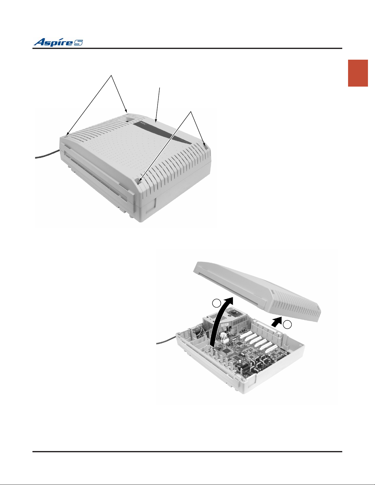
screws
Front Cover
Section 1: Installing the Cabinet
screws
0893130-1
1
Step 1
1
2
2
0893130-
Step 2
Figure 1-1: REMOVING THE FRONT COVER
Aspire S Hardware Manual Section 1: Installing the Cabinet ◆ 1-3
Page 14
Section 1: Installing the Cabinet
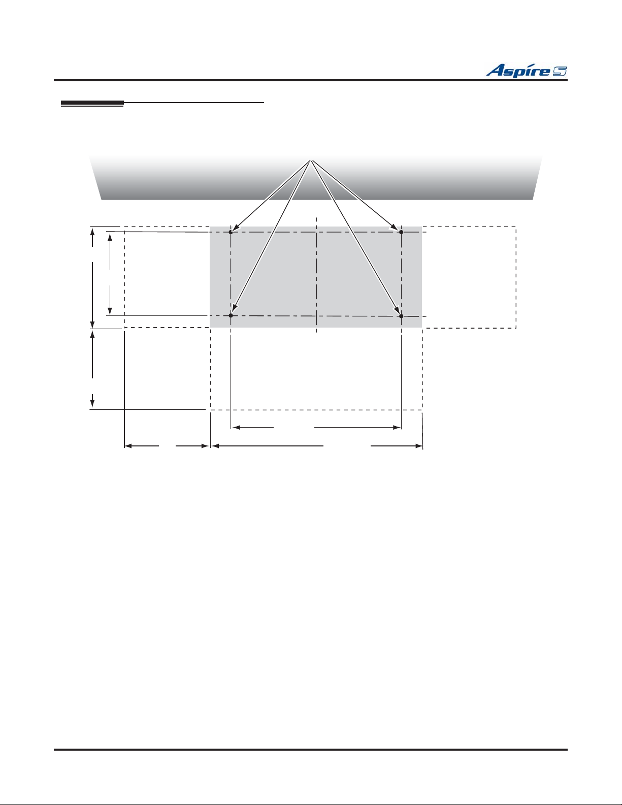
Securing the Cabinet to the Floor (Figure 1-2 - Figure 1-4)
1. Install the mounting brackets on the floor providing the appropriate spacing as shown below.
Location of anchor bolts
9 1/2"
8"
Front
12"
Wall surface
2
30 - 2
08931
Floor
11 1/2"
12"
16 7/16"
Figure 1-2: INSTALLING THE MOUNTING BRACKETS
1-4 ◆ Section 1: Installing the Cabinet Aspire S Hardware Manual
Page 15
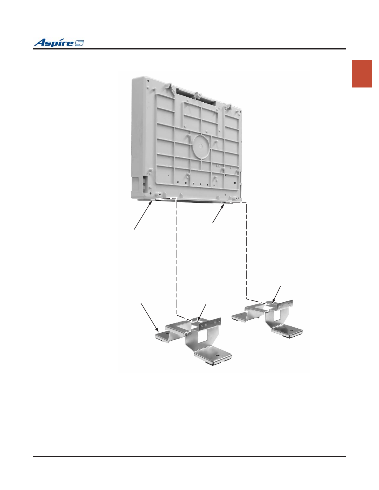
Section 1: Installing the Cabinet
2. Attach the floor mounting brackets to the cabinet. Insert the tabs of the brackets into the slots on the
bottom of the cabinet.
0893130 - 20
Cabinet
1
Bracket insertion hole
Bracket insertion hole
Ta b
Floor mount bracket
Figure 1-3: SECURE THE MOUNTING BRACKETS WITH SCREWS
Ta b
Aspire S Hardware Manual Section 1: Installing the Cabinet ◆ 1-5
Page 16
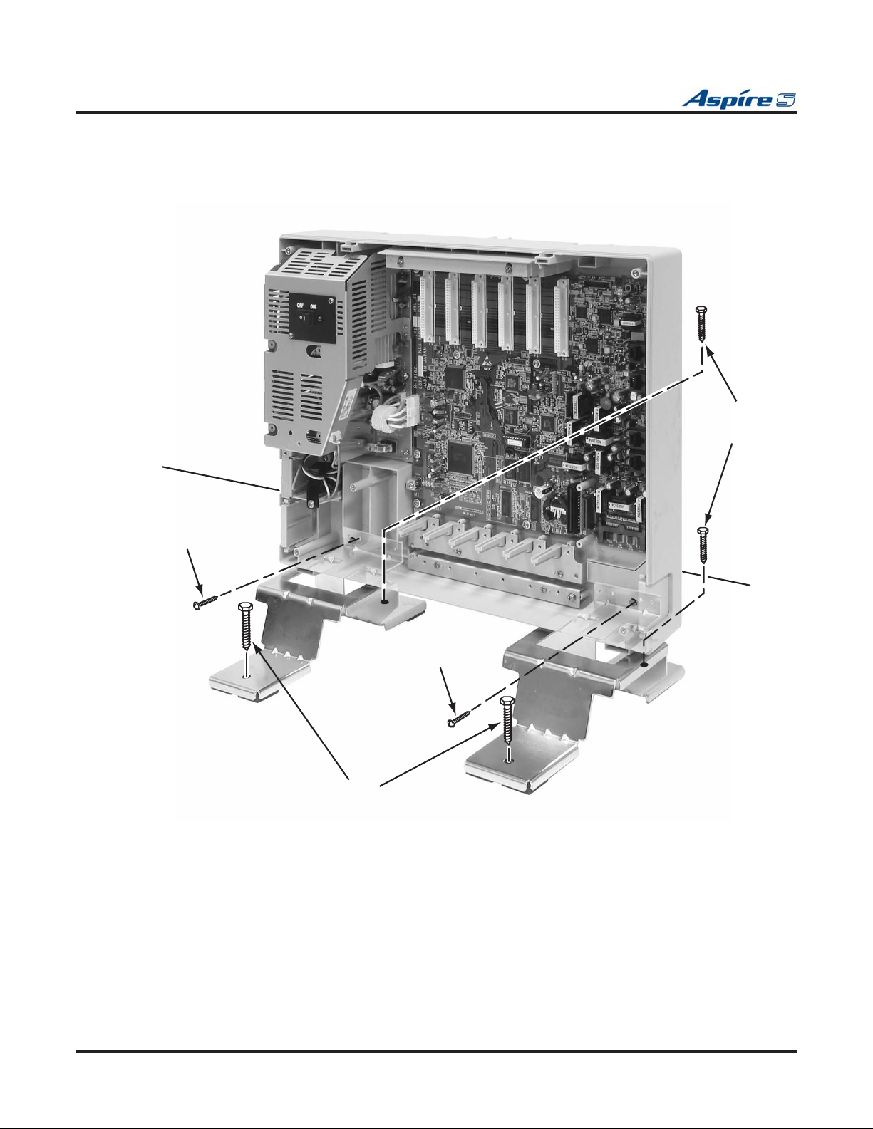
Section 1: Installing the Cabinet
3. Secure the brackets to the cabinet with the screws provided with the bracket. Then secure the
mounting brackets to the floor using 4 6mm anchor bolts.
0893130 - 21
Wall surface
6mm
Anchor
Bolt
Screw
Screw
6mm
Anchor
Bolt
Floor surface
Figure 1-4: SECURE THE MOUNTING BRACKET WITH SCREWS
1-6 ◆ Section 1: Installing the Cabinet Aspire S Hardware Manual
Page 17
Section 1: Installing the Cabinet
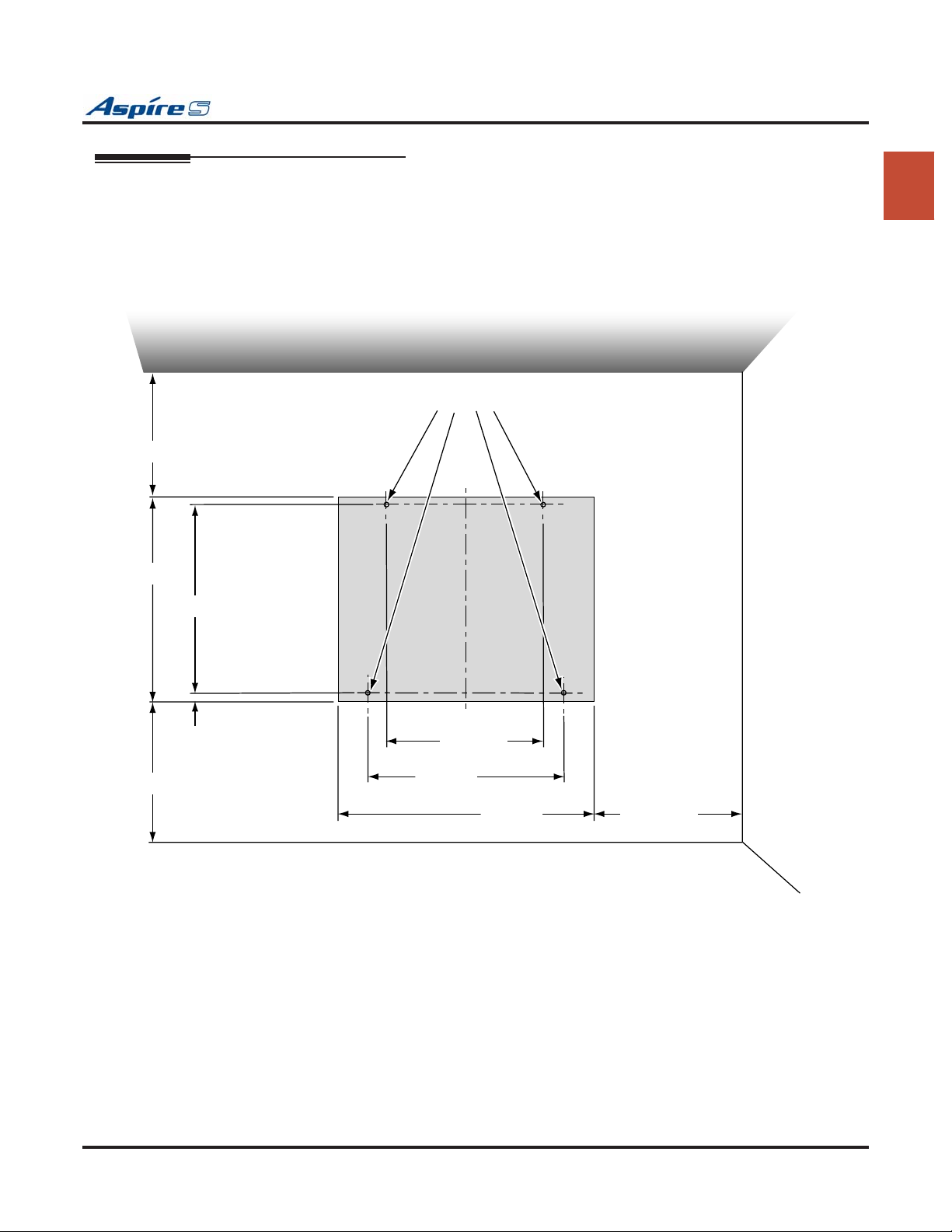
Securing the Cabinet to the Wall (Figure 1-5 - Figure 1-8)
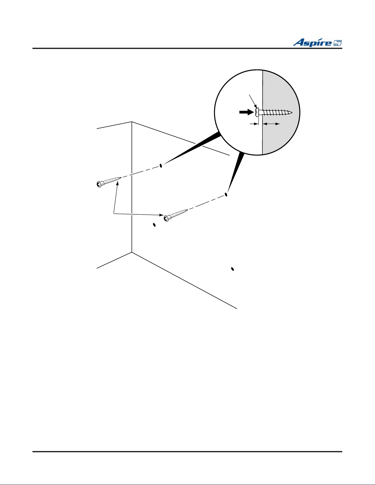
1. Install the two wood screws to the wall providing the appropriate spacing as shown below. The two
top key-hole screws should protrude from the wall about 3/16” to allow the cabinet to slide over the
screw heads.
It is suggested that plywood first be installed on the wall where the cabinet will be positioned.
This allows for secure anchoring of the screws which will be supporting the weight of the cabinet.
Ceiling
1
12" or more
13 3/16"
12" or more
12 3/16"
1/4"
Location of wood screws
10 1/16"
12 5/8"
16 7/16" 12" or more
0893130 - 13
Wall surface
Floor surface
Figure 1-5: CABINET SPACE REQUIREMENTS
Aspire S Hardware Manual Section 1: Installing the Cabinet ◆ 1-7
Page 18
Section 1: Installing the Cabinet
Wood screw
Wood screw
Gap
(approx. 3/16"
Wall
A
B
C
Wall surface
Floor surface
089313
D
0 - 14
Figure 1-6: INSTALLING THE WOOD SCREWS
1-8 ◆ Section 1: Installing the Cabinet Aspire S Hardware Manual
Page 19
Section 1: Installing the Cabinet
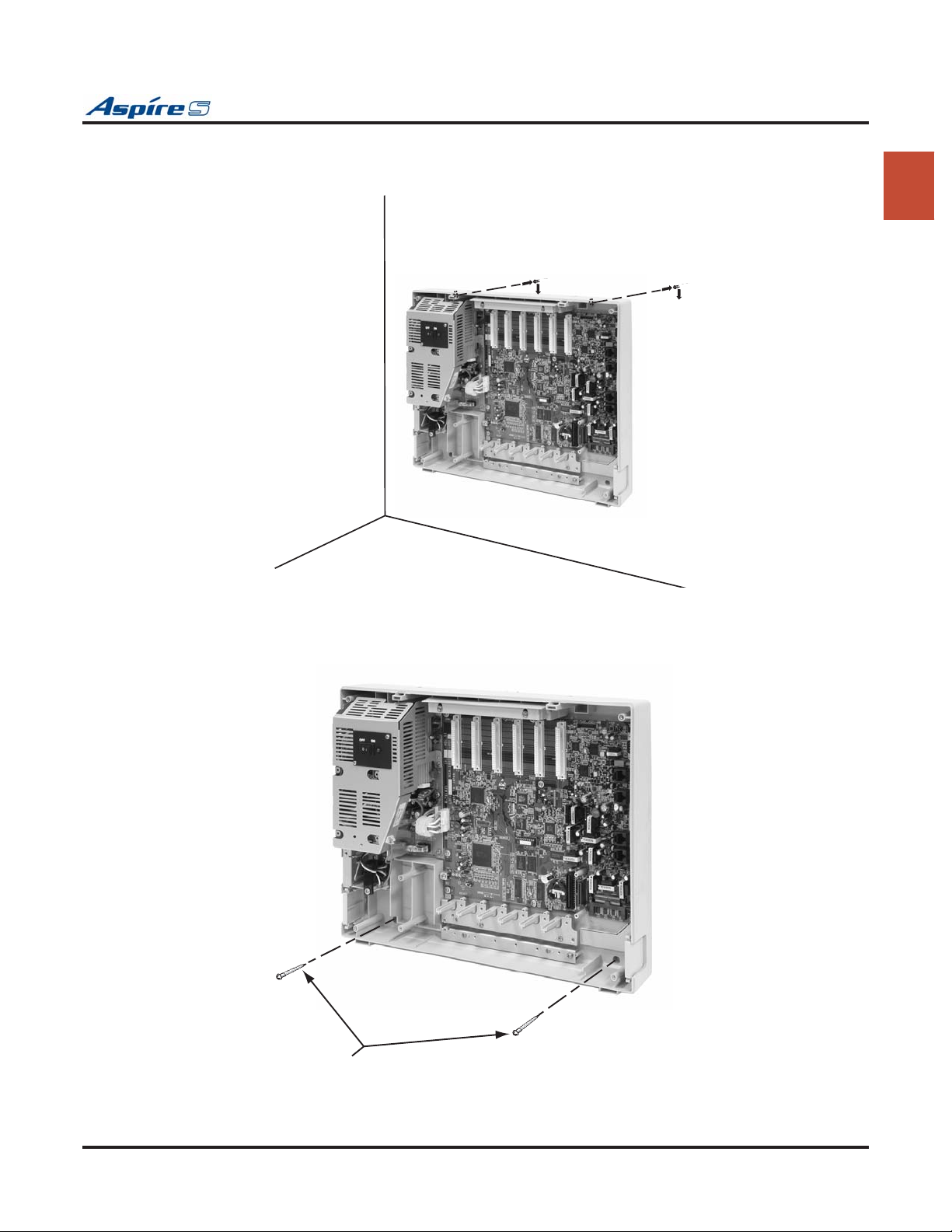
2. Lift the cabinet into position and slide the cabinet over the screws attached to the wall. Making sure
the cabinet moves down to the top of the keyhole opening.
Wall surface
0893130 - 18
Floor surface
1
Figure 1-7: PLACE THE CABINET ON THE WALL
3. Secure the cabinet to the wall by inserting the two screws into the bottom half of the cabinet.
Wall surface
0893130 - 19
2 wood screws
Figure 1-8: FASTEN CABINET TO WALL
Aspire S Hardware Manual Section 1: Installing the Cabinet ◆ 1-9
Page 20
Section 1: Installing the Cabinet
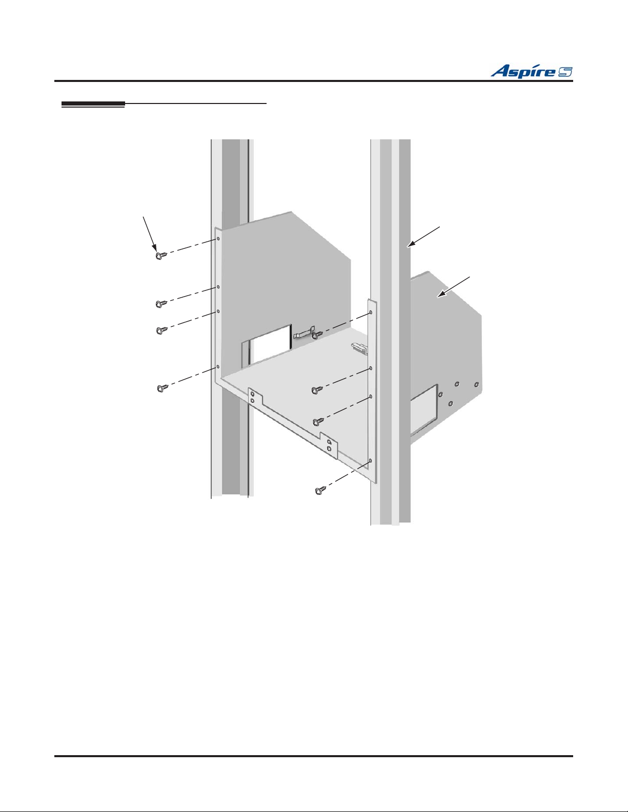
Securing the Cabinet to a Rack (Figure 1-9 - Figure 1-12)
1. Install the 19” rack mount bracket.
0893100 - 44
Screws attached
to Rack Bracket
19 inch Rack
19 inch Rack
Bracket
Figure 1-9: INSTALLING THE MOUNTING BRACKET ON THE RACK
1-10 ◆ Section 1: Installing the Cabinet Aspire S Hardware Manual
Page 21
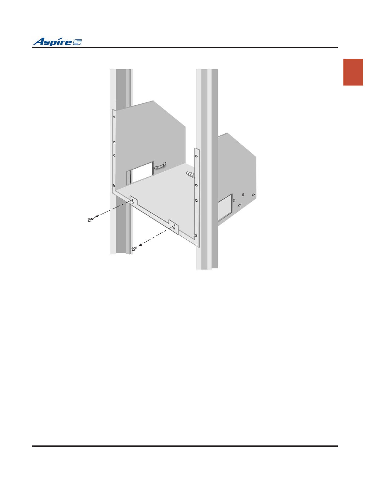
Section 1: Installing the Cabinet
2. Remove the 2 screws from the front of the rack mount bracket.
0893100 - 45
1
Figure 1-10: REMOVE THE SCREWS FROM THE RACK
Aspire S Hardware Manual Section 1: Installing the Cabinet ◆ 1-11
Page 22
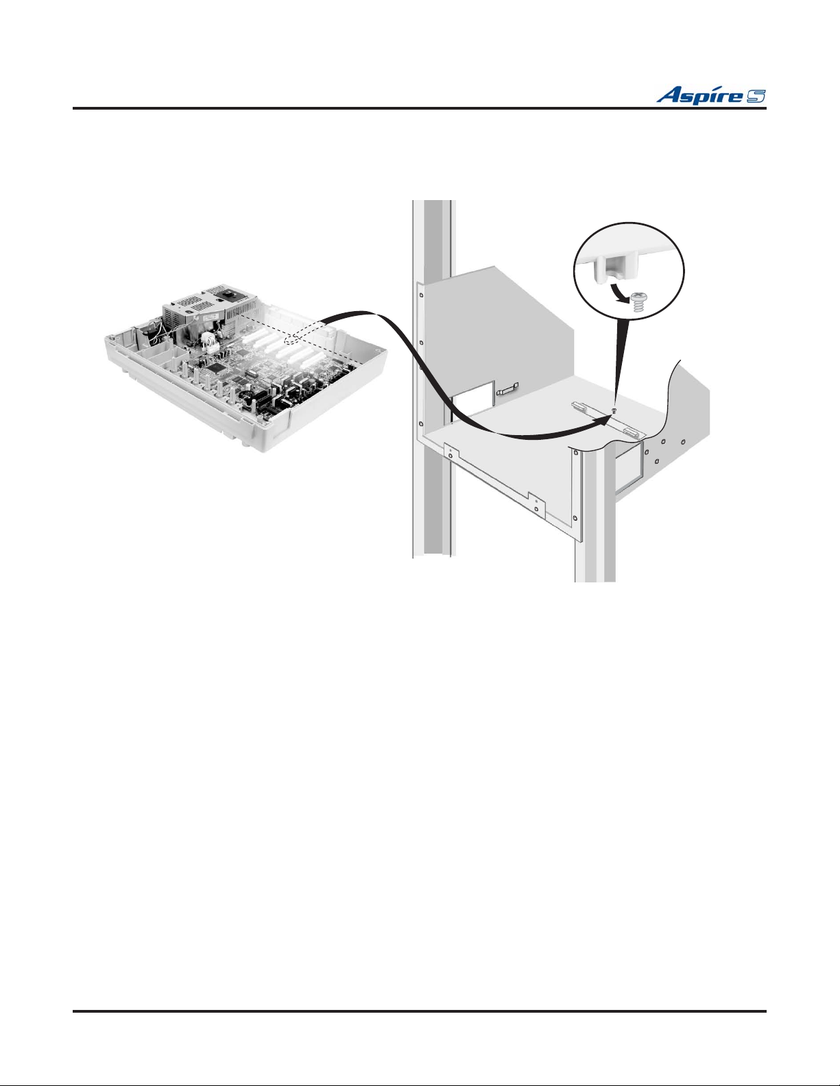
Section 1: Installing the Cabinet
3. Place the cabinet in the rack, making sure the screw on the rack’s mounting bracket catches the cabinet’s molded stop on the bottom of the cabinet. This will help secure the cabinet in place and prevent it from sliding backwards.
0893130 - 1
1
Figure 1-11: INSTALLING THE CABINET IN THE RACK
1-12 ◆ Section 1: Installing the Cabinet Aspire S Hardware Manual
Page 23
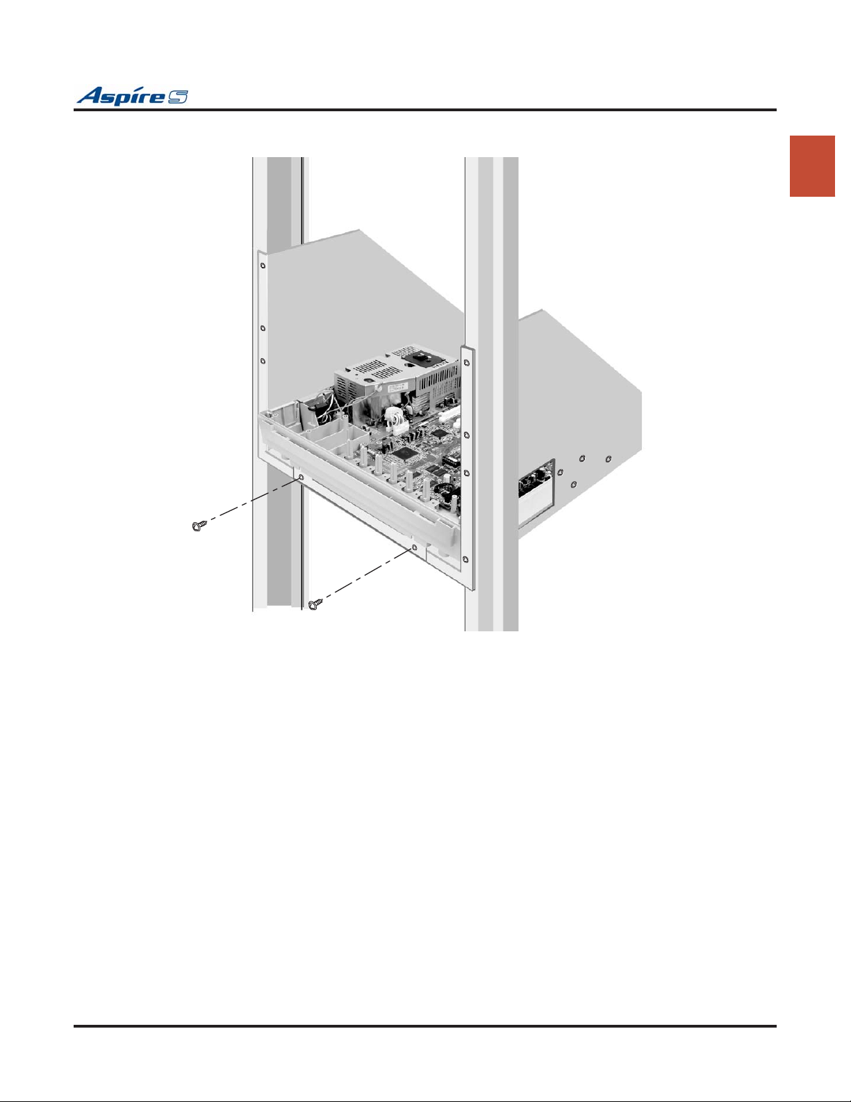
Section 1: Installing the Cabinet
4. Replace the screws in the front of the rack which were removed in step 2.
0893130 - 12
1
Figure 1-12: SECURING THE CABINET TO THE RACK
Aspire S Hardware Manual Section 1: Installing the Cabinet ◆ 1-13
Page 24
Section 1: Installing the Cabinet
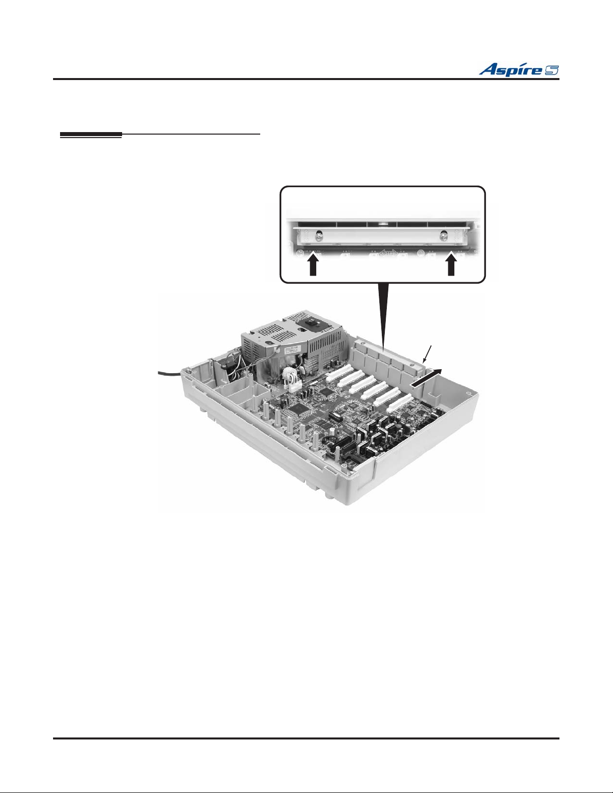
INSTALLING THE PCBS
PCB Installation (Figure 1-13 - Figure 1-16)
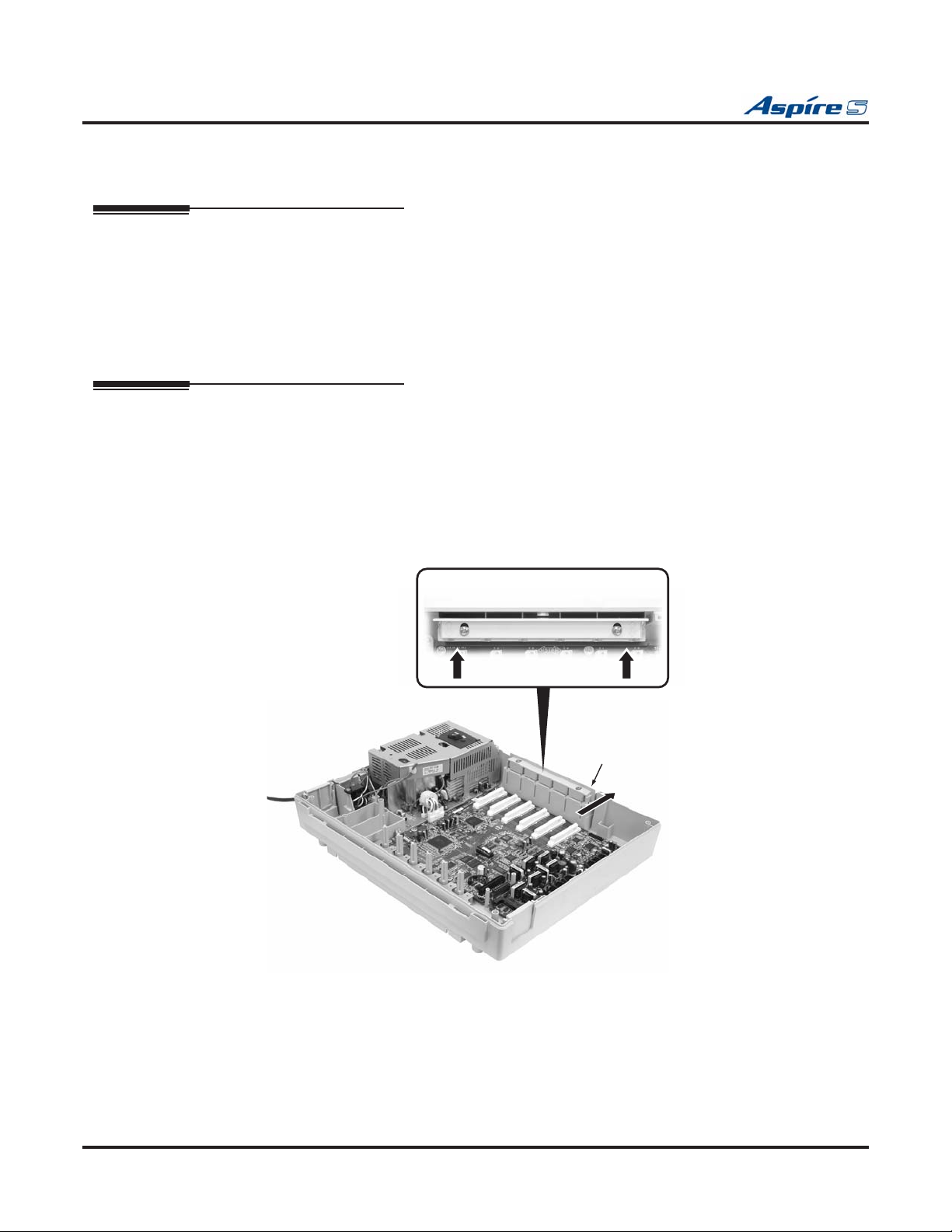
1. Slide the PCB retaining bar back until you hear it click in place.
Do not loosen the screws.
Push both ends when moving
the retaining bar.
PCB Retaining Bar
0893130-9
Figure 1-13: MOVING THE RETAINING BAR
1-14 ◆ Section 1: Installing the Cabinet Aspire S Hardware Manual
Page 25
Section 1: Installing the Cabinet
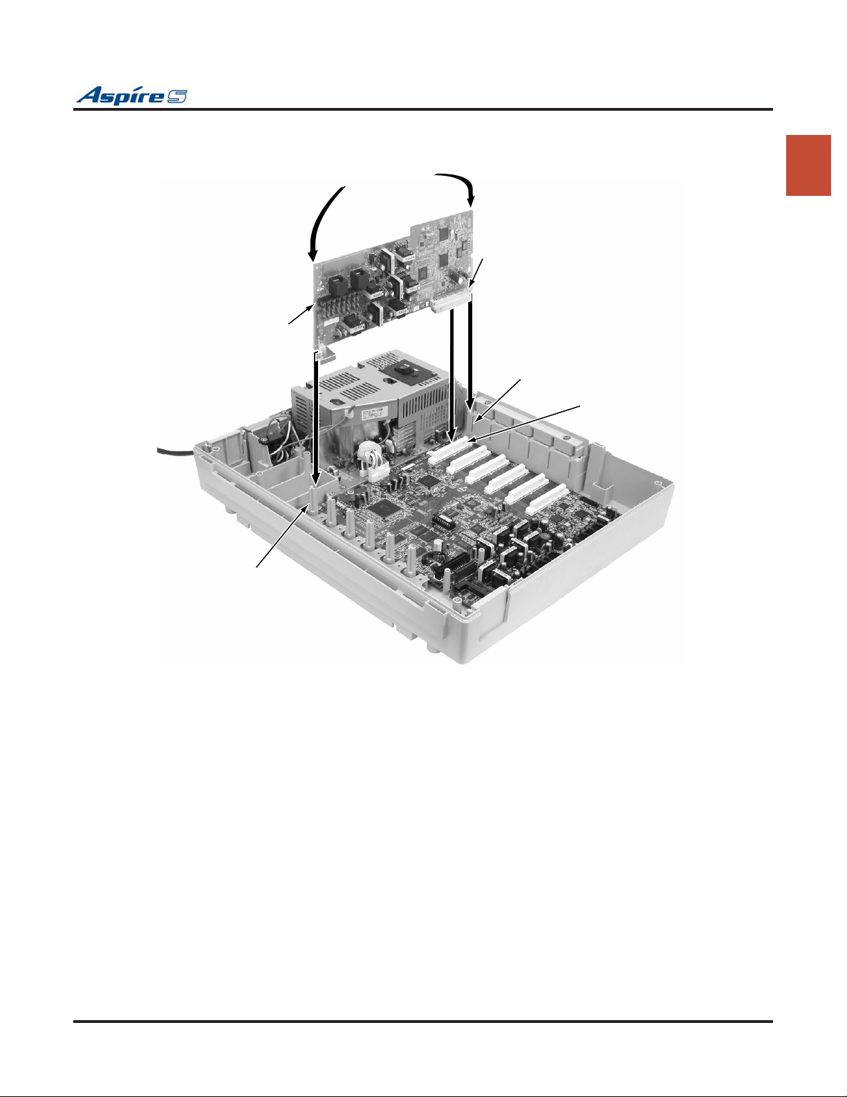
2. Insert the PCB along the guide rails and firmly plug in the PCB connector to the CPU.
PCB
Hold the corner of
both ends of unit
1
Connector
Guide rail (top)
Connector in Cabinet
(SLOT3 thru SLOT 8)
Guide rail (bottom)
0893130-10
Figure 1-14: INSERTING THE PCB
Aspire S Hardware Manual Section 1: Installing the Cabinet ◆ 1-15
Page 26
Section 1: Installing the Cabinet
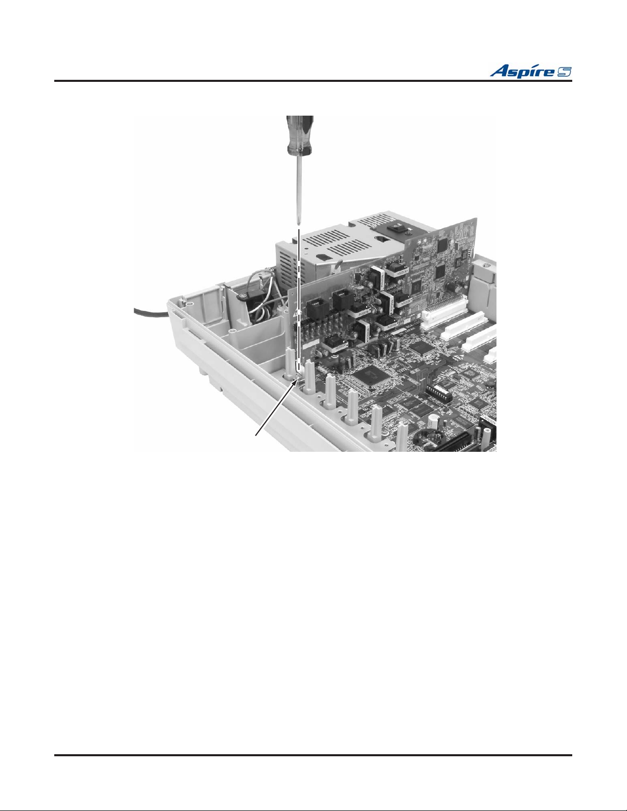
3. Secure the PCB to the CPU by attaching the screw provided on the PCB as shown below.
0893130-5
Screw
Figure 1-15: SECURING THE PCB
1-16 ◆ Section 1: Installing the Cabinet Aspire S Hardware Manual
Page 27
Section 1: Installing the Cabinet
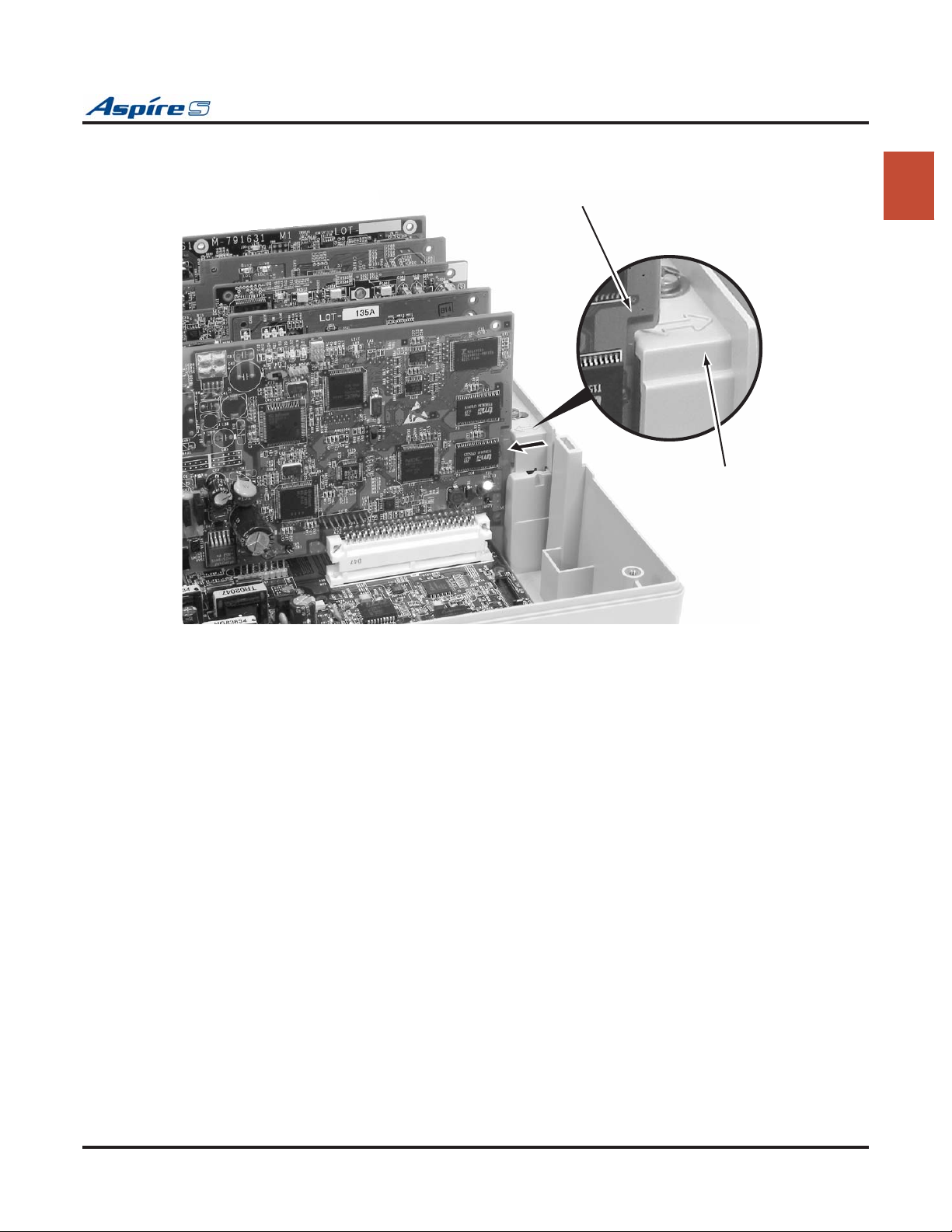
4. Move the PCB retaining bar back in place to secure to top of the PCBs.
0893130
PCB
PCB Retaining Bar
-7
Figure 1-16: MOVING THE RETAINING BAR BACK
1
Aspire S Hardware Manual Section 1: Installing the Cabinet ◆ 1-17
Page 28
Section 1: Installing the Cabinet
GROUNDING THE CABINETS
Connecting the System Ground (Figure 1-17)
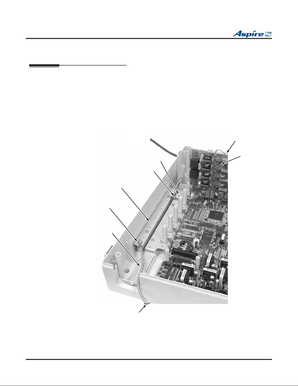
1. Ground the cabinet by connecting a 14 AWG wire from the ETH lug to a known earth ground, such
as a copper plate or grounding rod.
Be cautious when using a cold water pipe that it’s completely copper and does not change to
PVC/vinyl chloride pipe.
2. When installing a COIU or DIOPU PCB, connect the grounding wire of the PCB to the PBXG terminal plate and then run a grounding wiring from the PBXG terminal plate to a known earth ground
using 14 AWG grounding wire.
The ETH and PBXG grounds should be separate - they should not be combined.
3. From the factory, the FG is already connected to the AC power source. No action is required.
Frame Ground
PBXG Terminal Plate
Grounding Wire
Connection Terminal
Grounding Wire
Earth Ground
PBXG Connection
Cable
PCB
0893130-8
To Known Earth Ground
Figure 1-17: GROUNDING THE CABINET
1-18 ◆ Section 1: Installing the Cabinet Aspire S Hardware Manual
Page 29

Section 1: Installing the Cabinet
The ground lug descriptions are as follows:
● PBXG (CO/PBX Ground)
The grounding wire from the COIU or DIOPU PCBs are connected to the PBXG terminal plate. A
grounding wire should then be connected from the PBXG terminal plate to a known earth ground when
these PCBs are installed in the system.
This grounding wire should be separate from the ETH grounding wire.
● ETH (Earth Ground)
This ground lug is used for lightning protection. It should always be connected to the earth.
This grounding wire should be separate from the PBXG grounding wire.
● FG (Frame Ground)
This ground lug is connected from the power supply cable to the metal frame of the main equipment.
1
Aspire S Hardware Manual Section 1: Installing the Cabinet ◆ 1-19
Page 30
Section 1: Installing the Cabinet
COMPLETING THE INSTALLATION
Setting the Cable Pass-Through (Figure 1-18 - Figure 1-20)
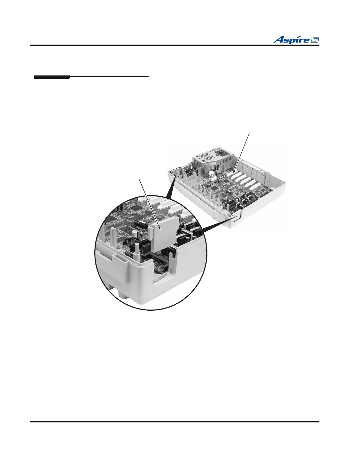
The each cabinet has two cable pass-throughs - one each on the left and right sides of the cabinet. The block
plate should be in place for any unused pass-through in order to help keep dust out of the cabinet.
1. There are two opening options - one setting provides a small pass-through, the other provides a
larger pass-through. Determine which type is required for the cabinet.
Block Plate
Cabinet
0893130-15
Figure 1-18: CABLE PASS-THROUGH
1-20 ◆ Section 1: Installing the Cabinet Aspire S Hardware Manual
Page 31
0893130 - 16
Section 1: Installing the Cabinet
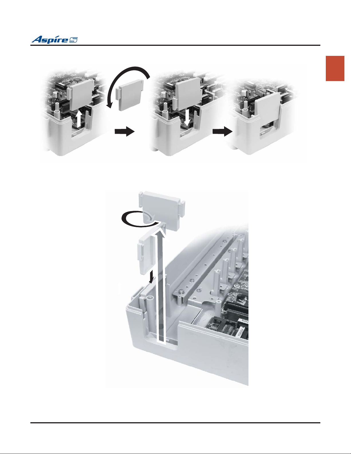
2. For the small pass-through, turn the block plate upside down and replace into the slot.
1
Figure 1-19: SMALL CABLE PASS-THROUGH
3. For the large pass-through, remove the block plate and store it in the bottom-right corner of the cabinet.
0893130 - 17
Figure 1-20: LARGE CABLE PASS-THROUGH
Aspire S Hardware Manual Section 1: Installing the Cabinet ◆ 1-21
Page 32
Section 1: Installing the Cabinet
Reinstalling the Front Cover (Figure 1-21 - Figure 1-22)
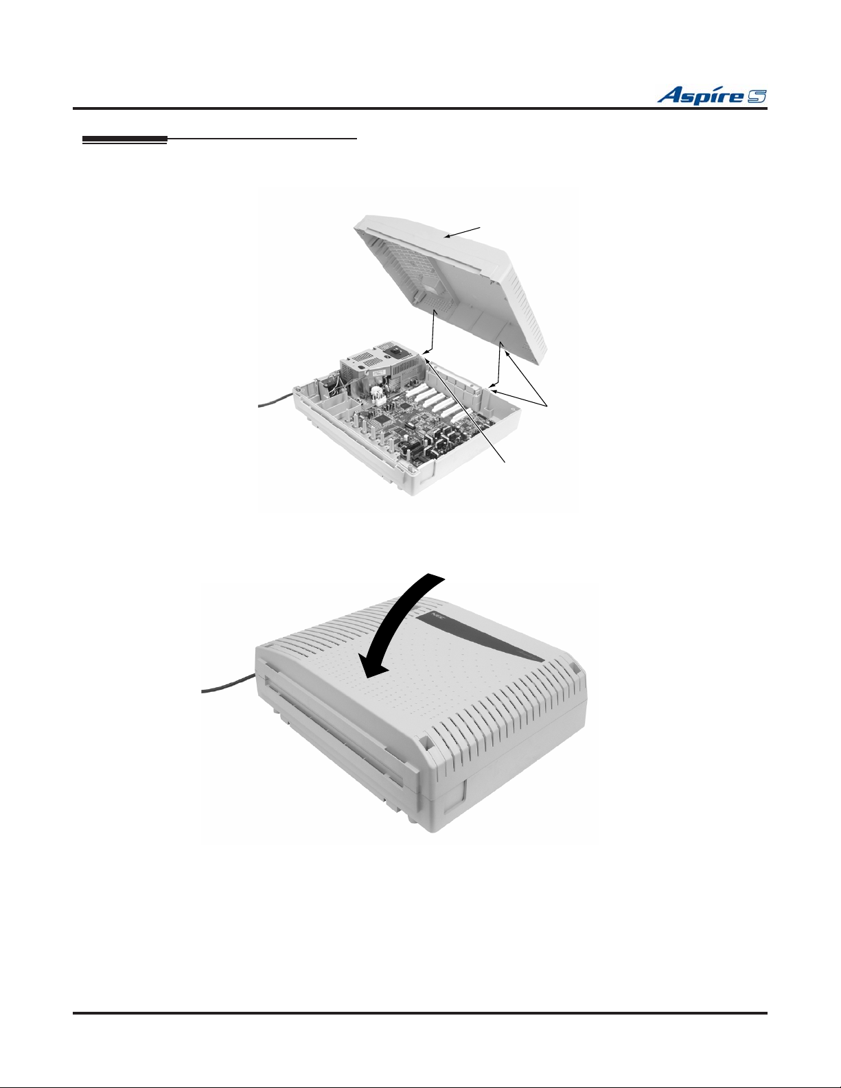
1. Line up the hooks on the front cover with the slots in the cabinet and insert the cover.
Front Cover
0893130
Hook
Hook
-3
Figure 1-21: RE-INSTALLING THE FRONT COVER
2. Lower the cover.
4
0893130-
Figure 1-22: LOWER THE FRONT COVER
3. Tighten the four cover retaining screws.
A label is located on the right side of the cabinet which can be used to enter the date when the
battery should be replaced. In case of a power failure, this battery provides back-up of system data
and RAM memory for approximately 30 months. Program 90-11-01 can also be set to define an
extension to receive an indication on their display when the battery is low.
1-22 ◆ Section 1: Installing the Cabinet Aspire S Hardware Manual
Page 33
PCB Installation and Startup
Section 2: PCB Installation and Startup
PCB LAYOUT
Section 2: PCB Installation and Startup
Section 2:
2
PCB Location
Determine the slot position for each PCB. In the cabinet:
● Slots 3 - 8 are universal (any type of PCB can be installed). The only restriction is that an ESIU PCB
• Make sure to follow the steps indicated in Powering Up the System (page 2-40) for an initial
• To delete a PCB from the system, power down the system and then remove the PCB from the sys-
• Whenever powering down the system, check to make sure the only LED flashing on the CPU
can not be placed into slots 7 or 8 as there are not enough conversation channels.
Important Notes
system install. This will ensure that you start the system with the default system settings.
tem cabinet. Power the system back up and use Program 90-05-01 to delete the slot definition.
card itself (in the lower left-hand corner) is the LD2 LED (the LED located farthest right in the
line of LEDs). This LED is located in the lower left-hand corner of the CPU. It should be flash-
ing 0.5 seconds on/off (a slow flash). If it’s flashing fast or if any other LEDS are flashing on the
CPU, wait until they stop or else the system data may be corrupted.
After turning the power on, the user must wait approximately 10 seconds (so that only the LD2
LED is flashing) if the system must be powered down again.
Aspire S Hardware Manual Section 2: PCB Installation and Startup ◆ 2-1
Page 34
Section 2: PCB Installation and Startup
PCB INSTALLATION
Handling the PCBs
The PCBs are sensitive to static discharge. To minimize static discharge, keep PCBs in static free bags when
not installed. Observe the following when installing or removing a PCB:
● Ground the cabinet.
● Wear a grounded wrist strap to install/remove any PCBs.
● Do not touch PCB components. Handle the PCBs in the corners.
● All PCBs must be installed with the system power off.
Installing an Extension or Trunk PCB (Figure 2-2)
To install an extension/trunk PCB:
● Power down the system.
Whenever powering down the system, check to make sure the only LED flashing on the CPU
card itself is the LD2 LED (farthest right of the LEDs). This LED is located in the lower left-hand
corner of the CPU. If any other LEDS are flashing on the CPU, wait until they stop or else the system data may be corrupted.
● Push the retaining bar up (or back depending on the cabinet’s position).
Push both ends when moving
the retaining bar.
PCB Retaining Bar
0893130-9
Figure 2-1: MOVING THE RETAINING BAR
2-2 ◆ Section 2: PCB Installation and Startup Aspire S Hardware Manual
Page 35
Section 2: PCB Installation and Startup
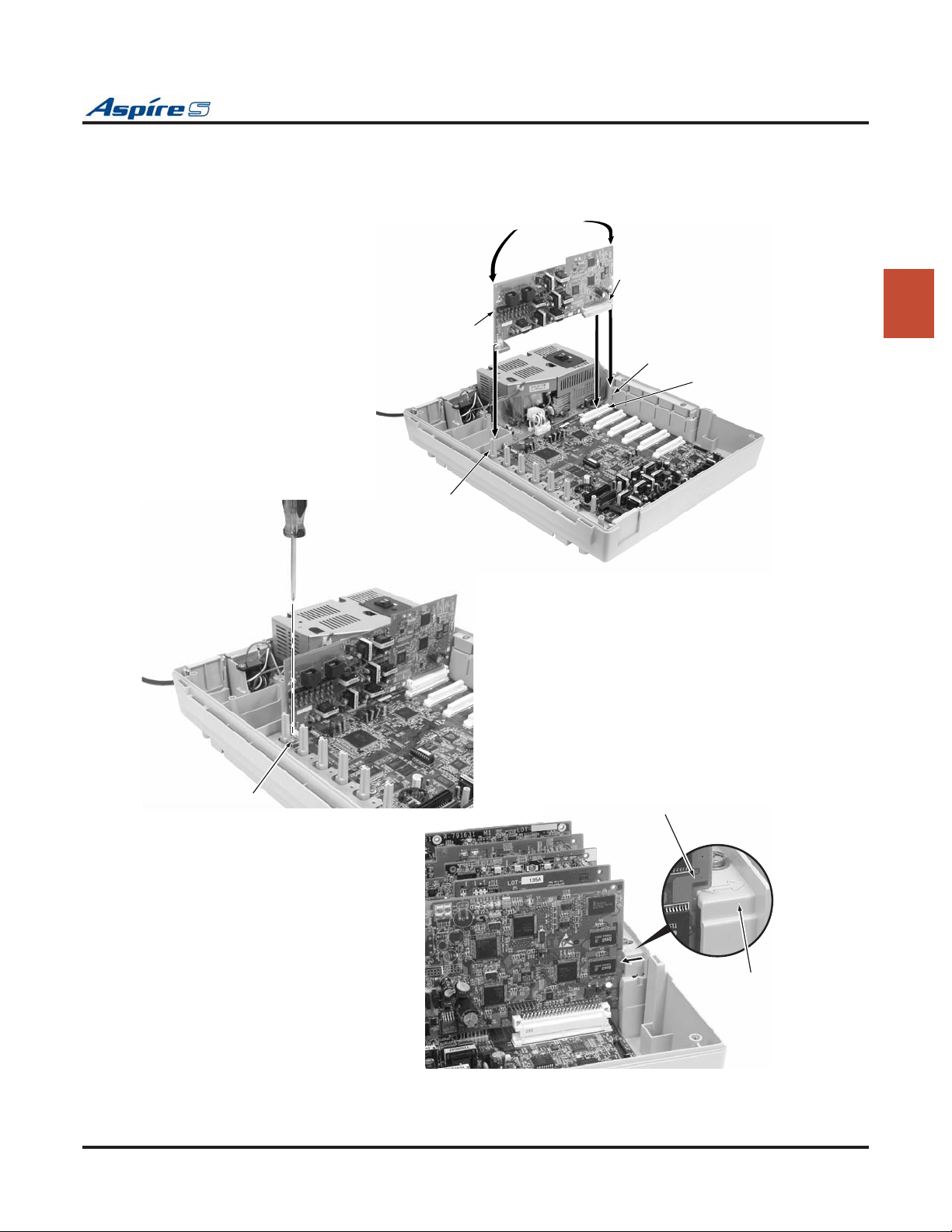
● Insert the PCB within the guide rail and push the PCB securely into position. After installing all the
PCBs, the PCB retaining bar should be moved back into position and the screws for each of the PCBs
should be tightened.
Hold the corner of
both ends of unit
Connector
Guide rail (bottom)
PCB
0893130-5
Guide rail (top)
0893130-10
Connector in Cabinet
(SLOT3 thru SLOT 8)
2
Screw
0893130
-7
PCB
PCB Retaining Bar
Figure 2-2: INSERTING PCBS
Aspire S Hardware Manual Section 2: PCB Installation and Startup ◆ 2-3
Page 36

Section 2: PCB Installation and Startup
Removing an Extension or Trunk PCB
Whenever powering down the system, check to make sure the only LED flashing on the CPU card itself is the
LD2 LED (farthest right). This LED is located in the lower left-hand corner of the CPU. If any other LEDS
are flashing on the CPU, wait until they stop or else the system data may be corrupted.
To remove an extension/trunk PCB:
● Turn off the system power by pressing the ON/OFF switch on the cabinet.
Whenever powering down the system, check to make sure the only LED flashing on the CPU
card itself is the LD2 LED (farthest right of the LEDs). This LED is located in the lower left-hand
corner of the CPU. If any other LEDS are flashing on the CPU, wait until they stop or else the system data may be corrupted.
● All PCBs must be installed with the system power off.
Uninstalling a PCB Slot Through Software
The installer can turn off (busy out) and delete (remove from software) PCB slots in the cabinet in programming for port re-numbering purposes or to replace it with a different type of PCB. Deleting a PCB may
affect PCB slot programming capability. Refer to Program 90-05 in the Software Manual for further details.
2-4 ◆ Section 2: PCB Installation and Startup Aspire S Hardware Manual
Page 37
Where to Install the PCBs
Section 2: PCB Installation and Startup
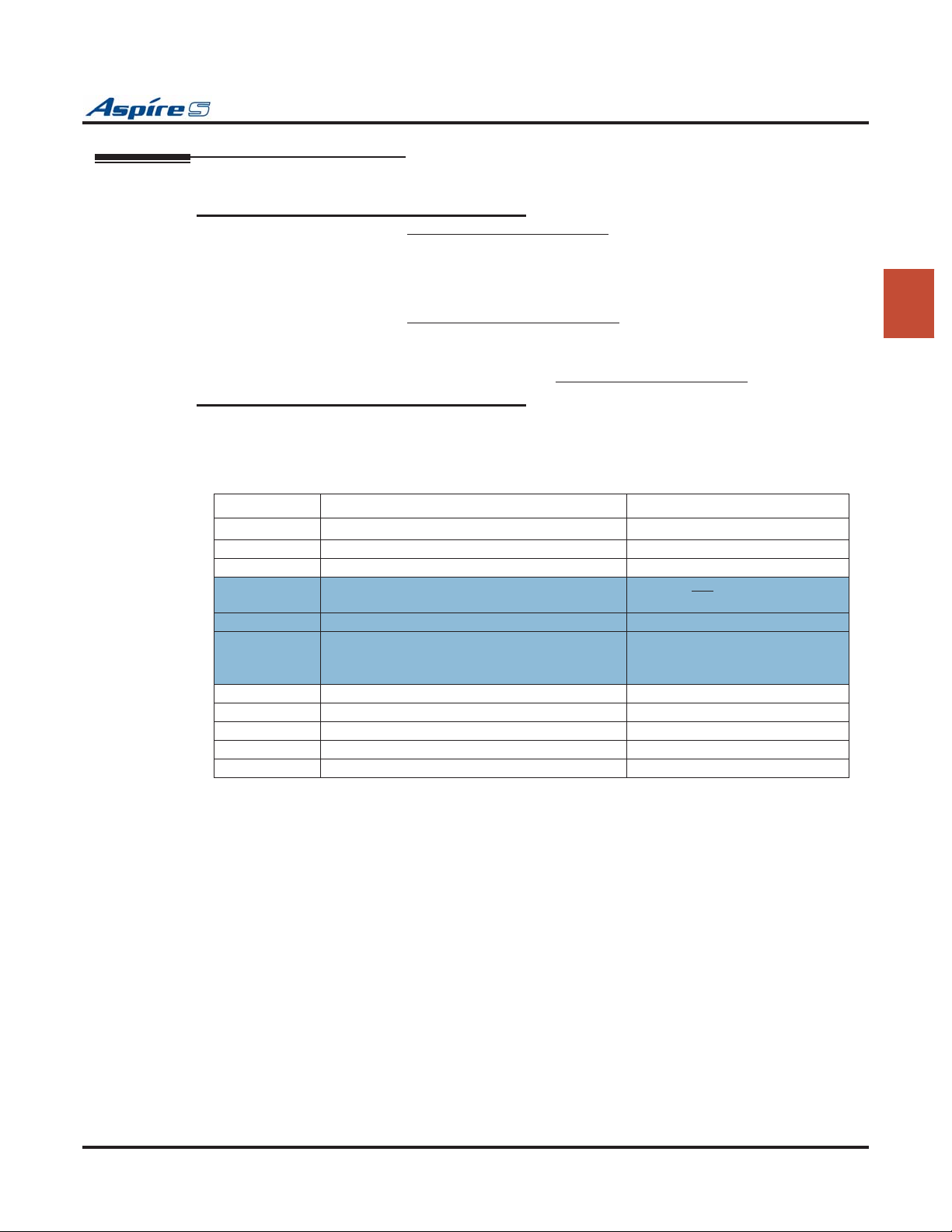
Maximum Configuration: With Software 2.08-2.21 Only
The system’s universal architecture gives you great flexibility when installing PCBs. You can install a PCB
in any slot, provided you follow the guidelines in the chart below.
Item Description Max.
CPU (MBU) 32-Bit Central Processing Unit
DSPDB DSP Resource - Daughter Board 1 installed on CPU
ENTU-S LAN CTI Ethernet Interface Board 1 installed on CPU
8ESIU-S 8 Digital Stations 2 - Can not be installed in slots
4SLIU-S 4 Analog Stations 4
4SLIDB-S 4 Analog Stations - Daughter Board 0 - If 4 4SLIU PCBs installed
4COIU-S 4 Analog/Loop Start Trunks (no ground start) 2
2BRIU-S 2 Two-Channel BRI Circuits 2 - When used as T-Point
2DIOPU-S 2 DID/OPX Trunks 4
4VOIPU-S 4 VoIP Media Gateway 3
4VOIPDB-S 4 VoIP Media Gateway - Daughter Board 3
8 Trunks
26 Extensions (24 digital and analog, 2 analog only)
- Includes a maximum of 16 IP Extensions
24 Virtual Extensions
With Software 2.50 and Higher
8 Trunks
26 Extensions (24 digital and analog, 2 analog only)
16 IP Extensions or APR-B2 Extensions
8 Special Terminals - Reserved for Intramail Only (ports 43-50)
24 Virtual Extensions
1
7 or 8
1 - If 3 4SLIU PCBs installed
2 - If 2 4SLIU PCBs installed
2
Aspire S Hardware Manual Section 2: PCB Installation and Startup ◆ 2-5
Page 38

Section 2: PCB Installation and Startup
Central Processing Unit (CPU) PCB (Figure 2-3)
The CPU, which is pre-installed, controls all the functions and operations of the Aspire system using the
system software loaded into the CPU memory. One 32-bit CPU is installed in the system cabinet.
The CPU provides the following:
● Accomodates up to 34 ports (8 trunks x 26 extensions)
● 8 digital station connections
A 2PGDAD module cannot be connected to port 1 or port 2.
● 2 analog station connections (no Message Wait lamping)
● 4 diagnostic LEDs which indicate the status of various system functions
During normal operation, the “LD2” LED will be flashing. The remaining LEDs can flash on or
off depending on the current system operation.
● Time Switch (383 ch)
● Digital Phase Locked Loop (DPLL): digital phase synchronization loop
● SFLM Generation
● DSP (Digital Signal Processor: provides C-Channel control
● Tone Generation
● DTMF Tone Sender/Receiver
● System Tone Sender
● MFC Tone Sender
● MF Signal Sender (Sends caller information to CO for E911)
● Call Progress Tone Detector
● C-Channel Control
● Time Switch control
● HDLC (High-Level Data Link Control) Packet Proceessing
● Conference; 32 Channels
● Caller ID Receiver/Generation; 16 Channels
● A load button which is used for initial system startup or when upgrading system software
● One Serial Port (requires null modem/cross-over cable)
● One Compact Flash Card Slot
● One Audio Input Terminal (external MOH/BGM source)
● General Purpose Control Terminal
● Hold Tone Transmit
● IP
● Real Time Clock (tolerance 30 seconds/month)
● Internal MOH Generation
● One Connector for PAL EPROM
● One lithium battery (Sony CR2032 or equivalent) which provides battery back-up of
system data and RAM memory for approximately 30 months
● TAPI 1.x / TAPI 2 Support
2-6 ◆ Section 2: PCB Installation and Startup Aspire S Hardware Manual
Page 39
Section 2: PCB Installation and Startup
! IMPORTANT !
While the system is powered up, data may be written to the S-RAM or flash memory at any time. Before powering down the system, verify that of the 4 LEDs in the lower left corner of the CPU, only LD2 is flashing. This
LED is the farthest right of the LEDs. It should be flashing 0.5 seconds on/off (a slow flash). If it’s flashing fast
or if any other LEDS are flashing on the CPU, wait until they stop or else the system data may be corrupted.
Turning off the power when other LEDs are flashing may corrupt the flash or S-RAM data. If the flash memory
becomes corrupted, the system may not come up. If the S-RAM data is corrupted, the telephones may have
erratic operation.
When powering the system up or down, wait 10 seconds before pressing the button again. This allows the system to complete the startup/shutdown process.
2
0893130-23
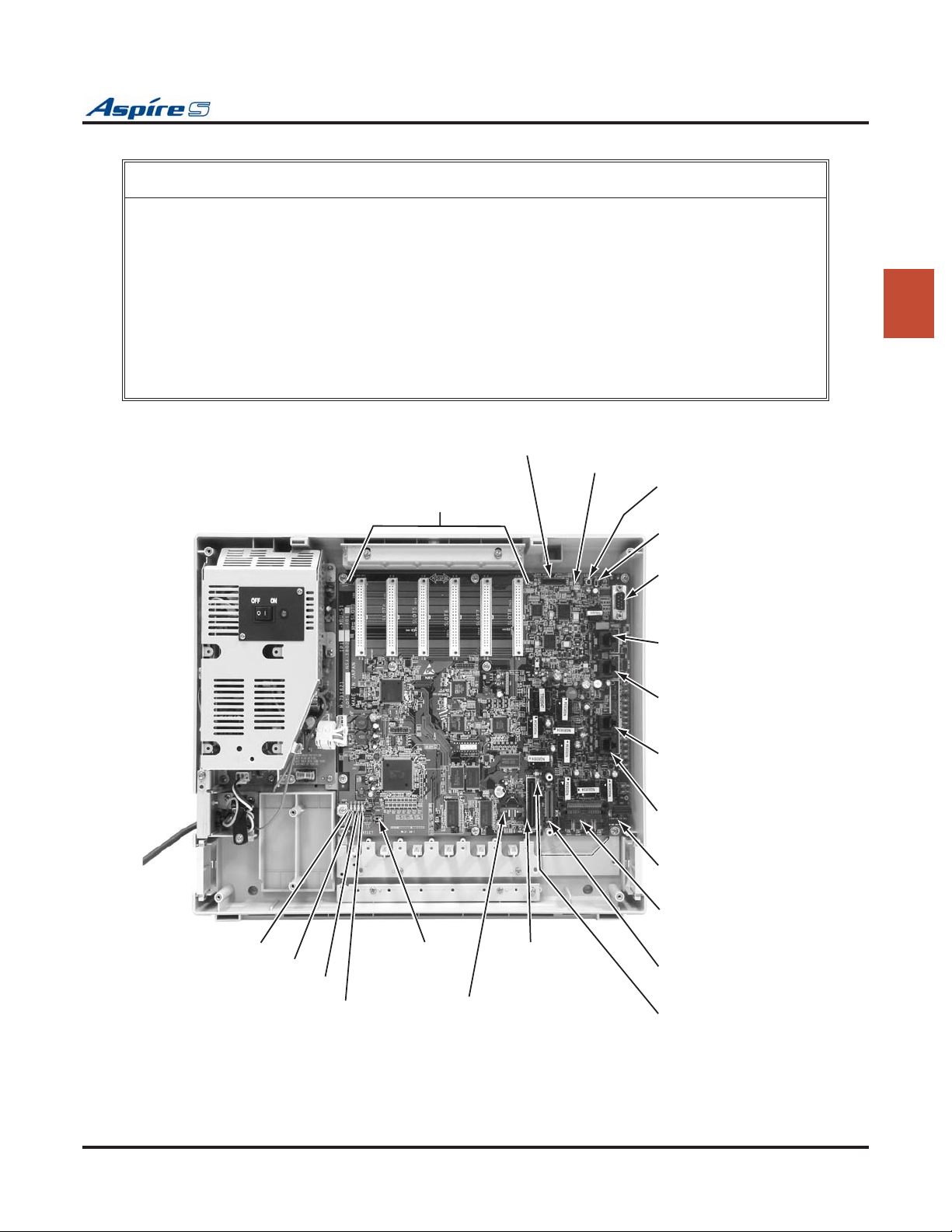
DSPDB Connector
Slots 3-8
CN4
LD6, LD7
SW1
Load Button
SW3
Serial Port Switch
CN1
Serial Cable
Connector
(D-Sub 9-pin male)
CN23
Audio In (BGM/MOH)
and General Purpose Relay
CN22
Connector for analog
terminals (SLI1,SLI2)
CN21
Connector for digital
phones (ESI5 - ESI8)
CN20
Connector for digital
phones (ESI1 - ESI4)
CN7
ENTU Connector
CN5
Compact Flash Card
LD1
LD3
LD4
Update Switch
LD2
SW4
Boot Code
(CR2032 3.0V)
CN30
ROM Board
Connector
BT1
Battery
Connector
CN6
ENTU Connector
LD5
Compact Flash Card
LED
Figure 2-3: CPU
Aspire S Hardware Manual Section 2: PCB Installation and Startup ◆ 2-7
Page 40
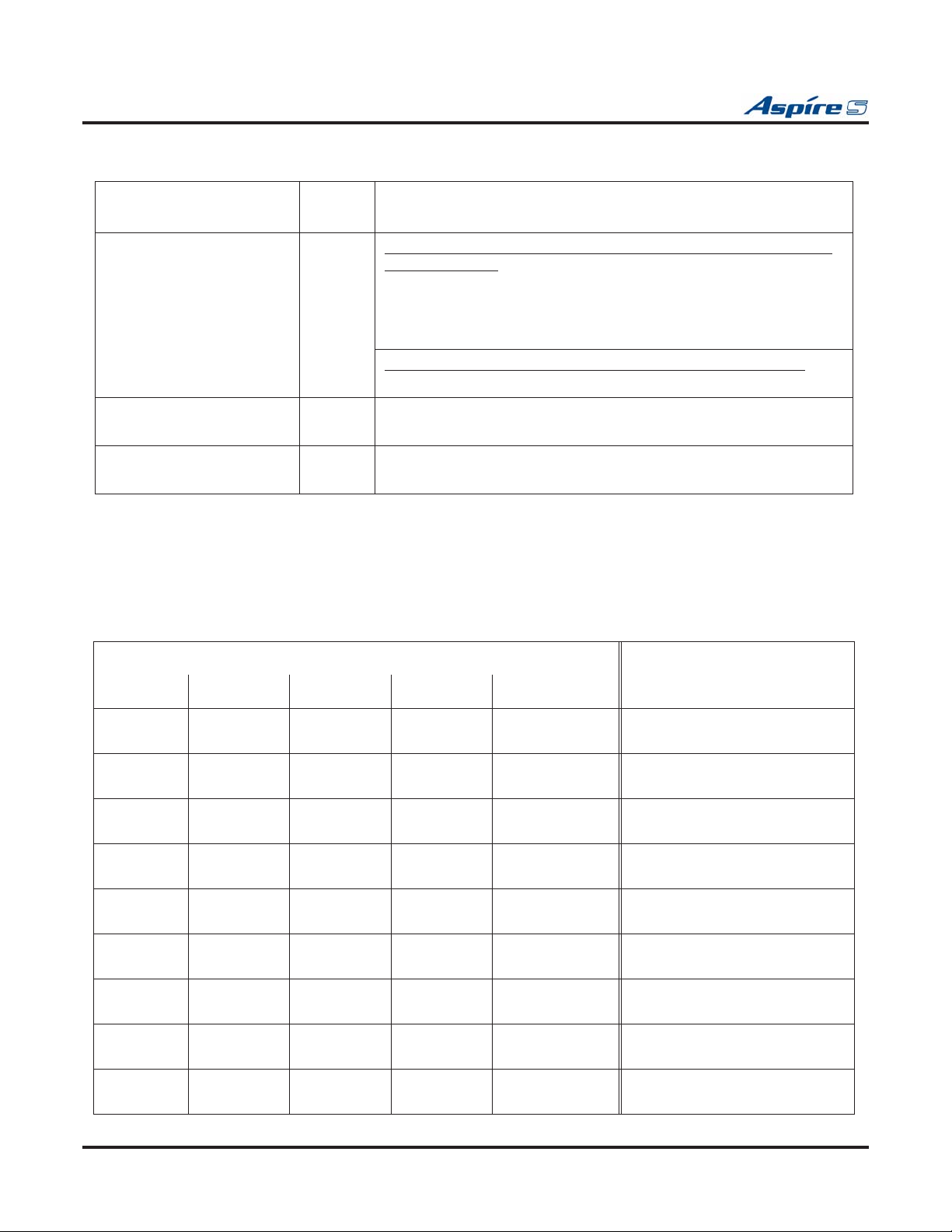
Section 2: PCB Installation and Startup
Switch Settings and LED Indications
Switch
Switch
Setting
Operation
SW1 - Load Switch - While powering up the system and holding the SW1 switch (SW3-2
switch set to off):
• With a PC-ATA: System software is updated.
• Without a PC-ATA: System boots loading stored software.
• With a Card Other Than a PC-ATA: The card is ignored and the system boots loading stored software.
While po
wering up the system without holding the SW1 switch:
• The system boots loading software stored in flash memory.
SW3 3
1
SW4 3
1
Debugging Mode (CN1 connector used for debugging)
Normal Mode (CN1 connector used for serial interface)
(Factory Use) Used to initially load system software
Normal Mode
The LED indications on the CPU represent the following:
● RUN (LD2) = Indicates the CPU is operating
● LED 1 (LD1), 3 (LD3) and 4 (LD4) = Indicate system alarms
● LED 5 (LD5) = Status of Compact Flash Card (off with no flash card installed)
● LED 6 (LD6) and 7 (LD7) = Indicates the status of single line ports 1 and 2 (off when on-hook)
Refer to Program 90-10 : System Alarm Setup for details on assigning alarm LEDs.
LED Indication
RUN (LD2) LED1 LED3 LED4 LED5
On Off Off Off On Steady with
card installed
Off Off Off Off On Steady with
card installed
Off On Off Access Blink On Steady with
card installed
Off Off On On On Steady with
card installed
Off On On Access Blink On Steady with
card installed
On Blinking Blinking Blinking On Steady with
card installed
On Blinking Off Off On Steady with
card installed
On Blinking Blinking Off On Steady with
card installed
Blinking Off Off Off On Steady with
card installed
Status
System starting up
System initializing
Initializing or formatting the disk
Boot program is initializing in the
flash memory
Loading system software
Completing system program
update
Completing boot software update
Completing disk formatting
(SRAM, Flash)
DRAM error
2-8 ◆ Section 2: PCB Installation and Startup Aspire S Hardware Manual
Page 41
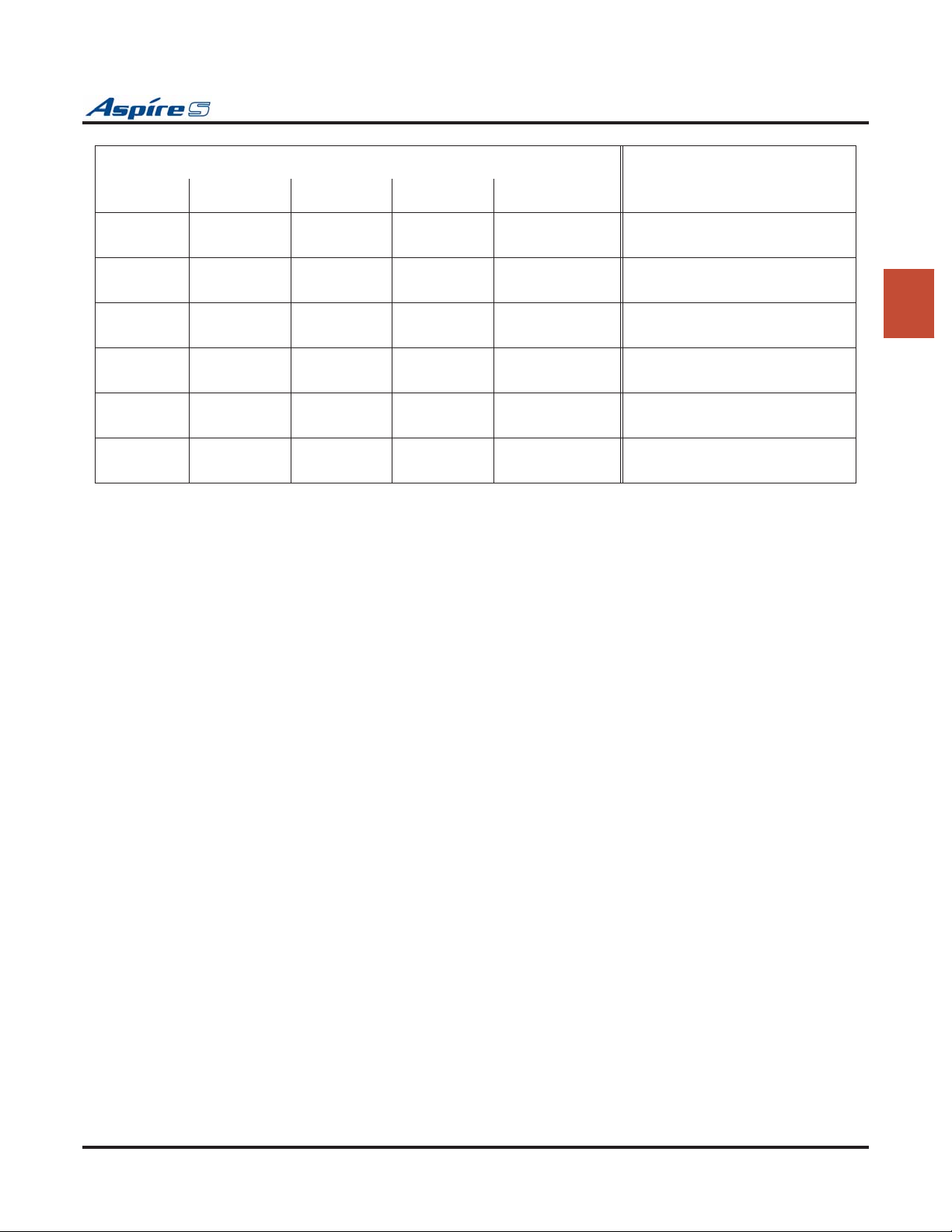
Section 2: PCB Installation and Startup
LED Indication
RUN (LD2) LED1 LED3 LED4 LED5
Status
Blinking Off Off On On Steady with
card installed
Blinking Off On Off On Steady with
card installed
Blinking Off On On On Steady with
card installed
Blinking On On On On Steady with
card installed
Blinking Blinking Blinking Blinking On Steady with
card installed
Blinking Off Off Off On Steady with
card installed
FPGA version error
SRAM error
Flash memory booting (start-up)
error
Flash memory data error
Read error of system program
Running normally
2
Aspire S Hardware Manual Section 2: PCB Installation and Startup ◆ 2-9
Page 42
Section 2: PCB Installation and Startup
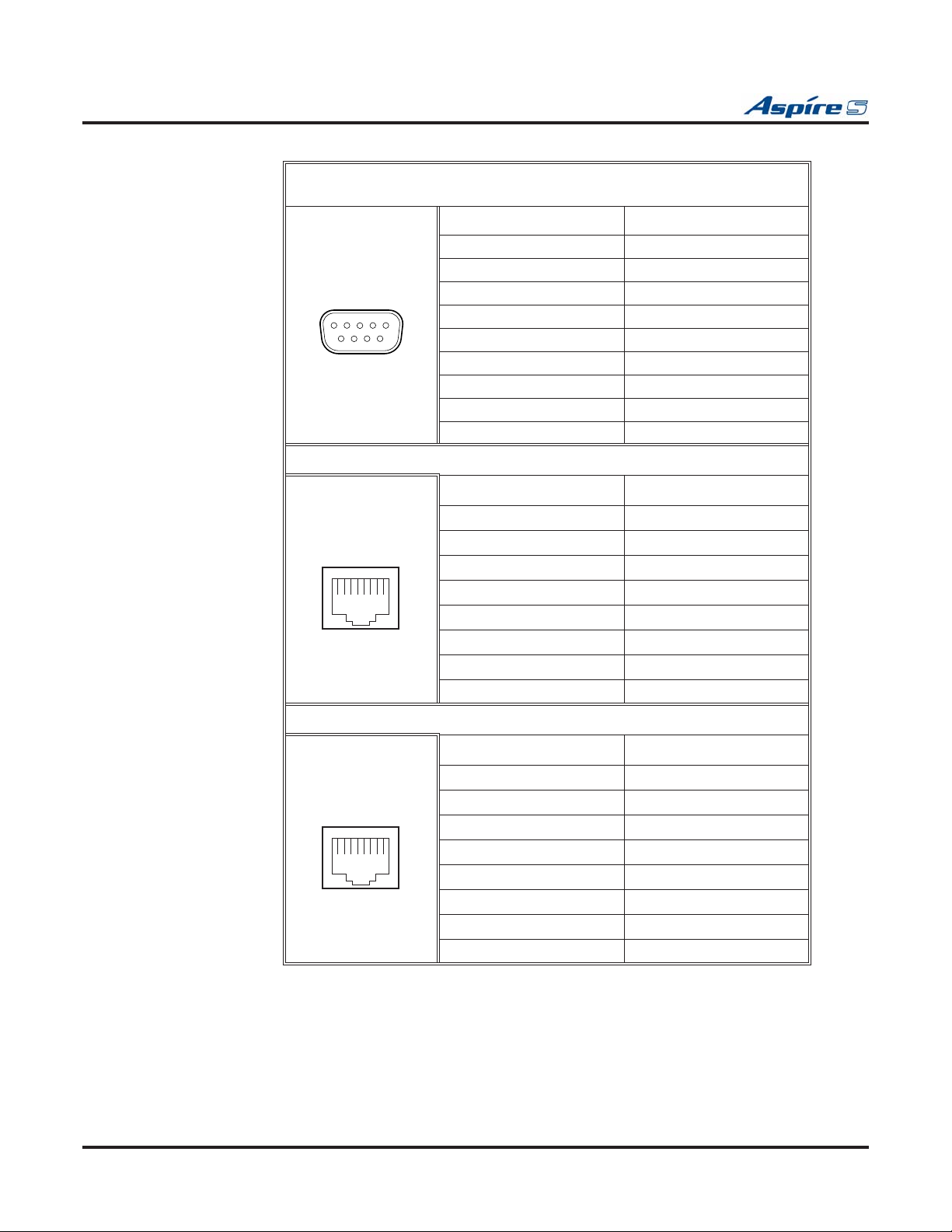
Connector Pin-Outs on CPU
Serial Cable Connector - CN1 (D-Sub 9-Pin Male)
(Null Modem/Cross-Over Cable Used)
Pin No. Signal
1 DCD
2 RxD
12345
6789
Digital Station RJ61 Cable Connector - CN20
12345678
3 TxD
4 DTR
5 GND
6 DSR
7RTS
8 CTS
9-
Pin No. Connection
1 Ring for port 4
2 Ring for port 3
3 Ring for port 2
4 Tip for port 1
5 Ring for port 1
6 Tip for port 2
7 Tip for port 3
8 Tip for port 4
12345678
Digital Station RJ61 Cable Connectors - CN21
Pin No. Connection
1 Ring for port 8
2 Ring for port 7
3 Ring for port 6
4 Tip for port 5
5 Ring for port 5
6 Tip for port 6
7 Tip for port 7
8 Tip for port 8
2-10 ◆ Section 2: PCB Installation and Startup Aspire S Hardware Manual
Page 43
Section 2: PCB Installation and Startup
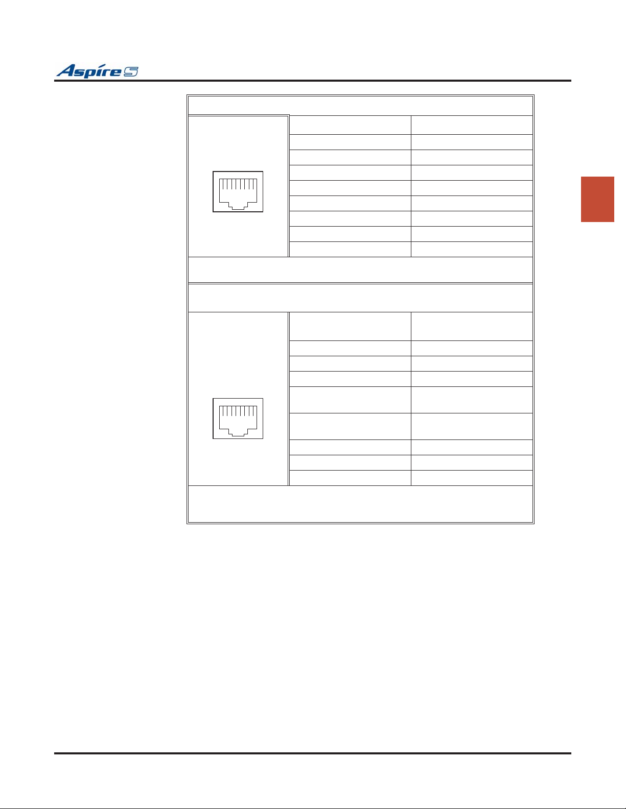
Analog Station RJ61 Cable Connector - CN22
Pin No. Connection
1
2
3 Ring for port 2
12345678
• Polarity reversal feature available
• No Message Wait lamping
External MOH/BGM Source/Relay (External Speaker and Night Mode)
RJ61 Cable Connector - CN23
4 Tip for port 1
5 Ring for port 1
6 Tip for port 2
7
8
2
CPU Connector
12345678
• Pins 4 and 5: External Music on Hold/BGM Input, Input Impedance 600 ohm/
1 kHz
• Pins 3 and 6: Relay = DC Max. 24 VDC, 0.5A - AC Max. 120VAC, 0.25A
Modular Connector
Pin No.
1-
2-
3 EXCNT - Relay
4 EXMOH/BGM Music
5 EXMOH/BGM Music
6 EXCNT - Relay
7-
8-
Signal
Source
Source
CPU Installation
1. Install the battery on the CPU. The polarity “+” symbol must be on top.
2. Install the DSPDBU daughter board if required. Refer to DSPDB Daughter Board (Figure 2-4,
Figure 2-5) (page 2-13).
3. If external BGM or MOH is being installed, plug an RJ61 connector into the CN23 connector on
the CPU. The other end of the cable plugs into the music source.
Refer to the PGDAD Module in the Telephones and Optional Equipment section for details on
connecting to a music source.
Note that Message Waiting lamping is not provided on the two analog ports on the CPU.
4. Assign the purpose of the General Purpose Relay in Program 10-21-01.
Aspire S Hardware Manual Section 2: PCB Installation and Startup ◆ 2-11
Page 44

Section 2: PCB Installation and Startup
● When the system software is upgraded, the flash memory is updated with the new software version. You
can use the Hot or Cold start-up methods or upgrade your system software using the steps which follow.
● Customer information is stored in the RAM memory and, in case of a power failure, will be restored.
The lithium battery in the system saves the RAM memory when power is lost.
Resetting the System:
! IMPORTANT !
While the system is powered up, data may be written to the S-RAM or flash memory at any time.
Before powering down the system, verify that of the 4 LEDs in the lower left corner of the CPU, only
LD2 is flashing (this is the LED located farthest right of the LEDs). It should be flashing 0.5 seconds
on/off (a slow flash). If it’s flashing fast or if any other LEDS are flashing on the CPU, wait until they
stop.
Turning off the power when other LEDs are flashing may corrupt the flash or S-RAM data. If the
flash memory becomes corrupted, the system may not come up. If the S-RAM data is corrupted, the
telephones may have erratic operation.
To Perform a Cold Start:
1. If installed, pull out the compact flash card.
With the compact flash card installed, the system will error and not boot up correctly.
2. Push the power button on the cabinet to power down the system.
When powering the system up or down, wait 10 seconds before pressing the button again. This
allows the system to complete the startup/shutdown process.
3. Once the system has powered down, push in and hold the Load button.
4. Press the power button to power the system back up.
5. Continue holding the Load button for approximately 3 seconds.
6. Release the Load button.
7. When the system has completed reloading the software (approximately 2 minutes), the Status LED
(LD2) will be flashing on the CPU.
To Perform a Hot Start:
System software loaded from flash memory and the customer data is loaded from RAM memory.
1. Push the power button on the cabinet to power down the system. Once it has powered down, wait
10 seconds then press the button again to power the system back up.
When powering the system up or down, wait 10 seconds before pressing the button again. This
allows the system to complete the startup/shutdown process.
2. Wait approximately 2 minutes.
3. When the system has completed reloading the software, the Status LED (LD2) will be flashing on the
CPU.
Performing a Software Upgrade:
Refer to Saving Your Configuration (page 2-44), Backing Up/Restoring a Database (page 2-44), Using
Flash Cards for System Software (page 2-45), and Upgrading Software (page 2-46) for complete details
on how to work with the system software with the CPU.
2-12 ◆ Section 2: PCB Installation and Startup Aspire S Hardware Manual
Page 45
Section 2: PCB Installation and Startup
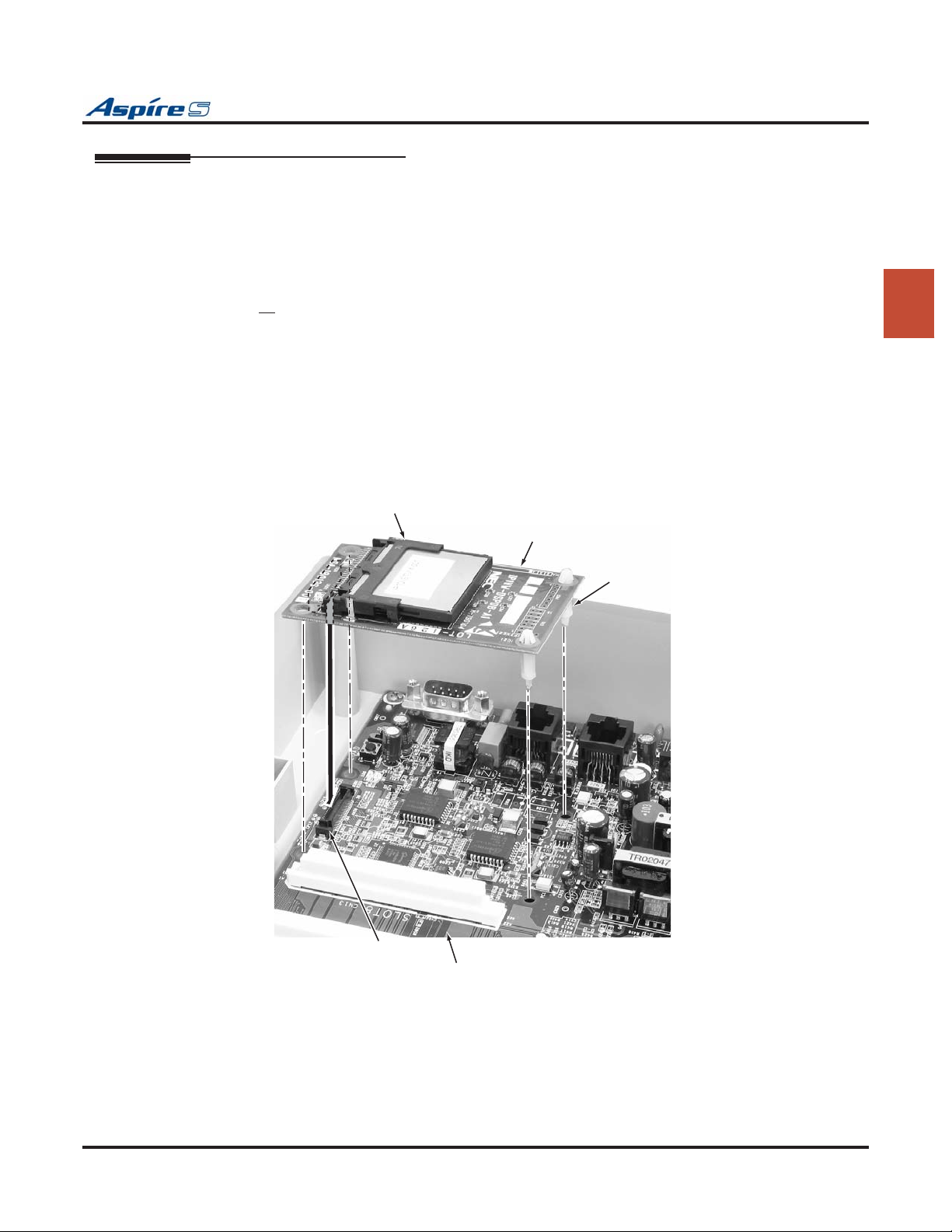
DSPDB Daughter Board (Figure 2-4, Figure 2-5)
The DSPDB provides the option for the VRS (Voice Response System) feature. This daughter board is
mounted on the CPU and provides:
● 8 VRS Circuits with a VRS Flash Card Installed (replays up to 8 circuits simultaneously; records up to 8 cir-
cuits simultaneously)
● Compact Flash Slot for VRS or IntraMail Feature
There are no DTMF receivers provided when this daughter board is installed on the CPU.
To install a DSPDB Daughter Board:
1. Included with the DSPDB are four spacers. Install one spacer in each corner of the daughter board.
Make sure to attach the spacers from the back of the daughter board so when installed, the compact
flash slot is facing up.
2. Position the daughter board over the CN4 connector on the CPU. Push the board into the connector
on the CPU. Gently push the corners of the daughter board down so the spacers lock into the CPU.
To remove the daughter board, use pliers to squeeze the top of the spacers together, then gently
pull the daughter board off.
CN1
DSPDB
Spacers
0893130-25
2
CN4
CPU
Figure 2-4: DSPDB DAUGHTER BOARD INSTALLATION
Aspire S Hardware Manual Section 2: PCB Installation and Startup ◆ 2-13
Page 46
Section 2: PCB Installation and Startup
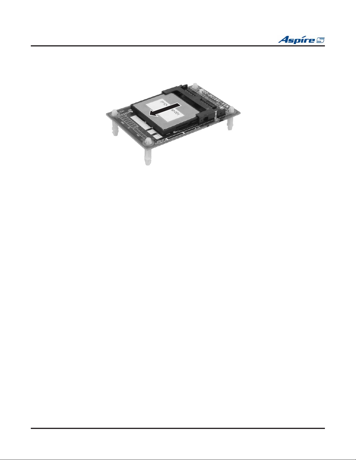
To Upgrade the DSPDB Compact Flash Card:
1. With the system power off, remove the compact flash card from the DSPDB daughter board.
2. Insert the new compact flash card.
Figure 2-5: REMOVING THE COMPACT FLASH CARD
0893100 - 90
2-14 ◆ Section 2: PCB Installation and Startup Aspire S Hardware Manual
Page 47
Section 2: PCB Installation and Startup
LAN Connection (ENTU) PCB (Figure 2-6)
An ENTU PCB is required when a VoIP PCB is installed. If the ENTU is not installed, the system
will not start up. In addition, an ENTU would be required for a WebPro/PCPro LAN connection.
The ENTU PCB provides a LAN connector which is compatible with 100Base-TX and 10Base-T. This PCB
is compatible in LAN applications using 10Mbps and 100Mbps. All ports will automatically identify and
switch 100Base-TX, 10Base-T and Full/Half Duplex.
The VoIP PCB, which is required in order for IP telephones to communicate with non-VoIP Aspire phones,
as well as to place or receive outside calls, must be connected to an external switching hub.
The PCB plugs into the CN6 and CN7 connectors on the CPU, with a maximum of 1 per system. Each PCB
provides an RJ61 port connector. This is used to connect to a LAN terminal or external switching hub.
Depending on the type of LAN terminal, the PCB may not be able to detect the difference between straight
cable and cross-cable automatically. If auto-crossover is not functioning, use straight cable for that terminal
connection.
If PoE (power over ethernet) is to be used to eliminate the separate power adapters, a separate power source
is required. It is recommended that you use a power switch and/or power hub which is IEEE 802.3AF compliant. For example, the PowerDsine 6xxx series of products is unique in the fact that in addition to offering
IEEE 802.3AF support, it also provides for the NEC proprietary detection and, therefore, the ILPA (In Line
Power Adapter) is not required. For systems which require layer 2 switching capability and PoE, the NEC
BlueFire 200/24 switch is recommended. This unit provides layer 2 switch capability in addition to being
able to supply ethernet power to 24 NEC IP terminals. For this unit, power feeding is through the signal pair
(1/2, 3/6) or spare pair (4/5, 7/8).
2
Refer to Section 6: LAN Connection (page 6-1) for additional information on using PoE on the Aspire.
Specifications
● LAN Family Standard: Complies with 10Base-T and 100Base-TX (IEEE802.3)
● Access Method: CSMA/CD
● Transmission Line/Channel Interface: 10Base-T/100Base-TX = 1 port
● LAN Family Interface (Layer 1):
Transmission Speed: 10Mbps/100Mbps Auto Negotiation
Cable: LAN Category 5 or higher - Straight/Cross cable auto negotiation (auto crossover)
LED Indications
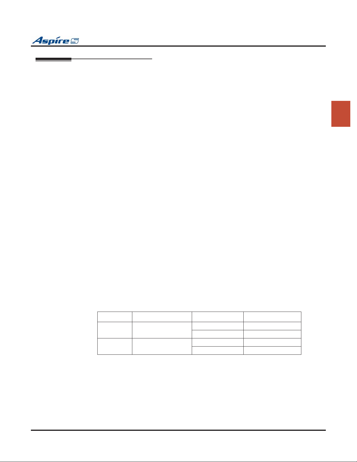
LED Function LED Status Operation Status
LD1
ACT
LD2
LINK
LAN Operation Status Green Flashing Communicating Data
Green Off Not Activated
LAN Operation Status Red On Link Established
Red Off No Link
Aspire S Hardware Manual Section 2: PCB Installation and Startup ◆ 2-15
Page 48
Section 2: PCB Installation and Startup
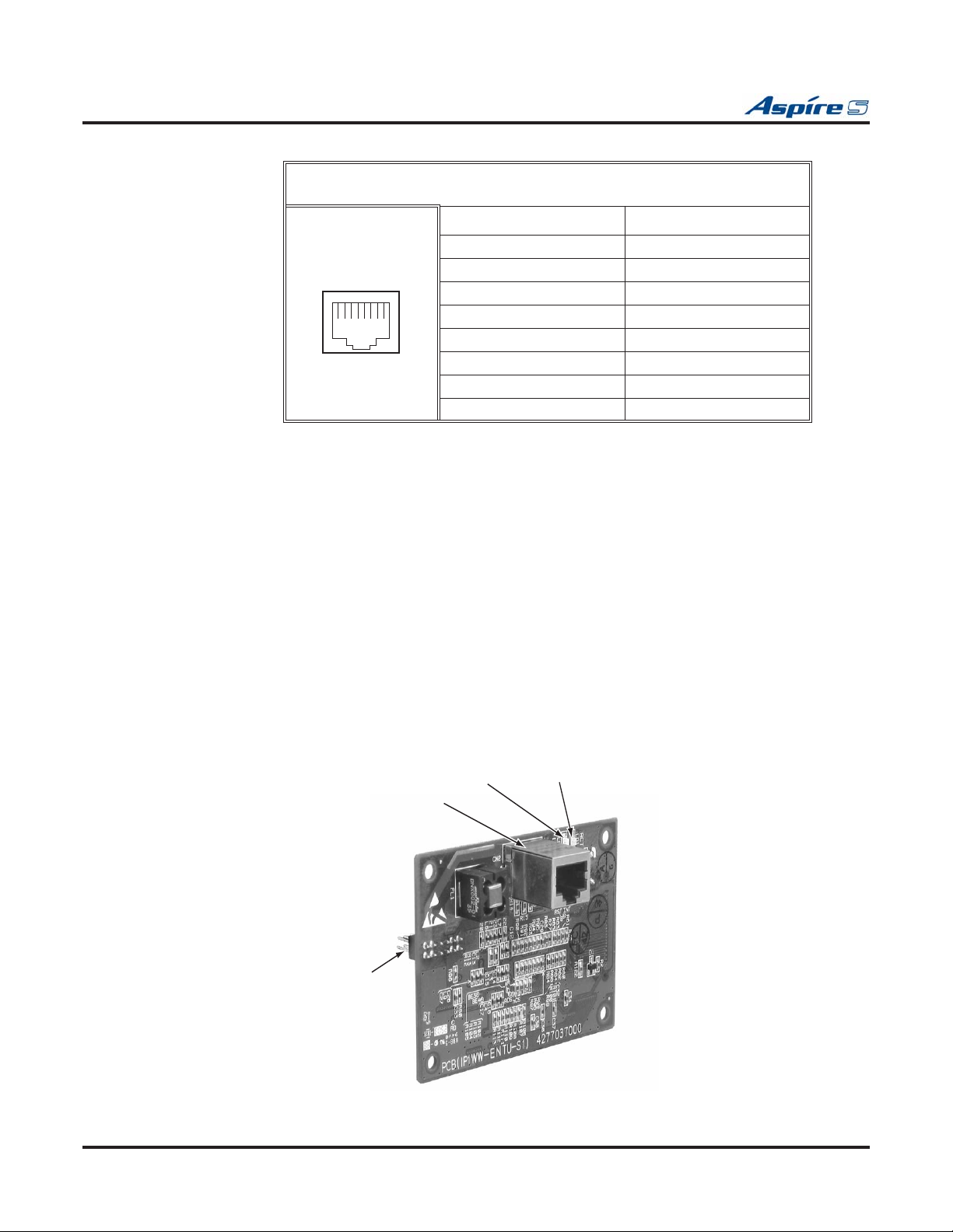
Connector Pin-Outs on ENTU
Ethernet Cable Connector - CN2 (RJ45)
(10Base-T/100Base-TX Port)
Pin No. Signal
1 Tx+
2 Tx-
3 Rx+
12345678
Installing the ENTU:
1. Included with the ENTU is one plastic spacer. Install the spacer in the corner of the daughter board
which will not have a support provided by the CPU. Make sure to attach the spacer from the back of
the daughter board so when installed, the connectors are facing up.
2. Position the ENTU PCB over the CN6 connector on the CPU. Push the board into the connector on
the CPU. Gently push the corner of the daughter board down so the spacer locks into the CPU.
To remove the daughter board, use pliers to squeeze the top of the spacer together, then gently
pull the daughter board off.
3. Using the three screws provided with the ENTU PCB, secure the remaining three corners of the
PCB to the CPU.
Once the system has been powered up, with normal operation, the status LED will flash fast. If
trouble was found during the self diagnostics routine, the status LED will flash slowly.
4. Using the ferrite core provided with the ENTU PCB, wrap the end of the ethernet cable which is
closest to the ENTU’s CN2 connector once around the ferrite core.
5. Plug the ethernet cable into the CN2 connector.
6. Refer to the Aspire Software Manual (P/N 0893200) or the VoIP Feature Supplement (P/N
0893204) for required VoIP programming.
4-
5-
6 Rx-
7-
8-
LD2 Link/Act LED
CN2 - RJ 45 Ethernet
Connector
CN3
CPU Connection
(For earth ground)
LD1 10/100 Port Status LED
0-32
089313
Figure 2-6: ENTU INSTALLATION
2-16 ◆ Section 2: PCB Installation and Startup Aspire S Hardware Manual
Page 49
Section 2: PCB Installation and Startup
Digital Station (8ESIU-S) PCB (Figure 2-7)
The 8ESIU-S PCB provides:
● 8 digital extension circuits (used for digital telephones, DSS consoles, 1SLTAD adapters, 2PGDAD
adapters)
The 8ESIU-S is not rated for OPX use. It is recommended that a 2DIOPU-S PCB be used instead (it
supports analog DID and single line telephone interface functions, such as Off-Premise Extensions).
● 1 extension status LED (indicates status for 4 extensions)
● 1 PCB status LED
The CN3 and CN4 connectors each provide connection to 4 digital station ports. The ESIU-S requires one
universal slot, with a maximum of 2 PCB’s per system. Note that this PCB can not be installed in slot 7 or 8.
The 8ESIU-S consumes 8 ports ranging between ports 01-26. There must be enough available ports in order
for the Aspire system to recognize an 8ESIU-S PCB.
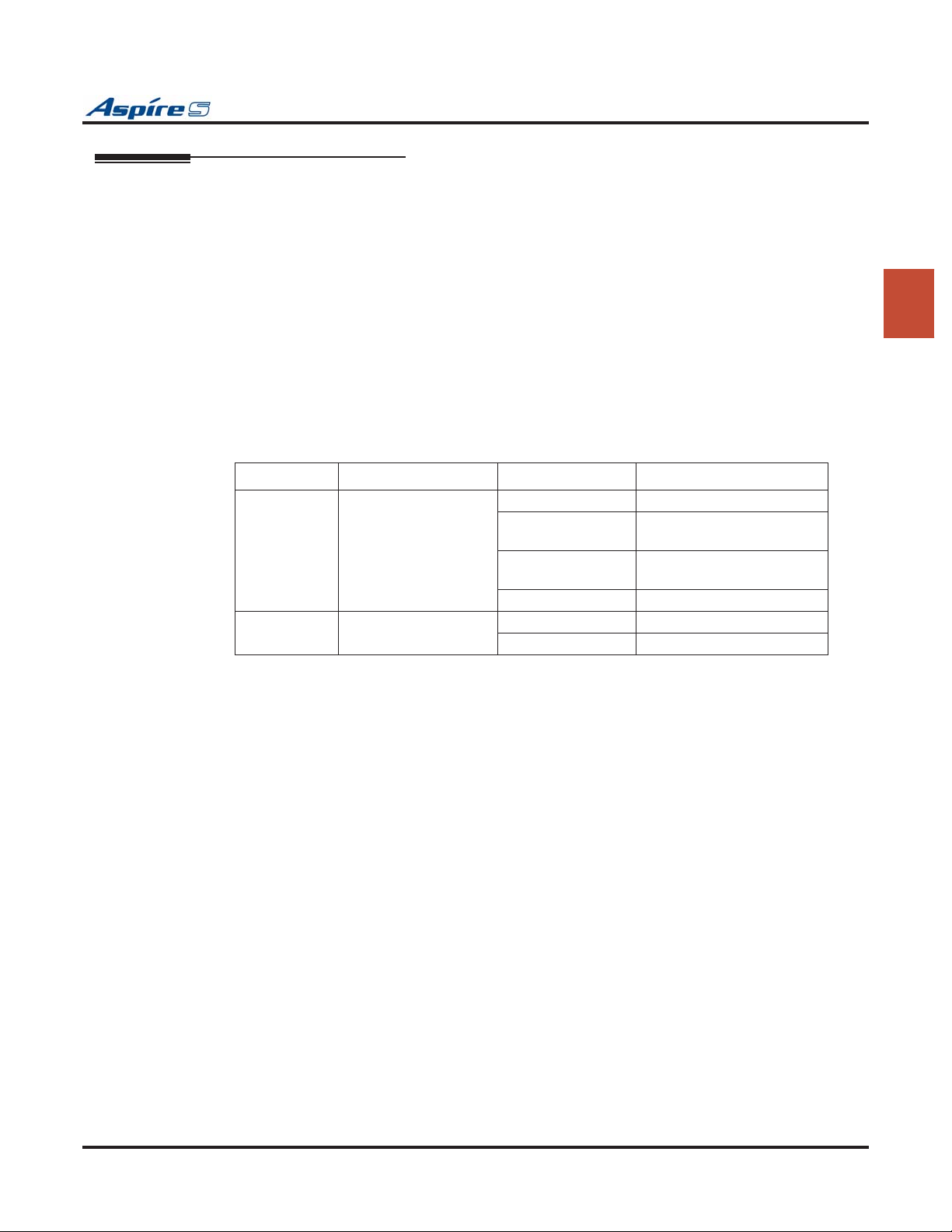
LED Indications
LED Function LED Status Operation Status
LD2
(PCB Status)
LD1 Indicates the status of
Indicates the status of
the PCB.
terminals 1-8.
Green On Initializing
Green Flashing
(slow flash)
Green Flashing
(100ms On/Off)
Green Off Downloading
Red On Terminal in use
Red Off Terminal idle
Initialization problem
occurred during self-check.
Operating normally
2
Aspire S Hardware Manual Section 2: PCB Installation and Startup ◆ 2-17
Page 50
Section 2: PCB Installation and Startup
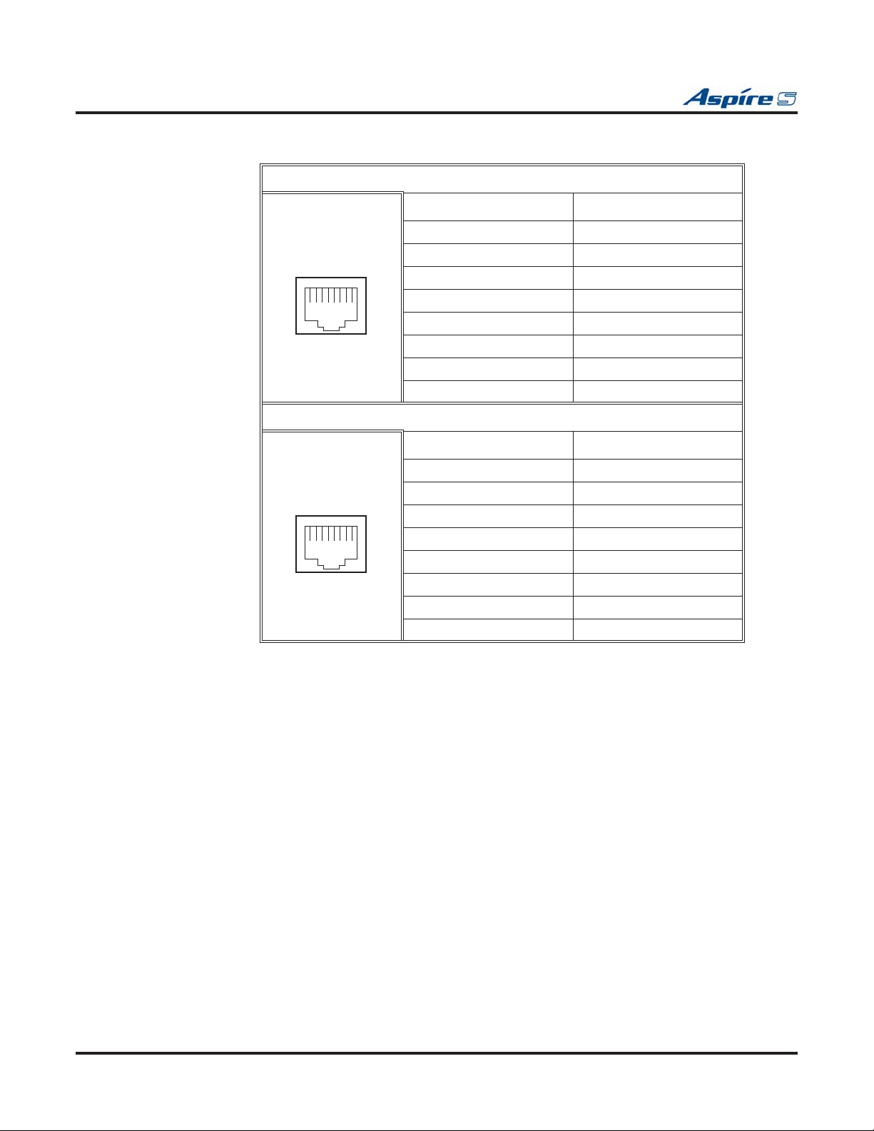
Connector Pin-Outs on ESIU
RJ61 Cable Connector - CN4
Pin No. Connection
1 Ring for port 4
2 Ring for port 3
3 Ring for port 2
12345678
RJ61 Cable Connector - CN3
12345678
4 Tip for port 1
5 Ring for port 1
6 Tip for port 2
7 Tip for port 3
8 Tip for port 4
Pin No. Connection
1 Ring for port 8
2 Ring for port 7
3 Ring for port 6
4 Tip for port 5
5 Ring for port 5
6 Tip for port 6
7 Tip for port 7
8 Tip for port 8
2-18 ◆ Section 2: PCB Installation and Startup Aspire S Hardware Manual
Page 51
Section 2: PCB Installation and Startup
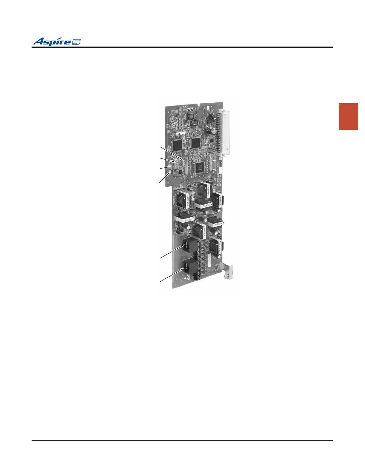
To install the ESIU PCB:
1. Install the ESIU into a slot.
Note that this PCB can not be installed in slot 7 or 8.
2. Tighten the screw on the PCB to secure the card to the cabinet.
CN7
CN6
2
PCB Status LED
Live Status LED
LD2
LD1
CN3
CN4
Figure 2-7: ESIU INSTALLATION
0893130-29
Aspire S Hardware Manual Section 2: PCB Installation and Startup ◆ 2-19
Page 52
Section 2: PCB Installation and Startup
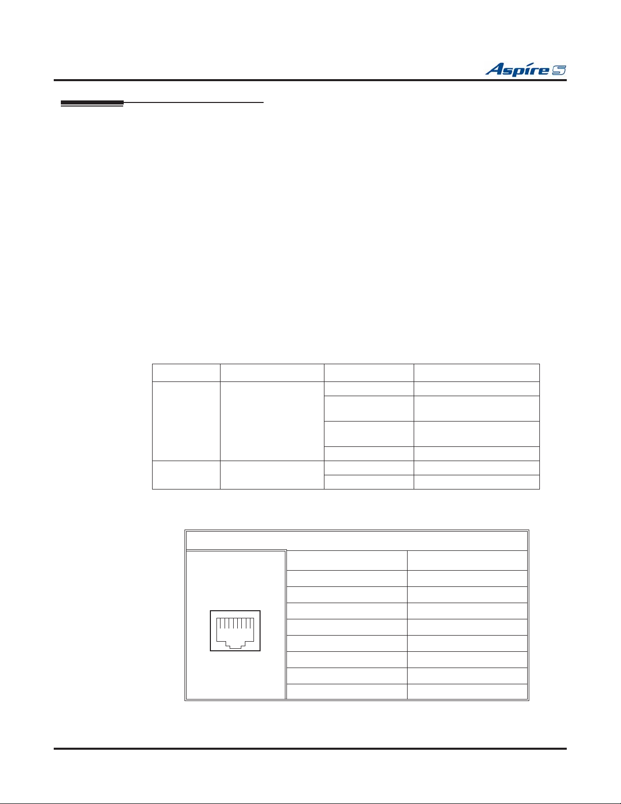
Analog Station (4SLIU-S) PCB (Figure 2-8)
The 4SLIU-S PCB provides:
● 4 analog extension ports (used for on-premise analog telephones, fax machines, and analog modems)
The 4SLIU-S is not rated for OPX use. It is recommended that a 2DIOPU-S PCB be used instead (it
supports analog DID and single line telephone interface functions, such as Off-Premise Extensions).
● 4 extension status LEDs
● 1 PCB status LED
● Connector for 4SLIDB-S Daughter Board
● Ring Generator
● Message Wait Lamping Ability
Note: When connecting a fax machine or analog modem, make sure to set Program 15-03-03 to
‘1’ (special terminal) to avoid communication problems.
The CN3 connector provides connection to 4 analog station ports and are not polarity sensitive. The
4SLIU-S is installed in a universal slot with a maximum number of 4 PCBs per system. This number of
PCBs installed will reduce the number of 4SLIDB-S PCBs which can be installed. If 3 4SLIU-S PCBs are
installed, only 1 4SLIDB-S can be installed. If 4SLIU-S PCBs are installed, the 4SLIDB-S can not be used.
There must be enough available ports in order for the Aspire system to recognize an 4SLIU-S PCB.
LED Indications
LED Function LED Status Operation Status
LD1
(PCB Status)
LD2 - LD5 Indicates the status of
Indicates the status of
the PCB.
terminals 1-4.
Green On Initializing
Green Flashing
(slow flash)
Green Flashing
(100ms On/Off)
Green Off Downloading
Red On Terminal in use
Red Off Terminal idle
Initialization problem
occurred during self-check.
Operating normally
Connector Pin-Outs on 4SLIU-S
RJ61 Cable Connector - CN3
Pin No. Connection
1 CH4 L1 (tip for port 4)
2 CH3 L1 (tip for port 3)
3 CH2 L1 (tip for port 2)
12345678
4 CH1 L2 (ring for port 1)
5 CH1 L1 (tip for port 1)
6 CH2 L2 (ring for port 2)
7 CH3 L2 (ring for port 3)
8 CH4 L2 (ring for port 4)
2-20 ◆ Section 2: PCB Installation and Startup Aspire S Hardware Manual
Page 53
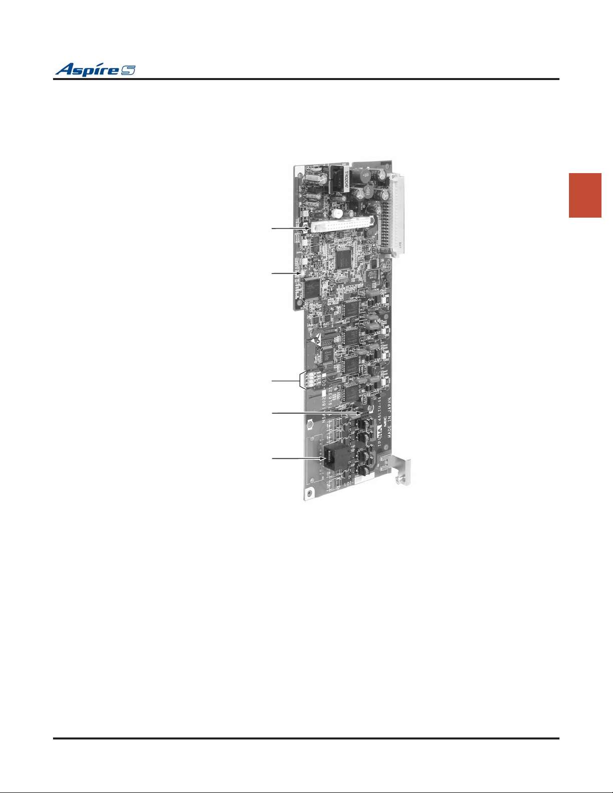
Section 2: PCB Installation and Startup
Installing an 4SLIU-S PCB:
1. If the 4SLIDB-S is to be used, install this prior to inserting the 4SLIU-S PCB into the cabinet.
2. Install the 4SLIU-S into the slot.
3. Tighten the screw on the PCB to secure the card to the cabinet.
CN5 4SLIDB Connector
LD1 PCB Status LED
2
LD2 - LD5
Line Status LEDs
CN4
Earth Ground Connection
SLIDB PCB
CN3
Figure 2-8: 4SLIU-S INSTALLATION
0893130-30
Aspire S Hardware Manual Section 2: PCB Installation and Startup ◆ 2-21
Page 54
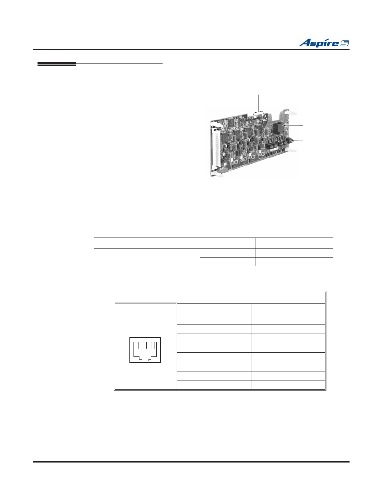
Section 2: PCB Installation and Startup
Analog Station (4SLIDB-S) Daughter Board (Figure 2-9 - Figure 2-10)
The 4SLIDB-S daughter board provides:
● 4 analog extension ports (used for on-
premise analog telephones, fax machines,
and analog modems)
● Connector for 4SLIU-S PCB
● Ring Generator
● Message Wait Lamping Ability
Note: When connecting a fax
machine or analog modem, make sure
to set Program 15-03-03 to ‘1’ (special
terminal) to avoid communication
problems.
Live Status LEDs (on back of PCB)
LD1 - LD4
0893130-31
CN3
Analog Ports 1-4
CN4
SLIU PCB Earth Ground
Connector
The CN3 connector provides connection to 4
Figure 2-9: 4SLIDB-S PCB
analog station ports and are not polarity sensitive. The 4SLIDB-S is installed on the 4SLIU-S
PCB. Up to 2 PCBs can be installed in the system maximum, but this number may be reduced depending on
how many 4SLIU-S PCBs are installed. If 3 4SLIU-S PCBs are installed, only 1 4SLIDB-S can be installed.
If 4SLIU-S PCBs are installed, the 4SLIDB-S can not be used.
LED Indications
LED Function LED Status Operation Status
LD1 - LD4 Indicates the status of
terminals 5-8.
Red On Terminal in use
Red Off Terminal idle
Connector Pin-Outs on 4SLIDB-S
RJ61 Cable Connector - CN3
Pin No. Connection
1 CH4 L1 (tip for port 4)
2 CH3 L1 (tip for port 3)
3 CH2 L1 (tip for port 2)
12345678
4 CH1 L2 (ring for port 1)
5 CH1 L1 (tip for port 1)
6 CH2 L2 (ring for port 2)
7 CH3 L2 (ring for port 3)
8 CH4 L2 (ring for port 4)
2-22 ◆ Section 2: PCB Installation and Startup Aspire S Hardware Manual
Page 55
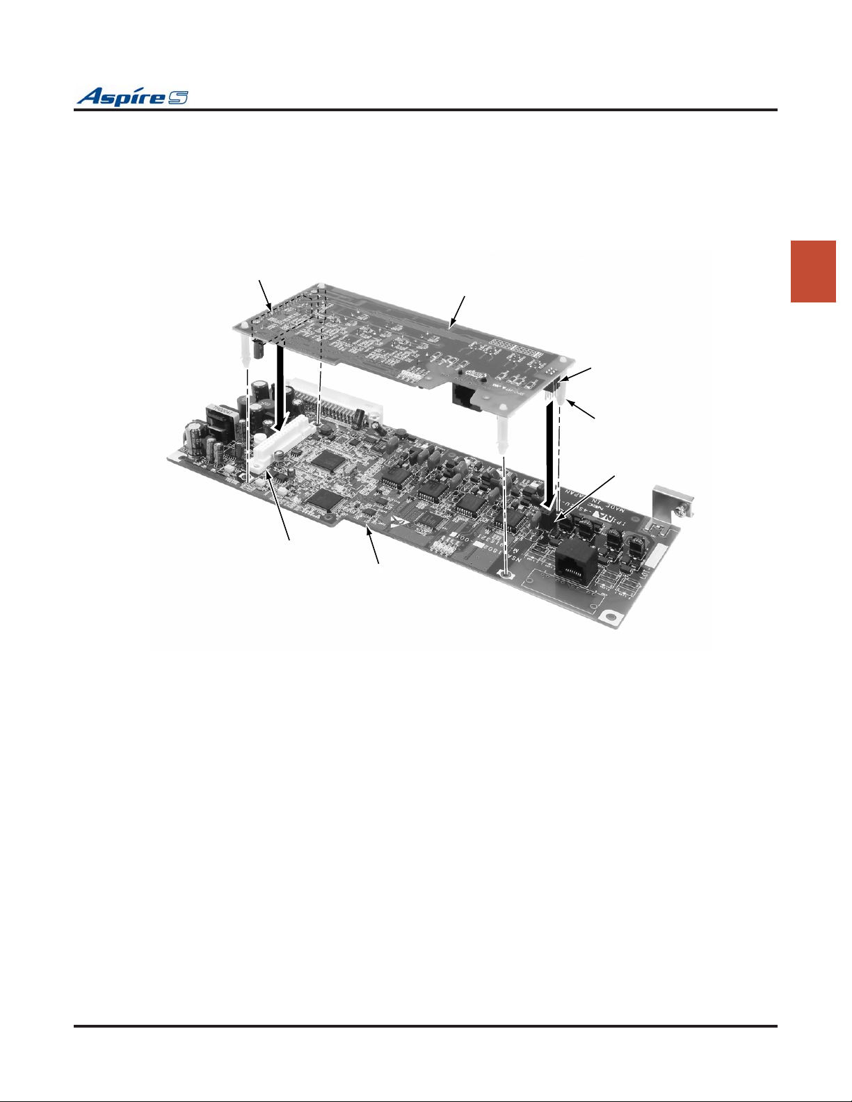
Section 2: PCB Installation and Startup
Installing an 4SLIDB-S Daughter Board:
1. Included with the 4SLIDB-S are four plastic spacers. Place a plastic spacer in each corner of the
PCB. Make sure to attach the spacers on the front of the daughter board so when installed, the components are facing the 4SLIU-S PCB.
2. Position the 4SLIDB-S’s CN1 connector over the CN5 connector on the 4SLIU-S PCB. Press the
boards together, ensuring the plastic spacers lock in place.
3. Install the 4SLIU-S PCB into the slot.
CN1
4SLIDB
CN5
4SLIU
Figure 2-10: 8SLIDB-S INSTALLATION
CN4
Spacers
CN4
0893130
2
24
-
Aspire S Hardware Manual Section 2: PCB Installation and Startup ◆ 2-23
Page 56
Section 2: PCB Installation and Startup
Analog Trunk (4COIU-S) PCB (Figure 2-11)
The Analog Trunk (COIU-S) PCB provides:
● 4 analog loop start line/trunk circuits - no ground start is provided
● 4 trunk status LEDs
● 4 Caller ID Circuits
● 1 Power Failure Transfer Circuit
● 1 PCB status LED
The CN5 and CN7 connectors each provide connection to 2 analog trunk ports, which are polarity sensitive
(tip to tip, ring to ring). The power failure circuit, however, is not polarity sensitive. A maximum of 2
4COIUs per system is allowed.
LED Indications
LED Function LED Status Operation Status
LD5
(PCB Status)
LD1 - LD4 Indicates the status of
Indicates the status of
the PCB.
the lines.
Green On Initializing
Green Flashing
(slow flash)
Green Flashing
(100ms On/Off)
Green Off Downloading
Red On Line in use
Red Off Line idle
Initialization problem
occurred during self-check.
Operating normally
2-24 ◆ Section 2: PCB Installation and Startup Aspire S Hardware Manual
Page 57
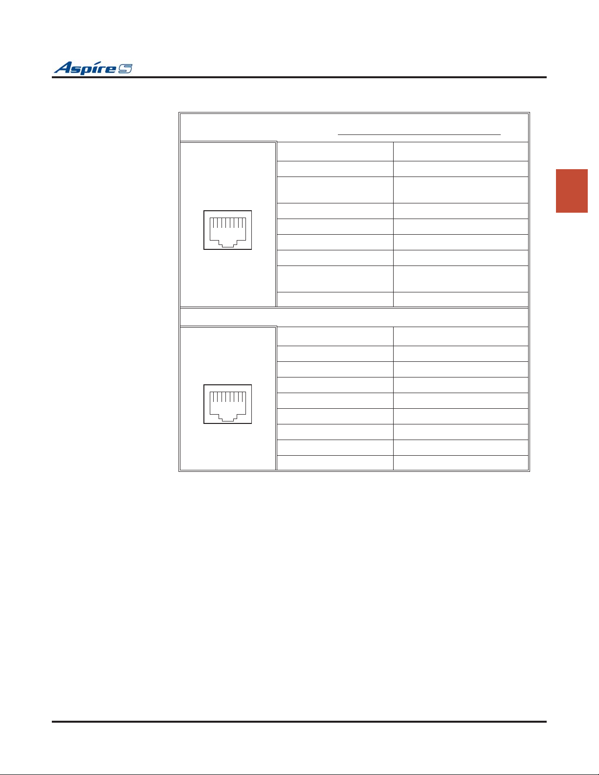
Section 2: PCB Installation and Startup
Connector Pin-Outs on COIU-S PCB
The CN5 and CN7 connectors are polarity sensitive (tip to tip, ring to ring).
12345678
12345678
RJ61 Cable Connector - CN5
Pin No. Connection
1-
2 SLT Interface
Power Failure Circuit - Tip
3 Circuit 2 - Tip
4 Circuit 1 - Ring
5 Circuit 1 - Tip
6 Circuit 2 - Ring
7 SLT Interface
Power Failure Circuit - Ring
8-
RJ61 Cable Connector - CN7
Pin No. Connection
1-
2-
3 Circuit 4 - Tip
4 Circuit 3 - Ring
5 Circuit 3 - Tip
6 Circuit 4 - Ring
7-
8-
2
Aspire S Hardware Manual Section 2: PCB Installation and Startup ◆ 2-25
Page 58

Section 2: PCB Installation and Startup
Installing the Analog Trunk PCB:
1. Install the COIU-S into a slot.
The trunk ports are polarity sensitive (tip to tip, ring to ring). Be sure the wiring is correct.
Once the system is powered up, with normal operation, the status LED will flash fast. If trouble
was found during the self diagnostics routine, the status LED will flash slowly.
2. Tighten the screw on the PCB to secure the card to the cabinet.
.
Figure 2-11: 4COIU-S INSTALLATION
2-26 ◆ Section 2: PCB Installation and Startup Aspire S Hardware Manual
Page 59
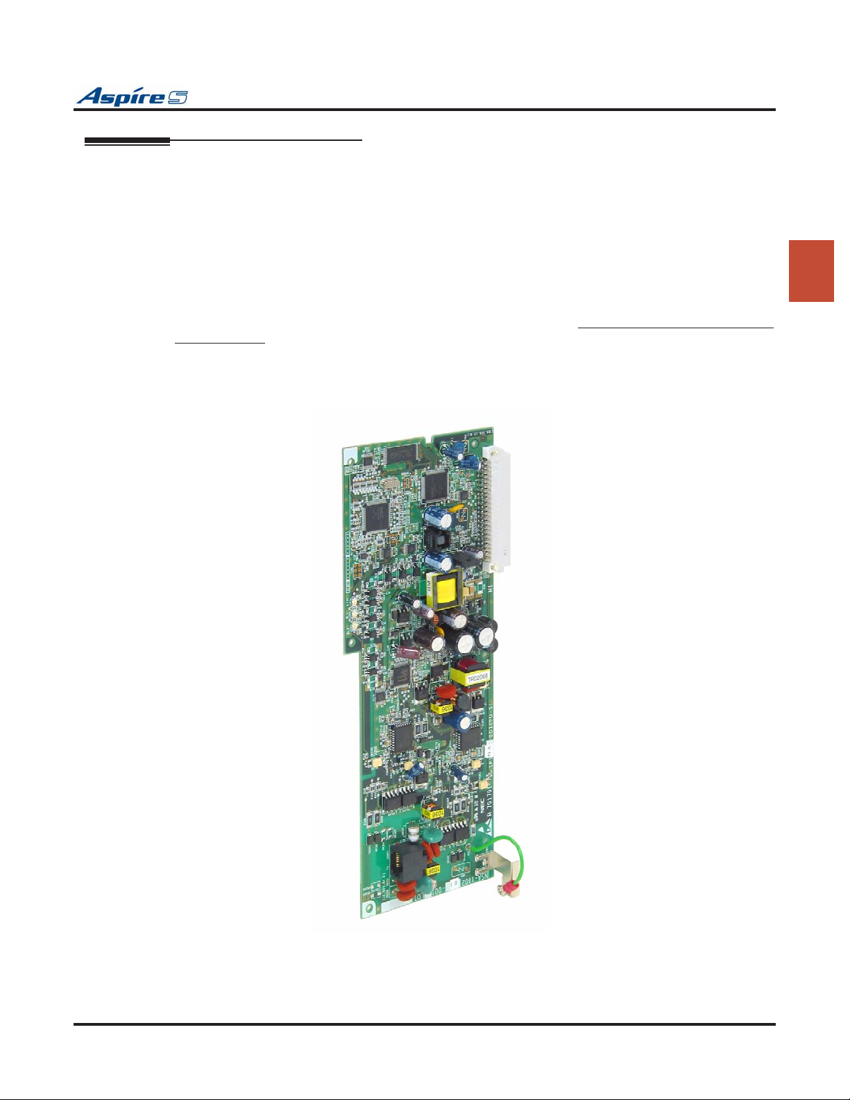
Section 2: PCB Installation and Startup
Direct Inward Dial (DID) (2DIOPU-S) PCB (Figure 2-12)
The 2DIOPU-S PCB, with software 2.21 or higher, supports the analog DID and single line telephone interface functions (such as Off-Premise Extension). The function type is assigned in programming for each port.
The DIOPU-S PCB provides:
● 2 DID/OPX trunk circuits
● 2 DID/OPX trunk status LEDs
● 1 PCB status LED
● 1 PBXG Grounding Wire
The CN201 connector provides connection to 2 analog DID trunk ports, which are polarity sensitive (tip to
tip, ring to ring). The OPX circuits, however, are not polarity sensitive. The DIOPU-S requires one universal
slot, with 4 maximum PCBs per system. The system will assign either trunk or extension ports to the PCB
based on the system programming (10-03-01). The PCB provides track resistance of 1500 ohms (PB loop)
and 3000 ohms (DP loop) which includes the DC resistance of the terminal.
.
2
Figure 2-12: 2DIOPU-S INSTALLATION
Aspire S Hardware Manual Section 2: PCB Installation and Startup ◆ 2-27
Page 60
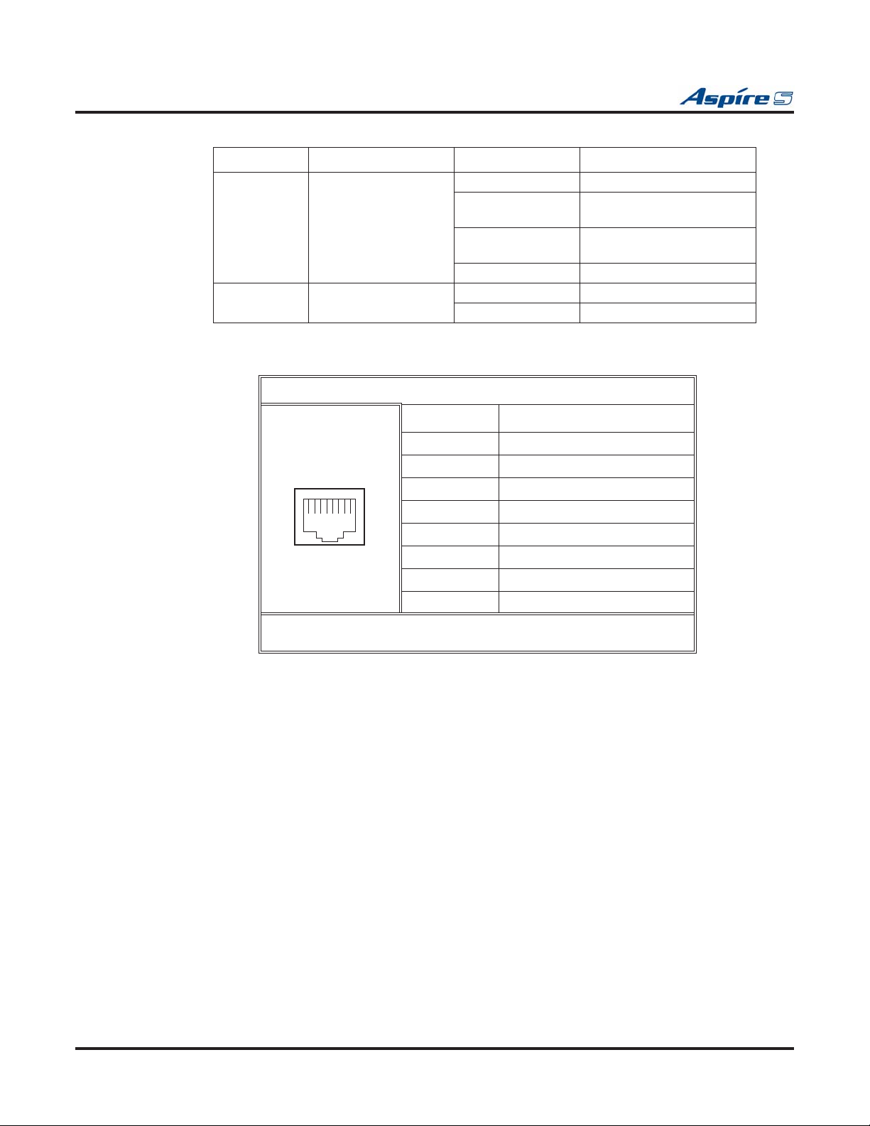
Section 2: PCB Installation and Startup
LED Indications
LED Function LED Status Operation Status
LD1
(PCB Status)
LD2 - LD3 Indicates the status of
Connector Pin-Outs on DIOPU-S PCB
• Connect the tip to the ground side and the ring to the -48V side when
Indicates the status of
the PCB.
the lines.
RJ61 Cable Connector - CN201
12345678
wiring for analog DID trunk ports.
Green On Initializing
Green Flashing
(slow flash)
Green Flashing
(100ms On/Off)
Green Off Downloading
Red On Line in use
Red Off Line idle
Pin No. Connection
1 N/A
2 N/A
3 Tip for port 2
4 Ring for port 1
5 Tip for port 1
6 Ring for port 2
7 N/A
8 N/A
Initialization problem
occurred during self-check.
Operating normally
Installing the Direct Inward Dial PCB:
1. Install the DIOPU-S PCB into a slot.
2. Connect the PBXG grounding wire to the PBXG grounding terminal in the cabinet.
The analog DID trunk ports are polarity sensitive (tip to tip, ring to ring). The OPX circuits,
however, are not polarity sensitive. Be sure the wiring is correct for the application.
Once the system is powered up, with normal operation, the status LED will flash fast. If trouble
was found during the self diagnostics routine, the status LED will flash slowly.
3. Tighten the screw on the PCB to secure the card to the cabinet.
2-28 ◆ Section 2: PCB Installation and Startup Aspire S Hardware Manual
Page 61
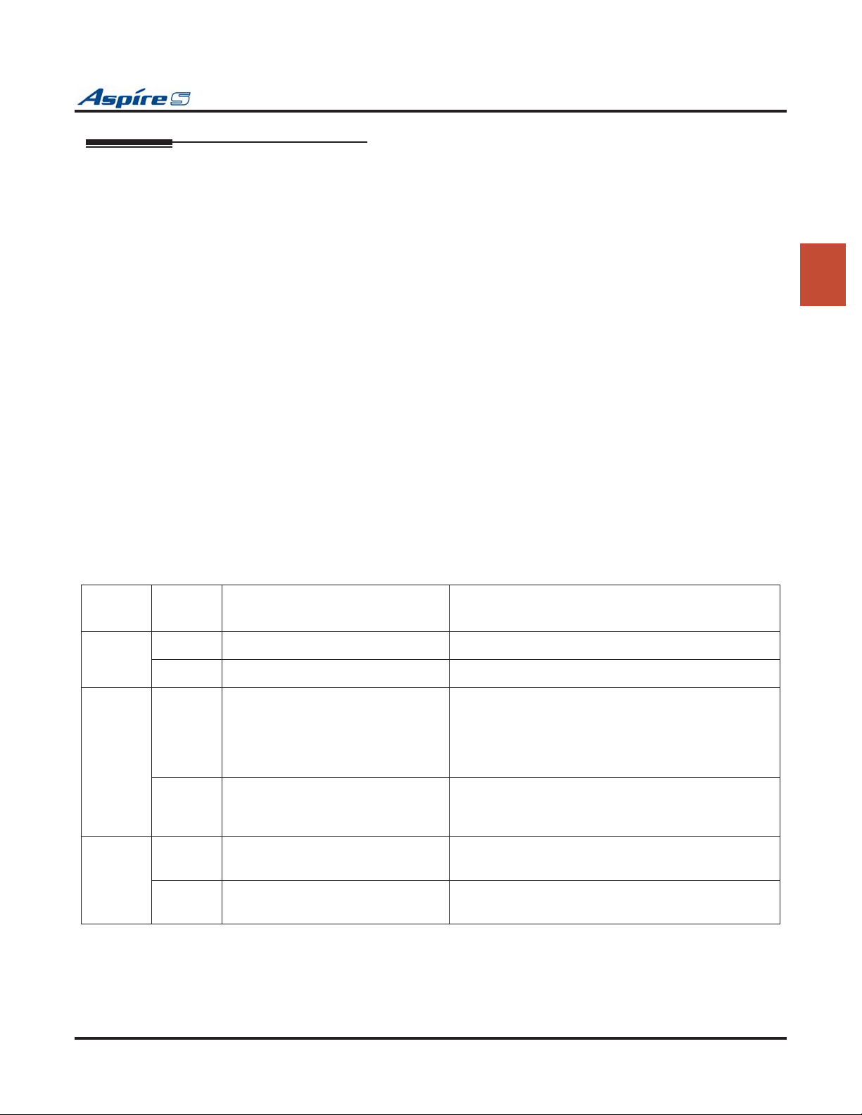
Section 2: PCB Installation and Startup
BRI (2BRIU-S) Interface PCB (Figure 2-13)
Check with your NEC Sales Representative for availability of this PCB.
The BRI PCB provides:
● 2 2-Channel Circuits (2B + D) configured as T-Bus
● 64 Kb/s Clear B-Channel and 16 Kb/s D-Channel
● 4 trunk/extension status LEDs
● 1 PCB status LED
● 1 run/block switch
The BRI Interface PCB uses a single universal slot. A maximum of 2 BRIU-S PCBs can be installed when
used as T-Bus. Each PCB connects to the network via an NTI Network Termination. With the maximum
number of PCBs installed, the following can be provided:
● The 2BRIU-S, when used as T-Bus, provides 2 BRI circuits and 4 BRI channels. A maximum of 7
ISDN terminals can be connected between an external DSU and the 2BRIU-S PCB.
The trunk circuit can be connected to either an ISDN trunk or ISDN telephone set, depending on the SW102
and SW202 switch settings.
Setting the SW100-SW200 Switches
In the following cases, the SW100-SW200 switches should be set to the ON position:
● When the channel is assigned as a T-Bus Point-to-Point.
● With T-Bus Point-to-Multipoint and if the system is connected at the end of the multipoint.
2
Switch
Name
SW102
SW202
SW100
SW200
CN102
CN202
Otherwise, the SW100-SW200 switches should be set to the OFF position.
Switch
Position
T T-Bus Connection
S S-Bus Connection Not currently used.
ON Termination resistor is ON This switch should be set to ON:
OFF Termination resistor is OFF When T-Bus with Point-to-Multipoint is selected and if
ON With S-Bus selected, the Feeding
Power is supplied to the terminal.
OFF With S-Bus selected, the Feeding
Power is not supplied to the terminal.
Result Comments
1. When T-Bus with Point-to-Point is selected.
2. When T-Bus with Point-to-Multipoint is selected
and if the connection to the Aspire system at the last
port of the Bus connection.
the Aspire system is not connected to the last port of the
Bus connection, this switch should be OFF.
- Not currently used. If S-Bus is selected, this switch should be ON.
- Not currently used. If T-Bus is selected, this switch should be OFF.
Aspire S Hardware Manual Section 2: PCB Installation and Startup ◆ 2-29
Page 62
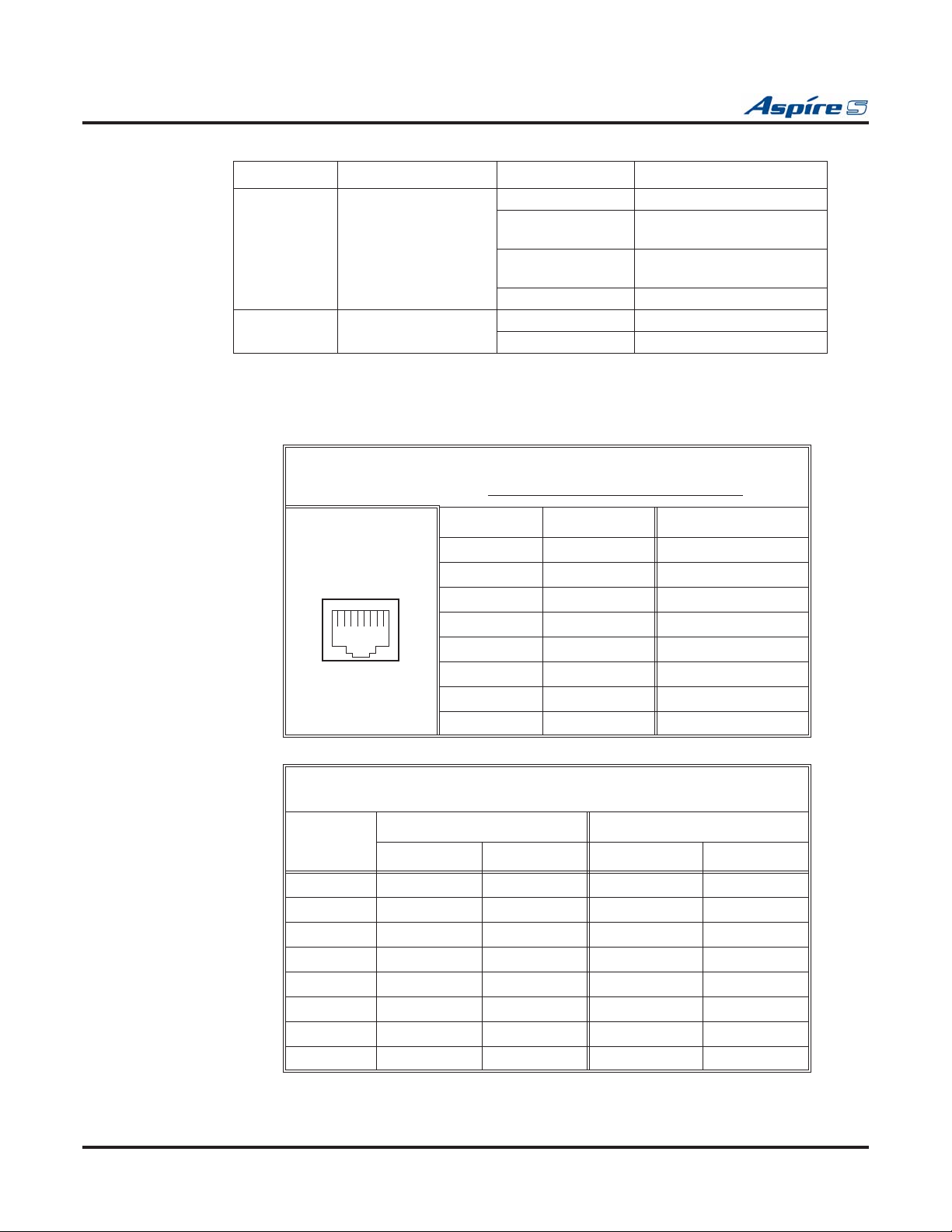
Section 2: PCB Installation and Startup
LED Indications
LED Function LED Status Operation Status
LD5
(PCB Status)
LD1 - LD2 Indicates the Layer 1
Connector Pin-Outs on BRIU-S PCB
Indicates the status of
the PCB.
link status of the lines.
RJ61 Cable Connector - CN2
The CN2 connector is polarity sensitive (tip to tip, ring to ring).
12345678
Green On Initializing
Green Flashing
(slow flash)
Green Flashing
(100ms On/Off)
Green Off Downloading
Red On Layer 1 link established
Red Off No link
T-Bus Connection
Pin No. Connection
1-
2-
3 TA +
4 RA +
5 RB -
6 TB -
7-
8-
Initialization problem
occurred during self-check.
Operating normally
Pin-Out for ISDN Cable at External DSU and Mod Jack
Connection on DSU Side Connection on Mod Jack
Pin No.
Terminal DSU Terminal DSU
1- - - -
2- - - -
3 TA + Rx + TA + Tx +
4 RA + Tx + RA + Rx +
5 RB - Tx - RB - Rx -
6 TB - Rx - TB - Tx -
7- - - -
8- - - -
2-30 ◆ Section 2: PCB Installation and Startup Aspire S Hardware Manual
T-Bus Connection
Page 63
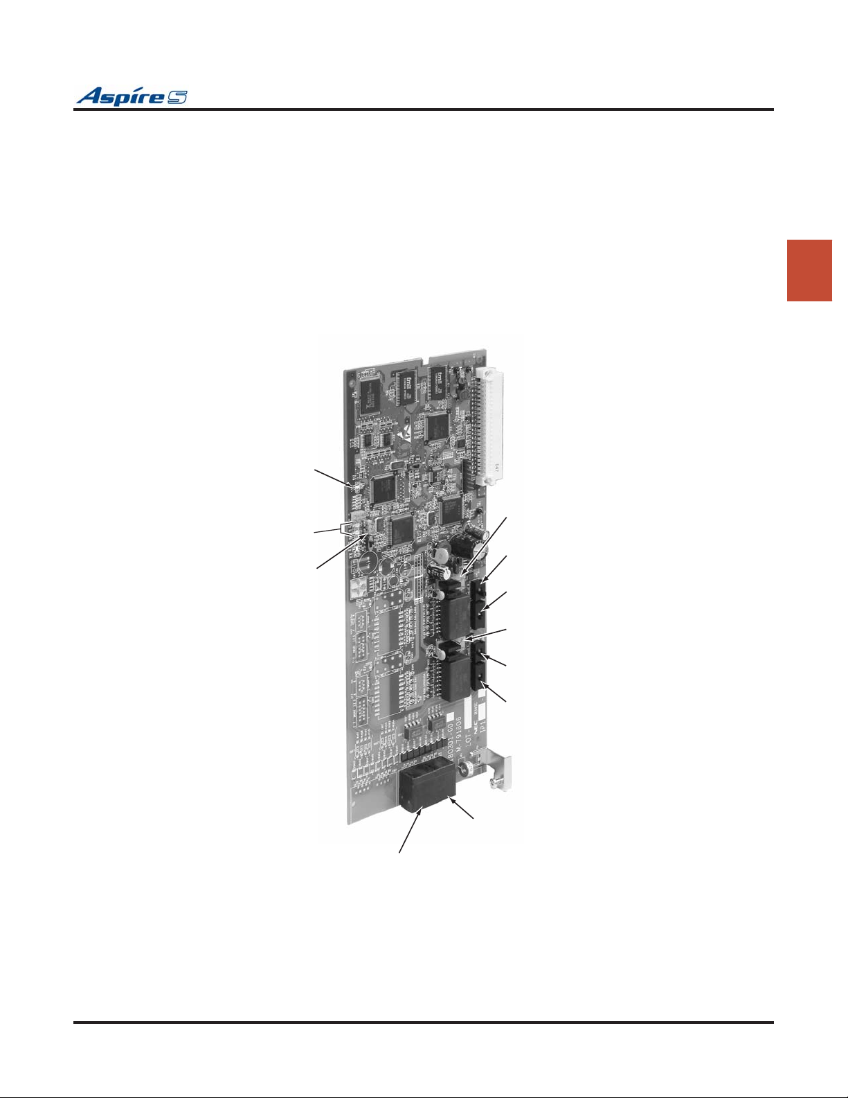
Section 2: PCB Installation and Startup
To install a BRI Interface PCB:
1. Set the SWn02 jumpers on the BRI PCB for either T-Bus or S-Bus.
2. Set the SWn00 jumpers as either terminated or unterminated.
3. Set the CNn02 jumpers to either provide power (with S-Bus) or not to supply power (with T-Bus).
4. Plug the BRI PCB into the system cabinet.
Once the system is powered up, with normal operation, the status LED will flash fast. If trouble
was found during the self diagnostics routine, the status LED will flash slow.
Once connected, the ISDN Layer Link Status LEDs will be on steady when the Layer 1 link is
established. If there is no link, the LED will be off.
5. Connect the cable from the NT1 Network Termination cable to the CN2 connector on the BRI PCB.
6. Tighten the screw on the PCB to secure the card to the cabinet.
PCB Status LED
2
LD1 - LD2
ISDN Layer
Live Status LEDs
CN8
CN102 - Power Feed
Selector for Terminal
SW100
Sets termination impedance
SW102
Selects 'T' or 'S' Bus Interface
CN202 - Power Feed
Selector for Terminal
SW200
Sets termination impedance
SW202
Selects 'T' or 'S' Bus Interface
0893130-28
CN2
RJ61 ISDN Trunk Connector
(Trunk 1)
CN2
RJ61 ISDN Trunk Connector
(Trunk 2)
Figure 2-13: BRI PCB INSTALLATION
Aspire S Hardware Manual Section 2: PCB Installation and Startup ◆ 2-31
Page 64
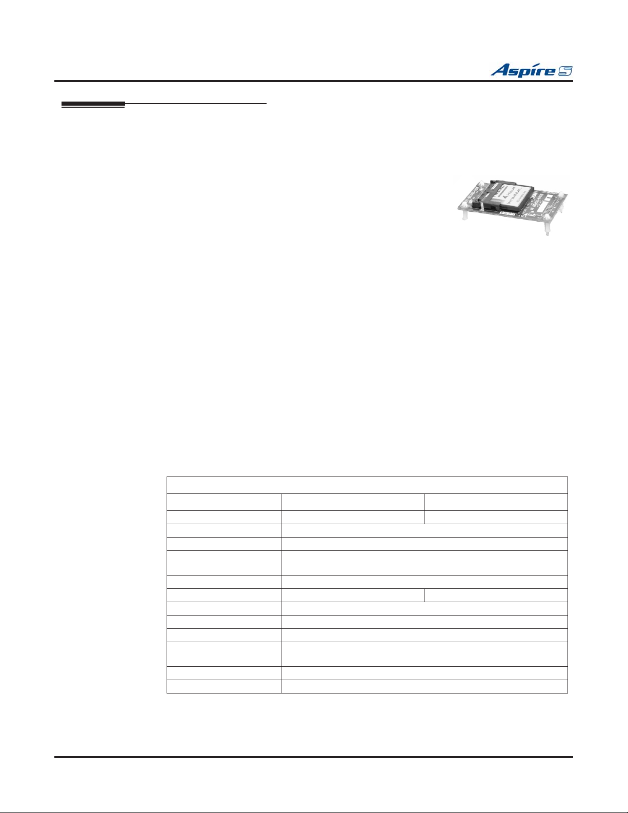
Section 2: PCB Installation and Startup
Voice Mail - IntraMail (Figure 2-14)
A DSPDB daughter board is required for either version of IntraMail.
4 Port IntraMail Compact Flash Card — P/N 0892175
The IntraMail is a plug-in “in-skin” full-featured, DSP-based integrated Voice
Mail with Automated Attendant for the Aspire S (with software 2.50 or
higher). This card is installed on the DSP Resource daughter board.
The 4 port compact flash card provides:
● 4 Voice Mail ports, 4 hours of message storage, and up to 160 mailboxes.
It requires a DSPDBU Daughter Board P/N 0891003.
The IntraMail Automated Attendant answers incoming calls and routes them quickly and efficiently. Integrated Voice Mail features include Conversation Record, Answering Machine Emulation, and Caller ID with
Return Call. Interactive Soft Keys guide the display telephone user through the extensive IntraMail feature
set. This feature is available in PCPro software 2.30 or higher.
8 Port IntraMail Compact Flash Card — P/N 0892177
The IntraMail is a plug-in “in-skin” full-featured, DSP-based integrated Voice Mail with Automated Attendant
for the Aspire S (with software 2.50 or higher). This card is installed on the DSP Resource daughter board.
The 8 port compact flash card provides:
● 8 Voice Mail ports, 8 hours of message storage, and up to 160 mailboxes.
It requires a DSPDBU Daughter Board P/N 0891003.
The IntraMail Automated Attendant answers incoming calls and routes them quickly and efficiently. Integrated Voice Mail features include Conversation Record, Answering Machine Emulation, and Caller ID with
Return Call. Interactive Soft Keys guide the display telephone user through the extensive IntraMail feature
set. This feature is available in PCPro software 2.30 or higher.
IntraMail Specifications
P/N 0892175 P/N 0892177
Ports: 4 8
Station Mailboxes: 128
Routing Mailboxes: 16
Master Mailboxes: 16
(Only 8 of the 16 Master mailboxes are accessible in Aspire S.)
Total Mailboxes: 160
Storage Hours: 4 Hours 8 Hours
Answer Tables: 8
Dial Action Tables: 16
Programming Interface: Aspire S telephone programming or Aspire PCPro software 2.30+.
Remote Programming: Access Via HTML-based Aspire WebPro or using customer-pro-
vided modems with Aspire PCPro.
Voice Storage Media: Flash Card (on IntraMail PCB)
Languages: 1 (English Mnemonic)
2-32 ◆ Section 2: PCB Installation and Startup Aspire S Hardware Manual
Page 65
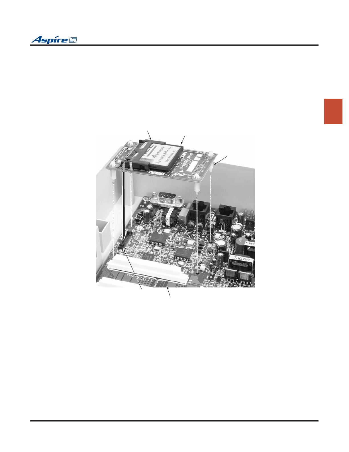
Section 2: PCB Installation and Startup
Installing an IntraMail Compact Flash Card:
The system must be powered down prior to installing the IntraMail card.
1. If not already installed, install the DSPDB daughter board. Included with the DSPDB are four spacers. Install one spacer in each corner of the daughter board. Make sure to attach the spacers from
the back of the daughter board so when installed, the compact flash slot is facing up.
2. Position the daughter board over the CN4 connector on the CPU. Push the board into the connector
on the CPU. Gently push the corners of the daughter board down so the spacers lock into the CPU.
To remove the daughter board, use pliers to squeeze the top of the spacers together, then gently
pull the daughter board off.
3. Insert the IntraMail CompactFlash card into the slot in the DSPDB.
2
0893100-165
CN4
CN1
IntraMail
Spacers
CPU
Figure 2-14: INTRAMAIL INSTALLATION
Refer to the Aspire IntraMail System Guide, P/N 0893240, for programming details.
Aspire S Hardware Manual Section 2: PCB Installation and Startup ◆ 2-33
Page 66

Section 2: PCB Installation and Startup
VoIP (VOIPU-S) PCB (Figure 2-15)
An ENTU-S PCB is required when a VoIP PCB is installed. If the ENTU-S is not installed, the
system will not start up.
The 4VOIPU-S PCB is used for converting the RTP (Real Time Transfer Protocol) packets via the IP network and PCM highway. The IP telephones are connected directly to the IP bus. When IP phones need to be
connected to a conventional PCM-based digital circuit, this PCB converts the IP packet signal into a PCM
signal format and connects to the PCM time division switch.
The VOIPU-S PCB is required in order for IP telephones to communicate with non-VoIP Aspire phones, as
well as to place or receive outside calls.
The 4VOIPU-S PCB provides:
● 4VOIPU-S PCB provides up to 4 channels
● Connector for the 4VOIPDB-S daughter board (providing an additional 4 channels)
● 1 PCB status LED
● DB status LED
● RIP session status LED
● PCMCIA slot LED
● Reset switch
● Load switch
● Boot jumper
● 1 run/block switch
A maximum of 3 PCBs per system are allowed. This provides 12 channels per system with the 4VOIPU
(with the 4VOIPDB-S, 24 channels are available).
Add the VoIP PCB after all other PCBs have been installed and the ports assigned. Otherwise, port numbering may be off as the VoIP PCB is recognized first (even before the ports on the CPU). This would mean the
VoIP is assigned ports 1-4 and the digital and analog ports on the CPU would then follow.
When installing a VoIP PCB, the 4VOIPU-S PCB uses a consecutive block of 4 trunk ports if there are 4
vacant 4 ports available. The 4VOIPU-S with a 4VOIPDB-S PCB uses a consecutive block of 8 trunk ports
if there are 8 ports available. If there are not enough trunk ports available, the VOIPU will start up without
allocating any trunk ports.
If the PCB is not going to be used for trunks, the logical trunk ports can be set to ‘0’ in Program 10-03-01 :
PCB Setup, but the physical trunk ports are still assigned to the PCB and cannot be used for any other PCB
unless the PCB is deleted from the slot in Program 90-05 : Slot Control. A maximum of 16 IP extensions
or 8 IP trunks are possible with the Aspire S. The VoIP PCB can be plugged into any universal slot.
The separate software hub should be a 100Base/full duplex hub. To avoid network problems and to ensure
good voice quality, do not use a Repeater Hub/10Base.
2-34 ◆ Section 2: PCB Installation and Startup Aspire S Hardware Manual
Page 67

Section 2: PCB Installation and Startup
PCB Port Assignments
When installing a VoIP PCB, the system automatically assigns trunk ports to match the card’s port capacity.
For example, a 4VOIPU-S would take 4 trunk ports, the 4VOIPU-S with a 4VOIPDB-S would take 8 trunk
ports. Extension ports are not reserved until an IP phone is connected to the system. When the first IP phone
is plugged in, the system takes the next four consecutive extension ports available and automatically assigns
them as IP ports. The next three IP phones installed will use this group of ports. When the fifth IP phone is
connected, the next 4 consecutive extension ports available will be assigned as IP ports.
If the number of trunk ports reserved by the system is a concern (as it could be with the Aspire S system),
install the trunk cards first, then install the VOIPU-S PCB. This will allow the trunks to be assigned to the
COIU-S, DIOPU-S, etc. first. If there are not enough trunk ports available for the VoIP PCB, the system will
still recognize the card and allow it to be used for IP phones.
Once a VoIP PCB has been installed in the system and trunks have been reserved for the PCB, the only way to
release the trunks for use by other PCBs is to remove the VoIP PCB and delete the slot (using Program 90-05).
For further details on using LAN devices, refer to Section 6: LAN Connection (page 6-1).
LED Indications
LED Function
LED1
PCB Status
LED2
DB RUN
LED3
RTP
Session
Status
LED4
PCMCIA
LED A
(On CN4)
LED B
(On CN4)
Status of PCB Green On Initializing or the Block
Status of the
4VOIPDB
Status of RTP
Session
Status of PCMCIA
Slot
Status of Link On Link is established.
Data Transmission
and Reception
LED
Status
Green
Flashing
(slow flash)
Green
Flashing
(100ms
On/Off)
Green Off Downloading or the Block
Red 4VOIPDB-S is operating
Off 4VOIPDB-S is not function-
Red RTP session is established. LED is on if one
Off RTP session is not estab-
Red PC-ATA card installed.
Off PC-ATA card not installed.
On Data is being transmitted or
Operation Status Comments
switch was set to the RUN
position.
Initialization problem
occurred during self-check.
Operating normally.
switch was set to the BLK
position.
normally.
ing correctly.
of the channels is
established.
lished.
received.
2
Aspire S Hardware Manual Section 2: PCB Installation and Startup ◆ 2-35
Page 68
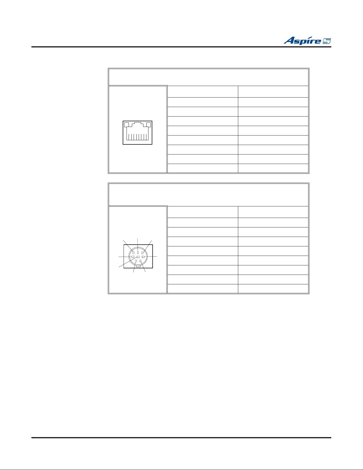
Section 2: PCB Installation and Startup
Connector Pin-Outs on VOIPU-S PCB
RJ61 Cable Connector - CN4
10Base-T / 100Base-TX Port
Pin No. Connection
1 Tx+
2 Tx-
3 Rx+
12345678
Serial Cable Connector - CN2
Serial Cross Cable with Mini-Din
(Used only for VOIPU-S PCB maintenance)
4-
5-
6 Rx-
7-
8-
Pin No. Connection
1 DCD
7
8
6
2RTS
3 RxD
4 GND
5
4
2
3
5 TxD
6 CTS
1
7 DTR
8 DSR
2-36 ◆ Section 2: PCB Installation and Startup Aspire S Hardware Manual
Page 69
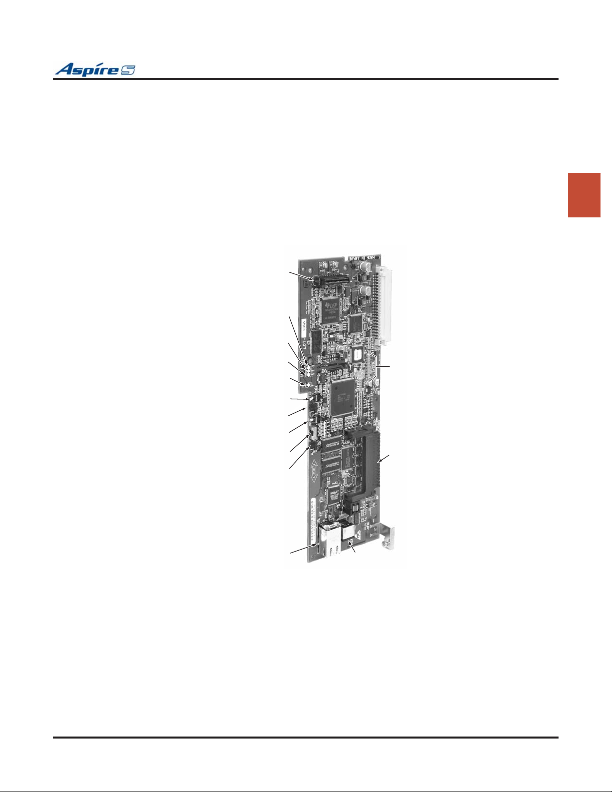
Section 2: PCB Installation and Startup
Installing the VoIP PCB:
To avoid unexpected extension/trunk numbering if the VoIP PCB registers with the system
first, install the VoIP PCB after the other types of extension/trunk PCBs have been installed.
1. Set the run/block switch DOWN.
If the VOIPDB-S is to be used, install this prior to inserting the VOIPU-S PCB into the cabinet.
Refer to VoIP (VOIPDB-S) Daughter Board (Figure 2-16) (page 2-39) for more details.
2. Install the VOIPU-S PCB into a slot.
3. Set the run/block switch
Once the system is powered up, with normal operation, the status LED will flash fast. If trouble
was found during the self diagnostics routine, the status LED will flash slowly.
4. Connect the VOIPU-S PCB to an external switching hub using an ethernet cable.
5. Tighten the screw on the PCB to secure the card to the cabinet.
6. Refer to the Aspire Software Manual (P/N 0893200) for required programming.
UP.
2
VOIPDB Connector
LED1 PCB Status LED
LED2 DB Run LED
LED3 RIP Session Status LED
LED4 PCMCIA Slot LED
SW2 Reset Switch
SW1 Load Switch
SW3 Run/Block Switch
JP1 Boot Jumper
CN4 LAN Interface
CN11
Load Jumper
Connector
LED A [left] and
Act LED B [right]
CN6
CN14
PCMCIA
0893130-26
CN2
Serial Connector
Figure 2-15: VOIPU-S PCB INSTALLATION
Aspire S Hardware Manual Section 2: PCB Installation and Startup ◆ 2-37
Page 70

Section 2: PCB Installation and Startup
Upgrading Your VOIPU-S Firmware
1. Copy the updated firmware file (VoIPU.bin) to the compact flash card.
2. Power down the system.
3. Insert the CF (compact flash) card into the VOIPU-S PCB’s CN14 slot.
4. Move the Load jumper (JP6) to pins 2-3.
5. Insert the PCB into the cabinet.
6. Power up the system.
7. Remove the CF card once the status LED1 on the VOIPU-S PCB starts flashing green.
8. Set the Load jumper (JP6) back to pins 1-2.
OR
Using an RS232 Connection:
1. Copy the updated firmware file (VoIPU.bin) to the compact flash card.
2. Power down the system.
3. Connect a PC to the serial connector (CN1) on the Aspire S using an RS232 cross cable.
4. Open HyperTerminal on the PC.
The settings for the HyperTerminal session should be:
Baud Rate: 38400, Data Bit: 8, Non Parity, Stop Bit: 1
5. Set the SW3 switch on the Aspire S CPU to the “6” side.
6. Insert the CF (compact flash) card into the VOIPU-S PCB’s CN14 slot.
7. Move the Load jumper (JP6) to pins 2-3.
8. Insert the PCB into the cabinet.
9. Power up the system.
10. Remove the CF card once the status LED1 on the VOIPU-S PCB starts flashing green.
11. Enter “slot info x” (x=the slot number) from HyperTerminal.
12. Confirm the version number.
13. Set the Load jumper (JP6) back to pins 1-2.
14. Set the SW3 switch on the Aspire S to the “4” side.
2-38 ◆ Section 2: PCB Installation and Startup Aspire S Hardware Manual
Page 71
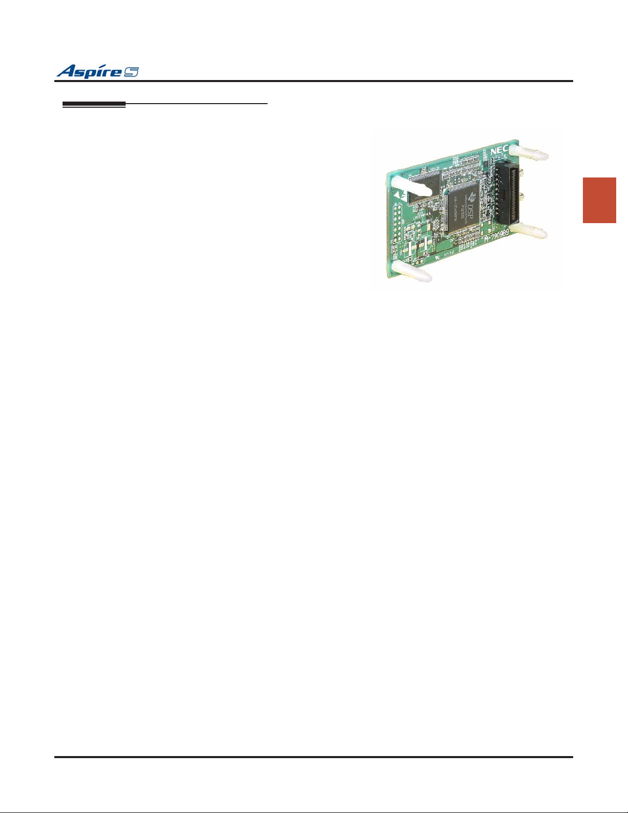
Section 2: PCB Installation and Startup
VoIP (VOIPDB-S) Daughter Board (Figure 2-16)
The 4VOIPDB-S daughter board provides:
● 4 channels
● Connector for the 4VOIPU-S PCB (combination
provides a maximum of 8 channels per slot)
The VOIPDB-S is installed on the VOIPU-S PCB with
a maximum of 3 daughter boards per system. This provides a maximum of 24 channels when combining the
4VOIPU-S and 4VOIPDB-S.
When installing a 4VOIPU-S with a 4VOIPDB-S PCB,
the system uses a consecutive block of 8 trunk ports if
there are 8 ports available. If there are not enough trunk
ports available, the VOIPU will start up without allocating any trunk ports.
If the PCB is not going to be used for trunks, the logical
trunk ports can be set to ‘0’ in Program 10-03-01 :
PCB Setup, but the physical trunk ports are still assigned to the PCB and cannot be used for any other PCB
unless the PCB is deleted from the slot in Program 90-05 : Slot Control.
2
Figure 2-16: VOIPDB
Refer to PCB Port Assignments on page 2-35 for details on the port usage with the VOIPDB-S. For further
details on using LAN devices, refer to Section 6: LAN Connection (page 6-1).
Installing an VOIPDB-S Daughter Board:
1. Included with the VOIPDB-S are four plastic spacers. These are installed in each of the four corners
of the daughter board. Make sure to attach the spacers on the front of the daughter board so when
installed, the components are facing the VOIPU-S PCB.
2. Position the VOIPDB-S’s CN6 connector over the CN11 connector on the VOIPU-S PCB. Press the
boards together, ensuring the plastic spacers lock in place.
3. Install the VOIPU-S PCB into the slot.
4. Refer to VoIP Feature Supplement (P/N 0893204) for required programming.
Aspire S Hardware Manual Section 2: PCB Installation and Startup ◆ 2-39
Page 72

Section 2: PCB Installation and Startup
SYSTEM STARTUP
System Startup
You can now power up the system and briefly check its operation. Before proceeding, be sure that:
● The common equipment is installed correctly.
● All extensions are cabled correctly.
● All earth ground and telco connections are installed correctly.
● PCBs are configured, equipped, and strapped correctly.
Powering Up the System
To avoid unexpected extension/trunk numbering if the VoIP PCB registers with the system
first, install the VoIP PCB after the other types of extension/trunk PCBs have been installed.
When powering the system up or down, wait 10 seconds before pressing the button again. This
allows the system to complete the startup/shutdown process.
1. Install all the required PCBs into the system cabinet.
2. Plug in all system telephones. A display telephone should be plugged into port 01 (extension 301).
3. Plug in the AC power cord for the cabinet into its surge protector.
4. When starting the system f
power button ON. After approximately 3 seconds, release the LOAD button.
This performs a cold start (defaults all program entries) on the Aspire system to make sure
you’re starting with a defaulted system.
When po
Refer to Switch Settings and LED Indications on page 2-8 for CPU LED status.
5. Wait about two minutes for the system to boot. The telephone display at extension 301 will show
the Time/Date and extension number when the boot sequence completes.
wering up any other time, simply press the power supply’s AC power button.
or the first time, hold the LOAD button on the CPU and turn the AC
Note: Refer to TROUBLESHOOTING (page 3-16) if the system does not boot.
The system will automatically recognize each PCB installed in the system. If a PCB has previously been
installed in a slot and another type of PCB is to be installed in that same slot, the PCB must be first be
removed from the cabinet and then the slot definition removed using Program 90-05 prior to installing the
new PCB.
This same condition applies to extensions and other devices connected to the system. For example, if a port
was previously used for a keyset and a DSS Console is to be installed in that same port, it must first be undefined in Program 10-03 before the console is connected.
For more information on Cold and Hot system starts, refer to Central Processing Unit (CPU) PCB (Figure
2-3) (page 2-6).
Whenever powering down the system, check to make sure the only LED flashing on the CPU card itself is the
LD2 LED (farthest right of the LEDs). This LED is located in the lower left-hand corner of the CPU. If any
other LEDs are flashing on the CPU, wait until they stop or else the system data may be corrupted.
2-40 ◆ Section 2: PCB Installation and Startup Aspire S Hardware Manual
Page 73
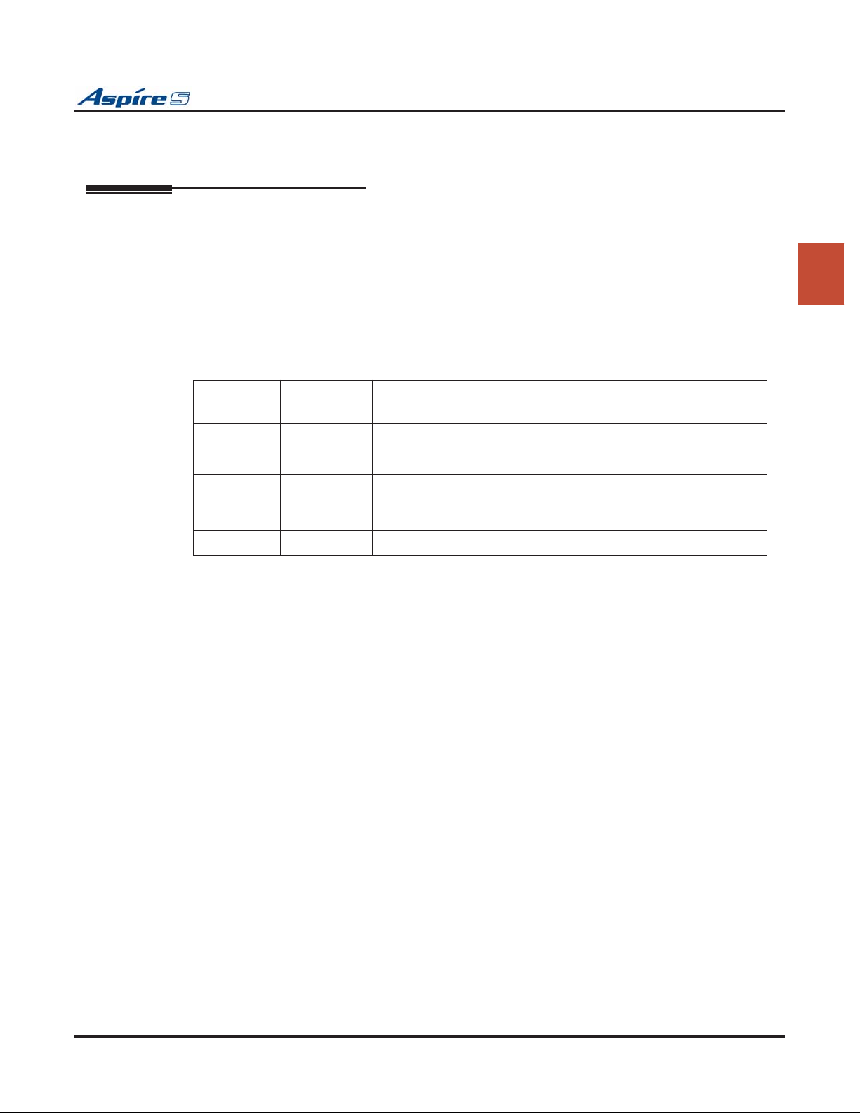
PCB STARTUP
Initial PCB Installation
first, install the VoIP PCB after the other types of extension/trunk PCBs have been installed.
Section 2: PCB Installation and Startup
To avoid unexpected extension/trunk numbering if the VoIP PCB registers with the system
The order in which SLIU-S and ESIU-S PCBs are physically inserted determines the numbering plan.
The installer must install extension PCBs in order (i.e.; slot 3 first, slot 4 next, etc.) for a sequential numbering plan.
For example, as the CPU provides 8 digital station ports (ext. 301-308), when 2 more station cards are
installed in the following order, the numbering plan below would apply:
Order of
Install
1 CPU --- 301-308 (digital extensions)
2 CPU --- 309-310 (analog extensions)
3 3 4SLIU-S
4 4 8ESIU-S 319-326
Refer to PCB Port Assignments on page 2-35 for details on the port usage with the VOIPU-S PCB and
VOIPDB-S. As these cards are assigned trunk ports when initially installed, this could impact the number of
ports available for extensions.
PCB Slot # PCB Extension Numbers
311-318
(with the 4SLIDB-S daughter
board)
2
Aspire S Hardware Manual Section 2: PCB Installation and Startup ◆ 2-41
Page 74
Section 2: PCB Installation and Startup
Initial Programming (Figure 2-17)
The system can be programmed using the following methods:
● Through a digital keyset
● Web Programming
Refer to the PCPro/WebPro Installation Manual, P/N 0893201, for complete installation details.
Refer to the Aspire Software Manual (P/N 083200) for complete details on programming.
Entering the Programming Mode
Enter the system programming mode at extension 301:
1. Press CALL1. (You hear dial tone).
2. Dial # * # *.
3. Dial the system password.
Password Level
12345678 2 (IN)
0000 3 (SA)
9999 4 (SB)
4. Press HOLD.
Port Defaults
With the default settings, the ports are assigned as follows:
Making Test Calls
In the initial configuration:
● All Programmable Function keys are line keys (e.g., key 1 is line 1).
● All trunks are loop start DTMF.
Station Ports: 1-26 (extensions 301-499 and 5000-5312)
Virtual Station Ports: 1-24 (extensions not assigned)
Trunk Ports: 1-8
2-42 ◆ Section 2: PCB Installation and Startup Aspire S Hardware Manual
Page 75
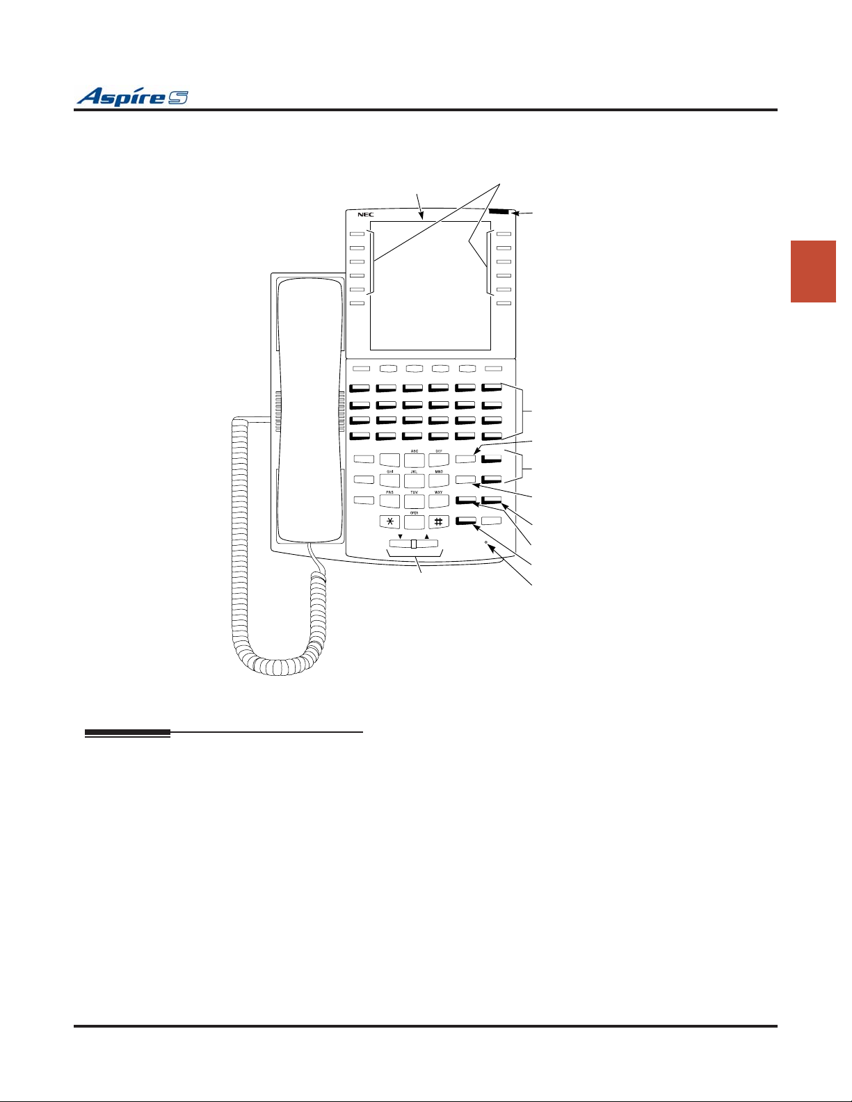
Section 2: PCB Installation and Startup
0893200 - 2
Soft Keys
Alphanumeric
Display
SERVICE
RINGING
MENU 1
CHECK
12 3 4 5 6
78 9101112
13 14 15 16 17 18
19 20 21 22 23 24
MSG
1
FLASH
CONF
2
5
4
8
7
0
VOL
Handsfree,
Handset,
Page and BGM
Volume Control
MENU 2
CLEAR
CALL 1
DIAL
3
LND
6
9
CALL 2
DND
MIC
SPK
HOLD
guide you through your
features. While your phone is
idle, the Soft Keys are normal
One Touch Keys.
Message Waiting
Lamp
Programmable
Function Keys
Abbreviated
Dialing
Dual Line
Appearance Keys
Last Number
Redial
Do Not Disturb
Microphone Cutoff
Speakerphone
Microphone
2
Figure 2-17: TELEPHONE KEY LAYOUT
Setting Up Extension Circuit Types
Run Program 10-03 to set up extension circuit types as required. The system will automatically detect and
assign most circuit types when the device is connected. Refer to the Software Manual for programming
information.
1. Dial 10-03-01.
2. Select the slot, port or channel (with ESIU-S PCBs) to be programmed by pressing FLASH.
3. Set the terminal type or option as needed.
Refer to the Software Manual for this information.
If the system has DSS Consoles, Program 30-02 must be used to define DSS extension assignments.
As the system recognizes the extension devices automatically, when replacing the type of device connected,
the type must be undefined in Program 10-03 prior to connecting the new device. For example, if a port was
previously used for a keyset and a DSS Console is to be installed in that same port, it must first be undefined
in Program 10-03 before the console is connected.
Aspire S Hardware Manual Section 2: PCB Installation and Startup ◆ 2-43
Page 76

Section 2: PCB Installation and Startup
Saving Your Configuration
When you are done programming, you must be out of a program’s options to exit (pressing the MSG key
will exit the program’s option). Press the SPK key. Any changes made will be saved to the CPU.
1. Press MSG key to exit the program’s options, if needed.
2. Press SPK. You see, "Saving System Data" if changes were made to the system’s programming.
3. The display shows "Complete Data Save" when completed and will exit the phone to an idle mode.
Backing Up/Restoring a Database
Due to database differences, saved customer databases are not interchangeable between the
Aspire S and Aspire systems. The PCPro will prevent the upload of an incorrect database by disabling the Upload button when the system database does not match the system to which you are
connected. However, when using Program 90-04 : Load Data, the system will not be able to prevent an incorrect upload. It is important to make sure you only load data saved from an Aspire S to
an Aspire S system and data saved from an Aspire to an Aspire system.
As a precaution for existing systems which have already been programmed, it is recommended that the customer database be saved prior to updating the system software. There are two methods of saving the database
- either using the PCPro application or saving directly to a blank 32 meg CompactFlash card. Using PCPro,
download the database and save the file on the PC’s hard drive. To save the database using a blank 32 meg
compact flash card (P/N 0891064), insert the card into the CPU and, using Program 90-03, save the software. Due to the file’s naming structure, note that a compact flash card can only hold one customer database
(each database is saved to a directory called DATA - this directory would be overwritten if a second database
were saved to the same card). Each database to be saved will require its own separate card (unless you
choose to rename the directory after it is saved, then rename it back to DATA when you need to access the
database).
If the customer data needs to be reloaded, the method for restoring the database is determined by how the
database was saved. Using PCPro, the customer database is uploaded using the Upload option within the
application. If the database is stored on a CompactFlash card, use Program 90-04, with the database to be
restored installed in the CPU.
When restoring a database file, as the slot definitions may be different, remove all PCBs from
the system. After the system has been reset, you can reinstall the PCBs. You can use Program 10-03
or Program 90-13-03 prior to updating to record the current slot definitions. If the PCBs are not
removed, the trunk and extension port assignments may be reassigned, depending on which PCB
syncs up with the system first.
After reloading the customer data to the system, exit programming mode (this could take a minute or more
to save the database), then r
all the uploaded programming changes will be in effect. Wait a few minutes for the programming to take
affect before accessing any lines or special system features. Otherwise some unusual LED indications may
be experienced. To prevent the CompactFlash card from possibly being over-written, remove the card after
reloading the database.
When restoring a database file, as the slot definitions may be different, remove all PCBs from
the system. After the system has been reset, you can power down the system and then reinstall the
PCBs. You can use Program 10-03 or Program 90-13-03 prior to updating to record the current slot
definitions. If the PCBs are not removed, the trunk and extension port assignments may be reassigned, depending on which PCB syncs up with the system first.
eset the system by powering down and back up. If the system is not reset, not
2-44 ◆ Section 2: PCB Installation and Startup Aspire S Hardware Manual
Page 77

Section 2: PCB Installation and Startup
Using Flash Cards for System Software
As the Aspire S system uses a compact flash card for software upgrades, it is possible to receive or download
a compressed file from NEC containing the system software. The following information details the steps
required to update the system software using a pre-programmed CompactFlash card containing system software or when the software is received as a compressed file.
Using a Compressed File for System Upgrades
ements
Requir
● Customer Provided: CompactFlash Card Reader OR a PCMCIA Slot in a Laptop with a
CompactFlash Adapter
Suggestions:
Readers: Kingston USB 2.0 Hi-Speed PC Card Reader (model FCR-HS2/ATA)
SimpleTech FlashLink CompactFlash Type I and II Card USB Reader
(model STI-UCF100)
SimpleTech FlashLink All-In-One USB Reader (model STI-UMC600)
Adapters: SimpleTech CompactFlash Adapter for Type II PC Card Slots
(model STI-CFAD) (accommodates CompactFlash Type 1 cards)
SanDisk CompactFlash PC Card Adapter (model SDCF-38)
(accommodates CompactFlash Type 1 cards)
● Customer Provided: Two 32MB CompactFlash Cards (1 for system software, 1 for database backup)
● Aspire S System Software Zip File
● WinZip application
This program can be downloaded from WinZip’s web site: http://www.winzip.com
2
1. After receiving the compressed system software file from NEC, it must be unzipped using the WinZip
application.
If the file was received by EMail, detach the zip file to your computer.
2. Locate the zip file on your computer and double-click on the file.
The file opens the WinZip application and displays a list of the compressed files.
3. Click ACTIONS - EXTRACT or click the EXTRACT button on the tool bar.
4. In the Extract window that appears, make sure the USE FOLDER NAMES options is checked. This is
required to keep the proper paths for the files as they are extracted.
5. Select the location to which the files should be extracted and click the EXTRACT button.
Suggestion: You may want to create a directory in which all Aspire software can be kept (with a
sub-directory for the version type - example: Aspire_Software/2_03). This allows you to keep the
original source files for future use, if required.
6. Place the compact flash card to be used for the update into the compact flash card reader.
7. Double-click on MY COMPUTER and then double-click on the compact flash card reader.
The contents of the compact flash card should be displayed.
8. If there are any existing files on the compact flash card, delete or move any files off the card before proceeding.
9. Open the directory containing the system software files to be used for the system update.
10. Select all the files within the folder and copy them to the flash card.
This can be done as follows:
- From the software directory window, click: Edit - Select All - Edit - Copy
- From the flash card window, click Edit - Paste
The files are then copied from the PC to the CompactFlash card.
Continue by updating the system software using the procedure detailed in the Upgrading Soft-
ware on page 2-46 instructions.
Aspire S Hardware Manual Section 2: PCB Installation and Startup ◆ 2-45
Page 78

Section 2: PCB Installation and Startup
Upgrading Software
When initially updating your Aspire S to 2.50 or higher, refer to Upgrading Software From
Version 2.0x, 2.1x, or 2.2x to 2.50 or Higher on page 2-47.
Requir
● 32MB CompactFlash Card containing Aspire S System Software (pre-programmed or from an
ements
extracted zip file)
Refer to Using a Compressed File for System Upgrades on page 2-45 if the software was
received as a Zip file.
! Important !
As a precaution, it is recommended that the customer database be saved prior to updating the
system software. Refer to Backing Up/Restoring a Database (page 2-44).
1. If previously powered up, the system must be turned off for upgrading software. Before powering
down the system, verify that of the 4 LEDs in the lower left corner of the CPU, only LD2 is flashing
(this LED is located farthest right of the LEDs). If any other LEDs are flashing, wait until they stop
before proceeding.
Turning off the power when other LEDs are flashing may corrupt the system data.
2. Turn the system power off by pressing the power switch to OFF
3. Once the system has completed its powering down cycle (all LEDs are off), insert the CompactFlash
card containing the software upgrade into the CompactFlash card slot (CN5) on the CPU.
4. Push in and hold the Load button.
5. Turn the system power on by pressing the power button to power the system back up.
6. Continue holding the Load button for approximately 10 seconds.
7. Release the Load button.
8. Wait until the Status LEDs on the CPU have the following indications (approximately 2 minutes):
LD1: Flashing Red, LD3: Flashing Red, LD4: Flashing Red, LD2: Steady Green.
9. Turn the system power off by pressing the power button on the cabinet.
10. Once the system has completed its powering down cycle (all LEDs are off), remove the CompactFlash
card.
11. Turn the system power back on.
12. When the system has completed reloading the software, LD2 will begin flashing on the CPU. The
remaining 3 LEDs will now be off.
To confirm the new software version has been installed, the system version number can be
viewed by pressing CHECK and then the HOLD key on any display keyset. This can also be confirmed in Program 90-16-01.
The existing system software in the flash memory is replaced, but the customer data (stored in
the RAM) is saved.
It is important to remember that the PCB installation must be done with the system powered
down.
2-46 ◆ Section 2: PCB Installation and Startup Aspire S Hardware Manual
Page 79

Section 2: PCB Installation and Startup
Upgrading Software From Version 2.0x, 2.1x, or 2.2x to 2.50 or Higher
Due to the port capacity changes in 2.50 software, it is recommended the system be cold started and the customer database reprogrammed. However, using PCPro 3.00 or higher, you can choose to reload the majority
of the customer database using the steps below.
Use the following steps to update your Aspire S with 2.0x, 2.1x, or 2.2x software to 2.50 or higher. This process is only required to bring the system up to 2.50 or higher. Once the system has been updated to this level,
any future software upgrades should follow the instructions indicated Upgrading Software on page 2-46. If
the following steps are not used when upgrading to 2.50 or higher, the IntraMail feature will not function
correctly.
1. As a precaution, it is recommended that the customer database be saved prior to updating the system
software. Refer to Backing Up/Restoring a Database (page 2-44).
2. Set Program 45-01-01 : Voice Mail Integration Options, Voice Mail Department Group Number
to “0” (no voice mail).
This could prevent IntraMail from automatically configuring correctly.
3. In Program 16-02-01 : Department Group Assignment for Extensions, make sure there are no
extension ports assigned to Department Group 8.
This could prevent IntraMail from automatically configuring correctly.
4. Upgrade the system software to version 2.50 or higher.
a. Before powering down the system, verify that of the 4 LEDs in the lower left corner of the CPU,
only LD2 is flashing (this LED is located farthest right of the LEDs). If any other LEDs are flash-
ing, wait until they stop before proceeding.
Turning off the power when other LEDs are flashing may corrupt the system data.
b. Turn the system power off by pressing the power switch to OFF.
c. Once the system has completed its powering down cycle (all LEDs are off), insert the Compact-
Flash card containing the software upgrade into the CompactFlash card slot (CN5) on the CPU.
d. Push in and hold the Load button.
e. Turn the system power on by pressing the power button to ON.
f. Continue holding the Load button for approximately 10 seconds.
g. Release the Load button.
h. Wait until the Status LEDs on the CPU have the following indications (approximately 2 min-
utes):
LD1: Flashing Red, LD3: Flashing Red, LD4: Flashing Red, LD2: Steady Green.
i. Power down the system and remove the CompactFlash card.
j. Power the system back up.
5. Confirm the new software version has been installed by pressing CHECK and then the HOLD key on
any display keyset. This can also be confirmed in Program 90-16-01.
6. Connect to the Aspire S system using PCPro software 2.30 or higher then download and save the customer database from the system.
a. Open PCPro.
b. Click FILE - NEW - ASPIRE S.
c. Click COMMUNICATIONS - CONNECT. Enter the user name, password, and IP address
required for the Aspire S. Click CONNECT.
d. Click COMMUNICATIONS - DOWNLOAD - Select Range should show ALL - Click
START.
e. When complete, click CLOSE then click FILE - SAVE AS - Save the database file.
f. Disconnect from the system by clicking COMMUNICATIONS - DISCONNECT.
7. Power the system down.
8. Once the system has completed its powering down cycle (all LEDs are off), remove all installed PCBs.
9. Install the IntraMail CompactFlash card into the DSPDBU and install the daughter board onto the
CPU.
2
Aspire S Hardware Manual Section 2: PCB Installation and Startup ◆ 2-47
Page 80

Section 2: PCB Installation and Startup
10. Perform a Cold Start.
a. Push in and hold the Load button.
b. Power the system back up.
c. Continue holding the Load button for approximately 3 seconds.
d. Release the Load button.
e. Allow the system to completely reload the software (approximately 2 minutes). The Status LED
(LD2) will be flashing on the CPU.
11. Reconnect to the system with PCPro and reload the database saved in Step 6 EXCEPT FOR PRO-
GRAMS 16-02, 11-07, 45-01, and all 47-xx. Downloading the complete database will cause problems with the IntraMail programing.
a. Click COMMUNICATIONS - UPLOAD.
b. Under the SELECT RANGE drop-down box, select SYSTEM CONFIGURATION and click
START.
c. Once that upload is complete, under the SELECT RANGE drop-down box, select SYSTEM
DATA. While holding down the CTRL key, scroll to each program which should not be downloaded (11-07, 45-01, and all the 47-xx programs) and click to deselect. Click START
d. Once that upload is complete, under the SELECT RANGE drop-down box, select TELE-
PHONE DATA. While holding down the CTRL key, scroll to Program 16-02 and click to deselect. Click START
e. Once that upload is complete, under the SELECT RANGE drop-down box, select VE DATA
and click START.
A screen may appear indicating there is no data to upload. Simply click OK and continue
with the next upload.
f. Once that upload is complete, under the SELECT RANGE drop-down box, select TRUNK
DATA and click START.
g. Click CLOSE.
12. Click COMMUNICATIONS - DISCONNECT to exit system programming.
Exiting programming mode could take a minute or more while it saves the database.
13. Wait until the Status LEDs on the CPU have the following indications (approximately 2 minutes), then
power the system down.
LD1: Flashing Red, LD3: Flashing Red, LD4: Flashing Red, LD2: Steady Green.
14. Reinstall the PCBs removed in Step 8.
15. Turn the system power back on.
Refer to the Aspire IntraMail System Guide, Chapter 1 - Quick Setup (P/N 0893240) for
details on programming the IntraMail feature.
2-48 ◆ Section 2: PCB Installation and Startup Aspire S Hardware Manual
Page 81
Identifying Port Location
Port information such as PCB type, port numbers, PCB status, and individual port status can be obtained
from the system. To obtain a System Report containing PCB information, the system must be connected to a
PC or terminal using the serial port connector on the CPU.
Running program 90-13-03 in MAINTENANCE PROGRAMS prints a system PCB report. Refer to Pro-
gram 90-13-03 : System Information Output in the Software Manual. The following is a typical report:
Section 2: PCB Installation and Startup
<<SYSTEM INFORMATION>> 011/03/03 09:49
slot location type assign port condition note
1 1-1 ESIU 1- 8 Running ****---- -------- Connect:*
2 1-2 SLIU 9- 10 Running
3 1-3 ESIU 11- 18 Running
4 1-4 SLIU 19- 26 Running
5 1-5 COIU 1- 4 Running
6 1-6 DIOPU 5- 6 Not Install
7 1-7 - none -
8 1-8 - none -
9 2-1 - none -
10 2-2 - none -
11 2-3 - none -
12 2-4 - none -
13 2-5 - none -
14 2-6 - none -
15 2-7 - none -
16 2-8 - none -
2
Aspire S Hardware Manual Section 2: PCB Installation and Startup ◆ 2-49
Page 82

Section 2: PCB Installation and Startup
- For Your Notes -
2-50 ◆ Section 2: PCB Installation and Startup Aspire S Hardware Manual
Page 83
Section 3: Installing Extensions and Trunks
Section 3:
Installing Extensions
Section 3: Installing Extensions and Trunks
!! Important !!
Install telephones as on-premise extensions only. (Otherwise, the telephones are highly
susceptible to lightning strikes.)
RJ-61 TO 66 BLOCK CONNECTIONS
Wiring RJ-61 Cables to 66 Blocks
When not using a 25-pair amphenol cable to connect extensions or trunks, use the following pin information
for the RJ-61 connector to connect your cables to the 66 blocks.
66 Block RJ-61 Connector
Block Termination 1: WHT-BLU Pin 5
and Trunks
3
Block Termination 2: BLU-WHT Pin 4
Block Termination 3: WHT-ORN Pin 3
Block Termination 4: ORN-WHT Pin 6
Block Termination 5: WHT-GRN Pin 2
Block Termination 6: GRN-WHT Pin 7
Block Termination 7: WHT-BRN Pin 1
Block Termination 8: BRN-WHT Pin 8
Aspire S Hardware Manual Section 3: Installing Extensions and Trunks ◆ 3-1
12345678
Page 84

Section 3: Installing Extensions and Trunks
INSTALLING 25-PAIR CABLES
Routing Cables
It is recommended to install extension blocks to the left of the cabinet. The trunk blocks can then be installed
to the right of the cabinet. Run the 25-pair cable from the extension block and from the trunk block through
the cable pass-throughs on either side of the cabinet.
Installing Extension Cross-Connect Blocks
It is also recommended to install cross-connect blocks for each of the system's major extension port device
groups. Cross-connect blocks provide an easy way to troubleshoot, determine port identification numerically, and determine port utilization.
Install cross-connect blocks for the following interfaces:
● All digital extension circuits
● CPU functions (i.e.; BGM, MOH, General Purpose Control Relay)
● External page
● External alarms
● Data devices
Installing Trunk Cross-Connect Blocks
It is also recommended to install cross-connect blocks for each of the system's major trunk device groups.
Cross-connect blocks provide an easy way to troubleshoot, determine port identification numerically, and
determine trunk port utilization.
Install cross-connect from telco’s RJ21X to the trunk cross-connect blocks for the following:
● analog loop start lines
● DID trunks
3-2 ◆ Section 3: Installing Extensions and Trunks Aspire S Hardware Manual
Page 85
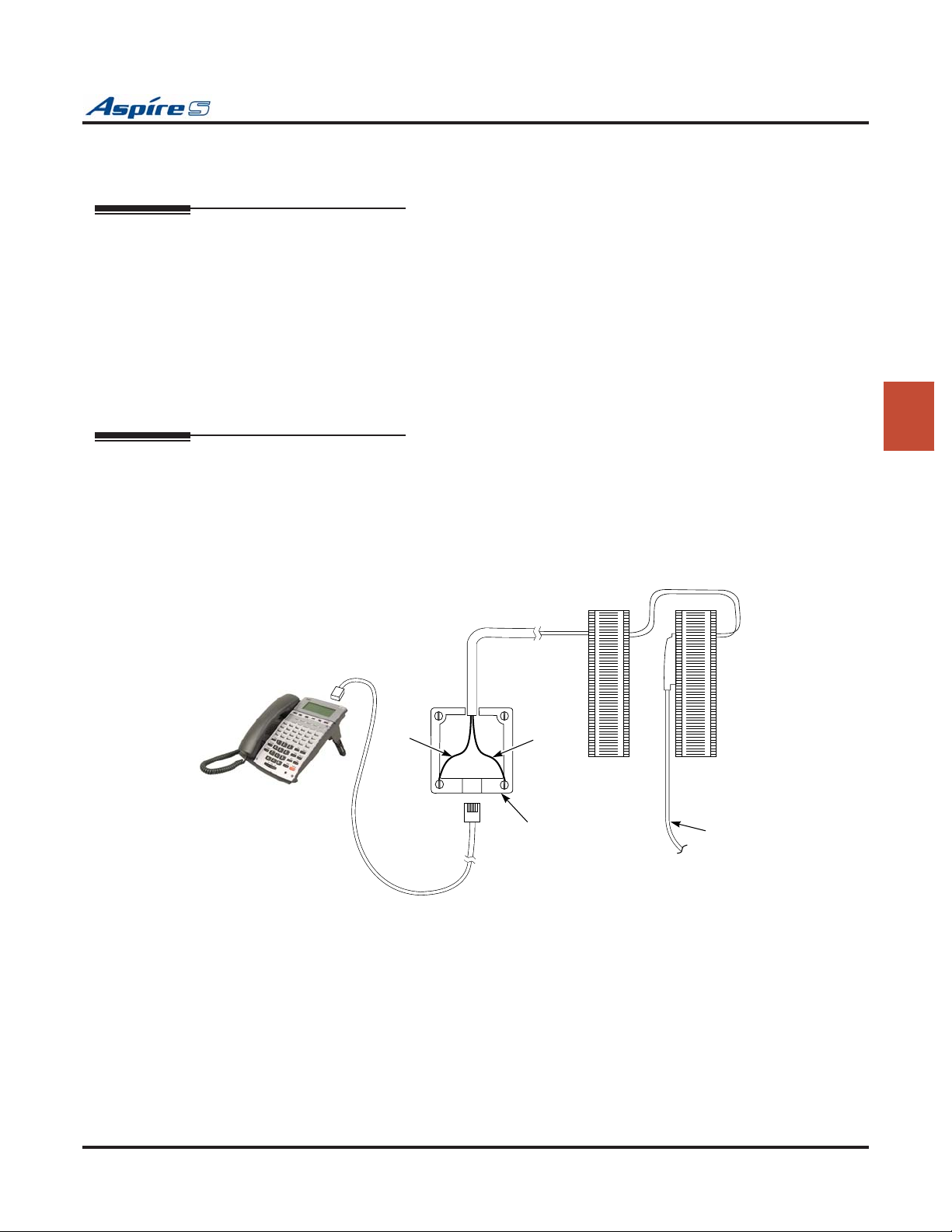
Section 3: Installing Extensions and Trunks
INSTALLING EXTENSIONS
Key Extension Cabling (Figure 3-1)
Each key extension requires one-pair twisted station cable from the MDF to the modular jack. A maximum
of 24 2-wire extensions can be installed per 50-pin block.
To connect key station cabling:
1. Punch down one pair 24 AWG station cable for each key telephone to a cross-connect block.
2. Run one-pair cross-connect from the cross-connect block to the extension (B) block for each extension.
3. Connect the extension (B) block's 25-pair cable to the corresponding RJ-61 connector on the PCB.
4. Install bridging clips on the extension (B) block.
Installing a Key Telephone (Figure 3-1)
1. Install a modular jack for each extension. The modular jack should be within six feet of the phone.
2. For each extension, run one-pair 24 AWG station cable from the cross-connect block to a modular
jack. Ground the unused pair.
3. Terminate the extension leads to GRN/RED of the modular jack. Terminate the unused leads to the
jack.
3
YEL
BLU-WHT
0893100-92
RED
Figure 3-1: INSTALLING A KEY TELEPHONE
BLK
WHT-BLU
GRN
625
Modular
Jack
Cross
Connect
Block
"B"
Block
25-pair
cable to
extension
PCB
Aspire S Hardware Manual Section 3: Installing Extensions and Trunks ◆ 3-3
Page 86
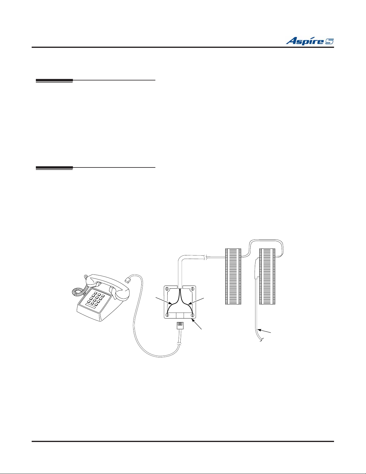
Section 3: Installing Extensions and Trunks
INSTALLING SINGLE LINE TELEPHONES
Single Line Extension Cabling (Figure 3-2)
Each single line extension requires one-pair twisted station cable from the MDF to the modular jack. A maximum of 24 2-wire extensions can be installed per 50-pin 66 block.
To connect station cabling:
1. Punch down one pair 24 AWG station cable for each single line telephone to a cross-connect block.
2. Punch down cross-connect from the clips on the cross-connect block to their corresponding clips on
the extension (B) block.
3. Connect the extension (B) block's 25-pair cable to the corresponding RJ-61 connector on the PCB.
4. Install bridging clips on the extension (B) block.
Installing a Single Line Telephone (Figure 3-2)
To install a single line telephone:
1. Install a modular jack for each single line telephone. The modular jack should be within six feet of
the phone.
2. For each extension, run one-pair 24 AWG station cable from the cross-connect block to a modular
jack.
3. Terminate the extension leads to GRN/RED of the modular jack. Terminate the unused leads to the
jack.
BLK
WHT-BLU
GRN
625
Modular
Jack
Cross
Connect
Block
"B"
Block
25-pair
cable to
extension
PCB
0893100-93
YEL
BLU-WHT
RED
Figure 3-2: INSTALLING A SINGLE LINE TELEPHONE
3-4 ◆ Section 3: Installing Extensions and Trunks Aspire S Hardware Manual
Page 87
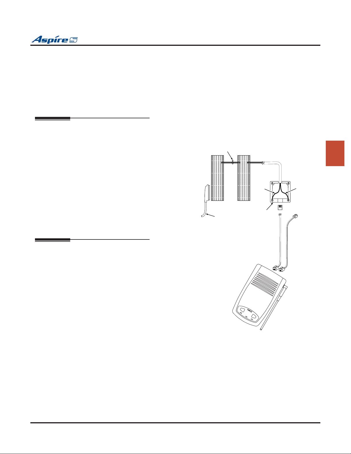
Section 3: Installing Extensions and Trunks
E
INSTALLING CORDLESS TELEPHONES
The Cordless Lite II/Cordless II phone allows for the connection of an optional keyset phone. The base unit
allows the user to switch between the Cordless Lite II/Cordless II phone and an Aspire keyset. Whichever
phone is activated at the base unit is the telephone which will ring. This allows you to have a keyset phone to
use while at your desk, and when you need to be away from your desk, you can carry the cordless phone
with you. Refer to Cordless Telephone — P/N 730088/730087 (page 4-64) for more details on setting up
the phone and its optional equipment.
Cordless Phone Extension Cabling (Figure 3-3)
Each cordless phone extension requires a digital extension port with one-pair twisted station cable from the
MDF to the modular jack.
To connect station cabling:
1. Punch down one-pair 24 AWG station cable
for each cordless telephone to a cross-connect block.
2. Punch down cross-connect from the clips on
the cross-connect block to their corresponding clips on the extension (B) block.
3. Connect the extension (B) block's 25-pair
cable to the corresponding RJ-61 connector
on the PCB.
4. Install bridging clips on the extension (B)
block.
One Pair
Cross Connect
730082-1
"B" Block
25-Pair Station
Cable to CEU
Telco
RJ21X
BLU-WHT
625
Modular
Jack
RED
3
YEL
BLK
WHT-BLU
GRN
To
Optional
Aspire Keyset
Installing a Cordless Telephone (Figure 3-3)
To install a cordless telephone:
1. Install a modular jack for each cordless telephone. The modular jack should be within
six feet of the base unit.
2. For each extension, run one-pair 24 AWG
station cable from the cross-connect block to
a modular jack.
3. Terminate the extension leads to GRN/RED
of the modular jack.
Important
In some cases, when testing the operation of an extension port when connecting to a Cordless II, Cordless
Lite II, or 2PGDAD module, a technician may connect a line cord directly from an extension port on the Aspire/Aspire S ESIU PCB or Aspire S CPU. Though
this is not the recommended connection, it can be used to check if the extension has dial tone.
Should a direct connection of this type be made to the base station of the Cordless II or Cordless Lite II, or to
a 2PGDAD module, the line cord must be 2-wire (1-pair). If a 2-pair wire is used, the system will provide
power to the unused pair. This can prevent the cordless telephone from acquiring a link with the base station
or it can damage the 2PGDAD module or the Aspire station card.
The recommended connection is to punch down 2 wires to the cross-connect block, then connect the extension block to the RJ61 connector on the PCB or CPU.
C
o
r
d
le
s
s
Desk
P
o
w
er
igure 3-3: INSTALLING A CORDLESS PHON
Aspire S Hardware Manual Section 3: Installing Extensions and Trunks ◆ 3-5
Page 88

Section 3: Installing Extensions and Trunks
EXTENSION CUTDOWN SHEET
Extension Cutdown Sheet Configuration (Figure 3-4)
Due to the inherent flexibility of the universal PCB slot configuration, standard cutdown sheets for extension
cabling do not apply.
Note: The order in which the extension PCBs (8ESIU-S, 4SLIU-S, 4SLIDB-S) are installed
determines the assigned extension number.
For example, given that the CPU provides 8 digital station ports (1-8) and 2 analog ports (9-10), an 8ESIU-S
installed in slot #3 would use extension numbers 311-318, if two 8ESIU-S PCBs or 4SLIU-S with the
4SLIDB-S PCBs were installed in the cabinet in the order below, the numbering plan would correspond as
follows:
Order of Install PCB Slot # Ext Numbers
1 1 (CPU digital ports) 301-308
2 2 (CPU analog ports) 309-310
3 4 311-318
4 3 319-326
To determine extension assignments for the system cutdown, the installer must identify the following in
order:
● Order of installation (if additional PCBs installed after initially powering up)
● Slot used
● PCB type (8ESIU-S, 4SLIU-S, 4SLIDB-S)
● Connector
To determine where any group of extensions is installed, note the order of install, slot, PCB connector and
PCB type.
On the following page is the extension cutdown sheet (Figure 3-4). Make as many copies as you need. Be
sure to keep careful records of your installation.
To install VoIP extensions, refer to LAN DEVICES (page 6-1) for more details.
3-6 ◆ Section 3: Installing Extensions and Trunks Aspire S Hardware Manual
Page 89
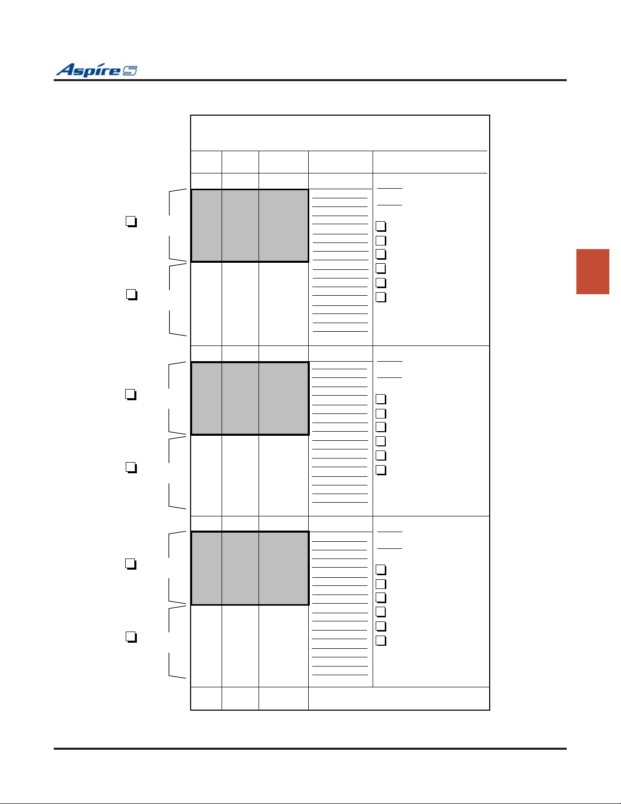
Section 3: Installing Extensions and Trunks
25-PAIR CABLE ____________________________
RJ-61
Connector 1
RJ-61
Connector 2
RJ-61
Connector 3
RJ-61
Connector 4
CONN
PIN
5
4
3
6
2
7
1
8
5
4
3
6
2
7
1
8
5
4
3
6
2
7
1
8
5
4
3
6
2
7
1
8
BLOCK
TERM
1
2
3
4
5
6
7
8
9
10
11
12
13
14
15
16
17
18
19
20
21
22
23
24
25
26
27
28
29
30
31
32
COLOR
CODE
WHT-BLU
BLU-WHT
WHT-ORN
ORN-WHT
WHT GRN
GRN-WHT
WHT-BRN
BRN-WHT
WHT-SLT
SLT-WHT
RED-BLU
BLU-RED
RED-ORN
ORN-RED
RED-GRN
GRN-RED
RED-BRN
BRN-RED
RED-SLT
SLT-RED
BLK-BLU
BLU-BLK
BLK-ORN
ORN-BLK
BLK-GRN
GRN-BLK
BLK-BRN
BRN-BLK
BLK-SLT
SLT-BLK
YEL-BLU
BLU-YEL
FUNCTION
PCB ID
Order Of Install
Slot #
8 ESIU
4 SLIU
4SLIDB DAUGHTER BRD
4VOIPU
4VOIPDB DAUGHTER BRD
2BRIU
Order Of Install
Slot #
8 ESIU
4 SLIU
4SLIDB DAUGHTER BRD
4VOIPU
4VOIPDB DAUGHTER BRD
2BRIU
3
Order Of Install
Slot #
8 ESIU
4 SLIU
4SLIDB DAUGHTER BRD
4VOIPU
4VOIPDB DAUGHTER BRD
2BRIU
RJ-61
Connector 5
RJ-61
Connector 6
0893130-100
50
25
5
4
3
6
2
7
1
8
5
4
3
6
2
7
1
8
33
34
35
36
37
38
39
40
41
42
43
44
45
46
47
48
49
50
YEL-ORN
ORN-YEL
YEL-GRN
GRN-YEL
YEL-BRN
BRN-YEL
YEL-SLT
SLT-YEL
VIO-BLU
BLU-VIO
VIO-ORN
ORN-VIO
VIO-GRN
GRN-VIO
VIO-BRN
BRN-VIO
VIO-SLT
SLT-VIO
NOT USED
Figure 3-4: EXTENSION CUTDOWN SHEET
Aspire S Hardware Manual Section 3: Installing Extensions and Trunks ◆ 3-7
Page 90

Section 3: Installing Extensions and Trunks
INSTALLING CO/PBX LINES
Loop Start Line Cabling
Loop start lines must be bridged from the telco RJ21X to a line cross-connect block (A). Each loop start CO/
PBX line requires one-pair cross-connect cable from the RJ21X to the line (A) block.
The A block connects to the trunk PCB with a 24 pair cable. The line (A) block(s) should be arranged in
groups of 4 (8 pins) to correspond to the COIU PCB slots.
The CN2 and CN4 connectors each provide connection to 4 analog trunk ports, whic
(tip to tip, ring to ring). The power failure circuits, however, are not polarity sensitive.
Installing Loop Start Lines (Figure 3-5)
To install a loop start line:
1. Punch down one pair cross-connect to the tip and ring leads for each line on the telco RJ21X CPE
(customer) side of the block.
The CN2 and CN4 connectors are polarity sensitiv
2. Punch down the other end of the cross-connect to the line (A) block (in groups of 4 lines of the
same line type).
3. Punch down a 25-pair cable to the opposite side of the line (A) block.
4. Plug in the corresponding RJ-61 connector to the COIU PCB connector (Figure 3-5).
5. Install bridging clips on the A block.
Note: Repeat steps 1-5 for each loop start line. Label cross-connect blocks A2, A3, etc.
h are polarity sensitive
e (tip to tip, ring to ring).
3-8 ◆ Section 3: Installing Extensions and Trunks Aspire S Hardware Manual
Page 91
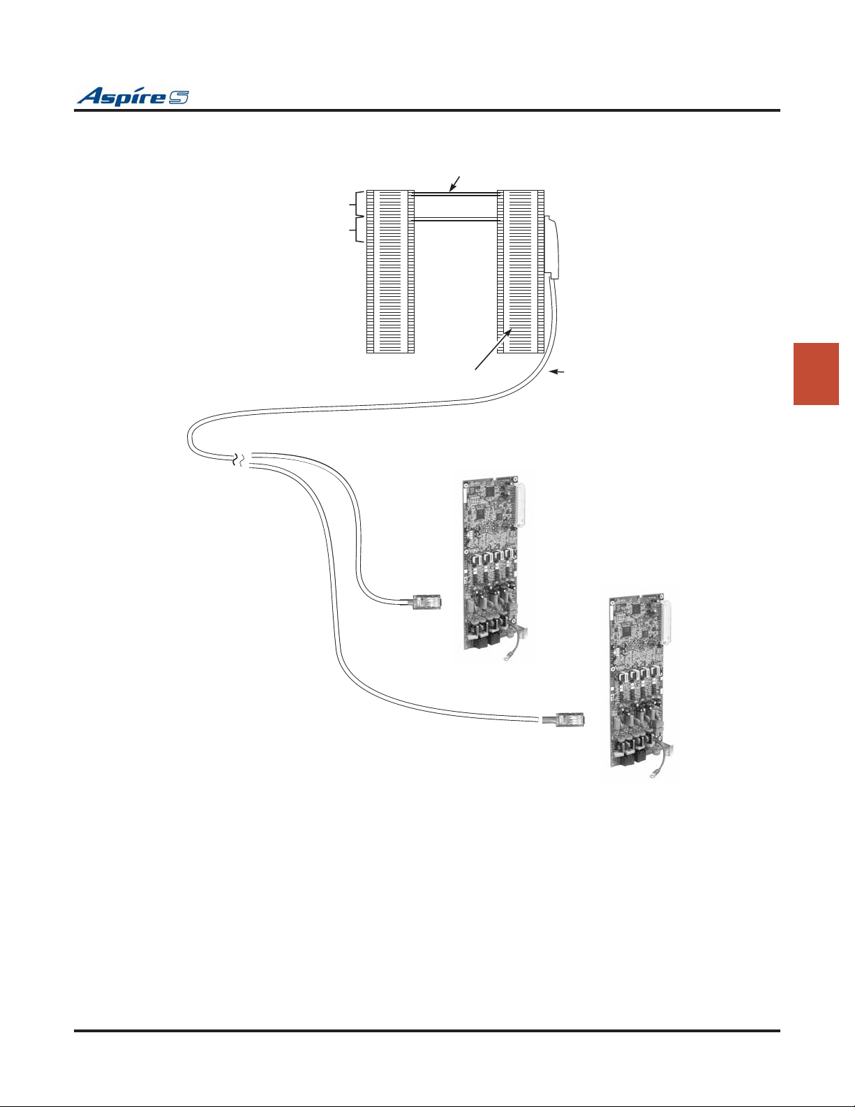
Section 3: Installing Extensions and Trunks
4 Loop
Start
Lines
4 Loop
Start
Lines
Telco
RJ21X
One-Pair
Xconnect
Loop Start
Lines 1-4
Loop Start
Lines 5-8
Bridging Clips
Line
"A" Block
25-Pair
Cable
3
4COUI
0893130-101
4COUI
Figure 3-5: INSTALLING LOOP START LINES
Aspire S Hardware Manual Section 3: Installing Extensions and Trunks ◆ 3-9
Page 92
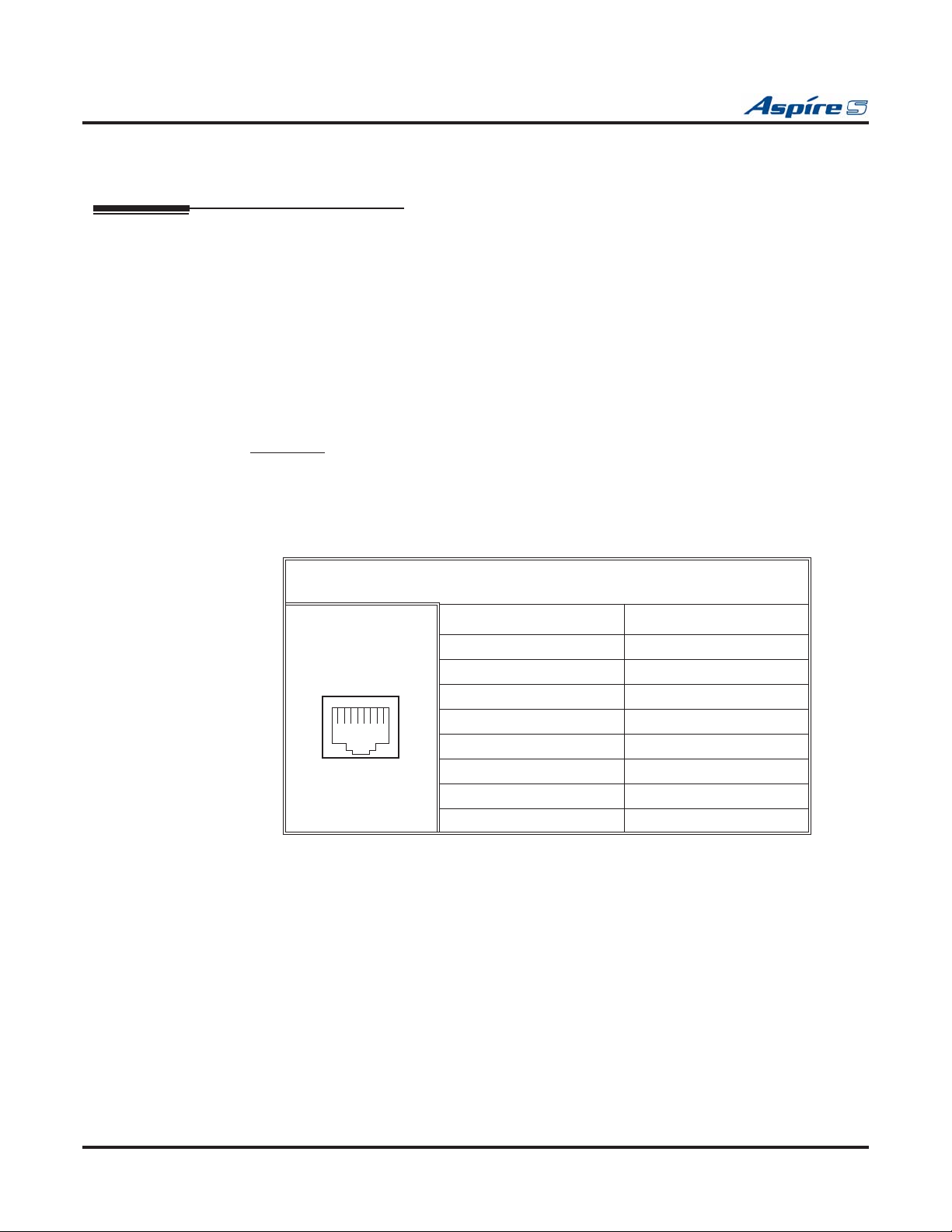
Section 3: Installing Extensions and Trunks
INSTALLING BRI TRUNKS
BRI Trunks (Figure 3-6)
BRI trunks must be bridged from the telco RJ21X to a line cross-connect (A) block. Each BRI Trunk
requires one-pair cross-connect from the RJ21X to the line (A) block.
The A block connects to the BRI PCB with a 25-pair cable and an RJ-61 jack. The line (A) block should be
arranged in groups of 2 BRI trunks (4 pins) to correspond with the cabinet slot equipped with a 2BRI PCB.
Installing BRI Trunks
1. For each T-Bus or S-Bus line, run cross-connect wires between the pins on the cross-connect block
and the station block.
2. Install bridging clips as required.
3. From the cross-connect block, connect 2 pairs of wires.
or T-Bus: The opposite end is an 8-pin modular connector which is plugged into the NT1 Termi-
F
nation. Connect a line cord from the NT1 Network Line Termination to the telco BRI line. Connect
the power cord to the NT1 Network Termination unit.
4. Plug in the corresponding RJ-61 connector to the BRI PCB connector.
Note: Repeat steps 1-4 for each BRI trunk. Label cross-connect blocks A2, A3, etc.
12345678
RJ45 Cable Connector - CN2
T-Bus Connection
Pin No. Connection
1-
2-
3TA
4RA
5RB
6TB
7-
8-
3-10 ◆ Section 3: Installing Extensions and Trunks Aspire S Hardware Manual
Page 93
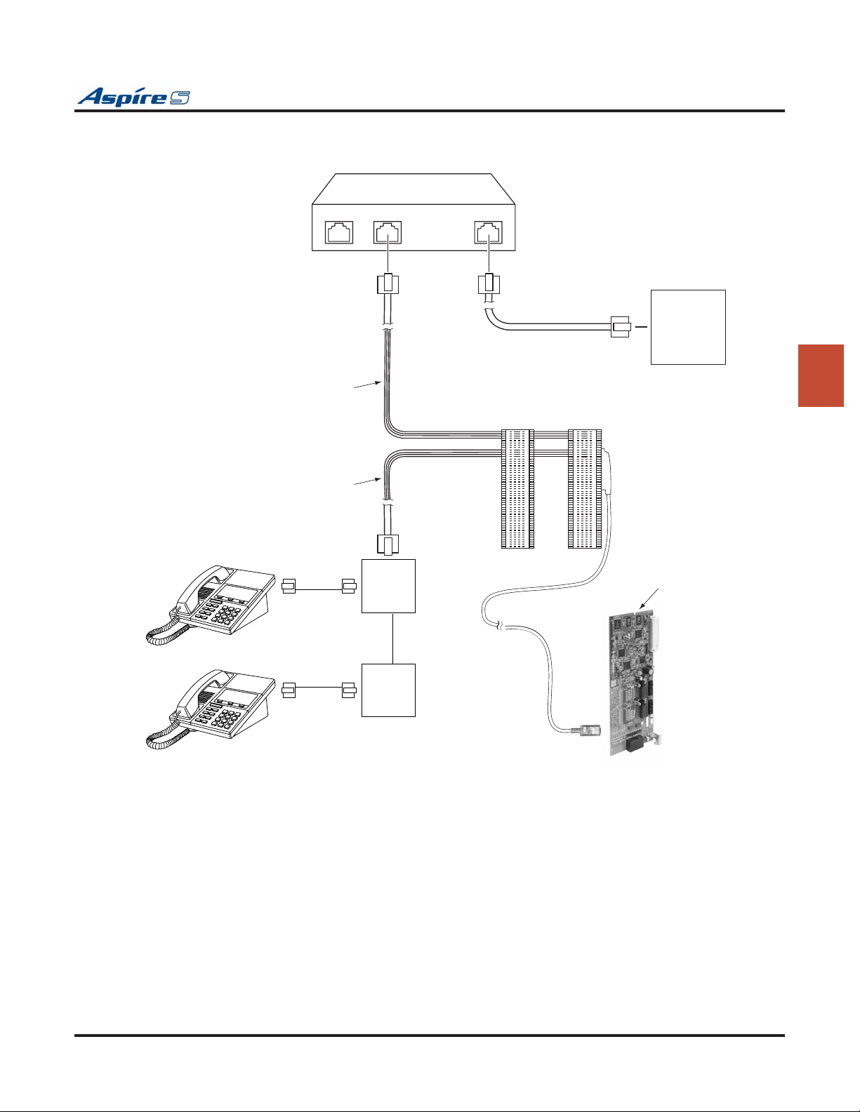
Section 3: Installing Extensions and Trunks
NT1 Termination
0893130-102
Termination Termination
Line
To Telco BRI Line
Telco
Mod Jack
T-Bus connection
S-Bus connection
Not Currently Available
(ISDN Terminal)
(ISDN Terminal)
RJ61
Jack
RJ61
Jack
Cross-
Connect
Block
Station
Block
3
BRI PCB
Figure 3-6: BRI Interface T-Bus Point-to-Point
Aspire S Hardware Manual Section 3: Installing Extensions and Trunks ◆ 3-11
Page 94
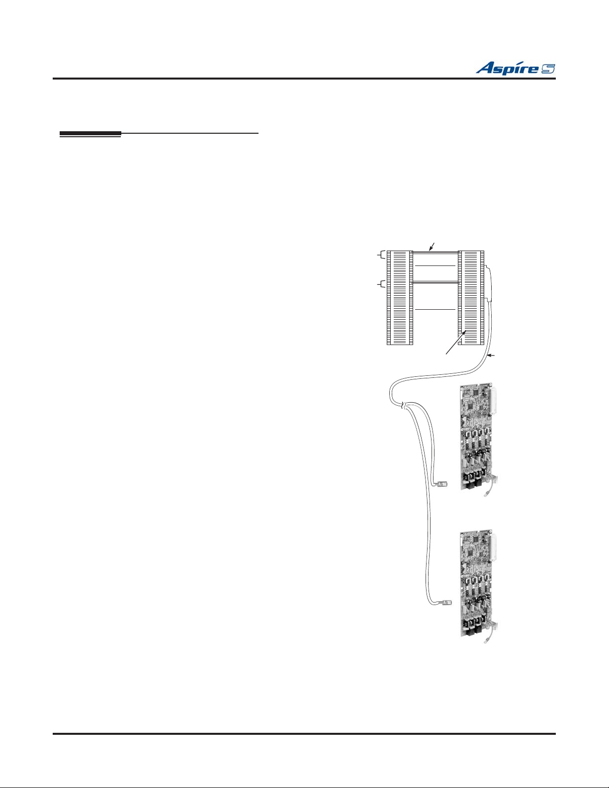
Section 3: Installing Extensions and Trunks
INSTALLING DID TRUNKS
DID Trunks (Figure 3-7)
Direct Inward Dialing trunks must be bridged from the telco RJ21X to a line cross-connect (A) block. Each
DID Trunk requires one-pair cross-connect from the RJ21X to the line (A) block.
The A block connects to the DID PCB and an RJ-61 jack. The line (A) block should be arranged in groups of
2 DID trunks (4 pins) to correspond with the cabinet slot equipped with a DIOPU PCB.
Installing DID Trunks
1. Punch down one pair cross-connect to
the tip and ring leads for each DID
trunk on the CPE (customer) side of
the RJ21X.
2. Punch down the other end of the crossconnect to the line (A) block tip and
ring leads.
3. Punch down a 25-pair cable to the
opposite side of the line (A) block.
4. Plug in the corresponding RJ-61 connector to the DID PCB connector.
5. Install bridging clips on the A block.
Note: Repeat steps 1-5 for each DID
trunk. Label cross-connect blocks
A2, A3, etc.
2 DID
Trunks
2 DID
Trunks
Telco
RJ21X
One-Pair
Xconnect
DID Trunks
1-2
Not used
DID Trunks
3-4
Bridging Clips
Line
"A" Block
DIOPU PCB
25-Pair
Cable
0893130-103
DIOPU PCB
Figure 3-7: INSTALLING DID TRUNKSI
3-12 ◆ Section 3: Installing Extensions and Trunks Aspire S Hardware Manual
Page 95
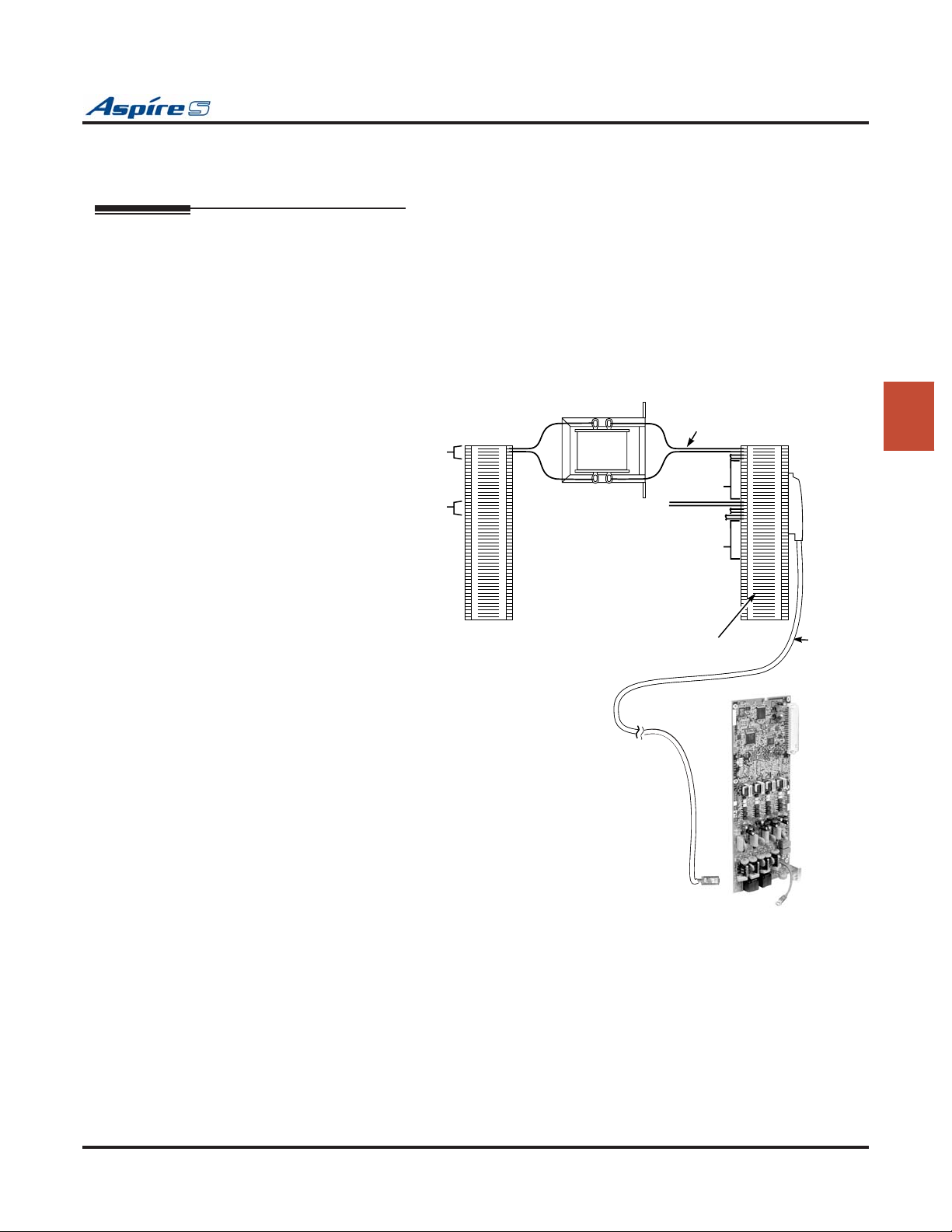
Section 3: Installing Extensions and Trunks
INSTALLING A DID CHOKE
DID Choke (Figure 3-8)
If your central office has a high level of AC noise or if your site is experiencing excessive hum on the DID
lines, a customer-provided isolation transformer can be installed between the Aspire S and telco blocks to
help to suppress the hum.
DID trunks must be bridged from the telco RJ21X to a line cross-connect (A) block. The choke is installed
between these two blocks.
DID Choke Installation:
1. Remove the bridging
clips on the (A)
block and telco
block for the DID
lines.
2. From the telco
block, solder the Tip
lead to the “3” connector on the choke.
3. From the telco
block, take the Ring
lead and solder it to
the “1” connector on
the choke.
4. From the (A) block,
take the Tip 1 lead
and solder it to the
“4” connector on the
choke.
5. Solder the Ring 1
lead from the (A)
block to the “2” connector on the choke.
6. Reinstall the bridging clips as required.
2 DID
Trunks
2 DID
Trunks
Telco
RJ21X
TT1
3
1
RR1
One-Pair
4
2
Xconnect
DID Trunks
1-2
Not used
DID Trunks
3-4
Not used
Bridging Clips
Line
"A" Block
25-Pair
Cable
0893130-104
3
DIOPU PCB
Figure 3-8: DID CHOKE INSTALLATION
Aspire S Hardware Manual Section 3: Installing Extensions and Trunks ◆ 3-13
Page 96

Section 3: Installing Extensions and Trunks
LINE/TRUNK CUTDOWN SHEET
CO/PBX Line Cutdown Sheet Configuration (Figure 3-9)
Due to the flexibility of the system’s universal PCB slot configuration, standard cutdown sheets for CO/PBX
line cabling do not apply.
Note: The order in which the trunk PCBs are installed determines the assigned line circuit
number.
For example, if three PCBs are installed in the cabinet in the following order (powering down between the
PCB installation), the following numbering plan would be in effect:
Order of Install PCB Slot # PCB Line Circuits
1 4 2DIOPU-S 1-2
2 5 4COIU-S 3-6
3 6 2DIOPU-S 7-8
To determine trunk assignments for the system cutdown, the installer must identify the following in order:
● Order of installation
● Slot used
● PCB type (4COIU-S, 2BRIU-S, 2DIOPU-S, 4VOIPU-S, 4VOIPU-S with 4VOIPDB-S)
● Amphenol connector
To determine where any group of lines are installed, note the order of install and slot.
On the following page is the line cutdown sheet (Figure 3-9). Make as many copies as you need. Be sure to
keep careful records of your installation.
3-14 ◆ Section 3: Installing Extensions and Trunks Aspire S Hardware Manual
Page 97
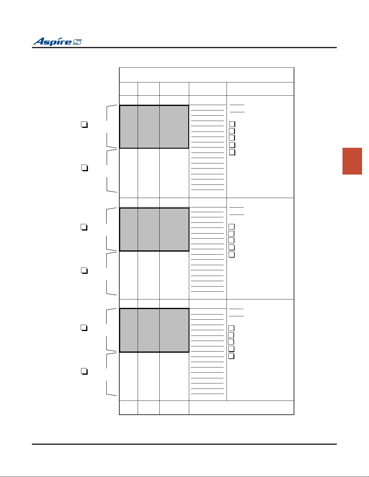
Section 3: Installing Extensions and Trunks
25-Pair Connector ___________________________
RJ-61
Connector 1
RJ-61
Connector 2
RJ-61
Connector 3
RJ-61
Connector 4
CONN
PIN
4
5
3
6
2
7
1
8
4
5
3
6
2
7
1
8
4
5
3
6
2
7
1
8
4
5
3
6
2
7
1
8
BLOCK
TERM
1
2
3
4
5
6
7
8
9
10
11
12
13
14
15
16
17
18
19
20
21
22
23
24
25
26
27
28
29
30
31
32
COLOR
CODE
WHT-BLU
BLU-WHT
WHT-ORN
ORN-WHT
WHT GRN
GRN-WHT
WHT-BRN
BRN-WHT
WHT-SLT
SLT-WHT
RED-BLU
BLU-RED
RED-ORN
ORN-RED
RED-GRN
GRN-RED
RED-BRN
BRN-RED
RED-SLT
SLT-RED
BLK-BLU
BLU-BLK
BLK-ORN
ORN-BLK
BLK-GRN
GRN-BLK
BLK-BRN
BRN-BLK
BLK-SLT
SLT-BLK
YEL-BLU
BLU-YEL
FUNCTION
PCB
ID
Order Of Install
Slot #
4COIU
2BRIU
2DIOPU
4VOIPU
4VOIPU with 4VOIPDB
3
Order Of Install
Slot #
4COIU
2BRIU
2DIOPU
4VOIPU
4VOIPU with 4VOIPDB
Order Of Install
Slot #
4COIU
2BRIU
2DIOPU
4VOIPU
4VOIPU with 4VOIPDB
RJ-61
Connector 5
RJ-61
Connector 6
0893130-105
50
25
4
5
3
6
2
7
1
8
4
5
3
6
2
7
1
8
33
34
35
36
37
38
39
40
41
42
43
44
45
46
47
48
49
50
YEL-ORN
ORN-YEL
YEL-GRN
GRN-YEL
YEL-BRN
BRN-YEL
YEL-SLT
SLT-YEL
VIO-BLU
BLU-VIO
VIO-ORN
ORN-VIO
VIO-GRN
GRN-VIO
VIO-BRN
BRN-VIO
VIO-SLT
SLT-VIO
NOT USED
Figure 3-9: LINE CUTDOWN SHEET
Aspire S Hardware Manual Section 3: Installing Extensions and Trunks ◆ 3-15
Page 98
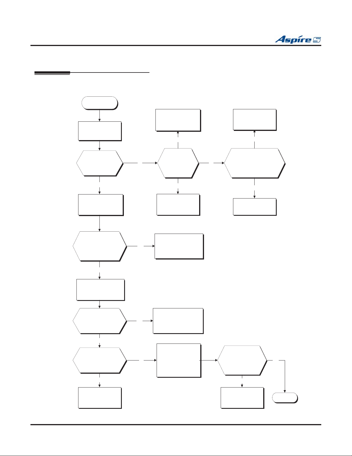
Section 3: Installing Extensions and Trunks
TROUBLESHOOTING
Basic Troubleshooting
Troubleshooting Digital Extensions
Start
Verify the ESIU PCB
is functioning.
Is the Live
Status LED on
the ESIU PCB
flashing green?
Yes
Verify whether a digital
keyset works.
Connect a test
telephone to a port
using another
modular jack. Does
the phone work?
No
Verify the wiring
between the cabinet and
the keyset.
No
Yes
Move the Run/Block
switch on the PCB to
the RUN position.
Yes
Is the Live
Status LED
solid green?
No
Main equipment
(cabinet/CPU) may
need repair.
Redo the wires between
the main equipment and
the modular jack.
* If it still does not work,
replace the cable(s) and/
or connectors.
No
Main equipment
(cabinet/CPU) may
need repair.
No
Remove the PCB and
insert another ESIU
PCB into the same slot.
Does it work?
Yes
The ESIU PCB may
need repair.
Connect the phone
directly to the
connector on the
ESIU. Does it work?
No
Connect another
telephone to the
same port on the
ESIU. Does it work?
Yes
The telephone may
need repair.
Yes
Redo the wires between
the main equipment and
the telephone.
Check system
programming for the
No
extension. Refer to the
Aspire Software
Manual if necessary.
* If it still does not work,
replace the cable(s) and/
or connectors.
Connect the
phone directly to
the connector on
the ESIU. Does it
work?
No
The ESIU PCB may
need repair.
Yes
Stop
3-16 ◆ Section 3: Installing Extensions and Trunks Aspire S Hardware Manual
Page 99

Section 3: Installing Extensions and Trunks
TESTING TELEPHONE OPERATION
The following procedure will help you determine if a problem being experienced is due to the telephone or
the system. Testing the operation of a keyset allows you to check the lamping of each key, the display, and
tones. Follow the procedure below to determine if the phone is operating correctly.
ey Matrix and LED Test
K
1. Unplug the phone.
2. While holding down dial pad digits 1, 2 and 3, plug the phone back in.
3. Hold down the 1, 2 and 3 digits for approximately 10 seconds then release them.
If the phone doesn’t show “TEST PUSH=” on the display, then repeat Steps 1-3 and hold the
keys down a few seconds longer.
4. Press any key and its Logical Name should be displayed.
The following chart indicates the Logical Name for each key.
Logical Name Table
Keys
KEYPAD 0 - 9 D 0 - D 9 CALL2 F 8
KEYPAD * D * MIC F 9
KEYPAD # D # MSG F 10
Line Keys 1 - 24
DSS Keys 1 - 10 O 1 - O 10 CLEAR F 12
LND F 1 CHECK F 13
CONF F 2 SOFT KEY 1-4 S 1 - S 4
HOLD F 3
FLASH F 4
DND F 5 VOL. UP
CALL1 F 6 VOL. DOWN
SPK F 7
1
Logical
Name Keys
L 1 - L 24 DIAL F 11
MENU1
MENU2
2
2
Logical
Name
011
012
3
1
Keys 1, 2 and 3 will also check tones.
2
34-Button Super Display telephone only.
Quitting
Aspire S Hardware Manual Section 3: Installing Extensions and Trunks ◆ 3-17
Test Mode
1. Lift the handset and then replace it.
2. The phone returns to an idle condition.
Page 100
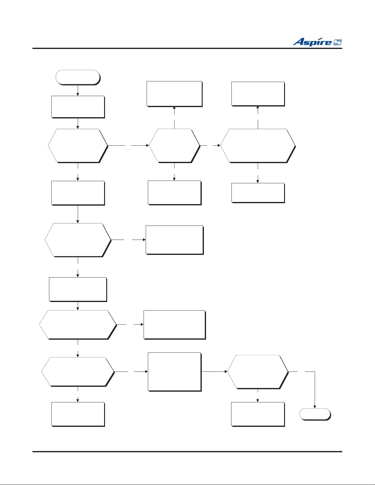
Section 3: Installing Extensions and Trunks
Troubleshooting Analog Extensions
Start
Verify the SLIU/SLIDB
PCB is functioning.
Move the Run/Block
switch on the PCB to
the RUN position.
Yes
Main equipment
(cabinet/CPU) may
need repair.
No
Is the Live Status
LED on the SLIU/
SLIDB PCB
flashing green?
Yes
Verify whether a
analog phone works.
Connect a test
telephone to a port
using another
modular jack. Does
the phone work?
No
Verify the wiring
between the cabinet and
the analog telephone.
No
Yes
Is the Live
Status LED
solid green?
No
Main equipment
(cabinet/CPU) may
need repair.
Redo the wires between
the main equipment and
the modular jack.
* If it still does not work,
replace the cable(s) and/
or connectors.
No
Remove the PCB and
insert another SLIU/
SLIDB PCB into the
same slot. Does it work?
Yes
The SLIU/SLIDB PCB
may need repair.
Connect the phone
directly to the connector
on the SLIU/SLIDB. Does
it work?
No
Connect another
telephone to the same
port on the SLIU/
SLIDB. Does it work?
Yes
The telephone may
need repair.
Yes
No
Redo the wires between
the main equipment and
the telephone.
Check system
programming for the
extension. Refer to the
Aspire Software
Manual if necessary.
* If it still does not work,
replace the cable(s) and/
or connectors.
Connect the
phone directly to
the connector on
the SLIU/SLIDB.
Does it work?
No
The SLIU/SLIDB PCB
may need repair.
Yes
Stop
3-18 ◆ Section 3: Installing Extensions and Trunks Aspire S Hardware Manual
 Loading...