

NEC AccuSync LCD51VM, AccuSync LCD51VM(A), AccuSync LCD51VM-BK(A), AccuSync LCD51VM-BK(B) Service Manual

COLOR MONITOR
AccuSync
TM
LCD51VM
MODEL ID LCD51VM(A)/-BK(A)/-BK(B)
200309
08R510AY
08R520AY
08R520BY
SERVICE MANUAL
PART NO. 599910663
1st Edition
NEC-MITSUBISHI ELECTRIC VISUAL SYSTEMS CORPORATION
JULY 2003
WARNING
The SERVICE PERSONNEL should have the appropriate technical training, knowledge and experience
necessary to:
• Be familiar with specialized test equipment, and
• Be careful to follow all safety procedures to minimize danger to themselves and their coworkers.
To avoid electrical shocks, this equipment should be used with an app ropriate power cord.
This equipment utilized a micro-gap power switch. Turn off the set by first pushing power switch. Next,
remove the power cord from the AC outlet.
To prevent fire or shock hazards, do not expose this unit to rain or moisture.
This symbol warns the personnel that un-insulated voltage within the unit may have sufficient
magnitude to cause electric shock.
This symbol alerts the personnel that important literature concerning the operation and
maintenance of this unit has been included.
Therefore, it should be read carefully in order to avoid any problems.
PRODUCT SAFETY CAUTION
1. When parts replacement is required for servicing, always use the manufacturer's specified replacement.
2. When replacing the component, always be certain that all the components are put back in the place.
3. As for a connector, pick and extract housing with fingers properly since a disconnection and improper
contacts may occur, when wires of the connector are led.
4. Use a proper screwdriver. If you use screwdriver that does not fit, you may damage the screws.

CONTENTS
Page No.
USER'S MANUAL -------------------------------------------------------------------- 1-1
SERIAL NUMBER INFORMATION ---------------------------------------------- 2-1
DISASSEMBLY ----------------------------------------------------------------------- 3-1
ADJUSTMENT PROCEDURES --------------------------------------------------- 4-1
INSPECTION ---------------------------------------------------------------------------- 5-1
TROUBLE SHOOTING -------------------------------------------------------------- 6-1
CIRCUIT DESCRIPTION ------------------------------------------------------------ 7-1
REPLACEMENT PARTS LIST ---------------------------------------------------- 8-1
BLOCK DIAGRAM ------------------------------------------------------------------- 9-1
SCHEMATIC DIAGRAMS ---------------------------------------------------------- 10-1
PACKING SPECIFICATION -------------------------------------------------------- 11-1
1-1
User's Manual
1. A Version
AccuSync
TM
LCD51VM/LCD71VM

1-2
W
arning .................................................................................................................... 1
Content
s ................................................................................................................. 2
Quic
k
Start .............................................................................................................
3
C
ontrols ................................................................................................................... 7
Recommen
ded
Use.............................................................................................. 10
Sp
ecif
ications .......................................................................................................12
F
eatures ............................................................................................................... 14
Tr
oubleshooting ................................................................................................... 15
R
eferences .............................................................................................................16
Limited Warranty................................................................................................. 17
T
C
O ‘99 .................................................................................................................. 18
Av
ertissement ......................................................................................................21
Cont
enu................................................................................................................. 22
Mise en marc
h
e rapide ...................................................................................... 23
Co
mmandes .......................................................................................................... 27
Usage recommand
é
............................................................................................ 3
0
Spécifica
t
ions
......................................................................................................
32
Fonctions ............................................................................................................. 34
D
é
pannage ............................................................................................................ 35
R
éfé
rences ........................................................................................................... 36
Ga
r
antie limitée .................................................................................................. 3
7
TCO ‘99 .................................................................................................................. 38
Index
1-3
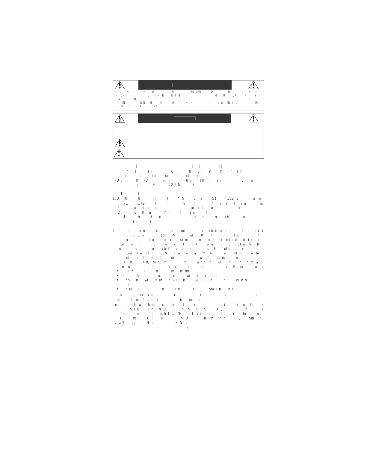
CAUTION: TO REDUCE THE RISK OF ELECTRIC SHOCK, MAKE SURE POWER CORD IS UNPLUGGED FROM
WALL SOCKET. TO FULLY DISE
N
GAGE THE POWER TO THE UNIT, PLEASE DISCONNECT THE POWER
CORD FROM THE AC OUTLET. DO NOT REMOVE COVER
(
OR BACK). NO USER SERVICEABLE PARTS
I
N
SIDE. REFER SERVICING TO QUALIFIED SERVICE PERSONNEL.
Thi
s
symbol warns user that uninsulated voltage within the unit may have sufficient magnitude to cause
electric shock. Therefore, it is dangerous to make any kind of contact with any part inside this unit.
This symbol alerts the user that important literature concerning the operation and maintenance of thi
s
unit has been included. Therefore, it should be read carefully in order to avoid any problems
.
W
ARNIN
G
CAUTI
ON
ttctctt
t
T
ttt
tft
tft
t
twtftyt
t
A
A
t
ttt
f
w
t
t
AyV)A
y
V
)
ttt
t
f
w
t
tvt
)
t
w
v
t
t
)
t
v
f
t
tyt
f
w
t
tvt
T
tttft
y
w
tttft
v
tttftTt
t
v
tttftfttt
T
ttt
f
y
y
f
t
t
w
ttt
t
y
ftf
t
t
w
v
ttttt
f
w
t
tttft
tftft
tvtwtyttt
f
f
f
t
t
tyttt
t
fyftf
w
tttvt
tttwt
tvttttttt
f
f
f
tftttwt
v
t
t
y
T
Vtf
f
y
tttttvt
f
t
t
Tyftf
w
tyt
t
f
w
t
t
f
y
y
vTVtf
Ttv
ftv
t
t
f
ffW
t
t
TVTAATXTTTATA
T
TTAWTAXTTATTT
T
AYT
ATATATAVTAT
V
TAV
f
t
t
yvy
t
t
y
f
v
tttyttt
t
1-4
onten
ts
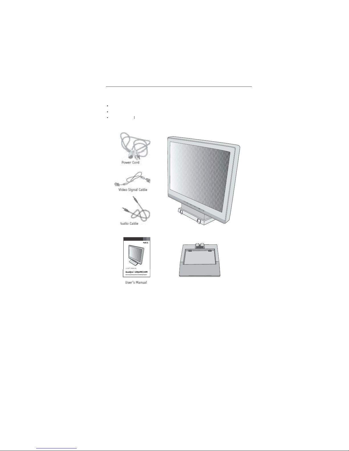
emember to save your original box and packing material to transport or ship the monitor.
Your new NEC AccuSync LCD monitor box* should contain t
he
ollowing:
AccuSync LCD monitor with tilt base • Audio Ca
ble
er Cor
d
• Video Signal Ca
ble
User’s Manu
a
• Base stan
d
A
A
ccuSync LCD monitor (base stand not connected
)
ase
an
d

1-5
Quick Star
t
To
attach the Base to the LCD Stan
d:
1. Insert the front of the LCD Stand into the holes in the front of the Base
.
2. Next, position the locking tabs on the back side of the LCD Stand with the holes on the
Base. Lower t
h
e Stand until locking tabs are secure
.
To
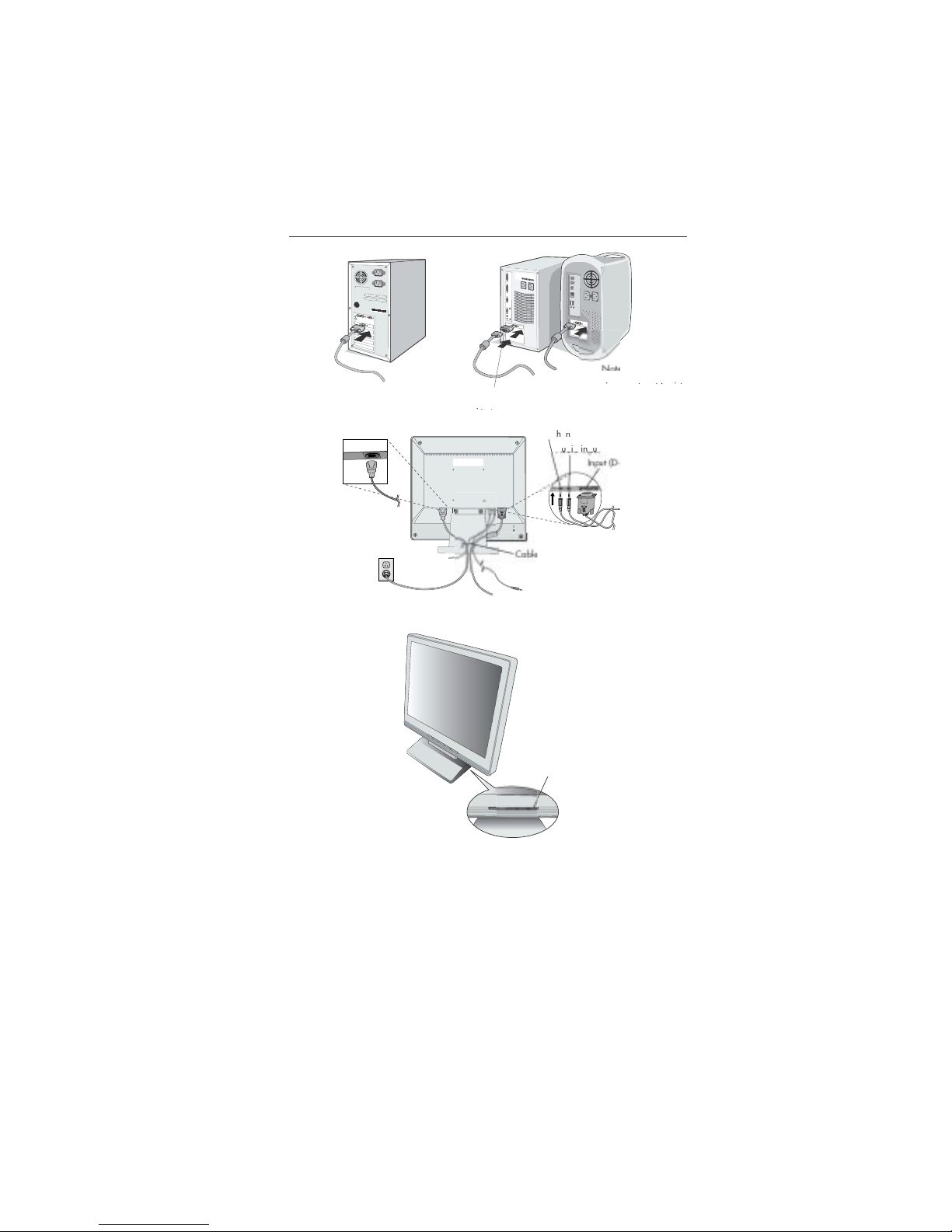
attach the AccuSync LCD monitor to your system, follow these instructions
:
1. Turn off the power to your computer
.
connector of the display card in your system
gp
Figure A.1). Tighten all screws
.
For the MAC: Connect the AccuSync Macintosh cable adapter to the computer, the
n
attach the 15-pin mini D-SUB signal cable to the AccuSync Macintosh cable adapte
r
Figure A.2). Tighten all screws
.
NOTE: To obtain the AccuSync Macintosh cable adapter, call NEC-Mitsubishi Electronic
s
Display of America, Inc. at (800) 632-4662
.
3. Connect the 15-pin mini D-SUB of the video signal cable to the appropriate connecto
r
on the back of the monitor
Figure B.1). Connect the audio cable to AUDIO-INPUT o
n
the back of the monitor and the other end to the “Audio out” terminal of the computer
.
monitor
“
ypp
be disabled. Headphones can be purchased from your local electronics store
.
4. Connect one end of the power cord to the LCD and the other end to the power outlet
.
Place the video signal cable and power cord between the cable holder
Figure B.1
)
NOTE: Adjust the position of cables between the holder to avoid damage
.
NOTE: If you use this monitor at AC125-240V, please refer to Recommended Us
e
section of this manual for proper selection of power cord
.
5. Turn on the monitor with the front power button and the computer.
Figure C.1
)
6. No-touch Auto Adjust automatically adjusts the monitor to optimal settings upon initia
l
setup for most timings. For further adjustments, use the following OS
M
®
controls:
• Auto Adjust Contras
t
• Auto Adjus
t
Refer to the Controls section of this User’s Manual for a full description of thes
e
OSM controls
.
TE:For download information on the Windows
®
95/98/Me/2000/XP INF file for your AccuSync
monitor, refer to the References section of this User’s Manual
.
TE:If you have any problems, please refer to theTroubleshooting section of this User’s Manual
.
1
Locking Ta
bs
nt Bas
e
Stan
d
as
e
1-6
4
Quick Start
–continue
d
systems do not require
a
MacintoshCable Adapter
yqq
Figure A.
1
Figure C.
1
Figure A.
2
Macintosh Ca
ble
Adapte
r
pp
igure B.
1
u
b)
holder
eadoe
Power butto
n
1-7
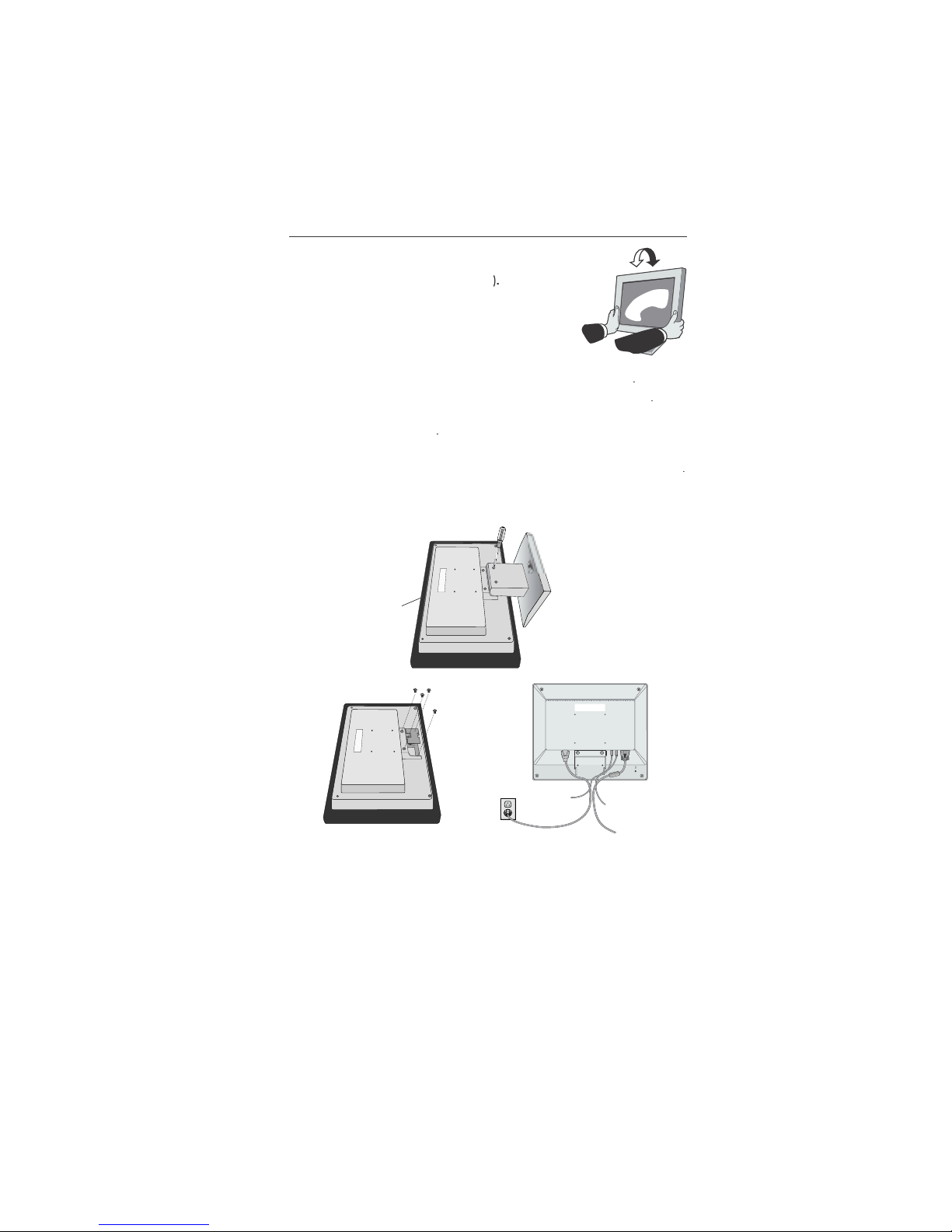
Ti
lt
Grasp both sides of the monitor screen with your hand
s
and adjust the tilt as desired (Figure TS.
1
Remove Monitor Stand for Mountin
g
To prepare the monitor for alternate mounting purposes
:
1.Disconnect all cables
.
2.Place monitor face down on a nonabrasive surface (Figure R.1
)
3.Remove the 2 screws on the stand and lift off the stand
Figure R.1
)
4.Remove the 4 screws connecting the monitor to the stand and remove t
he
metal plate
Figure R.2
)
The monitor is now ready for mounting in an alternate manner
.
Connect the AC cord and signal cable to the back of the monitor
Figure R.3
)
6. Reverse this process to reattach stan
d.
NOTE: Use only VESA-compatible alternative mounting metho
d.
TE:Handle with care when removing monitor stan
d.
Quick Start
–continue
d
Figure TS.
1
Figure R.
2
igure R.
1
non-abrasiv
e
surfac
e
Figure R.
3
1-8
Quick Start
–continue
d
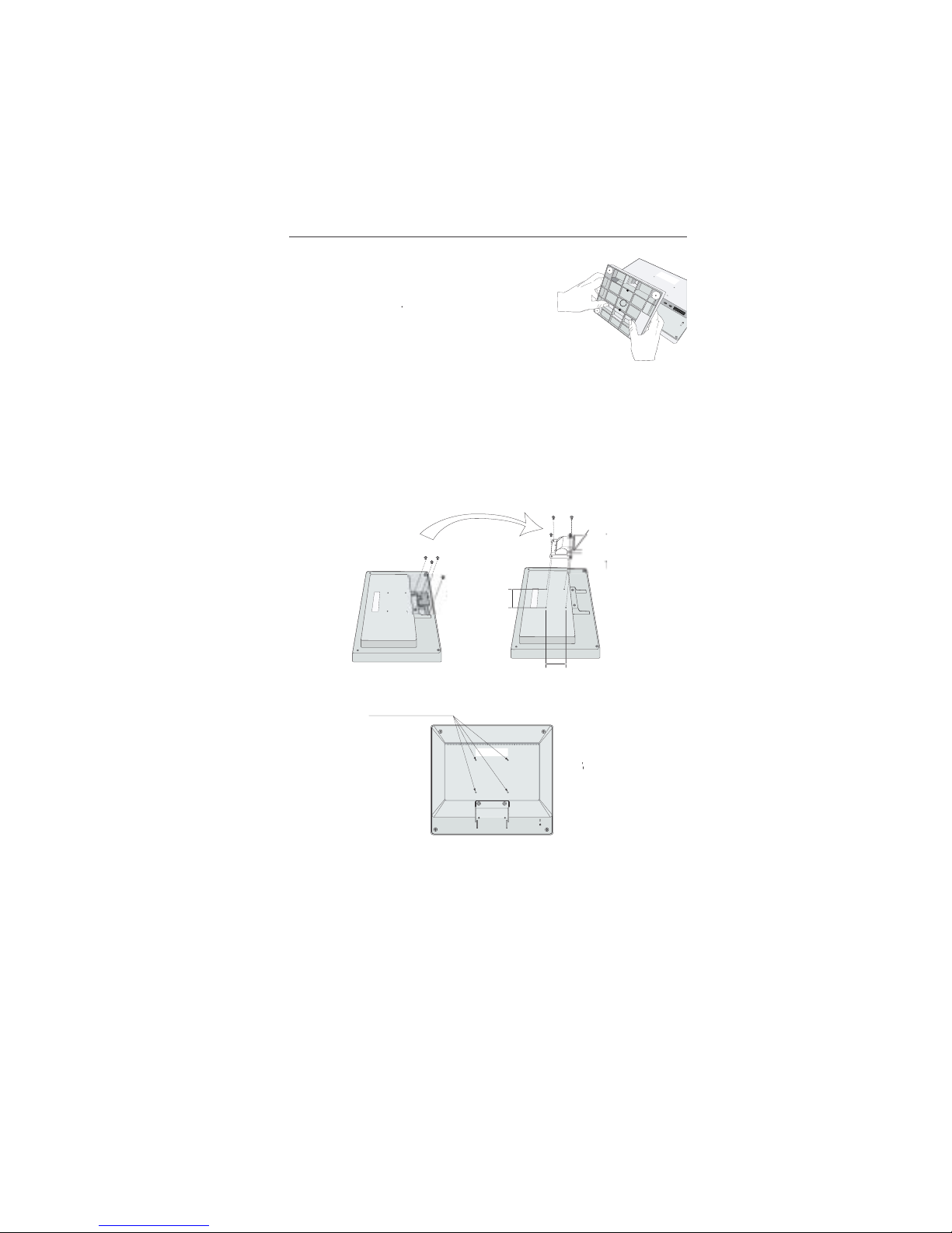
Removing the Bas
e
Note: Always remove the Base when shipping the LCD
.
Place monitor face down on a non-abrasiv
e
surface (Figure R.1
)
2. While using your thumbs, press the bottom ta
bs
upward to unloc
k.
3. Press the top tabs down to unlock and pull off the stand
.
Connecting a Flexible Ar
m
This LCD monitor is designed for use with a flexible arm. Please use the attache
d
screws (4pcs) as shown in the picture when installing
.
To meet the safety requirements, the monitor must be mounted to an arm whic
h
guaranties the necessary stability under consideration of the weight of the monitor
.
The LCD monitor should only be used with an approved arm (e.g. GS mark)
.
Replace screw
s
Specification
s
If using other screws, check depth of holes
.
4-SCREWS (M4
)
ighten all screws
.
Thickness of Bracket (Arm
)
.0~3.2 m
m
(MAX depth: 8.5 mm
)
75 mm (LCD51VM
)
100 mm (LCD71VM
)
5 mm (LCD51VM
)
100 mm (LCD71VM
)
W
eight of LCD assembly:
2.6 kg - LCD51VM (MAX
)
4.0 kg -LCD71VM (MAX
)
1-9
ontro
ls
S
M
®
(On-Screen Manager) control buttons on the front of the
monitor function as follows
:
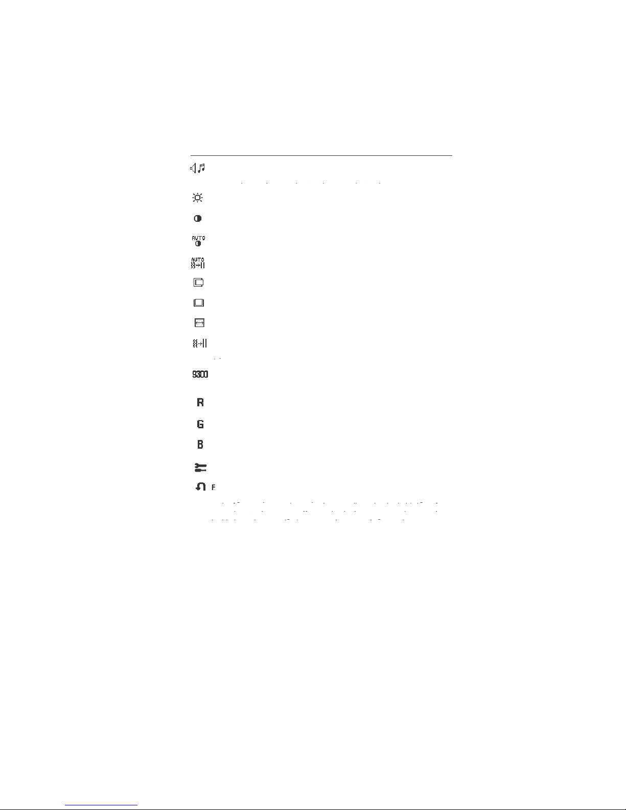
VOLUM
E
UT
E
%
OSM displaye
d
adjust window
g
utton
OSM Of
f
Shortcut to volum
e
adjust windo
w
OSM On
(Icon selectio
n
stage
)
M
oves t
o
Adjustment stag
e
Cursor moves le
ft
ursor moves
OSM On
(Adjustmen
t
stage
)
M
oves to Ico
n
selection stag
e
Adjust value
d
ecrease o
r
j
moves le
ft
Adjust value
ncrease o
r
j
moves rig
ht
Reset operatio
n
Mute o
ff/
on Volum
e
adjustment windo
w
SELE
CT
–
+
AU
TO
/ RESET
1. Basic key functio
n
.
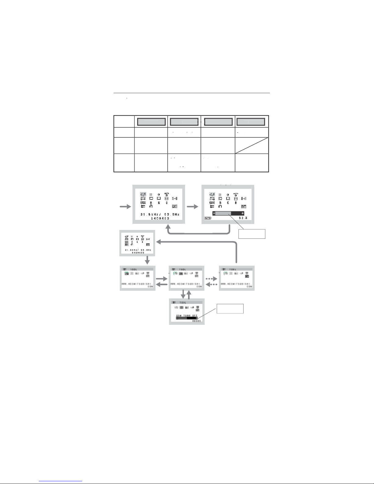
OSM S
tructur
e
Main Menu (Icon Select
)
Sub Menu (Icon Select
)
res
s
ELECT
”
e
y
res
s
ELECT
”
e
y
ress
“–“ or “ +”
–
“
Adjust by usin
g
–“ or “ +
”.
Main Menu (Adjust
)
(j)
Sub Menu (Adjust
)
y
Press “SELECT
”
e
y
res
s
–“ or “ +
”
“
Adjust by usin
g
–“ or “ +
”.
Press “SELECT” ke
y
ress “SELECT” ke
y
1-10
ontrols
–continue
d
A
UDI
O
Control the sound volume of speakers and headphone.
To mute the speaker sound, press the AUTO/RESET key.
pppp
BRIGHTNE
SS
Adjusts the overall image and background screen brightness
.
CONTRAST
Adjusts the image brightness in relation to the backgroun
d.
AUTO CONTRAST
Adjusts the image displayed for non-standard video inputs
.
AUTO A
DJU
ST
Automatically adjusts the Image Position, the H. Size and Fine setting
.
LEFT/RIGH
T
Controls Horizontal Image Position within the display area of the LCD
.
DOWN/U
P
Controls Vertical Image Position within the display area of the LCD
.
H. SIZ
E
Adjusts the horizontal size by increasing or decreasing this setting
.
FI
NE
p
COLOR CONTROL SYSTEMS
Four color presets (9300/7500/6500/USER) select the desired colo
r
setting
.
COLO
R RE
D
Increase or decreases Red. The change will appear on screen
.
COLOR G
REE
N
Increase or decreases Green. The change will appear on screen
.
COLO
R BLU
E
Increase or decreases Blue. The change will appear on screen
.
T
OOL
Selecting TOOL allows you to get into the sub menu
.
ACTORY PRESET
gy y g
gy y g
yg
yg
ighlighting the control to be reset and pressing the RESET button
.
gg
gg
1-11
ontrols
–continue
d
OSM
®
Warning:
OSM Warning menus disappear with SELECT button
.
SI
GNAL:
This function gives a warning when there is no signal present.
gg
gppgpp
After power is turned on or when there is a change of input signal or video
gg gpgg gp
is inactive, t
he
p
No Signa
l
window will appear.
RESOLUTION NOTIFIER
:
This function gives a warning of use with
pp
optimized resolution. After power is turned on or when there is a change
gg
gg
of input signal or the video signal doesn’t have proper resolution, the
pp g
pp g
Resolution Notifie
r
pg
pg
window will open. This function can be disabled i
n
gpp
gpp
the TOOL menu
.
O
UT OF R
ANGE:
This function gives a recommendation of the optimize
d
gpgp
of input signal or the video signal doesn’t have proper timing, the
pp
Out Of
g
ang
e
menu will appear
.
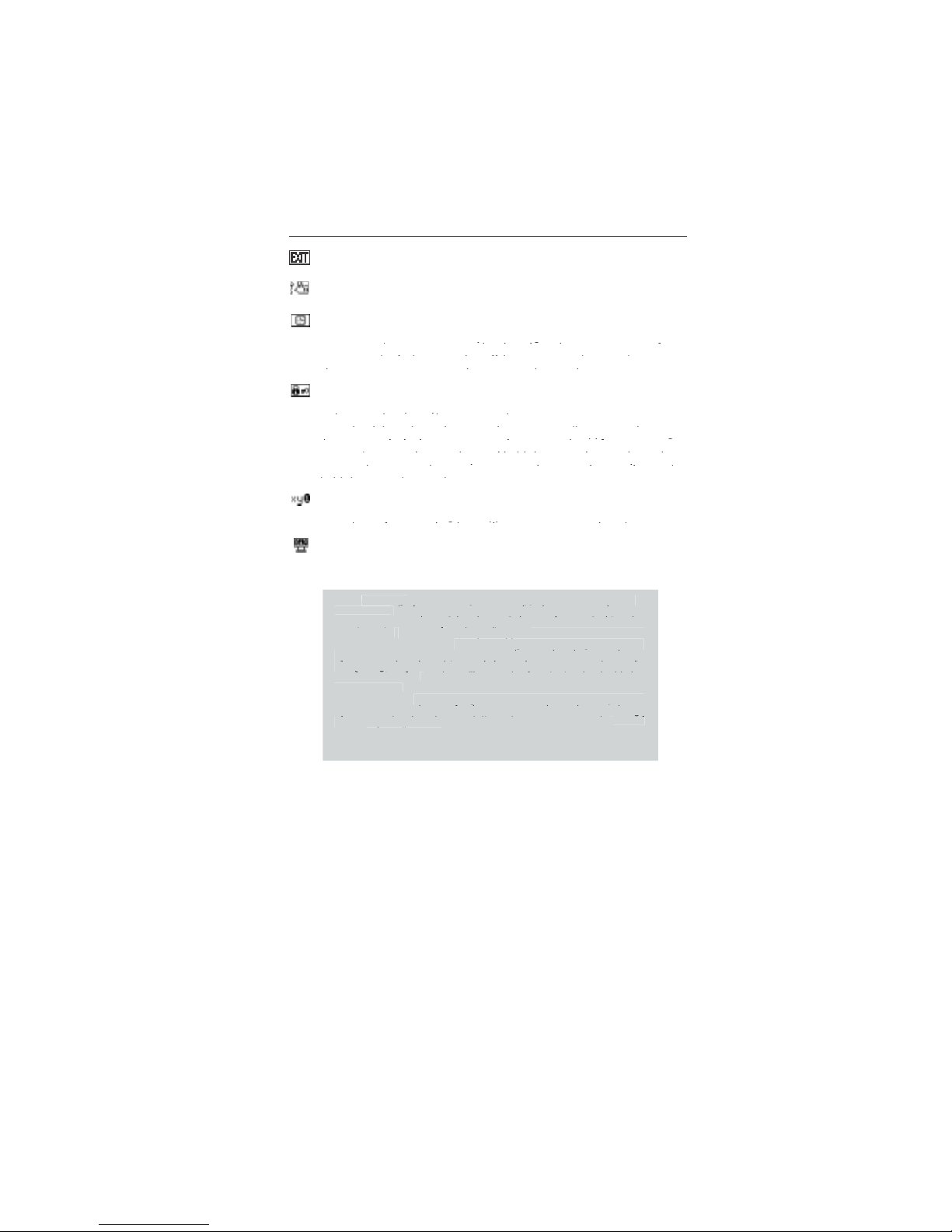
g
Selecting EXIT allows you exit OSM menu/sub menu
.
L
ANGUAGE
OSM control menus are available in seven languages
.
OSM
TURN OF
F
The OSM control menu will stay on as long as it is in use. In the OSM
Tu
OFF submenu, you can select how long the monitor waits after
yg
yg
yg
yg
choices are 10 - 120 seconds in 5 second intervals
.
OSM LOCK OUT
This control completely locks out access to all OSM control function
s
without Brightness and Contrast. When attempting to activate OSM
pypy
gpg
gpg
pp g
pp
“AUTO/ RESET“, then “+“ key and hold down simultaneously. To de
-
p
p
yy
yy
old down simultaneously
.
RESOLUTION NOTIFIE
R
If ON is selected, a message will appear on the screen after 3
0
gpp
gpp
MONITO
R INF
O
Indicates the model and serial numbers of your monitor.
1-12
1
0
commended Us
e
Safety Precautions and Maintenanc
e
FOR OPTIMUM PERFORMANCE, PLEASE NOTE TH
E
FOLLOWING WHEN SETTING UP AND USING
THE ACCUSY
N
C LCD COLOR MONITOR
:
DO NOT OPEN THE
MONITO
R. There are no user serviceable parts inside and opening o
r
removing covers may expose you to dangerous shock hazards or other risks. Refer all servicing t
o
qualified service personnel
.
Do not spill any liquids into the cabinet or use your monitor near water
.
Do not insert objects of any kind into the cabinet slots, as they may touch dangerous voltag
e
points, which can be harmful or fatal or may cause electric shock, fire or equipment failure
.
Do not place any heavy objects on the power cord. Damage to the cord may cause shock or fire
.
Do not place this product on a sloping or unstable cart, stand or table, as the monitor may fall
,
causing serious damage to the monitor
.
When operating the AccuSync LCD monitor with its AC 125-240V power supply, use a powe
r
supply cord that matches the power supply voltage of the AC power outlet being used. The powe
r
supply cord you use must have been approved by and comply with the safety standards of you
r
country. (Type H05VV-F should be used in Europe
)
In UK, use a BS-approved power cord with molded plug having a black (5A) fuse installed for us
e
with this monitor. If a power cord is not supplied with this monitor, please contact your supplier
.
Do not place any objects onto the monitor and do not use the monitor outdoors
.
The inside of the fluorescent tube located within the LCD monitor contains mercury
.
Please follow the bylaws or rules of your municipality to dispose of the tube properly
.
Immediately unplug your monitor from the wall outlet and refer servicing to qualified servic
e
personnel under the following conditions
:
When the power supply cord or plug is damage
d.
If liquid has been spilled, or objects have fallen into the monitor
.
If the monitor has been exposed to rain or water
.
If the monitor has been dropped or the cabinet damaged
.
If the monitor does not operate normally by following operating instructions
.
Do not bend power cor
d.
Do not use monitor in high temperature, humid, dusty, or oily areas
.
If glass is broken, handle with care
.
o not cover vent on monitor
.
If monitor or glass is broken, do not come in contact with the liquid crystal and handle with care
.
Allow adequate ventilation around the monitor so that heat can properly dissipate. D
o
not block ventilated openings or place the monitor near a radiator or other hea
t
sources. Do not put anything on top of monitor
.
The power cable connector is the primary means of detaching the system from th
e
power supply. The monitor should be installed close to a power outlet which is easily accessible
.
Handle with care when transporting. Save packaging for transporting
.
Image Persistenc
e
Image persistence is when a residual or “ghost” image of a previous image remains visible on th
e
screen. Unlike CRT monitors, LCD monitors’ image persistence is not permanent, but constant image
s
being displayed for a long period of time should be avoided
.
To
alleviate image persistence, turn off the monitor for as long as the previous image was displayed
.
For example, if an image was on the monitor for one hour and a residual image remains, the monito
r
should be turned off for one hour to erase the image
.
TE: As with all personal display devices, NEC-Mitsubishi Electronics Display recommends using
a
moving screen saver at regular intervals whenever the screen is idle or turning off the monitor whe
n
not in use
.
AUTI
ON
1-13
commended Use
–continue
d
CORRECT PLACEMENT AND ADJUSTMENT OF THE MONITOR
CA
N
REDUCE EYE, SHOULDER AND NECK FATIGUE. CHECK THE
FOLLOWI
N
G WHEN YOU POSITION THE MONITOR
:
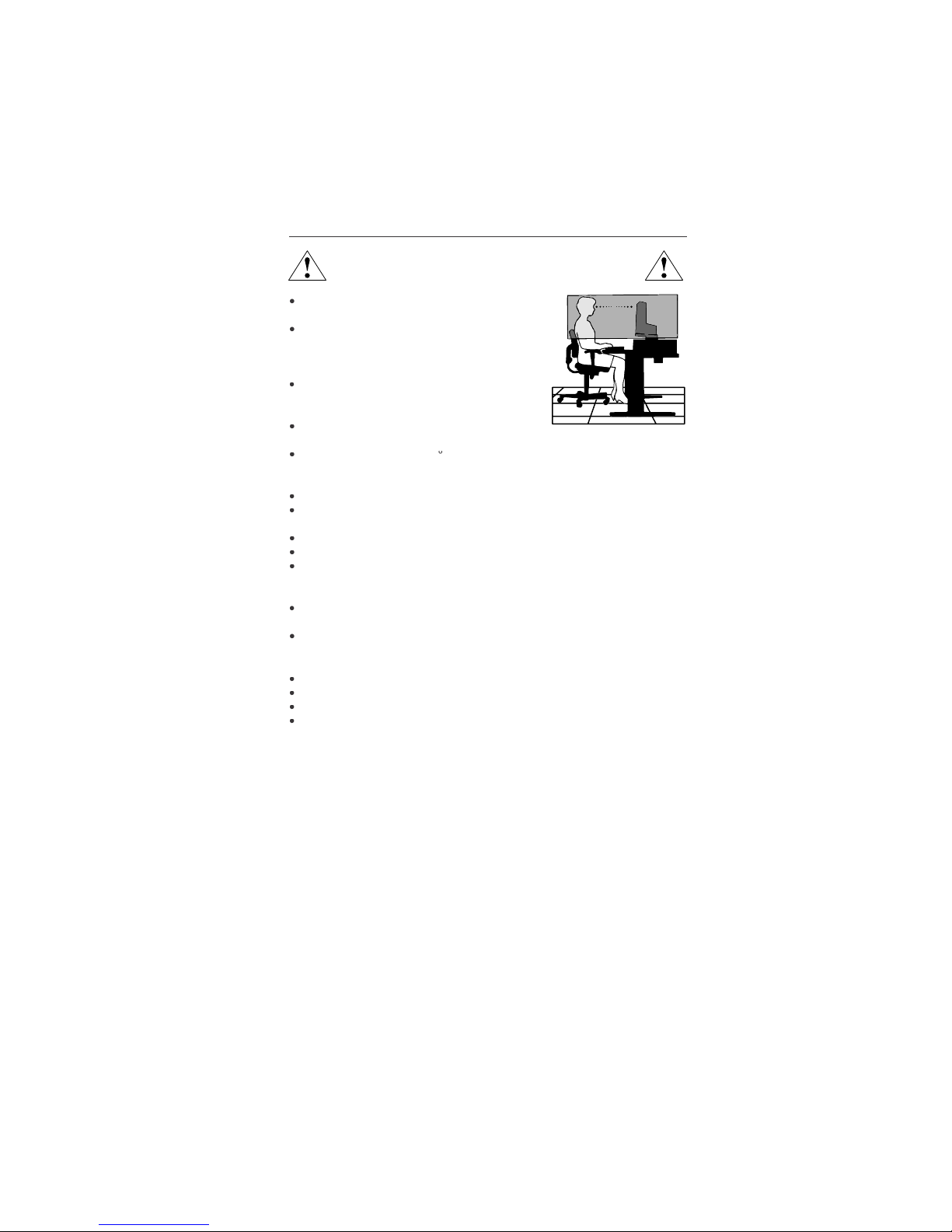
For optimum performance, allow 20 minutes fo
r
w
arm-up
.
Adjust the monitor height so that the top of the
screen is at or s
lightly bel
ow eye level. Your eye
s
should look slightly downward when viewing t
he
middle of the screen
.
Position your monitor no closer than 16 inches
and no
f
urther away than 28 inches from your
eyes. T
h
e optimal distance is 20 inches
.
Rest your eyes periodically by focusing on a
n
object at least 20 feet away. Blink often.
Position the monitor at a 90
angle to windows and other light sources t
o
minimize glare and reflections. Adjust the monitor tilt so that ceiling lights d
o
not reflect on your screen.
If reflected light makes it hard for you to see your screen, use an antiglare filter.
Clean the LCD monitor surface with a lint-free, nonabrasive cloth. Avoid using
any c
l
eaning solution or glass cleaner
!
Adjust the monitor’s brightness and contrast controls to enhance readability
.
Use a document holder placed close to the screen.
Position whatever you are looking at most of the time (the screen o
r
reference material) directly in front of you to minimize turning your hea
d
while you are typing
.
Avoid displaying fixed patterns on the monitor for long periods of time to avoid
image persistence (a
f
terimage effects).
Get regular eye checkups
.
Ergonomic
s
To realize the maximum ergonomics benefits, we recommend the following
:
Use the preset Size and Position controls with standard signa
ls
Use the preset Color Settin
g
Use non-interlaced signals with a vertical refresh rate between 60-75H
z
Do not use primary color blue on a dark background, as it is difficult to see an
d
may produce eye fatigue to insufficient contras
t
For more detailed information on setting up a healthy work environment, write th
e
American National Standard for Human Factors Engineering of Visual Display Termina
l
Workstations – ANSI-HFS Standard No. 100-1988 – The Human Factors Society, Inc
.
P.O. Box 1369, Santa Monica, California 90406
.
1-14
1
2
ifi
cation
s
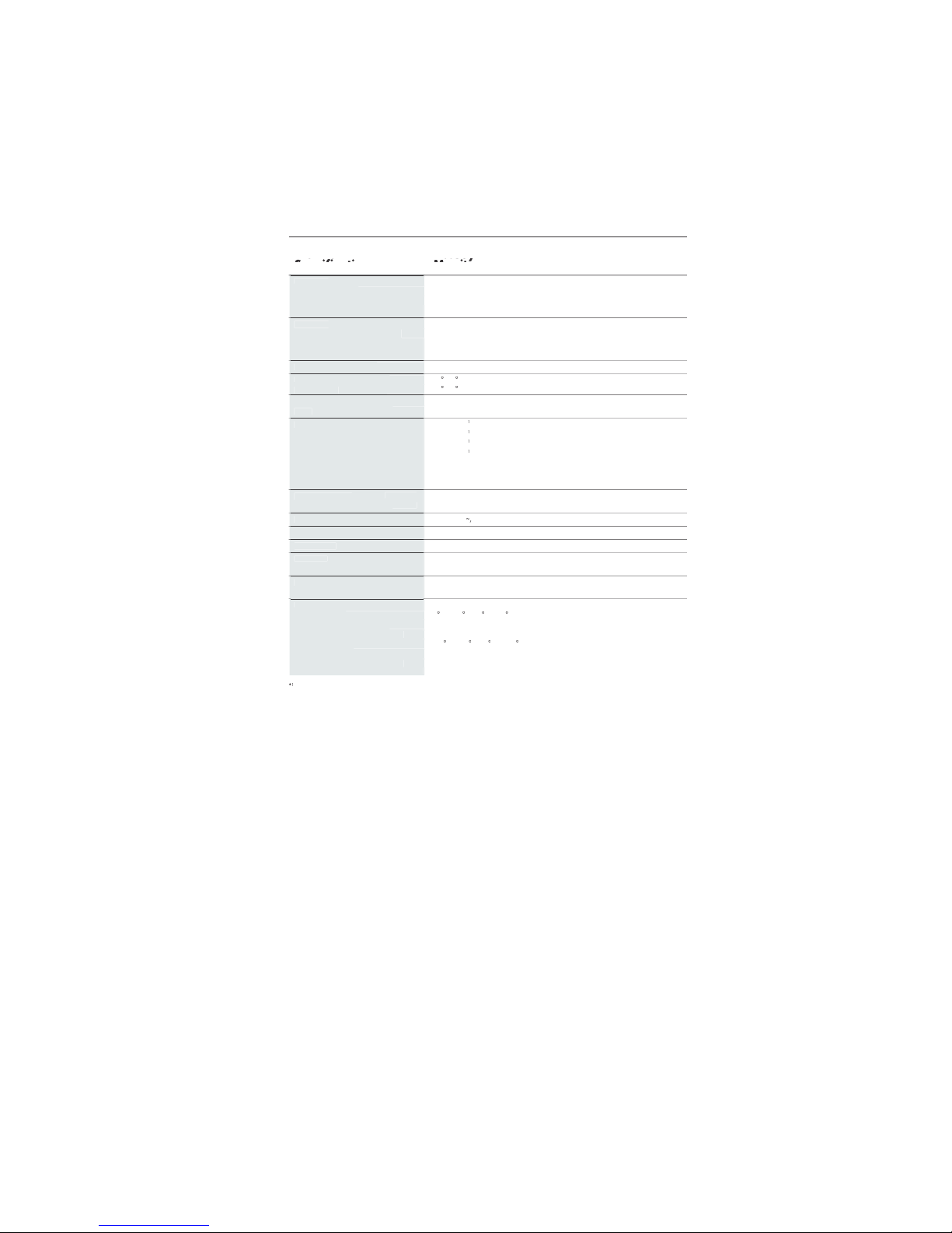
Monitor AccuSync LCD51VM Notes
pec
ificati
ons
Monitor
LCD Modu
le
15.0 inch Active matrix; thin film transistor (TFT
)
Diagonal:
15.0 inc
hl
iquid crystal display (LCD); 0.297 mm do
t
Viewable Image Size:
1024 x 768 pitch; 250c
d/m
Native Resolution (Pixel Count):
2
white luminence
;
450:1 contrast ratio, typica
l
Input Signa
l
ANALOG 0.7 Vp-p/75 Ohm
s
Video:
Separate sync TTL Level (Positive/Negative
)
Sync:
Horizontal sync Positive/Negativ
e
Vertical sync Positive/Negativ
e
Display Color
s
16,777,216 Depending on display card use
d.
Analog input:
Maximu
m
6
0Lef
t/right:/60 (CR>10
)
Viewing Angle
s
4
0Up/
Down:/60 (CR>10
)
nchronizatio
n
31.5 kHz to 60 kHz Automatica
lly
Horizontal:
R
ang
e
56 Hz to 75 Hz Automatica
lly
Vertical:
Resolutions Supported 720 x 400* :VGA tex
t
S
ome systems may not suppor
t
640 x 480* at 60 Hz to 75 H
z
all modes liste
d.
x
600*
at 56 Hz to 75 H
z
832 x 624* at 75
Hz
1024 x 768 at 60 Hz to 75 H
z
NEC-Mitsubishi Electronics Display cite
s
recommended resolution at 75 Hz fo
r
optimal display performance
.
A
ctive Display Are
a
Horizontal :304.1 mm/12.0 inche
s
Vertical :228.1 mm/9.0 inche
s
Power Supp
ly
1
0
0
-240
V
50/60 H
z
Speaker Practical Audio Outpu
t
1 + 1 Watt
s
Current Ratin
g
0.45 - 0.25
A
Dimension
s
347.4 mm (W) x 341.9 mm (H) x 183.5 mm (D
)
13.7 inches (W) x 13.5 inches (H) x 7.2 inches (D
)
Weig
ht
3.0
kg
6.6
lbs
Environmental Consideration
s
5
O
perating Temperature:C to 35C/41F to
95
30% to 80
%
Humidity:
0
to 12,
000
Fee
t
Feet:
-1
0
S
torage Temperature:C to 60C/14F to 1
40
10% to 85
%
Humidity:
0 to 40,000 Fee
t
Feet:
Interpolated Resolutions: When resolutions are shown that are lower than the pixel count of the LCD module, text may appear d
i
ff
erent. This i
s
normal and necessary for all current flat panel technologies when displaying nonnative resolutions full screen. In flat panel technologies, eac
h
dot on the screen is actually one pixel, so to expand resolutions to full screen, an interpolation of the resolution must be d
o
NOTE: Technical specifications are subject to change without notice
.
1-15
1
3
ifi
cations
–continue
d
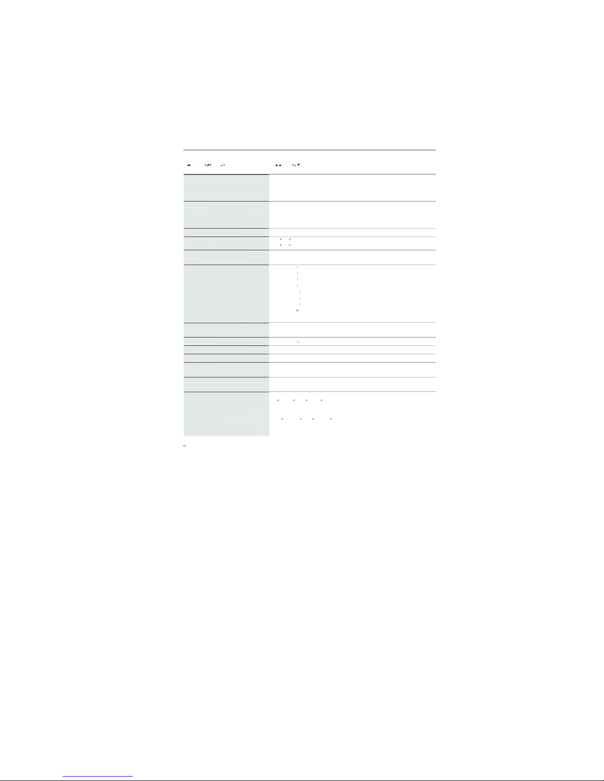
Monitor AccuSync LCD71VM Notes
pec
ificati
ons
Monitor
LCD Modu
le
17.0 inch Active matrix; thin film transistor (TFT
)
Diagonal:
17.0 inc
hl
iquid crystal display (LCD); 0.264 mm do
t
Viewable Image Size:
1280 x 1024 pitch; 250c
d/m
Native Resolution (Pixel Count):
2
white luminence
;
450:1 contrast ratio, typica
l
Input Signa
l
ANALOG 0.7 Vp-p/75 Ohm
s
Video:
Separate sync TTL Level (Positive/Negative
)
Sync:
Horizontal sync Positive/Negativ
e
Vertical sync Positive/Negativ
e
Display Color
s
16,194,277 Depending on display card use
d.
Analog input:
Maximu
m
7
0Lef
t/right:/70 (CR>10
)
Viewing Angle
s
6
0Up/
Down:/60 (CR>10
)
nchronizatio
n
31.5 kHz to 81.1 kHz Automatica
lly
Horizontal:
R
ang
e
56 Hz to 75 Hz Automatica
lly
Vertical:
Resolutions Supported 720 x 400* : VGA tex
t
S
ome systems may not suppor
t
640 x 480* at 60 Hz to 75 H
z
all modes liste
d.
x
600*
at 56 Hz to 75 H
z
832 x 624* at 75
Hz
1024 x 768* at 60 Hz to 75 H
z
1152 x 864* at 70 Hz to 75 H
z
1152 x 870* at 75
Hz
NEC-Mitsubishi Electronics Display cite
s
1
280
x
960
at 60 Hz to 75 H
z
recommended resolution at 60 Hz fo
r
1280 x 1024 at 60 Hz to 75 Hz................optimal display performance
.
A
ctive Display Are
a
Horizontal :338 mm/13.3 inche
s
Vertical :270.3 mm/10.6 inche
s
Power Suppl
y
1
0
0
-240
V
50/60 H
z
Speaker Practical Audio Outpu
t
1 + 1 Watt
s
Current Ratin
g
0.75 - 0.4
A
Dimension
s
379 mm (W) x 383 mm (H) x 193 mm (D
)
14.9 inches (W) x 15.1 inches (H) x 7.6 inches (D
)
Weigh
t
4.
kg
10.2
lbs
Environmental Consideration
s
5
O
perating Temperature:C to 35C/41F to
95
30% to 80
%
Humidity:
0
to 12,
000
Fee
t
Feet:
-1
0
S
torage Temperature:C to +60C/14F to 1
40
10% to 85
%
Humidity:
0 to 40,000 Fee
t
Feet:
Interpolated Resolutions: When resolutions are shown that are lower than the pixel count of the LCD module, text may appear d
i
ff
erent. This i
s
normal and necessary for all current flat panel technologies when displaying non-native resolutions full screen. In flat panel technologies, eac
h
dot on the screen is actually one pixel, so to expand resolutions to full screen, an interpolation of the resolution must be d
o
NOTE: Technical specifications are subject to change without notice
.

1-16
1
4
eature
s
Reduced Footprint: Provides the ideal solution for environments requiring superior image
quality but with size and weight limitations. The monitor’s small
f
ootprint and low weigh
t
allow it to be moved or transported easily from one location to another
.
AccuColo
r
®
Control Systems
: Allows you to adjust the colors on your screen and customiz
e
the color accuracy of your monitor to a variety of standards
.
OSM
®
(On-Screen Manager) Controls: Allow you to quickly and easily adjust all element
s
of your screen image via simple to use on-screen menus
.
No-touch Auto Adjust: No-touch Auto Adjust automatically adjusts the monitor to optima
l
settings upon initial setup
.
ErgoDesig
n
®
Features: Enhance human ergonomics to improve the working environment
,
protect the health of the user and save money. Examples include
OSM controls for quic
k
and easy image adjustments, tilt base for preferred angle of vision, small footprint an
d
compliance with MPRII and TCO guidelines for lower emission
s
Plug and Play
:
The Microsoft
®
solution with the Window
s
®
95/98/Me/2000/XP operat
-
ng system facilitates setup and installation by allowing
the monitor to send its capabilitie
s
(such as screen size and resolutions supported) directly to your computer, automatica
lly
optimizing display performance
.
IP
M
®
(Intelligent Power Manager) System:
Provides innovative power-saving methods tha
t
allow the monitor to shift to a lower power consumption level when on but not in use
,
saving two-thirds of your monitor energy costs, reducing emissions and lowering the ai
r
conditioning costs of the workplace
.
Multiple Frequency Technology: Automatically adjusts monitor to the display card’
s
scanning frequency, thus displaying the resolution required
.
FullSca
n
®
Capability: Allows you to use the entire screen area in most resolutions,
signi
f
icantly expanding image size
.
VESA Standard Mounting Interface: Allows users to connect their AccuSync monitor t
o
any VESA standard third party mounting arm or bracket. Allows for the monitor to b
e
mounted on a wall or an arm using any third party compliant device
.
OSM Display Screen Copyright 2003
by
NEC-Mitsubishi Electronics Display of America, Inc
.

1-17
No pictur
e
The signal cable should be completely connected to the display card/computer
.
The display card should be completely seated in its slot
.
Front Power Switch and computer power switch should be in the ON position.
Check to make sure that a supported mode has been selected on the display card or syste
m
eing used. (Please consult display card or system manual to change graphics mode.
)
Check the monitor and your display card with respect to compatibility and recom
-
mended settings
.
Check the signal cable connector for bent or pushed-in pins
.
Power Button does not respon
d
• Unplug the power cord of the monitor from the AC outlet to turn off and reset the monitor
.
Image Persistenc
e
Image persistence is when a residual or “ghost” image of a previous image remains visibl
e
on the screen. Unlike CRT monitors, LCD monitors’ image persistence is not permanent, bu
t
constant images being displayed for a long period of time should be avoided
.
To
alleviate image persistence, turn off the monitor for as long as the previous image wa
s
displayed. For example, if an image was on the monitor for one hour and a residua
l
image remains, the monitor should be turned off for one hour to erase the image
.
TE: As with all personal display devices, NEC-Mitsubishi Electronics Displa
y
recommends using a moving screen saver at regular intervals whenever the screen i
s
idle or turning off the monitor when not in use
.
Image is unstable, unfocused or swimming is apparen
t
Signal cable should be completely attached to the computer
.
Use the OSM Image Adjust controls to focus and adjust display by increasing o
r
ecreasing the FINE control. When the display mode is changed, the OSM Imag
e
Adjust settings may need to be readjuste
d.
Check the monitor and your display card with respect to compatibilit
y
and recommended signal timings
.
If your text is garbled, change the video mode to non-interlace and use 60Hz refresh rate
.
LED on monitor is not li
t
(no green or amber color can be seen
)
Power Switch should be in the ON position and power cord should be connecte
d.
Display image is not sized proper
ly
Use the OSM Image Adjust controls to increase or decrease the H.SIZE
.
Check to make sure that a supported mode has been selected on the display card or syste
m
eing used. (Please consult display card or system manual to change graphics mode.
)
No Vide
o
If no video is present on the screen, turn the Power button off and on again
.
Make certain the computer is not in a power-saving mode (touch the keyboard or mouse)
.
No Soun
d
Check to see if speaker cable is properly connected
.
Check to see if mute is activated
.
Check to see if volume in OSM is set at minimum
.

1-18
1
6
Refer
e
NEC-Mitsubishi Monitor Customer Service & Support
Customer Service and Technical Support:800) 632-466
2
Fax:(800) 695-304
4
Parts and Accessories/Macintos
h
Cable Adapter: (888) NEC-MITS [888-632-6487]
Customer Service Po
l
icies & Processes:http://www.necmitsubishi.com
/
css/ServicePolicies/ServicePolicies.ht
m
Online Technical Suppor
t
Knowledge Base:
h
ttp://www.necmitsubishi.com
/
css/knowledgebase.c
fm
Customer Service & Technica
l
Support Email:
h
ttp://www.necmitsubishi.com
/
css/techform.ht
m
Sales and Product Informatio
n
Sales Information Line: (888) NEC-MITS [888-632-6487
]
Canadian Customers: (866) 771-0266, Ext#: 403
7
Government Sales: (800) 284-632
0
Government Sales email: gov@necmitsubishi.co
m
Rebate Status Informatio
n
NEC Rebate Status: www.rebatesHQ.com or 866-765-569
6
Mitsubishi Rebate Status: www.rebatesHQ.com or 877-405-469
2
Electronic Channe
ls
World Wide Web:
h
ttp://www.necmitsubishi.co
m
Product Registration:
h
ttp://www.necmitsubishi.com
/
productregistratio
n
European Operations: http://www.nec-mitsubishi.com
Window
s
®
95/98/Me/2000/XP INF File:ttp://www.necmitsubishi.com and selec
t
“Drivers and Downloads”

1-19
Limited Warrant
y
NEC-Mitsubishi Electronics Display of America, Inc. (hereinafter “NMD-A”) warrants thi
s
Product to be free from defects in material and workmanship and, subject to the conditions se
t
orth below, agrees to repair or replace (at NMD-A’s sole option) any part of the enclosed uni
t
w
hich proves defective for a period of three (3) years from the date of first consumer purchase
.
Spare parts are warranted for ninety (90) days. Replacement parts or unit may be new o
r
refurbished and will meet specifications of the original parts or unit
.
This warranty gives you specific legal rights and you may also have other rights, which var
y
rom state to state. This warranty is limited to the original purchaser of the Product and is no
t
transferable. This warranty covers only NMD-A-supplied components. Service required as
a
result of third party components is not covered under this warranty. In order to be covere
d
under this warranty, the Product must have been purchased in the U.S.A. or Canada by t
he
original purchaser. This warranty only covers Product distribution in the U.S.A. or Canada
by
NMD-A No warranty service is provided outside of the U.S.A. or Canada. Proof of Purchas
e
w
ill be required by NMD-A to substantiate date of purchase. Such proof of purchase must b
e
an original bill of sale or receipt containing name and address of seller, purchaser, and th
e
serial number of the product
.
It shall be your obligation and expense to have the Product shipped, freight prepaid, o
r
delivered to the authorized reseller from whom it was purchased or other facility authorize
d
y NMD-A to render the services provided hereunder in either the original package or
a
similar package affording an equal degree of protection. All Products returned to NMD-A fo
r
service MUST have prior approval, which may be obtained by calling 1-800-632-4662. Th
e
Product shall not have been previously altered, repaired, or serviced by anyone other than
a
service facility authorized by NMD-A to render such service, the serial number of the produc
t
shall not have been altered or removed. In order to be covered by this warranty the Produc
t
shall not have been subjected to displaying of fixed images for long periods of time resultin
g
in image persistence (afterimage effects), accident, misuse or abuse or operated contrary t
o
the instructions contained in the User’s Manual. Any such conditions will void this warranty
.
MD-A SHALL NOT BE LIABLE FOR DIRECT, INDIRECT, INCIDENTAL, CONSEQUENTIAL
,
OR OTHER TYPES OF DAMAGES RESULTING FROM THE USE OF ANY NMD-A PRODUC
T
OTHER THAN THE LIABILITY STATED ABOVE. THESE WARRANTIES ARE IN LIEU OF AL
L
OTHER WARRANTIES EXPRESS OR IMPLIED, INCLUDING, BUT NOT LIMITED TO, TH
E
IMPLIED WARRANTIES OF MERCHANTABILITY OR FITNESS FOR A PARTICULAR PURPOSE
.
SOME STATES DO NOT ALLOW THE EXCLUSION OF IMPLIED WARRANTIES OR TH
E
LIMITATION OR EXCLUSION OF LIABILITY FOR INCIDENTAL OR CONSEQUENTIAL DAM
-
AGES SO THE ABOVE EXCLUSIONS OR LIMITATIONS MAY NOT APPLY TO YOU
.
This Product is warranted in accordance with the terms of this limited warranty. Consumer
s
are cautioned that Product performance is affected by system configuration, software, th
e
application, customer data, and operator control of the system, among other factors. Whil
e
NMD-A Products are considered to be compatible with many systems, specific functiona
l
implementation by the customers of the Product may vary. Therefore, suitability of a Produc
t
or a specific purpose or application must be determined by consumer and is not warrante
d
by NMD-A
.
For the name of your nearest authorized NEC-Mitsubishi Electronics Display service facility
,
contact NEC-Mitsubishi Electronics Display of America at 1-800-632-4662
.

1-20
1
8
TCO’9
9
Congratulations! You have just purchased a TCO’99 approved an
d
abelled product! Your choice has provided you with a product develope
d
or professional use. Your purchase has also contributed to reducing th
e
burden on the environment and also to the further development o
f
environmentally adapted electronics products
.
Why do we have environmentally labelled computers
?
In many countries, environmental labelling has become an established method for encourag
-
ing the adaptation of goods and services to the environment. The main problem, as far a
s
computers and other electronics equipment are concerned, is that environmentally harmfu
l
substances are used both in the products and during the manufacturing. Since it has not bee
n
possible for the majority of electronics equipment to be recycled in a satisfactory way, mos
t
of these potentially damaging substances sooner or later enter Nature
.
There are also other characteristics of a computer, such as energy consumption levels, that ar
e
important from the viewpoints of both the work (Internal) and natural (external) environments
.
Since all methods of conventional electricity generation have a negative effect on th
e
environment (acidic and climate-influencing emissions, radioactive waste, etc.), it is vital t
o
conserve energy. Electronics equipment in offices consume an enormous amount of energ
y
since they are often left running continuously
.
What does labelling involve
?
This product meets the requirements for the TCO’99 scheme which provides for international an
d
environmental labelling of personal computers. The labelling scheme was developed as a join
t
effort by the TCO (The Swedish Confederation of Professional Employees), Svensk
a
Naturskyddsforeningen (The Swedish Society for Nature Conservation) and Statens Energimyndighe
t
(The Swedish National Energy Administration)
.
The requirements cover a wide range of issues: environment, ergonomics, usability, emission o
f
electrical and magnetic fields, energy consumption and electrical and fire safety
.
The environmental demands concern restrictions on the presence and use of heavy metals
,
brominated and chlorinated flame retardants, CFCs (freons) and chlorinated solvents, among othe
r
things. The product must be prepared for recycling and the manufacturer is obliged to have a
n
environmental plan which must be adhered to in each country where the company implements it
s
operational policy. The energy requirements include a demand that the computer and/or display
,
after a certain period of inactivity, shall reduce its power consumption to a lower level in one o
r
more stages. The length of time to reactivate the computer shall be reasonable for the user
.
Labelled products must meet strict environmental demands, for example, in respect of the reductio
n
of electric and magnetic fields, physical and visual ergonomics and good usability
.
Environmental Requirement
s
Flame retardant
s
Flame retardants are present in printed circuit boards, cables, wires, casings and housings. In turn
,
they delay the spread of fire. Up to thirty percent of the plastic in a computer casing can consist o
f
lame retardant substances. Most flame retardants contain bromine or chloride and these ar
e
related to another group of environmental toxins, PCBs, which are suspected to give rise to sever
e
health effects, including reproductive damage in fisheating birds and mammals, due to the bio
-

1-21
1
9
TCO’99
–continue
d
accumulative* processes. Flame retardants have been found in human blood and researchers fea
r
that disturbances in foetus development may occur
.
TCO’99 demand requires that plastic components weighing more than 25 grams must not contai
n
lame retardants with organically bound chlorine and bromine. Flame retardants are allowed i
n
the printed circuit boards since no substitutes are available
.
Lead*
*
Lead can be found in picture tubes, display screens, solders and capacitors. Lead damages th
e
nervous system and in higher doses, causes lead poisoning
.
TCO’99 requirement permits the inclusion of lead since no replacement has yet been developed
.
Cadmium*
*
Cadmium is present in rechargeable batteries and in the color generating layers of certain compute
r
isplays. Cadmium damages the nervous system and is toxic in high doses
.
TCO’99 requirement states that batteries, the color generating layers of display screens and th
e
electrical or electronics components must not contain any cadmium
.
M
ercury**
Mercury is sometimes found in batteries, relays and switches, Mercury damages the nervous syste
m
and is toxic in high doses
.
TCO’99 requirement states that batteries may not contain any Mercury. It also demands that n
o
mercury is present in any of the electrical or electronics components associated with the display unit
.
CFCs
(freons)
CFCs (freons) are sometimes used for washing printed circuit boards. CFCs break down ozone an
d
thereby damage the ozone layer in the stratosphere, causing increased reception on Earth o
f
ultraviolet light with consequent increased risks of skin cancer (malignant melanoma)
.
The relevant TCO’99 requirement; Neither CFCs nor HCFCs may be used during the manufacturin
g
and assembly of the product or its packaging
.
*Bio-accumulative is defined as substances which accumulate within living organisms
.
**Lead, Cadmium and Mercury are heavy metals which are Bio-accumulative
.
To obtain complete information on the environmental criteria document, order from:
TCO Deve
l
opment Unit
SE-114 94 Stoc
khol
m
SWEDE
N
FAX Number: +46 8 782 92 07
-mail (Internet): development@tco.se
You may also obtain current in
f
ormation on TCO’99 approved and labelled products by
visiting t
h
eir website at: http://www.tcodevelopment.com
/
1-22
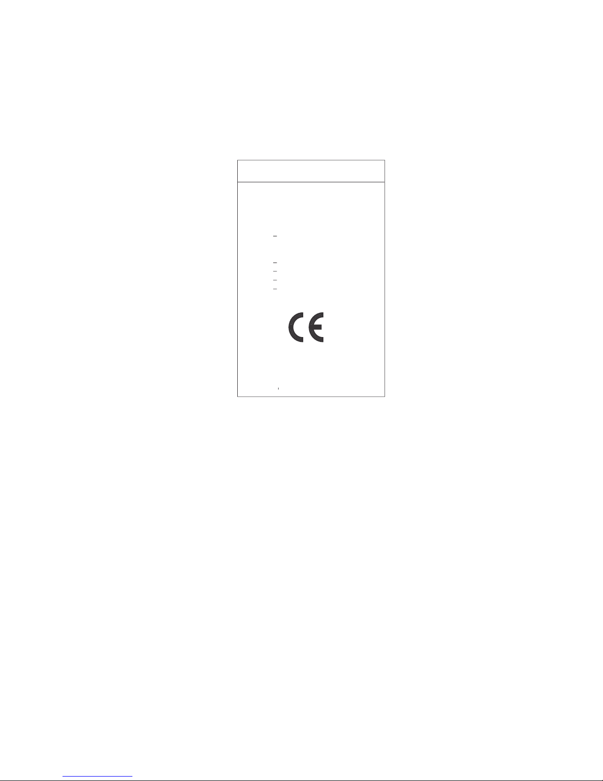
Declaration of the Manufacture
r
We
hereby certify that the color monito
r
AccuSync™ LCD51VM (L152R5) an
d
AccuSync LCD71VM (L172R6
)
in compliance wit
h
Council Directive 73/23/EEC
:
EN 6095
0
Council Directive 89/336/EEC
:
EN 5502
2
EN 61000-3-
2
EN 61000-3-
3
EN 5502
4
and marked wit
h
NEC-Mitsubishi Electric Visua
l
ystems Corporatio
n
4-13-23, Shibaura
,
Minato-K
u
T
okyo 108-0023, Japan
1-23
Part No. 1550168
1
Printed in Chin
a
PROPRIETARY NOTICE AND LIABILITY DISCLAIME
R
The information disclosed in this document, including all designs and related materials, is the valuable property of NECMitsubishi Electronics Display o
f
America and/or its licensors, as appropriate, reserve all patent, copyright and other
proprietary rights to this document, including all design, manu
f
acturing, reproduction, use and sales rights thereto, except
to t
h
e extent said rights are expressly granted to others.
The NEC-Mitsubishi Electronics Display o
f
America product(s) discussed in this document are warranted in accordance
with the terms o
f
the Limited Warranty Statement accompanying each product. However, actual performance of each
such product is dependent upon
f
actors such as system configuration, customer data and operator control. Since
implementation by customers o
f
each product may vary, the suitability of specific product configurations and applications
must be determined by the customer and is not warranted by NEC-Mitsubishi Electronics Display o
f
America
.
To allow for design and specification improvements, the information in this document is subject to change at any tim
e
without notice. Reproduction of this document or portions thereof without prior approval of NEC-Mitsubishi Electronics
Display o
f
America is prohibited.
DECLARATION OF CONFORMIT
Y
This device complies with Part 15 of FCC Rules. Operation is subject to the following two conditions. (1) This device may
not cause harm
f
ul interference, and (2) this device must accept any interference received, including interference that ma
y
cause undesired operation.
U.S. Responsible Party: NEC-Mitsubishi Electronics Display o
f
America, Inc.
A
dd
ress: 1250 North Arlington Heights Road, Suite 500
Itasca, I
ll
inois 60143-124
8
Tel. No.: (630) 467-300
0
Type of Product: Display Monito
r
Equipment Classification: Class B Peripheral
Mo
del:
AccuSync LCD51VM (L152R5) / LCD71VM (L172R6
)
We hereby declare that the equipment specified above
conforms to the technical standards as specified in the FCC Rules
.
Windows is a registered trademark of Microsoft Corporation. NEC is a registered trademark of NEC Corporation
.
E
S
T
AR
s
a
U.S. registered trademark. All other brands and product names are trademarks or registered trademarks of their respective owner
s
A
s an
ERG
Y
S
T
AR
®
Partner, NEC-Mitsubishi Electronics Display of America has determined that this product meets the
ERG
Y
S
T
AR
guidelines for energy efficiency. The
ERG
Y
S
T
AR
emblem does not represent EPA endorsement of any product or service.
NEC LCD Series

1-24
2. B Version
AccuSync LCD51VM
AccuSync LCD71VM
User’s Manual

1-25
English
English-1
Declaration
Declaration of the Manufacturer
TO PREVENT FIRE OR SHOCK HAZARDS, DO NOT EXPOSE THIS UNIT TO RAIN OR MOISTURE. ALSO, DO NOT
USE THIS UNIT’S POLARIZED PLUG WITH AN EXTENSION CORD RECEPTACLE OR OTHER OUTLETS UNLESS
THE PRONGS CAN BE FULLY INSERTED.
REFRAIN FROM OPENING THE CABINET AS THERE ARE HIGH VOLTAGE COMPONENTS INSIDE. REFER
SERVICING TO QUALIFIED SERVICE PERSONNEL.
WARNING
CAUTION
CAUTION: TO REDUCE THE RISK OF ELECTRIC SHOCK, DO NOT REMOVE COVER (OR BACK). NO USER
SERVICEABLE PARTS INSIDE. REFER SERVICING TO QUALIFIED SERVICE PERSONNEL.
This symbol warns user that uninsulated voltage within the unit may have sufficient magnitude to cause
electric shock. Therefore, it is dangerous to make any kind of contact with any part inside this unit.
This symbol alerts the user that important literature concerning the operation and maintenance of this unit
has been included. Therefore, it should be read carefully in order to avoid any problems.
RISK OF ELECTRIC SHOCK • DO NOT OPEN
As an E
NERGY STAR
Partner, NEC-Mitsubishi Electric Visual Systems Corp. has determined that this product meets the E
NERGY
S
TAR
guidelines for energy efficiency. E
NERGY STAR
is a U.S. registered mark.
ErgoDesign is a registred trademark of NEC-Mitsubishi Electric Visual Systems Corporation in Austria, Benelux, Denmark,
France, Germany, Italy, Norway, Spain, Sweden, U.K..
IBM PC/XT/AT, PS/2, MCGA, VGA, 8514/A and XGA are registered trademarks of International Business Machines
Corporation.
Apple and Macintosh are registered trademarks of Apple Computer Inc.
Microsoft and Windows are registered trademarks of the Microsoft Corporation.
NEC is a registered trademark of NEC Corporation.
All other trademarks or registered trademarks are property of their respective owners.
We hereby certify that the colour monitor
AccuSync LCD51VM/AccuSync LCD71VM
are in compliance with
Council Directive 73/23/EEC:
– EN 60950
Council Directive 89/336/EEC:
– EN 55022
– EN 61000-3-2
– EN 61000-3-3
– EN 55024
and marked with
NEC-Mitsubishi Electric Visual
Systems, Corp.
MS Shibaura Bldg., 13-23,
Shibaura 4-chome,
Minato-Ku, Tokyo 108-0023, Japan
Caution:
When operating the AccuSync LCD51VM/AccuSync LCD71VM with a 220-240V AC power source in Europe, use the power
cord provided with the monitor.
In the UK, a BS approved power cord with a moulded plug has a Black (five Amps) fuse installed for use with this equipment.
If a power cord is not supplied with this equipment please contact your supplier.
For all other cases, use a power cord that matches the AC voltage of the power outlet and has been approved by and
complies with the safety standard of your particular country.
1-26
English-2
For the Customer to use in U.S.A. or Canada
Canadian Department of Communications Compliance Statement
DOC: This Class B digital apparatus meets all requirements of the Canadian Interference-Causing Equipment Regulations.
Cet appareil numérique de la classe B respecte toutes les exigences du Règlement sur le matériel brouiller du Canada.
C-UL: Bears the C-UL Mark and is in compliance with Canadian Safety Regulations according to CSA C22.2 No. 60950.
Ce produit porte la marque ‘C-UL’ et se conforme aux règlements de sûrele Canadiens selon CAN/CSA C22.2 No. 60950.
FCC Information
1. Use the attached specified cables with the AccuSync LCD51VM/AccuSync LCD71VM colour monitor so as not to
interfere with radio and television reception.
(1) The power supply cord you use must have been approved by and comply with the safety standards of U.S.A.,
and meet the following condition.
Power supply cord Non shield type, 3-conductor
Length 2.0 m
Plug shape
U.S.A
(2) Shielded video signal cable. Use of other cables and adapters may cause interference with radio and television
reception.
2. This equipment has been tested and found to comply with the limits for a Class B digital device, pursuant to part 15 of
the FCC Rules. These limits are designed to provide reasonable protection against harmful interference in a residential
installation. This equipment generates, uses, and can radiate radio frequency energy, and, if not installed and used in
accordance with the instructions, may cause harmful interference to radio communications. However, there is no
guarantee that interference will not occur in a particular installation. If this equipment does cause harmful interference
to radio or television reception, which can be determined by turning the equipment off and on, the user is encouraged
to try to correct the interference by one or more of the following measures:
• Reorient or relocate the receiving antenna.
• Increase the separation between the equipment and receiver.
• Connect the equipment into an outlet on a circuit different from that to which the receiver is connected.
• Consult your dealer or an experienced radio/TV technician for help.
If necessary, the user should contact the dealer or an experienced radio/television technician for additional
suggestions. The user may find the following booklet, prepared by the Federal Communications Commission, helpful:
“How to Identify and Resolve Radio-TV Interference Problems.” This booklet is available from the U.S. Government
Printing Office, Washington, D.C., 20402, Stock No. 004-000-00345-4.
Declaration of Conformity
This device complies with Part 15 of FCC Rules. Operation is subject to the following two conditions. (1) This device may not
cause harmful interference, and (2) this device must accept any interference received, including interference that may cause
undesired operation.
U.S. Responsible Party: NEC-Mitsubishi Electronics Display of America, Inc.
Address: 1250 N. Arlington Heights Road
Itasca, Illinois 60143-1248
Tel. No.: (630) 467-3000
Type of Product: Display Monitor
Equipment Classification: Class B Peripheral
Model: AccuSync LCD51VM/AccuSync LCD71VM
We hereby declare that the equipment specified above conforms
to the technical standards as specified in the FCC Rules.
1-27
English
English-3
Contents
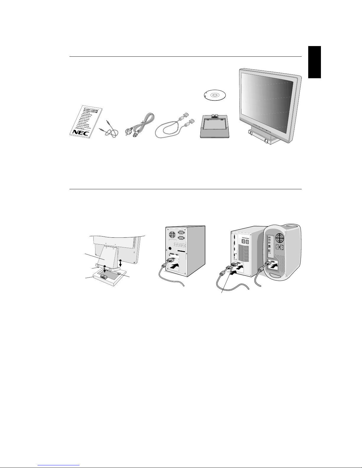
Your new NEC AccuSync LCD monitor box* should contain the following:
• AccuSync LCD monitor with tilt base
• Audio Cable
• Power Cord
• Video Signal Cable
• User’s Manual
• CD-ROM
*
Remember to save your original box and packing material to transport or ship the monitor.
Quick Start
To attach the Base to the LCD Stand:
1. Insert the front of the LCD stand into the holes in the front of the Base (Figure S.1).
2. Next, position the locking tabs on the back side of the LCD stand with the holes on the Base. Lower the Stand in place until
locking tabs are secure (Figure S.1).
Figure A.1
To attach the AccuSync LCD monitor to your system, follow these instructions:
1. Turn off the power to your computer.
2. For the PC with Analog output: Connect the 15-pin mini D-SUB signal cable to the connector of the display card in your
system (Figure A.1). Tighten all screws.
For the Mac: Connect the MultiSync Macintosh cable adapter (not included) to the computer. Attach the 15-pin
mini D-SUB signal cable to the MultiSync Macintosh cable adapter (Figure A.2). Tighten all screws.
NOTE: Some Macintosh systems do not require a Macintosh cable adapter.
User’s Manual Audio Cable Power Cord
Video Signal Cable
Base Stand AccuSync LCD monitor
(base stand not connected)
Figure S.1
1
2
Front Base
Holes
Base
Locking Tabs
Stand
Figure A.2
Macintosh Cable
Adapter (not included)
CD-ROM
 Loading...